EP4513074A1 - Vehicle pipeline mounting head, pipeline structure and vehicle - Google Patents
Vehicle pipeline mounting head, pipeline structure and vehicle Download PDFInfo
- Publication number
- EP4513074A1 EP4513074A1 EP23869917.7A EP23869917A EP4513074A1 EP 4513074 A1 EP4513074 A1 EP 4513074A1 EP 23869917 A EP23869917 A EP 23869917A EP 4513074 A1 EP4513074 A1 EP 4513074A1
- Authority
- EP
- European Patent Office
- Prior art keywords
- pipeline
- vehicle
- mounting plate
- snap
- subframe
- Prior art date
- Legal status (The legal status is an assumption and is not a legal conclusion. Google has not performed a legal analysis and makes no representation as to the accuracy of the status listed.)
- Pending
Links
Images

Classifications
-
- F—MECHANICAL ENGINEERING; LIGHTING; HEATING; WEAPONS; BLASTING
- F16—ENGINEERING ELEMENTS AND UNITS; GENERAL MEASURES FOR PRODUCING AND MAINTAINING EFFECTIVE FUNCTIONING OF MACHINES OR INSTALLATIONS; THERMAL INSULATION IN GENERAL
- F16L—PIPES; JOINTS OR FITTINGS FOR PIPES; SUPPORTS FOR PIPES, CABLES OR PROTECTIVE TUBING; MEANS FOR THERMAL INSULATION IN GENERAL
- F16L41/00—Branching pipes; Joining pipes to walls
- F16L41/08—Joining pipes to walls or pipes, the joined pipe axis being perpendicular to the plane of a wall or to the axis of another pipe
-
- F—MECHANICAL ENGINEERING; LIGHTING; HEATING; WEAPONS; BLASTING
- F16—ENGINEERING ELEMENTS AND UNITS; GENERAL MEASURES FOR PRODUCING AND MAINTAINING EFFECTIVE FUNCTIONING OF MACHINES OR INSTALLATIONS; THERMAL INSULATION IN GENERAL
- F16L—PIPES; JOINTS OR FITTINGS FOR PIPES; SUPPORTS FOR PIPES, CABLES OR PROTECTIVE TUBING; MEANS FOR THERMAL INSULATION IN GENERAL
- F16L41/00—Branching pipes; Joining pipes to walls
- F16L41/02—Branch units, e.g. made in one piece, welded, riveted
- F16L41/021—T- or cross-pieces
-
- B—PERFORMING OPERATIONS; TRANSPORTING
- B60—VEHICLES IN GENERAL
- B60K—ARRANGEMENT OR MOUNTING OF PROPULSION UNITS OR OF TRANSMISSIONS IN VEHICLES; ARRANGEMENT OR MOUNTING OF PLURAL DIVERSE PRIME-MOVERS IN VEHICLES; AUXILIARY DRIVES FOR VEHICLES; INSTRUMENTATION OR DASHBOARDS FOR VEHICLES; ARRANGEMENTS IN CONNECTION WITH COOLING, AIR INTAKE, GAS EXHAUST OR FUEL SUPPLY OF PROPULSION UNITS IN VEHICLES
- B60K11/00—Arrangement in connection with cooling of propulsion units
- B60K11/02—Arrangement in connection with cooling of propulsion units with liquid cooling
-
- F—MECHANICAL ENGINEERING; LIGHTING; HEATING; WEAPONS; BLASTING
- F16—ENGINEERING ELEMENTS AND UNITS; GENERAL MEASURES FOR PRODUCING AND MAINTAINING EFFECTIVE FUNCTIONING OF MACHINES OR INSTALLATIONS; THERMAL INSULATION IN GENERAL
- F16L—PIPES; JOINTS OR FITTINGS FOR PIPES; SUPPORTS FOR PIPES, CABLES OR PROTECTIVE TUBING; MEANS FOR THERMAL INSULATION IN GENERAL
- F16L37/00—Couplings of the quick-acting type
- F16L37/02—Couplings of the quick-acting type in which the connection is maintained only by friction of the parts being joined
- F16L37/04—Couplings of the quick-acting type in which the connection is maintained only by friction of the parts being joined with an elastic outer part pressing against an inner part by reason of its elasticity
-
- F—MECHANICAL ENGINEERING; LIGHTING; HEATING; WEAPONS; BLASTING
- F16—ENGINEERING ELEMENTS AND UNITS; GENERAL MEASURES FOR PRODUCING AND MAINTAINING EFFECTIVE FUNCTIONING OF MACHINES OR INSTALLATIONS; THERMAL INSULATION IN GENERAL
- F16L—PIPES; JOINTS OR FITTINGS FOR PIPES; SUPPORTS FOR PIPES, CABLES OR PROTECTIVE TUBING; MEANS FOR THERMAL INSULATION IN GENERAL
- F16L41/00—Branching pipes; Joining pipes to walls
- F16L41/02—Branch units, e.g. made in one piece, welded, riveted
- F16L41/03—Branch units, e.g. made in one piece, welded, riveted comprising junction pieces for four or more pipe members
-
- F—MECHANICAL ENGINEERING; LIGHTING; HEATING; WEAPONS; BLASTING
- F16—ENGINEERING ELEMENTS AND UNITS; GENERAL MEASURES FOR PRODUCING AND MAINTAINING EFFECTIVE FUNCTIONING OF MACHINES OR INSTALLATIONS; THERMAL INSULATION IN GENERAL
- F16L—PIPES; JOINTS OR FITTINGS FOR PIPES; SUPPORTS FOR PIPES, CABLES OR PROTECTIVE TUBING; MEANS FOR THERMAL INSULATION IN GENERAL
- F16L5/00—Devices for use where pipes, cables or protective tubing pass through walls or partitions
- F16L5/02—Sealing
- F16L5/14—Sealing for double-walled or multi-channel pipes
-
- F—MECHANICAL ENGINEERING; LIGHTING; HEATING; WEAPONS; BLASTING
- F16—ENGINEERING ELEMENTS AND UNITS; GENERAL MEASURES FOR PRODUCING AND MAINTAINING EFFECTIVE FUNCTIONING OF MACHINES OR INSTALLATIONS; THERMAL INSULATION IN GENERAL
- F16L—PIPES; JOINTS OR FITTINGS FOR PIPES; SUPPORTS FOR PIPES, CABLES OR PROTECTIVE TUBING; MEANS FOR THERMAL INSULATION IN GENERAL
- F16L55/00—Devices or appurtenances for use in, or in connection with, pipes or pipe systems
- F16L55/02—Energy absorbers; Noise absorbers
- F16L55/033—Noise absorbers
- F16L55/0337—Noise absorbers by means of a flexible connection
Definitions
- the present disclosure relates to the field of vehicles, in particular to a pipeline mounting head for a vehicle, a pipeline structure and a vehicle.
- the battery usually generates heat to increase the temperature of a battery pack, which affects the use effect and the service life of the battery pack, so it is necessary to install a cooling system to cool the battery.
- a cooling system is installed in the prior art, a four-way pipeline is generally installed on a vehicle body at first, then a cooling water pipe is assembled, and finally a subframe is installed and locked by screws/nuts. The whole installation process is complicated, and it is difficult to ensure the sealing between the cooling system and the vehicle body after installation.
- the present disclosure aims to provide a pipeline mounting head for a vehicle, a pipeline structure and a vehicle, which has a simple structure and convenient installation and can ensure the sealing between the pipeline structure and the vehicle.
- the present disclosure provides a pipeline mounting head for a vehicle, which comprises a mounting plate, two branch pipelines located on one side of the mounting plate, and a main pipeline located on the other side of the mounting plate and communicated with the branch pipelines; the mounting plate is provided with a snap-fit member; and the snap-fit member and the branch pipelines are located on the same side of the mounting plate.
- the snap-fit member is provided with an elastically deformable snap-fit member, and a gap is provided between the snap-fit member and the mounting plate.
- the mounting plate is provided with a sealing gasket
- the sealing gasket is in the shape of a square
- the middle of the sealing gasket is provided with an opening through which the branch pipelines and the snap-fit member penetrate.
- the present disclosure provides a pipeline structure, which comprises any of the above pipeline mounting heads for the vehicle, and further comprises a cooling water pipe connected with the main pipeline.
- the cooling water pipe comprises a corrugated pipe and a nylon pipe connected with the corrugated pipe, and the corrugated pipe is connected with both ends of the main pipeline.
- the present disclosure provides a vehicle, comprising the above pipeline structure, and further comprising a vehicle body and a subframe assembled on the vehicle body, and after the pipeline structure is assembled on the subframe, the subframe is assembled with the vehicle body.
- a sheet metal member of the vehicle body is provided with a fixing hole, the snap-fit member penetrates through the fixing hole and then is snapped on the sheet metal member, the sealing gasket is located between the mounting plate and the sheet metal member, and the sheet metal member is snapped in the gap.
- the cooling water pipe is provided with a fixing bracket, the cooling water pipe is fixed with the subframe through the fixing bracket, the cooling water pipe comprises a corrugated pipe connected with both ends of the main pipeline, and a buffer space exists between the cooling water pipe and the subframe.
- the subframe is provided with a positioning hole matched with the positioning pin, the positioning pin is fixed in the positioning pin before disconnected, and a gap exists between a pipeline joint and the subframe.
- the mounting plate is provided with the snap-fit member which is deformable, and the pipeline structure is formed after the cooling water pipe is mounted on the pipeline joint for the vehicle.
- the snap-fit member and the vehicle body are snapped for fixation.
- the sheet metal member of the vehicle body compacts a sealing element and then is snapped in the gap between the snap-fit member and the mounting plate to ensure a sealing effect.
- the disconnectable positioning pin is arranged on the main pipeline, which can ensure that the pipeline structure is accurately mounted on the vehicle body and the subframe to reduce the mounting difficulty.
- the present disclosure provides a pipeline mounting head 100 for a vehicle, and the pipeline mounting head 100 for the vehicle is assembled on a vehicle 300 together with a pipeline structure 200.
- the pipeline mounting head 100 for the vehicle includes a mounting plate 11, two branch pipelines 12 located on one side of the mounting plate 11, and a main pipeline 13 located on the other side of the mounting plate 11 and communicated with the branch pipelines 12.
- the pipeline mounting head 100 for the vehicle is mounted to a vehicle body 31, the two branch pipelines 12 are located in the vehicle body 31, and the main pipeline 13 is located outside the vehicle body 31.
- the branch pipelines 12 are cylindrical.
- each branch pipeline 12 is provided with a quick-insert structure or a snap-fit structure.
- the branch pipeline 12 is provided with the quick-insert structure.
- a middle part of the branch pipeline 12 is provided with at least two bulges. An outer diameter of each of the bulges is greater than a whole outer diameter of the branch pipeline 12, and a groove 122 is arranged between the bulges.
- a bulge at the top of the branch pipeline 12 is arranged as a bevel bulge 121.
- the bevel of the bevel bulge 121 is formed by extending a surface of the branch pipeline 12 to the bulge, and the bevel is set to facilitate the quick insertion of the branch pipeline 12 into the vehicle body 31.
- two grooves 122 are formed between the bulges on the branch pipeline 12.
- the branch pipeline 12 can be quickly inserted into the vehicle body 31 by providing the bevel bulge 121 and a plurality of grooves 122 on the branch pipeline 12.
- the branch pipeline 12 is provided with the snap-fit structure to facilitate the coordination between the branch pipeline 12 and the vehicle body 31.
- the main pipeline 13 is communicated with the two branch pipelines 12 in a vertical direction.
- the main pipeline 13 includes a left main pipeline 131 and a right main pipeline 132, and the left main pipeline 131 and the right main pipeline 132 have a same inner diameter.
- a connecting part 133 is arranged between the left main pipeline 131 and the right main pipeline 132.
- An inner diameter of the connecting part 133 is less than the inner diameter of the left main pipeline 131 and right main pipeline 132.
- a mounting part 134 is arranged at an outlet of the left main pipeline 131 and the right main pipeline 132 respectively, and a sealing structure 135 is arranged on the mounting part 134, which can improve the sealing effect between the mounting part 134 and a cooling water pipe 21.
- the mounting plate 11 is provided with an elastically deformable snap-fit member 14, and the snap-fit member 14 and the branch pipelines 12 are located on a same side of the mounting plate 11.
- the snap-fit member 14 is used to snap-fit with the vehicle body 31.
- the snap-fit member 14 is provided with a snap-fit part 141, the snap-fit part 141 can generate elastic deformation under stress, and a gap 142 is arranged between the snap-fit part 141 and the mounting plate 11.
- the snap-fit member 14 includes an elastically deformable snap-fit part and a fixed part which is fixed to the mounting plate.
- the snap-fit part is arranged on the fixed part, and a gap is arranged between a bottom of the snap-fit part and the mounting plate 11.
- a lower part of the main pipeline 13 is provided with a positioning pin 15 which is arranged perpendicular to the mounting plate 11.
- the positioning pin 15 is fixed on the main pipeline 13 by hot melting.
- the positioning pin 15 is subjected to a force of which a direction is different from directions of forces acting on the mounting plate 11 and the main pipeline 13, the positioning pin 15 is disconnected from the main pipeline 13.
- the pipeline structure 200 is applied to the vehicle 300, and the vehicle 300 is provided with the vehicle body 31 and the subframe 32 assembled on the vehicle body 31.
- the positioning pin 15 is snapped into a positioning hole 321 on the subframe 32, and the pipeline mounting head 100 for the vehicle and the subframe 32 are preliminarily positioned; and then the cooling water pipe 21 is also fixed to the subframe 32 through the fixing bracket 213, so that the pipeline mounting head 100 is close to the subframe 32.
- a gap exists between the cooling water pipe 21 and the vehicle body 31.
- the corrugated pipe part of the cooling water pipe 21 can absorb the movement and play a buffering role.
- the positioning pin 15 After the pipeline structure 200 and the subframe 32 are mounted on the vehicle body 31, a small force is applied to the positioning pin 15 to disconnect the positioning pin from the main pipeline 13 and fall off. At this moment, a space exists between the pipeline mounting head 100 and the subframe 32. Provision of the positioning pin 15 ensures that the pipeline structure 200 and the subframe 32 can be accurately mounted on the vehicle body 31 and a gap is allowed between the pipeline structure 200 and surrounding components after installation.
- the pipeline mounting head 100, the pipeline structure 200 and the vehicle 300 are provided by the present disclosure.
- the mounting plate 11 is provided with the snap-fit member 14 and the sealing gasket 111, and the snap-fit member 14 is snapped with the sheet metal member 311 so that the pipeline mounting head 100 can be conveniently mounted on the vehicle body 31 and the fixing effect and the sealing effect can be guaranteed.
- the disconnectable positioning pin 15 By mounting the disconnectable positioning pin 15 on the main pipeline 13, during installation, the pipeline structure 200 can be preliminarily positioned on the subframe 32 through the positioning pin 15; then the subframe 32 and the pipeline structure 200 are mounted on the vehicle body 31 as a whole; and subsequently, a force is applied to the positioning pin 15 to disconnect the positioning pin 15 from the main pipeline 13.
- the positioning pin 15 can ensure that the subframe 32 and the pipeline structure 200 are accurately positioned with the fixing hole of the sheet metal member 311 is to reduce mounting difficulty.
Landscapes
- Engineering & Computer Science (AREA)
- General Engineering & Computer Science (AREA)
- Mechanical Engineering (AREA)
- Chemical & Material Sciences (AREA)
- Combustion & Propulsion (AREA)
- Transportation (AREA)
- Cooling, Air Intake And Gas Exhaust, And Fuel Tank Arrangements In Propulsion Units (AREA)
Abstract
Description
- The present disclosure relates to the field of vehicles, in particular to a pipeline mounting head for a vehicle, a pipeline structure and a vehicle.
- With the development of new energy vehicles and hybrid vehicles, users have higher and higher requirements for battery life. During the driving of a vehicle, the battery usually generates heat to increase the temperature of a battery pack, which affects the use effect and the service life of the battery pack, so it is necessary to install a cooling system to cool the battery. When the cooling system is installed in the prior art, a four-way pipeline is generally installed on a vehicle body at first, then a cooling water pipe is assembled, and finally a subframe is installed and locked by screws/nuts. The whole installation process is complicated, and it is difficult to ensure the sealing between the cooling system and the vehicle body after installation.
- Therefore, a novel pipeline mounting head for a vehicle is needed to solve the above problems.
- The present disclosure aims to provide a pipeline mounting head for a vehicle, a pipeline structure and a vehicle, which has a simple structure and convenient installation and can ensure the sealing between the pipeline structure and the vehicle.
- The present disclosure provides a pipeline mounting head for a vehicle, which comprises a mounting plate, two branch pipelines located on one side of the mounting plate, and a main pipeline located on the other side of the mounting plate and communicated with the branch pipelines; the mounting plate is provided with a snap-fit member; and the snap-fit member and the branch pipelines are located on the same side of the mounting plate.
- Further, the snap-fit member is provided with an elastically deformable snap-fit member, and a gap is provided between the snap-fit member and the mounting plate.
- Further, the mounting plate is provided with a sealing gasket, the sealing gasket is in the shape of a square, and the middle of the sealing gasket is provided with an opening through which the branch pipelines and the snap-fit member penetrate.
- Further, the lower part of the main pipeline is provided with a positioning pin which is perpendicular to the mounting plate, and the positioning pin is disconnected from the main pipeline when stressed.
- The present disclosure provides a pipeline structure, which comprises any of the above pipeline mounting heads for the vehicle, and further comprises a cooling water pipe connected with the main pipeline.
- Further, the cooling water pipe comprises a corrugated pipe and a nylon pipe connected with the corrugated pipe, and the corrugated pipe is connected with both ends of the main pipeline.
- The present disclosure provides a vehicle, comprising the above pipeline structure, and further comprising a vehicle body and a subframe assembled on the vehicle body, and after the pipeline structure is assembled on the subframe, the subframe is assembled with the vehicle body.
- Further, a sheet metal member of the vehicle body is provided with a fixing hole, the snap-fit member penetrates through the fixing hole and then is snapped on the sheet metal member, the sealing gasket is located between the mounting plate and the sheet metal member, and the sheet metal member is snapped in the gap.
- Further, the cooling water pipe is provided with a fixing bracket, the cooling water pipe is fixed with the subframe through the fixing bracket, the cooling water pipe comprises a corrugated pipe connected with both ends of the main pipeline, and a buffer space exists between the cooling water pipe and the subframe.
- Further, the subframe is provided with a positioning hole matched with the positioning pin, the positioning pin is fixed in the positioning pin before disconnected, and a gap exists between a pipeline joint and the subframe.
- In the pipeline joint for the vehicle provided by the present disclosure, the mounting plate is provided with the snap-fit member which is deformable, and the pipeline structure is formed after the cooling water pipe is mounted on the pipeline joint for the vehicle. When the whole pipeline structure is assembled to the vehicle body, the snap-fit member and the vehicle body are snapped for fixation. At the same time, the sheet metal member of the vehicle body compacts a sealing element and then is snapped in the gap between the snap-fit member and the mounting plate to ensure a sealing effect. The disconnectable positioning pin is arranged on the main pipeline, which can ensure that the pipeline structure is accurately mounted on the vehicle body and the subframe to reduce the mounting difficulty.
-
-
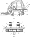
Fig. 1 is a sectional view of a vehicle assembled with a pipeline mounting head and a pipeline structure in the present disclosure. -
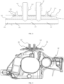
Fig. 2 is a side view of the pipeline mounting head inFig. 1 . -
Fig. 3 is a local sectional view of the assembled pipeline mounting head and vehicle body inFig. 1 . -
Fig. 4 is a sectional view of the assembled pipeline structure and subframe. -
Fig. 5 is a stereogram of the pipeline structure inFig. 1 . - Reference signs: 100-pipeline mounting head; 11-mounting plate; 111-sealing gasket; 112-opening; 12-branch pipeline; 121-bevel bulge; 122-groove; 13-main pipeline; 131-left main pipeline; 132-right main pipeline; 133-connecting part; 134-mounting part; 135-sealing structure; 14-snap-fit member; 141-snap-fit part; 142-gap; 15-positioning pin; 200-pipeline structure; 21-cooling water pipe; 211-corrugated pipe; 212-nylon pipe; 213-fixing bracket; 300-vehicle; 31-vehicle body; 311-sheet metal member; 32-subframe; 321-positioning hole.
- Examples will be explained in detail here, as exemplified in the drawings. When the description below involves the drawings, the same numbers in different drawings represent the same or similar elements unless otherwise indicated. The embodiments described in the following examples do not represent all embodiments consistent with the present disclosure. On the contrary, they are only examples of devices that are consistent with some aspects of the present disclosure as detailed in the attached claims.
- The terms used in the present disclosure are solely for the purpose of describing specific embodiments and are not intended to limit the present disclosure. Unless otherwise defined, the technical terms or scientific terms used in the present disclosure shall have the usual meanings understood by those ordinary skilled in the art in the present disclosure. The words "first", "second" and similar words used in the description and claims of the present disclosure do not indicate any order, quantity or importance, but are used only to distinguish different components. Similarly, such words as "one" or "a" are merely used to represent the existence of at least one member, rather than to limit the number thereof. "Multiple" or "a plurality of" indicates two or more members. Similar words such as "comprise" or "include" indicate that the element or object that appears before "comprise" or "include" covers the element or object listed after "comprise" or "include" and the equivalent thereof, and does not exclude other elements or objects. Similar words such as "connect" or "connected" are not limited to physical or mechanical connections, but can include electrical connection, whether direct or indirect. The singular "a", "said" and "the" used in the description and the attached claims of the present disclosure are also intended to include multiple forms, unless the context clearly indicates other meanings. It should also be understood that the term "and/or" used herein refers to and includes any or all possible combinations of one or more associated listed items.
- As shown in
Fig. 1 , the present disclosure provides apipeline mounting head 100 for a vehicle, and thepipeline mounting head 100 for the vehicle is assembled on avehicle 300 together with apipeline structure 200. Thepipeline mounting head 100 for the vehicle includes amounting plate 11, twobranch pipelines 12 located on one side of themounting plate 11, and amain pipeline 13 located on the other side of themounting plate 11 and communicated with thebranch pipelines 12. When thepipeline mounting head 100 for the vehicle is mounted to avehicle body 31, the twobranch pipelines 12 are located in thevehicle body 31, and themain pipeline 13 is located outside thevehicle body 31. - As shown in
Fig. 2 andFig. 3 , thebranch pipelines 12 are cylindrical. In order to facilitate the installation of thebranch pipelines 12 into thevehicle body 31, eachbranch pipeline 12 is provided with a quick-insert structure or a snap-fit structure. In some embodiments, thebranch pipeline 12 is provided with the quick-insert structure. Specifically, a middle part of thebranch pipeline 12 is provided with at least two bulges. An outer diameter of each of the bulges is greater than a whole outer diameter of thebranch pipeline 12, and agroove 122 is arranged between the bulges. - A bulge at the top of the
branch pipeline 12 is arranged as abevel bulge 121. The bevel of thebevel bulge 121 is formed by extending a surface of thebranch pipeline 12 to the bulge, and the bevel is set to facilitate the quick insertion of thebranch pipeline 12 into thevehicle body 31. In the present embodiment, in order to ensure the insertion effect and the fixing effect after insertion, twogrooves 122 are formed between the bulges on thebranch pipeline 12. In other words, thebranch pipeline 12 can be quickly inserted into thevehicle body 31 by providing thebevel bulge 121 and a plurality ofgrooves 122 on thebranch pipeline 12. In other embodiments, thebranch pipeline 12 is provided with the snap-fit structure to facilitate the coordination between thebranch pipeline 12 and thevehicle body 31. - The
main pipeline 13 is communicated with the twobranch pipelines 12 in a vertical direction. Specifically, themain pipeline 13 includes a leftmain pipeline 131 and a rightmain pipeline 132, and the leftmain pipeline 131 and the rightmain pipeline 132 have a same inner diameter. A connectingpart 133 is arranged between the leftmain pipeline 131 and the rightmain pipeline 132. An inner diameter of the connectingpart 133 is less than the inner diameter of the leftmain pipeline 131 and rightmain pipeline 132. This structure can ensure the liquidity of the coolant inside the entirepipeline mounting head 100 and improve the cooling effect. A mountingpart 134 is arranged at an outlet of the leftmain pipeline 131 and the rightmain pipeline 132 respectively, and a sealingstructure 135 is arranged on the mountingpart 134, which can improve the sealing effect between the mountingpart 134 and a coolingwater pipe 21. - The mounting
plate 11 is provided with an elastically deformable snap-fit member 14, and the snap-fit member 14 and thebranch pipelines 12 are located on a same side of the mountingplate 11. When thepipeline mounting head 100 is mounted on thevehicle body 31, the snap-fit member 14 is used to snap-fit with thevehicle body 31. In the present embodiment, the snap-fit member 14 is provided with a snap-fit part 141, the snap-fit part 141 can generate elastic deformation under stress, and agap 142 is arranged between the snap-fit part 141 and the mountingplate 11. - In another embodiment, the snap-
fit member 14 includes an elastically deformable snap-fit part and a fixed part which is fixed to the mounting plate. The snap-fit part is arranged on the fixed part, and a gap is arranged between a bottom of the snap-fit part and the mountingplate 11. - To ensure the sealing effect, the mounting
plate 11 is provided with a sealinggasket 111, and the sealinggasket 111 is a square frame structure. The sealinggasket 111 is provided with anopening 112 through which the twobranch pipelines 12 and two snap-fit members 14 penetrate. - A lower part of the
main pipeline 13 is provided with apositioning pin 15 which is arranged perpendicular to the mountingplate 11. In the present embodiment, thepositioning pin 15 is fixed on themain pipeline 13 by hot melting. When thepositioning pin 15 is subjected to a force of which a direction is different from directions of forces acting on the mountingplate 11 and themain pipeline 13, thepositioning pin 15 is disconnected from themain pipeline 13. - As shown in
Fig. 5 , the present disclosure provides apipeline structure 200. Thepipeline structure 200 includes thepipeline mounting head 100 for the vehicle and the coolingwater pipe 21 mounted on thepipeline mounting head 100 for the vehicle. Specifically, the coolingwater pipe 21 is mounted on the mountingparts 134 on the left and right ends of themain pipeline 13 by cooperating with the sealingstructure 135. - The cooling
water pipe 21 includes acorrugated pipe 211 and anylon pipe 212 connected with thecorrugated pipe 211, where thecorrugated pipe 211 is connected with the mountingpart 134. Thenylon pipe 212 of the coolingwater pipe 21 is also provided with a fixingbracket 213, and the coolingwater pipe 21 is fixed with asubframe 32 through the fixingbracket 213. - The
pipeline structure 200 is applied to thevehicle 300, and thevehicle 300 is provided with thevehicle body 31 and thesubframe 32 assembled on thevehicle body 31. As shown inFig. 4 , when thepipeline structure 200 is assembled, firstly, thepositioning pin 15 is snapped into apositioning hole 321 on thesubframe 32, and thepipeline mounting head 100 for the vehicle and thesubframe 32 are preliminarily positioned; and then the coolingwater pipe 21 is also fixed to thesubframe 32 through the fixingbracket 213, so that thepipeline mounting head 100 is close to thesubframe 32. A gap exists between the coolingwater pipe 21 and thevehicle body 31. When thesubframe 32 moves relative to thevehicle body 31 in a driving process of the vehicle, the corrugated pipe part of the coolingwater pipe 21 can absorb the movement and play a buffering role. - Subsequently, the
pipeline structure 200 and thesubframe 32 are lifted upward jointly to cooperate with asheet metal member 311 on thevehicle body 31. Thesheet metal member 311 is provided with a fixing hole (not shown) through which the snap-fit member 14 penetrates. An upward pull force is applied to thepipeline structure 200; the snap-fit part 141 of the snap-fit member 14 deforms and penetrates through the fixing hole on thesheet metal member 311; then, the snap-fit member 14 recovers from deformation; and the snap-fit part 141 is snapped with thesheet metal member 311. Thus, the mountingplate 11 is close to thesheet metal member 311. Thesheet metal member 311 compacts the sealinggasket 111 and is snapped into thegap 142 between the snap-fit part 141 and the mountingplate 11. At this moment, the sealinggasket 111 is located between the mountingplate 11 and thesheet metal member 311. - After the
pipeline structure 200 and thesubframe 32 are mounted on thevehicle body 31, a small force is applied to thepositioning pin 15 to disconnect the positioning pin from themain pipeline 13 and fall off. At this moment, a space exists between thepipeline mounting head 100 and thesubframe 32. Provision of thepositioning pin 15 ensures that thepipeline structure 200 and thesubframe 32 can be accurately mounted on thevehicle body 31 and a gap is allowed between thepipeline structure 200 and surrounding components after installation. - The
pipeline mounting head 100, thepipeline structure 200 and thevehicle 300 are provided by the present disclosure. The mountingplate 11 is provided with the snap-fit member 14 and the sealinggasket 111, and the snap-fit member 14 is snapped with thesheet metal member 311 so that thepipeline mounting head 100 can be conveniently mounted on thevehicle body 31 and the fixing effect and the sealing effect can be guaranteed. By mounting thedisconnectable positioning pin 15 on themain pipeline 13, during installation, thepipeline structure 200 can be preliminarily positioned on thesubframe 32 through thepositioning pin 15; then thesubframe 32 and thepipeline structure 200 are mounted on thevehicle body 31 as a whole; and subsequently, a force is applied to thepositioning pin 15 to disconnect thepositioning pin 15 from themain pipeline 13. Thepositioning pin 15 can ensure that thesubframe 32 and thepipeline structure 200 are accurately positioned with the fixing hole of thesheet metal member 311 is to reduce mounting difficulty. - The description only describes preferred embodiments of the present disclosure and is not intended to limit the present disclosure in any form. Any modification, equivalent replacement, improvement, etc. made within the content of the present disclosure shall be included in the protection scope of the present disclosure.
Claims (10)
- A pipeline mounting head for a vehicle, comprising a mounting plate, two branch pipelines located on one side of the mounting plate, and a main pipeline located on the other side of the mounting plate and communicated with the branch pipelines, wherein the mounting plate is provided with a snap-fit member, and the snap-fit member and the branch pipelines are located on the same side of the mounting plate.
- The pipeline mounting head for the vehicle according to claim 1, wherein the snap-fit member is provided with an elastically deformable snap-fit part, and a gap is provided between the snap-fit part and the mounting plate.
- The pipeline mounting head for the vehicle according to claim 1, wherein the mounting plate is provided with a sealing gasket, and a middle of the sealing gasket is provided with an opening through which the branch pipelines and the snap-fit member penetrate.
- The pipeline mounting head for the vehicle according to claim 1, wherein a lower part of the main pipeline is provided with a positioning pin which is perpendicular to the mounting plate, and the positioning pin is disconnected from the main pipeline when stressed.
- A pipeline structure, comprising the pipeline mounting head for the vehicle according to any one of claims 1-4, and further comprising a cooling water pipe connected with the main pipeline.
- The pipeline structure according to claim 5, wherein the cooling water pipe comprises a corrugated pipe and a nylon pipe connected with the corrugated pipe, and the corrugated pipe is connected with both ends of the main pipeline.
- A vehicle, comprising the pipeline structure according to claim 5, and further comprising a vehicle body and a subframe assembled on the vehicle body, wherein after the pipeline structure is assembled on the subframe, the subframe and the pipeline structure are assembled with the vehicle body.
- The vehicle according to claim 7, wherein a sheet metal member of the vehicle body is provided with a fixing hole, the snap-fit member penetrates through the fixing hole and then is snapped on the sheet metal member, the sealing gasket is located between the mounting plate and the sheet metal member, and the sheet metal member is snapped in the gap.
- The vehicle according to claim 8, wherein the cooling water pipe is provided with a fixing bracket, the cooling water pipe is fixed with the subframe through the fixing bracket, the cooling water pipe comprises a corrugated pipe connected with both ends of the main pipeline, and a buffer space exists between the cooling water pipe and the subframe.
- The vehicle according to claim 8, wherein the subframe is provided with a positioning hole matched with the positioning pin, the positioning pin is fixed in the positioning hole before disconnected, and a gap exists between the pipeline joint and the subframe.
Applications Claiming Priority (2)
| Application Number | Priority Date | Filing Date | Title |
|---|---|---|---|
| CN202211204149.2A CN115493012B (en) | 2022-09-29 | 2022-09-29 | Vehicle pipeline installation head, pipeline structure and vehicle |
| PCT/CN2023/107300 WO2024066670A1 (en) | 2022-09-29 | 2023-07-13 | Vehicle pipeline mounting head, pipeline structure and vehicle |
Publications (2)
| Publication Number | Publication Date |
|---|---|
| EP4513074A1 true EP4513074A1 (en) | 2025-02-26 |
| EP4513074A4 EP4513074A4 (en) | 2025-08-20 |
Family
ID=84472052
Family Applications (1)
| Application Number | Title | Priority Date | Filing Date |
|---|---|---|---|
| EP23869917.7A Pending EP4513074A4 (en) | 2022-09-29 | 2023-07-13 | VEHICLE PIPELINE ASSEMBLY HEAD, PIPELINE AND VEHICLE |
Country Status (4)
| Country | Link |
|---|---|
| US (1) | US12535169B2 (en) |
| EP (1) | EP4513074A4 (en) |
| CN (1) | CN115493012B (en) |
| WO (1) | WO2024066670A1 (en) |
Families Citing this family (2)
| Publication number | Priority date | Publication date | Assignee | Title |
|---|---|---|---|---|
| CN115493012B (en) * | 2022-09-29 | 2026-03-03 | 浙江吉利控股集团有限公司 | Vehicle pipeline installation head, pipeline structure and vehicle |
| CN116857297A (en) * | 2023-06-30 | 2023-10-10 | 浙江极氪智能科技有限公司 | Sheath and universal joint |
Family Cites Families (31)
| Publication number | Priority date | Publication date | Assignee | Title |
|---|---|---|---|---|
| US3469863A (en) * | 1967-04-05 | 1969-09-30 | Trico Products Corp | Fluid coupling assembly |
| US4893845A (en) * | 1988-04-18 | 1990-01-16 | Proprietary Technology, Inc. | Firewall heater line adapter |
| IT220447Z2 (en) * | 1990-06-08 | 1993-09-22 | Italiana Serrature Torino | CONNECTION GROUP FOR CIRCUITS OF CIRCULATION OF THE COOLANT LIQUID OF A VEHICLE ENGINE |
| GB2285302B (en) * | 1993-11-08 | 1997-10-15 | F W Talbot & Co Limited | A module |
| JP3638037B2 (en) * | 1995-05-23 | 2005-04-13 | 豊田合成株式会社 | Hose connector |
| JP3508381B2 (en) * | 1996-04-26 | 2004-03-22 | 東海ゴム工業株式会社 | One-touch connection device for focusing hose |
| FR2781311A1 (en) * | 1998-07-16 | 2000-01-21 | Alsthom Cge Alcatel | Fluid conduit for temperature regulation of battery cells comprises modular units for length adjustment |
| US6447023B1 (en) * | 2000-01-27 | 2002-09-10 | Paccar Inc | Air management apparatus and method having manifold and pass-through components |
| US6991270B2 (en) * | 2000-12-27 | 2006-01-31 | Toyoda Gosei, Co., Ltd. | Hose coupling assembly |
| JP4026712B2 (en) * | 2003-03-28 | 2007-12-26 | 関東自動車工業株式会社 | Resin molding die cooling water piping connection device |
| JP4295587B2 (en) * | 2003-09-17 | 2009-07-15 | 本田技研工業株式会社 | Air intake pipe terminal structure |
| FR2913469B1 (en) * | 2007-03-06 | 2010-12-17 | Raymond A & Cie | DEVICE FOR ASSEMBLING TWO PLATES |
| JP5341743B2 (en) * | 2009-12-24 | 2013-11-13 | 豊田合成株式会社 | Pipe holder |
| CN201651564U (en) * | 2010-03-29 | 2010-11-24 | 比亚迪股份有限公司 | Sealing device for pipeline |
| US20120286506A1 (en) * | 2011-05-10 | 2012-11-15 | Mckenzie Daniel | Water manifold |
| JP6321423B2 (en) * | 2014-03-26 | 2018-05-09 | 住友理工株式会社 | Piping fixture |
| CN203907017U (en) * | 2014-06-27 | 2014-10-29 | 安徽江淮汽车股份有限公司 | Cooling water pipe fixed support and cooling water pipe assembly |
| FR3024536B1 (en) | 2014-08-04 | 2019-03-22 | Valeo Systemes Thermiques | CONNECTION AND DISTRIBUTION DEVICE FOR THERMAL BATTERY MANAGEMENT CIRCUIT |
| US20170051853A1 (en) * | 2015-08-18 | 2017-02-23 | Wen-Kuei Wu | Pipe Joint Structure |
| US10351179B2 (en) * | 2017-08-29 | 2019-07-16 | Matt J Schulte | Dual configuration automobile floor assembly |
| IT201800007822A1 (en) * | 2018-08-03 | 2020-02-03 | Nupi Ind Italiane Spa | BLOCK FOR HYDRAULIC-SANITARY USES |
| US11274781B1 (en) * | 2018-12-01 | 2022-03-15 | Orbit Irrigation Products, Llc | Irrigation line couplings and irrigation manifolds including irrigation line couplings |
| CN210707249U (en) * | 2019-09-25 | 2020-06-09 | 北京长城华冠汽车科技股份有限公司 | Snaps for securing vehicle fenders |
| CN210687409U (en) * | 2019-10-30 | 2020-06-05 | 重庆溯联塑胶股份有限公司 | Flange plate for water inlet and outlet |
| CN215111208U (en) * | 2021-01-27 | 2021-12-10 | 诺浩科技(天津)有限公司 | Power battery coolant liquid quick breaking device of electric vehicle |
| CN215410752U (en) * | 2021-04-13 | 2022-01-04 | 珠海吉泰克燃气设备技术有限公司 | Multi-manifold connector |
| CN215522378U (en) * | 2021-05-27 | 2022-01-14 | 广西汽车集团有限公司 | Pipeline connecting device |
| CN214789689U (en) * | 2021-06-01 | 2021-11-19 | 河北亚大汽车塑料制品有限公司 | Multi-way connector used in automobile battery pack |
| US20230420787A1 (en) * | 2022-06-24 | 2023-12-28 | Rivian Ip Holdings, Llc | Battery pack bracket integration |
| US12109912B2 (en) * | 2022-06-29 | 2024-10-08 | Rivian Ip Holdings, Llc | Manifold bracket |
| CN115493012B (en) * | 2022-09-29 | 2026-03-03 | 浙江吉利控股集团有限公司 | Vehicle pipeline installation head, pipeline structure and vehicle |
-
2022
- 2022-09-29 CN CN202211204149.2A patent/CN115493012B/en active Active
-
2023
- 2023-07-13 EP EP23869917.7A patent/EP4513074A4/en active Pending
- 2023-07-13 WO PCT/CN2023/107300 patent/WO2024066670A1/en not_active Ceased
- 2023-07-13 US US18/873,904 patent/US12535169B2/en active Active
Also Published As
| Publication number | Publication date |
|---|---|
| EP4513074A4 (en) | 2025-08-20 |
| WO2024066670A1 (en) | 2024-04-04 |
| CN115493012B (en) | 2026-03-03 |
| US12535169B2 (en) | 2026-01-27 |
| US20250376018A1 (en) | 2025-12-11 |
| CN115493012A (en) | 2022-12-20 |
Similar Documents
| Publication | Publication Date | Title |
|---|---|---|
| EP4513074A1 (en) | Vehicle pipeline mounting head, pipeline structure and vehicle | |
| US11651869B2 (en) | Thermal expansion slide with cable clamp | |
| US6797879B2 (en) | Avionics tray assembly and seal assembly | |
| AU728837B2 (en) | Heat exchanger assembly utilizing grommets and integral cast tanks | |
| CN1993268B (en) | Engine assembly for aircraft | |
| GB2520772A (en) | A powertrain torque roll restrictor | |
| EP4481312A1 (en) | Fixing structure and insertion-plate-type heat exchanger having same | |
| CN208760344U (en) | Pure electric vehicle drive axle structure and drive system | |
| CN109121367B (en) | Electric appliance box heat radiation structure and electric appliance product comprising same | |
| CN210153374U (en) | Battery cooling module flange | |
| CN216993859U (en) | Two-stage vibration isolation suspension device and vehicle | |
| CN208377046U (en) | A kind of aircraft wing body bindiny mechanism | |
| CN112576320B (en) | Air guide sleeve structure capable of coordinating cold and hot state deformation | |
| CN216252092U (en) | Transmission tower quadrangular pyramid cross arm splicing hanging wire node structure | |
| CN213299073U (en) | Braking hard tube connecting piece, braking hard tube device assembly and vehicle | |
| CN215490289U (en) | Heat exchange assembly and air conditioner | |
| CN222512966U (en) | Vacuum coating equipment and its spray components | |
| CN224145892U (en) | Vehicle body and vehicle | |
| CN218972413U (en) | Nitrogen cylinder mounting structure | |
| CN222011216U (en) | Fluid seal flange structure | |
| CN206727311U (en) | Connector assembly and transmission line | |
| CN223639565U (en) | A car cooling module | |
| CN210399669U (en) | Split type heating pipe assembly | |
| CN103471447A (en) | Combined heat exchanger | |
| CN219347494U (en) | Connecting pipe structure of heat exchanger |
Legal Events
| Date | Code | Title | Description |
|---|---|---|---|
| STAA | Information on the status of an ep patent application or granted ep patent |
Free format text: STATUS: THE INTERNATIONAL PUBLICATION HAS BEEN MADE |
|
| PUAI | Public reference made under article 153(3) epc to a published international application that has entered the european phase |
Free format text: ORIGINAL CODE: 0009012 |
|
| STAA | Information on the status of an ep patent application or granted ep patent |
Free format text: STATUS: REQUEST FOR EXAMINATION WAS MADE |
|
| 17P | Request for examination filed |
Effective date: 20241122 |
|
| AK | Designated contracting states |
Kind code of ref document: A1 Designated state(s): AL AT BE BG CH CY CZ DE DK EE ES FI FR GB GR HR HU IE IS IT LI LT LU LV MC ME MK MT NL NO PL PT RO RS SE SI SK SM TR |
|
| REG | Reference to a national code |
Ref country code: DE Ref legal event code: R079 Free format text: PREVIOUS MAIN CLASS: F16L0041020000 Ipc: F16L0005140000 |
|
| A4 | Supplementary search report drawn up and despatched |
Effective date: 20250718 |
|
| RIC1 | Information provided on ipc code assigned before grant |
Ipc: F16L 5/14 20060101AFI20250714BHEP Ipc: F16L 41/03 20060101ALI20250714BHEP |
|
| RAP1 | Party data changed (applicant data changed or rights of an application transferred) |
Owner name: ZHEJIANG GEELY HOLDING GROUP CO., LTD. Owner name: ZHEJIANG LIANKONG TECHNOLOGIES CO., LTD. |
|
| DAV | Request for validation of the european patent (deleted) | ||
| DAX | Request for extension of the european patent (deleted) |