EP4513067A1 - Solenoid valve and coil thereof, and housing of coil - Google Patents
Solenoid valve and coil thereof, and housing of coil Download PDFInfo
- Publication number
- EP4513067A1 EP4513067A1 EP23791107.8A EP23791107A EP4513067A1 EP 4513067 A1 EP4513067 A1 EP 4513067A1 EP 23791107 A EP23791107 A EP 23791107A EP 4513067 A1 EP4513067 A1 EP 4513067A1
- Authority
- EP
- European Patent Office
- Prior art keywords
- housing
- solenoid valve
- heat dissipation
- coil
- arc
- Prior art date
- Legal status (The legal status is an assumption and is not a legal conclusion. Google has not performed a legal analysis and makes no representation as to the accuracy of the status listed.)
- Pending
Links
Images


Classifications
-
- F—MECHANICAL ENGINEERING; LIGHTING; HEATING; WEAPONS; BLASTING
- F16—ENGINEERING ELEMENTS AND UNITS; GENERAL MEASURES FOR PRODUCING AND MAINTAINING EFFECTIVE FUNCTIONING OF MACHINES OR INSTALLATIONS; THERMAL INSULATION IN GENERAL
- F16K—VALVES; TAPS; COCKS; ACTUATING-FLOATS; DEVICES FOR VENTING OR AERATING
- F16K49/00—Means in or on valves for heating or cooling
-
- F—MECHANICAL ENGINEERING; LIGHTING; HEATING; WEAPONS; BLASTING
- F16—ENGINEERING ELEMENTS AND UNITS; GENERAL MEASURES FOR PRODUCING AND MAINTAINING EFFECTIVE FUNCTIONING OF MACHINES OR INSTALLATIONS; THERMAL INSULATION IN GENERAL
- F16K—VALVES; TAPS; COCKS; ACTUATING-FLOATS; DEVICES FOR VENTING OR AERATING
- F16K27/00—Construction of housing; Use of materials therefor
- F16K27/02—Construction of housing; Use of materials therefor of lift valves
- F16K27/029—Electromagnetically actuated valves
-
- F—MECHANICAL ENGINEERING; LIGHTING; HEATING; WEAPONS; BLASTING
- F16—ENGINEERING ELEMENTS AND UNITS; GENERAL MEASURES FOR PRODUCING AND MAINTAINING EFFECTIVE FUNCTIONING OF MACHINES OR INSTALLATIONS; THERMAL INSULATION IN GENERAL
- F16K—VALVES; TAPS; COCKS; ACTUATING-FLOATS; DEVICES FOR VENTING OR AERATING
- F16K31/00—Actuating devices; Operating means; Releasing devices
- F16K31/02—Actuating devices; Operating means; Releasing devices electric; magnetic
- F16K31/06—Actuating devices; Operating means; Releasing devices electric; magnetic using a magnet, e.g. diaphragm valves, cutting off by means of a liquid
- F16K31/0675—Electromagnet aspects, e.g. electric supply therefor
-
- H—ELECTRICITY
- H01—ELECTRIC ELEMENTS
- H01F—MAGNETS; INDUCTANCES; TRANSFORMERS; SELECTION OF MATERIALS FOR THEIR MAGNETIC PROPERTIES
- H01F27/00—Details of transformers or inductances, in general
- H01F27/02—Casings
- H01F27/025—Constructional details relating to cooling
-
- H—ELECTRICITY
- H01—ELECTRIC ELEMENTS
- H01F—MAGNETS; INDUCTANCES; TRANSFORMERS; SELECTION OF MATERIALS FOR THEIR MAGNETIC PROPERTIES
- H01F27/00—Details of transformers or inductances, in general
- H01F27/08—Cooling; Ventilating
- H01F27/22—Cooling by heat conduction through solid or powdered fillings
-
- H—ELECTRICITY
- H01—ELECTRIC ELEMENTS
- H01F—MAGNETS; INDUCTANCES; TRANSFORMERS; SELECTION OF MATERIALS FOR THEIR MAGNETIC PROPERTIES
- H01F7/00—Magnets
- H01F7/06—Electromagnets; Actuators including electromagnets
- H01F7/08—Electromagnets; Actuators including electromagnets with armatures
- H01F7/128—Encapsulating, encasing or sealing
Definitions
- the present disclosure relates to the technical field of solenoid valves, and particularly, to a solenoid valve, a coil thereof, and a housing of the coil.
- a solenoid valve is a valve device that controls fluid communication or blocking by powering the coil on or off.
- the solenoid valve is equipped with a coil, an iron core and a piston, and the iron core is controlled to drive the movement of the piston by using the changing magnetic field generated by powering the coil on or off, so as to communicate or block the inlet and outlet, thereby achieving control of the fluid.
- Embodiments of the present disclosure provide a solenoid valve, a coil thereof, and a housing of the coil, which can improve the heat dissipation performance of the coil.
- the housing of the solenoid valve coil in the embodiment of the present disclosure includes a body and a heat dissipation structure.
- the body has a cavity, and the cavity is used to accommodate a coil part of the solenoid valve coil; an outer wall surface of the body has an arc-shaped surface; the heat dissipation structure is integrally provided on the arc-shaped surface of the housing; where the heat dissipation structure is concave and/or convex on the arc-shaped surface.
- the solenoid valve in the embodiment of the present disclosure includes the solenoid valve coil described in any one of the above.
- One embodiment in the above disclosure has at least the following advantages or beneficial effects.
- the arc-shaped surface of the body is integrally provided with a heat dissipation structure, and the heat-dissipation structure is concave or convex on the arc-shaped surface of the body, thereby increasing the surface area of the outer wall surface of the housing, and thus improving the heat dissipation performance of the housing when the coil is working.
- FIG. 1 shows a schematic three-dimensional view of a housing 100 of a solenoid valve coil according to an embodiment of the present disclosure
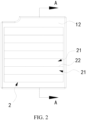
- FIG. 2 shows a side view of the housing 100 of the solenoid valve coil according to the embodiment of the present disclosure
- FIG. 3 shows a cross-sectional view along line A-A in FIG. 2
- the housing 100 of the solenoid valve coil in the embodiment of the present disclosure includes a body 1 and a heat dissipation structure 2.
- the body 1 has a cavity 11, and the cavity 11 is used to accommodate a coil part (not shown in the figure) of the solenoid valve coil.
- the outer wall surface of the body 1 has an arc-shaped surface 12.
- the heat dissipation structure 2 is integrally provided on the arc-shaped surface 12 of the housing 100.
- the heat dissipation structure 2 is concave and/or convex on the arc-shaped surface 12.
- the arc-shaped surface 12 of the body 1 is integrally provided with a heat dissipation structure 2, and the heat dissipation structure 2 is concave or convex on the arc-shaped surface 12 of the body 1. Therefore, the surface area of the outer wall surface of the housing 100 is increased, thereby improving the heat dissipation performance of the housing 100 when the coil is operating.
- the heat dissipation structure 2 is concave on the arc-shaped surface 12 of the body 1.
- the arc-shaped surface 12 on the side of the body 1 with the heat dissipation structure 2 does not protrude from the surface of the body 1, that is, the heat dissipation structure 2 does not increase the outer contour of the body 1, and the heat dissipation structure 2 will not affect the installation of other component(s).
- the heat dissipation structure 2 may also protrude from the arc-shaped surface 12 of the body 1.
- the heat dissipation structure 2 When the heat dissipation structure 2 is concave on the arc-shaped surface 12 of the body 1, the heat dissipation structure 2 may be a groove, a pit, or other structures. When the heat dissipation structure 2 is convex on the arc-shaped surface 12 of the body 1, the heat dissipation structure 2 may be a protrusion, a bump, a boss, or other structures.
- the heat dissipation structure 2 is concave or convex on the arc-shaped surface 12 of the body 1, it can increase the surface area of the outer wall surface of the housing 100, thereby allowing the heat inside the housing 100 to dissipate outward through the heat dissipation structure 2, so as to improve the overall heat dissipation performance of the housing 100.
- the body 1 has two opposite arc-shaped surfaces 12, and each arc-shaped surface 12 is provided with the heat dissipation structure 2.
- each arc-shaped surface 12 is provided with the heat dissipation structure 2.
- the housing 100 of the embodiment of the present disclosure only has two opposite arc-shaped surfaces 12, while the other surfaces of the body 1 are all flat surfaces. This design is because the remaining flat surfaces are for fitting and installation with other component(s), and the heat dissipation structure 2 is not provided on the flat surfaces of the body 1 to avoid affecting the fitting and installation of the housing 100 with other components.
- the heat dissipation structure 2 includes a plurality of grooves 21 arranged side by side.
- each groove 21 is elongated.
- the direction in which the plurality of grooves 21 are arranged side by side is along the width direction of the grooves 21.
- the shape of the groove 21 may also be circular, rectangular, other polygonal, etc.
- the plurality of grooves 21 may also be arranged in an array on the arc-shaped surface 12 of the body 1.
- the heat dissipation structure 2 may include a plurality of grooves 21 with different shapes and/or sizes.
- Two adjacent grooves 21 are adjoined and form a boundary ridge 22.
- the groove walls 211 of two adjacent grooves 21 are directly connected and intersect at the boundary ridge 22.
- the arc-shaped surface 12 can be arranged with as many grooves 21 as possible to maximize the surface area of the outer wall of the housing 100.
- each groove 21 may have various shapes, such as a curved surface, a flat surface, or a combination of a flat surface and a curved surface.
- each groove 21 is circular-arc-shaped. In this way, the plurality of grooves 21 arranged side by side can form a wavy heat dissipation structure 2.
- the heat dissipation structure 2 and the body 1 are integrally injection molded.
- the heat dissipation structure 2 and the body 1 are integrally injection molded, which makes the processing of the heat dissipation structure 2 more convenient and avoids difficulty in molding the heat dissipation structure 2 due to the brittle material of the body 1.
- the integrated injection molding can also save materials and reduce material costs.
- the depth t here refers to a distance between the lowest point of the groove wall 211 of the groove 21 and the corresponding arc-shaped surface 12 of the groove 21.
Landscapes
- Engineering & Computer Science (AREA)
- General Engineering & Computer Science (AREA)
- Power Engineering (AREA)
- Physics & Mathematics (AREA)
- Electromagnetism (AREA)
- Mechanical Engineering (AREA)
- Electromagnets (AREA)
Abstract
Description
- The present disclosure claims the priority of the
Chinese patent application with application number 202220897073.5, titled "SOLENOID VALVE AND COIL THEREOF, AND HOUSING OF COIL", and filed on April 18, 2022 - The present disclosure relates to the technical field of solenoid valves, and particularly, to a solenoid valve, a coil thereof, and a housing of the coil.
- A solenoid valve is a valve device that controls fluid communication or blocking by powering the coil on or off. The solenoid valve is equipped with a coil, an iron core and a piston, and the iron core is controlled to drive the movement of the piston by using the changing magnetic field generated by powering the coil on or off, so as to communicate or block the inlet and outlet, thereby achieving control of the fluid.
- When the solenoid valve is working, a certain amount of heat will be generated after the coil is powered on. However, the heat dissipation effect of the solenoid valve coil in the related art is poor, which affects the normal operation of the solenoid valve.
- Embodiments of the present disclosure provide a solenoid valve, a coil thereof, and a housing of the coil, which can improve the heat dissipation performance of the coil.
- The housing of the solenoid valve coil in the embodiment of the present disclosure includes a body and a heat dissipation structure. The body has a cavity, and the cavity is used to accommodate a coil part of the solenoid valve coil; an outer wall surface of the body has an arc-shaped surface; the heat dissipation structure is integrally provided on the arc-shaped surface of the housing; where the heat dissipation structure is concave and/or convex on the arc-shaped surface.
- The solenoid valve in the embodiment of the present disclosure includes the solenoid valve coil described in any one of the above.
- One embodiment in the above disclosure has at least the following advantages or beneficial effects.
- In the housing of the solenoid valve coil in the embodiments of the present disclosure, the arc-shaped surface of the body is integrally provided with a heat dissipation structure, and the heat-dissipation structure is concave or convex on the arc-shaped surface of the body, thereby increasing the surface area of the outer wall surface of the housing, and thus improving the heat dissipation performance of the housing when the coil is working.
-
-
FIG. 1 shows a schematic three-dimensional view of a housing of a solenoid valve coil according to an embodiment of the present disclosure. -
FIG. 2 shows a side view of the housing of the solenoid valve coil according to the embodiment of the present disclosure. -
FIG. 3 shows a cross-sectional view along line A-A inFIG. 2 . - The reference signs are explained as follows:
- 100. Housing
- 1. Body
- 11. Cavity
- 12. Arc-shaped surface
- 13. First opening
- 2. Heat dissipation structure
- 21. Groove
- 211. Groove wall
- 22. Boundary ridge
- t. Depth
- Exemplary implementations will now be described more fully with reference to the accompanying drawings. Exemplary implementations may, however, be embodied in many forms and should not be construed as limited to the implementations set forth herein; rather, these implementations are provided so that the present disclosure will be thorough and complete, and will fully convey the concept of the exemplary implementations to those skilled in the art. The same reference signs in the drawings denote the same or similar structures, and thus their detailed descriptions will be omitted.
- As shown in
FIGs. 1 to 3 ,FIG. 1 shows a schematic three-dimensional view of ahousing 100 of a solenoid valve coil according to an embodiment of the present disclosure,FIG. 2 shows a side view of thehousing 100 of the solenoid valve coil according to the embodiment of the present disclosure, andFIG. 3 shows a cross-sectional view along line A-A inFIG. 2 . Thehousing 100 of the solenoid valve coil in the embodiment of the present disclosure includes abody 1 and aheat dissipation structure 2. Thebody 1 has acavity 11, and thecavity 11 is used to accommodate a coil part (not shown in the figure) of the solenoid valve coil. The outer wall surface of thebody 1 has an arc-shaped surface 12. Theheat dissipation structure 2 is integrally provided on the arc-shaped surface 12 of thehousing 100. Theheat dissipation structure 2 is concave and/or convex on the arc-shaped surface 12. - In the
housing 100 of the solenoid valve coil in the embodiment of the present disclosure, the arc-shaped surface 12 of thebody 1 is integrally provided with aheat dissipation structure 2, and theheat dissipation structure 2 is concave or convex on the arc-shaped surface 12 of thebody 1. Therefore, the surface area of the outer wall surface of thehousing 100 is increased, thereby improving the heat dissipation performance of thehousing 100 when the coil is operating. - It will be understood that the terms "include" and "have" in the embodiments of the present disclosure, as well as any variations thereof, are intended to cover non-exclusive inclusion. For example, a process, method, system, product or device that contains a series of steps or units is not limited to the listed steps or units, but may optionally also include steps or units that are not listed, or may optionally also include other steps or components inherent to these processes, methods, products or devices.
- Continuing to refer to
FIGs. 1 to 3 , in this embodiment, theheat dissipation structure 2 is concave on the arc-shaped surface 12 of thebody 1. Through the design of theheat dissipation structure 2 being concave on the arc-shaped surface 12 of thebody 1, the arc-shaped surface 12 on the side of thebody 1 with theheat dissipation structure 2 does not protrude from the surface of thebody 1, that is, theheat dissipation structure 2 does not increase the outer contour of thebody 1, and theheat dissipation structure 2 will not affect the installation of other component(s). - It can be understood that in other implementations, the
heat dissipation structure 2 may also protrude from the arc-shaped surface 12 of thebody 1. - When the
heat dissipation structure 2 is concave on the arc-shaped surface 12 of thebody 1, theheat dissipation structure 2 may be a groove, a pit, or other structures. When theheat dissipation structure 2 is convex on the arc-shaped surface 12 of thebody 1, theheat dissipation structure 2 may be a protrusion, a bump, a boss, or other structures. - It can be understood that whether the
heat dissipation structure 2 is concave or convex on the arc-shaped surface 12 of thebody 1, it can increase the surface area of the outer wall surface of thehousing 100, thereby allowing the heat inside thehousing 100 to dissipate outward through theheat dissipation structure 2, so as to improve the overall heat dissipation performance of thehousing 100. - In this embodiment, the
body 1 has two opposite arc-shaped surfaces 12, and each arc-shaped surface 12 is provided with theheat dissipation structure 2. By disposing theheat dissipation structure 2 on each arc-shaped surface 12, the surface area of the outer wall of thehousing 100 is further increased, and the heat dissipation performance is further improved. - It should be noted that the
housing 100 of the embodiment of the present disclosure only has two opposite arc-shaped surfaces 12, while the other surfaces of thebody 1 are all flat surfaces. This design is because the remaining flat surfaces are for fitting and installation with other component(s), and theheat dissipation structure 2 is not provided on the flat surfaces of thebody 1 to avoid affecting the fitting and installation of thehousing 100 with other components. - Continuing to refer to
FIGs. 1 to 3 , theheat dissipation structure 2 includes a plurality ofgrooves 21 arranged side by side. - In this embodiment, each
groove 21 is elongated. The direction in which the plurality ofgrooves 21 are arranged side by side is along the width direction of thegrooves 21. - It can be understood that in some implementations, the shape of the
groove 21 may also be circular, rectangular, other polygonal, etc. In addition, the plurality ofgrooves 21 may also be arranged in an array on the arc-shapedsurface 12 of thebody 1. - Alternatively, in some implementations, the
heat dissipation structure 2 may include a plurality ofgrooves 21 with different shapes and/or sizes. - Two
adjacent grooves 21 are adjoined and form aboundary ridge 22. In other words, thegroove walls 211 of twoadjacent grooves 21 are directly connected and intersect at theboundary ridge 22. Through the design of adjoining the plurality ofgrooves 21, the arc-shapedsurface 12 can be arranged with asmany grooves 21 as possible to maximize the surface area of the outer wall of thehousing 100. - The
groove wall 211 of eachgroove 21 may have various shapes, such as a curved surface, a flat surface, or a combination of a flat surface and a curved surface. - In this embodiment, the shape of the
groove wall 211 of eachgroove 21 is circular-arc-shaped. In this way, the plurality ofgrooves 21 arranged side by side can form a wavyheat dissipation structure 2. - In some implementations, the plurality of
grooves 21 arranged side by side may also form a zigzag-shapedheat dissipation structure 2. - The
heat dissipation structure 2 and thebody 1 are integrally injection molded. Theheat dissipation structure 2 and thebody 1 are integrally injection molded, which makes the processing of theheat dissipation structure 2 more convenient and avoids difficulty in molding theheat dissipation structure 2 due to the brittle material of thebody 1. In addition, when theheat dissipation structure 2 is concave on the arc-shapedsurface 12 of thebody 1, the integrated injection molding can also save materials and reduce material costs. - A
first opening 13 and a second opening (not shown in the figure) are respectively provided on two opposite sides of thebody 1. Thefirst opening 13 and the second opening are respectively connected with thecavity 11, and the axis of thefirst opening 13 coincides with the axis of the second opening. Eachgroove 21 is elongated, and the extending direction of thegroove 21 is parallel to the axis of thefirst opening 13. - It should be noted that the
first opening 13 and the second opening of thebody 1 can be used for other component(s) to pass through, such as a conduit with an iron core, etc. In this embodiment, the extending direction of thegroove 21 is designed to be parallel to the axis direction of thefirst opening 13, which makes it easier to demold thehousing 100 after injection molding. - The depth t of the
groove 21 is 0.2-0.7mm, such as 0.3, 0.4, 0.5, 0.6mm. Further, the depth t of thegroove 21 is 0.3-0.7 mm. - It can be understood that the depth t here refers to a distance between the lowest point of the
groove wall 211 of thegroove 21 and the corresponding arc-shapedsurface 12 of thegroove 21. - As an example, when the
housing 100 is not provided with theheat dissipation structure 2, the surface area of the arc-shapedsurface 12 of thehousing 100 is 1400 mm2. When other dimensions of the arc-shapedsurface 12 remain unchanged and the depth t of thegroove 21 is in the range of 0.2-0.7mm, the surface area of the arc-shapedsurface 12 increases to 1540mm2. It can be seen that the surface area of the arc-shapedsurface 12 with theheat dissipation structure 2 is increased by about 10% compared with the original surface area. The increase in the surface area can not only improve the heat dissipation performance, but also reduce the material costs. - Another aspect of the present disclosure also provides a solenoid valve coil, including any of the
above housings 100 of the solenoid valve coil and a coil part. The coil part is packaged in thecavity 11 of thehousing 100. The coil part may include a coil, a coil bobbin, an iron core, etc. - In yet another aspect of the present disclosure, a solenoid valve is provided, including the above-mentioned solenoid valve coil.
- Since the
housing 100 of the solenoid valve coil of any of the above embodiments is included, the solenoid valve and its coil of the embodiments of the present disclosure have all the advantages and beneficial effects of any of the above embodiments, which will not be described again here. - It can be understood that the various embodiments/implementations provided by the present disclosure can be combined with each other if there is no conflict, and examples will not be given here one by one.
- In summary, the advantages and beneficial effects of the solenoid valve, its coil, and the
housing 100 of the coil according to the embodiments of the present disclosure at least include:
the arc-shapedsurface 12 of thebody 1 is integrally provided with aheat dissipation structure 2, theheat dissipation structure 2 is concave or convex on the arc-shapedsurface 12 of thebody 1, thereby increasing the surface area of the outer wall surface of thehousing 100, and improving the heat dissipation performance of thehousing 100 when the coil operates. - In the disclosed embodiments, the terms "first", "second", and "third" are used for descriptive purposes only, and should not be construed as indicating or implying relative importance; the term "a plurality of" refers to two or more than two, unless otherwise expressly limited. The terms "install", "connected", "connection", "fixed" and other terms should be interpreted in a broad sense, for example, "connection" may be a fixed connection, a detachable connection, or an integral connection; "connected" may be directly connected or indirectly connected through an intermediary. Those of ordinary skill in the art can understand the specific meanings of the above terms in the disclosed embodiments according to specific situations.
- In the description of the disclosed embodiments, it should be understood that the orientations or positional relationships indicated by the terms "upper", "lower", "left", "right", "front", "rear" are based on the orientations or positional relationships shown in the accompanying drawings, which are only for the convenience of describing the disclosed embodiments and simplifying the description, and does not indicate or imply that the referred apparatus or unit must have a specific orientation, or be constructed and operated in a specific orientation, and therefore, they cannot be construed as a limitation to the disclosed embodiments.
- In the description of this specification, descriptions of the terms "one embodiment", "some embodiments", "specific embodiment" and the like mean that specific features, structures, materials, or characteristics described in connection with the embodiments or examples are included in at least one embodiment or example of the disclosed embodiments. In this specification, schematic representations of the above terms do not necessarily refer to the same embodiment or example. Furthermore, the specific features, structures, materials or characteristics described may be combined in any suitable manner in any one or more embodiments or examples.
- The above are only preferred embodiments of the disclosed embodiments, and are not intended to limit the disclosed embodiments. For those skilled in the art, various modifications and changes may be made to the disclosed embodiments. Any modifications, equivalent replacements, improvements, etc. made within the spirit and principle of the disclosed embodiments shall be included in the protection scope of the disclosed embodiments.
Claims (10)
- A housing of a solenoid valve coil, comprising:a body having a cavity, wherein the cavity is used to accommodate a coil part of the solenoid valve coil; an outer wall surface of the body has an arc-shaped surface; anda heat dissipation structure integrally provided on the arc-shaped surface of the housing;wherein the heat dissipation structure is concave and/or convex on the arc-shaped surface.
- The housing of the solenoid valve coil according to claim 1, wherein the heat dissipation structure comprises a plurality of grooves arranged side by side.
- The housing of the solenoid valve coil according to claim 2, wherein two adjacent grooves are adjoined and form a boundary ridge.
- The housing of the solenoid valve coil according to claim 2, wherein a groove wall of each of the grooves is circular-arc-shaped.
- The housing of the solenoid valve coil according to claim 2, wherein two opposite sides of the body are respectively provided with a first opening and a second opening, the first opening and the second opening are respectively communicated with the cavity, and an axis of the first opening coincides with an axis of the second opening;
an extending direction of each of the grooves is parallel to the axis of the first opening. - The housing of the solenoid valve coil according to claim 2, wherein a depth of the groove is 0.2-0.7 mm.
- The housing of the solenoid valve coil according to claim 6, wherein the depth of the groove is 0.3-0.7 mm.
- The housing of the solenoid valve coil according to claim 1, wherein the heat dissipation structure and the body are integrally injection molded.
- A solenoid valve coil, comprising:the housing of the solenoid valve coil according to any one of claims 1 to 8; anda coil part packaged in the cavity of the housing.
- A solenoid valve, comprising the solenoid valve coil according to any one of claims 1 to 9.
Applications Claiming Priority (2)
| Application Number | Priority Date | Filing Date | Title |
|---|---|---|---|
| CN202220897073.5U CN217081611U (en) | 2022-04-18 | 2022-04-18 | Solenoid valve and its coil, the casing of the coil |
| PCT/CN2023/087975 WO2023202452A1 (en) | 2022-04-18 | 2023-04-13 | Solenoid valve and coil thereof, and housing of coil |
Publications (2)
| Publication Number | Publication Date |
|---|---|
| EP4513067A1 true EP4513067A1 (en) | 2025-02-26 |
| EP4513067A4 EP4513067A4 (en) | 2025-07-16 |
Family
ID=82498754
Family Applications (1)
| Application Number | Title | Priority Date | Filing Date |
|---|---|---|---|
| EP23791107.8A Pending EP4513067A4 (en) | 2022-04-18 | 2023-04-13 | SOLENOID VALVE AND COIL AS WELL AS HOUSING FOR THE COIL |
Country Status (3)
| Country | Link |
|---|---|
| EP (1) | EP4513067A4 (en) |
| CN (1) | CN217081611U (en) |
| WO (1) | WO2023202452A1 (en) |
Families Citing this family (1)
| Publication number | Priority date | Publication date | Assignee | Title |
|---|---|---|---|---|
| CN217081611U (en) * | 2022-04-18 | 2022-07-29 | 盾安环境技术有限公司 | Solenoid valve and its coil, the casing of the coil |
Family Cites Families (7)
| Publication number | Priority date | Publication date | Assignee | Title |
|---|---|---|---|---|
| US3818398A (en) * | 1971-11-30 | 1974-06-18 | Sporlan Valve Co | Electromagnet coil assembly |
| JP3749026B2 (en) * | 1998-11-27 | 2006-02-22 | 三菱電機株式会社 | Solenoid valve fixing device |
| JP5948792B2 (en) * | 2011-10-27 | 2016-07-06 | アイシン精機株式会社 | Exhaust drain valve for fuel cell |
| CN205896142U (en) * | 2016-08-10 | 2017-01-18 | 江苏金润汽车传动科技有限公司 | Automatic derailleur solenoid valve |
| CN209180464U (en) * | 2018-11-06 | 2019-07-30 | 浙江盾安禾田金属有限公司 | Electromagnetic coil fixes device |
| DE102019004597A1 (en) * | 2019-07-04 | 2021-01-07 | Aventics Gmbh | magnetic valve |
| CN217081611U (en) * | 2022-04-18 | 2022-07-29 | 盾安环境技术有限公司 | Solenoid valve and its coil, the casing of the coil |
-
2022
- 2022-04-18 CN CN202220897073.5U patent/CN217081611U/en active Active
-
2023
- 2023-04-13 EP EP23791107.8A patent/EP4513067A4/en active Pending
- 2023-04-13 WO PCT/CN2023/087975 patent/WO2023202452A1/en not_active Ceased
Also Published As
| Publication number | Publication date |
|---|---|
| CN217081611U (en) | 2022-07-29 |
| WO2023202452A1 (en) | 2023-10-26 |
| EP4513067A4 (en) | 2025-07-16 |
Similar Documents
| Publication | Publication Date | Title |
|---|---|---|
| EP3115612B1 (en) | Electrically driven pump and method for manufacturing the same | |
| EP3121937B1 (en) | Electrically driven pump and method for manufacturing the same | |
| EP4513067A1 (en) | Solenoid valve and coil thereof, and housing of coil | |
| EP4279773A1 (en) | Valve device | |
| US7114921B2 (en) | Fan and blower unit having the same | |
| EP2413476A1 (en) | Stator | |
| EP3859951B1 (en) | Motor housing assembly | |
| CA2149082A1 (en) | Extended range regenerative pump | |
| EP4212710B1 (en) | Fluid adjusting device | |
| KR102162740B1 (en) | Motor operated compressor | |
| EP3690207A1 (en) | Cooling module and intelligent vehicle cooling system | |
| WO2006072109A3 (en) | Systems for low cost liquid cooling | |
| KR20190121686A (en) | System for connecting housing elements of a device for heat transfer | |
| CN216618640U (en) | Fluid regulating device | |
| KR102093892B1 (en) | Heat exchanger for an internal combustion engine | |
| EP4063655B1 (en) | Pump | |
| JP2025012087A (en) | Cooling Module | |
| US20230396105A1 (en) | Cooling structure for disc-type motor | |
| CN111794943B (en) | Compressor cylinder head assembly, compressor and refrigeration equipment | |
| CN211285769U (en) | Excavator hydraulic oil heat abstractor | |
| JP2018013097A (en) | Compressor | |
| CN211009996U (en) | Multi-valve device for vehicle | |
| CN210510548U (en) | High-efficient conveying connecting device of cooler | |
| CN223843605U (en) | Oil-cooled motor stator structure and oil-cooled motor | |
| CN214577641U (en) | Piezoelectric mechanism, piezoelectric valve, and piezoelectric pump |
Legal Events
| Date | Code | Title | Description |
|---|---|---|---|
| STAA | Information on the status of an ep patent application or granted ep patent |
Free format text: STATUS: THE INTERNATIONAL PUBLICATION HAS BEEN MADE |
|
| PUAI | Public reference made under article 153(3) epc to a published international application that has entered the european phase |
Free format text: ORIGINAL CODE: 0009012 |
|
| STAA | Information on the status of an ep patent application or granted ep patent |
Free format text: STATUS: REQUEST FOR EXAMINATION WAS MADE |
|
| 17P | Request for examination filed |
Effective date: 20241031 |
|
| AK | Designated contracting states |
Kind code of ref document: A1 Designated state(s): AL AT BE BG CH CY CZ DE DK EE ES FI FR GB GR HR HU IE IS IT LI LT LU LV MC ME MK MT NL NO PL PT RO RS SE SI SK SM TR |
|
| A4 | Supplementary search report drawn up and despatched |
Effective date: 20250617 |
|
| RIC1 | Information provided on ipc code assigned before grant |
Ipc: F16K 31/06 20060101AFI20250611BHEP Ipc: F16K 27/00 20060101ALI20250611BHEP Ipc: F16K 49/00 20060101ALI20250611BHEP Ipc: H01F 7/08 20060101ALI20250611BHEP Ipc: H01F 27/02 20060101ALI20250611BHEP Ipc: H01F 27/22 20060101ALI20250611BHEP Ipc: H01F 7/128 20060101ALI20250611BHEP |
|
| DAV | Request for validation of the european patent (deleted) | ||
| DAX | Request for extension of the european patent (deleted) |