EP4513036A1 - Operation recording system, vehicle, operation recording method and operation recording program - Google Patents
Operation recording system, vehicle, operation recording method and operation recording program Download PDFInfo
- Publication number
- EP4513036A1 EP4513036A1 EP23811370.8A EP23811370A EP4513036A1 EP 4513036 A1 EP4513036 A1 EP 4513036A1 EP 23811370 A EP23811370 A EP 23811370A EP 4513036 A1 EP4513036 A1 EP 4513036A1
- Authority
- EP
- European Patent Office
- Prior art keywords
- information
- inverter circuit
- operation recording
- abnormality
- time
- Prior art date
- Legal status (The legal status is an assumption and is not a legal conclusion. Google has not performed a legal analysis and makes no representation as to the accuracy of the status listed.)
- Withdrawn
Links
Images



Classifications
-
- F—MECHANICAL ENGINEERING; LIGHTING; HEATING; WEAPONS; BLASTING
- F04—POSITIVE - DISPLACEMENT MACHINES FOR LIQUIDS; PUMPS FOR LIQUIDS OR ELASTIC FLUIDS
- F04B—POSITIVE-DISPLACEMENT MACHINES FOR LIQUIDS; PUMPS
- F04B49/00—Control, e.g. of pump delivery, or pump pressure of, or safety measures for, machines, pumps, or pumping installations, not otherwise provided for, or of interest apart from, groups F04B1/00 - F04B47/00
- F04B49/10—Other safety measures
-
- H—ELECTRICITY
- H02—GENERATION; CONVERSION OR DISTRIBUTION OF ELECTRIC POWER
- H02P—CONTROL OR REGULATION OF ELECTRIC MOTORS, ELECTRIC GENERATORS OR DYNAMO-ELECTRIC CONVERTERS; CONTROLLING TRANSFORMERS, REACTORS OR CHOKE COILS
- H02P29/00—Arrangements for regulating or controlling electric motors, appropriate for both AC and DC motors
- H02P29/02—Providing protection against overload without automatic interruption of supply
- H02P29/024—Detecting a fault condition, e.g. short circuit, locked rotor, open circuit or loss of load
-
- B—PERFORMING OPERATIONS; TRANSPORTING
- B60—VEHICLES IN GENERAL
- B60H—ARRANGEMENTS OF HEATING, COOLING, VENTILATING OR OTHER AIR-TREATING DEVICES SPECIALLY ADAPTED FOR PASSENGER OR GOODS SPACES OF VEHICLES
- B60H1/00—Heating, cooling or ventilating devices
- B60H1/00642—Control systems or circuits; Control members or indication devices for heating, cooling or ventilating devices
- B60H1/00814—Control systems or circuits characterised by their output, for controlling particular components of the heating, cooling or ventilating installation
- B60H1/00878—Control systems or circuits characterised by their output, for controlling particular components of the heating, cooling or ventilating installation the components being temperature regulating devices
-
- F—MECHANICAL ENGINEERING; LIGHTING; HEATING; WEAPONS; BLASTING
- F04—POSITIVE - DISPLACEMENT MACHINES FOR LIQUIDS; PUMPS FOR LIQUIDS OR ELASTIC FLUIDS
- F04B—POSITIVE-DISPLACEMENT MACHINES FOR LIQUIDS; PUMPS
- F04B35/00—Piston pumps specially adapted for elastic fluids and characterised by the driving means to their working members, or by combination with, or adaptation to, specific driving engines or motors, not otherwise provided for
- F04B35/04—Piston pumps specially adapted for elastic fluids and characterised by the driving means to their working members, or by combination with, or adaptation to, specific driving engines or motors, not otherwise provided for the means being electric
-
- F—MECHANICAL ENGINEERING; LIGHTING; HEATING; WEAPONS; BLASTING
- F04—POSITIVE - DISPLACEMENT MACHINES FOR LIQUIDS; PUMPS FOR LIQUIDS OR ELASTIC FLUIDS
- F04B—POSITIVE-DISPLACEMENT MACHINES FOR LIQUIDS; PUMPS
- F04B49/00—Control, e.g. of pump delivery, or pump pressure of, or safety measures for, machines, pumps, or pumping installations, not otherwise provided for, or of interest apart from, groups F04B1/00 - F04B47/00
- F04B49/06—Control using electricity
-
- F—MECHANICAL ENGINEERING; LIGHTING; HEATING; WEAPONS; BLASTING
- F04—POSITIVE - DISPLACEMENT MACHINES FOR LIQUIDS; PUMPS FOR LIQUIDS OR ELASTIC FLUIDS
- F04B—POSITIVE-DISPLACEMENT MACHINES FOR LIQUIDS; PUMPS
- F04B49/00—Control, e.g. of pump delivery, or pump pressure of, or safety measures for, machines, pumps, or pumping installations, not otherwise provided for, or of interest apart from, groups F04B1/00 - F04B47/00
- F04B49/06—Control using electricity
- F04B49/065—Control using electricity and making use of computers
-
- F—MECHANICAL ENGINEERING; LIGHTING; HEATING; WEAPONS; BLASTING
- F04—POSITIVE - DISPLACEMENT MACHINES FOR LIQUIDS; PUMPS FOR LIQUIDS OR ELASTIC FLUIDS
- F04B—POSITIVE-DISPLACEMENT MACHINES FOR LIQUIDS; PUMPS
- F04B51/00—Testing machines, pumps, or pumping installations
-
- F—MECHANICAL ENGINEERING; LIGHTING; HEATING; WEAPONS; BLASTING
- F04—POSITIVE - DISPLACEMENT MACHINES FOR LIQUIDS; PUMPS FOR LIQUIDS OR ELASTIC FLUIDS
- F04D—NON-POSITIVE-DISPLACEMENT PUMPS
- F04D25/00—Pumping installations or systems
- F04D25/02—Units comprising pumps and their driving means
- F04D25/06—Units comprising pumps and their driving means the pump being electrically driven
-
- F—MECHANICAL ENGINEERING; LIGHTING; HEATING; WEAPONS; BLASTING
- F04—POSITIVE - DISPLACEMENT MACHINES FOR LIQUIDS; PUMPS FOR LIQUIDS OR ELASTIC FLUIDS
- F04D—NON-POSITIVE-DISPLACEMENT PUMPS
- F04D27/00—Control, e.g. regulation, of pumps, pumping installations or pumping systems specially adapted for elastic fluids
- F04D27/008—Stop safety or alarm devices, e.g. stop-and-go control; Disposition of check-valves
-
- H—ELECTRICITY
- H02—GENERATION; CONVERSION OR DISTRIBUTION OF ELECTRIC POWER
- H02P—CONTROL OR REGULATION OF ELECTRIC MOTORS, ELECTRIC GENERATORS OR DYNAMO-ELECTRIC CONVERTERS; CONTROLLING TRANSFORMERS, REACTORS OR CHOKE COILS
- H02P29/00—Arrangements for regulating or controlling electric motors, appropriate for both AC and DC motors
- H02P29/60—Controlling or determining the temperature of the motor or of the drive
- H02P29/68—Controlling or determining the temperature of the motor or of the drive based on the temperature of a drive component or a semiconductor component
-
- F—MECHANICAL ENGINEERING; LIGHTING; HEATING; WEAPONS; BLASTING
- F04—POSITIVE - DISPLACEMENT MACHINES FOR LIQUIDS; PUMPS FOR LIQUIDS OR ELASTIC FLUIDS
- F04B—POSITIVE-DISPLACEMENT MACHINES FOR LIQUIDS; PUMPS
- F04B2203/00—Motor parameters
- F04B2203/02—Motor parameters of rotating electric motors
- F04B2203/0201—Current
-
- F—MECHANICAL ENGINEERING; LIGHTING; HEATING; WEAPONS; BLASTING
- F04—POSITIVE - DISPLACEMENT MACHINES FOR LIQUIDS; PUMPS FOR LIQUIDS OR ELASTIC FLUIDS
- F04B—POSITIVE-DISPLACEMENT MACHINES FOR LIQUIDS; PUMPS
- F04B2203/00—Motor parameters
- F04B2203/02—Motor parameters of rotating electric motors
- F04B2203/0202—Voltage
-
- F—MECHANICAL ENGINEERING; LIGHTING; HEATING; WEAPONS; BLASTING
- F04—POSITIVE - DISPLACEMENT MACHINES FOR LIQUIDS; PUMPS FOR LIQUIDS OR ELASTIC FLUIDS
- F04B—POSITIVE-DISPLACEMENT MACHINES FOR LIQUIDS; PUMPS
- F04B2203/00—Motor parameters
- F04B2203/02—Motor parameters of rotating electric motors
- F04B2203/0205—Temperature
-
- F—MECHANICAL ENGINEERING; LIGHTING; HEATING; WEAPONS; BLASTING
- F25—REFRIGERATION OR COOLING; COMBINED HEATING AND REFRIGERATION SYSTEMS; HEAT PUMP SYSTEMS; MANUFACTURE OR STORAGE OF ICE; LIQUEFACTION SOLIDIFICATION OF GASES
- F25B—REFRIGERATION MACHINES, PLANTS OR SYSTEMS; COMBINED HEATING AND REFRIGERATION SYSTEMS; HEAT PUMP SYSTEMS
- F25B2600/00—Control issues
- F25B2600/02—Compressor control
- F25B2600/021—Inverters therefor
-
- F—MECHANICAL ENGINEERING; LIGHTING; HEATING; WEAPONS; BLASTING
- F25—REFRIGERATION OR COOLING; COMBINED HEATING AND REFRIGERATION SYSTEMS; HEAT PUMP SYSTEMS; MANUFACTURE OR STORAGE OF ICE; LIQUEFACTION SOLIDIFICATION OF GASES
- F25B—REFRIGERATION MACHINES, PLANTS OR SYSTEMS; COMBINED HEATING AND REFRIGERATION SYSTEMS; HEAT PUMP SYSTEMS
- F25B2700/00—Sensing or detecting of parameters; Sensors therefor
- F25B2700/15—Power, e.g. by voltage or current
- F25B2700/151—Power, e.g. by voltage or current of the compressor motor
-
- F—MECHANICAL ENGINEERING; LIGHTING; HEATING; WEAPONS; BLASTING
- F25—REFRIGERATION OR COOLING; COMBINED HEATING AND REFRIGERATION SYSTEMS; HEAT PUMP SYSTEMS; MANUFACTURE OR STORAGE OF ICE; LIQUEFACTION SOLIDIFICATION OF GASES
- F25B—REFRIGERATION MACHINES, PLANTS OR SYSTEMS; COMBINED HEATING AND REFRIGERATION SYSTEMS; HEAT PUMP SYSTEMS
- F25B2700/00—Sensing or detecting of parameters; Sensors therefor
- F25B2700/21—Temperatures
- F25B2700/2115—Temperatures of a compressor or the drive means therefor
- F25B2700/21153—Temperatures of a compressor or the drive means therefor of electronic components
-
- F—MECHANICAL ENGINEERING; LIGHTING; HEATING; WEAPONS; BLASTING
- F25—REFRIGERATION OR COOLING; COMBINED HEATING AND REFRIGERATION SYSTEMS; HEAT PUMP SYSTEMS; MANUFACTURE OR STORAGE OF ICE; LIQUEFACTION SOLIDIFICATION OF GASES
- F25B—REFRIGERATION MACHINES, PLANTS OR SYSTEMS; COMBINED HEATING AND REFRIGERATION SYSTEMS; HEAT PUMP SYSTEMS
- F25B49/00—Arrangement or mounting of control or safety devices
- F25B49/02—Arrangement or mounting of control or safety devices for compression type machines, plants or systems
- F25B49/025—Motor control arrangements
Definitions
- the present disclosure relates to an operation recording system, a vehicle, an operation recording method, and an operation recording program.
- a compressor is used for an air conditioner to compress a refrigerant.
- an operation state may be detected and used as an item for controlling an operation of the compressor (PTL 1 and PTL 2).
- a simple abnormality detection such as determining that an abnormality has occurred when a voltage is lowered to a value equal to or less than a threshold value may be performed.
- one item for example, voltage
- the threshold value can detect abnormality in the real-time, it is difficult to perform a detailed analysis of the abnormality detection.
- a memory mounted in a compressor has a small capacity and has not been used to store, for example, an operation state with a sufficient amount of data. As described above, there is a possibility that the accuracy of the abnormality detection of the compressor can be further improved.
- the present disclosure has been made in view of such circumstances, and an object thereof is to provide an operation recording system, a vehicle, an operation recording method, and an operation recording program, which can perform an abnormality analysis of a compressor with high accuracy.
- An operation recording system is an operation recording system applied to an electric compressor of a vehicle air conditioning system including an inverter circuit
- the operation recording system includes an acquisition unit that acquires, as abnormality reference information, at least one of temperature information at a predetermined position in the inverter circuit, voltage information at the predetermined position in the inverter circuit, and current information at the predetermined position in the inverter circuit; and a recording processing unit that records the abnormality reference information and time information capable of being associated with the abnormality reference information in a predetermined recording unit.
- An operation recording method is an operation recording method applied to an electric compressor of a vehicle air conditioning system including an inverter circuit, the method includes an acquiring step of acquiring, as abnormality reference information, at least one of temperature information at a predetermined position in the inverter circuit, voltage information at the predetermined position in the inverter circuit, and current information at the predetermined position in the inverter circuit; and a recording processing step of recording the abnormality reference information and time information capable of being associated with the abnormality reference information in a predetermined recording unit.
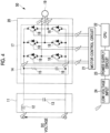
- Fig. 1 is a diagram showing a schematic configuration of an inverter circuit 50 according to one embodiment of the present disclosure.
- the configuration of the inverter circuit 50 shown in Fig. 1 is an example and may be another configuration.
- a direct voltage (DC voltage) is input.
- the direct voltage is input to the filter circuit 11.
- the filter circuit 11 includes a reactor 12 connected in series, for example, as shown in Fig. 1 , and a capacitor (smoothing capacitor) 13 connected in parallel.
- the filter circuit 11 is a type of low-pass filter (LPF).
- the direct voltage is input to the snubber circuit 14.
- the snubber circuit 14 is a circuit that suppresses ringing generated during switching.
- the snubber circuit 14 is, for example, an RC snubber circuit in which an RC unit in which a resistor 15 and a capacitor 16 are directly connected is connected in parallel, as shown in Fig. 1 .
- the switching unit 17 is a three-phase inverter circuit, and is configured by six switching elements 18 as shown in Fig. 1 .
- the switching element 18 is, for example, an IGBT.
- the three-phase alternating current is generated by controlling each IGBT and is output to the motor 19 of the electric compressor.
- Each switching element 18 is controlled by a signal from the motor control circuit 21 to each control terminal.
- the motor control circuit 21 is controlled by the CPU 22.
- the CPU 22 outputs a rotation speed command of the motor 19 to the motor control circuit 21.
- the voltage from the low-voltage input 24 is voltage-regulated by the power supply circuit 23 and the power is supplied to the CPU 22.
- a snubber circuit 14 and a switching unit 17 are formed on a power substrate (inverter substrate) 20.
- the operation recording system 60 records various types of information of the inverter circuit 50 for detecting an abnormality in the inverter circuit 50.
- the operation recording system 60 is mounted on the electric compressor together with, for example, the inverter circuit 50. That is, the electric compressor includes an operation recording system 60 and a motor 19.
- the electric compressor is provided in a vehicle air conditioning system. That is, in the vehicle air conditioning system, the refrigerant is compressed by the electric compressor. Such a vehicle air conditioning system is provided in a vehicle.
- Fig. 2 is a schematic configuration diagram showing an example of a hardware configuration included in an operation recording system 60 according to one embodiment of the present disclosure.
- the operation recording system 60 is a so-called computer, and includes, for example, a central processing unit (CPU) 110, a memory 120, an external interface 140, and a communication interface 150.
- CPU central processing unit
- the above-described components are directly or indirectly connected to each other via a bus, and perform various processes in cooperation with each other.
- the CPU 110 executes various processes, for example, by a program stored in the CPU 110.
- the memory 120 is configured to include, for example, a memory such as an EEPROM. For example, information from various sensors is stored in the memory 120.
- the external interface 140 is an interface for connection to an external device.
- Examples of the external device include an external monitor, a USB memory, and an external HDD.
- an external monitor In an example shown in Fig. 2 , only one external interface is shown. However, a plurality of external interfaces may be provided.
- the communication interface 150 is connected to a network and communicates with other devices to function as an interface for transmission and reception of information.
- the communication interface 150 communicates with other devices in a wired or wireless manner.
- a CAN or a LIN is used.
- wireless communication or the like may be used, and examples thereof include BLUETOOTH (registered trademark), WI-FI, and communication using a dedicated communication protocol.
- wired communication include a wired local area network (LAN).
- the operation recording system 60 includes the abnormality detection unit 64.
- the abnormality detection unit 64 may be omitted.
- information recorded in the recording unit 63 may be taken out and analyzed by an inspector or the like to detect an abnormality.
- the current information is at least one of a current flowing through the switching element 18 in the inverter circuit 50, a current flowing through the capacitor (particularly, the capacitor 13) in the inverter circuit 50, and a surge current generated in the inverter circuit 50.
- the surge voltage is generated in each part shown in Fig. 4 , for example.
- Specific examples include a terminal (a positive electrode terminal and a negative electrode (GND) terminal) to which a direct voltage is supplied, a wire (a positive electrode side and a negative electrode (GND) side) on an output side of the snubber circuit 14 (an input side of the switching unit 17), each three-phase wire on an output side of the switching unit 17, a control wire of each switching element 18 (a wire from the motor control circuit 21 to a control terminal of each switching element 18), and a wire of the low-voltage input 24.
- the surge voltage is detected in the above-described terminal or wire. The same applies to the surge current as to surge voltage.
- the recording processing unit 62 records the operation information and the time information related to the operation information in association with each other.
- the time information is, for example, at least any one of a continuous time, an intermittent time, and a time point.
- the continuous time is a time when the operation information continuously satisfies a predetermined condition.
- the temperature information is a time during which the temperature information is continuously equal to or higher than a predetermined value.
- the intermittent time is a total time when the operation information satisfies a predetermined condition. Specifically, the intermittent time is a time obtained by totaling continuous times in which the operation information satisfies the predetermined condition within a predetermined period.
- the acquisition target of the temperature information for example, the temperature of the switching element 18
- the time during which the temperature exceeds a certain threshold value or the time point when the temperature exceeds a certain threshold value are recorded.
- the amount of data to be recorded can be reduced.
- a value obtained by time-integrating the value of the temperature may be recorded.
- the acquisition target of the temperature information targeting a component that generates heat like the switching element 18 or a component set in advance as a target because of being sensitive to heat is effective for abnormality detection.
- the heat-generating component is in a high-temperature state for a long time, it can be determined that abnormal heat generation has occurred, and when the temperature of the heat-sensitive component is high for a long time, it can be determined that the component is abnormal.
- notification means for notifying an inspector or the like that the operation information has been recorded may be further included.
- the operation information may be indirectly notified to an inspector or the like through the abnormality detection of another device connected to the compressor.
- the operation may be simply to regularly perform an inspection.
- the notification means may not need to be provided, and the operation information and the time information may be "associated" with each other by other methods within a scope not departing from the scope of the invention.
- An operation recording system (60) is an operation recording system applied to an electric compressor of a vehicle air conditioning system including an inverter circuit (50), the operation recording system includes an acquisition unit (61) that acquires, as abnormality reference information, at least one of temperature information at a predetermined position in the inverter circuit, voltage information at the predetermined position in the inverter circuit, and current information at the predetermined position in the inverter circuit; and a recording processing unit (62) that records the abnormality reference information and time information capable of being associated with the abnormality reference information in a predetermined recording unit (63).
- the operation recording system it is possible to efficiently detect or predict an abnormality by recording the time information in association with at least one of the temperature information, the voltage information, and the current information as the abnormality reference information in the electric compressor of the vehicle air conditioning system. That is, for example, it is possible to take out the information recorded at the time of the regular inspection and perform a detailed inspection.
- a second aspect of the present disclosure provides the operation recording system according to the first aspect, in which the temperature information may be at least one of a temperature of a switching element (18) in the inverter circuit, a temperature of a capacitor in the inverter circuit, and a temperature of a CPU in the inverter circuit.
- the operation recording system of the present disclosure by using at least one of a temperature of a switching element, a temperature of a capacitor, and a temperature of a CPU as temperature information, it is possible to effectively use the information as the abnormality reference information in an electric compressor of a vehicle air conditioning system.
- a third aspect of the present disclosure provides the operation recording system according to the first aspect or the second aspect, in which the voltage information may be at least one of a voltage of the switching element in the inverter circuit, a voltage of the capacitor in the inverter circuit, and a surge voltage generated in the inverter circuit.
- a fourth aspect of the present disclosure provides the operation recording system according to any one of the first aspect to the third aspect, in which the current information may be at least one of a current flowing through the switching element in the inverter circuit, a current flowing through the capacitor in the inverter circuit, and a surge current generated in the inverter circuit.
- the operation recording system of the present disclosure by using at least one of the current flowing through the switching element, the current flowing through the capacitor, and the surge current as the current information, it is possible to effectively use the information as the abnormality reference information in an electric compressor of a vehicle air conditioning system.
- a fifth aspect of the present disclosure provides the operation recording system according to any one of the first aspect to the fourth aspect, in which the recording unit may be a memory built in the electric compressor in advance or a memory provided in a device different from the electric compressor.
- the recording unit may be a memory built in the electric compressor, or may be a memory provided in a device different from the electric compressor.
- a sixth aspect of the present disclosure provides the operation recording system according to any one of the first aspect to the fifth aspect, in which the time information may be at least one of a continuous time that is a time when the abnormality reference information continuously satisfies a predetermined condition, an intermittent time that is a total time when the abnormality reference information satisfies the predetermined condition, and a detection time of the abnormality reference information.
- the operation recording system of the present disclosure it is possible to effectively perform the abnormality detection by using at least one of the continuous time, the intermittent time, and the detection time as the time information.
- a ninth aspect of the present disclosure provides the operation recording system according to the seventh aspect, in which the abnormality detection unit may perform abnormality detection in a case where, when a voltage value indicated by the voltage information is equal to or higher than a threshold value, a total time is equal to or higher than a threshold value.
- a tenth aspect of the present disclosure provides the operation recording system according to the seventh aspect, in which the abnormality detection unit may perform abnormality detection in a case where, when a current value indicated by the current information is equal to or higher than a threshold value, a total time is equal to or higher than a threshold value.
- An electric compressor according to an eleventh aspect of the present disclosure includes the operation recording system according to any one of the first aspect to the tenth aspect, and a motor (19).
- a vehicle air conditioning system includes the electric compressor according to the eleventh aspect.
- a vehicle according to a thirteenth aspect of the present disclosure includes the vehicle air conditioning system according to the twelfth aspect.
- An operation recording method is an operation recording method applied to an electric compressor of a vehicle air conditioning system including an inverter circuit, the method includes an acquiring step of acquiring, as abnormality reference information, at least one of temperature information at a predetermined position in the inverter circuit, voltage information at the predetermined position in the inverter circuit, and current information at the predetermined position in the inverter circuit; and a recording processing step of recording the abnormality reference information and time information capable of being associated with the abnormality reference information in a predetermined recording unit.
Landscapes
- Engineering & Computer Science (AREA)
- Mechanical Engineering (AREA)
- General Engineering & Computer Science (AREA)
- Power Engineering (AREA)
- Physics & Mathematics (AREA)
- Thermal Sciences (AREA)
- Computer Hardware Design (AREA)
- Inverter Devices (AREA)
- Air-Conditioning For Vehicles (AREA)
- Control Of Positive-Displacement Pumps (AREA)
Abstract
Description
- The present disclosure relates to an operation recording system, a vehicle, an operation recording method, and an operation recording program.
- A compressor is used for an air conditioner to compress a refrigerant. In the compressor, an operation state may be detected and used as an item for controlling an operation of the compressor (PTL 1 and PTL 2).
-
- [PTL 1]
Japanese Unexamined Patent Application Publication No. 2017-161195 - [PTL 2]
Japanese Unexamined Patent Application Publication No. 2018-74632 - For example, regarding on an abnormality of the compressor, a simple abnormality detection such as determining that an abnormality has occurred when a voltage is lowered to a value equal to or less than a threshold value may be performed. However, although the comparison between one item (for example, voltage) and the threshold value can detect abnormality in the real-time, it is difficult to perform a detailed analysis of the abnormality detection. A memory mounted in a compressor (particularly, a vehicle air conditioner) has a small capacity and has not been used to store, for example, an operation state with a sufficient amount of data. As described above, there is a possibility that the accuracy of the abnormality detection of the compressor can be further improved.
- The present disclosure has been made in view of such circumstances, and an object thereof is to provide an operation recording system, a vehicle, an operation recording method, and an operation recording program, which can perform an abnormality analysis of a compressor with high accuracy.
- An operation recording system according to an aspect in some embodiments of the present disclosure is an operation recording system applied to an electric compressor of a vehicle air conditioning system including an inverter circuit, the operation recording system includes an acquisition unit that acquires, as abnormality reference information, at least one of temperature information at a predetermined position in the inverter circuit, voltage information at the predetermined position in the inverter circuit, and current information at the predetermined position in the inverter circuit; and a recording processing unit that records the abnormality reference information and time information capable of being associated with the abnormality reference information in a predetermined recording unit.
- An operation recording method according to an aspect in some embodiments of the present disclosure is an operation recording method applied to an electric compressor of a vehicle air conditioning system including an inverter circuit, the method includes an acquiring step of acquiring, as abnormality reference information, at least one of temperature information at a predetermined position in the inverter circuit, voltage information at the predetermined position in the inverter circuit, and current information at the predetermined position in the inverter circuit; and a recording processing step of recording the abnormality reference information and time information capable of being associated with the abnormality reference information in a predetermined recording unit.
- According to the present disclosure, there is an effect that it is possible to perform highly accurate abnormality analysis of a compressor.
-
-
Fig. 1 is a diagram showing a schematic configuration of an inverter circuit according to one embodiment of the present disclosure. -
Fig. 2 is a schematic configuration diagram showing an example of a hardware configuration included in an operation recording system according to one embodiment of the present disclosure. -
Fig. 3 is a functional block diagram showing functions included in the operation recording system according to one embodiment of the present disclosure. -
Fig. 4 is a diagram showing an example of generation of a surge current according to one embodiment of the present disclosure. -
Fig. 5 is a flowchart showing an example of a procedure to deal with the process according to one embodiment of the present disclosure. - Hereinafter, an operation recording system, a vehicle, an operation recording method, and an operation recording program according to one embodiment of the present disclosure will be described with reference to the drawings.
-
Fig. 1 is a diagram showing a schematic configuration of aninverter circuit 50 according to one embodiment of the present disclosure. The configuration of theinverter circuit 50 shown inFig. 1 is an example and may be another configuration. - In the
inverter circuit 50, a direct voltage (DC voltage) is input. For example, as shown inFig. 1 , the direct voltage is input to thefilter circuit 11. Thefilter circuit 11 includes areactor 12 connected in series, for example, as shown inFig. 1 , and a capacitor (smoothing capacitor) 13 connected in parallel. Thefilter circuit 11 is a type of low-pass filter (LPF). - The direct voltage is input to the
snubber circuit 14. Thesnubber circuit 14 is a circuit that suppresses ringing generated during switching. Thesnubber circuit 14 is, for example, an RC snubber circuit in which an RC unit in which aresistor 15 and acapacitor 16 are directly connected is connected in parallel, as shown inFig. 1 . - Then, the direct voltage is connected to the
switching unit 17 via thesnubber circuit 14. Theswitching unit 17 is a three-phase inverter circuit, and is configured by sixswitching elements 18 as shown inFig. 1 . Theswitching element 18 is, for example, an IGBT. The three-phase alternating current is generated by controlling each IGBT and is output to themotor 19 of the electric compressor. - Each
switching element 18 is controlled by a signal from themotor control circuit 21 to each control terminal. Themotor control circuit 21 is controlled by theCPU 22. For example, theCPU 22 outputs a rotation speed command of themotor 19 to themotor control circuit 21. The voltage from the low-voltage input 24 is voltage-regulated by thepower supply circuit 23 and the power is supplied to theCPU 22. - As shown in
Fig. 1 , for example, asnubber circuit 14 and aswitching unit 17 are formed on a power substrate (inverter substrate) 20. - The
operation recording system 60 records various types of information of theinverter circuit 50 for detecting an abnormality in theinverter circuit 50. - The
operation recording system 60 is mounted on the electric compressor together with, for example, theinverter circuit 50. That is, the electric compressor includes anoperation recording system 60 and amotor 19. The electric compressor is provided in a vehicle air conditioning system. That is, in the vehicle air conditioning system, the refrigerant is compressed by the electric compressor. Such a vehicle air conditioning system is provided in a vehicle. -
Fig. 2 is a schematic configuration diagram showing an example of a hardware configuration included in anoperation recording system 60 according to one embodiment of the present disclosure. As shown inFig. 2 , theoperation recording system 60 is a so-called computer, and includes, for example, a central processing unit (CPU) 110, amemory 120, anexternal interface 140, and acommunication interface 150. The above-described components are directly or indirectly connected to each other via a bus, and perform various processes in cooperation with each other. - The
CPU 110 executes various processes, for example, by a program stored in theCPU 110. - The
memory 120 is configured to include, for example, a memory such as an EEPROM. For example, information from various sensors is stored in thememory 120. - The
external interface 140 is an interface for connection to an external device. Examples of the external device include an external monitor, a USB memory, and an external HDD. In an example shown inFig. 2 , only one external interface is shown. However, a plurality of external interfaces may be provided. - The
communication interface 150 is connected to a network and communicates with other devices to function as an interface for transmission and reception of information. - For example, the
communication interface 150 communicates with other devices in a wired or wireless manner. As the vehicle, a CAN or a LIN is used. In addition, wireless communication or the like may be used, and examples thereof include BLUETOOTH (registered trademark), WI-FI, and communication using a dedicated communication protocol. Examples of wired communication include a wired local area network (LAN). - For example, an
input unit 160 and adisplay unit 170 may be provided. Theinput unit 160 is, for example, a user interface for issuing an instruction such as a keyboard, a mouse, and a touch pad. Thedisplay unit 170 is, for example, a liquid-crystal display, an organic electroluminescence (EL) display, or the like. Thedisplay unit 170 may be a touch panel display overlaid with a touch panel. -
Fig. 3 is a functional block diagram showing functions included in theoperation recording system 60. As shown inFig. 3 , theoperation recording system 60 includes anacquisition unit 61, arecording processing unit 62, arecording unit 63, and anabnormality detection unit 64. - The
operation recording system 60 is mounted on, for example, the electric compressor, but the functions of the respective units are not limited to being mounted on the electric compressor. For example, theacquisition unit 61 and therecording processing unit 62 may be mounted on the electric compressor, and therecording unit 63 may be provided in a device (for example, a server) different from the electric compressor, or theabnormality detection unit 64 may be provided in a device (for example, a server) different from the electric compressor, and the location of each function may be centralized in one device or may be distributed to a plurality of devices. - In the present embodiment, the
operation recording system 60 includes theabnormality detection unit 64. However, theabnormality detection unit 64 may be omitted. In this case, for example, information recorded in therecording unit 63 may be taken out and analyzed by an inspector or the like to detect an abnormality. - The
acquisition unit 61 acquires, as operation information (abnormality reference information), at least one of the temperature information at the predetermined position in theinverter circuit 50, the voltage information at the predetermined position in theinverter circuit 50, and the current information at the predetermined position in theinverter circuit 50. The operation information (abnormality reference information) is information that is used as a reference for abnormality detection. That is, the operation information is the operation information related to the abnormality, and specifically, is the temperature information, the current information, and the voltage information. Information other than the above may also be used as the operation information. For example, the rotation speed of the compressor may be used. - The temperature information is at least one of a temperature of the switching element (IGBT) 18 in the
inverter circuit 50, a temperature of the capacitor (particularly, the capacitor 13) in theinverter circuit 50, and a temperature of theCPU 22 and other components (components set in advance as targets) to be monitored thermally in theinverter circuit 50. - The voltage information is at least one of a voltage of the switching
element 18 in theinverter circuit 50, a voltage of the capacitor (particularly, the capacitor 13) in theinverter circuit 50, and a surge voltage generated in theinverter circuit 50. - The current information is at least one of a current flowing through the switching
element 18 in theinverter circuit 50, a current flowing through the capacitor (particularly, the capacitor 13) in theinverter circuit 50, and a surge current generated in theinverter circuit 50. - The surge voltage is generated in each part shown in
Fig. 4 , for example. Specific examples include a terminal (a positive electrode terminal and a negative electrode (GND) terminal) to which a direct voltage is supplied, a wire (a positive electrode side and a negative electrode (GND) side) on an output side of the snubber circuit 14 (an input side of the switching unit 17), each three-phase wire on an output side of the switchingunit 17, a control wire of each switching element 18 (a wire from themotor control circuit 21 to a control terminal of each switching element 18), and a wire of the low-voltage input 24. For example, the surge voltage is detected in the above-described terminal or wire. The same applies to the surge current as to surge voltage. - The
recording unit 63 is a unit capable of recording information. Therecording unit 63 is, for example, a memory. Therecording unit 63 is, for example, a memory that is built in advance in the electric compressor. However, therecording unit 63 is not limited to being built in the electric compressor, and may be provided in a device different from the electric compressor, for example. - The
recording processing unit 62 records the operation information and the time information in association with each other in thepredetermined recording unit 63. That is, therecording processing unit 62 performs recording processing of the operation information associated with the time information in therecording unit 63. - Specifically, the
recording processing unit 62 records the operation information and the time information related to the operation information in association with each other. The time information is, for example, at least any one of a continuous time, an intermittent time, and a time point. The continuous time is a time when the operation information continuously satisfies a predetermined condition. For example, the temperature information is a time during which the temperature information is continuously equal to or higher than a predetermined value. The intermittent time is a total time when the operation information satisfies a predetermined condition. Specifically, the intermittent time is a time obtained by totaling continuous times in which the operation information satisfies the predetermined condition within a predetermined period. For example, in a case where the time during which the temperature information is continuously equal to or higher than the predetermined value within the predetermined period is defined as T1 and T2, the intermittent time is T1 + T2. The time point is a detection time of the operation information. For example, a value detected as temperature information and the time point thereof are associated with each other. An operation cumulative time may be used as the time information. The operation cumulative time (compressor operation time) is, for example, a cumulative time from a factory shipment. - In a case of associating the temperature information with the time information, for example, the acquisition target of the temperature information (for example, the temperature of the switching element 18) and the time during which the temperature exceeds a certain threshold value or the time point when the temperature exceeds a certain threshold value are recorded. In such a case, the amount of data to be recorded can be reduced. A value obtained by time-integrating the value of the temperature may be recorded. As the acquisition target of the temperature information, targeting a component that generates heat like the switching
element 18 or a component set in advance as a target because of being sensitive to heat is effective for abnormality detection. When the heat-generating component is in a high-temperature state for a long time, it can be determined that abnormal heat generation has occurred, and when the temperature of the heat-sensitive component is high for a long time, it can be determined that the component is abnormal. - In a case of associating the voltage information with the time information, for example, the acquisition target of the voltage information (for example, the voltage of the switching element 18) and the time during which the voltage exceeds a certain threshold value or the time point when the voltage exceeds a certain threshold value are recorded. In such a case, the amount of data to be recorded can be reduced. A value obtained by time-integrating the value of the voltage may be recorded.
- In a case of associating the current information with the time information, for example, the acquisition target of the current information (for example, the current flowing through the switching element 18) and the time during which the current exceeds a certain threshold value or the time point when the current exceeds a certain threshold value are recorded. In such a case, the amount of data to be recorded can be reduced. A value obtained by time-integrating the value of the current may be recorded.
- In this way, the
recording processing unit 62 records the operation information and the time information in association with each other. Therefore, it is possible to perform the abnormality detection with high accuracy by referring to the record information. The record may be made in association with condition, surrounding information, vehicle information, and compressor information. For example, the records may be recorded in association with vehicle speed, whether charging is required or not, ambient temperature, battery voltage, compressor rotation speed, highpressure pressure, the low-pressure pressure, or the like. - The
abnormality detection unit 64 performs abnormality detection based on the information recorded in therecording unit 63. Specifically, theabnormality detection unit 64 takes out the information of therecording unit 63 and performs abnormality detection on theinverter circuit 50. As the abnormality detection, it may be detected that the abnormality has occurred, or it may be detected that there is a high possibility of an abnormality occurring (precursor to abnormality) before the abnormality actually occurs (abnormality prediction). - For example, in a case where the acquisition target of the temperature information (for example, the temperature of the switching element 18) and the time during which the temperature exceeds a certain threshold value or the time point when the temperature exceeds a certain threshold value are recorded, when the total time in which the temperature indicated by the temperature information is equal to or higher than the threshold value is equal to or higher than the threshold value, it is assumed that the high-temperature state continues for a long time, and thus the abnormality detection is performed. In a case of recording a value obtained by time-integrating the value of the temperature, the abnormality detection may be performed in a case where the integrated value is equal to or higher than a threshold value.
- For example, in a case where the acquisition target of the voltage information (for example, a voltage of the switching element 18) and the time during which the voltage exceeds a certain threshold value or the time point when the voltage exceeds a certain threshold value are recorded, when the total time in which the voltage value indicated by the voltage information is equal to or higher than the threshold value is equal to or higher than the threshold value, it is assumed that the high-voltage state continues for a long time, and thus the abnormality detection is performed. In a case of recording a value obtained by time-integrating the value of the voltage, the abnormality detection may be performed in a case where the integrated value is equal to or higher than a threshold value.
- For example, in a case where the acquisition target of the current information (for example, the current flowing through the switching element 18) and the time during which the current exceeds a certain threshold value or the time point when the current exceeds a certain threshold value are recorded, when the total time in which the current value indicated by the current information is equal to or higher than the threshold value is equal to or higher than the threshold value, it is assumed that the high-current state continues for a long time, and thus the abnormality detection is performed. In a case of recording a value obtained by time-integrating the value of the current, the abnormality detection may be performed in a case where the integrated value is equal to or higher than a threshold value.
- The abnormality detection unit64 performs the detection as described above to detect the abnormality in the
inverter circuit 50. In the abnormality detection, an abnormality degree or a possibility of the abnormality may be output, or a flag may be output in a case where the abnormality degree or the possibility of the abnormality is equal to or higher than a predetermined value. - Next, an example of a process by the above-described
operation recording system 60 will be described with reference toFig. 5. Fig. 5 is a flowchart showing an example of procedure to deal with the process according to the present embodiment. The flow shown inFig. 5 is repeatedly executed, for example, in a predetermined control cycle. - First, operation information is acquired (S101). Then, the operation information and the time information are associated with each other and recorded in the recording unit 63 (S102).
- Then, the abnormality detection is performed based on the information recorded in the recording unit 63 (S103). The abnormality detection in S103 may be omitted. In this case, for example, the recorded information may be taken out and analyzed by an analyst or the like.
- As described above, according to the operation recording system, the vehicle, the operation recording method, and the operation recording program according to the present embodiment, it is possible to efficiently detect or predict an abnormality by recording the time information in association with at least one of the temperature information, the voltage information, and the current information as the abnormality reference information in the electric compressor of the vehicle air conditioning system. That is, for example, it is possible to take out the information recorded at the time of the regular inspection and perform a detailed inspection.
- The present disclosure is not limited to only the embodiments described above, and various modifications can be made within a scope which does not depart from the concept of the invention.
- In the above-described embodiment, a case where the operation information and the time information are recorded in association with each other has been described as an example, but the present disclosure is not limited to this example. For example, the
recording processing unit 62 may record the abnormality reference information and the time information capable of being associated with the abnormality reference information in apredetermined recording unit 63. More specifically, therecording processing unit 62 may record the abnormality reference information and the time information related to the abnormality reference information in thepredetermined recording unit 63. - For example, in a case where an inspector or the like confirms an output signal of various sensors, an abnormal noise, or an abnormality such as a defect detected by various sensors by some method, information (an example of "time information") such as the operation time of the compressor at the time of confirmation may be collated. In this case, at the time of recording the operation information ("abnormality reference information"), the operation information and the time information are not associated with each other, and the cumulative operation time from the factory shipment is simply counted. Then, when the operation information is recorded, the cumulative operation time at the time of recording may be acquired, and it may be estimated that the time point when the operation information is recorded is around the cumulative operation time.
- In this example, notification means for notifying an inspector or the like that the operation information has been recorded may be further included. The operation information may be indirectly notified to an inspector or the like through the abnormality detection of another device connected to the compressor. The operation may be simply to regularly perform an inspection. The notification means may not need to be provided, and the operation information and the time information may be "associated" with each other by other methods within a scope not departing from the scope of the invention.
- The operation recording system, the vehicle, the operation recording method, and the operation recording program described in each of the above-described embodiments are understood as follows, for example.
- An operation recording system (60) according to a first aspect of the present disclosure is an operation recording system applied to an electric compressor of a vehicle air conditioning system including an inverter circuit (50), the operation recording system includes an acquisition unit (61) that acquires, as abnormality reference information, at least one of temperature information at a predetermined position in the inverter circuit, voltage information at the predetermined position in the inverter circuit, and current information at the predetermined position in the inverter circuit; and a recording processing unit (62) that records the abnormality reference information and time information capable of being associated with the abnormality reference information in a predetermined recording unit (63).
- The operation recording system according to the present disclosure, it is possible to efficiently detect or predict an abnormality by recording the time information in association with at least one of the temperature information, the voltage information, and the current information as the abnormality reference information in the electric compressor of the vehicle air conditioning system. That is, for example, it is possible to take out the information recorded at the time of the regular inspection and perform a detailed inspection.
- A second aspect of the present disclosure provides the operation recording system according to the first aspect, in which the temperature information may be at least one of a temperature of a switching element (18) in the inverter circuit, a temperature of a capacitor in the inverter circuit, and a temperature of a CPU in the inverter circuit.
- According to the operation recording system of the present disclosure, by using at least one of a temperature of a switching element, a temperature of a capacitor, and a temperature of a CPU as temperature information, it is possible to effectively use the information as the abnormality reference information in an electric compressor of a vehicle air conditioning system.
- A third aspect of the present disclosure provides the operation recording system according to the first aspect or the second aspect, in which the voltage information may be at least one of a voltage of the switching element in the inverter circuit, a voltage of the capacitor in the inverter circuit, and a surge voltage generated in the inverter circuit.
- According to the operation recording system according to the present disclosure, it is possible to effectively use the information as the abnormality reference information in the electric compressor of a vehicle air conditioning system.
- A fourth aspect of the present disclosure provides the operation recording system according to any one of the first aspect to the third aspect, in which the current information may be at least one of a current flowing through the switching element in the inverter circuit, a current flowing through the capacitor in the inverter circuit, and a surge current generated in the inverter circuit.
- According to the operation recording system of the present disclosure, by using at least one of the current flowing through the switching element, the current flowing through the capacitor, and the surge current as the current information, it is possible to effectively use the information as the abnormality reference information in an electric compressor of a vehicle air conditioning system.
- A fifth aspect of the present disclosure provides the operation recording system according to any one of the first aspect to the fourth aspect, in which the recording unit may be a memory built in the electric compressor in advance or a memory provided in a device different from the electric compressor.
- According to the operation recording system of the present disclosure, the recording unit may be a memory built in the electric compressor, or may be a memory provided in a device different from the electric compressor.
- A sixth aspect of the present disclosure provides the operation recording system according to any one of the first aspect to the fifth aspect, in which the time information may be at least one of a continuous time that is a time when the abnormality reference information continuously satisfies a predetermined condition, an intermittent time that is a total time when the abnormality reference information satisfies the predetermined condition, and a detection time of the abnormality reference information.
- According to the operation recording system of the present disclosure, it is possible to effectively perform the abnormality detection by using at least one of the continuous time, the intermittent time, and the detection time as the time information.
- A seventh aspect of the present disclosure provides the operation recording system according to any one of the first aspect to the sixth aspect, which further includes an abnormality detection unit (64) that performs abnormality detection based on information recorded in the recording unit.
- According to the operation recording system according to the present disclosure, it is possible to perform more accurate abnormality detection based on the information recorded in the recording unit. As the abnormality detection, it may be detected that the abnormality has occurred, or it may be detected that there is a high possibility of an abnormality occurring (precursor to abnormality) before the abnormality actually occurs.
- An eighth aspect of the present disclosure provides the operation recording system according to the seventh aspect, in which the abnormality detection unit may perform abnormality detection in a case where, when a temperature indicated by the temperature information is equal to or higher than a threshold value, a total time is equal to or higher than a threshold value.
- According to the operation recording system according to the present disclosure, it is assumed that the high-temperature state continues for a long time, and thus it is possible to detect an abnormality.
- A ninth aspect of the present disclosure provides the operation recording system according to the seventh aspect, in which the abnormality detection unit may perform abnormality detection in a case where, when a voltage value indicated by the voltage information is equal to or higher than a threshold value, a total time is equal to or higher than a threshold value.
- According to the operation recording system according to the present disclosure, it is assumed that the high-voltage state continues for a long time, and thus it is possible to detect an abnormality.
- A tenth aspect of the present disclosure provides the operation recording system according to the seventh aspect, in which the abnormality detection unit may perform abnormality detection in a case where, when a current value indicated by the current information is equal to or higher than a threshold value, a total time is equal to or higher than a threshold value.
- According to the operation recording system according to the present disclosure, it is assumed that the high-current state continues for a long time, and thus it is possible to detect an abnormality.
- An electric compressor according to an eleventh aspect of the present disclosure includes the operation recording system according to any one of the first aspect to the tenth aspect, and a motor (19).
- A vehicle air conditioning system according to a twelfth aspect of the present disclosure includes the electric compressor according to the eleventh aspect.
- A vehicle according to a thirteenth aspect of the present disclosure includes the vehicle air conditioning system according to the twelfth aspect.
- An operation recording method according to a fourteenth aspect of the present disclosure is an operation recording method applied to an electric compressor of a vehicle air conditioning system including an inverter circuit, the method includes an acquiring step of acquiring, as abnormality reference information, at least one of temperature information at a predetermined position in the inverter circuit, voltage information at the predetermined position in the inverter circuit, and current information at the predetermined position in the inverter circuit; and a recording processing step of recording the abnormality reference information and time information capable of being associated with the abnormality reference information in a predetermined recording unit.
-
- 11: filter circuit
- 12: reactor
- 13: capacitor
- 14: snubber circuit
- 15: resistor
- 16: capacitor
- 17: switching unit
- 18: switching element
- 19: motor
- 21: motor control circuit
- 22: CPU
- 23: power supply circuit
- 24: low-voltage input
- 50: inverter circuit
- 60: operation recording system
- 61: acquisition unit
- 62: recording processing unit
- 63: recording unit
- 64: abnormality detection unit
- 110: CPU
- 120: memory
- 140: external interface
- 150: communication interface
- 160: input unit
- 170: display unit
Claims (14)
- An operation recording system applied to an electric compressor of a vehicle air conditioning system including an inverter circuit, the operation recording system comprising:an acquisition unit that acquires, as abnormality reference information, at least one of temperature information at a predetermined position in the inverter circuit, voltage information at the predetermined position in the inverter circuit, and current information at the predetermined position in the inverter circuit; anda recording processing unit that records the abnormality reference information and time information capable of being associated with the abnormality reference information in a predetermined recording unit.
- The operation recording system according to Claim 1, wherein
the temperature information is at least one of a temperature of a switching element in the inverter circuit, a temperature of a capacitor in the inverter circuit, and a temperature of a CPU in the inverter circuit. - The operation recording system according to Claim 1, wherein
the voltage information is at least one of a voltage of a switching element in the inverter circuit, a voltage of a capacitor in the inverter circuit, and a surge voltage generated in the inverter circuit. - The operation recording system according to Claim 1, wherein
the current information is at least one of a current flowing through a switching element in the inverter circuit, a current flowing through a capacitor in the inverter circuit, and a surge current generated in the inverter circuit. - The operation recording system according to Claim 1, wherein
the recording unit is a memory built in the electric compressor in advance or a memory provided in a device different from the electric compressor. - The operation recording system according to Claim 1, wherein
the time information is at least one of a continuous time that is a time when the abnormality reference information continuously satisfies a predetermined condition, an intermittent time that is a total time when the abnormality reference information satisfies the predetermined condition, and a detection time of the abnormality reference information. - The operation recording system according to Claim 1, further comprising:
an abnormality detection unit that performs abnormality detection based on information recorded in the recording unit. - The operation recording system according to Claim 7, wherein
the abnormality detection unit performs abnormality detection in a case where, when a temperature indicated by the temperature information is equal to or higher than a threshold value, a total time is equal to or higher than a threshold value. - The operation recording system according to Claim 7, wherein
the abnormality detection unit performs abnormality detection in a case where, when a voltage value indicated by the voltage information is equal to or higher than a threshold value, a total time is equal to or higher than a threshold value. - The operation recording system according to Claim 7, wherein
the abnormality detection unit performs abnormality detection in a case where, when a current value indicated by the current information is equal to or higher than a threshold value, a total time is equal to or higher than a threshold value. - An electric compressor comprising:the operation recording system according to Claim 1; anda motor.
- A vehicle air conditioning system comprising:
the electric compressor according to Claim 11. - A vehicle comprising:
the vehicle air conditioning system according to Claim 12. - An operation recording method applied to an electric compressor of a vehicle air conditioning system including an inverter circuit, the method comprising:an acquiring step of acquiring, as abnormality reference information, at least one of temperature information at a predetermined position in the inverter circuit, voltage information at the predetermined position in the inverter circuit, and current information at the predetermined position in the inverter circuit; anda recording processing step of recording the abnormality reference information and time information capable of being associated with the abnormality reference information in a predetermined recording unit.
Applications Claiming Priority (2)
| Application Number | Priority Date | Filing Date | Title |
|---|---|---|---|
| JP2022084608A JP2023172653A (en) | 2022-05-24 | 2022-05-24 | Operation recording system, vehicle, operation recording method, and operation recording program |
| PCT/JP2023/005334 WO2023228489A1 (en) | 2022-05-24 | 2023-02-15 | Operation recording system, vehicle, operation recording method and operation recording program |
Publications (2)
| Publication Number | Publication Date |
|---|---|
| EP4513036A1 true EP4513036A1 (en) | 2025-02-26 |
| EP4513036A4 EP4513036A4 (en) | 2025-04-23 |
Family
ID=88918958
Family Applications (1)
| Application Number | Title | Priority Date | Filing Date |
|---|---|---|---|
| EP23811370.8A Withdrawn EP4513036A4 (en) | 2022-05-24 | 2023-02-15 | Operation recording system, vehicle, operation recording method and operation recording program |
Country Status (5)
| Country | Link |
|---|---|
| US (1) | US20250317084A1 (en) |
| EP (1) | EP4513036A4 (en) |
| JP (1) | JP2023172653A (en) |
| CN (1) | CN119278316A (en) |
| WO (1) | WO2023228489A1 (en) |
Family Cites Families (13)
| Publication number | Priority date | Publication date | Assignee | Title |
|---|---|---|---|---|
| JP3316263B2 (en) * | 1993-07-09 | 2002-08-19 | 三洋電機株式会社 | Air conditioner |
| JP2005315092A (en) * | 2004-04-27 | 2005-11-10 | Matsushita Electric Ind Co Ltd | Compressor control device |
| WO2008108020A1 (en) * | 2007-03-06 | 2008-09-12 | Mitsubishi Heavy Industries, Ltd. | Inverter system for vehicle-mounted air conditioner |
| JP5473212B2 (en) * | 2007-12-06 | 2014-04-16 | 三菱重工業株式会社 | Inverter system for in-vehicle air conditioner |
| US8796982B2 (en) * | 2011-12-15 | 2014-08-05 | Eaton Corporation | System and method for detecting phase loss and diagnosing DC link capacitor health in an adjustable speed drive |
| JP6012506B2 (en) * | 2013-02-22 | 2016-10-25 | 三菱重工オートモーティブサーマルシステムズ株式会社 | Cooling fan motor / inverter system for vehicle, control method and program thereof |
| JP6613698B2 (en) * | 2015-08-07 | 2019-12-04 | マックス株式会社 | Air compressor |
| JP2017161195A (en) | 2016-03-11 | 2017-09-14 | 株式会社デンソー | Refrigeration cycle device |
| JP6840989B2 (en) | 2016-10-24 | 2021-03-10 | 株式会社ジェイテクト | Electric oil pump control device and electric oil pump unit |
| CN111225847B (en) * | 2017-10-23 | 2022-02-08 | 三菱电机株式会社 | Recording device for railway vehicle, air conditioning device for railway vehicle, and recording method for railway vehicle |
| US11480356B2 (en) * | 2017-12-11 | 2022-10-25 | Johnson Controls Tyco IP Holdings LLP | Thermostat with startup temperature estimation |
| JP7391605B2 (en) * | 2019-10-24 | 2023-12-05 | 三菱重工サーマルシステムズ株式会社 | Control device, electric compressor, ripple voltage abnormality cause determination method and program |
| JP7285969B2 (en) * | 2020-01-22 | 2023-06-02 | 三菱電機株式会社 | Motor controller and air conditioner |
-
2022
- 2022-05-24 JP JP2022084608A patent/JP2023172653A/en not_active Withdrawn
-
2023
- 2023-02-15 CN CN202380040148.5A patent/CN119278316A/en not_active Withdrawn
- 2023-02-15 US US18/865,592 patent/US20250317084A1/en active Pending
- 2023-02-15 EP EP23811370.8A patent/EP4513036A4/en not_active Withdrawn
- 2023-02-15 WO PCT/JP2023/005334 patent/WO2023228489A1/en not_active Ceased
Also Published As
| Publication number | Publication date |
|---|---|
| CN119278316A (en) | 2025-01-07 |
| US20250317084A1 (en) | 2025-10-09 |
| EP4513036A4 (en) | 2025-04-23 |
| JP2023172653A (en) | 2023-12-06 |
| WO2023228489A1 (en) | 2023-11-30 |
Similar Documents
| Publication | Publication Date | Title |
|---|---|---|
| US8639474B2 (en) | Microcontroller-based diagnostic module | |
| US8898525B2 (en) | Method and system for use in condition monitoring | |
| CA3009773A1 (en) | Prognostic and health monitoring systems for light fixtures | |
| EP2677479A1 (en) | Energy consumption monitoring system, method, and computer program | |
| US10401401B2 (en) | System and methods thereof for monitoring of energy consumption cycles | |
| EP2787630B1 (en) | Detecting faults in motors and drives | |
| JP2019096289A (en) | Abnormality detector, abnormality detection method, abnormality detection program, and abnormality detection system | |
| JPWO2018154845A1 (en) | Management device, management method, and program | |
| CN109699196B (en) | Power conversion device and power conversion device system | |
| CN104865895A (en) | Controller Having Cpu Abnormality Detection Function | |
| US20250317084A1 (en) | Operation recording system, vehicle, operation recording method and operation recording program | |
| CN110262362B (en) | An AGV working temperature monitoring method, system and device | |
| CN112346552A (en) | Power supply monitoring method and device, computer equipment and storage medium | |
| CN114326993B (en) | Chip temperature control method, device and system of target equipment | |
| EP2725336B1 (en) | Apparatus and Method To Detect Damage of a Component of a System | |
| EP4113236A1 (en) | Run-time reliability reporting for electrical hardware systems | |
| CN105656327A (en) | State monitoring method, power adapter and electronic equipment | |
| JP2018077634A (en) | Plant equipment deterioration diagnosis device | |
| CN114838848B (en) | Temperature sampling control method, device, equipment and storage medium | |
| CN105468495B (en) | Complicated formula can procedure logical control system device | |
| US12163848B2 (en) | Method and apparatus for identifying probe abnormity, storage medium, and electronic device | |
| CN115987178A (en) | Multi-point temperature protection method, motor control device and storage medium | |
| US11720435B2 (en) | Electronic device and fault diagnosis method of electronic device | |
| KR102781009B1 (en) | Smart led display device capable of active failure prediction and response using failure prediction data | |
| CN104122973A (en) | Monitoring device |
Legal Events
| Date | Code | Title | Description |
|---|---|---|---|
| STAA | Information on the status of an ep patent application or granted ep patent |
Free format text: STATUS: THE INTERNATIONAL PUBLICATION HAS BEEN MADE |
|
| PUAI | Public reference made under article 153(3) epc to a published international application that has entered the european phase |
Free format text: ORIGINAL CODE: 0009012 |
|
| STAA | Information on the status of an ep patent application or granted ep patent |
Free format text: STATUS: REQUEST FOR EXAMINATION WAS MADE |
|
| 17P | Request for examination filed |
Effective date: 20241121 |
|
| AK | Designated contracting states |
Kind code of ref document: A1 Designated state(s): AL AT BE BG CH CY CZ DE DK EE ES FI FR GB GR HR HU IE IS IT LI LT LU LV MC ME MK MT NL NO PL PT RO RS SE SI SK SM TR |
|
| REG | Reference to a national code |
Ref country code: DE Ref legal event code: R079 Free format text: PREVIOUS MAIN CLASS: F04B0049100000 Ipc: F04B0035040000 |
|
| A4 | Supplementary search report drawn up and despatched |
Effective date: 20250324 |
|
| RIC1 | Information provided on ipc code assigned before grant |
Ipc: F25B 49/02 20060101ALN20250318BHEP Ipc: H02P 29/68 20160101ALI20250318BHEP Ipc: H02P 29/024 20160101ALI20250318BHEP Ipc: B61D 27/00 20060101ALI20250318BHEP Ipc: B60H 1/00 20060101ALI20250318BHEP Ipc: F04B 51/00 20060101ALI20250318BHEP Ipc: F04B 49/10 20060101ALI20250318BHEP Ipc: F04B 49/06 20060101ALI20250318BHEP Ipc: F04B 35/04 20060101AFI20250318BHEP |
|
| DAV | Request for validation of the european patent (deleted) | ||
| DAX | Request for extension of the european patent (deleted) | ||
| STAA | Information on the status of an ep patent application or granted ep patent |
Free format text: STATUS: THE APPLICATION HAS BEEN WITHDRAWN |
|
| 18W | Application withdrawn |
Effective date: 20250825 |