EP4513019A1 - Transmission assembly for an aircraft engine assembly and architecure for controlling same - Google Patents
Transmission assembly for an aircraft engine assembly and architecure for controlling same Download PDFInfo
- Publication number
- EP4513019A1 EP4513019A1 EP24191859.8A EP24191859A EP4513019A1 EP 4513019 A1 EP4513019 A1 EP 4513019A1 EP 24191859 A EP24191859 A EP 24191859A EP 4513019 A1 EP4513019 A1 EP 4513019A1
- Authority
- EP
- European Patent Office
- Prior art keywords
- assembly
- pump
- engine
- rotational
- control
- Prior art date
- Legal status (The legal status is an assumption and is not a legal conclusion. Google has not performed a legal analysis and makes no representation as to the accuracy of the status listed.)
- Pending
Links
Images

Classifications
-
- F—MECHANICAL ENGINEERING; LIGHTING; HEATING; WEAPONS; BLASTING
- F02—COMBUSTION ENGINES; HOT-GAS OR COMBUSTION-PRODUCT ENGINE PLANTS
- F02C—GAS-TURBINE PLANTS; AIR INTAKES FOR JET-PROPULSION PLANTS; CONTROLLING FUEL SUPPLY IN AIR-BREATHING JET-PROPULSION PLANTS
- F02C3/00—Gas-turbine plants characterised by the use of combustion products as the working fluid
- F02C3/04—Gas-turbine plants characterised by the use of combustion products as the working fluid having a turbine driving a compressor
- F02C3/107—Gas-turbine plants characterised by the use of combustion products as the working fluid having a turbine driving a compressor with two or more rotors connected by power transmission
- F02C3/113—Gas-turbine plants characterised by the use of combustion products as the working fluid having a turbine driving a compressor with two or more rotors connected by power transmission with variable power transmission between rotors
-
- F—MECHANICAL ENGINEERING; LIGHTING; HEATING; WEAPONS; BLASTING
- F02—COMBUSTION ENGINES; HOT-GAS OR COMBUSTION-PRODUCT ENGINE PLANTS
- F02C—GAS-TURBINE PLANTS; AIR INTAKES FOR JET-PROPULSION PLANTS; CONTROLLING FUEL SUPPLY IN AIR-BREATHING JET-PROPULSION PLANTS
- F02C6/00—Plural gas-turbine plants; Combinations of gas-turbine plants with other apparatus; Adaptations of gas-turbine plants for special use
- F02C6/04—Gas-turbine plants providing heated or pressurised working fluid for other apparatus, e.g. without mechanical power output
- F02C6/10—Gas-turbine plants providing heated or pressurised working fluid for other apparatus, e.g. without mechanical power output supplying working fluid to a user, e.g. a chemical process, which returns working fluid to a turbine of the plant
- F02C6/12—Turbochargers, i.e. plants for augmenting mechanical power output of internal-combustion piston engines by increase of charge pressure
-
- F—MECHANICAL ENGINEERING; LIGHTING; HEATING; WEAPONS; BLASTING
- F02—COMBUSTION ENGINES; HOT-GAS OR COMBUSTION-PRODUCT ENGINE PLANTS
- F02C—GAS-TURBINE PLANTS; AIR INTAKES FOR JET-PROPULSION PLANTS; CONTROLLING FUEL SUPPLY IN AIR-BREATHING JET-PROPULSION PLANTS
- F02C6/00—Plural gas-turbine plants; Combinations of gas-turbine plants with other apparatus; Adaptations of gas-turbine plants for special use
- F02C6/20—Adaptations of gas-turbine plants for driving vehicles
- F02C6/206—Adaptations of gas-turbine plants for driving vehicles the vehicles being airscrew driven
-
- F—MECHANICAL ENGINEERING; LIGHTING; HEATING; WEAPONS; BLASTING
- F02—COMBUSTION ENGINES; HOT-GAS OR COMBUSTION-PRODUCT ENGINE PLANTS
- F02C—GAS-TURBINE PLANTS; AIR INTAKES FOR JET-PROPULSION PLANTS; CONTROLLING FUEL SUPPLY IN AIR-BREATHING JET-PROPULSION PLANTS
- F02C7/00—Features, components parts, details or accessories, not provided for in, or of interest apart form groups F02C1/00 - F02C6/00; Air intakes for jet-propulsion plants
- F02C7/04—Air intakes for gas-turbine plants or jet-propulsion plants
- F02C7/057—Control or regulation
-
- F—MECHANICAL ENGINEERING; LIGHTING; HEATING; WEAPONS; BLASTING
- F02—COMBUSTION ENGINES; HOT-GAS OR COMBUSTION-PRODUCT ENGINE PLANTS
- F02C—GAS-TURBINE PLANTS; AIR INTAKES FOR JET-PROPULSION PLANTS; CONTROLLING FUEL SUPPLY IN AIR-BREATHING JET-PROPULSION PLANTS
- F02C7/00—Features, components parts, details or accessories, not provided for in, or of interest apart form groups F02C1/00 - F02C6/00; Air intakes for jet-propulsion plants
- F02C7/36—Power transmission arrangements between the different shafts of the gas turbine plant, or between the gas-turbine plant and the power user
-
- F—MECHANICAL ENGINEERING; LIGHTING; HEATING; WEAPONS; BLASTING
- F04—POSITIVE - DISPLACEMENT MACHINES FOR LIQUIDS; PUMPS FOR LIQUIDS OR ELASTIC FLUIDS
- F04B—POSITIVE-DISPLACEMENT MACHINES FOR LIQUIDS; PUMPS
- F04B49/00—Control, e.g. of pump delivery, or pump pressure of, or safety measures for, machines, pumps, or pumping installations, not otherwise provided for, or of interest apart from, groups F04B1/00 - F04B47/00
- F04B49/06—Control using electricity
- F04B49/065—Control using electricity and making use of computers
-
- F—MECHANICAL ENGINEERING; LIGHTING; HEATING; WEAPONS; BLASTING
- F04—POSITIVE - DISPLACEMENT MACHINES FOR LIQUIDS; PUMPS FOR LIQUIDS OR ELASTIC FLUIDS
- F04B—POSITIVE-DISPLACEMENT MACHINES FOR LIQUIDS; PUMPS
- F04B49/00—Control, e.g. of pump delivery, or pump pressure of, or safety measures for, machines, pumps, or pumping installations, not otherwise provided for, or of interest apart from, groups F04B1/00 - F04B47/00
- F04B49/22—Control, e.g. of pump delivery, or pump pressure of, or safety measures for, machines, pumps, or pumping installations, not otherwise provided for, or of interest apart from, groups F04B1/00 - F04B47/00 by means of valves
-
- F—MECHANICAL ENGINEERING; LIGHTING; HEATING; WEAPONS; BLASTING
- F05—INDEXING SCHEMES RELATING TO ENGINES OR PUMPS IN VARIOUS SUBCLASSES OF CLASSES F01-F04
- F05D—INDEXING SCHEME FOR ASPECTS RELATING TO NON-POSITIVE-DISPLACEMENT MACHINES OR ENGINES, GAS-TURBINES OR JET-PROPULSION PLANTS
- F05D2220/00—Application
- F05D2220/30—Application in turbines
- F05D2220/32—Application in turbines in gas turbines
- F05D2220/324—Application in turbines in gas turbines to drive unshrouded, low solidity propeller
-
- F—MECHANICAL ENGINEERING; LIGHTING; HEATING; WEAPONS; BLASTING
- F05—INDEXING SCHEMES RELATING TO ENGINES OR PUMPS IN VARIOUS SUBCLASSES OF CLASSES F01-F04
- F05D—INDEXING SCHEME FOR ASPECTS RELATING TO NON-POSITIVE-DISPLACEMENT MACHINES OR ENGINES, GAS-TURBINES OR JET-PROPULSION PLANTS
- F05D2260/00—Function
- F05D2260/40—Transmission of power
- F05D2260/403—Transmission of power through the shape of the drive components
- F05D2260/4031—Transmission of power through the shape of the drive components as in toothed gearing
- F05D2260/40311—Transmission of power through the shape of the drive components as in toothed gearing of the epicyclical, planetary or differential type
-
- F—MECHANICAL ENGINEERING; LIGHTING; HEATING; WEAPONS; BLASTING
- F05—INDEXING SCHEMES RELATING TO ENGINES OR PUMPS IN VARIOUS SUBCLASSES OF CLASSES F01-F04
- F05D—INDEXING SCHEME FOR ASPECTS RELATING TO NON-POSITIVE-DISPLACEMENT MACHINES OR ENGINES, GAS-TURBINES OR JET-PROPULSION PLANTS
- F05D2260/00—Function
- F05D2260/40—Transmission of power
- F05D2260/406—Transmission of power through hydraulic systems
-
- F—MECHANICAL ENGINEERING; LIGHTING; HEATING; WEAPONS; BLASTING
- F05—INDEXING SCHEMES RELATING TO ENGINES OR PUMPS IN VARIOUS SUBCLASSES OF CLASSES F01-F04
- F05D—INDEXING SCHEME FOR ASPECTS RELATING TO NON-POSITIVE-DISPLACEMENT MACHINES OR ENGINES, GAS-TURBINES OR JET-PROPULSION PLANTS
- F05D2270/00—Control
- F05D2270/01—Purpose of the control system
- F05D2270/06—Purpose of the control system to match engine to driven device
-
- F—MECHANICAL ENGINEERING; LIGHTING; HEATING; WEAPONS; BLASTING
- F05—INDEXING SCHEMES RELATING TO ENGINES OR PUMPS IN VARIOUS SUBCLASSES OF CLASSES F01-F04
- F05D—INDEXING SCHEME FOR ASPECTS RELATING TO NON-POSITIVE-DISPLACEMENT MACHINES OR ENGINES, GAS-TURBINES OR JET-PROPULSION PLANTS
- F05D2270/00—Control
- F05D2270/01—Purpose of the control system
- F05D2270/10—Purpose of the control system to cope with, or avoid, compressor flow instabilities
- F05D2270/101—Compressor surge or stall
-
- F—MECHANICAL ENGINEERING; LIGHTING; HEATING; WEAPONS; BLASTING
- F05—INDEXING SCHEMES RELATING TO ENGINES OR PUMPS IN VARIOUS SUBCLASSES OF CLASSES F01-F04
- F05D—INDEXING SCHEME FOR ASPECTS RELATING TO NON-POSITIVE-DISPLACEMENT MACHINES OR ENGINES, GAS-TURBINES OR JET-PROPULSION PLANTS
- F05D2270/00—Control
- F05D2270/01—Purpose of the control system
- F05D2270/20—Purpose of the control system to optimize the performance of a machine
-
- F—MECHANICAL ENGINEERING; LIGHTING; HEATING; WEAPONS; BLASTING
- F05—INDEXING SCHEMES RELATING TO ENGINES OR PUMPS IN VARIOUS SUBCLASSES OF CLASSES F01-F04
- F05D—INDEXING SCHEME FOR ASPECTS RELATING TO NON-POSITIVE-DISPLACEMENT MACHINES OR ENGINES, GAS-TURBINES OR JET-PROPULSION PLANTS
- F05D2270/00—Control
- F05D2270/30—Control parameters, e.g. input parameters
- F05D2270/301—Pressure
- F05D2270/3011—Inlet pressure
-
- F—MECHANICAL ENGINEERING; LIGHTING; HEATING; WEAPONS; BLASTING
- F05—INDEXING SCHEMES RELATING TO ENGINES OR PUMPS IN VARIOUS SUBCLASSES OF CLASSES F01-F04
- F05D—INDEXING SCHEME FOR ASPECTS RELATING TO NON-POSITIVE-DISPLACEMENT MACHINES OR ENGINES, GAS-TURBINES OR JET-PROPULSION PLANTS
- F05D2270/00—Control
- F05D2270/30—Control parameters, e.g. input parameters
- F05D2270/301—Pressure
- F05D2270/3013—Outlet pressure
-
- F—MECHANICAL ENGINEERING; LIGHTING; HEATING; WEAPONS; BLASTING
- F05—INDEXING SCHEMES RELATING TO ENGINES OR PUMPS IN VARIOUS SUBCLASSES OF CLASSES F01-F04
- F05D—INDEXING SCHEME FOR ASPECTS RELATING TO NON-POSITIVE-DISPLACEMENT MACHINES OR ENGINES, GAS-TURBINES OR JET-PROPULSION PLANTS
- F05D2270/00—Control
- F05D2270/30—Control parameters, e.g. input parameters
- F05D2270/303—Temperature
-
- F—MECHANICAL ENGINEERING; LIGHTING; HEATING; WEAPONS; BLASTING
- F05—INDEXING SCHEMES RELATING TO ENGINES OR PUMPS IN VARIOUS SUBCLASSES OF CLASSES F01-F04
- F05D—INDEXING SCHEME FOR ASPECTS RELATING TO NON-POSITIVE-DISPLACEMENT MACHINES OR ENGINES, GAS-TURBINES OR JET-PROPULSION PLANTS
- F05D2270/00—Control
- F05D2270/30—Control parameters, e.g. input parameters
- F05D2270/304—Spool rotational speed
-
- F—MECHANICAL ENGINEERING; LIGHTING; HEATING; WEAPONS; BLASTING
- F05—INDEXING SCHEMES RELATING TO ENGINES OR PUMPS IN VARIOUS SUBCLASSES OF CLASSES F01-F04
- F05D—INDEXING SCHEME FOR ASPECTS RELATING TO NON-POSITIVE-DISPLACEMENT MACHINES OR ENGINES, GAS-TURBINES OR JET-PROPULSION PLANTS
- F05D2270/00—Control
- F05D2270/30—Control parameters, e.g. input parameters
- F05D2270/335—Output power or torque
Definitions
- This invention relates generally to a hydrostatic transmission assembly for an aircraft engine assembly turbo-compressor and, more particularly, to a control architecture for controlling a hydrostatic transmission assembly.
- a propulsion system for an aircraft may be configured, for example, as a rotary engine having an integrated turbo-compressor.
- the propulsion system may include a gear assembly coupling the rotary engine and the turbo-compressor.
- gear assemblies and systems for controlling said gear assemblies are known in the art. While these known gear assemblies and operational systems have various advantages, there is still room in the art for improvement.
- an engine assembly for an aircraft propulsion system includes an engine, a rotational assembly, a gearbox assembly, and a controller.
- the engine includes an engine shaft, an air intake, and an exhaust.
- the rotational assembly includes a shaft, a bladed compressor rotor, and a bladed turbine rotor.
- the shaft interconnects the bladed compressor rotor and the bladed turbine rotor.
- the bladed compressor rotor forms a portion of a compressor section of the engine assembly.
- the compressor section is configured to direct a compressed air to the air intake.
- the bladed turbine rotor forms a portion of a turbine section of the engine assembly.
- the turbine section is configured to receive an exhaust gas from the exhaust.
- the gearbox assembly couples the engine shaft and the rotational assembly.
- the gearbox assembly includes a transmission assembly.
- the transmission assembly includes a first pump, a second pump, and a conduit circuit connecting the first pump and the second pump in fluid communication.
- the first pump is coupled with the engine shaft.
- the first pump is a variable displacement pump.
- the second pump is coupled with the rotational assembly.
- the controller includes a processor in communication with a non-transitory memory storing instructions, which instructions when executed by the processor, cause the processor to execute a control architecture for the first pump by identifying a target rotation speed for the rotational assembly with an outer closed loop of the control architecture, identifying a control signal with an inner closed loop of the control architecture using the target rotation speed, and controlling a displacement of the first pump using the control signal.
- the second pump may be a fixed displacement pump.
- the first pump may include a swash plate.
- the swash plate may be selectively positionable to vary the displacement of the first pump.
- the transmission assembly may further include a variable displacement control assembly.
- the variable displacement control assembly may include a piston assembly and a control valve.
- the piston assembly may include a piston coupled with the swash plate.
- the control valve may be configured to control a position of the piston to selectively position the swash plate.
- controlling the displacement of the first pump using the control signal may include directing the control signal to the control valve to control a position of the control valve.
- identifying the target rotation speed for the rotational assembly with the outer closed loop may include identifying the target rotation speed using a compressor outlet pressure, a compressor outlet temperature, a compressor inlet pressure, or a compressor inlet temperature for the compressor section.
- identifying the target rotation speed for the rotational assembly with the outer closed loop may include identifying the target rotation speed using an engine torque and a rotation speed of the engine shaft.
- identifying the control signal with the inner closed loop may include identifying the control signal using a target displacement for the first pump and a speed difference between a target speed for the first pump and a rotation speed of the engine shaft.
- identifying the control signal with the inner closed loop may include identifying the control signal using a rotation speed of the rotational assembly and a rotation speed of the engine shaft.
- the first pump may be coupled to the engine shaft by a first gear assembly.
- the second pump may be coupled to the rotational assembly by a second gear assembly.
- an engine assembly for an aircraft propulsion system includes an engine, a rotational assembly, a gearbox assembly, and a controller.
- the engine includes an engine shaft and an air intake.
- the rotational assembly includes a bladed compressor rotor.
- the bladed compressor rotor forms a portion of a compressor section of the engine assembly.
- the compressor section is configured to direct a compressed air to the air intake.
- the gearbox assembly couples the engine shaft and the rotational assembly.
- the gearbox assembly includes a transmission assembly.
- the transmission assembly includes a first pump, a second pump, and a conduit circuit connecting the first pump and the second pump in fluid communication.
- the first pump is coupled with the engine shaft.
- the first pump is a variable displacement pump.
- the second pump is coupled with the rotational assembly.
- the controller includes a processor in communication with a non-transitory memory storing instructions, which instructions when executed by the processor, cause the processor to execute a control architecture for the first pump by identifying a target rotation speed for the rotational assembly with an outer closed loop of the control architecture using a compressor outlet pressure and a compressor inlet pressure for the compressor section, identifying a control signal with an inner closed loop of the control architecture using the target rotation speed, and controlling a displacement of the first pump using the control signal.
- the engine shaft may have a first rotational axis.
- the bladed compressor rotor may have a second rotational axis.
- the first rotational axis may be different than the second rotational axis.
- the engine assembly may further include a propeller coupled with the engine shaft.
- identifying the control signal with the inner closed loop may include identifying the control signal using a target displacement for the first pump and a speed difference between a target speed for the first pump and a rotation speed of the engine shaft.
- identifying the target speed for the first pump may include identifying the target speed for the first pump using the target rotation speed for the rotational assembly and the rotation speed of the engine shaft.
- an engine assembly for an aircraft propulsion system includes an engine, a rotational assembly, a gearbox assembly, and a controller.
- the engine includes an engine shaft and an air intake.
- the rotational assembly includes a bladed compressor rotor.
- the bladed compressor rotor forms a portion of a compressor section of the engine assembly.
- the compressor section is configured to direct a compressed air to the air intake.
- the gearbox assembly couples the engine shaft and the rotational assembly.
- the gearbox assembly includes a transmission assembly.
- the transmission assembly includes a first pump, a second pump, a conduit circuit connecting the first pump and the second pump in fluid communication, and a variable displacement control assembly.
- the first pump is coupled with the engine shaft.
- the first pump includes a swash plate.
- the swash plate is selectively positionable to vary a displacement of the first pump.
- the second pump is coupled with the rotational assembly.
- the variable displacement control assembly includes a piston assembly and a control valve.
- the piston assembly includes a piston coupled with the swash plate.
- the control valve is configured to control a position of the piston to selectively position the swash plate.
- the controller includes a processor in communication with a non-transitory memory storing instructions, which instructions when executed by the processor, cause the processor to execute a control architecture for the first pump by identifying a target rotation speed for the rotational assembly with an outer closed loop of the control architecture using a compressor outlet pressure and a compressor inlet pressure for the compressor section, identifying a control signal with an inner closed loop of the control architecture using the target rotation speed, and controlling a rotational force applied to the rotational assembly by directing the control signal to the control valve to control a position of the control valve, the piston, and the swash plate.
- the first pump may be coupled to the engine shaft by a first gear assembly.
- the inner closed loop 104 is configured to identify a target fluid flow rate for the first pump 54 and to facilitate generation of a control signal (e.g., an electrical control current) for the control valve 86 to effect the target fluid flow rate of the first pump 54 (see FIGS. 2 and 3 ).
- the target fluid flow rate may be understood as a function of speed and displacement for the first pump 54.
- the controller 46 may execute the inner closed loop 104 and generate a control signal 124 for the control valve 86 to cause the control valve 86 to position the piston 88 and, subsequently, the swash plate 82 to control the displacement and, hence, the fluid flow rate of the first pump 54 (see FIGS. 2 and 3 ).
Landscapes
- Engineering & Computer Science (AREA)
- Mechanical Engineering (AREA)
- General Engineering & Computer Science (AREA)
- Chemical & Material Sciences (AREA)
- Combustion & Propulsion (AREA)
- Computer Hardware Design (AREA)
- Chemical Kinetics & Catalysis (AREA)
- General Chemical & Material Sciences (AREA)
- Control Of Positive-Displacement Pumps (AREA)
- Details And Applications Of Rotary Liquid Pumps (AREA)
Abstract
An engine assembly for an aircraft propulsion system includes an engine, a rotational assembly, a gearbox assembly (38), and a controller (46). The engine includes an engine shaft (24) and the rotational assembly includes a shaft (30), a bladed compressor rotor (32), and a bladed turbine rotor (34). The shaft (30) interconnects the bladed compressor rotor (32) and the bladed turbine rotor (34). The gearbox assembly (38) includes a transmission assembly (44) having a first pump (54), a second pump (56), and a conduit circuit (58) connecting the first pump (54) and the second pump (56) in fluid communication. The first pump (54) is coupled with the engine shaft (24) and is a variable displacement pump. The second pump (56) is coupled with the rotational assembly. The controller (46) is configured to identify a target rotation speed for the rotational assembly with an outer closed loop, identify a control signal with an inner closed loop using the target rotation speed, and controlling a displacement of the first pump (54) using the control signal.
Description
- This invention relates generally to a hydrostatic transmission assembly for an aircraft engine assembly turbo-compressor and, more particularly, to a control architecture for controlling a hydrostatic transmission assembly.
- A propulsion system for an aircraft may be configured, for example, as a rotary engine having an integrated turbo-compressor. The propulsion system may include a gear assembly coupling the rotary engine and the turbo-compressor. Various gear assemblies and systems for controlling said gear assemblies are known in the art. While these known gear assemblies and operational systems have various advantages, there is still room in the art for improvement.
- It should be understood that any or all of the features or embodiments described herein can be used or combined in any combination with each and every other feature or embodiment described herein unless expressly noted otherwise.
- According to an aspect of the present invention, an engine assembly for an aircraft propulsion system includes an engine, a rotational assembly, a gearbox assembly, and a controller. The engine includes an engine shaft, an air intake, and an exhaust. The rotational assembly includes a shaft, a bladed compressor rotor, and a bladed turbine rotor. The shaft interconnects the bladed compressor rotor and the bladed turbine rotor. The bladed compressor rotor forms a portion of a compressor section of the engine assembly. The compressor section is configured to direct a compressed air to the air intake. The bladed turbine rotor forms a portion of a turbine section of the engine assembly. The turbine section is configured to receive an exhaust gas from the exhaust. The gearbox assembly couples the engine shaft and the rotational assembly. The gearbox assembly includes a transmission assembly. The transmission assembly includes a first pump, a second pump, and a conduit circuit connecting the first pump and the second pump in fluid communication. The first pump is coupled with the engine shaft. The first pump is a variable displacement pump. The second pump is coupled with the rotational assembly. The controller includes a processor in communication with a non-transitory memory storing instructions, which instructions when executed by the processor, cause the processor to execute a control architecture for the first pump by identifying a target rotation speed for the rotational assembly with an outer closed loop of the control architecture, identifying a control signal with an inner closed loop of the control architecture using the target rotation speed, and controlling a displacement of the first pump using the control signal.
- In any of the aspects or embodiments described above and herein, the second pump may be a fixed displacement pump.
- In any of the aspects or embodiments described above and herein, the first pump may include a swash plate. The swash plate may be selectively positionable to vary the displacement of the first pump.
- In any of the aspects or embodiments described above and herein, the transmission assembly may further include a variable displacement control assembly. The variable displacement control assembly may include a piston assembly and a control valve. The piston assembly may include a piston coupled with the swash plate. The control valve may be configured to control a position of the piston to selectively position the swash plate.
- In any of the aspects or embodiments described above and herein, controlling the displacement of the first pump using the control signal may include directing the control signal to the control valve to control a position of the control valve.
- In any of the aspects or embodiments described above and herein, identifying the target rotation speed for the rotational assembly with the outer closed loop may include identifying the target rotation speed using a compressor outlet pressure, a compressor outlet temperature, a compressor inlet pressure, or a compressor inlet temperature for the compressor section.
- In any of the aspects or embodiments described above and herein, identifying the target rotation speed for the rotational assembly with the outer closed loop may include identifying the target rotation speed using an engine torque and a rotation speed of the engine shaft.
- In any of the aspects or embodiments described above and herein, identifying the control signal with the inner closed loop may include identifying the control signal using a target displacement for the first pump and a speed difference between a target speed for the first pump and a rotation speed of the engine shaft.
- In any of the aspects or embodiments described above and herein, identifying the control signal with the inner closed loop may include identifying the control signal using a rotation speed of the rotational assembly and a rotation speed of the engine shaft.
- In any of the aspects or embodiments described above and herein, the first pump may be coupled to the engine shaft by a first gear assembly.
- In any of the aspects or embodiments described above and herein, the second pump may be coupled to the rotational assembly by a second gear assembly.
- According to another aspect of the present invention, an engine assembly for an aircraft propulsion system includes an engine, a rotational assembly, a gearbox assembly, and a controller. The engine includes an engine shaft and an air intake. The rotational assembly includes a bladed compressor rotor. The bladed compressor rotor forms a portion of a compressor section of the engine assembly. The compressor section is configured to direct a compressed air to the air intake. The gearbox assembly couples the engine shaft and the rotational assembly. The gearbox assembly includes a transmission assembly. The transmission assembly includes a first pump, a second pump, and a conduit circuit connecting the first pump and the second pump in fluid communication. The first pump is coupled with the engine shaft. The first pump is a variable displacement pump. The second pump is coupled with the rotational assembly. The controller includes a processor in communication with a non-transitory memory storing instructions, which instructions when executed by the processor, cause the processor to execute a control architecture for the first pump by identifying a target rotation speed for the rotational assembly with an outer closed loop of the control architecture using a compressor outlet pressure and a compressor inlet pressure for the compressor section, identifying a control signal with an inner closed loop of the control architecture using the target rotation speed, and controlling a displacement of the first pump using the control signal.
- In any of the aspects or embodiments described above and herein, the engine shaft may have a first rotational axis. The bladed compressor rotor may have a second rotational axis. The first rotational axis may be different than the second rotational axis.
- In any of the aspects or embodiments described above and herein, the engine assembly may further include a propeller coupled with the engine shaft.
- In any of the aspects or embodiments described above and herein, identifying the control signal with the inner closed loop may include identifying the control signal using a target displacement for the first pump and a speed difference between a target speed for the first pump and a rotation speed of the engine shaft.
- In any of the aspects or embodiments described above and herein, identifying the target speed for the first pump may include identifying the target speed for the first pump using the target rotation speed for the rotational assembly and the rotation speed of the engine shaft.
- According to another aspect of the present invention, an engine assembly for an aircraft propulsion system includes an engine, a rotational assembly, a gearbox assembly, and a controller. The engine includes an engine shaft and an air intake. The rotational assembly includes a bladed compressor rotor. The bladed compressor rotor forms a portion of a compressor section of the engine assembly. The compressor section is configured to direct a compressed air to the air intake. The gearbox assembly couples the engine shaft and the rotational assembly. The gearbox assembly includes a transmission assembly. The transmission assembly includes a first pump, a second pump, a conduit circuit connecting the first pump and the second pump in fluid communication, and a variable displacement control assembly. The first pump is coupled with the engine shaft. The first pump includes a swash plate. The swash plate is selectively positionable to vary a displacement of the first pump. The second pump is coupled with the rotational assembly. The variable displacement control assembly includes a piston assembly and a control valve. The piston assembly includes a piston coupled with the swash plate. The control valve is configured to control a position of the piston to selectively position the swash plate. The controller includes a processor in communication with a non-transitory memory storing instructions, which instructions when executed by the processor, cause the processor to execute a control architecture for the first pump by identifying a target rotation speed for the rotational assembly with an outer closed loop of the control architecture using a compressor outlet pressure and a compressor inlet pressure for the compressor section, identifying a control signal with an inner closed loop of the control architecture using the target rotation speed, and controlling a rotational force applied to the rotational assembly by directing the control signal to the control valve to control a position of the control valve, the piston, and the swash plate.
- In any of the aspects or embodiments described above and herein, the first pump may be coupled to the engine shaft by a first gear assembly.
- In any of the aspects or embodiments described above and herein, the second pump may be coupled to the rotational assembly by a second gear assembly.
- In any of the aspects or embodiments described above and herein, the second pump may be a fixed displacement pump.
- The present disclosure, and all its aspects, embodiments and advantages associated therewith will become more readily apparent in view of the detailed description provided below, including the accompanying drawings.
-
-
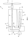
FIG. 1 illustrates a schematic view of an engine assembly, in accordance with one or more embodiments of the present disclosure. -
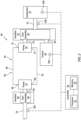
FIG. 2 schematically illustrates a gearbox assembly for the engine assembly ofFIG. 1 , in accordance with one or more embodiments of the present disclosure. -
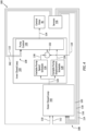
FIG. 3 schematically illustrates a variable displacement pump and a variable displacement control assembly for the gearbox assembly ofFIG. 2 , in accordance with one or more embodiments of the present disclosure. -
FIG. 4 schematically illustrates a control architecture for controlling a displacement of a variable displacement pump ofFIG. 3 using the variable displacement control assembly, in accordance with one or more embodiments of the present disclosure. -
FIG. 1 illustrates anengine assembly 10. Theengine assembly 10 may form a portion of a propulsion system for an aircraft. Briefly, the aircraft may be a fixed-wing aircraft (e.g., an airplane), a rotary-wing aircraft (e.g., a helicopter), a tilt-rotor aircraft, a tilt-wing aircraft, or another aerial vehicle. Moreover, the aircraft may be a manned aerial vehicle or an unmanned aerial vehicle (UAV, e.g., a drone). Theengine assembly 10 may also form a portion of an auxiliary power unit (APU) or onboard generator for an aircraft. However, the present disclosure is not limited to any particular application of theengine assembly 10. Theengine assembly 10 ofFIG. 1 includes anengine 12, arotational load 14, acompressor section 16, aturbine section 18, and arotational assembly 20. - The
engine 12 ofFIG. 1 is configured as a rotary intermittent internal combustion engine, which intermittent internal combustion engine includes arotor assembly 22 and anengine shaft 24. As will be described in further detail, therotor assembly 22 may be configured, for example, as a Wankel engine in which an eccentric rotor configuration is used to convert fluid pressure into rotational motion. - The
rotor assembly 22 is coupled to theengine shaft 24 and configured to drive theengine shaft 24 for rotation about arotational axis 26. Theengine shaft 24 is coupled to therotational load 14 such that rotation of theengine shaft 24 by therotor assembly 22 drives rotation of therotational load 14. Theengine shaft 24 may be coupled to therotational load 14 by a speed-reducinggear assembly 28 of theengine 12. The speed-reducinggear assembly 28 may be configured to effect rotation of therotational load 14 at a reduced rotational speed relative to theengine shaft 24. Therotational load 14 ofFIG. 1 is configured as a propeller. Rotation of the propeller by theengine 12 may generate thrust for an aircraft which includes theengine assembly 10. Theengine assembly 10 of the present disclosure may additionally or alternatively be configured to drive other rotational loads, such as, but not limited to, an electrical generator(s), a rotational accessory load, a rotor mast, a compressor, or any other suitable rotational load configuration. - The
compressor section 16, theturbine section 18, and therotational assembly 20 form a turbo-compressor for theengine assembly 10. Therotational assembly 20 ofFIG. 1 includes ashaft 30, abladed compressor rotor 32 of thecompressor section 16, and abladed turbine rotor 34 of theturbine section 18. Theshaft 30 is connected to the bladedturbine rotor 34. Theshaft 30 and thebladed turbine rotor 34 are mounted to rotation about arotational axis 36. In operation, ambient air is received by thecompressor section 16. The air is compressed by rotation of the bladedcompressor rotor 32 and directed to anair intake 37A of theengine 12. Combustion exhaust gases from anexhaust 37B of theengine 12 are directed to theturbine section 18 causing the bladedturbine rotor 34 to rotate and rotationally drive theshaft 30. Theshaft 30 is coupled with thebladed compressor rotor 32 by agearbox assembly 38 of theengine assembly 10 to drive rotation of the bladedcompressor rotor 32, as will be discussed below in further detail. -
FIG. 2 schematically illustrates thegearbox assembly 38. Thegearbox assembly 38 ofFIG. 2 includes afirst gearbox 40, asecond gearbox 42, and ahydrostatic transmission assembly 44. Thegearbox assembly 38 may further include acontroller 46. - The
first gearbox 40 includes afirst gear assembly 48 coupled with theengine shaft 24 and thehydrostatic transmission assembly 44. Thefirst gear assembly 48 may be configured as an epicyclic gear assembly (e.g., a planetary gear assembly). Thefirst gear assembly 48, however, is not limited to any particular gear configuration. - The
second gearbox 42 includes asecond gear assembly 50 coupled with the rotational assembly 20 (e.g., the shaft 30), thehydrostatic transmission assembly 44, and the bladed compressor rotor 32 (e.g., by an output shaft 52). For example, thesecond gear assembly 50 may be configured to drive rotation of the bladedcompressor rotor 32 in response to input rotational force from the bladedturbine rotor 34 and/or thehydrostatic transmission assembly 44. Thesecond gear assembly 50 may be configured as an epicyclic gear assembly (e.g., a planetary gear assembly). Thesecond gear assembly 50, however, is not limited to any particular gear configuration. - The
hydrostatic transmission assembly 44 ofFIG. 2 includes afirst pump 54 and asecond pump 56. Thefirst pump 54 and thesecond pump 56 are coupled in bi-directional fluid communication by aconduit circuit 58. Theconduit circuit 58 includes a first conduit portion 60 (e.g., a supply conduit or a return conduit) and a second conduit portion 62 (e.g., a supply conduit or a return conduit). Each of thefirst conduit portion 60 and thesecond conduit portion 62 extends between and to thefirst pump 54 and thesecond pump 56. Theconduit circuit 58 is configured to direct a fluid from thefirst pump 54 to thesecond pump 56 and from thesecond pump 56 to thefirst pump 54. Theconduit circuit 58 may include any suitable pipe, hose, tube, and/or other conduit to direct the fluid between thefirst pump 54 and thesecond pump 56. The fluid for thehydrostatic transmission assembly 44 may be a hydraulic fluid such as, but not limited to, oil or another lubricant. However, the present disclosure is not limited to any particular fluid for thehydrostatic transmission assembly 44. - The
first pump 54 is coupled with thefirst gear assembly 48, for example, by adrive shaft 64. Thefirst pump 54 includes afluid outlet 66 and afluid inlet 68. Thefluid outlet 66 is coupled with thefirst conduit portion 60. Thefluid inlet 68 is coupled with thesecond conduit portion 62. Thefirst pump 54 is configured as a variable displacement pump, as will be discussed below in further detail. For example, thefirst pump 54 may be configured as a variable displacement piston pump. - The
second pump 56 is coupled with thesecond gear assembly 50, for example, by adrive shaft 70. Thesecond pump 56 includes afluid outlet 72 and afluid inlet 74. Thefluid outlet 72 is coupled with thesecond conduit portion 62. Thefluid inlet 74 is coupled with thefirst conduit portion 60. Thesecond pump 56 may be configured as a fixed displacement pump. For example, thesecond pump 56 may be configured as a fixed displacement piston pump. However, thesecond pump 56 of the present disclosure is not limited to fixed displacement pump configurations and thesecond pump 56 may alternatively be configured as a variable displacement pump similar to thefirst pump 54. - In operation, the
hydrostatic transmission assembly 44 facilitates extraction and use ofexcess engine 12 power for the rotational assembly 20 (e.g., the bladed compressor rotor 32), thereby improving the efficiency of the engine assembly 10 (seeFIG. 1 ). Rotation of theengine shaft 24 drives operation of thefirst pump 54 through thefirst gear assembly 48. For example, thefirst gear assembly 48 may drive thedrive shaft 64 at a reduced rotational speed relative to theengine shaft 24. In response to the rotation of thedrive shaft 64, thefirst pump 54 pumps the fluid through theconduit circuit 58. The flow of the fluid through theconduit circuit 58 drives thesecond pump 56 to apply a rotational force to thesecond gear assembly 50 with thedrive shaft 70, thereby driving thebladed compressor rotor 32 cooperatively with the bladedturbine rotor 34. During some operating conditions of theengine assembly 10, thehydrostatic transmission assembly 44 may alternatively facilitate extraction and use ofbladed turbine rotor 34 power for theengine shaft 24. Rotation of theshaft 30 drives operation of thesecond pump 56 through thesecond gear assembly 50. In response to the rotation of thedrive shaft 70, thesecond pump 56 pumps the fluid through theconduit circuit 58. The flow of the fluid through theconduit circuit 58 drives thefirst pump 54 to apply a rotational force to thefirst gear assembly 48 with thedrive shaft 64, thereby applying a rotational force to theengine shaft 24. - The
controller 46 includes aprocessor 76 connected in signal communication withmemory 78. Theprocessor 76 may include any type of computing device, computational circuit, processor(s), CPU, computer, or the like capable of executing a series of instructions that are stored in thememory 78. Instructions can be directly executable or can be used to develop executable instructions. For example, instructions can be realized as executable or non-executable machine code or as instructions in a high-level language that can be compiled to produce executable or non-executable machine code. Further, instructions also can be realized as or can include data. Computer-executable instructions also can be organized in any format, including routines, subroutines, programs, data structures, objects, modules, applications, applets, functions, etc. The instructions may include an operating system, and/or executable software modules such as program files, system data, buffers, drivers, utilities, and the like. The executable instructions may apply to any functionality described herein to enable thegearbox assembly 38 to accomplish the same algorithmically and/or by coordination of components of thegearbox assembly 38. Thememory 78 may include a single memory device or a plurality of memory devices; e.g., a computer-readable storage device that can be read, written, or otherwise accessed by a general purpose or special purpose computing device, including any processing electronics and/or processing circuitry capable of executing instructions. The present disclosure is not limited to any particular type of memory device, which may be non-transitory, and may include read-only memory, random access memory, volatile memory, non-volatile memory, static memory, dynamic memory, flash memory, cache memory, volatile or non-volatile semiconductor memory, optical disk storage, magnetic disk storage, magnetic tape, other magnetic storage devices, or any other medium capable of storing one or more instructions, and/or any device that stores digital information. The memory device(s) may be directly or indirectly coupled to thecontroller 46. Thecontroller 46 may include, or may be in communication with, an input device that enables a user to enter data and/or instructions, and may include, or be in communication with, an output device configured, for example to display information (e.g., a visual display or a printer), or to transfer data, etc. Communications between thecontroller 46 and other electrical and/or electronic components (e.g., controllers, sensors, etc.) may be via a hardwire connection or via a wireless connection. A person of skill in the art will recognize that portions of thecontroller 46 may assume various forms (e.g., digital signal processor, analog device, etc.) capable of performing the functions described herein. - The
controller 46 may form or otherwise be part of an electronic engine controller (EEC) for the engine assembly 10 (seeFIG. 1 ). The EEC may control operating parameters of theengine 12 including, but not limited to, fuel flow,engine shaft 24 torque and/or rotation speed,bladed compressor rotor 32 rotation speed, etc. so as to control an engine power or performance of theengine assembly 10. For example, the EEC may modulate fuel flow to theengine 12 to obtain a desired output power of theengine 12. Thecontroller 46 may include or otherwise be connected in signal communication with one or more sensors to measure and/or determine operational parameters of theengine assembly 10. In some embodiments, the EEC may be part of a full authority digital engine control (FADEC) system. -
FIG. 3 schematically illustrates thefirst pump 54 and a variabledisplacement control assembly 80 for thefirst pump 54. Thefirst pump 54 ofFIG. 3 includes aswash plate 82. Theswash plate 82 may be selectively positioned (e.g., by the variable displacement control assembly 80) to control a displacement (e.g., a pumping volume) of thefirst pump 54. For example, theswash plate 82 may control a piston stroke length for the pumping pistons of thefirst pump 54. The present disclosure, however, is not limited to the use of a swash plate for controlling a variable displacement of thefirst pump 54, and other configurations of variable displacement pumps may alternatively be used. The variabledisplacement control assembly 80 ofFIG. 3 includes apiston assembly 84 and a control valve 86 (e.g., a servo valve). Thepiston assembly 84 includes a piston 88 and ahousing 90. The piston 88 extends between and to afirst piston end 92 and asecond piston end 94. Thefirst piston end 92 is disposed within and surrounded by thehousing 90. Thefirst piston end 92 and thehousing 90 form afirst chamber 96 and asecond chamber 98. Thefirst chamber 96 is connected in fluid communication with theconduit circuit 58. Thesecond chamber 98 is connected in fluid communication with thecontrol valve 86. Thesecond piston end 94 is disposed at (e.g., on, adjacent, or proximate) theswash plate 82. Thecontrol valve 86 is connected in fluid communication with theconduit circuit 58 and thesecond chamber 98. Thecontrol valve 86 is configured to control a pressure of fluid in thesecond chamber 98 to control a position of the piston 88, and thereby control a position of theswash plate 82. For example, thecontrol valve 86 may be connected in signal communication with thecontroller 46 and thecontroller 46 may control a position of thecontrol valve 86 to selectively position theswash plate 82 with the piston 88. The position of theswash plate 82 to control the displacement of thefirst pump 54 facilitates control of the fluid flow rate in theconduit circuit 58. The present disclosure, however, is not limited to the foregoing exemplary configuration of thefirst pump 54 and the variabledisplacement control assembly 80. -
FIG. 4 illustrates a diagram of acontrol architecture 100 for selectively controlling the displacement of the first pump 54 (e.g., with the variable displacement control assembly 80) (seeFIGS. 2 and3 ). Thecontrol architecture 100 may be executed by the controller 46 (e.g., the processor 76) using instructions stored in the memory 78 (seeFIG. 2 ). Thecontrol architecture 100 ofFIG. 4 includes an outerclosed loop 102 and an innerclosed loop 104. Referring additionally toFIG 2 , thecontroller 46 may be connected in signal communication with a plurality ofsensors 106 of theengine assembly 10. Examples of thesensors 106 include, but are not limited to, temperature sensors, pressure sensors, rotation speed sensors, torque sensors, or component position sensors. The controller 46 (e.g., the processor 76) may execute thecontrol architecture 100 using signals (e.g., measurement signals) from one or more of thesensors 106. - The outer
closed loop 102 is configured to identify a target rotation speed for the rotational assembly 20 (e.g., the bladed compressor rotor 32) (seeFIGS. 1 and2 ). The outerclosed loop 102 receivesoperational parameter inputs 108 for theengine 12 and the compressor section 16 (e.g., from the sensors 106). Theoperational parameters 108 include, but are not limited to, an engine (e.g., engine shaft 24)rotation speed 110, an engine (e.g., engine shaft 24) torque or engine power (e.g.,engine shaft 24 horsepower) 112, acompressor outlet pressure 114, acompressor outlet temperature 116, acompressor inlet pressure 118, and acompressor inlet temperature 120. The outerclosed loop 102 identifies atarget rotation speed 122 for the rotational assembly 20 (e.g., the bladed compressor rotor 32) using theoperational parameters 108. For example, the outerclosed loop 102 may identify thetarget rotation speed 122 to provide optimal air flow for theengine 12 while preventing thecompressor section 16 from exceeding compressor surge and/or compressor stall operating limits. Thetarget rotation speed 122 may be identified from predetermined target rotation speed values (e.g., look-up tables or other databases) stored inmemory 78. Alternatively, the target rotation speed may be calculated, modeled, or otherwise determined by thecontroller 46 using the operatingparameters 108. Routine experimentation and/or analysis may be performed by a person of ordinary skill in the art to determine an optimal range of compressor target rotation speeds for theoperational parameters 108 discussed above, in accordance with and as informed by one or more aspects of the present disclosure. - The inner
closed loop 104 is configured to identify a target fluid flow rate for thefirst pump 54 and to facilitate generation of a control signal (e.g., an electrical control current) for thecontrol valve 86 to effect the target fluid flow rate of the first pump 54 (seeFIGS. 2 and3 ). The target fluid flow rate may be understood as a function of speed and displacement for thefirst pump 54. For example, thecontroller 46 may execute the innerclosed loop 104 and generate acontrol signal 124 for thecontrol valve 86 to cause thecontrol valve 86 to position the piston 88 and, subsequently, theswash plate 82 to control the displacement and, hence, the fluid flow rate of the first pump 54 (seeFIGS. 2 and3 ). The fluid flow rate of thefirst pump 54 may, in turn, control the rotational force applied to theengine 12 or therotational assembly 20 by thehydrostatic transmission assembly 44, as described above. The innerclosed loop 104 applies thetarget rotation speed 122 from the outerclosed loop 102 to aspeed schedule 126 for thefirst pump 54 and adisplacement schedule 128 for thefirst pump 54. Thespeed schedule 126 identifies atarget speed 130 for thefirst pump 54 using thetarget rotation speed 122. The innerclosed loop 104 identifies aspeed difference 132 between thetarget speed 130 and theengine rotation speed 110. Thedisplacement schedule 128 identifies atarget displacement 134 for thefirst pump 54 using thetarget rotation speed 122. The innerclosed loop 104 applies thespeed difference 132 and thetarget displacement 134 to apump control element 136 which generates or otherwise controls the generation of thecontrol signal 124 by thecontroller 46. Thepump control element 136 additionally receivesoperational parameter inputs 138 for theengine 12 and the compressor section 16 (e.g., from the sensors 106). Theoperational parameters 138 include, but are not limited to, theengine rotation speed 110 and arotation speed 142 of the rotational assembly 20 (e.g., thebladed compressor rotor 32; seeFIG. 1 ). Using thespeed difference 132, thetarget displacement 134, and theoperational parameters 138, thepump control element 136 identifies the control signal 124 (e.g., a magnitude of the control signal 124). Thetarget speed 130, thetarget displacement 134, and/or thecontrol signal 124 may be identified from predetermined values (e.g., look-up tables or other databases) stored inmemory 78. Alternatively, thetarget speed 130, thetarget displacement 134, and/or thecontrol signal 124 speed may be calculated, modeled, or otherwise determined by thecontroller 46. Routine experimentation and/or analysis may be performed by a person of ordinary skill in the art to determine values of thetarget speed 130, thetarget displacement 134, and/or thecontrol signal 124 for various configurations and operating conditions of theengine assembly 10, in accordance with and as informed by one or more aspects of the present disclosure. - The configuration outer
closed loop 102 and the innerclosed loop 104 of thecontrol architecture 100 facilitates feedforward control of thefirst pump 54 by thepump control element 136, for example, by accounting for changes (e.g., disturbances) in air pressure and air temperature at thecompressor section 16 inlet (seeFIG. 1 ). Accordingly, the presentdisclosure control architecture 100 may provide improved input disturbance compensation for control of the compressor section 16 (e.g., the bladed compressor rotor 32), compared to conventional control systems of which we are aware, while also facilitating prevention or reduced likelihood of compressor surge or compressor stall conditions. - While the principles of the disclosure have been described above in connection with specific apparatuses and methods, it is to be clearly understood that this description is made only by way of example and not as limitation on the scope of the disclosure. Specific details are given in the above description to provide a thorough understanding of the embodiments. However, it is understood that the embodiments may be practiced without these specific details.
- It is noted that the embodiments may be described as a process which is depicted as a flowchart, a flow diagram, a block diagram, etc. Although any one of these structures may describe the operations as a sequential process, many of the operations can be performed in parallel or concurrently. In addition, the order of the operations may be rearranged. A process may correspond to a method, a function, a procedure, a subroutine, a subprogram, etc.
- The singular forms "a," "an," and "the" refer to one or more than one, unless the context clearly dictates otherwise. For example, the term "comprising a specimen" includes single or plural specimens and is considered equivalent to the phrase "comprising at least one specimen." The term "or" refers to a single element of stated alternative elements or a combination of two or more elements unless the context clearly indicates otherwise. As used herein, "comprises" means "includes." Thus, "comprising A or B," means "including A or B, or A and B," without excluding additional elements.
- It is noted that various connections are set forth between elements in the present description and drawings (the contents of which are included in this disclosure by way of reference). It is noted that these connections are general and, unless specified otherwise, may be direct or indirect and that this specification is not intended to be limiting in this respect. Any reference to attached, fixed, connected, or the like may include permanent, removable, temporary, partial, full and/or any other possible attachment option.
- As used herein, the terms "comprise", "comprising", or any other variation thereof, are intended to cover a non-exclusive inclusion, such that a process, method, article, or apparatus that comprises a list of elements does not include only those elements but may include other elements not expressly listed or inherent to such process, method, article, or apparatus.
- While various inventive aspects, concepts and features of the disclosures may be described and illustrated herein as embodied in combination in the exemplary embodiments, these various aspects, concepts, and features may be used in many alternative embodiments, either individually or in various combinations and sub-combinations thereof. Unless expressly excluded herein all such combinations and sub-combinations are intended to be within the scope of the present application. Still further, while various alternative embodiments as to the various aspects, concepts, and features of the disclosures--such as alternative materials, structures, configurations, methods, devices, and components, and so on--may be described herein, such descriptions are not intended to be a complete or exhaustive list of available alternative embodiments, whether presently known or later developed. Those skilled in the art may readily adopt one or more of the inventive aspects, concepts, or features into additional embodiments and uses within the scope of the present application even if such embodiments are not expressly disclosed herein. For example, in the exemplary embodiments described above within the Detailed Description portion of the present specification, elements may be described as individual units and shown as independent of one another to facilitate the description. In alternative embodiments, such elements may be configured as combined elements.
Claims (15)
- An engine assembly (10) for an aircraft propulsion system, the engine assembly (10) comprising:an engine (12) including an engine shaft (24), an air intake (37A), and an exhaust (37B);a rotational assembly (20) including a shaft (30), a bladed compressor rotor (32), and a bladed turbine rotor (34), the shaft (30) interconnects the bladed compressor rotor (32) and the bladed turbine rotor (34), the bladed compressor rotor (32) forms a portion of a compressor section (16) of the engine assembly (10), the compressor section (16) is configured to direct a compressed air to the air intake (37A), the bladed turbine rotor (34) forms a portion of a turbine section (18) of the engine assembly (10), and the turbine section (18) is configured to receive an exhaust gas from the exhaust (37B);a gearbox assembly (38) coupling the engine shaft (24) and the rotational assembly (20), the gearbox assembly (38) includes a transmission assembly (44), the transmission assembly (44) includes a first pump (54), a second pump (56), and a conduit circuit (58) connecting the first pump (54) and the second pump (56) in fluid communication, the first pump (54) is coupled with the engine shaft (24), the first pump (54) is a variable displacement pump, and the second pump (56) is coupled with the rotational assembly (20); anda controller (46) including a processor (76) in communication with a non-transitory memory (78) storing instructions, the instructions, when executed by the processor (76), cause the processor (76) to execute a control architecture (100) for the first pump (54) by:identifying a target rotation speed (122) for the rotational assembly (20) with an outer closed loop (102) of the control architecture (100);identifying a control signal (124) with an inner closed loop (104) of the control architecture (100) using the target rotation speed (122); andcontrolling a displacement of the first pump (54) using the control signal (124).
- The engine assembly (10) of claim 1, wherein the first pump (54) includes a swash plate (82), and the swash plate (82) is selectively positionable to vary the displacement of the first pump (54).
- The engine assembly (10) of claim 2, wherein the transmission assembly (44) further includes a variable displacement control assembly (80), the variable displacement control assembly (80) includes a piston assembly (84) and a control valve (86), the piston assembly (84) includes a piston (88) coupled with the swash plate (82), and the control valve (86) is configured to control a position of the piston (88) to selectively position the swash plate (82), optionally wherein:
controlling the displacement of the first pump (54) using the control signal (124) includes directing the control signal (124) to the control valve (86) to control a position of the control valve (86). - The engine assembly (10) of any preceding claim, wherein identifying the target rotation speed (122) for the rotational assembly (20) with the outer closed loop (102) includes identifying the target rotation speed (122) using a compressor outlet pressure (114), a compressor outlet temperature (116), a compressor inlet pressure (118), and/or a compressor inlet temperature (120) for the compressor section (16).
- The engine assembly (10) of any preceding claim, wherein identifying the target rotation speed for the rotational assembly (20) with the outer closed loop (102) includes identifying the target rotation speed (122) using an engine torque (112) and/or a rotation speed (110) of the engine shaft (24).
- The engine assembly (10) of any preceding claim, wherein identifying the control signal (124) with the inner closed loop (104) includes identifying the control signal (124) using a rotation speed (142) of the rotational assembly (20) and a or the rotation speed (110) of the engine shaft (24).
- An engine assembly (10) for an aircraft propulsion system, the engine assembly (10) comprising:an engine (12) including an engine shaft (24) and an air intake (37A);a rotational assembly (20) including a bladed compressor rotor (32), the bladed compressor rotor (32) forms a portion of a compressor section (16) of the engine assembly (10), and the compressor section (16) is configured to direct a compressed air to the air intake (37A);a gearbox assembly (38) coupling the engine shaft (24) and the rotational assembly (20), the gearbox assembly (38) includes a transmission assembly (44), the transmission assembly (44) includes a first pump (54), a second pump (56), and a conduit circuit (58) connecting the first pump (54) and the second pump (56) in fluid communication, the first pump (54) is coupled with the engine shaft (24), the first pump (54) is a variable displacement pump, and the second pump (56) is coupled with the rotational assembly (20); anda controller (46) including a processor (76) in communication with a non-transitory memory (78) storing instructions, the instructions, when executed by the processor (76), cause the processor (76) to execute a control architecture (100) for the first pump (54) by:identifying a target rotation speed (122) for the rotational assembly (20) with an outer closed loop (102) of the control architecture (100) using a compressor outlet pressure (114) and a compressor inlet pressure (118) for the compressor section (16);identifying a control signal (124) with an inner closed loop (104) of the control architecture (100) using the target rotation speed (122); andcontrolling a displacement of the first pump (54) using the control signal (124).
- The engine assembly (10) of any preceding claim, wherein the engine shaft (24) has a first rotational axis (26), the bladed compressor rotor (32) has a second rotational axis (36), and the first rotational axis (26) is different than the second rotational axis (36).
- The engine assembly (10) of any preceding claim, further comprising a propeller (14) coupled with the engine shaft (24).
- The engine assembly (10) of any preceding claim, wherein identifying the control signal (124) with the inner closed loop (104) includes identifying the control signal (124) using a target displacement (134) for the first pump (54) and a speed difference (132) between a target speed (130) for the first pump (54) and a rotation speed (110) of the engine shaft (24).
- The engine assembly (10) of claim 10, wherein:the inner closed loop (104) applies the target rotation speed (122) from the outer closed loop (102) to a speed schedule (126) for the first pump (54), and optionally to a displacement schedule (128) for the first pump (54); andthe speed schedule (126) identifies the target speed (130) for the first pump (54) using the target rotation speed (122) for the rotational assembly (20) and the rotation speed (110) of the engine shaft (24).
- An engine assembly (10) for an aircraft propulsion system, the engine assembly (10) comprising:an engine (12) including an engine shaft (24) and an air intake (37A);a rotational assembly (20) including a bladed compressor rotor (32), the bladed compressor rotor (32) forms a portion of a compressor section (16) of the engine assembly (10), and the compressor section (16) is configured to direct a compressed air to the air intake (37A);a gearbox assembly (38) coupling the engine shaft (24) and the rotational assembly (20), the gearbox assembly (38) includes a transmission assembly (44), the transmission assembly (44) includes a first pump (54), a second pump (56), a conduit circuit (58) connecting the first pump (54) and the second pump (56) in fluid communication, and a variable displacement control assembly (80), the first pump (54) is coupled with the engine shaft (24), the first pump (24) includes a swash plate (82), the swash plate (82) is selectively positionable to vary a displacement of the first pump (54), and the second pump (56) is coupled with the rotational assembly (20), the variable displacement control assembly (80) includes a piston assembly (84) and a control valve (86), the piston assembly (84) includes a piston (88) coupled with the swash plate (82), and the control valve (86) is configured to control a position of the piston (88) to selectively position the swash plate (82); anda controller (46) including a processor (76) in communication with a non-transitory memory (78) storing instructions, the instructions, when executed by the processor (76), cause the processor (76) to execute a control architecture (100) for the first pump (54) by:identifying a target rotation speed (122) for the rotational assembly (20) with an outer closed loop (102) of the control architecture (100) using a compressor outlet pressure (114) and a compressor inlet pressure (118) for the compressor section (16);identifying a control signal (124) with an inner closed loop (104) of the control architecture (100) using the target rotation speed (122); andcontrolling a rotational force applied to the rotational assembly (20) by directing the control signal (124) to the control valve (86) to control a position of the control valve (86), the piston (88), and the swash plate (82).
- The engine assembly (10) of any preceding claim, wherein the first pump (54) is coupled to the engine shaft (24) by a first gear assembly (48).
- The engine assembly (10) of any preceding claim, wherein the second pump (56) is coupled to the rotational assembly (20) by a second gear assembly (50).
- The engine assembly (10) of any preceding claim, wherein the second pump (56) is a fixed displacement pump.
Applications Claiming Priority (1)
| Application Number | Priority Date | Filing Date | Title |
|---|---|---|---|
| US18/228,424 US12152531B1 (en) | 2023-07-31 | 2023-07-31 | Transmission assembly for an aircraft engine assembly and architecture for controlling same |
Publications (1)
| Publication Number | Publication Date |
|---|---|
| EP4513019A1 true EP4513019A1 (en) | 2025-02-26 |
Family
ID=92141964
Family Applications (1)
| Application Number | Title | Priority Date | Filing Date |
|---|---|---|---|
| EP24191859.8A Pending EP4513019A1 (en) | 2023-07-31 | 2024-07-30 | Transmission assembly for an aircraft engine assembly and architecure for controlling same |
Country Status (3)
| Country | Link |
|---|---|
| US (1) | US12152531B1 (en) |
| EP (1) | EP4513019A1 (en) |
| CA (1) | CA3251203A1 (en) |
Citations (4)
| Publication number | Priority date | Publication date | Assignee | Title |
|---|---|---|---|---|
| JP2006242051A (en) * | 2005-03-02 | 2006-09-14 | Mitsui Eng & Shipbuild Co Ltd | Engine surplus exhaust energy recovery system |
| US20150378327A1 (en) * | 2014-06-30 | 2015-12-31 | General Electric Company | Multivariable feedforward control |
| US20200307811A1 (en) * | 2017-10-11 | 2020-10-01 | Purdue Research Foundation | Aviation hydraulic propulsion system utilizing secondary controlled drives |
| US20200386149A1 (en) * | 2019-06-04 | 2020-12-10 | Hamilton Sundstrand Corporation | Turbo-compressors for internal combustion engines |
Family Cites Families (16)
| Publication number | Priority date | Publication date | Assignee | Title |
|---|---|---|---|---|
| US6273076B1 (en) * | 1997-12-16 | 2001-08-14 | Servojet Products International | Optimized lambda and compression temperature control for compression ignition engines |
| US8572974B2 (en) | 2009-07-31 | 2013-11-05 | Hamilton Sundstrand Corporation | Variable speed and displacement electric fluid delivery system for a gas turbine engine |
| US20130260940A1 (en) * | 2012-03-30 | 2013-10-03 | Hamilton Sundstrand Corporation | Gearing Assembly |
| US12330657B2 (en) * | 2011-12-02 | 2025-06-17 | Power Technology Holdings Llc | Hybrid vehicle drive system and method for fuel reduction during idle |
| US10480421B2 (en) * | 2016-08-04 | 2019-11-19 | Pratt & Whitney Canada Corp. | System and method for an engine controller based on acceleration power |
| US10634049B2 (en) * | 2017-01-16 | 2020-04-28 | Pratt & Whitney Canada Corp. | Turbofan engine assembly with intercooler |
| US10968825B2 (en) * | 2018-04-19 | 2021-04-06 | The Boeing Company | Flow multiplier systems for aircraft |
| US10738749B1 (en) * | 2019-01-18 | 2020-08-11 | Pratt & Whitney Canada Corp. | Method of using heat from fuel of common-rail injectors |
| US11408345B2 (en) * | 2019-08-29 | 2022-08-09 | Rolls-Royce Corporation | Oil tank for geared turbofan engine |
| US20210071567A1 (en) * | 2019-09-10 | 2021-03-11 | Hamilton Sundstrand Corporation | Bi-directional pump/motor |
| US20220090538A1 (en) * | 2020-09-21 | 2022-03-24 | James Hall Carrow | Zero Emissions Turbofan [With Aeroderivative Power Generation and Marine Applications] |
| US11279366B1 (en) * | 2020-11-17 | 2022-03-22 | Deere & Company | Feedforward mechanism with signal decay for torque adjustment in diesel engine operation |
| CN112628005B (en) | 2020-12-09 | 2022-11-29 | 潍柴动力股份有限公司 | Engine rotating speed closed-loop control method and device, storage medium and electronic equipment |
| GB2620438B (en) * | 2022-07-08 | 2025-04-16 | Gkn Aerospace Services Ltd | A controllably variable power unit for an aircraft |
| US12320412B2 (en) * | 2022-09-07 | 2025-06-03 | Regents Of The University Of Minnesota | Axial piston variable displacement hydraulic devices, such as hydraulic motors, and methods of operating same |
| GB202214143D0 (en) * | 2022-09-28 | 2022-11-09 | Rolls Royce Plc | Gas turbine engine with an improved thermal management system |
-
2023
- 2023-07-31 US US18/228,424 patent/US12152531B1/en active Active
-
2024
- 2024-07-29 CA CA3251203A patent/CA3251203A1/en active Pending
- 2024-07-30 EP EP24191859.8A patent/EP4513019A1/en active Pending
Patent Citations (4)
| Publication number | Priority date | Publication date | Assignee | Title |
|---|---|---|---|---|
| JP2006242051A (en) * | 2005-03-02 | 2006-09-14 | Mitsui Eng & Shipbuild Co Ltd | Engine surplus exhaust energy recovery system |
| US20150378327A1 (en) * | 2014-06-30 | 2015-12-31 | General Electric Company | Multivariable feedforward control |
| US20200307811A1 (en) * | 2017-10-11 | 2020-10-01 | Purdue Research Foundation | Aviation hydraulic propulsion system utilizing secondary controlled drives |
| US20200386149A1 (en) * | 2019-06-04 | 2020-12-10 | Hamilton Sundstrand Corporation | Turbo-compressors for internal combustion engines |
Also Published As
| Publication number | Publication date |
|---|---|
| CA3251203A1 (en) | 2025-06-05 |
| US12152531B1 (en) | 2024-11-26 |
Similar Documents
| Publication | Publication Date | Title |
|---|---|---|
| CA2976982C (en) | Power plant thrust management system for turboprop engines | |
| EP4530452A1 (en) | System and method for performing an actuator range check for an intercooler flow control assembly of an aircraft propulsion system | |
| US11668253B2 (en) | System and method for providing in-flight reverse thrust for an aircraft | |
| EP3406902A1 (en) | Variable displacement fuel pump | |
| EP4534831A2 (en) | Engine assembly for an aircraft propulsion system | |
| US12152531B1 (en) | Transmission assembly for an aircraft engine assembly and architecture for controlling same | |
| EP3748143B1 (en) | Turbo-compressors for internal combustion engines | |
| EP4459157A1 (en) | Torque sensor for an aircraft propulsion system gearbox assembly | |
| EP4357247A1 (en) | Aircraft propulsion system with intermittent combustion engine, hydraulic motor, and cooling system | |
| US10082184B2 (en) | System and method for eliminating adverse clutch vibratory responses | |
| EP4549717A2 (en) | Gas turbine engine fuel system for an aircraft propulsion system | |
| US12624664B1 (en) | Overspeed protection for a turbocompressor of an aircraft powerplant assembly | |
| EP4474630A1 (en) | System and method for controlling engines of a multi-engine aircraft engine assembly | |
| EP4733563A1 (en) | Systems and methods for operating an aircraft engine using multiple fuel types | |
| EP4733562A2 (en) | Systems and methods for operating an aircraft engine using multiple fuel types | |
| EP4733564A1 (en) | Systems and methods for operating an aircraft engine using multiple fuel types | |
| EP4733560A2 (en) | Systems and methods for operating an aircraft engine using multiple fuel types | |
| US12631148B2 (en) | Systems and methods for operating an aircraft engine using multiple fuel types | |
| US12509236B1 (en) | Control assembly for aircraft propulsion systems | |
| US12630299B2 (en) | System and method for controlling engines of a multi-engine aircraft engine assembly | |
| EP4631860A1 (en) | Heat exchanger cooling assembly for an aircraft propulsion system | |
| US20260117710A1 (en) | Systems and methods for operating an aircraft engine using multiple fuel types | |
| CA3270119A1 (en) | Heat exchanger cooling assembly for an aircraft propulsion system |
Legal Events
| Date | Code | Title | Description |
|---|---|---|---|
| PUAI | Public reference made under article 153(3) epc to a published international application that has entered the european phase |
Free format text: ORIGINAL CODE: 0009012 |
|
| STAA | Information on the status of an ep patent application or granted ep patent |
Free format text: STATUS: THE APPLICATION HAS BEEN PUBLISHED |
|
| AK | Designated contracting states |
Kind code of ref document: A1 Designated state(s): AL AT BE BG CH CY CZ DE DK EE ES FI FR GB GR HR HU IE IS IT LI LT LU LV MC ME MK MT NL NO PL PT RO RS SE SI SK SM TR |
|
| STAA | Information on the status of an ep patent application or granted ep patent |
Free format text: STATUS: REQUEST FOR EXAMINATION WAS MADE |
|
| 17P | Request for examination filed |
Effective date: 20250826 |