EP4513014A1 - Internal combustion engine system - Google Patents
Internal combustion engine system Download PDFInfo
- Publication number
- EP4513014A1 EP4513014A1 EP23192648.6A EP23192648A EP4513014A1 EP 4513014 A1 EP4513014 A1 EP 4513014A1 EP 23192648 A EP23192648 A EP 23192648A EP 4513014 A1 EP4513014 A1 EP 4513014A1
- Authority
- EP
- European Patent Office
- Prior art keywords
- cylinder
- intake
- ice
- cylinders
- piston
- Prior art date
- Legal status (The legal status is an assumption and is not a legal conclusion. Google has not performed a legal analysis and makes no representation as to the accuracy of the status listed.)
- Pending
Links
Images


Classifications
-
- F—MECHANICAL ENGINEERING; LIGHTING; HEATING; WEAPONS; BLASTING
- F02—COMBUSTION ENGINES; HOT-GAS OR COMBUSTION-PRODUCT ENGINE PLANTS
- F02B—INTERNAL-COMBUSTION PISTON ENGINES; COMBUSTION ENGINES IN GENERAL
- F02B43/00—Engines characterised by operating on gaseous fuels; Plants including such engines
- F02B43/10—Engines or plants characterised by use of other specific gases, e.g. acetylene, oxyhydrogen
-
- F—MECHANICAL ENGINEERING; LIGHTING; HEATING; WEAPONS; BLASTING
- F02—COMBUSTION ENGINES; HOT-GAS OR COMBUSTION-PRODUCT ENGINE PLANTS
- F02D—CONTROLLING COMBUSTION ENGINES
- F02D41/00—Electrical control of supply of combustible mixture or its constituents
- F02D41/0002—Controlling intake air
- F02D41/0007—Controlling intake air for control of turbo-charged or super-charged engines
-
- F—MECHANICAL ENGINEERING; LIGHTING; HEATING; WEAPONS; BLASTING
- F02—COMBUSTION ENGINES; HOT-GAS OR COMBUSTION-PRODUCT ENGINE PLANTS
- F02B—INTERNAL-COMBUSTION PISTON ENGINES; COMBUSTION ENGINES IN GENERAL
- F02B25/00—Engines characterised by using fresh charge for scavenging cylinders
- F02B25/02—Engines characterised by using fresh charge for scavenging cylinders using unidirectional scavenging
- F02B25/04—Engines having ports both in cylinder head and in cylinder wall near bottom of piston stroke
-
- F—MECHANICAL ENGINEERING; LIGHTING; HEATING; WEAPONS; BLASTING
- F02—COMBUSTION ENGINES; HOT-GAS OR COMBUSTION-PRODUCT ENGINE PLANTS
- F02B—INTERNAL-COMBUSTION PISTON ENGINES; COMBUSTION ENGINES IN GENERAL
- F02B25/00—Engines characterised by using fresh charge for scavenging cylinders
- F02B25/02—Engines characterised by using fresh charge for scavenging cylinders using unidirectional scavenging
-
- F—MECHANICAL ENGINEERING; LIGHTING; HEATING; WEAPONS; BLASTING
- F02—COMBUSTION ENGINES; HOT-GAS OR COMBUSTION-PRODUCT ENGINE PLANTS
- F02B—INTERNAL-COMBUSTION PISTON ENGINES; COMBUSTION ENGINES IN GENERAL
- F02B33/00—Engines characterised by provision of pumps for charging or scavenging
-
- F—MECHANICAL ENGINEERING; LIGHTING; HEATING; WEAPONS; BLASTING
- F02—COMBUSTION ENGINES; HOT-GAS OR COMBUSTION-PRODUCT ENGINE PLANTS
- F02B—INTERNAL-COMBUSTION PISTON ENGINES; COMBUSTION ENGINES IN GENERAL
- F02B33/00—Engines characterised by provision of pumps for charging or scavenging
- F02B33/32—Engines with pumps other than of reciprocating-piston type
- F02B33/34—Engines with pumps other than of reciprocating-piston type with rotary pumps
- F02B33/36—Engines with pumps other than of reciprocating-piston type with rotary pumps of positive-displacement type
- F02B33/38—Engines with pumps other than of reciprocating-piston type with rotary pumps of positive-displacement type of Roots type
-
- F—MECHANICAL ENGINEERING; LIGHTING; HEATING; WEAPONS; BLASTING
- F02—COMBUSTION ENGINES; HOT-GAS OR COMBUSTION-PRODUCT ENGINE PLANTS
- F02B—INTERNAL-COMBUSTION PISTON ENGINES; COMBUSTION ENGINES IN GENERAL
- F02B75/00—Other engines
- F02B75/02—Engines characterised by their cycles, e.g. six-stroke
-
- F—MECHANICAL ENGINEERING; LIGHTING; HEATING; WEAPONS; BLASTING
- F02—COMBUSTION ENGINES; HOT-GAS OR COMBUSTION-PRODUCT ENGINE PLANTS
- F02B—INTERNAL-COMBUSTION PISTON ENGINES; COMBUSTION ENGINES IN GENERAL
- F02B75/00—Other engines
- F02B75/16—Engines characterised by number of cylinders, e.g. single-cylinder engines
- F02B75/18—Multi-cylinder engines
-
- F—MECHANICAL ENGINEERING; LIGHTING; HEATING; WEAPONS; BLASTING
- F02—COMBUSTION ENGINES; HOT-GAS OR COMBUSTION-PRODUCT ENGINE PLANTS
- F02D—CONTROLLING COMBUSTION ENGINES
- F02D41/00—Electrical control of supply of combustible mixture or its constituents
- F02D41/30—Controlling fuel injection
- F02D41/32—Controlling fuel injection of the low pressure type
-
- F—MECHANICAL ENGINEERING; LIGHTING; HEATING; WEAPONS; BLASTING
- F02—COMBUSTION ENGINES; HOT-GAS OR COMBUSTION-PRODUCT ENGINE PLANTS
- F02F—CYLINDERS, PISTONS OR CASINGS, FOR COMBUSTION ENGINES; ARRANGEMENTS OF SEALINGS IN COMBUSTION ENGINES
- F02F3/00—Pistons
-
- F—MECHANICAL ENGINEERING; LIGHTING; HEATING; WEAPONS; BLASTING
- F02—COMBUSTION ENGINES; HOT-GAS OR COMBUSTION-PRODUCT ENGINE PLANTS
- F02F—CYLINDERS, PISTONS OR CASINGS, FOR COMBUSTION ENGINES; ARRANGEMENTS OF SEALINGS IN COMBUSTION ENGINES
- F02F3/00—Pistons
- F02F3/26—Pistons having combustion chamber in piston head
-
- F—MECHANICAL ENGINEERING; LIGHTING; HEATING; WEAPONS; BLASTING
- F02—COMBUSTION ENGINES; HOT-GAS OR COMBUSTION-PRODUCT ENGINE PLANTS
- F02F—CYLINDERS, PISTONS OR CASINGS, FOR COMBUSTION ENGINES; ARRANGEMENTS OF SEALINGS IN COMBUSTION ENGINES
- F02F7/00—Casings, e.g. crankcases
- F02F7/006—Camshaft or pushrod housings
-
- F—MECHANICAL ENGINEERING; LIGHTING; HEATING; WEAPONS; BLASTING
- F02—COMBUSTION ENGINES; HOT-GAS OR COMBUSTION-PRODUCT ENGINE PLANTS
- F02M—SUPPLYING COMBUSTION ENGINES IN GENERAL WITH COMBUSTIBLE MIXTURES OR CONSTITUENTS THEREOF
- F02M26/00—Engine-pertinent apparatus for adding exhaust gases to combustion-air, main fuel or fuel-air mixture, e.g. by exhaust gas recirculation [EGR] systems
- F02M26/02—EGR systems specially adapted for supercharged engines
- F02M26/04—EGR systems specially adapted for supercharged engines with a single turbocharger
-
- F—MECHANICAL ENGINEERING; LIGHTING; HEATING; WEAPONS; BLASTING
- F02—COMBUSTION ENGINES; HOT-GAS OR COMBUSTION-PRODUCT ENGINE PLANTS
- F02B—INTERNAL-COMBUSTION PISTON ENGINES; COMBUSTION ENGINES IN GENERAL
- F02B75/00—Other engines
- F02B75/02—Engines characterised by their cycles, e.g. six-stroke
- F02B2075/022—Engines characterised by their cycles, e.g. six-stroke having less than six strokes per cycle
-
- F—MECHANICAL ENGINEERING; LIGHTING; HEATING; WEAPONS; BLASTING
- F02—COMBUSTION ENGINES; HOT-GAS OR COMBUSTION-PRODUCT ENGINE PLANTS
- F02B—INTERNAL-COMBUSTION PISTON ENGINES; COMBUSTION ENGINES IN GENERAL
- F02B75/00—Other engines
- F02B75/02—Engines characterised by their cycles, e.g. six-stroke
- F02B2075/022—Engines characterised by their cycles, e.g. six-stroke having less than six strokes per cycle
- F02B2075/025—Engines characterised by their cycles, e.g. six-stroke having less than six strokes per cycle two
-
- F—MECHANICAL ENGINEERING; LIGHTING; HEATING; WEAPONS; BLASTING
- F02—COMBUSTION ENGINES; HOT-GAS OR COMBUSTION-PRODUCT ENGINE PLANTS
- F02B—INTERNAL-COMBUSTION PISTON ENGINES; COMBUSTION ENGINES IN GENERAL
- F02B75/00—Other engines
- F02B75/16—Engines characterised by number of cylinders, e.g. single-cylinder engines
- F02B75/18—Multi-cylinder engines
- F02B2075/1804—Number of cylinders
- F02B2075/1808—Number of cylinders two
Definitions
- a spark-ignition internal combustion engine ICE
- the ICE system comprises a two-stroke ICE operable on a gaseous fuel or a liquid fuel.
- the ICE has at least a pair of first and second cylinders with corresponding first and second cylinder walls.
- the first cylinder accommodates a reciprocating first piston operable between a bottom dead center and a top dead center, and further at least partly defining a first combustion chamber with a top end of the first piston, wherein the first cylinder further comprises an ignition source arranged in the first combustion chamber, at least one intake port arranged at a top end of the first cylinder and in fluid communication with the combustion chamber, wherein the flow of combustible gas through the at least one intake port is controllable by an intake control valve, and further an exhaust port arranged distal from the top end of the first cylinder, such that the at least one intake port and the exhaust port are located at different positions and separated by the piston top end when the first piston is in its top dead center, the second cylinder accommodates a reciprocating second piston operable between a bottom dead center and a top dead center, and further at least partly defining a second combustion chamber with a top end of the second piston, wherein the second cylinder further comprises a corresponding ignition source arranged in the second combustion chamber, at least one corresponding intake port
- the first aspect of the disclosure may seek to provide an improved two-stroke ICE system controllable to prevent transfer of pressure pulses into the induction system so as to avoid, or at least reduce backfiring.
- a technical benefit may include an increased versatility in the control of the combustion chamber temperature.
- the proposed ICE system allows for reducing time to ignition with decreased risk of having backfiring into the induction system of the ICE system.
- the displacement device is arranged to eliminate, or at least reduce, the risk of having pressure pulses transferred backwards from the combustion chambers to the upstream intake tract of the air intake duct.
- the intake ports are mechanically isolated from the intake tract.
- the positive displacement device is thus arranged to seal the cylinders and the downstream intake plenum from the upstream intake tract of the air intake duct (intake manifold) in case of backfire.
- the displacement device can still provide an even flow by the alternating feed to the cylinder pair.
- the proposed ICE system provides for suppressing the tendency for knock and/or self-ignition of the fuel, such as a gaseous fuel, e.g. hydrogen-based fuel.
- a gaseous fuel e.g. hydrogen-based fuel.
- the corresponding piston will provide for a blocking effect between the intake and exhaust ports when the piston is in its top dead center, so that the hot part of the cylinder (exhaust port and cylinder wall/liner) will be entirely separated from the combustible gas (generally corresponding to an air/fuel mixture).
- the proposed ICE system enables a length-scavenging system that separates the hot exhaust end of the cylinder from the cold intake end where the combustibles are present. Therefore, the knock risk may be drastically reduced with the proposed ICE system.
- the two cylinders can provide a 180 degrees cycle separation irrespectively of the ICE and cylinder arrangement/configuration.
- the proposed ICE system thus provides separate intake plenum for each pair of cylinders with a 180 degrees combustion phasing separation, where the intake duct has a close coupled positive displacement device for each pair of cylinders.
- the proposed ICE system may not be restricted to a system with one single pair of cylinders, but can also be implemented in four cylinders, six cylinders etc.
- the proposed ICE system may have a minimum of two cylinders, but multiples of two cylinders may be possible.
- an ICE system having forced induction in the top of the cylinders, an ignition source for igniting the fuel, while being configured to expel the exhaust gases through exhaust ports in the lower to mid parts of the cylinder, e.g. lower parts of the cylinder walls/liners.
- the proposed two-stroke ICE favorably operable on hydrogen, or any other gaseous fuel, provides for increasing the BMEP potential due to twice the firing frequency.
- the two-stroke cycle enable the ICE to operate at a higher lambda with a maintained power density, as compared to four stroke ICEs.
- a "two-stroke operation” or “two-stroke mode” refers to a cycle of the internal combustion engine, in which the piston moves two strokes (up and down movements) between the TDC and the BDC during only one crank shaft revolution so as to complete a full work cycle.
- the operation of the internal combustion engine when operated in a general two-stroke operation corresponds to a repetitive engine operation every crank shaft revolution.
- the pair of first and second cylinders may be arranged separated from each other with a crank angle of 180 degrees, so as to provide a 180 degrees combustion phasing separation.
- the fuel may be a gaseous fuel.
- a gaseous fuel is a hydrogen-based fuel.
- the fuel is a liquid fuel.
- a liquid fuel is an NH3-based fuel.
- the ignition source may be any one of a spark plug and a glow plug.
- each one of the intake control valve and the corresponding intake control valve may be arranged to open and close a fluid passage of the respective intake port, thus controlling the flow of fluid to the respective combustion chamber.
- the ICE system may comprise a fuel injector arrangement arranged in the downstream plenum of the air intake duct so as to provide a fuel injection upstream the intake ports of the first and second cylinders.
- a technical benefit may include an improved injection of fuel into the combustion chamber(s) of the ICE.
- the ICE system is configured to provide port injection of the gaseous fuel or the liquid fuel.
- a port injection allows for providing a homogenous mixture which enables an improved knock and auto-ignition control and also contributes to reduce the emissions.
- the fuel injector arrangement may be arranged in each one of the combustion chambers of the first and second cylinders, respectively.
- the fuel injector arrangement may be controllable to inject fuel to the intake port and the corresponding intake port such that pressure pulses are generated in the downstream plenum and subsequently travel into the corresponding combustion chambers.
- a technical benefit may include an improved scavenging effect.
- the ICE system is configured to provide a scavenging effect by the injection timing in the intake port(s).
- the fuel injector arrangement may generally be operable in response to a predetermined fuel injection event.
- the fuel injector arrangement may be controllable to provide a sequential injection of fuel to the first and second cylinders so as to allow for an active cylinder scavenging during a latter part of a corresponding intake stroke of a corresponding cylinder of the first and second cylinders.
- a sequential injection may enable active cylinder scavenging (emptying of exhaust) during latter part of the intake stroke, thus creating a final pressure pulse (from the injected fuel) that increases the trapped mass in the cylinder after any exhaust port and intake valve closures. Further, the generated pressure pulse may increase the scavenging effect.
- the intake control valve of the first cylinder may be controllable in correlation with the movement of the first piston and the intake control valve of the second cylinder may be controllable in correlation with the movement of the second piston such that fluid communication between the respective combustion chambers and the plenum being selectively open and closed during a crank shaft revolution of the ICE.
- a technical benefit may include to further reduce the risk of backfire.
- the plenum may comprise an air inlet in fluid communication with the positive displacement device and a plurality of outlets configured to be in fluid communication with the intake ports of the first and second cylinders.
- a technical benefit may include an improved air supply system for supplying air to the cylinders.
- the plenum is a Siamese-shaped design.
- each one of the cylinder heads of the first and second cylinders may have a plurality of intake control valves.
- the number of intake control valves for each cylinder can generally be any practical number and may generally be selected based on cylinder type and ICE type.
- each one of the cylinder heads may have a number of four intake control valves.
- a technical benefit may include an even more improved air supply system for supplying air to the cylinders.
- a configuration with an ICE system having four intake control valves for each cylinder may be particularly beneficial for two-stroke operated ICE systems that may typically have a shorter intake period that four stroke ICE system.
- a configuration with an ICE system having four intake control valves for each cylinder allows for increasing the air intake rate into the combustion chamber of the cylinder. In addition, it may improve the scavenging phase expelling (pushing out) the exhaust in a uniform, pressure-wave, manner.
- the intake control valves may be configured to provide variable valve actuation.
- a technical benefit may include an improved control of the air supply system for supplying air to the cylinders during operation of the ICE system.
- Variable valve actuation may also allow for tuning the phasing (valve timing) for a more optimum pulse capture and efficiency in synchronization with the fuel injection and the corresponding pulse in the plenum.
- the positive displacement device may be a variable positive displacement device configured to be operated in a variable manner.
- a technical benefit may include an improved control of the flow and/or pressure of air to the cylinders during operation of the ICE system.
- a variable driven positive displacement device allows for a higher flexibility of the air intake system of the ICE system and also an improved function of the ICE system on a general level.
- the pair of first and second cylinders are arranged as a pair of neighboring cylinders. In this manner, the volumetric efficiency of the ICE system may further be improved.
- the ICE system may further comprise additional pairs of cylinders with corresponding air intakes duct and positive displacement devices.
- the exhaust ports may be arranged in fluid communication with an exhaust duct arranged to transport exhaust gas away from the cylinders.
- the ICE system may further comprise a turbocharger arrangement having a turbocharger turbine operatively connected to a turbocharger compressor, wherein the turbocharger compressor is arranged in an air intake conduit to the air intake duct, and wherein the turbocharger turbine is arranged in the exhaust duct so as to drive the turbocharger compressor.
- the ICE system may further comprise an exhaust gas recirculation EGR system comprising an EGR conduit arranged to connect the exhaust duct and the air intake duct so as to permit recirculation of exhaust gas through the cylinders during operation of the ICE.
- an exhaust gas recirculation EGR system comprising an EGR conduit arranged to connect the exhaust duct and the air intake duct so as to permit recirculation of exhaust gas through the cylinders during operation of the ICE.
- the EGR system may further comprise a corresponding positive displacement device.
- the EGR conduit may connect to the air intake conduit at a position downstream the turbocharger compressor and further connects to the exhaust duct at a position upstream the turbocharger turbine.
- the ICE system may be a hydrogen ICE system configured to operate on a gaseous fuel containing a hydrogen-based gaseous fuel.
- the proposed ICE system may be particularly useful for hydrogen ICE systems.
- Hydrogen-based fuel may generally have a high auto-ignition temperature; however, low ignition energy may only be needed if a spark (or glowing surface or particle) is present.
- the low ignition energy may, however, pose some challenges on the ICE, e.g. it may be difficult to use a cylinder head where the hot exhaust ports/valves are located in the same combustion chamber as the intake ports/valves or in the vicinity of the compressed air/ fuel mixture prior to ignition.
- a technical benefit of the proposed ICE system for use with a hydrogen-based fuel may include a more reliable and robust hydrogen ICE system.
- the ICE system may be configured to collectively control the positive displacement device and the intake valves so as to control flow of gas to the combustion chambers.
- the positive displacement device and the intake valves may be controllable by a controller, such as an electronic control unit comprising a processing circuitry.
- the positive displacement device may be controllable by a controller and the intake valves may be controllable by one or more camshafts and/or the intake valves may be controllable by one or more corresponding actuators of the intake valves.
- the ICE system may be configured to be controllable to terminate fuel injection during an intake phase and before an intake valve closure, whereby the remaining part of the intake phase comprises emptying the plenum of fuel and subsequently introducing fresh air to the plenum by operating the positive displacement device.
- the ICE system may comprise a controller configured to terminate fuel injection during an intake phase and before an intake valve closure, whereby the remaining part of the intake phase comprises emptying the plenum of fuel and subsequently introducing fresh air to the plenum by operating the positive displacement device.
- the ICE system may comprise a multiple set of pair of cylinders having corresponding air intake ducts with corresponding positive displacement devices.
- a vehicle comprising an internal combustion engine system according to the first aspect and/or according to any one of the examples of the first aspect.
- the disclosure may seek to provide an improved two-stroke ICE system controllable to prevent pressure pulses into the induction system so as to avoid, or at least reduce backfiring.
- a technical benefit may include an increased versatility in the control of the combustion chamber temperature.
- the two-stroke ICE system allows for reducing time to ignition with decreased risk of having backfiring into the induction system of the ICE system.
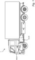
- Fig. 1 is an exemplary embodiment of the present disclosure, comprising a side view of a vehicle 1, in the form of a truck, according to an example.
- the disclosure may relate to any vehicle, such as a car, bus, industrial vehicle, boat, ship, etc., wherein motive power may be derived from an internal combustion engine.
- the vehicle 1 comprises an internal combustion engine system 10.
- the internal combustion engine system may generally herein refer to the ICE system 10.
- the vehicle 1 may also comprise a controller 90.
- the controller is here part of a control system.
- the controller 90 may be part of the ECU of the vehicle 1.
- the controller 90 comprises a processing circuitry 91 configured to control the ICE system 10, as described herein.
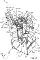
- Fig. 2 shows an example of an ICE system 10.
- the Fig. 2 ICE system 10 may be used in the vehicle 1 of Fig. 1 .
- the ICE system 10 will hereinafter be described in relation to Fig. 2 and Figs. 4A to 4D .
- the ICE system 10 is here a spark-ignition ICE system.
- the ICE system 10 comprises a two-stroke ICE 20 operable on a gaseous fuel 50 or a liquid fuel 50.
- a gaseous fuel is a hydrogen-based fuel.
- a liquid fuel is an NH3-based fuel.
- Other examples of liquid fuels are LNG, LPG, petrol, and the like.
- the two-stroke ICE 20 is operable on a gaseous fuel in the form of a hydrogen-based fuel.
- the combustion in such hydrogen ICE system 10 is based on a combustion of air and hydrogen, as is commonly known in the art. While the combustion of hydrogen with oxygen may only produce water as its only product in a pure combustion process between hydrogen and oxygen, a hydrogen ICE system 10 based on combustion of air and hydrogen generally produce water, heat and NOx, as is commonly known in the art.
- hydrogen can be combusted in an internal combustion engine over a wide range of fuel-air mixtures.
- a hydrogen ICE system 10 may be operated to produce very low emissions during certain conditions.
- the hydrogen ICE system 10 may operate based on hydrogen liquid or hydrogen gas.
- the hydrogen ICE system 10 as described herein contributes to a leaner operation of the ICE 20, which is favorable from a NOx emission perspective.
- the ICE 20 comprises a first cylinder 30 and a second cylinder 40.
- the first cylinder 30 comprises a first cylinder wall 30a and a first cylinder head 30b.
- the first cylinder wall may be part of a cylinder liner.
- the second cylinder 40 comprises a second cylinder wall 40a and a second cylinder head 40b.
- the second cylinder wall may be part of a corresponding cylinder liner.
- the first and second cylinders 30, 40 are here a pair of first and second cylinders 30, 40.
- the first and second cylinders 30, 40 are here a pair of neighboring first and second cylinders 30, 40.
- neighboring generally means that the cylinders are arranged next to each other, i.e. adjacent to each other within the ICE system, so as to allow for forming a pair of cylinders operating according to the two-stroke operation.
- the first and second cylinders 30, 40 are arranged next to each other in the ICE 20. This may have a positive impact on the volumetric efficiency of the ICE system 10.
- first and second cylinders may in some ICE systems be arranged slightly distanced from each other as long as the cylinders work as a pair of cylinders, i.e. the cylinders are connected to the same crank shaft and separated with a 180 crank angle degrees, as further described herein.
- the ICE 20 may comprise any even number of cylinders.
- the ICE 20 may comprise four, six, or eight cylinders.
- the description herein is for an ICE system 10 having a pair of cylinders 30, 40.
- the ICE system 10 further comprises a crank shaft 27, a set of connecting rods, 28, 29 and a crankcase 65.
- the crankcase 65 is configured to accommodate the crank shaft 27 and the connecting rods 28, 29.
- Each one of the connecting rods 28, 29 is operatively connected to a corresponding piston, as further described below.
- the ICE system 20 may also comprise an oil sump 62 and a splash plate for the oil 68. These components are conventional parts of an ICE, and not further described herein.
- the first cylinder 30 is configured to accommodate a reciprocating first piston 31.
- the reciprocating first piston 31 is operable between a bottom dead center, BDC, and a top dead center, TDC.
- the first piston 31 is arranged to reciprocate in the first cylinder 30 between the BDC ( Fig. 4D ) and the TDC ( Fig. 4A )).
- the first piston 31 is in the TDC position at -360°, 0° and 360° CAD.
- the first piston 31 is via a connection rod 28 connected to the crank shaft 27, which is in line with a conventional internal combustion engine.
- the first piston 31 may generally comprise a suitable number of piston rings.
- the first piston 31 comprises one or more compression rings and oil control rings.
- the number of piston rings and type of piston rings are selected based on the fuel of the ICE system 10.
- the piston rings are arranged at a top end 33 of the first piston 31.
- the reciprocating first piston 31 further at least partly defines a first combustion chamber 32 with the top end 33 of the first piston 31.
- the combustion chamber 32 is arranged at the end portion, i.e. the first cylinder head 30b, of the first cylinder 30 so that an upper surface of the top end 33 defines a lower side of the first combustion chamber 32.
- the first cylinder 30 further comprises an ignition source 34.
- the ignition source 34 is arranged in the first combustion chamber 32.
- the ignition source 34 is arranged in the first cylinder 30 and at a location facing the combustion chamber 32.
- the ignition source 34 is arranged at an upper end of the cylinder 30, as illustrated in Fig. 2 .
- the ignition source 34 is arranged at the cylinder head 30b of the first cylinder 30.
- Other arrangements of the ignition source are also conceivable.
- the ignition source 34 is configured to ignite the hydrogen gas supplied via the fuel arrangement, as described herein.
- the ignition source is a spark-plug 17.
- a spark plug is a device for delivering electric current from an ignition system to the combustion chamber of a spark-ignition engine to ignite the compressed fuel/air mixture by an electric spark, while containing combustion pressure within the engine.
- the first cylinder 30 of the ICE 20 comprises at least one intake port 35 arranged at a top end 36 of the first cylinder 30 and in fluid communication with the combustion chamber 32.
- the top end 36 is here an integral part of the cylinder head 30b.
- the flow of combustible gas through the at least one intake port 35 is controllable by an intake control valve 37.
- the combustible gas may generally contain a mix of air and port injected hydrogen gas (the gaseous fuel).
- the intake control valve 37 is arranged to open and close a fluid passage of the intake port 35, thus controlling the flow of fluid to the combustion chamber 32.
- first cylinder 30 of the ICE 20 comprises an exhaust port 38 arranged distal from the top end 36 of the first cylinder 30, such that the at least one intake port 35 and the exhaust port 38 are located at different positions and separated by the piston top end 33 when the first piston 31 is in its top dead center.
- the first cylinder 30 comprises a first exhaust port 38.
- the first exhaust port 38 is configured to exhaust combusted gas from the first cylinder 30.
- the first exhaust port 38 is arranged distal from the top end 33 of the first cylinder 30.
- the intake port 35 and the exhaust port 38 are located at different positions and separated by the top end 33 when the first piston 31 is in its TDC.
- distal means that the exhaust port 38 is arranged spaced apart from the top end 33 in a direction Z of the cylinder 30 corresponding to an axial direction of the piston 31.
- the top end 33 is thus considered to be a proximal part of the first cylinder 30.
- the first piston 31 is arranged in the first cylinder 30 for reciprocal movement along a central axis ZA1, here extending in the direction Z.
- the axial direction of the piston 31 corresponds to the direction Z.
- the central axis ZA1 is thus arranged in parallel to the direction Z.
- the first exhaust port 38 is arranged axially distal from the top end 33 of the first cylinder 30 in the axial direction of the first cylinder 30 and the first piston 31, here corresponding to the direction Z.
- the exhaust port 38 is arranged at a lower to mid part 39 of the first cylinder 30.
- the cylinder liner when the first cylinder 30 comprises the first cylinder liner, the cylinder liner here also comprises the exhaust port 38 located at a lower to mid part 39 of the cylinder liner.
- the exhaust port 38 is generally arranged distal from the top end 33 of the first cylinder 30 and positioned in the cylinder wall 30a of the cylinder liner of the first cylinder 30.
- the second cylinder 40 is configured to accommodate a reciprocating second piston 41.
- the reciprocating second piston 41 is operable between a bottom dead center, BDC, and a top dead center, TDC.
- the second piston 41 is arranged to reciprocate in the second cylinder 40 between the BDC ( Fig. 4A ) and the TDC ( Fig. 4D ).
- the second piston 41 is in the TDC position at -360°, 0° and 360° CAD.
- the second piston 41 is via a connection rod 29 connected to the crank shaft 27, which is in line with a conventional internal combustion engine.
- the second piston 41 may generally comprise a suitable number of piston rings.
- the second piston 41 comprises one or more compression rings and oil control rings.
- the number of piston rings and type of piston rings are selected based on the fuel of the ICE system 10.
- the piston rings are arranged at a top end 43 of the second piston 41.
- the reciprocating second piston 41 further at least partly defines a second combustion chamber 42 with a top end 43 of the second piston 41.
- the combustion chamber 42 is arranged at end portion, i.e. the second cylinder head 40b, of the second cylinder 40 so that an upper surface of the top end 43 defines a lower side of the second combustion chamber 42.
- Each one of the piston top ends may have a flat top or the piston top ends may be slightly dished so as to avoid hotspots.
- the second cylinder 40 further comprises a corresponding ignition source 44 arranged in the second combustion chamber 42.
- the ignition source 44 is arranged in the second cylinder 40 and at a location facing the combustion chamber 42.
- the ignition source 44 is arranged at an upper end of the combustion cylinder 40, as illustrated in Fig. 2 .
- the ignition source 44 is arranged at the cylinder head 40b of the second cylinder 40.
- Other arrangements of the ignition source are also conceivable.
- Each one of the ignition sources 34, 44 is here a spark plug.
- the ignition source may also be a glow plug.
- each cylinder there is a corresponding spark plug arranged to ignite a mix of fuel and oxygen in the cylinder.
- the hydrogen fuel is generally compressed to a certain level.
- the compressed air-fuel mixture is thus ignited by the spark plug.
- the second cylinder 40 of the ICE 20 comprises at least one corresponding intake port 45 arranged at a top end 46 of the second cylinder 40 and in fluid communication with the second combustion chamber 42.
- the top end 46 is here an integral part of the cylinder head 40b.
- the flow of combustible gas through the at least one corresponding intake port 45 is controllable by a corresponding intake control valve 47.
- the combustible gas may generally contain a mix of air and port injected hydrogen gas (the gaseous fuel).
- the intake control valve 47 is arranged to open and close a fluid passage of the intake port 45, thus controlling the flow of fluid to the combustion chamber 42.
- the second cylinder 40 of the ICE 20 comprises a corresponding exhaust port 48 arranged distal from the top end 46 of the second cylinder 40, such that the at least one corresponding intake port 45 and the corresponding exhaust port 48 are located at different positions and separated by the piston top end 43 when the corresponding second piston 41 is in its top dead center.
- the corresponding exhaust port 48 is configured to exhaust combusted gas from the second cylinder 40.
- the corresponding exhaust port 48 is arranged distal from the top end 43 of the second cylinder 40.
- the intake port 45 and the exhaust port 48 are located at different positions and separated by the top end 43 when the second piston 41 is in its TDC.
- distal means that the exhaust port 48 is arranged spaced apart from the top end 43 in the direction Z of the second cylinder 40 corresponding to an axial direction of the second piston 41.
- the top end 43 is thus considered to be a proximal part of the second cylinder 40.
- the second piston 41 is arranged in the second cylinder 40 for reciprocal movement along a central axis ZA2, here extending in the direction Z.
- the axial direction of the second piston 41 corresponds to the direction Z.
- the central axis ZA2 is thus arranged in parallel to the direction Z.
- the second exhaust port 48 is arranged axially distal from the top end 43 of the second cylinder 40 in the axial direction of the second cylinder 40 and the second piston 41, here corresponding to the direction Z.
- the exhaust port 48 is arranged at a lower to mid part 49 of the second cylinder 40.
- the exhaust port 48 is arranged at a lower to mid part 49 of the second cylinder 40 as seen along the central axis ZA2.
- first central axis ZA1 of the first piston 31 is arranged parallel to the second central axis ZA2 of the second piston 41.
- the pistons may also be arranged in a slightly different configuration where the first central axis ZA1 of the first piston 31 is arranged non-parallel to the second central axis ZA2 of the second piston 41, at least as long as the first and second cylinders are arranged separated from each other with a crank angle of 180 degrees.
- the cylinder liner comprises the corresponding exhaust port 48 located at a lower to mid part 49 of the cylinder liner.
- the corresponding exhaust port 48 is generally arranged distal from the top end 43 of the second cylinder 40 and positioned in the cylinder wall 40a of the cylinder liner of the second cylinder 40.
- the pair of neighboring first and second cylinders 30, 40 are arranged separated from each other with a crank angle of 180 degrees (180 CAD).
- 180 CAD 180 degrees
- the cylinders 20, 30 are separated from each other so to provide a 180 degrees combustion phasing separation.
- the cylinders 30, 40 can be arranged in the ICE system 10 to provide a 180 degrees cycle separation irrespectively of the ICE and cylinder arrangement/configuration.
- the respective intake ports 35, 45 and exhaust ports 38. 48 are in each cylinder 30, 40 located at different positions and separated by the respective piston top end 33, 43 when the respective piston is in its TDC. Accordingly, by the provision of arranging the respective intake port 35, 45 and exhaust port 38, 48 of the cylinders 30, 40 at different positions along the direction Z (i.e. along the axial directions of the pistons and cylinders), the corresponding piston will provide for a blocking effect between the intake and exhaust ports when the corresponding piston is in its TDC, so that the hot part of the cylinder (exhaust port and cylinder wall/liner) will be entirely separated from the combustible gas (air).
- the blocking effect is at least schematically illustrated in Fig. 2 , and also in Figs. 4A and 4D .
- the configuration of the intake and exhaust ports enables a length-scavenging ICE system that separates the hot exhaust end of each cylinder from the cold intake end where the combustibles are present. Therefore the knock risk may be reduced during operation of the ICE system 10.
- this also allows for a reversed scavenging of the corresponding combustion chamber with the controllable intake valves in the cylinder head and the exhaust ports at the cylinder wall/liner (e.g. in the lower part of cylinder wall). In other words, there are no exhaust valves in the cylinder head as compared to more conventional ICE systems.
- the ICE system 10 is configured to provide a forced induction in the top of the cylinders, an ignition source for igniting the fuel in each combustion chamber 32, 42, while further being configured to expel the exhaust gases through respective exhaust port 28, 38 in the lower to mid parts of the respective cylinder, e.g. lower parts of the walls 30a, 40a of the cylinder liners.
- the ICE system 10 comprises an air intake duct 22.
- the air intake duct 22 is a manifold which is arranged and configured to feed intake air to the cylinders, in this example the first and second cylinders 30, 40.
- the air intake duct 22 comprises a positive displacement device 23, as illustrated in Fig. 2 .
- the positive displacement device 23 is configured to receive and feed intake air 51 to the at least one pair of neighboring cylinders 30, 40.
- the air intake duct 22 comprises an intake tract 24 and a plenum 25.
- the air intake tract 24 is arranged upstream the positive displacement device 23.
- the plenum 25 is arranged downstream the positive displacement device 23.
- the positive displacement device 23 is also arranged in the air intake duct 22 to separate the upstream intake tract 24 from the downstream plenum 25 of the air intake duct 22.
- the plenum 25 may in some examples be an integral part of the cylinder heads of the cylinders. Hence, at least parts of the air intake duct may be integral parts of the cylinder heads of the cylinders.
- the positive displacement device 23 is configured to fluidly seal against back flow from the combustion chamber(s) 32, 42. Furthermore, the positive displacement device 23 is configured to exhaust its (complete) internal displacement for each revolution.
- the positive displacement device 23 is here a positive displacement pump.
- the positive displacement pump is configured to displace gas from an upstream position to a downstream position of the air intake duct 22 thereof by trapping a fixed amount of air and forcing that trapped amount of air from the upstream position to the downstream position.
- the positive displacement device 23 is a rotary roots type blower having a pair of rotary members 23a, 23b provided with meshing lobes.
- Other configurations of the positive displacement device may also be readily appreciated.
- the positive displacement device 23 is here a variable positive displacement device configured to be operated in a variable manner.
- the use of a variable driven positive displacement device allows for a higher flexibility of the air intake duct forming the air intake system of the ICE system 10.
- the use of a variable driven positive displacement device also contributes to improve the overall function of the ICE system 10.
- Positive displacement devices may generally operate with flow and pressure as independent variables. This means that if pressure increases and speed remains constant, the flow rate is largely unaffected.
- a variable positive displacement device, such as a pump is a device that converts mechanical energy to hydraulic (fluid) energy. The displacement can be varied while the pump is running.
- the positive displacement device may be driven variably for the high flexibility and improved functionality of the ICE system.
- the positive displacement device 23 may be electrically driven, hydraulically driven, etc.
- An electrified positive displacement device may also improve turbo transients by boosting with scavenging that may also drive the turbine in the turbo.
- Such configuration of the ICE system may allow for reduced pressure before the displacement pump and/or after the turbo compressor reducing compressor work instantly.
- the upstream intake tract 24 is here an integral part of the air intake duct 22.
- the intake duct 24 is by way of example provided in the form of a cylindrical shaped housing having an inner volume.
- the plenum 25 is also generally an integral part of the air intake duct 22.
- the downstream plenum 25 is in fluid communication with each one of the first and second cylinders 30, 40.
- the downstream plenum 25 is in fluid communication with each one of the first and second cylinders 30, 40 via respective intake ports 35, 45.
- the downstream plenum 25 is provided in the form of a so-called Siamese-shaped design.
- Siamese-shaped design has a first inlet conduit 25a and a set of two outlet conduits 25b, 25c, as schematically illustrated in Fig. 2 .
- the diameter and length of the inlet and outlet conduits may vary depending on the type of ICE system 10, and the plenum 25 in Fig. 2 is only schematically illustrated.
- the plenum 25 comprises an air inlet 25d in fluid communication with the positive displacement device 23 and a plurality of outlets 25e, 25f configured to be in fluid communication with the intake ports 35, 45 of the first and second cylinders 30, 40, respectively.
- the first inlet conduit 25a has the air inlet and the outlet conduits 25b, 25c have the corresponding outlets.
- the plenum 25 is defined by the conduit arrangement between the intake ports 35, 45 of the first and second cylinders 30, 40 and the positive displacement device 23, as depicted in e.g. Fig. 2 .
- the plenum 25 may also be provided in other ways, e.g. by a single large inner volume defined by a common conduit.
- the internal volume of the plenum should generally be selected to provide an efficient backfire protection, and may thus benefit from being minimized in volume in view of the other volumes of the other components.
- the plenum 25 in combination with the arrangement and configuration of the positive displacement device 23 provides for an improved air supply system for supplying air to the cylinders 30, 40.
- the positive displacement device 23 provides for an essentially fluid-tight seal in the air intake duct 22, it will be a continuous flow of air through the positive displacement device 23 thanks to the configuration of the cylinders 30, 40 with a 180 CAD separation, since the pair of cylinders 30, 40 interact with respect to the intake event.
- the positive displacement device 25 is arranged to eliminate, or at least reduce, the risk of having pressure pulses transferred backwards from the combustion chambers 30, 40 to the upstream intake tract 24 of the air intake duct 22.
- the intake ports 35, 45 are mechanically isolated from the intake tract 24.
- the positive displacement device 23 is thus arranged to seal the cylinders 30, 40 and the downstream plenum 25 from the upstream intake tract 24 of the air intake duct 22 (intake manifold) in case of backfire.
- the positive displacement device 23 can still provide an even flow by alternating feed to the cylinder pair 30, 40.
- the proposed ICE system provides for suppressing the tendency for knock and/or self-ignition of the fuel, such as a gaseous fuel, e.g. hydrogen-based fuel.
- a gaseous fuel e.g. hydrogen-based fuel.
- This is e.g. provided by the combination of having a separate intake plenum 23 for each pair of cylinders 30, 40 with the 180 degrees combustion phasing separation, and where the intake duct 22 has a close coupled positive displacement device 23 for each pair of cylinders 30, 40.
- the positive displacement device 25 close to the cylinders, the internal volume of the plenum 25 can be minimized, thus providing for an even more efficient backfire protection.
- the ICE system 20 here comprises a fuel injector arrangement 26, as illustrated in fig. 2 .
- the fuel injector arrangement 26 is arranged in the plenum 25 of the air intake duct 22 so as to provide a fuel injection upstream the intake ports 35, 45 of the cylinders 30, 40. In this manner, there is provided an improved injection of fuel into the combustion chambers 32, 42 of the ICE 20.
- the fuel injector arrangement 26 comprises at least one fuel injector configured inject fuel.
- the fuel injector arrangement 26 comprises a set of two fuel injector, 26a, 26b.
- the outlet conduit 25b comprises a first fuel injector 26a and the outlet conduit 25c comprises the second fuel injector 26b.
- the ICE system 10 is configured to provide port injection of the gaseous fuel 50 upstream respective intake port 35, 45.
- the use of a port injection allows for providing a homogenous mixture which enables an improved knock and auto-ignition control and contribute to reduce the emissions.
- the fuel injector arrangement 26 is operable / controllable in response to a fuel injection event such that fuel injection is injected to one or more of the corresponding intake ports 35, 45 such that pressure pulses are generated in the plenum 25 and subsequently travel into the corresponding combustion chambers 32, 42.
- a fuel injection event such that fuel injection is injected to one or more of the corresponding intake ports 35, 45 such that pressure pulses are generated in the plenum 25 and subsequently travel into the corresponding combustion chambers 32, 42.
- the ICE system 10 is configured to provide a scavenging effect by the injection timing in the respective intake port 35, 45.
- the fuel injector arrangement 26 is operable / controllable to provide a sequential injection of fuel to the cylinders 30, 40 so as to allow for an active cylinder scavenging during a latter part of a corresponding intake stroke of a corresponding cylinder of the cylinders 30, 40.
- a sequential injection enables active cylinder scavenging (emptying of exhaust) during latter part of the intake stroke and creates a final pressure pulse (from the injected fuel) that increases the trapped mass in the cylinder after any exhaust port and intake valve closures. This may also contribute to a fuel-free plenum and/or intake port after the intake valve closure.
- the generated pressure pulse increases the scavenging effect.
- sequential injection can be tuned for different speeds and valve timings.
- the pressure pulse will also travel backwards in the downstream plenum 25.
- the pressure pulse will be reflected in the sister cylinder intake valve that is closed. Thereafter, the pressure pulse travels back to the still open intake valve and enters the cylinder with the open valve and complete the cylinder filling, thus also contributing to the complete trapped mass.
- the fuel injectors 26a, 26b of the fuel injector arrangement 26 may be arranged in each one of the combustion chambers of the cylinders.
- the ICE system 10 in Fig. 2 is here provided with a number of two intake valves 37 for the first cylinder 30 and a number of two intake control valve 47 for the second cylinder 40.
- each one of the cylinder heads 30b, 40b comprises a number of at least two intake control valves.
- each one of the cylinder heads 30b, 40b of the first and second cylinders 30, 40 may have a plurality of intake control valves.
- each one of the cylinder heads may have a number of four intake control valves.
- Such configuration provides for an even more improved air supply system for supplying air to each one of the cylinders.
- a configuration with an ICE system having four intake control valves for each cylinder is particularly beneficial for two-stroke operated ICE systems operable on a hydrogen-based fuel because it has a shorter intake period than a four stroke ICE system.
- an ICE system 10 comprising the arrangement of the positive displacement device 23 in combination with the arrangement of four intake valves in each cylinder enables an even more improved volumetric efficiency, at least in comparison with conventional ICE system, such as a four-stroke ICE system.
- the intake control valves 37, 47 are configured to provide variable valve actuation.
- the variable valve actuation can be provided by a hydraulic system, electronic system or pneumatic system.
- the intake control valves 37, 47 may also be conventional intake control valves, such as a camshaft-based system, as is commonly used in diesel ICE systems.
- the intake control valves are conventional camshaft actuated valves.
- Such camshaft actuated valves may also include variable valve actuation depending on arrangement and configuration of the valves.
- the ICE system 10 comprises an inlet control valve actuation assembly 63 for actuating the at least one inlet control valve 37 and the corresponding inlet control valve 47.
- the inlet valve actuation assembly 63 is adapted to actuate the inlet control valves 37, 47 in accordance with one or more lift modes during the combustion cycle of the ICE system, which will also be further described in relation to Figs. 4A to 4D .
- each one of the exhaust ports 38, 48 is arranged in fluid communication with an exhaust duct 61 arranged to transport exhaust gas away from each one of the cylinders.
- Fig. 3 is another example of the ICE system 10.
- the ICE system 10 here comprises the features and components of the ICE system 10 as described in relation to Fig. 2 and Figs. 4A to 4D.
- the ICE system 10 illustrated in Fig. 3 differs from that shown in Fig. 2 in that the ICE system 10 also comprises a turbocharger arrangement 70.
- the turbocharger arrangement 70 comprises a turbocharger turbine 71 operatively connected to a turbocharger compressor 72, wherein the turbocharger compressor 72 is arranged in an air intake conduit 73 in fluid communication with the air intake duct 22.
- the turbocharger turbine 71 is arranged in the exhaust duct 61 so as to drive the turbocharger compressor 72.
- the turbine 71 is configured to convert engine exhaust gas into mechanical energy to drive the compressor 72.
- the turbocharger turbine 71 may be a conventional turbine for an ICE system 10. Alternatively, the turbocharger turbine 71 may be a variable geometry turbine in fluid communication with the cylinders.
- the ICE system 10 further comprises an exhaust gas recirculation, EGR, system 80 comprising an EGR conduit 81 arranged to connect the exhaust duct 61 and the air intake duct 22 so as to permit recirculation of exhaust gas through the cylinders during operation of the ICE 20.
- EGR exhaust gas recirculation
- the EGR system 80 here further comprises a corresponding positive displacement device 82.
- the positive displacement device 82 is disposed in the EGR conduit 81.
- the positive displacement device 82 is generally of the same type as the device 23, but may also be provided in other ways.
- the positive displacement device 82 is by way of example a roots blower.
- the EGR conduit 81 connects to the air intake conduit 73 at a position 84 downstream the turbocharger compressor 72 and further connects to the exhaust duct 61 at a position 85 upstream the turbocharger turbine 71.
- the ICE system 10 may also comprise an air cooler 67, such as charge air cooler (CAC).
- CAC charge air cooler
- the CAC 67 is arranged in the air intake conduit 73. More specifically, the CAC 67 is arranged in the air intake conduit 73 between the turbocharger compressor 72 and the air intake duct 72, as seen in a direction of flow from the compressor 72 to the air intake duct 22.
- the air intake duct of Fig. 2 and/or Fig. 3 may have its own inlet for receiving fresh air from the outside and/or be configured to receive air from the air intake conduit 73.
- the positive displacement device 23 can work in several ways working in conjunction with the turbo mounted upstream:
- the positive displacement device 23 just spins to move the air volume past the rotors. In this instance, the positive displacement device consumes little energy since no compression is taking place. The part of blocking of the intake duct 22 from the upstream intake tract 24 is then also functioning (per design).
- the positive displacement device 23 can spin faster and support in getting the boost pressure up, thereby increasing the response of the ICE 20.
- Transient operation is generally challenging for H2 ICE system 10 with a traditional boosting setup since a transient normally result in reduced air/fuel ratio which in turn give a knock tendency or NOx creation. By controlling the air during the transient with additional boost, this issue may be eliminated, or at least reduced to a great extent.
- the turbo is not sufficient for the boosting the positive displacement device 23 can support with additional boosting for improved control of air/ fuel ratio, cylinder scavenging etc., i.e. combustion control.
- the ICE system 10 further comprises the controller 90 configured to collectively control the positive displacement device 23 and the intake valves 37, 47 so as to control flow of gas to the respective combustion chambers 32, 42.
- the controller 90 is configured to terminate fuel injection during an intake phase and before an intake valve closure, whereby the remaining part of the intake phase comprises emptying the plenum 25 of fuel and subsequently introducing fresh air to the plenum 25 by operating the positive displacement device 23.
- each one of the first and second cylinders 30, 40 has three primary events. These events are compression event, combustion and work event, and exhaust and intake event.
- the compression event occurs when a corresponding piston is at an upper half of the corresponding cylinder when it travels from BDC to TDC.
- the combustion and work event occurs when a corresponding piston is at an upper half of the corresponding cylinder when it travels from TDC to BDC.
- the exhaust and intake event generally occurs when a corresponding piston is at a lower half of the corresponding cylinder.
- the exhaust and intake event occurs when a corresponding piston is at a lower half of the cylinder and is travelling towards its BDC, across its BDC and/or when the corresponding piston is at a lower half of the cylinder and is travelling towards its TDC.
- the exhaust and intake event may occur in different regions of the cylinders, and can be slightly divided, but the exhaust and intake event will generally occur at the same time.
- the ICE system provides the scavenging effect, i.e. fresh intake gas pushes the residual exhaust out the exhaust port.
- the piston 31, 41 of one of the cylinders 30, 40 may generally perform the compression phase (or event) during about 270 - 0 CAD, followed by the combustion and work phase (event) during 0 - 90 CAD at an upper half of the corresponding cylinder when the piston travels from TDC to BDC, while the other piston of the other cylinder performs the exhaust and intake phase (event) at a lower half of the other cylinder during 90 to 270 CAD. It may also be noted that there is generally an overlap between the end of the combustion and work phase (event) and the start of the exhaust and intake phase (event).
- the intake control valve 37 of the first cylinder 30 is operable in correlation with the movement of the first piston 31 and the intake control valve 47 of the second cylinder 40 is operable in correlation with the movement of the second piston 41.
- the fluid communication between the respective combustion chambers 32, 42 and the plenum 25 is selectively open and closed during a crank shaft revolution of the ICE 20.
- such configuration of the ICE system 10 in combination with the positive displacement device 23 in the air intake duct 22 allows for reducing risk of backfire.
- the inlet control valve 37 and the corresponding inlet control valve 47 are controlled and actuated by the inlet control valve actuation assembly 63.
- the inlet control valve actuation assembly 63 may comprise an electric actuator (not shown) adapted to actuate the inlet control valve(s) in at least two lift modes, i.e. between an open mode and a closed mode.
- cylinders 30, 40 are separated from each other with a crank angle of 180 degrees.
- Such arrangement and configuration of the ICE system 20 allows for 180 degrees combustion phasing separation.
- the effect of the control of the intake ports by the intake valves in combination with the 180 degrees combustion phasing separation can be exemplified by the illustrations in Figs. 4A and 4D :
- the first intake port 35 of the first cylinder 30 is closed by the inlet control valve 37 to close the fluid communication between the first combustion chamber 32 and the plenum 25 when the corresponding intake port 45 of the second cylinder 40 is open by the inlet control valve 47 to provide a fluid communication between the second combustion chamber 42 and the plenum 25.
- the first piston 31 is positioned in its TDC. In this position, an ignition event of the first cylinder 30 is about to start, or has just been started. The inlet control valve 37 is thus closed.
- the second piston 41 is at its BDC and the corresponding inlet control valve 47 of the second cylinder 40 is fully opened.
- the second cylinder 40 and the second piston 41 are here illustrated in a position corresponding to the exhaust and intake event, i.e. fresh intake gas from the intake port 45 enters the second cylinder 40 and pushes the residual exhaust out from the exhaust port 48.
- This simultaneous operation of the first and second pistons 31, 41 can be performed due to the 180 crank angel degrees separation between the cylinders 30, 40, here also providing the 180 degrees combustion phasing separation.
- the first cylinder 30 and the first piston 31 perform the combustion and work phase, in which the first piston 31 travels from its TDC to its BDC.
- the inlet control valve 37 is closed.
- the second piston 41 in the second cylinder 40 travels from its BDC to its TDC, while performing its intake phase so as to receive fresh air from the corresponding intake port 45.
- the corresponding inlet control valve 47 is partly opened, as illustrated in Fig. 4B .
- This simultaneous operation of the first and second pistons 31, 41 can be performed due to the 180 crank angel degrees separation between the cylinders 30, 40, here also providing the 180 degrees combustion phasing separation.
- the first cylinder 30 and the first piston 31 are illustrated at the end of the combustion and work phase, in which the first piston 31 approaches its BDC.
- the inlet control valve 37 is controlled to move from its closed position to an opened position.
- the inlet control valve 37 is illustrated in a partly opened position.
- the second piston 41 approaches its TDC while the corresponding inlet control valve 47 is set to its closed position.
- the second cylinder 40 and the second piston 41 perform the compression phase so as to compress the received fresh air.
- This simultaneous operation of the first and second pistons 31, 41 can be performed due to the 180 crank angel degrees separation between the cylinders 30, 40, here also providing the 180 degrees combustion phasing separation.
- the first piston 31 is at its BDC and the corresponding inlet control valve 37 of the first cylinder 30 is fully opened.
- the first cylinder 30 and the first piston 31 are here in a position corresponding to the exhaust and intake event, i.e. fresh intake gas from the intake port 35 enters the first cylinder 30 and pushes the residual exhaust out from the exhaust port 38.
- the second piston 41 is positioned in its TDC. In this position, an ignition event of the second cylinder 40 is about to start, or has just been started. The corresponding inlet control valve 47 is thus closed.
- This simultaneous operation of the first and second pistons 31, 41 can be performed due to the 180 crank angel degrees separation between the cylinders 30, 40, here also providing the 180 degrees combustion phasing separation.
- the inlet control valve 37 at the first intake port 35 of the first cylinder 30 is open to provide a fluid communication between the first combustion chamber 32 and the plenum 25 when the corresponding intake port 45 of the second cylinder 40 is closed by the intake control valve 47 to close the fluid communication between the second combustion chamber 42 and the plenum 25.
- the ICE system 10 is configured to operate the intake valves 37, 47 of the first and second cylinders 30, 40 such that the intake valves 37, 47 of the cylinders 30, 40 are completely closed when the respective piston is halfway up in the cylinder, which may further reduce the risk of a backfire.
- the ICE system 10 is operable to expand the combustible gas during a longer time period in the combustion chambers 30, 40 in comparison to the duration of the compression phase. In this manner, there is provided a built-in Miller or Atkinson cycle function that increases efficiency.
- the two-stroke cycle of the ICE system 10 provides for twice as many work cycles as a conventional four-stroke ICE per revolution, the ICE system 10 allows for operating in a lean condition where it is not possible to get as much power per work cycle as a conventional diesel ICE. I.e. while hydrogen gas and other gases need to be run lean for emission purposes (NOx control), the two-stroke cycle allows for creating twice as many work cycles at the same ICE rpm.
- the ICE system 10 may perform the following method:
- a step S 10 when a piston is travelling down from TDC to BDC in one of the cylinders during expansion of the combustibles and a corresponding exhaust port is uncovered, the effective work stroke is ended, and the gases are exhausted through the exhaust port.
- the intake valve(s) of one of the cylinder opens and the cylinder is purged by incoming air fed by the aforementioned boosting system (e.g. by the turbocharger arrangement 70 and the positive displacement device 23). At this stage there is no fuel present in the boost mass or the cylinder.
- step S30 the piston reaches BDC.
- step S40 the piston starts to move up towards its TDC and the piston eventually covers the exhaust port again.
- the fuel injector arrangement is operated to inject e.g. hydrogen fuel.
- the hydrogen fuel is injected into the intake port, creating the pressure pulse from the injected hydrogen fuel.
- the ICE system 10 is operated to start injecting hydrogen gas into the air stream in the plenum 25, thus feeding air and hydrogen into the cylinder.
- the injection starts after the intake valve has opened just after the initial scavenging (cylinder purge) and ends before the intake valve closes which provides an essentially intake tract free of combustible gas.
- Initial scavenging of the cylinder is the time between IVO and start of hydrogen gas injection.
- step S50 the piston continues to travel up (about halfway) through the stroke and the intake valves closes.
- step S60 the piston travels to just before TDC, TDC or just after TDC (i.e. close to TDC).
- step S70 the ignition source (e.g. a spark plug) ignites the homogenous air/hydrogen mix in the cylinder(s).
- the ignition source e.g. a spark plug
- step S80 the piston is forced down in the work stroke (expansion).
- step S90 the cycle repeats from above steps S10 to S80.
- the operation of purging, scavenging and subsequent fuel injection operation, creating a boost pulse, as well as the ending of fuel injection where hydrogen (H2)/air mixture is pushed into the cylinder allows for emptying the plenum 25, while the positive displacement device 23 is operated to push in fresh air in the plenum 25.
- the arrangement and configuration of the ICE system 10 provides for avoiding, or at least reducing the risk of having hydrogen mixture in the plenum 25, hence, reducing the risk for backfire.
- the intake valves are opened all at the same time, a flow effect in the whole cross section area of the cylinder can be obtained so that the cylinder is filled homogenously from top to bottom, driving out the exhaust gases so that low mixing between the fresh charge air and the warm exhaust combustibles is obtained. This may be useful so as to reduce the mixture temperature and residuals in preparation of the mixture.
- the intake valves are then completely closed when the piston is halfway up in the cylinder which reduces the risk of a backfire.
- the combustion chambers can be designed in several different manners and may be any one of a flat, hemispherical, or pent roof design with only intake valves. It may be beneficial to cover a large area of the combustion chamber with valves so that the cylinder filling can be made in an efficient manner.
- All moving parts in the ICE 20 may generally be lubricated by means of conventional pressure lubrication. Other options are also possible.
- the positive displacement device 23 and the plenum 25 of the air intake duct 22 are generally considered to be the cold components and may be made from an aluminum alloy.
- the air intake duct 22 may typically be fastened to the cylinder heads that may be warmer, which is made of cast iron or steel. This may minimize the risk of hydrogen embrittlement since no gas containing hydrogen comes into contact with any iron or steel that is colder than 150 degrees C, which is the threshold when hydrogen embrittlement is considered to occur.
- the ICE system 10 can be cooled in several different ways.
- the ICE system 10 comprises a controlled low temperature coolant circuit for temperature control of the CAC (Compressed Air Cooler) and/or the EGR cooler.
- the condensation level of the returned water from the combustibles (H2 produce H2O when combusted) is controlled.
- the ICE system 10 may comprise water injection system.
- the water injection system can be arranged and configured to inject water in the intake port(s), directly into the cylinder, or prior to the intake positive displacement device 23.
- the condensed water from the exhaust can be used for water injection. If it is injected prior to the positive displacement device, there is a benefit of mixing and evaporation/ cooling in the roots blower.
- the water injection as a temperature reduction medium for the boost air after the positive displacement device is an advantage in examples where the positive displacement device is used for compression work for additional boosting.
- the ICE system 10 may not be restricted to a system with one single pair of cylinders 30, 40, but can also be implemented in an ICE system comprising four cylinders, six cylinders etc. Hence, the ICE system 10 may have a minimum of two cylinders, but multiples of two cylinders may likewise be possible.
- each arrangement of a pair of neighboring cylinders has a corresponding air intake duct with a corresponding positive displacement device.
- a four-cylinders ICE will have two positive displacement devices and a six-cylinder ICE will have three positive displacement devices.
- Such ICE system may also use a positive displacement device with a plurality of separated sections, wherein each section is provided to cooperated with a given pair of cylinders.
- the flow of fluid (air) to each pair of cylinders should be separated from each other.
- the cylinder pairs can be arranged spaced-apart so as to allow for ignition of fuel for three cylinders at once (flat crank) or arranged evenly offset from each other for an evenly spread firing order. In this way, it becomes possible to charge one cylinder in the pair at the time without creating unwanted pulsation since one cylinder is in its intake stroke while the other one is in its work stroke.
- Example 1 A spark-ignition internal combustion engine, ICE, system 10 for a vehicle, comprising: a two-stroke ICE 20 operable on a gaseous fuel or a liquid fuel 50, the ICE having at least a pair of first and second cylinders 30, 40 with corresponding first and second cylinder walls 30a, 40a, the first cylinder accommodating a reciprocating first piston 31 operable between a bottom dead center and a top dead center, and further at least partly defining a first combustion chamber 32 with a top end 33 of the first piston, wherein the first cylinder further comprises an ignition source 34 arranged in the first combustion chamber, at least one intake port 35 arranged at a top end 36 of the first cylinder and in fluid communication with the combustion chamber, wherein the flow of combustible gas through the at least one intake port is controllable by an intake control valve 37, and further an exhaust port 38 arranged distal from the top end of the first cylinder, such that the at least one intake port and the exhaust port are located at different positions and separated by the piston top end when
- Example 2 The ICE system of example 1, wherein the ICE system comprises a fuel injector arrangement 26 arranged in the downstream plenum of the air intake duct so as to provide a fuel injection upstream the intake ports of the first and second cylinders.
- Example 3 The ICE system of example 2, wherein the fuel injector arrangement is controllable in response to a fuel injection event such that fuel injection is injected to the intake port and the corresponding intake port such that pressure pulses are generated in the plenum and subsequently travel into the corresponding combustion chambers.
- Example 4 The ICE system according to any one of examples 2 and 3, wherein the fuel injector arrangement is controllable to provide a sequential injection of fuel to the first and second cylinders so as to allow for active cylinder scavenging during a latter part of a corresponding intake stroke of a corresponding cylinder of the first and second cylinders.
- Example 5 The ICE system according to any one of the preceding examples, wherein the intake control valve of the first cylinder is controllable in correlation with the movement of the first piston and the intake control valve of the second cylinder is controllable in correlation with the movement of the second piston such that fluid communication between the respective combustion chambers and the downstream plenum being selectively open and closed during a crank shaft revolution of the ICE.
- Example 6 The ICE system according to any one of the preceding examples, wherein the plenum comprises an air inlet in fluid communication with the positive displacement device and a plurality of outlets configured to be in fluid communication with the intake ports of the first and second cylinders.
- Example 7 The ICE system according to any one of the preceding examples, wherein the intake control valves are configured to provide variable valve actuation.
- Example 8 The ICE system according to any one of the preceding examples, wherein the positive displacement device is a variable positive displacement device configured to be operated in a variable manner.
- Example 9 The ICE system according to any one of the preceding examples, wherein the exhaust ports are arranged in fluid communication with an exhaust duct 61 arranged to transport exhaust gas away from the cylinders.
- Example 10 The ICE system according to any one of the preceding examples, further comprising a turbocharger arrangement 70 having a turbocharger turbine 71 operatively connected to a turbocharger compressor 72, wherein the turbocharger compressor is arranged in an air intake conduit 73 to the air intake duct, wherein the turbocharger turbine is arranged in the exhaust duct so as to drive the turbocharger compressor.
- a turbocharger arrangement 70 having a turbocharger turbine 71 operatively connected to a turbocharger compressor 72, wherein the turbocharger compressor is arranged in an air intake conduit 73 to the air intake duct, wherein the turbocharger turbine is arranged in the exhaust duct so as to drive the turbocharger compressor.
- Example 11 The ICE system according to any one of the preceding examples, further comprising an exhaust gas recirculation EGR system 80 comprising an EGR conduit 81 arranged to connect the exhaust duct 61 and the air intake duct 22 so as to permit recirculation of exhaust gas through the cylinders during operation of the ICE.
- an exhaust gas recirculation EGR system 80 comprising an EGR conduit 81 arranged to connect the exhaust duct 61 and the air intake duct 22 so as to permit recirculation of exhaust gas through the cylinders during operation of the ICE.
- Example 12 The ICE system according to example 11, wherein the EGR system further comprises a corresponding positive displacement device 82.
- Example 13 The ICE system according to example 12 or example 13, wherein the EGR conduit connects to the air intake conduit at a position 84 downstream the turbocharger compressor and further connects to the exhaust duct at a position 85 upstream the turbocharger turbine.
- Example 14 The ICE system according to any one of the preceding examples, wherein the ICE system is a hydrogen ICE system configured to operate on a gaseous fuel containing a hydrogen-based gaseous fuel.
- Example 15 The ICE system according to any one of the preceding examples, wherein the ICE system is configured to collectively control the positive displacement device and the intake valves so as to control flow of gas to the combustion chambers.
- Example 16 The ICE system according to example 15, wherein the ICE system is configured to be controllable to terminate fuel injection during an intake phase and before an intake valve closure, whereby the remaining part of the intake phase comprises emptying the plenum of fuel and subsequently introducing fresh air to the plenum by operating the positive displacement device.
- Example 17 The ICE system according to any one of the preceding examples, wherein the ICE system comprises a multiple set of pair of cylinders having corresponding air intake ducts with corresponding positive displacement devices.
- Example 18 A vehicle comprising an internal combustion engine system according to any one of the examples 1 to 17.
- upstream and downstream refer to the relative direction with respect to fluid flow in a fluid pathway.
- upstream refers to the direction from which the fluid flows
- downstream refers to the direction to which the fluid flows.
- longitudinal refers to a direction at least extending between axial ends of a particular component, typically along the arrangement or components thereof in the direction of the longest extension of the arrangement and/or components.
- vertical refers to the axial direction.
- Relative terms such as “below” or “above” or “upper” or “lower” or “horizontal” or “vertical” may be used herein to describe a relationship of one element to another element as illustrated in the Figures. It will be understood that these terms and those discussed above are intended to encompass different orientations of the device in addition to the orientation depicted in the Figures. It will be understood that when an element is referred to as being “connected” or “coupled” to another element, it can be directly connected or coupled to the other element, or intervening elements may be present. In contrast, when an element is referred to as being “directly connected” or “directly coupled” to another element, there are no intervening elements present.
Landscapes
- Engineering & Computer Science (AREA)
- Chemical & Material Sciences (AREA)
- Combustion & Propulsion (AREA)
- Mechanical Engineering (AREA)
- General Engineering & Computer Science (AREA)
- Output Control And Ontrol Of Special Type Engine (AREA)
Abstract
Description
- The disclosure relates generally to an internal combustion engine system and a method for operating an internal combustion engine system. The disclosure can be applied to heavy-duty vehicles, such as trucks, buses, and construction equipment, among other vehicle types. Although the disclosure may be described with respect to a truck, the disclosure is not restricted to any particular vehicle. The internal combustion engine system may e.g. be applicable for other types of vehicles propelled by means of an internal combustion engine such as cars and other light-weight and light-duty vehicles etc. Further, the internal combustion engine of the internal combustion engine system may typically be an internal combustion engine operable on a hydrogen-based fuel.
- To reduce negative climate effects there is an increasing interest in reducing the use of fossil fuels. By way of example, reduction of exhaust gases, increasing engine efficiency, i.e. reduced fuel consumption, and lower noise level from the engines are some of the criteria that have become more important aspects when designing and selecting a suitable internal combustion engine (ICE) system and its engine component. Furthermore, in the field of heavy-duty vehicles, such as trucks, there are a number of prevailing environmental regulations that set specific requirements on the vehicles, e.g. restrictions relating to maximum allowable amount of exhaust gas pollution.
- One possibility is to use hydrogen gas, produced in a fossil-free way, as fuel in internal combustion engines instead of using e.g. fossil-based diesel. The huge amount of conventional, already existing, diesel engines cannot operate properly if simply just fed with hydrogen instead of diesel; these engines must be adapted before being capable of using hydrogen fuel. However, to make such adaptation of existing diesel engines economically feasible, it is necessary that the adaptations are not too complex and costly.
- According to a first aspect of the disclosure, there is provided a spark-ignition internal combustion engine, ICE, system for a vehicle. The ICE system comprises a two-stroke ICE operable on a gaseous fuel or a liquid fuel. The ICE has at least a pair of first and second cylinders with corresponding first and second cylinder walls. The first cylinder accommodates a reciprocating first piston operable between a bottom dead center and a top dead center, and further at least partly defining a first combustion chamber with a top end of the first piston, wherein the first cylinder further comprises an ignition source arranged in the first combustion chamber, at least one intake port arranged at a top end of the first cylinder and in fluid communication with the combustion chamber, wherein the flow of combustible gas through the at least one intake port is controllable by an intake control valve, and further an exhaust port arranged distal from the top end of the first cylinder, such that the at least one intake port and the exhaust port are located at different positions and separated by the piston top end when the first piston is in its top dead center, the second cylinder accommodates a reciprocating second piston operable between a bottom dead center and a top dead center, and further at least partly defining a second combustion chamber with a top end of the second piston, wherein the second cylinder further comprises a corresponding ignition source arranged in the second combustion chamber, at least one corresponding intake port arranged at a top end of the second cylinder and in fluid communication with the second combustion chamber, wherein the flow of combustible gas through the at least one corresponding intake port is controllable by a corresponding intake control valve, and further a corresponding exhaust port arranged distal from the top end of the second cylinder, such that the at least one corresponding intake port and the corresponding exhaust port are located at different positions and separated by the piston top end when the second piston is in its top dead center, the pair of first and second cylinders being arranged separated from each other with a crank angle of 180 degrees, and an air intake duct comprising a positive displacement device configured to receive and feed intake air to the at least one pair of cylinders, the positive displacement device further being arranged in the air intake duct to separate an upstream intake tract from a downstream plenum of the air intake duct, and configured to permit the downstream plenum to be in fluid communication with each one of the first and second cylinders of the at least one pair of cylinders.
- The first aspect of the disclosure may seek to provide an improved two-stroke ICE system controllable to prevent transfer of pressure pulses into the induction system so as to avoid, or at least reduce backfiring. A technical benefit may include an increased versatility in the control of the combustion chamber temperature. Moreover, the proposed ICE system allows for reducing time to ignition with decreased risk of having backfiring into the induction system of the ICE system.
- By the arrangement of the positive displacement device in the air intake duct, the displacement device is arranged to eliminate, or at least reduce, the risk of having pressure pulses transferred backwards from the combustion chambers to the upstream intake tract of the air intake duct.
- As such, the intake ports are mechanically isolated from the intake tract. The positive displacement device is thus arranged to seal the cylinders and the downstream intake plenum from the upstream intake tract of the air intake duct (intake manifold) in case of backfire.
- Also, by the arrangement and configuration of the displacement device in the air intake duct, the displacement device can still provide an even flow by the alternating feed to the cylinder pair.
- Moreover, the proposed ICE system provides for suppressing the tendency for knock and/or self-ignition of the fuel, such as a gaseous fuel, e.g. hydrogen-based fuel.
- By the provision of arranging the respective intake port and exhaust port of the cylinders at different positions, the corresponding piston will provide for a blocking effect between the intake and exhaust ports when the piston is in its top dead center, so that the hot part of the cylinder (exhaust port and cylinder wall/liner) will be entirely separated from the combustible gas (generally corresponding to an air/fuel mixture).
- As such, the proposed ICE system enables a length-scavenging system that separates the hot exhaust end of the cylinder from the cold intake end where the combustibles are present. Therefore, the knock risk may be drastically reduced with the proposed ICE system.
- By the provision of having the pair of first and second cylinders arranged separated from each other with a crank angle of 180 degrees, the two cylinders can provide a 180 degrees cycle separation irrespectively of the ICE and cylinder arrangement/configuration.
- To sum up, the proposed ICE system thus provides separate intake plenum for each pair of cylinders with a 180 degrees combustion phasing separation, where the intake duct has a close coupled positive displacement device for each pair of cylinders. It should be noted that the proposed ICE system may not be restricted to a system with one single pair of cylinders, but can also be implemented in four cylinders, six cylinders etc. Hence, the proposed ICE system may have a minimum of two cylinders, but multiples of two cylinders may be possible.
- Accordingly, there is provided an ICE system having forced induction in the top of the cylinders, an ignition source for igniting the fuel, while being configured to expel the exhaust gases through exhaust ports in the lower to mid parts of the cylinder, e.g. lower parts of the cylinder walls/liners.
- In addition, the proposed two-stroke ICE, favorably operable on hydrogen, or any other gaseous fuel, provides for increasing the BMEP potential due to twice the firing frequency. In particular, the two-stroke cycle enable the ICE to operate at a higher lambda with a maintained power density, as compared to four stroke ICEs.
- A "two-stroke operation" or "two-stroke mode" refers to a cycle of the internal combustion engine, in which the piston moves two strokes (up and down movements) between the TDC and the BDC during only one crank shaft revolution so as to complete a full work cycle. In general, the operation of the internal combustion engine when operated in a general two-stroke operation corresponds to a repetitive engine operation every crank shaft revolution.
- In some examples, including in at least one preferred example, optionally the pair of first and second cylinders may be arranged separated from each other with a crank angle of 180 degrees, so as to provide a 180 degrees combustion phasing separation.
- In some examples, including in at least one preferred example, optionally the fuel may be a gaseous fuel. One example of a gaseous fuel is a hydrogen-based fuel.
- In some examples, including in at least one preferred example, optionally the fuel is a liquid fuel. One example of a liquid fuel is an NH3-based fuel.
- In some examples, including in at least one preferred example, optionally the ignition source may be any one of a spark plug and a glow plug.
- In some examples, including in at least one preferred example, optionally each one of the intake control valve and the corresponding intake control valve may be arranged to open and close a fluid passage of the respective intake port, thus controlling the flow of fluid to the respective combustion chamber.
- In some examples, including in at least one preferred example, optionally the ICE system may comprise a fuel injector arrangement arranged in the downstream plenum of the air intake duct so as to provide a fuel injection upstream the intake ports of the first and second cylinders. A technical benefit may include an improved injection of fuel into the combustion chamber(s) of the ICE. Hereby, the ICE system is configured to provide port injection of the gaseous fuel or the liquid fuel.
- The use of a port injection allows for providing a homogenous mixture which enables an improved knock and auto-ignition control and also contributes to reduce the emissions.
- Alternatively, the fuel injector arrangement may be arranged in each one of the combustion chambers of the first and second cylinders, respectively.
- In some examples, including in at least one preferred example, optionally the fuel injector arrangement may be controllable to inject fuel to the intake port and the corresponding intake port such that pressure pulses are generated in the downstream plenum and subsequently travel into the corresponding combustion chambers. A technical benefit may include an improved scavenging effect. As such, the ICE system is configured to provide a scavenging effect by the injection timing in the intake port(s). The fuel injector arrangement may generally be operable in response to a predetermined fuel injection event.
- In some examples, including in at least one preferred example, optionally the fuel injector arrangement may be controllable to provide a sequential injection of fuel to the first and second cylinders so as to allow for an active cylinder scavenging during a latter part of a corresponding intake stroke of a corresponding cylinder of the first and second cylinders. Put it differently, a sequential injection may enable active cylinder scavenging (emptying of exhaust) during latter part of the intake stroke, thus creating a final pressure pulse (from the injected fuel) that increases the trapped mass in the cylinder after any exhaust port and intake valve closures. Further, the generated pressure pulse may increase the scavenging effect.
- In some examples, including in at least one preferred example, optionally the intake control valve of the first cylinder may be controllable in correlation with the movement of the first piston and the intake control valve of the second cylinder may be controllable in correlation with the movement of the second piston such that fluid communication between the respective combustion chambers and the plenum being selectively open and closed during a crank shaft revolution of the ICE. A technical benefit may include to further reduce the risk of backfire.
- In some examples, including in at least one preferred example, optionally the plenum may comprise an air inlet in fluid communication with the positive displacement device and a plurality of outlets configured to be in fluid communication with the intake ports of the first and second cylinders. A technical benefit may include an improved air supply system for supplying air to the cylinders. By way of example, the plenum is a Siamese-shaped design.
- In some examples, each one of the cylinder heads of the first and second cylinders may have a plurality of intake control valves. The number of intake control valves for each cylinder can generally be any practical number and may generally be selected based on cylinder type and ICE type. By way of example, each one of the cylinder heads may have a number of four intake control valves. A technical benefit may include an even more improved air supply system for supplying air to the cylinders. A configuration with an ICE system having four intake control valves for each cylinder may be particularly beneficial for two-stroke operated ICE systems that may typically have a shorter intake period that four stroke ICE system. A configuration with an ICE system having four intake control valves for each cylinder allows for increasing the air intake rate into the combustion chamber of the cylinder. In addition, it may improve the scavenging phase expelling (pushing out) the exhaust in a uniform, pressure-wave, manner.
- In some examples, including in at least one preferred example, optionally the intake control valves may be configured to provide variable valve actuation. A technical benefit may include an improved control of the air supply system for supplying air to the cylinders during operation of the ICE system. Variable valve actuation may also allow for tuning the phasing (valve timing) for a more optimum pulse capture and efficiency in synchronization with the fuel injection and the corresponding pulse in the plenum.
- In some examples, including in at least one preferred example, optionally the positive displacement device may be a variable positive displacement device configured to be operated in a variable manner. A technical benefit may include an improved control of the flow and/or pressure of air to the cylinders during operation of the ICE system. Moreover, a variable driven positive displacement device allows for a higher flexibility of the air intake system of the ICE system and also an improved function of the ICE system on a general level.
- In some examples, including in at least one preferred example, optionally the pair of first and second cylinders are arranged as a pair of neighboring cylinders. In this manner, the volumetric efficiency of the ICE system may further be improved.
- In some examples, including in at least one preferred example, optionally the ICE system may further comprise additional pairs of cylinders with corresponding air intakes duct and positive displacement devices.
- In some examples, including in at least one preferred example, optionally the exhaust ports may be arranged in fluid communication with an exhaust duct arranged to transport exhaust gas away from the cylinders.
- In some examples, including in at least one preferred example, optionally the ICE system may further comprise a turbocharger arrangement having a turbocharger turbine operatively connected to a turbocharger compressor, wherein the turbocharger compressor is arranged in an air intake conduit to the air intake duct, and wherein the turbocharger turbine is arranged in the exhaust duct so as to drive the turbocharger compressor.
- In some examples, including in at least one preferred example, optionally the ICE system may further comprise an exhaust gas recirculation EGR system comprising an EGR conduit arranged to connect the exhaust duct and the air intake duct so as to permit recirculation of exhaust gas through the cylinders during operation of the ICE.
- In some examples, including in at least one preferred example, optionally the EGR system may further comprise a corresponding positive displacement device.
- In some examples, including in at least one preferred example, optionally the EGR conduit may connect to the air intake conduit at a position downstream the turbocharger compressor and further connects to the exhaust duct at a position upstream the turbocharger turbine.
- In some examples, including in at least one preferred example, optionally the ICE system may be a hydrogen ICE system configured to operate on a gaseous fuel containing a hydrogen-based gaseous fuel. Accordingly, the proposed ICE system may be particularly useful for hydrogen ICE systems. Hydrogen-based fuel may generally have a high auto-ignition temperature; however, low ignition energy may only be needed if a spark (or glowing surface or particle) is present. The low ignition energy may, however, pose some challenges on the ICE, e.g. it may be difficult to use a cylinder head where the hot exhaust ports/valves are located in the same combustion chamber as the intake ports/valves or in the vicinity of the compressed air/ fuel mixture prior to ignition. A technical benefit of the proposed ICE system for use with a hydrogen-based fuel may include a more reliable and robust hydrogen ICE system.
- In some examples, including in at least one preferred example, optionally the ICE system may be configured to collectively control the positive displacement device and the intake valves so as to control flow of gas to the combustion chambers. The positive displacement device and the intake valves may be controllable by a controller, such as an electronic control unit comprising a processing circuitry. In addition, or alternatively, the positive displacement device may be controllable by a controller and the intake valves may be controllable by one or more camshafts and/or the intake valves may be controllable by one or more corresponding actuators of the intake valves.
- In some examples, including in at least one preferred example, optionally the ICE system may be configured to be controllable to terminate fuel injection during an intake phase and before an intake valve closure, whereby the remaining part of the intake phase comprises emptying the plenum of fuel and subsequently introducing fresh air to the plenum by operating the positive displacement device. By way of example, the ICE system may comprise a controller configured to terminate fuel injection during an intake phase and before an intake valve closure, whereby the remaining part of the intake phase comprises emptying the plenum of fuel and subsequently introducing fresh air to the plenum by operating the positive displacement device.
- In some examples, including in at least one preferred example, optionally the ICE system may comprise a multiple set of pair of cylinders having corresponding air intake ducts with corresponding positive displacement devices.
- According to a second aspect of the disclosure, there is provided a vehicle comprising an internal combustion engine system according to the first aspect and/or according to any one of the examples of the first aspect.
- The disclosed aspects, examples (including any preferred examples), and/or accompanying claims may be suitably combined with each other as would be apparent to anyone of ordinary skill in the art. Additional features and advantages are disclosed in the following description, claims, and drawings, and in part will be readily apparent therefrom to those skilled in the art or recognized by practicing the disclosure as described herein.
- Examples are described in more detail below with reference to the appended drawings.
-
Fig. 1 is an exemplary embodiment of the present disclosure, comprising a side view of a vehicle, in the form of a truck, according to an example. -
Fig. 2 shows an internal combustion engine system, according to an example. -
Fig. 3 shows an internal combustion engine system, according to an example. -
Figs. 4A to 4D shows an example of a combustion cycle of the internal combustion engine system inFig. 2 and/orFig. 3 . - The detailed description set forth below provides information and examples of the disclosed technology with sufficient detail to enable those skilled in the art to practice the disclosure.
- For an internal combustion engine system, it may be desired to control the risk of backfiring, i.e. a condition when a flame escapes from the combustion chamber of the cylinder and travels upstream into the air intake duct. It has also been observed that managing self-ignition and backfiring in a reliable manner is particularly useful for hydrogen ICE system.
- The disclosure may seek to provide an improved two-stroke ICE system controllable to prevent pressure pulses into the induction system so as to avoid, or at least reduce backfiring. A technical benefit may include an increased versatility in the control of the combustion chamber temperature. Moreover, the two-stroke ICE system allows for reducing time to ignition with decreased risk of having backfiring into the induction system of the ICE system.
-
Fig. 1 is an exemplary embodiment of the present disclosure, comprising a side view of avehicle 1, in the form of a truck, according to an example. - Whilst the shown embodiment illustrates a truck, the disclosure may relate to any vehicle, such as a car, bus, industrial vehicle, boat, ship, etc., wherein motive power may be derived from an internal combustion engine.
- The
vehicle 1 comprises an internalcombustion engine system 10. The internal combustion engine system may generally herein refer to theICE system 10. Moreover, thevehicle 1 may also comprise a controller 90. The controller is here part of a control system. The controller 90 may be part of the ECU of thevehicle 1. The controller 90 comprises a processing circuitry 91 configured to control theICE system 10, as described herein. -
Fig. 2 shows an example of anICE system 10. Purely by way of example, theFig. 2 ICE system 10 may be used in thevehicle 1 ofFig. 1 . TheICE system 10 will hereinafter be described in relation toFig. 2 andFigs. 4A to 4D . - The
ICE system 10 is here a spark-ignition ICE system. TheICE system 10 comprises a two-stroke ICE 20 operable on agaseous fuel 50 or aliquid fuel 50. One example of a gaseous fuel is a hydrogen-based fuel. One example of a liquid fuel is an NH3-based fuel. Other examples of liquid fuels are LNG, LPG, petrol, and the like. - In this example, the two-
stroke ICE 20 is operable on a gaseous fuel in the form of a hydrogen-based fuel. The combustion in suchhydrogen ICE system 10 is based on a combustion of air and hydrogen, as is commonly known in the art. While the combustion of hydrogen with oxygen may only produce water as its only product in a pure combustion process between hydrogen and oxygen, ahydrogen ICE system 10 based on combustion of air and hydrogen generally produce water, heat and NOx, as is commonly known in the art. In addition, hydrogen can be combusted in an internal combustion engine over a wide range of fuel-air mixtures. Ahydrogen ICE system 10 may be operated to produce very low emissions during certain conditions. Thehydrogen ICE system 10 may operate based on hydrogen liquid or hydrogen gas. Thehydrogen ICE system 10 as described herein contributes to a leaner operation of theICE 20, which is favorable from a NOx emission perspective. - As depicted in
Fig. 2 , and further inFigs. 4A to 4D , theICE 20 comprises afirst cylinder 30 and asecond cylinder 40. Thefirst cylinder 30 comprises afirst cylinder wall 30a and afirst cylinder head 30b. The first cylinder wall may be part of a cylinder liner. In a similar vein, thesecond cylinder 40 comprises asecond cylinder wall 40a and asecond cylinder head 40b. The second cylinder wall may be part of a corresponding cylinder liner. - The first and
second cylinders second cylinders second cylinders second cylinders second cylinders ICE 20. This may have a positive impact on the volumetric efficiency of theICE system 10. However, it should be noted that the first and second cylinders may in some ICE systems be arranged slightly distanced from each other as long as the cylinders work as a pair of cylinders, i.e. the cylinders are connected to the same crank shaft and separated with a 180 crank angle degrees, as further described herein. - It should be noted that the
ICE 20 may comprise any even number of cylinders. For example, theICE 20 may comprise four, six, or eight cylinders. For ease of reference, however, the description herein is for anICE system 10 having a pair ofcylinders - As illustrated in
Fig. 2 , theICE system 10 further comprises acrank shaft 27, a set of connecting rods, 28, 29 and acrankcase 65. Thecrankcase 65 is configured to accommodate thecrank shaft 27 and the connectingrods rods - The
ICE system 20 may also comprise anoil sump 62 and a splash plate for theoil 68. These components are conventional parts of an ICE, and not further described herein. - The
first cylinder 30 is configured to accommodate a reciprocatingfirst piston 31. The reciprocatingfirst piston 31 is operable between a bottom dead center, BDC, and a top dead center, TDC. - More specifically, as may be gleaned from
Fig. 4A in combination withFig. 4D , thefirst piston 31 is arranged to reciprocate in thefirst cylinder 30 between the BDC (Fig. 4D ) and the TDC (Fig. 4A )). With reference toFig. 4D , thefirst piston 31 is in the TDC position at -360°, 0° and 360° CAD. Thefirst piston 31 is via aconnection rod 28 connected to thecrank shaft 27, which is in line with a conventional internal combustion engine. - The
first piston 31 may generally comprise a suitable number of piston rings. By way of example, thefirst piston 31 comprises one or more compression rings and oil control rings. The number of piston rings and type of piston rings are selected based on the fuel of theICE system 10. In this example, the piston rings are arranged at atop end 33 of thefirst piston 31. - The reciprocating
first piston 31 further at least partly defines afirst combustion chamber 32 with thetop end 33 of thefirst piston 31. Thecombustion chamber 32 is arranged at the end portion, i.e. thefirst cylinder head 30b, of thefirst cylinder 30 so that an upper surface of thetop end 33 defines a lower side of thefirst combustion chamber 32. - The
first cylinder 30 further comprises anignition source 34. Theignition source 34 is arranged in thefirst combustion chamber 32. Theignition source 34 is arranged in thefirst cylinder 30 and at a location facing thecombustion chamber 32. By way of example, theignition source 34 is arranged at an upper end of thecylinder 30, as illustrated inFig. 2 . In particular, theignition source 34 is arranged at thecylinder head 30b of thefirst cylinder 30. Other arrangements of the ignition source are also conceivable. - The
ignition source 34 is configured to ignite the hydrogen gas supplied via the fuel arrangement, as described herein. By way of example, the ignition source is a spark-plug 17. A spark plug is a device for delivering electric current from an ignition system to the combustion chamber of a spark-ignition engine to ignite the compressed fuel/air mixture by an electric spark, while containing combustion pressure within the engine. - In addition, the
first cylinder 30 of theICE 20 comprises at least oneintake port 35 arranged at atop end 36 of thefirst cylinder 30 and in fluid communication with thecombustion chamber 32. Thetop end 36 is here an integral part of thecylinder head 30b. - Moreover, the flow of combustible gas through the at least one
intake port 35 is controllable by anintake control valve 37. In this example, the combustible gas may generally contain a mix of air and port injected hydrogen gas (the gaseous fuel). - The
intake control valve 37 is arranged to open and close a fluid passage of theintake port 35, thus controlling the flow of fluid to thecombustion chamber 32. - Further, the
first cylinder 30 of theICE 20 comprises anexhaust port 38 arranged distal from thetop end 36 of thefirst cylinder 30, such that the at least oneintake port 35 and theexhaust port 38 are located at different positions and separated by the pistontop end 33 when thefirst piston 31 is in its top dead center. - More specifically, as illustrated in
Fig. 2 , thefirst cylinder 30 comprises afirst exhaust port 38. Thefirst exhaust port 38 is configured to exhaust combusted gas from thefirst cylinder 30. Thefirst exhaust port 38 is arranged distal from thetop end 33 of thefirst cylinder 30. Hereby, theintake port 35 and theexhaust port 38 are located at different positions and separated by thetop end 33 when thefirst piston 31 is in its TDC. In this context, the term "distal" means that theexhaust port 38 is arranged spaced apart from thetop end 33 in a direction Z of thecylinder 30 corresponding to an axial direction of thepiston 31. Thetop end 33 is thus considered to be a proximal part of thefirst cylinder 30. In other words, thefirst piston 31 is arranged in thefirst cylinder 30 for reciprocal movement along a central axis ZA1, here extending in the direction Z. In other words, in this example, the axial direction of thepiston 31 corresponds to the direction Z. the central axis ZA1 is thus arranged in parallel to the direction Z. Hence, thefirst exhaust port 38 is arranged axially distal from thetop end 33 of thefirst cylinder 30 in the axial direction of thefirst cylinder 30 and thefirst piston 31, here corresponding to the direction Z. - By way of example, the
exhaust port 38 is arranged at a lower tomid part 39 of thefirst cylinder 30. - In some examples, as illustrated in
Fig. 2 , when thefirst cylinder 30 comprises the first cylinder liner, the cylinder liner here also comprises theexhaust port 38 located at a lower tomid part 39 of the cylinder liner. Hence, theexhaust port 38 is generally arranged distal from thetop end 33 of thefirst cylinder 30 and positioned in thecylinder wall 30a of the cylinder liner of thefirst cylinder 30. - The
second cylinder 40 is configured to accommodate a reciprocatingsecond piston 41. The reciprocatingsecond piston 41 is operable between a bottom dead center, BDC, and a top dead center, TDC. - More specifically, as may be gleaned from
Fig. 4A in combination withFig. 4D , thesecond piston 41 is arranged to reciprocate in thesecond cylinder 40 between the BDC (Fig. 4A ) and the TDC (Fig. 4D ). With reference toFig. 4A , thesecond piston 41 is in the TDC position at -360°, 0° and 360° CAD. Thesecond piston 41 is via aconnection rod 29 connected to thecrank shaft 27, which is in line with a conventional internal combustion engine. - The
second piston 41 may generally comprise a suitable number of piston rings. By way of example, thesecond piston 41 comprises one or more compression rings and oil control rings. The number of piston rings and type of piston rings are selected based on the fuel of theICE system 10. In this example, the piston rings are arranged at atop end 43 of thesecond piston 41. - The reciprocating
second piston 41 further at least partly defines asecond combustion chamber 42 with atop end 43 of thesecond piston 41. Thecombustion chamber 42 is arranged at end portion, i.e. thesecond cylinder head 40b, of thesecond cylinder 40 so that an upper surface of thetop end 43 defines a lower side of thesecond combustion chamber 42. - Each one of the piston top ends may have a flat top or the piston top ends may be slightly dished so as to avoid hotspots.
- The
second cylinder 40 further comprises acorresponding ignition source 44 arranged in thesecond combustion chamber 42. Theignition source 44 is arranged in thesecond cylinder 40 and at a location facing thecombustion chamber 42. By way of example, theignition source 44 is arranged at an upper end of thecombustion cylinder 40, as illustrated inFig. 2 . In particular, theignition source 44 is arranged at thecylinder head 40b of thesecond cylinder 40. Other arrangements of the ignition source are also conceivable. - Each one of the ignition sources 34, 44 is here a spark plug. The ignition source may also be a glow plug.
- Accordingly, in each cylinder, there is a corresponding spark plug arranged to ignite a mix of fuel and oxygen in the cylinder. The hydrogen fuel is generally compressed to a certain level. The compressed air-fuel mixture is thus ignited by the spark plug.
- In addition, the
second cylinder 40 of theICE 20 comprises at least onecorresponding intake port 45 arranged at atop end 46 of thesecond cylinder 40 and in fluid communication with thesecond combustion chamber 42. Thetop end 46 is here an integral part of thecylinder head 40b. - Moreover, the flow of combustible gas through the at least one
corresponding intake port 45 is controllable by a correspondingintake control valve 47. In this example, the combustible gas may generally contain a mix of air and port injected hydrogen gas (the gaseous fuel). - The
intake control valve 47 is arranged to open and close a fluid passage of theintake port 45, thus controlling the flow of fluid to thecombustion chamber 42. - Further, the
second cylinder 40 of theICE 20 comprises acorresponding exhaust port 48 arranged distal from thetop end 46 of thesecond cylinder 40, such that the at least onecorresponding intake port 45 and thecorresponding exhaust port 48 are located at different positions and separated by the pistontop end 43 when the correspondingsecond piston 41 is in its top dead center. - In a similar vein to the first cylinder and its exhaust port, the corresponding
exhaust port 48 is configured to exhaust combusted gas from thesecond cylinder 40. The correspondingexhaust port 48 is arranged distal from thetop end 43 of thesecond cylinder 40. Hereby, theintake port 45 and theexhaust port 48 are located at different positions and separated by thetop end 43 when thesecond piston 41 is in its TDC. In this context, the term "distal" means that theexhaust port 48 is arranged spaced apart from thetop end 43 in the direction Z of thesecond cylinder 40 corresponding to an axial direction of thesecond piston 41. Thetop end 43 is thus considered to be a proximal part of thesecond cylinder 40. - More specifically, the
second piston 41 is arranged in thesecond cylinder 40 for reciprocal movement along a central axis ZA2, here extending in the direction Z. In other words, in this example, the axial direction of thesecond piston 41 corresponds to the direction Z. The central axis ZA2 is thus arranged in parallel to the direction Z. Hence, thesecond exhaust port 48 is arranged axially distal from thetop end 43 of thesecond cylinder 40 in the axial direction of thesecond cylinder 40 and thesecond piston 41, here corresponding to the direction Z. - By way of example, the
exhaust port 48 is arranged at a lower to mid part 49 of thesecond cylinder 40. Theexhaust port 48 is arranged at a lower to mid part 49 of thesecond cylinder 40 as seen along the central axis ZA2. - It should be noted that in
Fig. 2 , the first central axis ZA1 of thefirst piston 31 is arranged parallel to the second central axis ZA2 of thesecond piston 41. However, the pistons may also be arranged in a slightly different configuration where the first central axis ZA1 of thefirst piston 31 is arranged non-parallel to the second central axis ZA2 of thesecond piston 41, at least as long as the first and second cylinders are arranged separated from each other with a crank angle of 180 degrees. - In some examples, as illustrated in
Fig. 2 , when thesecond cylinder 40 comprises the second cylinder liner, the cylinder liner comprises thecorresponding exhaust port 48 located at a lower to mid part 49 of the cylinder liner. Hence, the correspondingexhaust port 48 is generally arranged distal from thetop end 43 of thesecond cylinder 40 and positioned in thecylinder wall 40a of the cylinder liner of thesecond cylinder 40. - As illustrated in
Fig. 2 , the pair of neighboring first andsecond cylinders cylinders cylinders ICE system 10 to provide a 180 degrees cycle separation irrespectively of the ICE and cylinder arrangement/configuration. - By arranging the
exhaust ports cylinders respective intake ports exhaust ports 38. 48 are in eachcylinder top end respective intake port exhaust port cylinders Fig. 2 , and also inFigs. 4A and4D . - As such, the configuration of the intake and exhaust ports enables a length-scavenging ICE system that separates the hot exhaust end of each cylinder from the cold intake end where the combustibles are present. Therefore the knock risk may be reduced during operation of the
ICE system 10. In comparison with a two-stroke diesel ICE using multiple cylinders, this also allows for a reversed scavenging of the corresponding combustion chamber with the controllable intake valves in the cylinder head and the exhaust ports at the cylinder wall/liner (e.g. in the lower part of cylinder wall). In other words, there are no exhaust valves in the cylinder head as compared to more conventional ICE systems. - By the combination of the arrangement of the
ignition source exhaust ports ICE system 10 is configured to provide a forced induction in the top of the cylinders, an ignition source for igniting the fuel in eachcombustion chamber respective exhaust port walls - Further, as depicted in
Fig. 2 , theICE system 10 comprises anair intake duct 22. Theair intake duct 22 is a manifold which is arranged and configured to feed intake air to the cylinders, in this example the first andsecond cylinders - The
air intake duct 22 comprises apositive displacement device 23, as illustrated inFig. 2 . Thepositive displacement device 23 is configured to receive andfeed intake air 51 to the at least one pair of neighboringcylinders air intake duct 22 comprises anintake tract 24 and aplenum 25. Theair intake tract 24 is arranged upstream thepositive displacement device 23. Theplenum 25 is arranged downstream thepositive displacement device 23. Thepositive displacement device 23 is also arranged in theair intake duct 22 to separate theupstream intake tract 24 from thedownstream plenum 25 of theair intake duct 22. - It should be noted that the
plenum 25 may in some examples be an integral part of the cylinder heads of the cylinders. Hence, at least parts of the air intake duct may be integral parts of the cylinder heads of the cylinders. - The
positive displacement device 23 is configured to fluidly seal against back flow from the combustion chamber(s) 32, 42. Furthermore, thepositive displacement device 23 is configured to exhaust its (complete) internal displacement for each revolution. - The
positive displacement device 23 is here a positive displacement pump. The positive displacement pump is configured to displace gas from an upstream position to a downstream position of theair intake duct 22 thereof by trapping a fixed amount of air and forcing that trapped amount of air from the upstream position to the downstream position. - By way of example, the
positive displacement device 23 is a rotary roots type blower having a pair ofrotary members - The
positive displacement device 23 is here a variable positive displacement device configured to be operated in a variable manner. The use of a variable driven positive displacement device allows for a higher flexibility of the air intake duct forming the air intake system of theICE system 10. The use of a variable driven positive displacement device also contributes to improve the overall function of theICE system 10. Positive displacement devices may generally operate with flow and pressure as independent variables. This means that if pressure increases and speed remains constant, the flow rate is largely unaffected. A variable positive displacement device, such as a pump, is a device that converts mechanical energy to hydraulic (fluid) energy. The displacement can be varied while the pump is running. The positive displacement device may be driven variably for the high flexibility and improved functionality of the ICE system. - The
positive displacement device 23 may be electrically driven, hydraulically driven, etc. An electrified positive displacement device may also improve turbo transients by boosting with scavenging that may also drive the turbine in the turbo. Such configuration of the ICE system may allow for reduced pressure before the displacement pump and/or after the turbo compressor reducing compressor work instantly. - The
upstream intake tract 24 is here an integral part of theair intake duct 22. Theintake duct 24 is by way of example provided in the form of a cylindrical shaped housing having an inner volume. Theplenum 25 is also generally an integral part of theair intake duct 22. - Also, as illustrated in
Fig. 2 , thedownstream plenum 25 is in fluid communication with each one of the first andsecond cylinders Fig. 2 , thedownstream plenum 25 is in fluid communication with each one of the first andsecond cylinders respective intake ports - In
Fig. 2 , thedownstream plenum 25 is provided in the form of a so-called Siamese-shaped design. Such Siamese-shaped design has afirst inlet conduit 25a and a set of twooutlet conduits Fig. 2 . The diameter and length of the inlet and outlet conduits may vary depending on the type ofICE system 10, and theplenum 25 inFig. 2 is only schematically illustrated. - The
plenum 25 comprises anair inlet 25d in fluid communication with thepositive displacement device 23 and a plurality ofoutlets intake ports second cylinders first inlet conduit 25a has the air inlet and theoutlet conduits - Accordingly, the
plenum 25 is defined by the conduit arrangement between theintake ports second cylinders positive displacement device 23, as depicted in e.g.Fig. 2 . - The
plenum 25 may also be provided in other ways, e.g. by a single large inner volume defined by a common conduit. The internal volume of the plenum should generally be selected to provide an efficient backfire protection, and may thus benefit from being minimized in volume in view of the other volumes of the other components. - The
plenum 25 in combination with the arrangement and configuration of thepositive displacement device 23 provides for an improved air supply system for supplying air to thecylinders - It should be noted that even though the
positive displacement device 23 provides for an essentially fluid-tight seal in theair intake duct 22, it will be a continuous flow of air through thepositive displacement device 23 thanks to the configuration of thecylinders cylinders - By the arrangement of the
positive displacement device 23 in theair intake duct 22, thepositive displacement device 25 is arranged to eliminate, or at least reduce, the risk of having pressure pulses transferred backwards from thecombustion chambers upstream intake tract 24 of theair intake duct 22. - As such, the
intake ports intake tract 24. Thepositive displacement device 23 is thus arranged to seal thecylinders downstream plenum 25 from theupstream intake tract 24 of the air intake duct 22 (intake manifold) in case of backfire. - Also, by the arrangement and configuration of the
positive displacement device 23 in theair intake duct 22, thepositive displacement device 23 can still provide an even flow by alternating feed to thecylinder pair - Moreover, the proposed ICE system provides for suppressing the tendency for knock and/or self-ignition of the fuel, such as a gaseous fuel, e.g. hydrogen-based fuel. This is e.g. provided by the combination of having a
separate intake plenum 23 for each pair ofcylinders intake duct 22 has a close coupledpositive displacement device 23 for each pair ofcylinders positive displacement device 25 close to the cylinders, the internal volume of theplenum 25 can be minimized, thus providing for an even more efficient backfire protection. - The
ICE system 20 here comprises afuel injector arrangement 26, as illustrated infig. 2 . Thefuel injector arrangement 26 is arranged in theplenum 25 of theair intake duct 22 so as to provide a fuel injection upstream theintake ports cylinders combustion chambers ICE 20. - The
fuel injector arrangement 26 comprises at least one fuel injector configured inject fuel. InFig. 2 , thefuel injector arrangement 26 comprises a set of two fuel injector, 26a, 26b. There is generally onefuel injector respective intake port outlet conduit 25b comprises afirst fuel injector 26a and theoutlet conduit 25c comprises thesecond fuel injector 26b. Hereby, theICE system 10 is configured to provide port injection of thegaseous fuel 50 upstreamrespective intake port - The
fuel injector arrangement 26 is operable / controllable in response to a fuel injection event such that fuel injection is injected to one or more of the correspondingintake ports plenum 25 and subsequently travel into the correspondingcombustion chambers ICE system 10 is configured to provide a scavenging effect by the injection timing in therespective intake port - By way of example, the
fuel injector arrangement 26 is operable / controllable to provide a sequential injection of fuel to thecylinders cylinders - Put it differently, a sequential injection enables active cylinder scavenging (emptying of exhaust) during latter part of the intake stroke and creates a final pressure pulse (from the injected fuel) that increases the trapped mass in the cylinder after any exhaust port and intake valve closures. This may also contribute to a fuel-free plenum and/or intake port after the intake valve closure.
- Further, the generated pressure pulse increases the scavenging effect.
- It may be noted that the sequential injection can be tuned for different speeds and valve timings.
- In general, the pressure pulse will also travel backwards in the
downstream plenum 25. For instance, the pressure pulse will be reflected in the sister cylinder intake valve that is closed. Thereafter, the pressure pulse travels back to the still open intake valve and enters the cylinder with the open valve and complete the cylinder filling, thus also contributing to the complete trapped mass. - In some examples, although not illustrated, the
fuel injectors fuel injector arrangement 26 may be arranged in each one of the combustion chambers of the cylinders. - Turning again to the
intake ports intake valves ICE system 10 inFig. 2 is here provided with a number of twointake valves 37 for thefirst cylinder 30 and a number of twointake control valve 47 for thesecond cylinder 40. - Hence, in some examples, each one of the
cylinder heads cylinder heads second cylinders combustion chambers cylinders ICE system 10 comprising the arrangement of thepositive displacement device 23 in combination with the arrangement of four intake valves in each cylinder enables an even more improved volumetric efficiency, at least in comparison with conventional ICE system, such as a four-stroke ICE system. - In
Fig. 2 , theintake control valves intake control valves - In
Fig. 2 , theICE system 10 comprises an inlet controlvalve actuation assembly 63 for actuating the at least oneinlet control valve 37 and the correspondinginlet control valve 47. The inletvalve actuation assembly 63 is adapted to actuate theinlet control valves Figs. 4A to 4D . - As may also be gleaned from
Fig. 2 , each one of theexhaust ports exhaust duct 61 arranged to transport exhaust gas away from each one of the cylinders. -
Fig. 3 is another example of theICE system 10. TheICE system 10 here comprises the features and components of theICE system 10 as described in relation toFig. 2 andFigs. 4A to 4D. TheICE system 10 illustrated inFig. 3 differs from that shown inFig. 2 in that theICE system 10 also comprises aturbocharger arrangement 70. Theturbocharger arrangement 70 comprises aturbocharger turbine 71 operatively connected to aturbocharger compressor 72, wherein theturbocharger compressor 72 is arranged in anair intake conduit 73 in fluid communication with theair intake duct 22. Theturbocharger turbine 71 is arranged in theexhaust duct 61 so as to drive theturbocharger compressor 72. In other words, theturbine 71 is configured to convert engine exhaust gas into mechanical energy to drive thecompressor 72. - The
turbocharger turbine 71 may be a conventional turbine for anICE system 10. Alternatively, theturbocharger turbine 71 may be a variable geometry turbine in fluid communication with the cylinders. - In
Fig. 3 , theICE system 10 further comprises an exhaust gas recirculation, EGR,system 80 comprising anEGR conduit 81 arranged to connect theexhaust duct 61 and theair intake duct 22 so as to permit recirculation of exhaust gas through the cylinders during operation of theICE 20. - The
EGR system 80 here further comprises a correspondingpositive displacement device 82. Thepositive displacement device 82 is disposed in theEGR conduit 81. Thepositive displacement device 82 is generally of the same type as thedevice 23, but may also be provided in other ways. Thepositive displacement device 82 is by way of example a roots blower. - The
EGR conduit 81 connects to theair intake conduit 73 at aposition 84 downstream theturbocharger compressor 72 and further connects to theexhaust duct 61 at aposition 85 upstream theturbocharger turbine 71. - Typically, as illustrated in
Fig. 3 , theICE system 10 may also comprise anair cooler 67, such as charge air cooler (CAC). By way of example, theCAC 67 is arranged in theair intake conduit 73. More specifically, theCAC 67 is arranged in theair intake conduit 73 between theturbocharger compressor 72 and theair intake duct 72, as seen in a direction of flow from thecompressor 72 to theair intake duct 22. - It should be readily appreciated that the air intake duct of
Fig. 2 and/orFig. 3 may have its own inlet for receiving fresh air from the outside and/or be configured to receive air from theair intake conduit 73. - For
ICE systems 10 with aturbocharged arrangement 70 as illustrated inFig. 3 , thepositive displacement device 23 can work in several ways working in conjunction with the turbo mounted upstream: - If the intake air flow is at the desired level the
positive displacement device 23 just spins to move the air volume past the rotors. In this instance, the positive displacement device consumes little energy since no compression is taking place. The part of blocking of theintake duct 22 from theupstream intake tract 24 is then also functioning (per design). - If in a transient state and the turbocharger have not spun up, the
positive displacement device 23 can spin faster and support in getting the boost pressure up, thereby increasing the response of theICE 20. Transient operation is generally challenging forH2 ICE system 10 with a traditional boosting setup since a transient normally result in reduced air/fuel ratio which in turn give a knock tendency or NOx creation. By controlling the air during the transient with additional boost, this issue may be eliminated, or at least reduced to a great extent. - At some operating points, where the turbo is not sufficient for the boosting the
positive displacement device 23 can support with additional boosting for improved control of air/ fuel ratio, cylinder scavenging etc., i.e. combustion control. - Moreover, in the
ICE system 10 described in relation toFig. 2 and/orFig. 3 , theICE system 10 further comprises the controller 90 configured to collectively control thepositive displacement device 23 and theintake valves respective combustion chambers - By way of example, the controller 90 is configured to terminate fuel injection during an intake phase and before an intake valve closure, whereby the remaining part of the intake phase comprises emptying the
plenum 25 of fuel and subsequently introducing fresh air to theplenum 25 by operating thepositive displacement device 23. - In the following, there is an example of a sequence of operating the
ICE system 10 during the two-stroke operation. The sequence of the two-stroke operation is described in conjunction withFigs. 4A to 4D . - In generally, it should be noted that each one of the first and
second cylinders - It should, however, be noted that the exhaust and intake event may occur in different regions of the cylinders, and can be slightly divided, but the exhaust and intake event will generally occur at the same time. During the exhaust and intake event, the ICE system provides the scavenging effect, i.e. fresh intake gas pushes the residual exhaust out the exhaust port.
- In view of the above, the
piston cylinders - More specifically, as schematically illustrated in
Figs. 4A to 4D , theintake control valve 37 of thefirst cylinder 30 is operable in correlation with the movement of thefirst piston 31 and theintake control valve 47 of thesecond cylinder 40 is operable in correlation with the movement of thesecond piston 41. In this manner, the fluid communication between therespective combustion chambers plenum 25 is selectively open and closed during a crank shaft revolution of theICE 20. As mentioned herein, such configuration of theICE system 10 in combination with thepositive displacement device 23 in theair intake duct 22 allows for reducing risk of backfire. - The
inlet control valve 37 and the correspondinginlet control valve 47 are controlled and actuated by the inlet controlvalve actuation assembly 63. Purely by way of example, the inlet controlvalve actuation assembly 63 may comprise an electric actuator (not shown) adapted to actuate the inlet control valve(s) in at least two lift modes, i.e. between an open mode and a closed mode. - In addition, as mentioned above, the
cylinders ICE system 20 allows for 180 degrees combustion phasing separation. The effect of the control of the intake ports by the intake valves in combination with the 180 degrees combustion phasing separation can be exemplified by the illustrations inFigs. 4A and4D : - In
Fig. 4A , thefirst intake port 35 of thefirst cylinder 30 is closed by theinlet control valve 37 to close the fluid communication between thefirst combustion chamber 32 and theplenum 25 when thecorresponding intake port 45 of thesecond cylinder 40 is open by theinlet control valve 47 to provide a fluid communication between thesecond combustion chamber 42 and theplenum 25. InFig. 4A , thefirst piston 31 is positioned in its TDC. In this position, an ignition event of thefirst cylinder 30 is about to start, or has just been started. Theinlet control valve 37 is thus closed. In addition, inFig. 4A , thesecond piston 41 is at its BDC and the correspondinginlet control valve 47 of thesecond cylinder 40 is fully opened. Thesecond cylinder 40 and thesecond piston 41 are here illustrated in a position corresponding to the exhaust and intake event, i.e. fresh intake gas from theintake port 45 enters thesecond cylinder 40 and pushes the residual exhaust out from theexhaust port 48. This simultaneous operation of the first andsecond pistons cylinders - Subsequently, as illustrated in
Fig. 4B , thefirst cylinder 30 and thefirst piston 31 perform the combustion and work phase, in which thefirst piston 31 travels from its TDC to its BDC. In this position, theinlet control valve 37 is closed. In addition, as illustrated inFig. 4B , thesecond piston 41 in thesecond cylinder 40 travels from its BDC to its TDC, while performing its intake phase so as to receive fresh air from the correspondingintake port 45. In this position, the correspondinginlet control valve 47 is partly opened, as illustrated inFig. 4B . This simultaneous operation of the first andsecond pistons cylinders - In
Fig. 4C , thefirst cylinder 30 and thefirst piston 31 are illustrated at the end of the combustion and work phase, in which thefirst piston 31 approaches its BDC. In this position, theinlet control valve 37 is controlled to move from its closed position to an opened position. Hence, inFig. 4C , theinlet control valve 37 is illustrated in a partly opened position. In addition, as illustrated inFig. 4C , thesecond piston 41 approaches its TDC while the correspondinginlet control valve 47 is set to its closed position. At this position, thesecond cylinder 40 and thesecond piston 41 perform the compression phase so as to compress the received fresh air. This simultaneous operation of the first andsecond pistons cylinders - Finally, as illustrated in
Fig. 4D , thefirst piston 31 is at its BDC and the correspondinginlet control valve 37 of thefirst cylinder 30 is fully opened. Thefirst cylinder 30 and thefirst piston 31 are here in a position corresponding to the exhaust and intake event, i.e. fresh intake gas from theintake port 35 enters thefirst cylinder 30 and pushes the residual exhaust out from theexhaust port 38. In addition, thesecond piston 41 is positioned in its TDC. In this position, an ignition event of thesecond cylinder 40 is about to start, or has just been started. The correspondinginlet control valve 47 is thus closed. This simultaneous operation of the first andsecond pistons cylinders - As may also be gleaned from
Fig. 4D , theinlet control valve 37 at thefirst intake port 35 of thefirst cylinder 30 is open to provide a fluid communication between thefirst combustion chamber 32 and theplenum 25 when thecorresponding intake port 45 of thesecond cylinder 40 is closed by theintake control valve 47 to close the fluid communication between thesecond combustion chamber 42 and theplenum 25. - In addition, as may be gleaned from
Figs. 4A to 4D , due to the arrangement of the first andsecond cylinders ICE system 10 is configured to operate theintake valves second cylinders intake valves cylinders - Accordingly, by the configuration of having the first and
second cylinders positive displacement device 23, as illustrated in e.g.Fig. 2 in combination withFigs. 4A to 4D , it becomes possible to reduce the risk of backfire. - Also, although not explicitly shown in
Figs. 4A to 4D , it should be readily appreciated that at injection, after scavenging has started, the injected hydrogen fuel will expand and create a pulse in the intake ports and plenum. This pulse will propagate and add to the scavenging effect and also increase the pressure in the cylinder. However, the pulse is limited from travelling backwards in the air intake duct (air intake system) by thepositive displacement device 23 acting like a check valve and also momentarily adding boost pressure during the pulse. - Moreover, depending on when in time the
intake valves ICE system 10 is operable to expand the combustible gas during a longer time period in thecombustion chambers - Further, since the two-stroke cycle of the
ICE system 10 provides for twice as many work cycles as a conventional four-stroke ICE per revolution, theICE system 10 allows for operating in a lean condition where it is not possible to get as much power per work cycle as a conventional diesel ICE. I.e. while hydrogen gas and other gases need to be run lean for emission purposes (NOx control), the two-stroke cycle allows for creating twice as many work cycles at the same ICE rpm. - In operation of the
ICE system 10, theICE system 10 may perform the following method: - In a
step S 10, when a piston is travelling down from TDC to BDC in one of the cylinders during expansion of the combustibles and a corresponding exhaust port is uncovered, the effective work stroke is ended, and the gases are exhausted through the exhaust port. Subsequently, in a step S20, the intake valve(s) of one of the cylinder opens and the cylinder is purged by incoming air fed by the aforementioned boosting system (e.g. by theturbocharger arrangement 70 and the positive displacement device 23). At this stage there is no fuel present in the boost mass or the cylinder. - Then, in step S30, the piston reaches BDC. Thereafter, in step S40, the piston starts to move up towards its TDC and the piston eventually covers the exhaust port again. At this position, the fuel injector arrangement is operated to inject e.g. hydrogen fuel. The hydrogen fuel is injected into the intake port, creating the pressure pulse from the injected hydrogen fuel. As such, the
ICE system 10 is operated to start injecting hydrogen gas into the air stream in theplenum 25, thus feeding air and hydrogen into the cylinder. The injection starts after the intake valve has opened just after the initial scavenging (cylinder purge) and ends before the intake valve closes which provides an essentially intake tract free of combustible gas. - Initial scavenging of the cylinder (purging) is the time between IVO and start of hydrogen gas injection.
- In step S50, the piston continues to travel up (about halfway) through the stroke and the intake valves closes.
- In step S60, the piston travels to just before TDC, TDC or just after TDC (i.e. close to TDC).
- Subsequently, in step S70, the ignition source (e.g. a spark plug) ignites the homogenous air/hydrogen mix in the cylinder(s).
- Then, in step S80, the piston is forced down in the work stroke (expansion).
- Thereafter, in step S90, the cycle repeats from above steps S10 to S80.
- As should be readily appreciated from the above, the operation of purging, scavenging and subsequent fuel injection operation, creating a boost pulse, as well as the ending of fuel injection where hydrogen (H2)/air mixture is pushed into the cylinder allows for emptying the
plenum 25, while thepositive displacement device 23 is operated to push in fresh air in theplenum 25. In this manner, the arrangement and configuration of theICE system 10 provides for avoiding, or at least reducing the risk of having hydrogen mixture in theplenum 25, hence, reducing the risk for backfire. - It should be noted that if the intake valves are opened all at the same time, a flow effect in the whole cross section area of the cylinder can be obtained so that the cylinder is filled homogenously from top to bottom, driving out the exhaust gases so that low mixing between the fresh charge air and the warm exhaust combustibles is obtained. This may be useful so as to reduce the mixture temperature and residuals in preparation of the mixture. The intake valves are then completely closed when the piston is halfway up in the cylinder which reduces the risk of a backfire.
- It should be noted that the above presentation of the
ICE system 10 should also be regarded as disclosing a method for controlling theICE system 10, for instance using the controller 90. - The combustion chambers can be designed in several different manners and may be any one of a flat, hemispherical, or pent roof design with only intake valves. It may be beneficial to cover a large area of the combustion chamber with valves so that the cylinder filling can be made in an efficient manner.
- All moving parts in the
ICE 20 may generally be lubricated by means of conventional pressure lubrication. Other options are also possible. - The
positive displacement device 23 and theplenum 25 of theair intake duct 22 are generally considered to be the cold components and may be made from an aluminum alloy. Theair intake duct 22 may typically be fastened to the cylinder heads that may be warmer, which is made of cast iron or steel. This may minimize the risk of hydrogen embrittlement since no gas containing hydrogen comes into contact with any iron or steel that is colder than 150 degrees C, which is the threshold when hydrogen embrittlement is considered to occur. - The
ICE system 10 can be cooled in several different ways. By way of example, theICE system 10 comprises a controlled low temperature coolant circuit for temperature control of the CAC (Compressed Air Cooler) and/or the EGR cooler. By this, the condensation level of the returned water from the combustibles (H2 produce H2O when combusted) is controlled. In addition, theICE system 10 may comprise water injection system. The water injection system can be arranged and configured to inject water in the intake port(s), directly into the cylinder, or prior to the intakepositive displacement device 23. Moreover, the condensed water from the exhaust can be used for water injection. If it is injected prior to the positive displacement device, there is a benefit of mixing and evaporation/ cooling in the roots blower. The water injection as a temperature reduction medium for the boost air after the positive displacement device is an advantage in examples where the positive displacement device is used for compression work for additional boosting. - It should be noted that the
ICE system 10 may not be restricted to a system with one single pair ofcylinders ICE system 10 may have a minimum of two cylinders, but multiples of two cylinders may likewise be possible. - In
ICE systems 10 further comprising additional pairs of neighboring cylinders, each arrangement of a pair of neighboring cylinders has a corresponding air intake duct with a corresponding positive displacement device. - In other words, a four-cylinders ICE will have two positive displacement devices and a six-cylinder ICE will have three positive displacement devices. Such ICE system may also use a positive displacement device with a plurality of separated sections, wherein each section is provided to cooperated with a given pair of cylinders. In this arrangement, the flow of fluid (air) to each pair of cylinders should be separated from each other. The cylinder pairs can be arranged spaced-apart so as to allow for ignition of fuel for three cylinders at once (flat crank) or arranged evenly offset from each other for an evenly spread firing order. In this way, it becomes possible to charge one cylinder in the pair at the time without creating unwanted pulsation since one cylinder is in its intake stroke while the other one is in its work stroke.
- Moreover, the present disclosure may be exemplified by any one of the below examples.
- Example 1: A spark-ignition internal combustion engine, ICE, system 10 for a vehicle, comprising: a two-stroke ICE 20 operable on a gaseous fuel or a liquid fuel 50, the ICE having at least a pair of first and second cylinders 30, 40 with corresponding first and second cylinder walls 30a, 40a, the first cylinder accommodating a reciprocating first piston 31 operable between a bottom dead center and a top dead center, and further at least partly defining a first combustion chamber 32 with a top end 33 of the first piston, wherein the first cylinder further comprises an ignition source 34 arranged in the first combustion chamber, at least one intake port 35 arranged at a top end 36 of the first cylinder and in fluid communication with the combustion chamber, wherein the flow of combustible gas through the at least one intake port is controllable by an intake control valve 37, and further an exhaust port 38 arranged distal from the top end of the first cylinder, such that the at least one intake port and the exhaust port are located at different positions and separated by the piston top end when the first piston is in its top dead center, the second cylinder accommodating a reciprocating second piston 41 operable between a bottom dead center and a top dead center, and further at least partly defining a second combustion chamber 42 with a top end 43 of the second piston, wherein the second cylinder further comprises a corresponding ignition source 44 arranged in the second combustion chamber, at least one corresponding intake port 45 arranged at a top end 46 of the second cylinder and in fluid communication with the second combustion chamber, wherein the flow of combustible gas through the at least one corresponding intake port is controllable by a corresponding intake control valve 47, and further a corresponding exhaust port 48 arranged distal from the top end of the second cylinder, such that the at least one corresponding intake port and the corresponding exhaust port are located at different positions and separated by the piston top end when the second piston is in its top dead center, the pair of first and second cylinders being arranged separated from each other with a crank angle of 180 degrees, and an air intake duct 22 comprising a positive displacement device 23 configured to receive and feed intake air to the at least one pair of cylinders, the positive displacement device further being arranged in the air intake duct to separate an upstream intake tract 24 from a downstream plenum 25 of the air intake duct, the downstream plenum being in fluid communication with each one of the first and second cylinders of the at least one pair of cylinders.
- Example 2: The ICE system of example 1, wherein the ICE system comprises a
fuel injector arrangement 26 arranged in the downstream plenum of the air intake duct so as to provide a fuel injection upstream the intake ports of the first and second cylinders. - Example 3: The ICE system of example 2, wherein the fuel injector arrangement is controllable in response to a fuel injection event such that fuel injection is injected to the intake port and the corresponding intake port such that pressure pulses are generated in the plenum and subsequently travel into the corresponding combustion chambers.
- Example 4: The ICE system according to any one of examples 2 and 3, wherein the fuel injector arrangement is controllable to provide a sequential injection of fuel to the first and second cylinders so as to allow for active cylinder scavenging during a latter part of a corresponding intake stroke of a corresponding cylinder of the first and second cylinders.
- Example 5: The ICE system according to any one of the preceding examples, wherein the intake control valve of the first cylinder is controllable in correlation with the movement of the first piston and the intake control valve of the second cylinder is controllable in correlation with the movement of the second piston such that fluid communication between the respective combustion chambers and the downstream plenum being selectively open and closed during a crank shaft revolution of the ICE.
- Example 6: The ICE system according to any one of the preceding examples, wherein the plenum comprises an air inlet in fluid communication with the positive displacement device and a plurality of outlets configured to be in fluid communication with the intake ports of the first and second cylinders.
- Example 7: The ICE system according to any one of the preceding examples, wherein the intake control valves are configured to provide variable valve actuation.
- Example 8: The ICE system according to any one of the preceding examples, wherein the positive displacement device is a variable positive displacement device configured to be operated in a variable manner.
- Example 9: The ICE system according to any one of the preceding examples, wherein the exhaust ports are arranged in fluid communication with an
exhaust duct 61 arranged to transport exhaust gas away from the cylinders. - Example 10: The ICE system according to any one of the preceding examples, further comprising a
turbocharger arrangement 70 having aturbocharger turbine 71 operatively connected to aturbocharger compressor 72, wherein the turbocharger compressor is arranged in anair intake conduit 73 to the air intake duct, wherein the turbocharger turbine is arranged in the exhaust duct so as to drive the turbocharger compressor. - Example 11: The ICE system according to any one of the preceding examples, further comprising an exhaust gas
recirculation EGR system 80 comprising anEGR conduit 81 arranged to connect theexhaust duct 61 and theair intake duct 22 so as to permit recirculation of exhaust gas through the cylinders during operation of the ICE. - Example 12: The ICE system according to example 11, wherein the EGR system further comprises a corresponding
positive displacement device 82. - Example 13: The ICE system according to example 12 or example 13, wherein the EGR conduit connects to the air intake conduit at a
position 84 downstream the turbocharger compressor and further connects to the exhaust duct at aposition 85 upstream the turbocharger turbine. - Example 14: The ICE system according to any one of the preceding examples, wherein the ICE system is a hydrogen ICE system configured to operate on a gaseous fuel containing a hydrogen-based gaseous fuel.
- Example 15: The ICE system according to any one of the preceding examples, wherein the ICE system is configured to collectively control the positive displacement device and the intake valves so as to control flow of gas to the combustion chambers.
- Example 16: The ICE system according to example 15, wherein the ICE system is configured to be controllable to terminate fuel injection during an intake phase and before an intake valve closure, whereby the remaining part of the intake phase comprises emptying the plenum of fuel and subsequently introducing fresh air to the plenum by operating the positive displacement device.
- Example 17: The ICE system according to any one of the preceding examples, wherein the ICE system comprises a multiple set of pair of cylinders having corresponding air intake ducts with corresponding positive displacement devices.
- Example 18: A vehicle comprising an internal combustion engine system according to any one of the examples 1 to 17.
- As used herein, the terms "upstream" and "downstream" refer to the relative direction with respect to fluid flow in a fluid pathway. For example, "upstream" refers to the direction from which the fluid flows, and "downstream" refers to the direction to which the fluid flows.
- Also, the term "longitudinal", "longitudinally", "axially" or "axial" refer to a direction at least extending between axial ends of a particular component, typically along the arrangement or components thereof in the direction of the longest extension of the arrangement and/or components. The terms "vertical" and "vertically" generally correspond to the axial direction.
- The terminology used herein is for the purpose of describing particular aspects only and is not intended to be limiting of the disclosure. As used herein, the singular forms "a," "an," and "the" are intended to include the plural forms as well, unless the context clearly indicates otherwise. As used herein, the term "and/or" includes any and all combinations of one or more of the associated listed items. It will be further understood that the terms "comprises," "comprising," "includes," and/or "including" when used herein specify the presence of stated features, integers, actions, steps, operations, elements, and/or components, but do not preclude the presence or addition of one or more other features, integers, actions, steps, operations, elements, components, and/or groups thereof.
- It will be understood that, although the terms first, second, etc., may be used herein to describe various elements, these elements should not be limited by these terms. These terms are only used to distinguish one element from another. For example, a first element could be termed a second element, and, similarly, a second element could be termed a first element without departing from the scope of the present disclosure.
- Relative terms such as "below" or "above" or "upper" or "lower" or "horizontal" or "vertical" may be used herein to describe a relationship of one element to another element as illustrated in the Figures. It will be understood that these terms and those discussed above are intended to encompass different orientations of the device in addition to the orientation depicted in the Figures. It will be understood that when an element is referred to as being "connected" or "coupled" to another element, it can be directly connected or coupled to the other element, or intervening elements may be present. In contrast, when an element is referred to as being "directly connected" or "directly coupled" to another element, there are no intervening elements present.
- Unless otherwise defined, all terms (including technical and scientific terms) used herein have the same meaning as commonly understood by one of ordinary skill in the art to which this disclosure belongs. It will be further understood that terms used herein should be interpreted as having a meaning consistent with their meaning in the context of this specification and the relevant art and will not be interpreted in an idealized or overly formal sense unless expressly so defined herein.
- It is to be understood that the present disclosure is not limited to the aspects described above and illustrated in the drawings; rather, the skilled person will recognize that many changes and modifications may be made within the scope of the present disclosure and appended claims. In the drawings and specification, there have been disclosed aspects for purposes of illustration only and not for purposes of limitation, the scope of the disclosure being set forth in the following claims.
Claims (15)
- A spark-ignition internal combustion engine (ICE) system (10) for a vehicle, the spark-ignition ICE system comprising:- a two-stroke ICE (20) operable on a gaseous fuel or a liquid fuel, the two-stroke ICE having at least a pair of first and second cylinders (30, 40) with corresponding first and second cylinder walls (30a, 40a),∘ the first cylinder accommodating a reciprocating first piston (31) operable between a bottom dead center and a top dead center, and further at least partly defining a first combustion chamber (32) with a top end (33) of the first piston, wherein the first cylinder further comprises an ignition source (34) arranged in the first combustion chamber, at least one intake port (35) arranged at a top end (36) of the first cylinder and in fluid communication with the first combustion chamber, wherein the flow of combustible gas through the at least one intake port is controllable by an intake control valve (37), and further an exhaust port (38) arranged distal from the top end of the first cylinder, such that the at least one intake port and the exhaust port are located at different positions and separated by the first piston top end when the first piston is in its top dead center,∘ the second cylinder accommodating a reciprocating second piston (41) operable between a bottom dead center and a top dead center, and further at least partly defining a second combustion chamber (42) with a top end (43) of the second piston, wherein the second cylinder further comprises a corresponding ignition source (44) arranged in the second combustion chamber, at least one corresponding intake port (45) arranged at a top end (46) of the second cylinder and in fluid communication with the second combustion chamber, wherein the flow of combustible gas through the at least one corresponding intake port is controllable by a corresponding intake control valve (47), and further a corresponding exhaust port (48) arranged distal from the top end of the second cylinder, such that the at least one corresponding intake port and the corresponding exhaust port are located at different positions and separated by the second piston top end when the second piston is in its top dead center,- the pair of first and second cylinders being arranged separated from each other with a crank angle of 180 degrees, and- an air intake duct (22) comprising a positive displacement device (23) configured to receive and feed intake air to the at least one pair of first and second cylinders, the positive displacement device further being arranged in the air intake duct to separate an upstream intake tract (24) from a downstream plenum (25) of the air intake duct, the downstream plenum being in fluid communication with each one of the first and second cylinders of the at least one pair of first and second cylinders.
- ICE system according to claim 1, wherein the ICE system comprises a fuel injector arrangement (26) arranged in the downstream plenum of the air intake duct so as to provide a fuel injection upstream the intake ports of the first and second cylinders.
- ICE system according to claim 2, wherein the fuel injector arrangement is controllable to provide a sequential injection of fuel to the first and second cylinders so as to allow for an active cylinder scavenging during a latter part of a corresponding intake stroke of a corresponding cylinder of the first and second cylinders.
- ICE system according to any one of the preceding claims, wherein the intake control valve of the first cylinder is controllable in correlation with the movement of the first piston and the corresponding intake control valve of the second cylinder is controllable in correlation with the movement of the second piston such that fluid communication between the respective first and second combustion chambers and the downstream plenum being selectively open and closed during a crank shaft revolution of the ICE.
- ICE system according to any one of the preceding claims, wherein the plenum comprises an air inlet in fluid communication with the positive displacement device and a plurality of outlets configured to be in fluid communication with the intake ports of the first and second cylinders.
- ICE system according to any one of the preceding claims, wherein the positive displacement device is a variable positive displacement device configured to be operated in a variable manner.
- ICE system according to any one of the preceding claims, further comprising a turbocharger arrangement (70) having a turbocharger turbine (71) operatively connected to a turbocharger compressor (72), wherein the turbocharger compressor is arranged in an air intake conduit (73) to the air intake duct, and wherein the turbocharger turbine is arranged in an exhaust duct (61) so as to drive the turbocharger compressor.
- ICE system according to any one of the preceding claims, further comprising an exhaust gas recirculation (EGR) system (80) comprising an EGR conduit (81) arranged to connect exhaust duct and air intake duct so as to permit recirculation of exhaust gas through the cylinder(s) during operation of the ICE.
- ICE system according to claim 8, wherein the EGR system further comprises a corresponding positive displacement device (82).
- ICE system according to claim 8 or claim 9, when dependent on claim 7, wherein the EGR conduit connects to the air intake conduit at a position (84) downstream the turbocharger compressor and further connects to the exhaust duct at a position (85) upstream the turbocharger turbine.
- ICE system according to any one of the preceding claims, wherein the ICE system is a hydrogen ICE system configured to operate on a gaseous fuel containing a hydrogen-based gaseous fuel.
- ICE system according to any one of the preceding claims, wherein the ICE system is configured to collectively control the positive displacement device and the intake valves so as to control flow of gas to the first and second combustion chambers.
- ICE system according to any one of the preceding claims, wherein the ICE system is configured to be controllable to terminate fuel injection during an intake phase and before an intake valve closure, whereby the remaining part of the intake phase comprises emptying the plenum of fuel and subsequently introducing fresh air to the plenum by operating the positive displacement device.
- ICE system according to any one of the preceding claims, wherein the ICE system comprises a multiple set of pair of cylinders having corresponding air intake ducts with corresponding positive displacement devices.
- A vehicle comprising an internal combustion engine system according to any one of the claims 1 to 14.
Priority Applications (3)
| Application Number | Priority Date | Filing Date | Title |
|---|---|---|---|
| EP23192648.6A EP4513014A1 (en) | 2023-08-22 | 2023-08-22 | Internal combustion engine system |
| US18/779,311 US20250067226A1 (en) | 2023-08-22 | 2024-07-22 | Internal combustion engine system |
| CN202411068638.9A CN119508057A (en) | 2023-08-22 | 2024-08-06 | Internal combustion engine systems |
Applications Claiming Priority (1)
| Application Number | Priority Date | Filing Date | Title |
|---|---|---|---|
| EP23192648.6A EP4513014A1 (en) | 2023-08-22 | 2023-08-22 | Internal combustion engine system |
Publications (1)
| Publication Number | Publication Date |
|---|---|
| EP4513014A1 true EP4513014A1 (en) | 2025-02-26 |
Family
ID=87762661
Family Applications (1)
| Application Number | Title | Priority Date | Filing Date |
|---|---|---|---|
| EP23192648.6A Pending EP4513014A1 (en) | 2023-08-22 | 2023-08-22 | Internal combustion engine system |
Country Status (3)
| Country | Link |
|---|---|
| US (1) | US20250067226A1 (en) |
| EP (1) | EP4513014A1 (en) |
| CN (1) | CN119508057A (en) |
Citations (3)
| Publication number | Priority date | Publication date | Assignee | Title |
|---|---|---|---|---|
| US2198679A (en) * | 1934-12-11 | 1940-04-30 | Radelet Fernand | Internal combustion engine |
| US4671218A (en) * | 1985-03-11 | 1987-06-09 | Carl Weiland | Two stroke engine with deflector valve |
| US9719469B1 (en) * | 2016-05-11 | 2017-08-01 | Riley Dale Pelfrey | Turbo-piston engine |
Family Cites Families (1)
| Publication number | Priority date | Publication date | Assignee | Title |
|---|---|---|---|---|
| US7597088B2 (en) * | 2005-08-26 | 2009-10-06 | Mj Acquisitions, Inc. | Apparatus and method for boosting engine performance |
-
2023
- 2023-08-22 EP EP23192648.6A patent/EP4513014A1/en active Pending
-
2024
- 2024-07-22 US US18/779,311 patent/US20250067226A1/en not_active Abandoned
- 2024-08-06 CN CN202411068638.9A patent/CN119508057A/en active Pending
Patent Citations (3)
| Publication number | Priority date | Publication date | Assignee | Title |
|---|---|---|---|---|
| US2198679A (en) * | 1934-12-11 | 1940-04-30 | Radelet Fernand | Internal combustion engine |
| US4671218A (en) * | 1985-03-11 | 1987-06-09 | Carl Weiland | Two stroke engine with deflector valve |
| US9719469B1 (en) * | 2016-05-11 | 2017-08-01 | Riley Dale Pelfrey | Turbo-piston engine |
Also Published As
| Publication number | Publication date |
|---|---|
| CN119508057A (en) | 2025-02-25 |
| US20250067226A1 (en) | 2025-02-27 |
Similar Documents
| Publication | Publication Date | Title |
|---|---|---|
| US7753037B2 (en) | Engine | |
| US4565167A (en) | Internal combustion engine | |
| US7222614B2 (en) | Internal combustion engine and working cycle | |
| CN106762098B (en) | Low reactivity compression ignition opposed-piston engine | |
| US8561581B2 (en) | Two-stroke uniflow turbo-compound internal combustion engine | |
| US20110108012A1 (en) | Internal combustion engine and working cycle | |
| US8550042B2 (en) | Full expansion internal combustion engine | |
| US20100229806A1 (en) | Internal combustion engines with surcharging and supraignition systems | |
| US9228491B2 (en) | Two-stroke uniflow turbo-compound internal combustion engine | |
| JP2002048035A (en) | In-cylinder injection engine with supercharger | |
| US20120160213A1 (en) | Stratified Charge Port Injection Engine And Method | |
| US9062598B2 (en) | Internal combustion engine operable in homogeneous-charge compression mode | |
| WO2009102722A2 (en) | Internal combustion engines with surcharging and supraignition systems | |
| US8973539B2 (en) | Full expansion internal combustion engine | |
| EP3596329B1 (en) | Internal combustion engine and method for controlling such an internal combustion engine | |
| GB2359858A (en) | Boosted (supercharged) direct injection stratified charge gasoline engines | |
| EP1291507B1 (en) | Two-cycle self-ignition gasoline engine | |
| EP4513014A1 (en) | Internal combustion engine system | |
| EP4513025A1 (en) | Internal combustion engine system | |
| EP4617477A1 (en) | Internal combustion engine system | |
| EP4663935A1 (en) | Internal combustion engine system | |
| US20110061633A1 (en) | Internal combustion engine having intake manifold combined with holding tank | |
| GB2425808A (en) | Supercharged two-stroke engine with separate direct injection of air and fuel | |
| JP2022076373A (en) | Six stroke internal combustion engine | |
| CN111051668A (en) | Internal combustion engine and method for controlling such an internal combustion engine |
Legal Events
| Date | Code | Title | Description |
|---|---|---|---|
| PUAI | Public reference made under article 153(3) epc to a published international application that has entered the european phase |
Free format text: ORIGINAL CODE: 0009012 |
|
| STAA | Information on the status of an ep patent application or granted ep patent |
Free format text: STATUS: THE APPLICATION HAS BEEN PUBLISHED |
|
| AK | Designated contracting states |
Kind code of ref document: A1 Designated state(s): AL AT BE BG CH CY CZ DE DK EE ES FI FR GB GR HR HU IE IS IT LI LT LU LV MC ME MK MT NL NO PL PT RO RS SE SI SK SM TR |
|
| STAA | Information on the status of an ep patent application or granted ep patent |
Free format text: STATUS: REQUEST FOR EXAMINATION WAS MADE |
|
| 17P | Request for examination filed |
Effective date: 20250710 |
|
| GRAP | Despatch of communication of intention to grant a patent |
Free format text: ORIGINAL CODE: EPIDOSNIGR1 |
|
| STAA | Information on the status of an ep patent application or granted ep patent |
Free format text: STATUS: GRANT OF PATENT IS INTENDED |
|
| INTG | Intention to grant announced |
Effective date: 20251126 |
|
| GRAS | Grant fee paid |
Free format text: ORIGINAL CODE: EPIDOSNIGR3 |
|
| GRAJ | Information related to disapproval of communication of intention to grant by the applicant or resumption of examination proceedings by the epo deleted |
Free format text: ORIGINAL CODE: EPIDOSDIGR1 |
|
| GRAL | Information related to payment of fee for publishing/printing deleted |
Free format text: ORIGINAL CODE: EPIDOSDIGR3 |
|
| STAA | Information on the status of an ep patent application or granted ep patent |
Free format text: STATUS: REQUEST FOR EXAMINATION WAS MADE |
|
| INTC | Intention to grant announced (deleted) |