EP4513007A1 - Test rotor blade for an aircraft engine blade-off test - Google Patents
Test rotor blade for an aircraft engine blade-off test Download PDFInfo
- Publication number
- EP4513007A1 EP4513007A1 EP24196276.0A EP24196276A EP4513007A1 EP 4513007 A1 EP4513007 A1 EP 4513007A1 EP 24196276 A EP24196276 A EP 24196276A EP 4513007 A1 EP4513007 A1 EP 4513007A1
- Authority
- EP
- European Patent Office
- Prior art keywords
- hole
- blade body
- blade
- edge
- wall thickness
- Prior art date
- Legal status (The legal status is an assumption and is not a legal conclusion. Google has not performed a legal analysis and makes no representation as to the accuracy of the status listed.)
- Pending
Links
Images





Classifications
-
- F—MECHANICAL ENGINEERING; LIGHTING; HEATING; WEAPONS; BLASTING
- F01—MACHINES OR ENGINES IN GENERAL; ENGINE PLANTS IN GENERAL; STEAM ENGINES
- F01D—NON-POSITIVE DISPLACEMENT MACHINES OR ENGINES, e.g. STEAM TURBINES
- F01D21/00—Shutting-down of machines or engines, e.g. in emergency; Regulating, controlling, or safety means not otherwise provided for
- F01D21/003—Arrangements for testing or measuring
-
- F—MECHANICAL ENGINEERING; LIGHTING; HEATING; WEAPONS; BLASTING
- F01—MACHINES OR ENGINES IN GENERAL; ENGINE PLANTS IN GENERAL; STEAM ENGINES
- F01D—NON-POSITIVE DISPLACEMENT MACHINES OR ENGINES, e.g. STEAM TURBINES
- F01D21/00—Shutting-down of machines or engines, e.g. in emergency; Regulating, controlling, or safety means not otherwise provided for
- F01D21/04—Shutting-down of machines or engines, e.g. in emergency; Regulating, controlling, or safety means not otherwise provided for responsive to undesired position of rotor relative to stator or to breaking-off of a part of the rotor, e.g. indicating such position
- F01D21/045—Shutting-down of machines or engines, e.g. in emergency; Regulating, controlling, or safety means not otherwise provided for responsive to undesired position of rotor relative to stator or to breaking-off of a part of the rotor, e.g. indicating such position special arrangements in stators or in rotors dealing with breaking-off of part of rotor
-
- F—MECHANICAL ENGINEERING; LIGHTING; HEATING; WEAPONS; BLASTING
- F01—MACHINES OR ENGINES IN GENERAL; ENGINE PLANTS IN GENERAL; STEAM ENGINES
- F01D—NON-POSITIVE DISPLACEMENT MACHINES OR ENGINES, e.g. STEAM TURBINES
- F01D5/00—Blades; Blade-carrying members; Heating, heat-insulating, cooling or antivibration means on the blades or the members
- F01D5/12—Blades
-
- G—PHYSICS
- G01—MEASURING; TESTING
- G01M—TESTING STATIC OR DYNAMIC BALANCE OF MACHINES OR STRUCTURES; TESTING OF STRUCTURES OR APPARATUS, NOT OTHERWISE PROVIDED FOR
- G01M15/00—Testing of engines
- G01M15/14—Testing gas-turbine engines or jet-propulsion engines
-
- F—MECHANICAL ENGINEERING; LIGHTING; HEATING; WEAPONS; BLASTING
- F05—INDEXING SCHEMES RELATING TO ENGINES OR PUMPS IN VARIOUS SUBCLASSES OF CLASSES F01-F04
- F05D—INDEXING SCHEME FOR ASPECTS RELATING TO NON-POSITIVE-DISPLACEMENT MACHINES OR ENGINES, GAS-TURBINES OR JET-PROPULSION PLANTS
- F05D2260/00—Function
- F05D2260/83—Testing, e.g. methods, components or tools therefor
Definitions
- This invention relates generally to blade-off tests for aircraft engine rotors and, more particularly, to a test rotor blade configured for use in a blade-off test for an aircraft engine rotor.
- a bladed rotor for an aircraft engine may include a plurality of rotor blades distributed about the bladed rotor.
- Aircraft engine testing may, in some cases, include the performance of a blade-off test for a bladed rotor.
- the blade-off test evaluates a response of the aircraft engine to a blade-off event in which at least a portion of a rotor blade separates from the bladed rotor during bladed rotor operation.
- the blade-off test may be performed using a test rotor blade configured to be selectively separated (e.g., fractured) to initiate a blade-off event.
- Various test rotor blade configurations and blade-off tests processes are known in the art. While the known configurations and processes have various advantages, there is still room in the art for improvement.
- a test rotor blade for an aircraft engine bladed rotor includes a blade body.
- the blade body extends between and to a base end and a tip end.
- the blade body extends between and to a leading edge and a trailing edge.
- the blade body forms a first side surface and a second side surface. Each of the first side surface and the second side surface extend from the leading edge to the trailing edge.
- the blade body forms a leading-edge pocket at the leading edge, a trailing-edge pocket at the trailing edge, and a hole extending through the blade body from the leading-edge pocket to the trailing edge pocket.
- the hole includes a first end, a second end, and a hole length from the first end to the second end.
- the first end is disposed at the leading-edge pocket.
- the second end is disposed at the trailing-edge pocket.
- the blade body includes a first side wall and a second side wall.
- the first side wall has a first wall thickness extending between and to the first side surface and the hole.
- the second side wall has a second wall thickness extending between and to the second side surface and the hole.
- the second wall thickness is 0.4 to 0.9 times the first wall thickness.
- the first side surface may be a pressure side surface of the blade body and the second side surface may be a suction side surface of the blade body.
- the first side surface may be a suction side surface of the blade body and the second side surface may be a pressure side surface of the blade body.
- the second wall thickness may be 0.4 to 0.9 times the first wall thickness for all of the hole length of the hole.
- the first wall thickness may be a first average wall thickness extending between and to the first side surface and the hole along the hole length and the second wall thickness may be a second average wall thickness extending between and to the second side surface and the hole along the hole length.
- the hole may extend linearly from the first end to the second end.
- the hole may be curved between the first end and the second end.
- the hole may form plurality of linear segments between the first end and the second end.
- the blade body may form a groove on the second side surface at a location of the second wall thickness.
- test rotor blade may further include a thermite thermal charge disposed within the hole.
- a gas turbine engine for an aircraft propulsion system includes a compressor.
- the compressor includes a bladed compressor rotor.
- the bladed compressor rotor includes a plurality of rotor blades.
- the plurality of rotor blades includes a test rotor blade (e.g., a test rotor blade according to any of the aspects or embodiments described above and herein).
- the test rotor blade includes a blade body.
- the blade body extends between and to a base end and a tip end.
- the blade body extends between and to a leading edge and a trailing edge.
- the blade body forms a first or pressure side surface and a second or suction side surface.
- the blade body forms a hole extending through the blade body between the leading edge and the trailing edge.
- the blade body includes a first or pressure side wall and a second or suction side wall.
- the first or pressure side wall forms a portion of the first or pressure side surface and the hole.
- the first or pressure side wall has a first wall thickness extending between and to the first or pressure side surface and the hole.
- the second or suction side wall forms a portion of the second or suction side surface and the hole.
- the second or suction side wall has a second wall thickness extending between and to the second or suction side surface and the hole. The second wall thickness is different than the first wall thickness.
- the first thickness may be greater than the second thickness.
- the second thickness may be greater than the first thickness
- the first wall thickness and the second wall thickness may be disposed at a target fracture plane for the test rotor blade.
- the blade body may further form a leading-edge pocket at the leading edge and a trailing-edge pocket at the trailing edge.
- the hole may extend through the blade body from the leading-edge pocket to the trailing edge pocket.
- a test rotor blade for an aircraft engine bladed rotor includes a blade body.
- the blade body extends between and to a base end and a tip end.
- the blade body extends between and to a leading edge and a trailing edge.
- the blade body forms a first side surface and a second side surface. Each of the first side surface and the second side surface extend from the leading edge to the trailing edge.
- the blade body forms a leading-edge pocket at the leading edge, a trailing-edge pocket at the trailing edge, and a hole extending through the blade body from the leading-edge pocket to the trailing edge pocket.
- the hole includes a first end, a second end, and a hole length from the first end to the second end.
- the first end is disposed at the leading-edge pocket.
- the second end is disposed at the trailing-edge pocket.
- the blade body includes a first side wall and a second side wall.
- the first side wall has a first wall thickness extending between and to the first side surface and the hole.
- the second side wall has a second wall thickness extending between and to the second side surface and the hole. The first wall thickness is greater than the second wall thickness for all of the hole length of the hole.
- the first side surface may be a pressure side surface of the blade body and the second side surface may be a suction side surface of the blade body.
- the first side surface may be a suction side surface of the blade body and the second side surface may be a pressure side surface of the blade body.
- the blade body may form a groove on the second side surface at a location of the second wall thickness.
- the groove may extend along the blade body at the location of the second wall thickness for all of the hole length.
- FIG. 1 schematically illustrates a gas turbine engine 20.
- the gas turbine engine 20 of FIG. 1 is a multi-spool turbofan gas turbine engine for an aircraft propulsion system.
- the turbofan gas turbine engine 20 of FIG. 1 is a multi-spool turbofan gas turbine engine for an aircraft propulsion system.
- the following description and accompanying drawings may refer to the turbofan gas turbine engine 20 of FIG. 1 as an example, it should be understood that aspects of the present disclosure may be equally applicable to other types of gas turbine engines including, but not limited to, a turboshaft gas turbine engine, a turboprop gas turbine engine, a turbojet gas turbine engine, a propfan gas turbine engine, or an open rotor gas turbine engine.
- the present disclosure may also be equally applicable to rotational equipment other than gas turbine engines.
- the gas turbine engine 20 of FIG. 1 includes a fan section 22, a compressor section 24, a combustor section 26, and a turbine section 28.
- the compressor section 24 of FIG. 1 includes a low-pressure compressor (LPC) 30 and a high-pressure compressor (HPC) 32
- the combustor section 16 includes a combustor 34 (e.g., an annular combustor)
- the turbine section 28 includes a high-pressure turbine (HPT) 36 and a low-pressure turbine (LPT) 38.
- the gas turbine engine 20 sections 22, 24, 28 form a first rotational assembly 40 (e.g., a high-pressure spool) and a second rotational assembly 42 (e.g., a low-pressure spool) of the gas turbine engine 20.
- the first rotational assembly 40 and the second rotational assembly 42 are mounted for rotation about a rotational axis 44 (e.g., an axial centerline of the gas turbine engine 20) relative to the engine static structure 46 of the gas turbine engine 20.
- the engine static structure 46 may include one or more engine cases, cowlings, bearing assemblies, and/or other non-rotating structures configured to house and/or support components of the gas turbine engine 20 sections 22, 24, 26, 28.
- the first rotational assembly 40 includes a first shaft 48, a bladed first compressor rotor 50 for the high-pressure compressor 32, and a bladed first turbine rotor 52 for the high-pressure turbine 36.
- the first shaft 48 interconnects the bladed first compressor rotor 50 and the bladed first turbine rotor 52.
- the second rotational assembly 42 includes a second shaft 54, a bladed second compressor rotor 56 for the low-pressure compressor 30, and a bladed second turbine rotor 58 for the low-pressure turbine 38.
- the second shaft 54 interconnects the bladed second compressor rotor 56 and the bladed second turbine rotor 58.
- the second shaft 54 of FIG. 1 additionally interconnects the bladed second compressor rotor 56 and the bladed second turbine rotor 58 with a bladed fan rotor 60 for the fan section 22.
- the second shaft 54 may alternatively be coupled to the bladed fan rotor 60 (e.g., an input shaft of the bladed fan rotor 60) by a reduction gear assembly configured to drive the bladed fan rotor 60 at a reduced rotational speed relative to the second shaft 54.
- a reduction gear assembly configured to drive the bladed fan rotor 60 at a reduced rotational speed relative to the second shaft 54.
- ambient air is directed through the fan section 22 and into a core flow path 62 and a bypass flow path 64 by rotation of the bladed fan rotor 60.
- Airflow along the core flow path 62 is compressed by the low-pressure compressor 30 and the high-pressure compressor 32, mixed and burned with fuel in the combustor 34, and then directed through the high-pressure turbine 36 and the low-pressure turbine 38.
- the bladed first turbine rotor 52 and the bladed second turbine rotor 58 rotationally drive the first rotational assembly 40 and the second rotational assembly 42, respectively, in response to the combustion gas flow through the high-pressure turbine 36 and the low-pressure turbine 38.
- the first shaft 48 and the second shaft 54 are concentric and rotate about the rotational axis 44.
- the present disclosure is not limited to concentric configurations of the first shaft 48 and the second shaft 54 and the first shaft 48 and the second shaft 54 may alternatively be configured for rotation about discrete rotational axes.
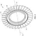
- FIG. 2 illustrates a perspective view of an exemplary configuration of a bladed rotor 66.
- the bladed rotor 66 of FIG. 2 may be configured for use with the low-pressure compressor 30 (e.g., the bladed second compressor rotor 56) and/or the high-pressure compressor 32 (e.g., the bladed first compressor rotor 50) of the gas turbine engine 20 of FIG. 1 .
- the present disclosure is not limited to compressor rotor configurations and the bladed rotor 66 may be a bladed turbine rotor, a bladed fan rotor, or any other bladed rotor configuration.
- the bladed rotor 66 of FIG. 2 includes a disk 68 and a plurality of blades 70.
- the disk 68 extends circumferentially about (e.g., completely around) an axial centerline 72 (e.g., a rotational axis).
- the plurality of blades 70 are circumferentially distributed about the disk 68.
- the plurality of blades 70 are mounted to the disk 68 (e.g., to a radial periphery of the disk 68).
- Each of the plurality of blades 70 may be positioned within an axially extending slot (e.g., a dovetail slot) formed by the disk 68.
- the plurality of blades 70 may be formed with the disk 68 as a unitary component (e.g., the bladed rotor 66 may be configured as an integrated blade rotor (IBR) or "blisk").
- IBR integrated blade rotor
- blisk blisk
- FIG. 3 illustrates a perspective view of an exemplary configuration for one of the blades 70.
- the blade 70 of FIG. 3 includes a blade body 74, a platform 76, and a root 78.
- the blade body 74 extends between and to a base end 80 of the blade body 74 and a tip end 82 of the blade body 74.
- the base end 80 is mounted to or otherwise disposed at (e.g., on, adjacent, or proximate) the platform 76.
- the tip end 82 is an outer radial end of the blade 70 relative to the axial centerline 72 (see FIG. 2 ).
- the blade body 74 extends between and to a leading edge 84 of the blade body 74 and a trailing edge 86 of the blade body 74.
- the leading edge 84 and the trailing edge 86 extend between and to the base end 80 and the tip end 82.
- the blade body 74 has a chord line 88 extending through the leading edge 84 and the trailing edge 86.
- the blade body 74 includes a pressure side surface 90 and a suction side surface 92.
- the pressure side surface 90 is disposed opposite (e.g., circumferentially opposite) the blade body 74 from the suction side surface 92.
- the pressure side surface 90 and the suction side surface 92 may extend between and to the base end 80 and the tip end 82.
- the pressure side surface 90 and the suction side surface 92 extend between and to the leading edge 84 and the trailing edge 86.
- the platform 76 may form a portion of an inner radial airflow surface 94 through the compressor section 24 (see FIG. 1 ).
- the root 78 is disposed radially inward of the platform 76.
- the root 78 is configured for mounting the blade 70 of FIG. 3 to a rotor disk, such as the disk 68 of FIG. 2 .
- Certification of an aircraft engine may include the performance of a "blade-off" test to demonstrate the capability of the aircraft engine for rotor blade containment and for subsequent rotation with bladed rotor imbalance (e.g., during an engine shutdown following the blade-off condition).
- a blade-off test includes the intentional separation of a large portion (e.g., greater than 80 percent) of a test rotor blade (e.g., a compressor rotor blade) during operation of the aircraft engine.
- the performance of a blade-off test for an aircraft engine poses design challenges as there are strict requirements on the speed and kinetic energy that the separable portion of the test rotor blade must be released with during the intentional separation. Therefore, the test rotor blade should be designed such that the test rotor blade does not release the separable portion prematurely before reaching the target bladed rotor rotational speed and does release the separable portion at the target bladed rotor rotational speed.
- FIG. 4 illustrates a cutaway view of a test rotor blade 96 of the rotor blades 70 for use in the performance of an aircraft engine blade-off test.
- the blade body 74 of the test rotor blade 96 forms a leading-edge pocket 98, a trailing-edge pocket 100, and a hole 102.
- the leading-edge pocket 98, the trailing-edge pocket 100, and the hole 102 are oriented along a target fracture plane 104 for the test rotor blade 96.
- the target fracture plane 104 represents an intended location of separation of an outer radial portion 106 of the test rotor blade 96 (e.g., the blade body 74) from an inner radial portion 108 of the test rotor blade 96 (e.g., the blade body 74) at a particular radial height of the test rotor blade 96 during a blade-off test.
- the leading-edge pocket 98 is disposed at (e.g., on, adjacent, or proximate) the leading edge 84.
- the trailing-edge pocket 100 is disposed at (e.g., on, adjacent, or proximate) the trailing edge 86.
- the hole 102 may extend through the blade body 74 between and to the leading-edge pocket 98 and the trailing-edge pocket 100.
- the hole 102 of FIG. 4 extends between and to a first end 110 of the hole 102 at the leading-edge pocket 98 and a second end 112 of the hole 102 at the trailing-edge pocket 100.
- the hole 102 has a length L H extending from the first end 110 to the second end 112.
- the hole 102 may have a diameter which is less than respective diameters, widths, heights, etc. of the leading-edge pocket 98 and/or the trailing-edge pocket 100.
- the leading-edge pocket 98 and the trailing-edge pocket 100 may be formed by slots, holes, or other apertures at the leading edge 84 and the trailing edge 86, respectively.
- the leading-edge pocket 98 and the trailing-edge pocket 100 may be formed through the pressure side surface 90 and the suction side surface 92 at (e.g., on, adjacent, or proximate) the leading edge 84 and the trailing edge 86, respectively.
- the hole 102 may be formed through the blade body 74 with a variety of different shapes, orientations, and configurations. For example, as shown in FIG.
- the hole 102 may extend linearly or substantially linearly from the first end 110 to the second end 112, for example, along the chord line 88 (see FIG. 4 ).
- the hole 102 may alternatively include a curvature along all or a portion of the length L H from the first end 110 to the second end 112 (see FIG. 4 ).
- the hole 102 may have a curvature matching a curvature of the pressure side surface 90 or the suction side surface 92.
- the hole 102 may alternatively include a plurality of linear or substantially linear segments. For example, each linear segment may have an axial centerline different than one or more other linear segment.
- a linear segment may have a diameter which is different than a diameter of one or more other linear segments.
- a first linear segment of the hole 102 may be formed (e.g., drilled) from the leading-edge pocket 98 to a mid-chord position of the blade body 74 and a second linear segment of the hole 102 may be formed (e.g., drilled) from the trailing-edge pocket 100 to intersect the first linear segment at the mid-chord position.
- the hole 102 may include an enlarged-diameter hole portion, which enlarged-diameter hole portion may be a diameter that is greater than in adjacent portions of the hole 102.
- the hole 102 may include the enlarged-diameter hole portion at one or both of the leading-edge pocket 98 and the trailing edge pocket 100.
- the enlarged-diameter hole portions may form linear segments of the hole 102 while smaller-diameter adjacent portions of the hole 102 may be curved.
- the present disclosure is not limited to the foregoing exemplary configurations of the hole 102.
- a thermal charge 114 is deposited within the hole 102.
- the thermal charge 114 may additionally be deposited within portions of the leading-edge pocket 98 and/or the trailing-edge pocket 100.
- the thermal charge 114 may preferably include a thermite material.
- the thermite material is configured to be ignited (e.g., by an igniter installed in the test rotor blade 96) and to undergo an exothermic reduction-oxidation reaction, briefly exposing the material (e.g., titanium) of the blade body 74 at (e.g., on, adjacent, or proximate) the hole 102 to high-temperature conditions, thereby reducing the tensile properties of the blade body 74 material to effect separation of the test rotor blade 96 at a target bladed rotor rotational speed.
- an igniter installed in the test rotor blade 96 e.g., by an igniter installed in the test rotor blade 96
- an exothermic reduction-oxidation reaction briefly exposing the material (e.g., titanium) of the blade body 74 at (e.g., on, adjacent, or proximate) the hole 102 to high-temperature conditions, thereby reducing the tensile properties of the blade body 74 material to effect separation of the test rotor
- the thermal charge 114 may alternatively include an explosive material (e.g., cyclotrimethylene trinitramine (RDX)) or another suitable ignitable material configured to effect separation of the test rotor blade 96 at the target fracture plane 104 by heating, penetrating, weakening, melting, or otherwise degrading the material of the blade body 74 at (e.g., on, adjacent, or proximate) the hole 102.
- the leading-edge pocket 98 and/or the trailing-edge pocket 100 may accommodate a plug and/or an igniter for the thermal charge 114.
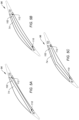
- FIGS. 6A and 6B illustrate different exemplary positions of the hole 102 relative to the pressure side surface 90 and the suction side surface 92.
- FIGS. 6A and 6B illustrate sectional views of the test rotor blade 96 at the first end 110 along the plane 116 of FIG. 4 .
- the test rotor blade 96 (e.g., the blade body 74) includes a pressure side wall 118 and a suction side wall 120.
- the pressure side wall 118 extends between and to the hole 102 and the pressure side surface 90 and, thereby, forms portions of the pressure side surface 90 and the hole 102.
- the pressure side wall 118 has a thickness T P extending from the pressure side surface 90 to the hole 102.
- the thickness T P is a minimum distance between the pressure side surface 90 and the hole 102 at a given point along the length L H of the hole 102 (see FIG. 4 ).
- the suction side wall 120 extends between and to the hole 102 and the suction side surface 92 and, thereby, forms portions of the suction side surface 92 and the hole 102.
- the suction side wall 120 has a thickness Ts extending from the suction side surface 92 to the hole 102.
- the thickness Ts is a minimum distance between the suction side surface 92 and the hole 102 at a given point along the length L H of the hole 102.
- the thickness T P is different than the thickness Ts.
- the present disclosure configuration of the thickness T P relative to the thickness T S facilitates improved reliability of the test rotor blade 96 for blade-off tests by increasing the likelihood of successful test rotor blade 96 separation at the target bladed rotor rotational speed, compared to at least some conventional rotor blades configured for blade-off tests.
- the centrifugal forces from bladed rotor rotation and the resulting stresses experienced by the walls on at (e.g., on, adjacent, or proximate) the fracture plane (e.g., during thermal charge ignition) may be the same or substantially the same for each of the side walls.
- the temperatures generated by ignition of the thermal charge may not sufficiently reduce the tensile capability of the test rotor blade body material to allow the test rotor blade to separate at the target bladed rotor rotational speed.
- the present disclosure configuration of the thickness T P relative to the thickness Ts may additionally facilitate a reduction in the likelihood of premature test rotor blade 96 separation.
- the hole 102 of FIGS. 6A and 6B is illustrated with a substantially circular cross-sectional shape, however, it should be understood that the present disclosure is not limited to any particular cross-sectional shape for the hole 102.
- the thickness Ts of the suction side wall 120 is less than the thickness T P of the pressure side wall 118.
- the following inequality [1] may be satisfied: 0.4 ⁇ T S T P ⁇ 0.9
- the thickness T S may be within a thickness range of 0.4T P to 0.9T P .
- the thickness Ts may be within the 0.4T H to 0.9T P thickness range along all or a substantial portion of the length L H of the hole 102 (see FIG. 4 ). Additionally or alternatively, an average of the thickness T S along the entire length L H of the hole 102 may be within the 0.4T P to 0.9T P thickness range.
- the relatively thicker pressure side wall 118 may resist fracturing at the target bladed rotor rotational speed, thereby increasing the likelihood of a failure of the test rotor blade 96 to separate at the target bladed rotor rotational speed.
- the likelihood of a failure of the test rotor blade 96 to separate at the target bladed rotor rotational speed may be increased, for example, due to the relatively close values of the thickness T S and the thickness T P .
- the thickness T P of the pressure side wall 118 is less than the thickness Ts of the suction side wall 120.
- the thickness T P may be within a thickness range of 0.4T S to 0.9T S .
- the thickness T P may be within the 0.4Ts to 0.9Ts thickness range along all or a substantial portion of the length L H of the hole 102 (see FIG. 4 ). Additionally or alternatively, an average of the thickness T P along the entire length L H of the hole 102 may be within the 0.4Ts to 0.9Ts thickness range.
- the relatively thicker suction side wall 120 may resist fracturing at the target bladed rotor rotational speed, thereby increasing the likelihood of a failure of the test rotor blade 96 to separate at the target bladed rotor rotational speed.
- the likelihood of a failure of the test rotor blade 96 to separate at the target bladed rotor rotational speed may be increased, for example, due to the relatively close values of the thickness T S and the thickness T P .
- the pressure side wall 118 and/or the suction side wall 120 may be locally shaped to control the relative thicknesses T P , T S (e.g., to establish the aforementioned thickness ranges along the hole 102).
- the pressure side wall 118 e.g., the pressure side surface 90
- the suction side wall 120 e.g., the suction side surface 92
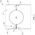
- the groove 122 of FIG. 7 includes a groove 122 formed by the suction side wall 120 on the suction side surface 92 at (e.g., on, adjacent, or proximate) the location of the thickness Ts.
- the groove 122 of FIG. 7 has a depth D G relative to the surrounding portions of the suction side surface 92 outside the groove 122.
- the depth D G may be constant or substantially constant along the length L H of the hole 102 (see FIG. 4 ).
- the depth D G may vary along the length L H of the hole 102, for example, to account for localized variations in the shape of the test rotor blade 96.
- the present disclosure is not limited to the particular shape or positioning of the groove 122 of FIG. 7 . While the groove 122 of FIG. 7 is illustrated on the side wall (e.g., the suction side wall 120) having thinner wall thickness (e.g., relative to the pressure side wall 118), the groove 122 may additionally or alternatively be disposed on the side wall having the thicker wall thickness
- the thicker side wall e.g., one of the pressure side wall 118 or the suction side wall 120
- the thinner side wall e.g., the other of the pressure side wall 118 or the suction side wall 120.
- the thicker side wall may carry enough of the centrifugal load such that there is minimal risk of premature separation of the outer radial portion 106.
- the thinner side wall experiences a significantly greater temperature increase relative to the thicker side wall. Additionally, for example, the thinner side wall experiences a significantly greater temperature increase relative to alternative test rotor blade configurations having side wall thicknesses which are substantially the same. Due to the temperature increase, the tensile capabilities of the thinner side wall will fall below the applied stress level, resulting in fracturing of the thinner side wall along the target fracture plane 104 (see FIG. 4 ).
- the stresses experienced by the thicker side wall significantly increase due to a reduction in the test rotor blade 96 material along the target fracture plane 104 as well as the additional bending loads applied to the test rotor blade 96 at the thicker side wall, thereby facilitating fracture of the thicker side wall and separation of the outer radial portion 106 at the target bladed rotor rotational speed.
- any one of these structures may describe the operations as a sequential process, many of the operations can be performed in parallel or concurrently.
- the order of the operations may be rearranged.
- a process may correspond to a method, a function, a procedure, a subroutine, a subprogram, etc.
Landscapes
- Engineering & Computer Science (AREA)
- Mechanical Engineering (AREA)
- General Engineering & Computer Science (AREA)
- Chemical & Material Sciences (AREA)
- Combustion & Propulsion (AREA)
- Physics & Mathematics (AREA)
- General Physics & Mathematics (AREA)
- Structures Of Non-Positive Displacement Pumps (AREA)
Abstract
A test rotor blade (96) for an aircraft engine bladed rotor includes a blade body (74) that extends between and to a leading edge (84) and a trailing edge (86) and forms a first side surface and a second side surface. The blade body (74) forms a leading-edge pocket (98) at the leading edge (84), a trailing-edge pocket (100) at the trailing edge (86), and a hole (102) extending through the blade body (74) from the leading-edge pocket (98) to the trailing edge pocket (100). The blade body (74) includes a first side wall and a second side wall. The first side wall has a first wall thickness extending between and to the first side surface and the hole (102). The second side wall has a second wall thickness extending between and to the second side surface and the hole (102). The second wall thickness is 0.4 to 0.9 times the first wall thickness.
Description
- This invention relates generally to blade-off tests for aircraft engine rotors and, more particularly, to a test rotor blade configured for use in a blade-off test for an aircraft engine rotor.
- A bladed rotor for an aircraft engine (e.g., a gas turbine engine) may include a plurality of rotor blades distributed about the bladed rotor. Aircraft engine testing may, in some cases, include the performance of a blade-off test for a bladed rotor. The blade-off test evaluates a response of the aircraft engine to a blade-off event in which at least a portion of a rotor blade separates from the bladed rotor during bladed rotor operation. The blade-off test may be performed using a test rotor blade configured to be selectively separated (e.g., fractured) to initiate a blade-off event. Various test rotor blade configurations and blade-off tests processes are known in the art. While the known configurations and processes have various advantages, there is still room in the art for improvement.
- It should be understood that any or all of the features or embodiments described herein can be used or combined in any combination with each and every other feature or embodiment described herein unless expressly noted otherwise.
- According to an aspect of the present invention, a test rotor blade for an aircraft engine bladed rotor includes a blade body. The blade body extends between and to a base end and a tip end. The blade body extends between and to a leading edge and a trailing edge. The blade body forms a first side surface and a second side surface. Each of the first side surface and the second side surface extend from the leading edge to the trailing edge. The blade body forms a leading-edge pocket at the leading edge, a trailing-edge pocket at the trailing edge, and a hole extending through the blade body from the leading-edge pocket to the trailing edge pocket. the hole includes a first end, a second end, and a hole length from the first end to the second end. The first end is disposed at the leading-edge pocket. The second end is disposed at the trailing-edge pocket. The blade body includes a first side wall and a second side wall. The first side wall has a first wall thickness extending between and to the first side surface and the hole. The second side wall has a second wall thickness extending between and to the second side surface and the hole. The second wall thickness is 0.4 to 0.9 times the first wall thickness.
- In any of the aspects or embodiments described above and herein, the first side surface may be a pressure side surface of the blade body and the second side surface may be a suction side surface of the blade body.
- In any of the aspects or embodiments described above and herein, the first side surface may be a suction side surface of the blade body and the second side surface may be a pressure side surface of the blade body.
- In any of the aspects or embodiments described above and herein, the second wall thickness may be 0.4 to 0.9 times the first wall thickness for all of the hole length of the hole.
- In any of the aspects or embodiments described above and herein, the first wall thickness may be a first average wall thickness extending between and to the first side surface and the hole along the hole length and the second wall thickness may be a second average wall thickness extending between and to the second side surface and the hole along the hole length.
- In any of the aspects or embodiments described above and herein, the hole may extend linearly from the first end to the second end.
- In any of the aspects or embodiments described above and herein, the hole may be curved between the first end and the second end.
- In any of the aspects or embodiments described above and herein, the hole may form plurality of linear segments between the first end and the second end.
- In any of the aspects or embodiments described above and herein, the blade body may form a groove on the second side surface at a location of the second wall thickness.
- In any of the aspects or embodiments described above and herein, the test rotor blade may further include a thermite thermal charge disposed within the hole.
- According to another aspect of the present invention, a gas turbine engine for an aircraft propulsion system includes a compressor. The compressor includes a bladed compressor rotor. The bladed compressor rotor includes a plurality of rotor blades. The plurality of rotor blades includes a test rotor blade (e.g., a test rotor blade according to any of the aspects or embodiments described above and herein). The test rotor blade includes a blade body. The blade body extends between and to a base end and a tip end. The blade body extends between and to a leading edge and a trailing edge. The blade body forms a first or pressure side surface and a second or suction side surface. Each of the first or pressure side surface and the second or suction side surface extends from the leading edge to the trailing edge. The blade body forms a hole extending through the blade body between the leading edge and the trailing edge. The blade body includes a first or pressure side wall and a second or suction side wall. The first or pressure side wall forms a portion of the first or pressure side surface and the hole. The first or pressure side wall has a first wall thickness extending between and to the first or pressure side surface and the hole. The second or suction side wall forms a portion of the second or suction side surface and the hole. The second or suction side wall has a second wall thickness extending between and to the second or suction side surface and the hole. The second wall thickness is different than the first wall thickness.
- In any of the aspects or embodiments described above and herein, the first thickness may be greater than the second thickness.
- In any of the aspects or embodiments described above and herein, the second thickness may be greater than the first thickness.
- In any of the aspects or embodiments described above and herein, the first wall thickness and the second wall thickness may be disposed at a target fracture plane for the test rotor blade.
- In any of the aspects or embodiments described above and herein, the blade body may further form a leading-edge pocket at the leading edge and a trailing-edge pocket at the trailing edge. The hole may extend through the blade body from the leading-edge pocket to the trailing edge pocket.
- According to another aspect of the present invention, a test rotor blade for an aircraft engine bladed rotor includes a blade body. The blade body extends between and to a base end and a tip end. The blade body extends between and to a leading edge and a trailing edge. The blade body forms a first side surface and a second side surface. Each of the first side surface and the second side surface extend from the leading edge to the trailing edge. The blade body forms a leading-edge pocket at the leading edge, a trailing-edge pocket at the trailing edge, and a hole extending through the blade body from the leading-edge pocket to the trailing edge pocket. The hole includes a first end, a second end, and a hole length from the first end to the second end. The first end is disposed at the leading-edge pocket. The second end is disposed at the trailing-edge pocket. The blade body includes a first side wall and a second side wall. The first side wall has a first wall thickness extending between and to the first side surface and the hole. The second side wall has a second wall thickness extending between and to the second side surface and the hole. The first wall thickness is greater than the second wall thickness for all of the hole length of the hole.
- In any of the aspects or embodiments described above and herein, the first side surface may be a pressure side surface of the blade body and the second side surface may be a suction side surface of the blade body.
- In any of the aspects or embodiments described above and herein, the first side surface may be a suction side surface of the blade body and the second side surface may be a pressure side surface of the blade body.
- In any of the aspects or embodiments described above and herein, the blade body may form a groove on the second side surface at a location of the second wall thickness.
- In any of the aspects or embodiments described above and herein, the groove may extend along the blade body at the location of the second wall thickness for all of the hole length.
- The present disclosure, and all its aspects, embodiments and advantages associated therewith will become more readily apparent in view of the detailed description provided below, including the accompanying drawings.
-
-
FIG. 1 schematically illustrates a cutaway, side view of a gas turbine engine for an aircraft propulsion system, in accordance with one or more embodiments of the present disclosure. -
FIG. 2 illustrates perspective view of a bladed rotor for a gas turbine engine, in accordance with one or more embodiments of the present disclosure. -
FIG. 3 illustrates a perspective view of a rotor blade for a bladed rotor, in accordance with one or more embodiments of the present disclosure. -
FIG. 4 illustrates a cutaway view of a test rotor blade for use on a bladed rotor during a blade-off test, in accordance with one or more embodiments of the present disclosure. -
FIGS. 5A-E illustrate cutaway views of different hole configurations for a test rotor blade, in accordance with one or more embodiments of the present disclosure. -
FIGS. 6A-B illustrate sectional views of different side wall configurations for a test rotor blade, in accordance with one or more embodiments of the present disclosure. -
FIG. 7 illustrates a sectional view of another side wall configuration for a test rotor blade, in accordance with one or more embodiments of the present disclosure. -
FIG. 1 schematically illustrates agas turbine engine 20. Thegas turbine engine 20 ofFIG. 1 is a multi-spool turbofan gas turbine engine for an aircraft propulsion system. However, while the following description and accompanying drawings may refer to the turbofangas turbine engine 20 ofFIG. 1 as an example, it should be understood that aspects of the present disclosure may be equally applicable to other types of gas turbine engines including, but not limited to, a turboshaft gas turbine engine, a turboprop gas turbine engine, a turbojet gas turbine engine, a propfan gas turbine engine, or an open rotor gas turbine engine. Moreover, the present disclosure may also be equally applicable to rotational equipment other than gas turbine engines. - The
gas turbine engine 20 ofFIG. 1 includes afan section 22, acompressor section 24, acombustor section 26, and aturbine section 28. For example, thecompressor section 24 ofFIG. 1 includes a low-pressure compressor (LPC) 30 and a high-pressure compressor (HPC) 32, the combustor section 16 includes a combustor 34 (e.g., an annular combustor), and theturbine section 28 includes a high-pressure turbine (HPT) 36 and a low-pressure turbine (LPT) 38. - The
gas turbine engine 20sections gas turbine engine 20. The firstrotational assembly 40 and the secondrotational assembly 42 are mounted for rotation about a rotational axis 44 (e.g., an axial centerline of the gas turbine engine 20) relative to the enginestatic structure 46 of thegas turbine engine 20. The enginestatic structure 46 may include one or more engine cases, cowlings, bearing assemblies, and/or other non-rotating structures configured to house and/or support components of thegas turbine engine 20sections - The first
rotational assembly 40 includes afirst shaft 48, a bladedfirst compressor rotor 50 for the high-pressure compressor 32, and a bladedfirst turbine rotor 52 for the high-pressure turbine 36. Thefirst shaft 48 interconnects the bladedfirst compressor rotor 50 and the bladedfirst turbine rotor 52. - The second
rotational assembly 42 includes asecond shaft 54, a bladedsecond compressor rotor 56 for the low-pressure compressor 30, and a bladedsecond turbine rotor 58 for the low-pressure turbine 38. Thesecond shaft 54 interconnects the bladedsecond compressor rotor 56 and the bladedsecond turbine rotor 58. Thesecond shaft 54 ofFIG. 1 additionally interconnects the bladedsecond compressor rotor 56 and the bladedsecond turbine rotor 58 with abladed fan rotor 60 for thefan section 22. Thesecond shaft 54 may alternatively be coupled to the bladed fan rotor 60 (e.g., an input shaft of the bladed fan rotor 60) by a reduction gear assembly configured to drive thebladed fan rotor 60 at a reduced rotational speed relative to thesecond shaft 54. - In operation of the
gas turbine engine 20 ofFIG. 1 , ambient air is directed through thefan section 22 and into acore flow path 62 and abypass flow path 64 by rotation of thebladed fan rotor 60. Airflow along thecore flow path 62 is compressed by the low-pressure compressor 30 and the high-pressure compressor 32, mixed and burned with fuel in thecombustor 34, and then directed through the high-pressure turbine 36 and the low-pressure turbine 38. The bladedfirst turbine rotor 52 and the bladedsecond turbine rotor 58 rotationally drive the firstrotational assembly 40 and the secondrotational assembly 42, respectively, in response to the combustion gas flow through the high-pressure turbine 36 and the low-pressure turbine 38. Thefirst shaft 48 and thesecond shaft 54 are concentric and rotate about therotational axis 44. The present disclosure, however, is not limited to concentric configurations of thefirst shaft 48 and thesecond shaft 54 and thefirst shaft 48 and thesecond shaft 54 may alternatively be configured for rotation about discrete rotational axes. -
FIG. 2 illustrates a perspective view of an exemplary configuration of abladed rotor 66. In particular, thebladed rotor 66 ofFIG. 2 may be configured for use with the low-pressure compressor 30 (e.g., the bladed second compressor rotor 56) and/or the high-pressure compressor 32 (e.g., the bladed first compressor rotor 50) of thegas turbine engine 20 ofFIG. 1 . The present disclosure, however, is not limited to compressor rotor configurations and thebladed rotor 66 may be a bladed turbine rotor, a bladed fan rotor, or any other bladed rotor configuration. Thebladed rotor 66 ofFIG. 2 includes adisk 68 and a plurality ofblades 70. Thedisk 68 extends circumferentially about (e.g., completely around) an axial centerline 72 (e.g., a rotational axis). The plurality ofblades 70 are circumferentially distributed about thedisk 68. The plurality ofblades 70 are mounted to the disk 68 (e.g., to a radial periphery of the disk 68). Each of the plurality ofblades 70 may be positioned within an axially extending slot (e.g., a dovetail slot) formed by thedisk 68. Alternatively, the plurality ofblades 70 may be formed with thedisk 68 as a unitary component (e.g., thebladed rotor 66 may be configured as an integrated blade rotor (IBR) or "blisk"). The present disclosure, however, is not limited to any particular arrangement or mounting configuration of the plurality ofblades 70 on thedisk 68. -
FIG. 3 illustrates a perspective view of an exemplary configuration for one of theblades 70. Theblade 70 ofFIG. 3 includes ablade body 74, aplatform 76, and aroot 78. - The
blade body 74 extends between and to abase end 80 of theblade body 74 and atip end 82 of theblade body 74. Thebase end 80 is mounted to or otherwise disposed at (e.g., on, adjacent, or proximate) theplatform 76. Thetip end 82 is an outer radial end of theblade 70 relative to the axial centerline 72 (seeFIG. 2 ). Theblade body 74 extends between and to aleading edge 84 of theblade body 74 and a trailingedge 86 of theblade body 74. The leadingedge 84 and the trailingedge 86 extend between and to thebase end 80 and thetip end 82. Theblade body 74 has achord line 88 extending through the leadingedge 84 and the trailingedge 86. Theblade body 74 includes apressure side surface 90 and asuction side surface 92. Thepressure side surface 90 is disposed opposite (e.g., circumferentially opposite) theblade body 74 from thesuction side surface 92. Thepressure side surface 90 and thesuction side surface 92 may extend between and to thebase end 80 and thetip end 82. Thepressure side surface 90 and thesuction side surface 92 extend between and to the leadingedge 84 and the trailingedge 86. Theplatform 76 may form a portion of an innerradial airflow surface 94 through the compressor section 24 (seeFIG. 1 ). Theroot 78 is disposed radially inward of theplatform 76. Theroot 78 is configured for mounting theblade 70 ofFIG. 3 to a rotor disk, such as thedisk 68 ofFIG. 2 . - Certification of an aircraft engine, such as the
gas turbine engine 20, may include the performance of a "blade-off" test to demonstrate the capability of the aircraft engine for rotor blade containment and for subsequent rotation with bladed rotor imbalance (e.g., during an engine shutdown following the blade-off condition). In general, a blade-off test includes the intentional separation of a large portion (e.g., greater than 80 percent) of a test rotor blade (e.g., a compressor rotor blade) during operation of the aircraft engine. The performance of a blade-off test for an aircraft engine poses design challenges as there are strict requirements on the speed and kinetic energy that the separable portion of the test rotor blade must be released with during the intentional separation. Therefore, the test rotor blade should be designed such that the test rotor blade does not release the separable portion prematurely before reaching the target bladed rotor rotational speed and does release the separable portion at the target bladed rotor rotational speed. -
FIG. 4 illustrates a cutaway view of atest rotor blade 96 of therotor blades 70 for use in the performance of an aircraft engine blade-off test. Theblade body 74 of thetest rotor blade 96 forms a leading-edge pocket 98, a trailing-edge pocket 100, and ahole 102. The leading-edge pocket 98, the trailing-edge pocket 100, and thehole 102 are oriented along atarget fracture plane 104 for thetest rotor blade 96. Thetarget fracture plane 104 represents an intended location of separation of an outerradial portion 106 of the test rotor blade 96 (e.g., the blade body 74) from an innerradial portion 108 of the test rotor blade 96 (e.g., the blade body 74) at a particular radial height of thetest rotor blade 96 during a blade-off test. The leading-edge pocket 98 is disposed at (e.g., on, adjacent, or proximate) the leadingedge 84. The trailing-edge pocket 100 is disposed at (e.g., on, adjacent, or proximate) the trailingedge 86. - The
hole 102 may extend through theblade body 74 between and to the leading-edge pocket 98 and the trailing-edge pocket 100. In particular, thehole 102 ofFIG. 4 extends between and to afirst end 110 of thehole 102 at the leading-edge pocket 98 and asecond end 112 of thehole 102 at the trailing-edge pocket 100. Thehole 102 has a length LH extending from thefirst end 110 to thesecond end 112. Thehole 102 may have a diameter which is less than respective diameters, widths, heights, etc. of the leading-edge pocket 98 and/or the trailing-edge pocket 100. The leading-edge pocket 98 and the trailing-edge pocket 100 may be formed by slots, holes, or other apertures at theleading edge 84 and the trailingedge 86, respectively. The leading-edge pocket 98 and the trailing-edge pocket 100 may be formed through thepressure side surface 90 and thesuction side surface 92 at (e.g., on, adjacent, or proximate) the leadingedge 84 and the trailingedge 86, respectively. Referring briefly toFIGS. 5A-E , thehole 102 may be formed through theblade body 74 with a variety of different shapes, orientations, and configurations. For example, as shown inFIG. 5A , thehole 102 may extend linearly or substantially linearly from thefirst end 110 to thesecond end 112, for example, along the chord line 88 (seeFIG. 4 ). As shown inFIG. 5B , thehole 102 may alternatively include a curvature along all or a portion of the length LH from thefirst end 110 to the second end 112 (seeFIG. 4 ). For example, thehole 102 may have a curvature matching a curvature of thepressure side surface 90 or thesuction side surface 92. As shown inFIG. 5C , thehole 102 may alternatively include a plurality of linear or substantially linear segments. For example, each linear segment may have an axial centerline different than one or more other linear segment. Additionally or alternatively, a linear segment may have a diameter which is different than a diameter of one or more other linear segments. For example, a first linear segment of thehole 102 may be formed (e.g., drilled) from the leading-edge pocket 98 to a mid-chord position of theblade body 74 and a second linear segment of thehole 102 may be formed (e.g., drilled) from the trailing-edge pocket 100 to intersect the first linear segment at the mid-chord position. As shown inFIGS. 5D and 5E , thehole 102 may include an enlarged-diameter hole portion, which enlarged-diameter hole portion may be a diameter that is greater than in adjacent portions of thehole 102. For example, thehole 102 may include the enlarged-diameter hole portion at one or both of the leading-edge pocket 98 and the trailingedge pocket 100. As shown inFIGS. 5D and 5E , the enlarged-diameter hole portions may form linear segments of thehole 102 while smaller-diameter adjacent portions of thehole 102 may be curved. The present disclosure, however, is not limited to the foregoing exemplary configurations of thehole 102. - To prepare the
test rotor blade 96 for an aircraft engine blade-off test, athermal charge 114 is deposited within thehole 102. Thethermal charge 114 may additionally be deposited within portions of the leading-edge pocket 98 and/or the trailing-edge pocket 100. Thethermal charge 114 may preferably include a thermite material. The thermite material is configured to be ignited (e.g., by an igniter installed in the test rotor blade 96) and to undergo an exothermic reduction-oxidation reaction, briefly exposing the material (e.g., titanium) of theblade body 74 at (e.g., on, adjacent, or proximate) thehole 102 to high-temperature conditions, thereby reducing the tensile properties of theblade body 74 material to effect separation of thetest rotor blade 96 at a target bladed rotor rotational speed. Thethermal charge 114 may alternatively include an explosive material (e.g., cyclotrimethylene trinitramine (RDX)) or another suitable ignitable material configured to effect separation of thetest rotor blade 96 at thetarget fracture plane 104 by heating, penetrating, weakening, melting, or otherwise degrading the material of theblade body 74 at (e.g., on, adjacent, or proximate) thehole 102. The leading-edge pocket 98 and/or the trailing-edge pocket 100 may accommodate a plug and/or an igniter for thethermal charge 114. -
FIGS. 6A and 6B illustrate different exemplary positions of thehole 102 relative to thepressure side surface 90 and thesuction side surface 92.FIGS. 6A and 6B illustrate sectional views of thetest rotor blade 96 at thefirst end 110 along theplane 116 ofFIG. 4 . The test rotor blade 96 (e.g., the blade body 74) includes apressure side wall 118 and asuction side wall 120. Thepressure side wall 118 extends between and to thehole 102 and thepressure side surface 90 and, thereby, forms portions of thepressure side surface 90 and thehole 102. Thepressure side wall 118 has a thickness TP extending from thepressure side surface 90 to thehole 102. The thickness TP is a minimum distance between thepressure side surface 90 and thehole 102 at a given point along the length LH of the hole 102 (seeFIG. 4 ). Similarly, thesuction side wall 120 extends between and to thehole 102 and thesuction side surface 92 and, thereby, forms portions of thesuction side surface 92 and thehole 102. Thesuction side wall 120 has a thickness Ts extending from thesuction side surface 92 to thehole 102. The thickness Ts is a minimum distance between thesuction side surface 92 and thehole 102 at a given point along the length LH of thehole 102. - As can be understood from
FIGS. 6A and 6B , the thickness TP is different than the thickness Ts. As will be discussed in further detail, the present disclosure configuration of the thickness TP relative to the thickness TS facilitates improved reliability of thetest rotor blade 96 for blade-off tests by increasing the likelihood of successfultest rotor blade 96 separation at the target bladed rotor rotational speed, compared to at least some conventional rotor blades configured for blade-off tests. For example, where side wall thicknesses (e.g., thickness TP and thickness TS) of a test rotor blade may be equal, the centrifugal forces from bladed rotor rotation and the resulting stresses experienced by the walls on at (e.g., on, adjacent, or proximate) the fracture plane (e.g., during thermal charge ignition) may be the same or substantially the same for each of the side walls. However, the temperatures generated by ignition of the thermal charge may not sufficiently reduce the tensile capability of the test rotor blade body material to allow the test rotor blade to separate at the target bladed rotor rotational speed. The present disclosure configuration of the thickness TP relative to the thickness Ts may additionally facilitate a reduction in the likelihood of prematuretest rotor blade 96 separation. Thehole 102 ofFIGS. 6A and 6B is illustrated with a substantially circular cross-sectional shape, however, it should be understood that the present disclosure is not limited to any particular cross-sectional shape for thehole 102. - Referring to
FIG. 6A , the thickness Ts of thesuction side wall 120 is less than the thickness TP of thepressure side wall 118. Where thesuction side wall 120 is thinner than thepressure side wall 118, the following inequality [1] may be satisfied:
FIG. 4 ). Additionally or alternatively, an average of the thickness TS along the entire length LH of thehole 102 may be within the 0.4TP to 0.9TP thickness range. With the thickness TS less than 0.4TP, there is a significantly increased likelihood of a premature failure of thesuction side wall 120 and, and a result, a premature separation of thetest rotor blade 96 prior to reaching the target bladed rotor rotational speed. However, in some other cases where the thickness TS less than 0.4TP, the relatively thickerpressure side wall 118 may resist fracturing at the target bladed rotor rotational speed, thereby increasing the likelihood of a failure of thetest rotor blade 96 to separate at the target bladed rotor rotational speed. With the thickness Ts greater than 0.9TP, the likelihood of a failure of thetest rotor blade 96 to separate at the target bladed rotor rotational speed may be increased, for example, due to the relatively close values of the thickness TS and the thickness TP. - Referring to
FIG. 6B , the thickness TP of thepressure side wall 118 is less than the thickness Ts of thesuction side wall 120. Where thepressure side wall 118 is thinner than thesuction side wall 120, the following inequality [2] may be satisfied:
FIG. 4 ). Additionally or alternatively, an average of the thickness TP along the entire length LH of thehole 102 may be within the 0.4Ts to 0.9Ts thickness range. With the thickness TP less than 0.4TS, there is a significantly increased likelihood of a premature failure of thepressure side wall 118 and, and a result, a premature separation of thetest rotor blade 96 prior to reaching the target bladed rotor rotational speed. However, in some other cases where the thickness TP less than 0.4TS, the relatively thickersuction side wall 120 may resist fracturing at the target bladed rotor rotational speed, thereby increasing the likelihood of a failure of thetest rotor blade 96 to separate at the target bladed rotor rotational speed. With the thickness TP greater than 0.9Ts, the likelihood of a failure of thetest rotor blade 96 to separate at the target bladed rotor rotational speed may be increased, for example, due to the relatively close values of the thickness TS and the thickness TP. - Referring to
FIG. 7 , in some embodiments, thepressure side wall 118 and/or thesuction side wall 120 may be locally shaped to control the relative thicknesses TP, TS (e.g., to establish the aforementioned thickness ranges along the hole 102). For example, the pressure side wall 118 (e.g., the pressure side surface 90) and/or the suction side wall 120 (e.g., the suction side surface 92) may be machined, etched, milled, cut, abraded, or otherwise formed at a location of the thickness TP and/or the thickness Ts. Thetest rotor blade 96 ofFIG. 7 , for example, includes agroove 122 formed by thesuction side wall 120 on thesuction side surface 92 at (e.g., on, adjacent, or proximate) the location of the thickness Ts. Thegroove 122 ofFIG. 7 has a depth DG relative to the surrounding portions of thesuction side surface 92 outside thegroove 122. The depth DG may be constant or substantially constant along the length LH of the hole 102 (seeFIG. 4 ). Alternatively, the depth DG may vary along the length LH of thehole 102, for example, to account for localized variations in the shape of thetest rotor blade 96. Of course, the present disclosure is not limited to the particular shape or positioning of thegroove 122 ofFIG. 7 . While thegroove 122 ofFIG. 7 is illustrated on the side wall (e.g., the suction side wall 120) having thinner wall thickness (e.g., relative to the pressure side wall 118), thegroove 122 may additionally or alternatively be disposed on the side wall having the thicker wall thickness. - Referring again to
FIGS. 6A and 6B , in operation, as the bladed rotor 66 (seeFIG. 2 ) is rotating in preparation for a blade-off test, the thicker side wall (e.g., one of thepressure side wall 118 or the suction side wall 120) carries a significantly larger proportion of the centrifugal load experienced by the outerradial portion 106, thereby alleviating the centrifugal load carried by the thinner side wall (e.g., the other of thepressure side wall 118 or the suction side wall 120). Accordingly, the thicker side wall may carry enough of the centrifugal load such that there is minimal risk of premature separation of the outerradial portion 106. When igniting the thermal charge 114 (seeFIG. 4 ) at the initiation of the blade-off test, the thinner side wall experiences a significantly greater temperature increase relative to the thicker side wall. Additionally, for example, the thinner side wall experiences a significantly greater temperature increase relative to alternative test rotor blade configurations having side wall thicknesses which are substantially the same. Due to the temperature increase, the tensile capabilities of the thinner side wall will fall below the applied stress level, resulting in fracturing of the thinner side wall along the target fracture plane 104 (seeFIG. 4 ). Once the thinner side wall fractures, the stresses experienced by the thicker side wall significantly increase due to a reduction in thetest rotor blade 96 material along thetarget fracture plane 104 as well as the additional bending loads applied to thetest rotor blade 96 at the thicker side wall, thereby facilitating fracture of the thicker side wall and separation of the outerradial portion 106 at the target bladed rotor rotational speed. - While the principles of the disclosure have been described above in connection with specific apparatuses and methods, it is to be clearly understood that this description is made only by way of example and not as limitation on the scope of the disclosure. Specific details are given in the above description to provide a thorough understanding of the embodiments. However, it is understood that the embodiments may be practiced without these specific details.
- It is noted that the embodiments may be described as a process which is depicted as a flowchart, a flow diagram, a block diagram, etc. Although any one of these structures may describe the operations as a sequential process, many of the operations can be performed in parallel or concurrently. In addition, the order of the operations may be rearranged. A process may correspond to a method, a function, a procedure, a subroutine, a subprogram, etc.
- The singular forms "a," "an," and "the" refer to one or more than one, unless the context clearly dictates otherwise. For example, the term "comprising a specimen" includes single or plural specimens and is considered equivalent to the phrase "comprising at least one specimen." The term "or" refers to a single element of stated alternative elements or a combination of two or more elements unless the context clearly indicates otherwise. As used herein, "comprises" means "includes." Thus, "comprising A or B," means "including A or B, or A and B," without excluding additional elements.
- It is noted that various connections are set forth between elements in the present description and drawings (the contents of which are included in this disclosure by way of reference). It is noted that these connections are general and, unless specified otherwise, may be direct or indirect and that this specification is not intended to be limiting in this respect. Any reference to attached, fixed, connected or the like may include permanent, removable, temporary, partial, full and/or any other possible attachment option.
- No element, component, or method step in the present disclosure is intended to be dedicated to the public regardless of whether the element, component, or method step is explicitly recited in the claims. As used herein, the terms "comprise", "comprising", or any other variation thereof, are intended to cover a non-exclusive inclusion, such that a process, method, article, or apparatus that comprises a list of elements does not include only those elements but may include other elements not expressly listed or inherent to such process, method, article, or apparatus.
- While various inventive aspects, concepts, and features of the disclosures may be described and illustrated herein as embodied in combination in the exemplary embodiments, these various aspects, concepts, and features may be used in many alternative embodiments, either individually or in various combinations and sub-combinations thereof. Unless expressly excluded herein all such combinations and sub-combinations are intended to be within the scope of the present application. Still further, while various alternative embodiments as to the various aspects, concepts, and features of the disclosures--such as alternative materials, structures, configurations, methods, devices, and components, and so on--may be described herein, such descriptions are not intended to be a complete or exhaustive list of available alternative embodiments, whether presently known or later developed. Those skilled in the art may readily adopt one or more of the inventive aspects, concepts, or features into additional embodiments and uses within the scope of the present application even if such embodiments are not expressly disclosed herein. For example, in the exemplary embodiments described above within the Detailed Description portion of the present specification, elements may be described as individual units and shown as independent of one another to facilitate the description. In alternative embodiments, such elements may be configured as combined elements.
Claims (15)
- A test rotor blade (96) for an aircraft engine bladed rotor (66), the test rotor blade (96) comprising:a blade body (74), wherein the blade body (74) extends between and to a base end (80) and a tip end (82), the blade body (74) extends between and to a leading edge (84) and a trailing edge (86), the blade body (74) forms a first side surface (90) and a second side surface (92), each of the first side surface (90) and the second side surface (92) extend from the leading edge (84) to the trailing edge (86), and the blade body (74) forms:a leading-edge pocket (98) at the leading edge (84);a trailing-edge pocket (100) at the trailing edge (86); anda hole (102) extending through the blade body (74) from the leading-edge pocket (98) to the trailing edge pocket (100), wherein the hole (102) includes a first end (110), a second end (112), and a hole length (LH) from the first end (110) to the second end (112), the first end (110) is disposed at the leading-edge pocket (98), and the second end (112) is disposed at the trailing-edge pocket (100);wherein the blade body (74) includes a first side wall (118) and a second side wall (120), the first side wall (118) has a first wall thickness extending between and to the first side surface (90) and the hole (102), the second side wall (120) has a second wall thickness extending between and to the second side surface (92) and the hole (102), and the second wall thickness is 0.4 to 0.9 times the first wall thickness.
- The test rotor blade (96) of claim 1, wherein:the first side surface is a pressure side surface (90) of the blade body (74) and the second side surface is a suction side surface (92) of the blade body (74); orthe first side surface is a suction side surface (92) of the blade body (74) and the second side surface is a pressure side surface (90) of the blade body (74).
- The test rotor blade (96) of claim 1 or 2, wherein the second wall thickness is 0.4 to 0.9 times the first wall thickness for all of the hole length (LH) of the hole (102).
- The test rotor blade (96) of claim 1 or 2, wherein the first wall thickness is a first average wall thickness extending between and to the first side surface and the hole (102) along the hole length (LH) and the second wall thickness is a second average wall thickness extending between and to the second side surface and the hole (102) along the hole length (LH).
- The test rotor blade (96) of any preceding claim, wherein:the hole (102) extends linearly from the first end (110) to the second end (112);the hole (102) is curved between the first end (110) and the second end (112); orthe hole (102) forms a plurality of linear segments between the first end (110) and the second end (112).
- A gas turbine engine (20) for an aircraft propulsion system, the gas turbine engine (20) comprising a compressor (30) including a bladed compressor rotor (66), wherein the bladed compressor rotor (66) includes a plurality of rotor blades (70), the plurality of rotor blades (70) includes a test rotor blade (96), and the test rotor blade (96) includes a blade body (74), wherein the blade body (74) extends between and to a base end (80) and a tip end (82), the blade body (74) extends between and to a leading edge (84) and a trailing edge (86), the blade body (74) forms a pressure side surface (90) and a suction side surface (92), each of the pressure side surface (90) and the suction side surface (92) extends from the leading edge (84) to the trailing edge (86), the blade body (74) forms a hole (102) extending through the blade body (74) between the leading edge (84) and the trailing edge (86), the blade body (74) includes a pressure side wall (118) and a suction side wall (120), the pressure side wall (118) forms a portion of the pressure side surface (90) and the hole (102), the pressure side wall (118) has a first wall thickness extending between and to the pressure side surface (90) and the hole (102), the suction side wall (120) forms a portion of the suction side surface (92) and the hole (102), the suction side wall (120) has a second wall thickness extending between and to the suction side surface (92) and the hole (102), and the second wall thickness is different than the first wall thickness.
- The gas turbine engine (20) of claim 6, wherein the first thickness is greater than the second thickness.
- The gas turbine engine (20) of claim 6, wherein the second thickness is greater than the first thickness.
- The gas turbine engine (20) of claim 5, 7 or 8, wherein the blade body (74) further forms a leading-edge pocket (98) at the leading edge (84) and a trailing-edge pocket (100) at the trailing edge (86), and the hole (102) extends through the blade body (74) from the leading-edge pocket (98) to the trailing edge pocket (100).
- A test rotor blade (96) for an aircraft engine bladed rotor (66), the test rotor blade (96) comprising:a blade body (74), wherein the blade body (74) extends between and to a base end (80) and a tip end (82), the blade body (74) extends between and to a leading edge (84) and a trailing edge (86), the blade body (74) forms a first side surface and a second side surface, each of the first side surface and the second side surface extend from the leading edge (84) to the trailing edge (86), and the blade body (74) forms:a leading-edge pocket (98) at the leading edge (84);a trailing-edge pocket (100) at the trailing edge (86); anda hole (102) extending through the blade body (74) from the leading-edge pocket (98) to the trailing edge pocket (100), wherein the hole (102) includes a first end (110), a second end (112), and a hole length (LH) from the first end (110) to the second end (112), the first end (110) is disposed at the leading-edge pocket (98), and the second end (112) is disposed at the trailing-edge pocket (100), wherein the blade body (74) includes a first side wall and a second side wall, the first side wall has a first wall thickness extending between and to the first side surface and the hole (102), the second side wall has a second wall thickness extending between and to the second side surface and the hole (102), and the first wall thickness is greater than the second wall thickness for all of the hole length (LH) of the hole (102).
- The test rotor blade (96) of claim 10, wherein:the first side surface is a pressure side surface (90) of the blade body (74) and the second side surface is a suction side surface (92) of the blade body (74); orthe first side surface is a suction side surface (92) of the blade body (74) and the second side surface is a pressure side surface (90) of the blade body (74).
- The gas turbine engine (20) or test rotor blade (96) of any preceding claim, wherein the blade body (74) forms a groove (122) on the second side surface at a location of the second wall thickness.
- The gas turbine engine (20) or test rotor blade (96) of claim 12, wherein the groove (122) extends along the blade body (74) at the location of the second wall thickness for all of the hole length (LH).
- The gas turbine engine (20) or test rotor blade (96) of any preceding claim, further comprising a thermite thermal charge (114) disposed within the hole (102).
- The gas turbine engine (20) or test rotor blade (96) of any preceding claim, wherein the first wall thickness and the second wall thickness are disposed at a target fracture plane (104) for the test rotor blade (96).
Applications Claiming Priority (1)
| Application Number | Priority Date | Filing Date | Title |
|---|---|---|---|
| US18/238,315 US12270310B2 (en) | 2023-08-25 | 2023-08-25 | Test rotor blade for an aircraft engine blade-off test |
Publications (1)
| Publication Number | Publication Date |
|---|---|
| EP4513007A1 true EP4513007A1 (en) | 2025-02-26 |
Family
ID=92539108
Family Applications (1)
| Application Number | Title | Priority Date | Filing Date |
|---|---|---|---|
| EP24196276.0A Pending EP4513007A1 (en) | 2023-08-25 | 2024-08-23 | Test rotor blade for an aircraft engine blade-off test |
Country Status (3)
| Country | Link |
|---|---|
| US (2) | US12270310B2 (en) |
| EP (1) | EP4513007A1 (en) |
| CA (1) | CA3253019A1 (en) |
Families Citing this family (1)
| Publication number | Priority date | Publication date | Assignee | Title |
|---|---|---|---|---|
| US12576991B1 (en) * | 2024-12-13 | 2026-03-17 | Rtx Corporation | Method for forming an inspection access passage for an aircraft propulsion system |
Citations (3)
| Publication number | Priority date | Publication date | Assignee | Title |
|---|---|---|---|---|
| FR3042536A1 (en) * | 2015-10-20 | 2017-04-21 | Snecma | BLOWER DAWN FOR TEST BENCH |
| US10113442B2 (en) * | 2016-07-15 | 2018-10-30 | Rolls-Royce Corporation | Method of releasing a fan blade and assembly for releasing a fan blade from a turbofan engine |
| CN115127823A (en) * | 2022-06-16 | 2022-09-30 | 中国航发沈阳发动机研究所 | Blade blasting cutting device for aero-engine containment test |
Family Cites Families (5)
| Publication number | Priority date | Publication date | Assignee | Title |
|---|---|---|---|---|
| US7841834B1 (en) * | 2006-01-27 | 2010-11-30 | Florida Turbine Technologies, Inc. | Method and leading edge replacement insert for repairing a turbine engine blade |
| US8685187B2 (en) * | 2009-12-23 | 2014-04-01 | Schlumberger Technology Corporation | Perforating devices utilizing thermite charges in well perforation and downhole fracing |
| US10260512B2 (en) | 2016-07-15 | 2019-04-16 | Rolls-Royce Corporation | Method for release of fan blisk airfoil with external shaped charge |
| US10774679B2 (en) * | 2018-02-09 | 2020-09-15 | General Electric Company | Turbine engine airfoil assembly |
| GB201917171D0 (en) * | 2019-11-26 | 2020-01-08 | Rolls Royce Plc | Gas turbine engine |
-
2023
- 2023-08-25 US US18/238,315 patent/US12270310B2/en active Active
-
2024
- 2024-08-23 EP EP24196276.0A patent/EP4513007A1/en active Pending
- 2024-08-23 CA CA3253019A patent/CA3253019A1/en active Pending
-
2025
- 2025-04-07 US US19/172,216 patent/US20250230757A1/en active Pending
Patent Citations (3)
| Publication number | Priority date | Publication date | Assignee | Title |
|---|---|---|---|---|
| FR3042536A1 (en) * | 2015-10-20 | 2017-04-21 | Snecma | BLOWER DAWN FOR TEST BENCH |
| US10113442B2 (en) * | 2016-07-15 | 2018-10-30 | Rolls-Royce Corporation | Method of releasing a fan blade and assembly for releasing a fan blade from a turbofan engine |
| CN115127823A (en) * | 2022-06-16 | 2022-09-30 | 中国航发沈阳发动机研究所 | Blade blasting cutting device for aero-engine containment test |
Also Published As
| Publication number | Publication date |
|---|---|
| US20250067195A1 (en) | 2025-02-27 |
| US20250230757A1 (en) | 2025-07-17 |
| CA3253019A1 (en) | 2025-06-04 |
| US12270310B2 (en) | 2025-04-08 |
Similar Documents
| Publication | Publication Date | Title |
|---|---|---|
| EP3663537B1 (en) | Methods and apparatus for controlling at least part of a start-up or re-light process of a gas turbine engine | |
| US10260512B2 (en) | Method for release of fan blisk airfoil with external shaped charge | |
| US20120051920A1 (en) | Root region of a blade for a gas turbine engine | |
| US20250230757A1 (en) | Test rotor blade for an aircraft engine blade-off test | |
| US10113442B2 (en) | Method of releasing a fan blade and assembly for releasing a fan blade from a turbofan engine | |
| US20200173368A1 (en) | Methods and apparatus for controlling at least part of a start-up or re-light process of a gas turbine engine | |
| EP3640439A1 (en) | Fan blade containment systems and corresponding gas turbine engine | |
| US20240328329A1 (en) | Method and integrally bladed rotor for blade off testing | |
| EP2589755B1 (en) | Rotatable component of a gas turbine with controlled load interface and corresponding method | |
| CN110259519B (en) | Turbine engine airfoil assembly | |
| EP2565384B1 (en) | Bladed rotor and corresponding assembling method | |
| US20190284954A1 (en) | Gas turbine engine and method of maintaining a gas turbine engine | |
| EP4513008A1 (en) | Test rotor blade for an aircraft engine blade-off test | |
| EP3287601B1 (en) | Multi-piece non-linear fan blade | |
| US10801361B2 (en) | System and method for HPT disk over speed prevention | |
| US11939877B1 (en) | Method and integrally bladed rotor for blade off testing | |
| CA3230861A1 (en) | Test blade for gas turbine engine and method of making | |
| EP4276294B1 (en) | Method of optimising gas turbine engine combustion equipment performance | |
| US11268386B2 (en) | Gas turbine engine having optimized fan | |
| EP3819480A1 (en) | Bracket | |
| US12480406B2 (en) | Turbine vane for a gas turbine engine | |
| EP4553293A1 (en) | Strut for bearing assembly and method for removing strut | |
| US20220090504A1 (en) | Rotor blade for a gas turbine engine having a metallic structural member and a composite fairing |
Legal Events
| Date | Code | Title | Description |
|---|---|---|---|
| PUAI | Public reference made under article 153(3) epc to a published international application that has entered the european phase |
Free format text: ORIGINAL CODE: 0009012 |
|
| STAA | Information on the status of an ep patent application or granted ep patent |
Free format text: STATUS: THE APPLICATION HAS BEEN PUBLISHED |
|
| AK | Designated contracting states |
Kind code of ref document: A1 Designated state(s): AL AT BE BG CH CY CZ DE DK EE ES FI FR GB GR HR HU IE IS IT LI LT LU LV MC ME MK MT NL NO PL PT RO RS SE SI SK SM TR |
|
| STAA | Information on the status of an ep patent application or granted ep patent |
Free format text: STATUS: REQUEST FOR EXAMINATION WAS MADE |
|
| 17P | Request for examination filed |
Effective date: 20250826 |