EP4513001A1 - Gas turbine engine - Google Patents
Gas turbine engine Download PDFInfo
- Publication number
- EP4513001A1 EP4513001A1 EP24196285.1A EP24196285A EP4513001A1 EP 4513001 A1 EP4513001 A1 EP 4513001A1 EP 24196285 A EP24196285 A EP 24196285A EP 4513001 A1 EP4513001 A1 EP 4513001A1
- Authority
- EP
- European Patent Office
- Prior art keywords
- face
- section
- cmc
- gas turbine
- vane arc
- Prior art date
- Legal status (The legal status is an assumption and is not a legal conclusion. Google has not performed a legal analysis and makes no representation as to the accuracy of the status listed.)
- Pending
Links
Images


Classifications
-
- F—MECHANICAL ENGINEERING; LIGHTING; HEATING; WEAPONS; BLASTING
- F01—MACHINES OR ENGINES IN GENERAL; ENGINE PLANTS IN GENERAL; STEAM ENGINES
- F01D—NON-POSITIVE DISPLACEMENT MACHINES OR ENGINES, e.g. STEAM TURBINES
- F01D25/00—Component parts, details, or accessories, not provided for in, or of interest apart from, other groups
- F01D25/04—Antivibration arrangements
- F01D25/06—Antivibration arrangements for preventing blade vibration
-
- F—MECHANICAL ENGINEERING; LIGHTING; HEATING; WEAPONS; BLASTING
- F01—MACHINES OR ENGINES IN GENERAL; ENGINE PLANTS IN GENERAL; STEAM ENGINES
- F01D—NON-POSITIVE DISPLACEMENT MACHINES OR ENGINES, e.g. STEAM TURBINES
- F01D5/00—Blades; Blade-carrying members; Heating, heat-insulating, cooling or antivibration means on the blades or the members
- F01D5/12—Blades
- F01D5/28—Selecting particular materials; Particular measures relating thereto; Measures against erosion or corrosion
- F01D5/282—Selecting composite materials, e.g. blades with reinforcing filaments
-
- F—MECHANICAL ENGINEERING; LIGHTING; HEATING; WEAPONS; BLASTING
- F01—MACHINES OR ENGINES IN GENERAL; ENGINE PLANTS IN GENERAL; STEAM ENGINES
- F01D—NON-POSITIVE DISPLACEMENT MACHINES OR ENGINES, e.g. STEAM TURBINES
- F01D5/00—Blades; Blade-carrying members; Heating, heat-insulating, cooling or antivibration means on the blades or the members
- F01D5/12—Blades
- F01D5/22—Blade-to-blade connections, e.g. for damping vibrations
-
- F—MECHANICAL ENGINEERING; LIGHTING; HEATING; WEAPONS; BLASTING
- F01—MACHINES OR ENGINES IN GENERAL; ENGINE PLANTS IN GENERAL; STEAM ENGINES
- F01D—NON-POSITIVE DISPLACEMENT MACHINES OR ENGINES, e.g. STEAM TURBINES
- F01D5/00—Blades; Blade-carrying members; Heating, heat-insulating, cooling or antivibration means on the blades or the members
- F01D5/12—Blades
- F01D5/28—Selecting particular materials; Particular measures relating thereto; Measures against erosion or corrosion
- F01D5/284—Selection of ceramic materials
-
- F—MECHANICAL ENGINEERING; LIGHTING; HEATING; WEAPONS; BLASTING
- F01—MACHINES OR ENGINES IN GENERAL; ENGINE PLANTS IN GENERAL; STEAM ENGINES
- F01D—NON-POSITIVE DISPLACEMENT MACHINES OR ENGINES, e.g. STEAM TURBINES
- F01D9/00—Stators
- F01D9/02—Nozzles; Nozzle boxes; Stator blades; Guide conduits, e.g. individual nozzles
- F01D9/04—Nozzles; Nozzle boxes; Stator blades; Guide conduits, e.g. individual nozzles forming ring or sector
- F01D9/042—Nozzles; Nozzle boxes; Stator blades; Guide conduits, e.g. individual nozzles forming ring or sector fixing blades to stators
-
- F—MECHANICAL ENGINEERING; LIGHTING; HEATING; WEAPONS; BLASTING
- F02—COMBUSTION ENGINES; HOT-GAS OR COMBUSTION-PRODUCT ENGINE PLANTS
- F02C—GAS-TURBINE PLANTS; AIR INTAKES FOR JET-PROPULSION PLANTS; CONTROLLING FUEL SUPPLY IN AIR-BREATHING JET-PROPULSION PLANTS
- F02C3/00—Gas-turbine plants characterised by the use of combustion products as the working fluid
- F02C3/04—Gas-turbine plants characterised by the use of combustion products as the working fluid having a turbine driving a compressor
-
- F—MECHANICAL ENGINEERING; LIGHTING; HEATING; WEAPONS; BLASTING
- F05—INDEXING SCHEMES RELATING TO ENGINES OR PUMPS IN VARIOUS SUBCLASSES OF CLASSES F01-F04
- F05D—INDEXING SCHEME FOR ASPECTS RELATING TO NON-POSITIVE-DISPLACEMENT MACHINES OR ENGINES, GAS-TURBINES OR JET-PROPULSION PLANTS
- F05D2250/00—Geometry
- F05D2250/10—Two-dimensional
- F05D2250/18—Two-dimensional patterned
- F05D2250/183—Two-dimensional patterned zigzag
-
- F—MECHANICAL ENGINEERING; LIGHTING; HEATING; WEAPONS; BLASTING
- F05—INDEXING SCHEMES RELATING TO ENGINES OR PUMPS IN VARIOUS SUBCLASSES OF CLASSES F01-F04
- F05D—INDEXING SCHEME FOR ASPECTS RELATING TO NON-POSITIVE-DISPLACEMENT MACHINES OR ENGINES, GAS-TURBINES OR JET-PROPULSION PLANTS
- F05D2250/00—Geometry
- F05D2250/30—Arrangement of components
- F05D2250/31—Arrangement of components according to the direction of their main axis or their axis of rotation
- F05D2250/314—Arrangement of components according to the direction of their main axis or their axis of rotation the axes being inclined in relation to each other
-
- F—MECHANICAL ENGINEERING; LIGHTING; HEATING; WEAPONS; BLASTING
- F05—INDEXING SCHEMES RELATING TO ENGINES OR PUMPS IN VARIOUS SUBCLASSES OF CLASSES F01-F04
- F05D—INDEXING SCHEME FOR ASPECTS RELATING TO NON-POSITIVE-DISPLACEMENT MACHINES OR ENGINES, GAS-TURBINES OR JET-PROPULSION PLANTS
- F05D2300/00—Materials; Properties thereof
- F05D2300/60—Properties or characteristics given to material by treatment or manufacturing
- F05D2300/603—Composites; e.g. fibre-reinforced
- F05D2300/6033—Ceramic matrix composites [CMC]
Definitions
- a gas turbine engine typically includes a fan section, a compressor section, a combustor section and a turbine section. Air entering the compressor section is compressed and delivered into the combustion section where it is mixed with fuel and ignited to generate a high-pressure and temperature exhaust gas flow. The high-pressure and temperature exhaust gas flow expands through the turbine section to drive the compressor and the fan section.
- the compressor section may include low and high pressure compressors, and the turbine section may also include low and high pressure turbines.
- Airfoils in the turbine section are typically formed of a superalloy and may include thermal barrier coatings to extend temperature capability and lifetime. Ceramic matrix composite (“CMC”) materials are also being considered for airfoils. Among other attractive properties, CMCs have high temperature resistance. Despite this attribute, however, there are unique challenges to implementing CMCs in airfoils.
- a gas turbine engine includes first and second ceramic matrix composite (CMC) vane arc segments arranged about an engine central axis.
- CMC ceramic matrix composite
- Each of the CMC vane arc segments have a platform and an airfoil section that extends off of the platform.
- the platform defines an axially trailing face, an axially leading face that is circumferentially offset from the axially trailing face, and first and second circumferential faces that extend from the axially trailing face to the axially leading face.
- the angle is 30-60° with the engine central axis.
- the angled friction face section of the first set is adjacent the axially leading face and the angled friction face section of the second set is adjacent the axially trailing face.
- the angled friction face section is planar.
- the at least one friction damper has at least one bumper protruding from the first circumferential face.
- the at least one bumper of the first CMC vane arc segment contacting the second circumferential face of the second CMC vane arc segment.
- the at least one bumper is continuous with the platform.
- the at least one bumper comprises a protuberance.
- a further embodiment of any of the foregoing embodiments includes a compressor section, a combustor in fluid communication with the compressor section and a turbine section in fluid communication with the combustor.
- the turbine section has the first and second CMC vane arc segments.
- the present disclosure may include any one or more of the individual features disclosed above and/or below alone or in any combination thereof.
- FIG. 1 schematically illustrates a gas turbine engine 20.
- the gas turbine engine 20 is disclosed herein as a two-spool turbofan that generally incorporates a fan section 22, a compressor section 24, a combustor section 26 and a turbine section 28.
- the fan section 22 drives air along a bypass flow path B in a bypass duct defined within a housing 15 such as a fan case or nacelle, and also drives air along a core flow path C for compression and communication into the combustor section 26 then expansion through the turbine section 28.
- the exemplary engine 20 generally includes a low speed spool 30 and a high speed spool 32 mounted for rotation about an engine central longitudinal axis A relative to an engine static structure 36 via several bearing systems 38. It should be understood that various bearing systems 38 at various locations may alternatively or additionally be provided, and the location of bearing systems 38 may be varied as appropriate to the application.
- a mid-turbine frame 57 of the engine static structure 36 may be arranged generally between the high pressure turbine 54 and the low pressure turbine 46.
- the mid-turbine frame 57 further supports bearing systems 38 in the turbine section 28.
- the inner shaft 40 and the outer shaft 50 are concentric and rotate via bearing systems 38 about the engine central longitudinal axis A which is collinear with their longitudinal axes.
- the core airflow is compressed by the low pressure compressor 44 then the high pressure compressor 52, mixed and burned with fuel in the combustor 56, then expanded through the high pressure turbine 54 and low pressure turbine 46.
- the mid-turbine frame 57 includes airfoils 59 which are in the core airflow path C.
- the turbines 46, 54 rotationally drive the respective low speed spool 30 and high speed spool 32 in response to the expansion.
- gear system 48 may be located aft of the low pressure compressor, or aft of the combustor section 26 or even aft of turbine section 28, and fan 42 may be positioned forward or aft of the location of gear system 48.
- the engine 20 in one example is a high-bypass geared aircraft engine.
- the engine 20 bypass ratio is greater than about six (6), with an example embodiment being greater than about ten (10), and can be less than or equal to about 18.0, or more narrowly can be less than or equal to 16.0.
- the geared architecture 48 is an epicyclic gear train, such as a planetary gear system or other gear system, with a gear reduction ratio of greater than about 2.3.
- the gear reduction ratio may be less than or equal to 4.0.
- the low pressure turbine 46 has a pressure ratio that is greater than about five.
- the low pressure turbine pressure ratio can be less than or equal to 13.0, or more narrowly less than or equal to 12.0.
- the engine 20 bypass ratio is greater than about ten (10:1)
- the fan diameter is significantly larger than that of the low pressure compressor 44
- the low pressure turbine 46 has a pressure ratio that is greater than about five (5:1).
- Low pressure turbine 46 pressure ratio is pressure measured prior to an inlet of low pressure turbine 46 as related to the pressure at the outlet of the low pressure turbine 46 prior to an exhaust nozzle.
- the geared architecture 48 may be an epicycle gear train, such as a planetary gear system or other gear system, with a gear reduction ratio of greater than about 2.3:1 and less than about 5:1. It should be understood, however, that the above parameters are only exemplary of one embodiment of a geared architecture engine and that the present invention is applicable to other gas turbine engines including direct drive turbofans.
- the fan section 22 of the engine 20 is designed for a particular flight condition -- typically cruise at about 0.8 Mach and about 35,000 feet (10,668 meters).
- the flight condition of 0.8 Mach and 35,000 ft (10,668 meters), with the engine at its best fuel consumption - also known as "bucket cruise Thrust Specific Fuel Consumption ('TSFC')" - is the industry standard parameter of lbm of fuel being burned divided by lbf of thrust the engine produces at that minimum point.
- 'TSFC' Thrust Specific Fuel Consumption
- “Low fan pressure ratio” is the pressure ratio across the fan blade alone, without a Fan Exit Guide Vane (“FEGV”) system.
- the low fan pressure ratio as disclosed herein according to one non-limiting embodiment is less than about 1.45, or more narrowly greater than or equal to 1.25.
- the "Low corrected fan tip speed” as disclosed herein according to one non-limiting embodiment is less than about 1150.0 ft / second (350.5 meters/second), and can be greater than or equal to 1000.0 ft / second (304.8 meters/second).
- Figure 2 illustrates a representative vane arc segment 60 from the turbine section 28 of the engine 20.
- Multiple vane arc segments 60 are situated in a circumferential row about the engine central axis A.
- the vane arc segments 60 are shown and described with reference to application in the turbine section 28, it is to be understood that the examples herein are also applicable to structural vanes in other sections of the engine 20.
- first and second refer to location with respect to the central engine axis A, i.e., radially inner or radially outer.
- first and second used herein is to differentiate that there are two architecturally distinct components or features. It is to be further understood that the terms “first” and “second” are interchangeable in that a first component or feature could alternatively be termed as the second component or feature, and vice versa.
- Figure 3 illustrates a radial view of two adjacent vane arc segments 60 from a midspan position along the airfoil sections 66 looking toward the first platforms 62.
- the first platform 62 includes axially leading and trailing faces 62a/62b, and first and second circumferential faces 62c/62d that extend from the axially trailing face 62b to the axially leading face 62a.
- the axially leading face 62a is circumferentially offset from the axially trailing face 62b (relative to engine central axis A, superimposed in Figure 3 ).
- the first circumferential face 62c of the first CMC vane arc segment 60 (left side in Figure 3 ) interfaces with the second circumferential face 62d of the second, adjacent CMC vane arc segment 60 (right side in Figure 3 ).
- the first circumferential face 62c of the second CMC vane arc segment 60 (right side in Figure 3 ) will interface with the circumferential face 62d of the next adjacent CMC vane arc segment (not shown).
- interface or variations thereof refers to the location where the faces meet, either in close proximity without contact or with contact.
- Gas turbine engine vanes can have many vibratory modes excited within the operating range of the engine. Many of the modes may be tuned via airfoil design to fall outside of the operating range, i.e., tuned out. However, it may not be feasible to tune out all modes, in which case external damping may be desired.
- metallic vanes can utilize contact with mating hardware or local stiffening features that can be cast during investment casting.
- CMC vanes have limited contact with mating hardware due structural and thermochemical considerations, and due to manufacturability challenges the addition of local tuning features is often unavailable. Thus, damping for CMC vanes presents a challenge.
- the vane arc segments 60 herein include at least one friction damper 70 between the first circumferential face 62c of the first CMC vane arc segment 60 and the second circumferential face 62d of the second CMC vane arc segment.
- the friction damper 70 generates friction that serves to dissipate the kinetic vibrational energy as thermal energy.
- the angled friction face section 72c of the first circumferential face 62c is forward-facing
- the angled friction face section 72c of the second circumferential face 62d is aft-facing.
- the friction face section 72c of the first circumferential face defines an angle (G1) with the engine central axis (A).
- the angle (G1) is the angle defined between the inside of the plane of the friction face section 72c and the engine axis A.
- the friction face section 72c of the second circumferential face 62d likewise has an angle (G2) defined between the inside of its plane and the engine axis A.
- the angles G1 and G2 are substantially equal such that the friction face sections 72c meet face-on-face when the vane arc segments 60 are assembled in the engine 20.
- the angles G1 and G2 and the amount of interference between friction face sections 72c can be selected to adjust the damping effect, depending on airfoil design and estimated contact force.
- the amount of interference is determined based upon a "pretwist" angle, which is the angle between the platform datums and the airfoil datums.
- the pretwist angle can be adjusted to, in turn, adjust the amount of interference.
- the pretwist angle is often included within the total shroud angle of the damper surface relative to the airfoil reference datum.
- a useful range for the angles G1 and G2 is 10-80°, and in a further example the angles G1 and G2 are in the range 30-60°.
- Shallow angles toward the lower end of the range generate high contact force and may tend to cause the vane arc segments 60 to frictionally lock together, while steep angles toward the higher end of the range generate low contact force may tend reduce effectiveness.
- Figure 4 illustrates additional example vane arc segments 160, in which each of the first and second circumferential faces 62c/62d has first and second sets of friction dampers 70, each set being comprised of a mating pair of angled friction face sections 72c with respective angles G1a/G1b/G2a/G2b.
- G1a will be substantially equal to G2a
- G 1 b will be substantially equal to G2b.
- the angles G1a/G1b/G2a/G2b are substantially equal to each other within the range disclosed herein above such that the contact forces are not more concentrated at one or the other of the friction dampers 70.
- the tip ends of the protuberances are in contact with the opposed circumferential face 62d of the adjacent vane arc segment 260 such that, similar to the angled friction face sections 72c, as the vane arc segments 260 vibrate and move relative to one another, the protuberances generate friction that serves to dissipate the kinetic vibrational energy as thermal energy.
- the size, number, and contact area of the protuberances can be selected to adjust the damping effect.
- Figure 6 demonstrates an example of fabrication of the vane arc segment 60 (or alternatively 160 or 260).
- the vane arc segment 60 is initially formed with an oversized platform 74.
- the oversized platform is cut or machined to the desired geometry of the platform 62 to form the angled friction face sections 72c (or protuberances).
- the segment 60 can alternatively be formed after consolidation with the matrix material, although cutting or machining the CMC at that stage may be more time consuming.
- the oversized platform 74 enables the angled friction face sections 72c (or protuberances) to be applied to existing airfoil vane arc segment designs, whereby as long as an existing platform design fits within the footprint of the oversized platform 74, it can be re-designed to include the angled friction face sections 72c (or protuberances).
Landscapes
- Engineering & Computer Science (AREA)
- Chemical & Material Sciences (AREA)
- Mechanical Engineering (AREA)
- General Engineering & Computer Science (AREA)
- Materials Engineering (AREA)
- Composite Materials (AREA)
- Combustion & Propulsion (AREA)
- Ceramic Engineering (AREA)
- Turbine Rotor Nozzle Sealing (AREA)
Abstract
Description
- A gas turbine engine typically includes a fan section, a compressor section, a combustor section and a turbine section. Air entering the compressor section is compressed and delivered into the combustion section where it is mixed with fuel and ignited to generate a high-pressure and temperature exhaust gas flow. The high-pressure and temperature exhaust gas flow expands through the turbine section to drive the compressor and the fan section. The compressor section may include low and high pressure compressors, and the turbine section may also include low and high pressure turbines.
- Airfoils in the turbine section are typically formed of a superalloy and may include thermal barrier coatings to extend temperature capability and lifetime. Ceramic matrix composite ("CMC") materials are also being considered for airfoils. Among other attractive properties, CMCs have high temperature resistance. Despite this attribute, however, there are unique challenges to implementing CMCs in airfoils.
- A gas turbine engine according to an example of the present disclosure includes first and second ceramic matrix composite (CMC) vane arc segments arranged about an engine central axis. Each of the CMC vane arc segments have a platform and an airfoil section that extends off of the platform. The platform defines an axially trailing face, an axially leading face that is circumferentially offset from the axially trailing face, and first and second circumferential faces that extend from the axially trailing face to the axially leading face. The first circumferential face of the first CMC vane arc segment interfaces with the second circumferential face of the second CMC vane arc segment, and at least one friction damper between the first circumferential face of the first CMC vane arc segment and the second circumferential face of the second CMC vane arc segment.
- In a further embodiment of the foregoing embodiment, each of the first and second circumferential faces has first and second face sections that are circumferentially offset from each other and joined by an angled friction face section serving as the at least one friction damper. The angled friction face section of the first circumferential face of the first CMC matrix vane arc segment being in contact with the angled friction face section of the second circumferential face of the second CMC matrix vane arc segment.
- In a further embodiment of any of the foregoing embodiments, the airfoil section has a pressure and suction sides. The first circumferential face is on the suction side of the platform, and the angled friction face section of the first circumferential face defines an angle of 10-80° with the engine central axis.
- In a further embodiment of any of the foregoing embodiments, the angle is 30-60° with the engine central axis.
- In a further embodiment of any of the foregoing embodiments, the angled friction face section of the first circumferential face is forward-facing, and the angled friction face section of the second circumferential face is aft-facing.
- In a further embodiment of any of the foregoing embodiments, relative movement between the first and second CMC vane arc segments generates friction from the contact between the angled friction face section of the first circumferential face of the first CMC matrix vane arc segment and the angled friction face section of the second circumferential face of the second CMC matrix vane arc segment.
- In a further embodiment of any of the foregoing embodiments, each of the first and second circumferential faces has first and second sets of the first and second face sections and the angled friction face sections.
- In a further embodiment of any of the foregoing embodiments, the angled friction face section of the first set is adjacent the axially leading face and the angled friction face section of the second set is adjacent the axially trailing face.
- In a further embodiment of any of the foregoing embodiments, the angled friction face section is planar.
- In a further embodiment of any of the foregoing embodiments, the at least one friction damper has at least one bumper protruding from the first circumferential face. The at least one bumper of the first CMC vane arc segment contacting the second circumferential face of the second CMC vane arc segment.
- In a further embodiment of any of the foregoing embodiments, the at least one bumper is continuous with the platform.
- In a further embodiment of any of the foregoing embodiments, the at least one bumper comprises a protuberance.
- A further embodiment of any of the foregoing embodiments includes a compressor section, a combustor in fluid communication with the compressor section and a turbine section in fluid communication with the combustor. The turbine section has the first and second CMC vane arc segments.
- The present disclosure may include any one or more of the individual features disclosed above and/or below alone or in any combination thereof.
- The various features and advantages of the present disclosure will become apparent to those skilled in the art from the following detailed description. The drawings that accompany the detailed description can be briefly described as follows.
-
Figure 1 illustrates a gas turbine engine. -
Figure 2 illustrates a vane arc segment of the engine. -
Figure 3 illustrates two adjacent vane arc segments that have a friction damper. -
Figure 4 illustrates an example in which there are multiple friction dampers. -
Figure 5 illustrates an example in which the friction dampers are bumpers on the platform. -
Figure 6 illustrates an example of processing of the vane arc segment. - In this disclosure, like reference numerals designate like elements where appropriate and reference numerals with the addition of one-hundred or multiples thereof designate modified elements that are understood to incorporate the same features and benefits of the corresponding elements. Terms such as "first" and "second" used herein are to differentiate that there are two architecturally distinct components or features. Furthermore, the terms "first" and "second" are interchangeable in that a first component or feature could alternatively be termed as the second component or feature, and vice versa.
-
Figure 1 schematically illustrates agas turbine engine 20. Thegas turbine engine 20 is disclosed herein as a two-spool turbofan that generally incorporates afan section 22, acompressor section 24, acombustor section 26 and aturbine section 28. Thefan section 22 drives air along a bypass flow path B in a bypass duct defined within ahousing 15 such as a fan case or nacelle, and also drives air along a core flow path C for compression and communication into thecombustor section 26 then expansion through theturbine section 28. Although depicted as a two-spool turbofan gas turbine engine in the disclosed non-limiting embodiment, it should be understood that the concepts described herein are not limited to use with two-spool turbofans as the teachings may be applied to other types of turbine engines including three-spool architectures. - The
exemplary engine 20 generally includes alow speed spool 30 and ahigh speed spool 32 mounted for rotation about an engine central longitudinal axis A relative to an enginestatic structure 36 viaseveral bearing systems 38. It should be understood thatvarious bearing systems 38 at various locations may alternatively or additionally be provided, and the location ofbearing systems 38 may be varied as appropriate to the application. - The
low speed spool 30 generally includes aninner shaft 40 that interconnects, a first (or low)pressure compressor 44 and a first (or low)pressure turbine 46. Theinner shaft 40 is connected to thefan 42 through a speed change mechanism, which in exemplarygas turbine engine 20 is illustrated as a gearedarchitecture 48 to drive afan 42 at a lower speed than thelow speed spool 30. Thehigh speed spool 32 includes anouter shaft 50 that interconnects a second (or high)pressure compressor 52 and a second (or high)pressure turbine 54. Acombustor 56 is arranged in theexemplary gas turbine 20 between thehigh pressure compressor 52 and thehigh pressure turbine 54. Amid-turbine frame 57 of the enginestatic structure 36 may be arranged generally between thehigh pressure turbine 54 and thelow pressure turbine 46. Themid-turbine frame 57 further supports bearingsystems 38 in theturbine section 28. Theinner shaft 40 and theouter shaft 50 are concentric and rotate viabearing systems 38 about the engine central longitudinal axis A which is collinear with their longitudinal axes. - The core airflow is compressed by the
low pressure compressor 44 then thehigh pressure compressor 52, mixed and burned with fuel in thecombustor 56, then expanded through thehigh pressure turbine 54 andlow pressure turbine 46. Themid-turbine frame 57 includesairfoils 59 which are in the core airflow path C. Theturbines low speed spool 30 andhigh speed spool 32 in response to the expansion. It will be appreciated that each of the positions of thefan section 22,compressor section 24,combustor section 26,turbine section 28, and fandrive gear system 48 may be varied. For example,gear system 48 may be located aft of the low pressure compressor, or aft of thecombustor section 26 or even aft ofturbine section 28, andfan 42 may be positioned forward or aft of the location ofgear system 48. - The
engine 20 in one example is a high-bypass geared aircraft engine. In a further example, theengine 20 bypass ratio is greater than about six (6), with an example embodiment being greater than about ten (10), and can be less than or equal to about 18.0, or more narrowly can be less than or equal to 16.0. The gearedarchitecture 48 is an epicyclic gear train, such as a planetary gear system or other gear system, with a gear reduction ratio of greater than about 2.3. The gear reduction ratio may be less than or equal to 4.0. Thelow pressure turbine 46 has a pressure ratio that is greater than about five. The low pressure turbine pressure ratio can be less than or equal to 13.0, or more narrowly less than or equal to 12.0. In one disclosed embodiment, theengine 20 bypass ratio is greater than about ten (10:1), the fan diameter is significantly larger than that of thelow pressure compressor 44, and thelow pressure turbine 46 has a pressure ratio that is greater than about five (5:1).Low pressure turbine 46 pressure ratio is pressure measured prior to an inlet oflow pressure turbine 46 as related to the pressure at the outlet of thelow pressure turbine 46 prior to an exhaust nozzle. The gearedarchitecture 48 may be an epicycle gear train, such as a planetary gear system or other gear system, with a gear reduction ratio of greater than about 2.3:1 and less than about 5:1. It should be understood, however, that the above parameters are only exemplary of one embodiment of a geared architecture engine and that the present invention is applicable to other gas turbine engines including direct drive turbofans. - A significant amount of thrust is provided by the bypass flow B due to the high bypass ratio. The
fan section 22 of theengine 20 is designed for a particular flight condition -- typically cruise at about 0.8 Mach and about 35,000 feet (10,668 meters). The flight condition of 0.8 Mach and 35,000 ft (10,668 meters), with the engine at its best fuel consumption - also known as "bucket cruise Thrust Specific Fuel Consumption ('TSFC')" - is the industry standard parameter of lbm of fuel being burned divided by lbf of thrust the engine produces at that minimum point. The engine parameters described above and those in this paragraph are measured at this condition unless otherwise specified. "Low fan pressure ratio" is the pressure ratio across the fan blade alone, without a Fan Exit Guide Vane ("FEGV") system. The low fan pressure ratio as disclosed herein according to one non-limiting embodiment is less than about 1.45, or more narrowly greater than or equal to 1.25. "Low corrected fan tip speed" is the actual fan tip speed in ft/sec divided by an industry standard temperature correction of [(Tram °R) / (518.7 °R)]0 5 (where °R = K x 9/5). The "Low corrected fan tip speed" as disclosed herein according to one non-limiting embodiment is less than about 1150.0 ft / second (350.5 meters/second), and can be greater than or equal to 1000.0 ft / second (304.8 meters/second). -
Figure 2 illustrates a representativevane arc segment 60 from theturbine section 28 of theengine 20. Multiplevane arc segments 60 are situated in a circumferential row about the engine central axis A. Although thevane arc segments 60 are shown and described with reference to application in theturbine section 28, it is to be understood that the examples herein are also applicable to structural vanes in other sections of theengine 20. - Each
vane arc segment 60 is comprised of several sections, including first andsecond platforms 62/64 and anairfoil section 66 that extends between theplatforms 62/64. Theairfoil section 66 in this example is hollow and defines aleading end 66a, a trailingend 66b, and pressure andsuction sides 66c/66d. In this example, thefirst platform 62 is a radially outer platform and thesecond platform 64 is a radially inner platform. It is also contemplated, however, that in modified examples thevane arc segment 60 could alternatively have thefirst platform 62 as a single platform, with nosecond platform 64, in which case the single platform may be at either the radially inner or outer end of theairfoil section 66. Terms such as "inner" and "outer" used herein refer to location with respect to the central engine axis A, i.e., radially inner or radially outer. Moreover, the terminology "first" and "second" used herein is to differentiate that there are two architecturally distinct components or features. It is to be further understood that the terms "first" and "second" are interchangeable in that a first component or feature could alternatively be termed as the second component or feature, and vice versa. -
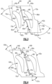
Figure 3 illustrates a radial view of two adjacentvane arc segments 60 from a midspan position along theairfoil sections 66 looking toward thefirst platforms 62. Although the examples herein are demonstrated with respect to thefirst platform 62, it is to be understood that the examples are also applicable to thesecond platform 64. Thefirst platform 62 includes axially leading and trailingfaces 62a/62b, and first and second circumferential faces 62c/62d that extend from theaxially trailing face 62b to theaxially leading face 62a. Theaxially leading face 62a is circumferentially offset from theaxially trailing face 62b (relative to engine central axis A, superimposed inFigure 3 ). The firstcircumferential face 62c of the first CMC vane arc segment 60 (left side inFigure 3 ) interfaces with the secondcircumferential face 62d of the second, adjacent CMC vane arc segment 60 (right side inFigure 3 ). Likewise, the firstcircumferential face 62c of the second CMC vane arc segment 60 (right side inFigure 3 ) will interface with thecircumferential face 62d of the next adjacent CMC vane arc segment (not shown). The term "interface" or variations thereof refers to the location where the faces meet, either in close proximity without contact or with contact. - The
vane arc segments 60 are formed of a ceramic matrix composite (CMC) 68. Referring to the cutaway section inFigure 2 , theCMC 68 includesceramic fibers 68a that are disposed in aceramic matrix 68b. TheCMC 68 may be, but is not limited to, a SiC/SiC composite in which SiC fibers are disposed within a SiC matrix. Theceramic fibers 68a are provided in fiber plies that may be woven or braided and may collectively include plies of different fiber weave configurations. For example, the fiber plies are continuous through at least thefirst platform 62, theairfoil section 66, and thesecond platform 64. - Gas turbine engine vanes can have many vibratory modes excited within the operating range of the engine. Many of the modes may be tuned via airfoil design to fall outside of the operating range, i.e., tuned out. However, it may not be feasible to tune out all modes, in which case external damping may be desired. To mitigate vibration, metallic vanes can utilize contact with mating hardware or local stiffening features that can be cast during investment casting. CMC vanes, however, have limited contact with mating hardware due structural and thermochemical considerations, and due to manufacturability challenges the addition of local tuning features is often unavailable. Thus, damping for CMC vanes presents a challenge. In this regard, the
vane arc segments 60 herein include at least onefriction damper 70 between the firstcircumferential face 62c of the first CMCvane arc segment 60 and the secondcircumferential face 62d of the second CMC vane arc segment. As thevane arc segments 60 vibrate and move relative to one another, thefriction damper 70 generates friction that serves to dissipate the kinetic vibrational energy as thermal energy. - In the illustrated example, each of the first and second circumferential faces 62c/62d has first and
second face sections 72a/72b that are generally parallel, circumferentially offset from each other, and joined by an angledfriction face section 72c that serves as thefriction damper 70. The angledfriction face section 72c of the firstcircumferential face 62c of the first CMC matrix vane arc segment 60 (on the left side) is in contact with the angledfriction face section 72c of the secondcircumferential face 62d of the second CMC matrix vane arc segment 60 (on the right side). That is, there is an interference fit between thevane arc segments 60 such that the angledfriction face sections 72c are in contact with each other when assembled in theengine 20. Each of thefriction face sections 72c are planar and thesections 72c are thus in areal contact. - In the example shown, the angled
friction face section 72c of the firstcircumferential face 62c is forward-facing, and the angledfriction face section 72c of the secondcircumferential face 62d is aft-facing. Thefriction face section 72c of the first circumferential face defines an angle (G1) with the engine central axis (A). The angle (G1) is the angle defined between the inside of the plane of thefriction face section 72c and the engine axis A. Thefriction face section 72c of the secondcircumferential face 62d likewise has an angle (G2) defined between the inside of its plane and the engine axis A. The angles G1 and G2 are substantially equal such that thefriction face sections 72c meet face-on-face when thevane arc segments 60 are assembled in theengine 20. The angles G1 and G2 and the amount of interference betweenfriction face sections 72c can be selected to adjust the damping effect, depending on airfoil design and estimated contact force. In one example, the amount of interference is determined based upon a "pretwist" angle, which is the angle between the platform datums and the airfoil datums. The pretwist angle can be adjusted to, in turn, adjust the amount of interference. The pretwist angle is often included within the total shroud angle of the damper surface relative to the airfoil reference datum. A useful range for the angles G1 and G2 is 10-80°, and in a further example the angles G1 and G2 are in the range 30-60°. Shallow angles toward the lower end of the range generate high contact force and may tend to cause thevane arc segments 60 to frictionally lock together, while steep angles toward the higher end of the range generate low contact force may tend reduce effectiveness. In this regard, it is expected that there will be an angular range over which damping is most effective. Given this disclosure, one of ordinary skill in the art will be able to perform design simulations to select the angles for a given design. -
Figure 4 illustrates additional examplevane arc segments 160, in which each of the first and second circumferential faces 62c/62d has first and second sets offriction dampers 70, each set being comprised of a mating pair of angledfriction face sections 72c with respective angles G1a/G1b/G2a/G2b. In general, G1a will be substantially equal to G2a, and G 1 b will be substantially equal to G2b. In a further example, the angles G1a/G1b/G2a/G2b are substantially equal to each other within the range disclosed herein above such that the contact forces are not more concentrated at one or the other of thefriction dampers 70. -
Figure 5 illustrates another example in whichvane arc segments 260 includefriction dampers 170. As shown, thefriction dampers 170 are bumpers that are comprised of protuberances that protrude from the firstcircumferential face 62c of theplatforms 62. In the illustrated example, the protuberances have a circular cross-section, but they could alternatively be polygonal, oval, or stadium in cross-sectional shape. Each bumper is continuous with theplatform 62. That is, each bumper is integrally formed with theplatform 62 such that there are no seams or mechanical attachments therebetween. The tip ends of the protuberances are in contact with the opposedcircumferential face 62d of the adjacentvane arc segment 260 such that, similar to the angledfriction face sections 72c, as thevane arc segments 260 vibrate and move relative to one another, the protuberances generate friction that serves to dissipate the kinetic vibrational energy as thermal energy. In that regard, the size, number, and contact area of the protuberances can be selected to adjust the damping effect. -
Figure 6 demonstrates an example of fabrication of the vane arc segment 60 (or alternatively 160 or 260). Thevane arc segment 60 is initially formed with anoversized platform 74. At a preform stage prior to consolidation with the matrix material, the oversized platform is cut or machined to the desired geometry of theplatform 62 to form the angledfriction face sections 72c (or protuberances). To the extent that cutting or machining thevane arc segment 60 prior to densification causes ragged fiber edges that are of concern, thesegment 60 can alternatively be formed after consolidation with the matrix material, although cutting or machining the CMC at that stage may be more time consuming. Theoversized platform 74 enables the angledfriction face sections 72c (or protuberances) to be applied to existing airfoil vane arc segment designs, whereby as long as an existing platform design fits within the footprint of theoversized platform 74, it can be re-designed to include the angledfriction face sections 72c (or protuberances). - Although a combination of features is shown in the illustrated examples, not all of them need to be combined to realize the benefits of various embodiments of this disclosure. In other words, a system designed according to an embodiment of this disclosure will not necessarily include all of the features shown in any one of the Figures or all of the portions schematically shown in the Figures. Moreover, selected features of one example embodiment may be combined with selected features of other example embodiments.
- The preceding description is exemplary rather than limiting in nature. Variations and modifications to the disclosed examples may become apparent to those skilled in the art that do not necessarily depart from this disclosure. The scope of legal protection given to this disclosure can only be determined by studying the following claims.
Claims (13)
- A gas turbine engine (20) comprising:
first and second ceramic matrix composite (CMC) vane arc segments (60; 160; 260) arranged about an engine central axis (A), each of the CMC vane arc segments (60; 160; 260) having a platform (62) and an airfoil section (66) extending off of the platform (62), the platform (62) defining an axially trailing face (62b), an axially leading face (62a) that is circumferentially offset from the axially trailing face (62b), and first and second circumferential faces (62c, 62d) extending from the axially trailing face (62b) to the axially leading face (62a), the first circumferential face (62c) of the first CMC vane arc segment (60; 160; 260) interfacing with the second circumferential face (62d) of the second CMC vane arc segment (60; 160; 260), and at least one friction damper (70; 170) between the first circumferential face (62c) of the first CMC vane arc segment (60; 160; 260) and the second circumferential face (62d) of the second CMC vane arc segment (60; 160; 260). - The gas turbine engine (20) as recited in claim 1, wherein each of the first and second circumferential faces (62c, 62d) has first and second face sections (72a, 72b) that are circumferentially offset from each other and joined by an angled friction face section (72c) serving as the at least one friction damper (70), the angled friction face section (72c) of the first circumferential face (62c) of the first CMC matrix vane arc segment (60; 160; 260) being in contact with the angled friction face section (72c) of the second circumferential face (62d) of the second CMC matrix vane arc segment (60; 160; 260).
- The gas turbine engine (20) as recited in claim 2, wherein the airfoil section (66) has a pressure and suction sides (66c, 66d), the first circumferential face (62c) is on the suction side of the platform (62), and the angled friction face section (72c) of the first circumferential face (62c) defines an angle (G1, G2) of 10-80° with the engine central axis (A).
- The gas turbine engine (20) as recited in claim 3, wherein the angle (G1, G2) is 30-60° with the engine central axis (A).
- The gas turbine engine (20) as recited in claim 2, 3 or 4, wherein the angled friction face section (72c) of the first circumferential face (62c) is forward-facing, and the angled friction face section (72c) of the second circumferential face (62d) is aft-facing.
- The gas turbine engine (20) as recited in any of claims 2 to 5, wherein relative movement between the first and second CMC vane arc segments (60; 160; 260) generates friction from the contact between the angled friction face section (72c) of the first circumferential face (62c) of the first CMC matrix vane arc segment (60; 160; 260) and the angled friction face section (72c) of the second circumferential face (62d) of the second CMC matrix vane arc segment (60; 160; 260).
- The gas turbine engine (20) as recited in any of claims 2 to 6, wherein each of the first and second circumferential faces (62c, 62d) has first and second sets of the first and second face sections (72a, 72b) and the angled friction face sections (72c).
- The gas turbine engine (20) as recited in claim 7, wherein the angled friction face section (72c) of the first set is adjacent the axially leading face (62a) and the angled friction face section (72c) of the second set is adjacent the axially trailing face (62b).
- The gas turbine engine (20) as recited in any of claims 2 to 8, wherein the angled friction face section (72c) is planar.
- The gas turbine engine (20) as recited in any preceding claim, wherein the at least one friction damper (70; 170) includes at least one bumper (170) protruding from the first circumferential face (62c), the at least one bumper (170) of the first CMC vane arc segment (60; 160; 260) contacting the second circumferential face (62d) of the second CMC vane arc segment (60; 160; 260).
- The gas turbine engine (20) as recited in claim 10, wherein the at least one bumper (170) is continuous with the platform (62).
- The gas turbine engine (20) as recited in claim 10 or 11, wherein the at least one bumper (170) comprises a protuberance.
- The gas turbine engine (20) as recited in any preceding claim, comprising:a compressor section (24);a combustor (56) in fluid communication with the compressor section (24); anda turbine section (28) in fluid communication with the combustor (56), the turbine section (28) including the first and second CMC vane arc segments (60; 160; 260).
Applications Claiming Priority (1)
| Application Number | Priority Date | Filing Date | Title |
|---|---|---|---|
| US18/455,308 US20250067189A1 (en) | 2023-08-24 | 2023-08-24 | Cmc vane arc segments with friction damper |
Publications (1)
| Publication Number | Publication Date |
|---|---|
| EP4513001A1 true EP4513001A1 (en) | 2025-02-26 |
Family
ID=92538453
Family Applications (1)
| Application Number | Title | Priority Date | Filing Date |
|---|---|---|---|
| EP24196285.1A Pending EP4513001A1 (en) | 2023-08-24 | 2024-08-23 | Gas turbine engine |
Country Status (2)
| Country | Link |
|---|---|
| US (1) | US20250067189A1 (en) |
| EP (1) | EP4513001A1 (en) |
Citations (2)
| Publication number | Priority date | Publication date | Assignee | Title |
|---|---|---|---|---|
| WO2011005337A1 (en) * | 2009-07-08 | 2011-01-13 | General Electric Company | Composite turbine nozzle segment |
| EP4234887A1 (en) * | 2022-02-28 | 2023-08-30 | Raytheon Technologies Corporation | Bifurcated fabric architecture for airfoils, methods of manufacture thereof and airfoils comprising the same |
Family Cites Families (4)
| Publication number | Priority date | Publication date | Assignee | Title |
|---|---|---|---|---|
| FR2970999B1 (en) * | 2011-02-02 | 2015-03-06 | Snecma | CURRENT TURBOMACHINE AUBES, MOBILE TURBOMACHINE WHEEL AND TURBOMACHINE COMPRISING THE SAME, AND PROCESS FOR THEIR MANUFACTURE |
| US9631500B2 (en) * | 2013-10-30 | 2017-04-25 | General Electric Company | Bucket assembly for use in a turbine engine |
| US11174739B2 (en) * | 2019-08-27 | 2021-11-16 | Solar Turbines Incorporated | Damped turbine blade assembly |
| US11092022B2 (en) * | 2019-11-04 | 2021-08-17 | Raytheon Technologies Corporation | Vane with chevron face |
-
2023
- 2023-08-24 US US18/455,308 patent/US20250067189A1/en active Pending
-
2024
- 2024-08-23 EP EP24196285.1A patent/EP4513001A1/en active Pending
Patent Citations (2)
| Publication number | Priority date | Publication date | Assignee | Title |
|---|---|---|---|---|
| WO2011005337A1 (en) * | 2009-07-08 | 2011-01-13 | General Electric Company | Composite turbine nozzle segment |
| EP4234887A1 (en) * | 2022-02-28 | 2023-08-30 | Raytheon Technologies Corporation | Bifurcated fabric architecture for airfoils, methods of manufacture thereof and airfoils comprising the same |
Also Published As
| Publication number | Publication date |
|---|---|
| US20250067189A1 (en) | 2025-02-27 |
Similar Documents
| Publication | Publication Date | Title |
|---|---|---|
| EP4086436A1 (en) | Gas turbine vane assembly | |
| EP3892822B1 (en) | Vane support system | |
| EP3971391A2 (en) | Cmc vane for a gas turbine engine with support and impingement baffle | |
| EP3219934A1 (en) | Seal assembly for gas turbine engine | |
| EP3812551B1 (en) | Vane with l-shaped seal | |
| EP4656842A2 (en) | Vane with chevron face | |
| EP3825516A1 (en) | Vane with collar | |
| EP3825518B1 (en) | Vane retention assembly | |
| EP3819474A1 (en) | Platform seal for a gas turbine engine | |
| EP3783195A1 (en) | Heatshield with damper member | |
| US20250067189A1 (en) | Cmc vane arc segments with friction damper | |
| EP4253726B1 (en) | Cmc vane mate face flanges with through-ply seal slots | |
| EP4283096A1 (en) | Cmc vane with flange having sloped radial face | |
| EP3808938B1 (en) | Airfoil component with trailing end margin and cutback | |
| EP3865669B1 (en) | Vane arc segment platform flange for a gas turbine engine with cap | |
| EP4617475A2 (en) | Variable thickness machinable coating for platform seals | |
| EP4530437A1 (en) | Cmc vane with detuned platform | |
| EP4435232A1 (en) | Gas turbine engine blade and method of making a gas turbine engine blade | |
| EP3333365B1 (en) | Stator with support structure feature for tuned airfoil | |
| EP4417788A1 (en) | Gas turbine engine blade and method of sizing a damper for a gas turbine engine blade | |
| EP3012412B1 (en) | Gas turbine engine and corresponding method for maintaining a multi-piece flow correcting vane. | |
| EP4520920A1 (en) | Tilted cmc vane arc segment | |
| US20260139600A1 (en) | Machinable coating for damping | |
| EP4080018B1 (en) | Vane arc segment with flange having step and method of fabricating a vane arc segment | |
| EP4056812A1 (en) | Chevron grooved mateface seal |
Legal Events
| Date | Code | Title | Description |
|---|---|---|---|
| PUAI | Public reference made under article 153(3) epc to a published international application that has entered the european phase |
Free format text: ORIGINAL CODE: 0009012 |
|
| STAA | Information on the status of an ep patent application or granted ep patent |
Free format text: STATUS: THE APPLICATION HAS BEEN PUBLISHED |
|
| AK | Designated contracting states |
Kind code of ref document: A1 Designated state(s): AL AT BE BG CH CY CZ DE DK EE ES FI FR GB GR HR HU IE IS IT LI LT LU LV MC ME MK MT NL NO PL PT RO RS SE SI SK SM TR |
|
| STAA | Information on the status of an ep patent application or granted ep patent |
Free format text: STATUS: REQUEST FOR EXAMINATION WAS MADE |
|
| 17P | Request for examination filed |
Effective date: 20250826 |
|
| STAA | Information on the status of an ep patent application or granted ep patent |
Free format text: STATUS: EXAMINATION IS IN PROGRESS |
|
| 17Q | First examination report despatched |
Effective date: 20260206 |