EP4512999A1 - Turbine rotor dovetail structure with splines - Google Patents
Turbine rotor dovetail structure with splines Download PDFInfo
- Publication number
- EP4512999A1 EP4512999A1 EP24195252.2A EP24195252A EP4512999A1 EP 4512999 A1 EP4512999 A1 EP 4512999A1 EP 24195252 A EP24195252 A EP 24195252A EP 4512999 A1 EP4512999 A1 EP 4512999A1
- Authority
- EP
- European Patent Office
- Prior art keywords
- radially outwardly
- disc
- leading
- outwardly facing
- facing surface
- Prior art date
- Legal status (The legal status is an assumption and is not a legal conclusion. Google has not performed a legal analysis and makes no representation as to the accuracy of the status listed.)
- Pending
Links
Images

Classifications
-
- F—MECHANICAL ENGINEERING; LIGHTING; HEATING; WEAPONS; BLASTING
- F01—MACHINES OR ENGINES IN GENERAL; ENGINE PLANTS IN GENERAL; STEAM ENGINES
- F01D—NON-POSITIVE DISPLACEMENT MACHINES OR ENGINES, e.g. STEAM TURBINES
- F01D5/00—Blades; Blade-carrying members; Heating, heat-insulating, cooling or antivibration means on the blades or the members
- F01D5/34—Rotor-blade aggregates of unitary construction, e.g. formed of sheet laminae
-
- F—MECHANICAL ENGINEERING; LIGHTING; HEATING; WEAPONS; BLASTING
- F01—MACHINES OR ENGINES IN GENERAL; ENGINE PLANTS IN GENERAL; STEAM ENGINES
- F01D—NON-POSITIVE DISPLACEMENT MACHINES OR ENGINES, e.g. STEAM TURBINES
- F01D5/00—Blades; Blade-carrying members; Heating, heat-insulating, cooling or antivibration means on the blades or the members
- F01D5/12—Blades
- F01D5/14—Form or construction
- F01D5/141—Shape, i.e. outer, aerodynamic form
- F01D5/142—Shape, i.e. outer, aerodynamic form of the blades of successive rotor or stator blade-rows
- F01D5/143—Contour of the outer or inner working fluid flow path wall, i.e. shroud or hub contour
-
- F—MECHANICAL ENGINEERING; LIGHTING; HEATING; WEAPONS; BLASTING
- F01—MACHINES OR ENGINES IN GENERAL; ENGINE PLANTS IN GENERAL; STEAM ENGINES
- F01D—NON-POSITIVE DISPLACEMENT MACHINES OR ENGINES, e.g. STEAM TURBINES
- F01D5/00—Blades; Blade-carrying members; Heating, heat-insulating, cooling or antivibration means on the blades or the members
- F01D5/12—Blades
- F01D5/14—Form or construction
- F01D5/141—Shape, i.e. outer, aerodynamic form
- F01D5/145—Means for influencing boundary layers or secondary circulations
-
- F—MECHANICAL ENGINEERING; LIGHTING; HEATING; WEAPONS; BLASTING
- F05—INDEXING SCHEMES RELATING TO ENGINES OR PUMPS IN VARIOUS SUBCLASSES OF CLASSES F01-F04
- F05D—INDEXING SCHEME FOR ASPECTS RELATING TO NON-POSITIVE-DISPLACEMENT MACHINES OR ENGINES, GAS-TURBINES OR JET-PROPULSION PLANTS
- F05D2240/00—Components
- F05D2240/20—Rotors
- F05D2240/24—Rotors for turbines
-
- F—MECHANICAL ENGINEERING; LIGHTING; HEATING; WEAPONS; BLASTING
- F05—INDEXING SCHEMES RELATING TO ENGINES OR PUMPS IN VARIOUS SUBCLASSES OF CLASSES F01-F04
- F05D—INDEXING SCHEME FOR ASPECTS RELATING TO NON-POSITIVE-DISPLACEMENT MACHINES OR ENGINES, GAS-TURBINES OR JET-PROPULSION PLANTS
- F05D2240/00—Components
- F05D2240/80—Platforms for stationary or moving blades
-
- F—MECHANICAL ENGINEERING; LIGHTING; HEATING; WEAPONS; BLASTING
- F05—INDEXING SCHEMES RELATING TO ENGINES OR PUMPS IN VARIOUS SUBCLASSES OF CLASSES F01-F04
- F05D—INDEXING SCHEME FOR ASPECTS RELATING TO NON-POSITIVE-DISPLACEMENT MACHINES OR ENGINES, GAS-TURBINES OR JET-PROPULSION PLANTS
- F05D2250/00—Geometry
- F05D2250/70—Shape
- F05D2250/71—Shape curved
-
- F—MECHANICAL ENGINEERING; LIGHTING; HEATING; WEAPONS; BLASTING
- F05—INDEXING SCHEMES RELATING TO ENGINES OR PUMPS IN VARIOUS SUBCLASSES OF CLASSES F01-F04
- F05D—INDEXING SCHEME FOR ASPECTS RELATING TO NON-POSITIVE-DISPLACEMENT MACHINES OR ENGINES, GAS-TURBINES OR JET-PROPULSION PLANTS
- F05D2250/00—Geometry
- F05D2250/70—Shape
- F05D2250/71—Shape curved
- F05D2250/711—Shape curved convex
-
- F—MECHANICAL ENGINEERING; LIGHTING; HEATING; WEAPONS; BLASTING
- F05—INDEXING SCHEMES RELATING TO ENGINES OR PUMPS IN VARIOUS SUBCLASSES OF CLASSES F01-F04
- F05D—INDEXING SCHEME FOR ASPECTS RELATING TO NON-POSITIVE-DISPLACEMENT MACHINES OR ENGINES, GAS-TURBINES OR JET-PROPULSION PLANTS
- F05D2250/00—Geometry
- F05D2250/70—Shape
- F05D2250/71—Shape curved
- F05D2250/712—Shape curved concave
Definitions
- the present disclosure relates to turbine engine and, more particularly, to a turbine engine with an integrated blade rotor (IBR) in a high-temperature turbine region.
- IBR integrated blade rotor
- an integrated blade rotor includes a disc, blades integrally formed with the disc and radially outwardly facing surfaces of the disc. Each radially outwardly facing surface is disposed adjacent to a corresponding blade and includes a curved profile.
- a height of the curved profile is about 1/3 a width of the disc.
- each blade has an airfoil shape and includes leading and trailing edges and pressure and suction surfaces respectively extending between the leading and trailing edges.
- each radially outwardly facing surface is adjacent to the pressure surface of the corresponding blade.
- each radially outwardly facing surface has a concave profile in a circumferential dimension (or direction) about the disc.
- each radially outwardly facing surface blends tangentially with the leading and trailing edges.
- a height the curved profile protrudes from the cylindrical plane is about 1/3 a width of the disc.
- each blade has an airfoil shape and includes leading and trailing edges and pressure and suction surfaces respectively extending between the leading and trailing edges.
- each radially outwardly facing surface blends tangentially with the leading and trailing edges.
- each radially outwardly facing surface includes a leading edge portion that blends tangentially with a leading edge fillet at a base of the leading edge and a trailing edge portion that blends tangentially with a trailing edge fillet at a base of the trailing edge.
- a gas turbine engine includes a turbine section in which high-temperature fluid is expanded to generate work and an IBR.
- the IBR is operably disposed in the turbine section whereby the blades aerodynamically interact with the high-temperature fluid and each radially outwardly facing surface is exposed to a hot gas path.
- each radially outwardly facing surface is adjacent to a pressure surface of the corresponding blade and has a concave profile in a circumferential dimension about the disc.
- each radially outwardly facing surface includes a leading edge portion that blends tangentially with a leading edge fillet at a base of a leading edge of the corresponding blade and a trailing edge portion that blends tangentially with a trailing edge fillet at a base of a trailing edge of the corresponding blade.
- a gas turbine engine includes a turbine section in which high-temperature fluid is expanded to generate work and an IBR.
- the IBR is operably disposed in the turbine section whereby the blades aerodynamically interact with the high-temperature fluid and each radially outwardly facing surface is exposed to a hot gas path.
- FIG. 1 schematically illustrates a gas turbine engine 20.
- the gas turbine engine 20 is disclosed herein as a two-spool turbofan that generally incorporates a fan section 22, a compressor section 24, a combustor section 26 and a turbine section 28.
- Alternative engines might include other systems or features.
- the fan section 22 drives air along a bypass flow path B in a bypass duct, while the compressor section 24 drives air along a core flow path C for compression and communication into the combustor section 26 then expansion through the turbine section 28.
- FIG. 1 schematically illustrates a gas turbine engine 20.
- the gas turbine engine 20 is disclosed herein as a two-spool turbofan that generally incorporates a fan section 22, a compressor section 24, a combustor section 26 and a turbine section 28.
- Alternative engines might include other systems or features.
- the fan section 22 drives air along a bypass flow path B in a bypass duct
- the compressor section 24 drives air along a core flow path C for compression and communication into the combustor section 26
- the exemplary engine 20 generally includes a low speed spool 30 and a high speed spool 32 mounted for rotation about an engine central longitudinal axis A relative to an engine static structure 36 via several bearing systems 38. It should be understood that various bearing systems 38 at various locations may alternatively or additionally be provided, and the location of bearing systems 38 may be varied as appropriate to the application.
- the low speed spool 30 generally includes an inner shaft 40 that interconnects a fan 42, a low pressure compressor 44 and a low pressure turbine 46.
- the inner shaft 40 is connected to the fan 42 through a speed change mechanism, which in exemplary gas turbine engine 20 is illustrated as a geared architecture 48 to drive the fan 42 at a lower speed than the low speed spool 30.
- the high speed spool 32 includes an outer shaft 50 that interconnects a high pressure compressor 52 and high pressure turbine 54.
- a combustor 56 is arranged in exemplary gas turbine 20 between the high pressure compressor 52 and the high pressure turbine 54.
- An engine static structure 36 is arranged generally between the high pressure turbine 54 and the low pressure turbine 46.
- the engine static structure 36 further supports bearing systems 38 in the turbine section 28.
- the inner shaft 40 and the outer shaft 50 are concentric and rotate via bearing systems 38 about the engine central longitudinal axis A which is collinear with their longitudinal axes.
- each of the positions of the fan section 22, compressor section 24, combustor section 26, turbine section 28, and fan drive gear system 48 may be varied.
- gear system 48 may be located aft of combustor section 26 or even aft of turbine section 28, and fan section 22 may be positioned forward or aft of the location of gear system 48.
- the compressor can be regarded as a low-temperature region and includes integrated blade rotors (IBRs) whereas the turbine can be regarded as a high-temperature region and includes rotor discs in which blades can be disconnected from a disc.
- IBRs of the compressor are rotational features characterized in that blades are integrally formed with a rotor element.
- the use of IBRs in turbines or other high-temperature regions as a replacement for rotor discs may improve manufacturability and reliability but has been found to result in high stress levels on the blades. These high stress levels are mainly concentrated at the leading and trailing edges of the blades and are caused by centrifugal forces combined with hot gas exposure.
- an IBR is provided for use in a high-temperature region of a turbine, such as a gas turbine engine.
- the IBR can be machined and includes a central portion or disc, blades integrally formed with the disc and surfaces between the blades in a circumferential direction. These surfaces are exposed to the hot gas path of the turbine and are characterized as having a cylindrical, curved and/or convex profile to minimize flow separation.
- the convex profile blends tangentially with cylindrical sections of the disc and, in particular, can be about 1/3 a width of the disc with reference to imaginary lines passing through leading and trailing edge radii.
- an IBR 201 is provided and includes a disc 210, blades 220 that are integrally formed with the disc 210 and radially outwardly facing surfaces 230 of the disc 210.
- the disc 210 has a generally annular shape, opposite axial sides 211, 212 and a width W in the axial dimension D between the axial sides 211, 212.
- the radially outwardly facing surfaces 230 are provided at a periphery 213 of the disc 210.
- the blades 220 are arranged in a circumferential dimension C about the disc 210 and extend radially outwardly in a radial dimension R.
- Each blade 220 can have an airfoil shape with a leading edge 221, a trailing edge 222 opposite the leading edge 221, a pressure surface 223 extending from the leading edge 221 to the trailing edge 222, a suction surface 224, which is opposite the pressure surface 223 and which extends from the leading edge 221 to the trailing edge 222, and a blade tip 225.
- Each radially outwardly facing surface 230 is disposed adjacent to a pressure surface 223 of a corresponding blade 220 and extends in the circumferential dimension C to a suction surface 224 of a neighboring blade 220.
- the IBR 201 can be formed from an initial block of material, such as metallic material or polymeric material for example, which is forged or machined.
- Each radially outwardly facing surface 230 includes leading and trailing wing sections 231, 232.
- the leading and trailing wing sections 231, 232 have shared upper surfaces 233 and shared lower surfaces 234.
- the upper surfaces 233 of the leading and trailing wing sections 231, 232 cooperatively define a cylindrical plane CP about the periphery 213 of the disc 210.
- the corresponding blade 220 for each radially outwardly facing surface 230 extends radially outwardly from this cylindrical plane CP.
- the lower surfaces 234 of the leading and trailing wing sections 231, 232 curvilinearly taper toward the opposite axial sides 211, 212 of the disc 210.
- the leading and trailing wing sections 231, 232 extend axially beyond the leading and trailing edges 221, 222 of the corresponding blade 220.
- Each radially outwardly facing surface 230 further includes a primary curved profile 235 (see FIG. 3 ) and a secondary curved profile 236 (see FIG. 2 ).
- the primary curved profile 235 protrudes radially outwardly from the cylindrical plane CP along a chord length L of the corresponding blade 220.
- a maximum height H that the curved profile 235 protrudes from the cylindrical plane CP is about 1/3 of the width W of the disc 210.
- the secondary curved profile 236 is a concave profile that extends in the circumferential dimension C between the pressure surface 223 of the corresponding blade 220 and the suction surface 224 of the neighboring blade 220.
- each radially outwardly facing surface 230 has a leading edge portion 237, a trailing edge portion 238 and a central portion 239 which is axially interposed between the leading edge portion 237 and the trailing edge portion 238 (the leading edge portion 237 is shown in FIG. 4A and the trailing edge portion 238 is shown in FIG. 4B ).
- the leading edge portion 237, the trailing edge portion 238 and the central portion 239 cooperatively form the primary curved profile 235.
- the leading edge portion 237 corresponds to the lead edge 221 of the corresponding blade 220 and blends tangentially with a leading edge fillet 2210 at a base of the leading edge 221 of the corresponding blade 220. That is, at the base of the leading edge 221, the leading edge fillet 2210 has a curvature 401 with a uniform or changing radius of curvature from the upper surface 233 of the leading wing section 231 and the leading edge portion 237 is formed to extend tangentially from this curvature 401.
- the trailing edge portion 238 blends tangentially with a trailing edge fillet 2220 at a base of the trailing edge 222 of the corresponding blade 220.
- the trailing edge fillet 2220 has a curvature 402 with a uniform or changing radius of curvature from the upper surface 233 of the trailing wing section 232 and the leading edge portion 238 is formed to extend tangentially from this curvature 402.
- a curvature of the leading edge portion 237 (which is initially similar to the curvature 401 of the leading edge fillet 2210 allowing for the tangential blending) increases and then reverses direction whereupon the leading edge portion 237 connects with the central portion 239.
- a curvature of the trailing edge portion 238 (which is initially similar to the curvature 402 of the trailing edge fillet 2220 allowing for the tangential blending) increases and then reverses direction whereupon the trailing edge portion 238 connects with the central portion 239.
- the IBR 201 can be provided, for example, in the turbine section 28 of the gas turbine engine 20. As shown in FIG. 5 , the blades 220 are positioned to aerodynamically interact with the high-temperature fluid flowing through the turbine section 28 and each radially outwardly facing surface 220 is thus exposed to a hot gas path.
Landscapes
- Engineering & Computer Science (AREA)
- Physics & Mathematics (AREA)
- Fluid Mechanics (AREA)
- Mechanical Engineering (AREA)
- General Engineering & Computer Science (AREA)
- Ceramic Engineering (AREA)
- Turbine Rotor Nozzle Sealing (AREA)
Abstract
An integrated blade rotor is provided and includes a disc (210), blades (220) integrally formed with the disc (210) and radially outwardly facing surfaces (230) of the disc (210). Each radially outwardly facing surface (230) is disposed adjacent to a corresponding blade (220) and includes a curved profile (235).
Description
- The present disclosure relates to turbine engine and, more particularly, to a turbine engine with an integrated blade rotor (IBR) in a high-temperature turbine region.
- In turbine engines, a turbine is used to generate power for propulsion, in some cases, by turning propellers, fans or helicopter blades through a gearbox. In some instances, the gearbox output is used to power electrical generators. In a gas turbine engine, fuel and compressed oxygen are combusted in a combustor to produce a high-temperature and high-pressure fluid. This fluid enters a turbine and interacts with rows or stages of turbine blades and vanes. This interaction causes the stages of turbine blades to rotate a rotor. The rotor rotation drives a compressor to compress the oxygen for the combustor and, as noted above, can be used to drive operations of a generator to produce electricity or for propulsion.
- According to an aspect of the present invention, an integrated blade rotor (IBR) is provided and includes a disc, blades integrally formed with the disc and radially outwardly facing surfaces of the disc. Each radially outwardly facing surface is disposed adjacent to a corresponding blade and includes a curved profile.
- In an embodiment of the above, a height of the curved profile is about 1/3 a width of the disc.
- In an embodiment according to any of the previous embodiments, each blade has an airfoil shape and includes leading and trailing edges and pressure and suction surfaces respectively extending between the leading and trailing edges.
- In an embodiment according to any of the previous embodiments, each radially outwardly facing surface is adjacent to the pressure surface of the corresponding blade.
- In an embodiment according to any of the previous embodiments, each radially outwardly facing surface has a concave profile in a circumferential dimension (or direction) about the disc.
- In an embodiment according to any of the previous embodiments, each radially outwardly facing surface blends tangentially with the leading and trailing edges.
- In an embodiment according to any of the previous embodiments, each radially outwardly facing surface includes a leading edge portion that blends tangentially with a leading edge fillet at a base of the leading edge and a trailing edge portion that blends tangentially with a trailing edge fillet at a base of the trailing edge.
- According to an aspect of the present invention, a gas turbine engine is provided and includes a turbine section in which high-temperature fluid is expanded to generate work and an IBR. The IBR is operably disposed in the turbine section whereby the blades aerodynamically interact with the high-temperature fluid and each radially outwardly facing surface is exposed to a hot gas path.
- According to an aspect of the present invention, an integrated blade rotor (IBR) is provided and includes a disc, blades integrally formed with the disc and radially outwardly facing surfaces of the disc. Each radially outwardly facing surface is disposed adjacent to a corresponding blade and includes leading and trailing wing sections that cooperatively define a cylindrical plane about the disc from which the corresponding blade extends radially outwardly and a curved profile which protrudes radially outwardly from the cylindrical plane along a chord length of the corresponding blade.
- In an embodiment of the above, a height the curved profile protrudes from the cylindrical plane is about 1/3 a width of the disc.
- In an embodiment according to any of the previous embodiments, each blade has an airfoil shape and includes leading and trailing edges and pressure and suction surfaces respectively extending between the leading and trailing edges.
- In an embodiment according to any of the previous embodiments, each radially outwardly facing surface is adjacent to the pressure surface of the corresponding blade.
- In an embodiment according to any of the previous embodiments, each radially outwardly facing surface has a concave profile in a circumferential dimension about the disc.
- In an embodiment according to any of the previous embodiments, each radially outwardly facing surface blends tangentially with the leading and trailing edges.
- In an embodiment according to any of the previous embodiments, each radially outwardly facing surface includes a leading edge portion that blends tangentially with a leading edge fillet at a base of the leading edge and a trailing edge portion that blends tangentially with a trailing edge fillet at a base of the trailing edge.
- According to an aspect of the present invention, a gas turbine engine is provided and includes a turbine section in which high-temperature fluid is expanded to generate work and an IBR. The IBR is operably disposed in the turbine section whereby the blades aerodynamically interact with the high-temperature fluid and each radially outwardly facing surface is exposed to a hot gas path.
- According to an aspect of the present invention, an integrated blade rotor (IBR) is provided and includes a disc, blades integrally formed with the disc and radially outwardly facing surfaces of the disc. Each radially outwardly facing surface is disposed adjacent to a corresponding blade and includes leading and trailing wing sections that protrude fore and aft of the corresponding blade, outboard surfaces of the leading and trailing wing sections cooperatively defining a cylindrical plane about the disc from which the corresponding blade extends radially outwardly, inboard surfaces of the leading and trailing wing sections curving fore and aft from opposite sides of the disc and a curved profile which protrudes radially outwardly from the cylindrical plane along a chord length of the corresponding blade to a height which is about 1/3 a width of the disc.
- In an embodiment of the above, each radially outwardly facing surface is adjacent to a pressure surface of the corresponding blade and has a concave profile in a circumferential dimension about the disc.
- In an embodiment according to any of the previous embodiments, each radially outwardly facing surface includes a leading edge portion that blends tangentially with a leading edge fillet at a base of a leading edge of the corresponding blade and a trailing edge portion that blends tangentially with a trailing edge fillet at a base of a trailing edge of the corresponding blade.
- According to an aspect of the present invention, a gas turbine engine is provided and includes a turbine section in which high-temperature fluid is expanded to generate work and an IBR. The IBR is operably disposed in the turbine section whereby the blades aerodynamically interact with the high-temperature fluid and each radially outwardly facing surface is exposed to a hot gas path.
- Additional features and advantages are realized through the techniques of the present disclosure. Other embodiments and aspects of the disclosure are described in detail herein and are considered a part of the claimed technical concept. For a better understanding of the disclosure with the advantages and the features, refer to the description and to the drawings.
- For a more complete understanding of this disclosure, reference is now made to the following brief description, taken in connection with the accompanying drawings and detailed description, wherein like reference numerals represent like parts:
-
FIG. 1 is a partial cross-sectional view of a portion of an exemplary gas turbine engine in accordance with embodiments; -
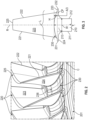
FIG. 2 is a perspective view of an integrated blade rotor (IBR) in accordance with embodiments; -
FIG. 3 is a side view of an IBR in accordance with embodiments; -
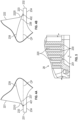
FIG. 4A is an enlarged side view of a leading edge portion of a curved profile of a surface of an IBR in accordance with embodiments; -
FIG. 4B is an enlarged side view of a trailing edge portion of a curved profile of a surface of an IBR in accordance with embodiments; and -
FIG. 5 is an enlarged side view of a turbine section of the gas turbine engine ofFIG. 1 with IBRs installed therein in accordance with embodiments. -
FIG. 1 schematically illustrates agas turbine engine 20. Thegas turbine engine 20 is disclosed herein as a two-spool turbofan that generally incorporates afan section 22, acompressor section 24, acombustor section 26 and aturbine section 28. Alternative engines might include other systems or features. Thefan section 22 drives air along a bypass flow path B in a bypass duct, while thecompressor section 24 drives air along a core flow path C for compression and communication into thecombustor section 26 then expansion through theturbine section 28. Although depicted as a two-spool turbofan gas turbine engine in the disclosed non-limiting embodiment, it should be understood that the concepts described herein are not limited to use with two-spool turbofans as the teachings may be applied to other types of turbine engines including three-spool architectures. - The
exemplary engine 20 generally includes alow speed spool 30 and ahigh speed spool 32 mounted for rotation about an engine central longitudinal axis A relative to an enginestatic structure 36 viaseveral bearing systems 38. It should be understood thatvarious bearing systems 38 at various locations may alternatively or additionally be provided, and the location ofbearing systems 38 may be varied as appropriate to the application. - The
low speed spool 30 generally includes aninner shaft 40 that interconnects afan 42, alow pressure compressor 44 and alow pressure turbine 46. Theinner shaft 40 is connected to thefan 42 through a speed change mechanism, which in exemplarygas turbine engine 20 is illustrated as a gearedarchitecture 48 to drive thefan 42 at a lower speed than thelow speed spool 30. Thehigh speed spool 32 includes anouter shaft 50 that interconnects ahigh pressure compressor 52 andhigh pressure turbine 54. Acombustor 56 is arranged inexemplary gas turbine 20 between thehigh pressure compressor 52 and thehigh pressure turbine 54. An enginestatic structure 36 is arranged generally between thehigh pressure turbine 54 and thelow pressure turbine 46. The enginestatic structure 36 further supports bearingsystems 38 in theturbine section 28. Theinner shaft 40 and theouter shaft 50 are concentric and rotate viabearing systems 38 about the engine central longitudinal axis A which is collinear with their longitudinal axes. - The core airflow is compressed by the
low pressure compressor 44 then thehigh pressure compressor 52, mixed and burned with fuel in thecombustor 56, then expanded over thehigh pressure turbine 54 andlow pressure turbine 46. Theturbines low speed spool 30 andhigh speed spool 32 in response to the expansion. It will be appreciated that each of the positions of thefan section 22,compressor section 24,combustor section 26,turbine section 28, and fandrive gear system 48 may be varied. For example,gear system 48 may be located aft ofcombustor section 26 or even aft ofturbine section 28, andfan section 22 may be positioned forward or aft of the location ofgear system 48. - In typical gas turbine engines, such as the
gas turbine engine 20 ofFIG. 1 , the compressor can be regarded as a low-temperature region and includes integrated blade rotors (IBRs) whereas the turbine can be regarded as a high-temperature region and includes rotor discs in which blades can be disconnected from a disc. The IBRs of the compressor are rotational features characterized in that blades are integrally formed with a rotor element. The use of IBRs in turbines or other high-temperature regions as a replacement for rotor discs may improve manufacturability and reliability but has been found to result in high stress levels on the blades. These high stress levels are mainly concentrated at the leading and trailing edges of the blades and are caused by centrifugal forces combined with hot gas exposure. - Therefore, a need exists for an improved IBR design for a turbine-compatible IBR that does not result in high stress levels on the leading and trailing edges of the blades.
- Thus, as will be discussed below, an IBR is provided for use in a high-temperature region of a turbine, such as a gas turbine engine. The IBR can be machined and includes a central portion or disc, blades integrally formed with the disc and surfaces between the blades in a circumferential direction. These surfaces are exposed to the hot gas path of the turbine and are characterized as having a cylindrical, curved and/or convex profile to minimize flow separation. The convex profile blends tangentially with cylindrical sections of the disc and, in particular, can be about 1/3 a width of the disc with reference to imaginary lines passing through leading and trailing edge radii.
- With reference to
FIGS. 2 and 3 , anIBR 201 is provided and includes adisc 210,blades 220 that are integrally formed with thedisc 210 and radially outwardly facingsurfaces 230 of thedisc 210. Thedisc 210 has a generally annular shape, oppositeaxial sides axial sides surfaces 230 are provided at aperiphery 213 of thedisc 210. Theblades 220 are arranged in a circumferential dimension C about thedisc 210 and extend radially outwardly in a radial dimension R. Eachblade 220 can have an airfoil shape with aleading edge 221, a trailingedge 222 opposite theleading edge 221, apressure surface 223 extending from theleading edge 221 to the trailingedge 222, asuction surface 224, which is opposite thepressure surface 223 and which extends from theleading edge 221 to the trailingedge 222, and ablade tip 225. Each radially outwardly facingsurface 230 is disposed adjacent to apressure surface 223 of acorresponding blade 220 and extends in the circumferential dimension C to asuction surface 224 of aneighboring blade 220. - The
IBR 201 can be formed from an initial block of material, such as metallic material or polymeric material for example, which is forged or machined. - Each radially outwardly facing
surface 230 includes leading and trailingwing sections wing sections upper surfaces 233 and sharedlower surfaces 234. Theupper surfaces 233 of the leading and trailingwing sections periphery 213 of thedisc 210. Thecorresponding blade 220 for each radially outwardly facingsurface 230 extends radially outwardly from this cylindrical plane CP. Thelower surfaces 234 of the leading and trailingwing sections axial sides disc 210. The leading and trailingwing sections edges corresponding blade 220. - Each radially outwardly facing
surface 230 further includes a primary curved profile 235 (seeFIG. 3 ) and a secondary curved profile 236 (seeFIG. 2 ). The primarycurved profile 235 protrudes radially outwardly from the cylindrical plane CP along a chord length L of thecorresponding blade 220. In accordance with embodiments, a maximum height H that thecurved profile 235 protrudes from the cylindrical plane CP is about 1/3 of the width W of thedisc 210. The secondarycurved profile 236 is a concave profile that extends in the circumferential dimension C between thepressure surface 223 of thecorresponding blade 220 and thesuction surface 224 of the neighboringblade 220. - With continued reference to
FIG. 3 and with additional reference toFIGS. 4A and 4B , each radially outwardly facingsurface 230 has aleading edge portion 237, a trailingedge portion 238 and acentral portion 239 which is axially interposed between theleading edge portion 237 and the trailing edge portion 238 (theleading edge portion 237 is shown inFIG. 4A and the trailingedge portion 238 is shown inFIG. 4B ). Theleading edge portion 237, the trailingedge portion 238 and thecentral portion 239 cooperatively form the primarycurved profile 235. - As shown in
FIG. 4A , the leadingedge portion 237 corresponds to thelead edge 221 of thecorresponding blade 220 and blends tangentially with aleading edge fillet 2210 at a base of theleading edge 221 of thecorresponding blade 220. That is, at the base of theleading edge 221, the leadingedge fillet 2210 has acurvature 401 with a uniform or changing radius of curvature from theupper surface 233 of the leadingwing section 231 and theleading edge portion 237 is formed to extend tangentially from thiscurvature 401. The trailingedge portion 238 blends tangentially with a trailingedge fillet 2220 at a base of the trailingedge 222 of thecorresponding blade 220. That is, at the base of the trailingedge 222, the trailingedge fillet 2220 has acurvature 402 with a uniform or changing radius of curvature from theupper surface 233 of the trailingwing section 232 and theleading edge portion 238 is formed to extend tangentially from thiscurvature 402. - With increasing axial distance from the
leading edge 221 of thecorresponding blade 220, a curvature of the leading edge portion 237 (which is initially similar to thecurvature 401 of theleading edge fillet 2210 allowing for the tangential blending) increases and then reverses direction whereupon theleading edge portion 237 connects with thecentral portion 239. With increasing axial distance from the trailingedge 222 of thecorresponding blade 220, a curvature of the trailing edge portion 238 (which is initially similar to thecurvature 402 of the trailingedge fillet 2220 allowing for the tangential blending) increases and then reverses direction whereupon the trailingedge portion 238 connects with thecentral portion 239. - With continued reference to
FIGS. 2, 3 ,4A and 4B , with reference back toFIG. 1 and with additional reference toFIG. 5 , theIBR 201 can be provided, for example, in theturbine section 28 of thegas turbine engine 20. As shown inFIG. 5 , theblades 220 are positioned to aerodynamically interact with the high-temperature fluid flowing through theturbine section 28 and each radially outwardly facingsurface 220 is thus exposed to a hot gas path. - Technical effects and benefits of the present disclosure are the provision of an IBR for use with a high-temperature region of a turbine. The surfaces of the IBR between the blades, which are exposed to the hot gas path of the turbine, are characterized as having a cylindrical, curved and/or convex profile to minimize flow separation. This leads to eliminations or reductions of high stress levels on the leading and trailing edges of the blades.
- The corresponding structures, materials, acts, and equivalents of all means or step plus function elements in the claims below are intended to include any structure, material, or act for performing the function in combination with other claimed elements as specifically claimed. The description of the present disclosure has been presented for purposes of illustration and description, but is not intended to be exhaustive or limited to the technical concepts in the form disclosed. Many modifications and variations will be apparent to those of ordinary skill in the art without departing from the scope and spirit of the disclosure. The embodiments were chosen and described in order to best explain the principles of the disclosure and the practical application, and to enable others of ordinary skill in the art to understand the disclosure for various embodiments with various modifications as are suited to the particular use contemplated.
- While the preferred embodiments to the disclosure have been described, it will be understood that those skilled in the art, both now and in the future, may make various improvements and enhancements which fall within the scope of the claims which follow. These claims should be construed to maintain the proper protection for the disclosure first described.
Claims (10)
- An integrated blade rotor, comprising:a disc (210);blades (220) integrally formed with the disc (210); andradially outwardly facing surfaces (230) of the disc (210), each radially outwardly facing surface (230) being disposed adjacent to a corresponding blade (220) and comprising a curved profile (235).
- The integrated blade rotor according to claim 1, wherein a height (H) of the curved profile (235) is about 1/3 of a width (W) of the disc (210).
- The integrated blade rotor according to claim 1 or 2, wherein each blade (220) has an airfoil shape and comprises:leading and trailing edges (221, 222); andpressure and suction surfaces (223,224) respectively extending between the leading and trailing edges (221, 222).
- The integrated blade rotor according to claim 3, wherein each radially outwardly facing surface (230) is adjacent to the pressure surface (223) of the corresponding blade (220).
- The integrated blade rotor according to claim 3 or 4, wherein each radially outwardly facing surface (230) blends tangentially with the leading and trailing edges (221, 222).
- The integrated blade rotor according to claim 3, 4 or 5, wherein each radially outwardly facing surface (230) comprises:a leading edge portion (237) that blends tangentially with a leading edge fillet (2210) at a base of the leading edge (221) of the corresponding blade (220); anda trailing edge portion that blends tangentially with a trailing edge fillet (2220) at a base of the trailing edge (222) of the corresponding blade (220).
- The integrated blade rotor according to any preceding claim, wherein each radially outwardly facing surface (230) has a concave profile in a circumferential dimension about the disc (210).
- The integrated blade rotor of any preceding claim, each radially outwardly facing surface (230) comprising leading and trailing wing sections (231, 232) that cooperatively define a cylindrical plane about the disc (210) from which the corresponding blade (220) extends radially outwardly, wherein the curved profile (235) protrudes radially outwardly from the cylindrical plane along a chord length (L) of the corresponding blade (220).
- The integrated blade rotor of any preceding claim, each radially outwardly facing surface (230) comprising a or the leading and trailing wing sections (231, 232) that protrude fore and aft of the corresponding blade (220), wherein:outboard surfaces of the leading and trailing wing sections (231, 232) cooperatively define a or the cylindrical plane about the disc (210) from which the corresponding blade (220) extends radially outwardly; andinboard surfaces of the leading and trailing wing sections (231, 232) curve fore and aft from opposite sides of the disc (210), wherein the curved profile (235) protrudes radially outwardly from the cylindrical plane along a chord length (L) of the corresponding blade (220) to a height (H) which is about 1/3 of a width (W) of the disc (210).
- A gas turbine engine, comprising:a turbine section (28) in which high-temperature fluid is expanded to generate work; andthe integrated blade rotor (201) of any preceding claim, the integrated blade rotor (201) being operably disposed in the turbine section (28) whereby the blades (220) aerodynamically interact with the high-temperature fluid and each radially outwardly facing surface (230) is exposed to a hot gas path.
Applications Claiming Priority (1)
| Application Number | Priority Date | Filing Date | Title |
|---|---|---|---|
| US18/452,900 US12188371B1 (en) | 2023-08-21 | 2023-08-21 | Turbine rotor dovetail structure with splines |
Publications (1)
| Publication Number | Publication Date |
|---|---|
| EP4512999A1 true EP4512999A1 (en) | 2025-02-26 |
Family
ID=92459080
Family Applications (1)
| Application Number | Title | Priority Date | Filing Date |
|---|---|---|---|
| EP24195252.2A Pending EP4512999A1 (en) | 2023-08-21 | 2024-08-19 | Turbine rotor dovetail structure with splines |
Country Status (3)
| Country | Link |
|---|---|
| US (1) | US12188371B1 (en) |
| EP (1) | EP4512999A1 (en) |
| CA (1) | CA3247539A1 (en) |
Citations (5)
| Publication number | Priority date | Publication date | Assignee | Title |
|---|---|---|---|---|
| US20020127108A1 (en) * | 2001-03-07 | 2002-09-12 | Crall David William | Fluted blisk |
| US20060233641A1 (en) * | 2005-04-14 | 2006-10-19 | General Electric Company | Crescentic ramp turbine stage |
| US20110189023A1 (en) * | 2008-02-28 | 2011-08-04 | Snecma | Blade with non-axisymmetric platform: recess and boss on the extrados |
| EP3205820A1 (en) * | 2016-01-29 | 2017-08-16 | General Electric Company | End wall contour for an axial flow turbine stage |
| US20220333488A1 (en) * | 2021-04-19 | 2022-10-20 | MTU Aero Engines AG | Gas turbine blade arrangement |
Family Cites Families (4)
| Publication number | Priority date | Publication date | Assignee | Title |
|---|---|---|---|---|
| GB9713395D0 (en) | 1997-06-25 | 1997-08-27 | Rolls Royce Plc | Improvements in or relating to the friction welding of components |
| WO2015130381A2 (en) * | 2013-12-20 | 2015-09-03 | United Technologies Corporation | A gas turbine engine integrally bladed rotor with asymmetrical trench fillets |
| ES2750815T3 (en) | 2017-07-14 | 2020-03-27 | MTU Aero Engines AG | Profiled wing grille for turbomachines |
| US20190178094A1 (en) * | 2017-11-02 | 2019-06-13 | United Technologies Corporation | Integrally bladed rotor |
-
2023
- 2023-08-21 US US18/452,900 patent/US12188371B1/en active Active
-
2024
- 2024-07-08 CA CA3247539A patent/CA3247539A1/en active Pending
- 2024-08-19 EP EP24195252.2A patent/EP4512999A1/en active Pending
Patent Citations (5)
| Publication number | Priority date | Publication date | Assignee | Title |
|---|---|---|---|---|
| US20020127108A1 (en) * | 2001-03-07 | 2002-09-12 | Crall David William | Fluted blisk |
| US20060233641A1 (en) * | 2005-04-14 | 2006-10-19 | General Electric Company | Crescentic ramp turbine stage |
| US20110189023A1 (en) * | 2008-02-28 | 2011-08-04 | Snecma | Blade with non-axisymmetric platform: recess and boss on the extrados |
| EP3205820A1 (en) * | 2016-01-29 | 2017-08-16 | General Electric Company | End wall contour for an axial flow turbine stage |
| US20220333488A1 (en) * | 2021-04-19 | 2022-10-20 | MTU Aero Engines AG | Gas turbine blade arrangement |
Also Published As
| Publication number | Publication date |
|---|---|
| CA3247539A1 (en) | 2025-06-06 |
| US12188371B1 (en) | 2025-01-07 |
Similar Documents
| Publication | Publication Date | Title |
|---|---|---|
| CN212717365U (en) | Gas turbine engine for an aircraft | |
| EP3369893B1 (en) | Gas turbine engine vanes | |
| CN110199091B (en) | Dual spool gas turbine engine with staggered turbine sections | |
| CN110177921B (en) | Three-spool gas turbine engine with staggered turbine sections | |
| CN109519238B (en) | Gas turbine engine | |
| US11073108B2 (en) | Louvre offtake arrangement | |
| EP3686438B1 (en) | Fan blade | |
| US20200173371A1 (en) | Fan blade retention assembly | |
| EP3875733A1 (en) | Blade assembly for gas turbine engine | |
| CN111322254A (en) | Subcooled ice impingement protection for gas turbine engines | |
| CN108691568B (en) | Turbine interstage frame for a gas turbine engine | |
| EP3693541B1 (en) | Gas turbine rotor disk having scallop shield feature | |
| US20250270935A1 (en) | Turbine rotor dovetail structure with splines | |
| US11286784B2 (en) | Aerofoil assembly and method | |
| EP3299587B1 (en) | Gas turbine engine airfoil | |
| US11371356B2 (en) | Aerofoil assembly and method | |
| US12188371B1 (en) | Turbine rotor dovetail structure with splines | |
| EP4365407B1 (en) | Fan blade for a gas turbine engine | |
| CN115450952B (en) | Compressor with counter-rotating blade row | |
| EP4553285A1 (en) | Turbine engine with a blade assembly having cooling holes | |
| US20250154873A1 (en) | Turbine engine with a blade assembly having cooling conduits | |
| US11326459B2 (en) | Blade for a gas turbine engine | |
| US11572834B2 (en) | Gas turbine engine cooling system | |
| US20200256202A1 (en) | Blade for a gas turbine engine |
Legal Events
| Date | Code | Title | Description |
|---|---|---|---|
| PUAI | Public reference made under article 153(3) epc to a published international application that has entered the european phase |
Free format text: ORIGINAL CODE: 0009012 |
|
| STAA | Information on the status of an ep patent application or granted ep patent |
Free format text: STATUS: THE APPLICATION HAS BEEN PUBLISHED |
|
| AK | Designated contracting states |
Kind code of ref document: A1 Designated state(s): AL AT BE BG CH CY CZ DE DK EE ES FI FR GB GR HR HU IE IS IT LI LT LU LV MC ME MK MT NL NO PL PT RO RS SE SI SK SM TR |
|
| STAA | Information on the status of an ep patent application or granted ep patent |
Free format text: STATUS: REQUEST FOR EXAMINATION WAS MADE |
|
| 17P | Request for examination filed |
Effective date: 20250826 |