EP4512996A1 - Radial impeller with maximized inducer area - Google Patents
Radial impeller with maximized inducer area Download PDFInfo
- Publication number
- EP4512996A1 EP4512996A1 EP24193097.3A EP24193097A EP4512996A1 EP 4512996 A1 EP4512996 A1 EP 4512996A1 EP 24193097 A EP24193097 A EP 24193097A EP 4512996 A1 EP4512996 A1 EP 4512996A1
- Authority
- EP
- European Patent Office
- Prior art keywords
- blade
- section
- rotor
- aft
- converging
- Prior art date
- Legal status (The legal status is an assumption and is not a legal conclusion. Google has not performed a legal analysis and makes no representation as to the accuracy of the status listed.)
- Pending
Links
Images

Classifications
-
- F—MECHANICAL ENGINEERING; LIGHTING; HEATING; WEAPONS; BLASTING
- F01—MACHINES OR ENGINES IN GENERAL; ENGINE PLANTS IN GENERAL; STEAM ENGINES
- F01D—NON-POSITIVE DISPLACEMENT MACHINES OR ENGINES, e.g. STEAM TURBINES
- F01D5/00—Blades; Blade-carrying members; Heating, heat-insulating, cooling or antivibration means on the blades or the members
- F01D5/02—Blade-carrying members, e.g. rotors
- F01D5/04—Blade-carrying members, e.g. rotors for radial-flow machines or engines
- F01D5/043—Blade-carrying members, e.g. rotors for radial-flow machines or engines of the axial inlet- radial outlet, or vice versa, type
- F01D5/048—Form or construction
-
- F—MECHANICAL ENGINEERING; LIGHTING; HEATING; WEAPONS; BLASTING
- F01—MACHINES OR ENGINES IN GENERAL; ENGINE PLANTS IN GENERAL; STEAM ENGINES
- F01D—NON-POSITIVE DISPLACEMENT MACHINES OR ENGINES, e.g. STEAM TURBINES
- F01D5/00—Blades; Blade-carrying members; Heating, heat-insulating, cooling or antivibration means on the blades or the members
- F01D5/02—Blade-carrying members, e.g. rotors
- F01D5/04—Blade-carrying members, e.g. rotors for radial-flow machines or engines
- F01D5/043—Blade-carrying members, e.g. rotors for radial-flow machines or engines of the axial inlet- radial outlet, or vice versa, type
-
- F—MECHANICAL ENGINEERING; LIGHTING; HEATING; WEAPONS; BLASTING
- F04—POSITIVE - DISPLACEMENT MACHINES FOR LIQUIDS; PUMPS FOR LIQUIDS OR ELASTIC FLUIDS
- F04D—NON-POSITIVE-DISPLACEMENT PUMPS
- F04D29/00—Details, component parts, or accessories
- F04D29/26—Rotors specially for elastic fluids
- F04D29/28—Rotors specially for elastic fluids for centrifugal or helico-centrifugal pumps for radial-flow or helico-centrifugal pumps
- F04D29/284—Rotors specially for elastic fluids for centrifugal or helico-centrifugal pumps for radial-flow or helico-centrifugal pumps for compressors
Definitions
- the present disclosure relates to radial impellers and, in particular, to a radial impeller with a maximized induced area.
- inlet air is compressed in a compressor and then transferred to a combustor as compressed air.
- the compressed air is mixed with fuel and combusted to generated high-pressure and high-temperature working fluid.
- This working fluid is directed into a turbine where the working fluid interacts with aerodynamic elements to be expanded for power generation.
- the generated power causes a rotor to rotate, which drives the compressor and/or a generator.
- a rotor assembly includes a rotor impeller and rotor shaft.
- the rotor impeller includes a blade section and a forward section.
- the rotor shaft includes an aft section at which the rotor shaft terminates.
- the aft section is directly attached to the forward section of the rotor impeller.
- the blade section includes a converging blade configured to converge to a point with a minimized internal diameter (ID).
- the rotor impeller is a one-piece rotor impeller.
- the blade section extends aft from the forward section.
- the blade section of the rotor impeller includes the converging blade and an exit blade.
- the rotor impeller is a one-piece rotor impeller.
- the blade section extends aft from the forward section.
- the point at which the converging blade of the blade section converges is defined along a rotational axis of the rotor shaft.
- the blade section of the rotor impeller includes the converging blade and an exit blade.
- the converging blade extends aft from the forward section and converges toward the point with a non-linear profile.
- the non-linear profile includes a steep forward portion, a shallow aft portion and a curved portion axially interposed between the steep forward portion and the shallow aft portion.
- the converging blade extends aft from an aft edge of the exit blade by a length which is not more than 1/10 of a diameter of the exit blade.
- the aft section of the rotor shaft is connected to the forward section of the rotor impeller by a threaded connection.
- a rotor assembly includes a one-piece rotor impeller and a rotor shaft.
- the one-piece rotor impeller includes exit blade, a converging blade and a forward section.
- the rotor shaft is rotatable about a rotational axis thereof and includes an aft section at which the rotor shaft terminates.
- the aft section is directly attached to the forward section of the rotor impeller.
- the converging blade of the blade section is configured to converge with a non-linear profile to a point defined along the rotational axis and aft of an aft edge of the exit blade with a zeroed internal diameter (ID).
- ID zeroed internal diameter
- the converging blade of the blade section extends aft from the aft edge of the exit blade by a length which is not more than 1/10 of a diameter of the exit blade.
- the exducer area cannot typically be larger than a shroud outer diameter, less a minimum hub diameter that has been generally held constant. This is because, in typical machine, support at an impeller eye dictates the minimum hub diameter. Therefore, the only choice for maximizing exducer area has been to maximize the shroud outer diameter, which requires a substantial modification of rotor design.
- a minimized or zeroed rotor hub internal diameter is provided for use in turbomachinery.
- the minimized or zeroed rotor hub ID is achieved through the use of a one-piece or two-piece rotor impeller to which a rotor shaft is directly coupled.
- the one-piece or two-piece rotor impeller has a blade section that converges to a point at a rotational axis of the rotor shaft with a minimized or zeroed ID at that point without sacrificing balance and the ability to service dynamic loads.
- a rotor assembly 101 includes a rotor impeller 110 and a rotor shaft 120.
- the rotor impeller 110 can be a one-piece rotor impeller and includes a blade section 111 and a forward section 112 from which the blade section 111 extends in the aft direction.
- the rotor shaft 120 is rotatable about a rotational axis A thereof and includes an aft section 121 at which the rotor shaft 120 terminates.
- the aft section 121 is directly attached to the forward section 112 of the rotor impeller 110 by, e.g., a threaded connection 130.
- the blade section 111 of the rotor impeller 110 includes an exit blade 113 and a converging blade 114 that is configured to converge to a point P with a minimized or zeroed ID.
- the point P can be defined along the rotational axis A.
- the following description will relate to the case of the converging blade 114 converging to the point P with the zeroed ID.
- a flow area FA of the rotor assembly 101 can be increased without changing a diameter of the outer shroud 102.
- the converging blade 114 extends in the aft direction aft from the forward section 112 and converges toward the point P with a non-linear profile 1140.
- the non-linear profile 1140 can include a steep forward portion 1141, a shallow aft portion 1142 and a curved portion 1143 that is axially interposed between the steep forward portion 1141 and the shallow aft portion 1142.
- the converging blade 114 extends aft from an aft edge 1130 of the exit blade 113 by a length L which is not more than 1/10 of a diameter D of the exit blade 113.
- a rotor assembly 201 includes a two-piece rotor impeller 210 and a rotor shaft 220.
- the two-piece rotor impeller 210 includes a blade section 211 and a forward section 212, which is connected to the blade section 211 and from which the blade section 211 extends in the aft direction.
- the forward section 212 and the blade section 211 can be connected by at least one or more of a threaded connection, a bolted connection, a brazed connection, a welded connection and an adhesive connection 225.
- the rotor shaft 220 is rotatable about a rotational axis A thereof and includes an aft section 221 at which the rotor shaft 220 terminates.
- the aft section 221 is directly attached to the forward section 212 of the rotor impeller 210 by, e.g., a threaded connection 230.
- the blade section 211 of the rotor impeller 210 includes an exit blade 213 and a converging blade 214 that is configured to converge to a point P with a minimized or zeroed ID.
- the point P can be defined along the rotational axis A.
- the converging blade 214 converging to the point P with the zeroed ID.
- the blade section 211 and the forward section 212 can be formed of different materials.
- the blade section 211 can include polymeric material and the forward section 212 can include metallic material.
- the converging blade 214 extends in the aft direction aft from the forward section 212 and converges toward the point P with a non-linear profile 2140.
- the non-linear profile 2140 can include a steep forward portion 2141, a shallow aft portion 2142 and a curved portion 2143 that is axially interposed between the steep forward portion 2141 and the shallow aft portion 2142.
Landscapes
- Engineering & Computer Science (AREA)
- Mechanical Engineering (AREA)
- General Engineering & Computer Science (AREA)
- Structures Of Non-Positive Displacement Pumps (AREA)
Abstract
A rotor assembly (101) is provided and includes a rotor impeller (110) and rotor shaft (120). The rotor impeller (110) includes a blade section (111) and a forward section (112). The rotor shaft (120) includes an aft section (121) at which the rotor shaft (120) terminates. The aft section (121) is directly attached to the forward section (112) of the rotor impeller (110). The blade section (111) includes a converging blade (114) configured to converge to a point (P) with a minimized internal diameter (ID).
Description
- The present disclosure relates to radial impellers and, in particular, to a radial impeller with a maximized induced area.
- In a gas turbine engine, inlet air is compressed in a compressor and then transferred to a combustor as compressed air. Within the combustor, the compressed air is mixed with fuel and combusted to generated high-pressure and high-temperature working fluid. This working fluid is directed into a turbine where the working fluid interacts with aerodynamic elements to be expanded for power generation. The generated power causes a rotor to rotate, which drives the compressor and/or a generator.
- According to an aspect, a rotor assembly is provided and includes a rotor impeller and rotor shaft. The rotor impeller includes a blade section and a forward section. The rotor shaft includes an aft section at which the rotor shaft terminates. The aft section is directly attached to the forward section of the rotor impeller. The blade section includes a converging blade configured to converge to a point with a minimized internal diameter (ID).
- In accordance with additional or alternative embodiments, the rotor impeller is a one-piece rotor impeller.
- In accordance with additional or alternative embodiments, the blade section extends aft from the forward section.
- In accordance with additional or alternative embodiments, the point at which the converging blade of the blade section converges is defined along a rotational axis of the rotor shaft.
- In accordance with additional or alternative embodiments, the blade section of the rotor impeller includes the converging blade and an exit blade.
- In accordance with additional or alternative embodiments, the converging blade extends aft from the forward section and converges toward the point with a non-linear profile.
- In accordance with additional or alternative embodiments, the non-linear profile includes a steep forward portion, a shallow aft portion and a curved portion axially interposed between the steep forward portion and the shallow aft portion.
- In accordance with additional or alternative embodiments, the converging blade extends aft from an aft edge of the exit blade by a length which is not more than 1/10 of a diameter of the exit blade.
- In accordance with additional or alternative embodiments, the aft section of the rotor shaft is connected to the forward section of the rotor impeller by a threaded connection.
- According to an aspect, a rotor assembly is provided and includes a rotor impeller and a rotor shaft. The rotor impeller includes a blade section and a forward section. The rotor shaft includes an aft section at which the rotor shaft terminates. The aft section is directly attached to the forward section of the rotor impeller. The blade section includes a converging blade configured to converge to a point with a zeroed internal diameter (ID).
- In accordance with additional or alternative embodiments, the rotor impeller is a one-piece rotor impeller.
- In accordance with additional or alternative embodiments, the blade section extends aft from the forward section.
- In accordance with additional or alternative embodiments, the point at which the converging blade of the blade section converges is defined along a rotational axis of the rotor shaft.
- In accordance with additional or alternative embodiments, the blade section of the rotor impeller includes the converging blade and an exit blade.
- In accordance with additional or alternative embodiments, the converging blade extends aft from the forward section and converges toward the point with a non-linear profile.
- In accordance with additional or alternative embodiments, the non-linear profile includes a steep forward portion, a shallow aft portion and a curved portion axially interposed between the steep forward portion and the shallow aft portion.
- In accordance with additional or alternative embodiments, the converging blade extends aft from an aft edge of the exit blade by a length which is not more than 1/10 of a diameter of the exit blade.
- In accordance with additional or alternative embodiments, the aft section of the rotor shaft is connected to the forward section of the rotor impeller by a threaded connection.
- According to an aspect, a rotor assembly is provided and includes a one-piece rotor impeller and a rotor shaft. The one-piece rotor impeller includes exit blade, a converging blade and a forward section. The rotor shaft is rotatable about a rotational axis thereof and includes an aft section at which the rotor shaft terminates. The aft section is directly attached to the forward section of the rotor impeller. The converging blade of the blade section is configured to converge with a non-linear profile to a point defined along the rotational axis and aft of an aft edge of the exit blade with a zeroed internal diameter (ID).
- In accordance with additional or alternative embodiments, the converging blade of the blade section extends aft from the aft edge of the exit blade by a length which is not more than 1/10 of a diameter of the exit blade.
- Additional features and advantages are realized through the techniques of the present disclosure. Other embodiments and aspects of the disclosure are described in detail herein and are considered a part of the claimed technical concept. For a better understanding of the disclosure with the advantages and the features, refer to the description and to the drawings.
- For a more complete understanding of this disclosure, reference is now made to the following brief description, taken in connection with the accompanying drawings and detailed description, wherein like reference numerals represent like parts:
-
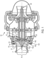
FIG. 1 is a side view of a rotor assembly in accordance with embodiments; and -
FIG. 2 is a side view of a rotor assembly in accordance with embodiments. - In many applications, such as air cycle machines (ACMs) of supersonic aircrafts, maximizing speed may be required to achieve required performance level of a turbo-expander. This has recently led to development of relatively small rotors for maximum mass flow rate. For high rotor speed (NS) rotors, increasing flow rate tends to be challenging however due unfavorable exducer angles and/or exducer chocking. To minimize these issues, it has been found that exducer area for flow should be maximized.
- Maximizing exducer area for flow presents further challenges. For example, the exducer area cannot typically be larger than a shroud outer diameter, less a minimum hub diameter that has been generally held constant. This is because, in typical machine, support at an impeller eye dictates the minimum hub diameter. Therefore, the only choice for maximizing exducer area has been to maximize the shroud outer diameter, which requires a substantial modification of rotor design. These challenges can be exacerbated by the need for rotor balance and the additional need to service all dynamic loads (i.e., on a plane).
- Thus, as will be described below, a minimized or zeroed rotor hub internal diameter (ID) is provided for use in turbomachinery. The minimized or zeroed rotor hub ID is achieved through the use of a one-piece or two-piece rotor impeller to which a rotor shaft is directly coupled. The one-piece or two-piece rotor impeller has a blade section that converges to a point at a rotational axis of the rotor shaft with a minimized or zeroed ID at that point without sacrificing balance and the ability to service dynamic loads.
- With reference to
FIG. 1 , arotor assembly 101 is provided and includes arotor impeller 110 and arotor shaft 120. Therotor impeller 110 can be a one-piece rotor impeller and includes a blade section 111 and aforward section 112 from which the blade section 111 extends in the aft direction. Therotor shaft 120 is rotatable about a rotational axis A thereof and includes anaft section 121 at which therotor shaft 120 terminates. Theaft section 121 is directly attached to theforward section 112 of therotor impeller 110 by, e.g., a threadedconnection 130. The blade section 111 of therotor impeller 110 includes anexit blade 113 and aconverging blade 114 that is configured to converge to a point P with a minimized or zeroed ID. The point P can be defined along the rotational axis A. For purposes of clarity and brevity, the following description will relate to the case of the convergingblade 114 converging to the point P with the zeroed ID. - In accordance with embodiments, as shown in
FIG. 1 , since the convergingblade 114 converges to the point with the zeroed ID, a flow area FA of therotor assembly 101 can be increased without changing a diameter of theouter shroud 102. - As shown in
FIG. 1 , the convergingblade 114 extends in the aft direction aft from theforward section 112 and converges toward the point P with anon-linear profile 1140. Thenon-linear profile 1140 can include asteep forward portion 1141, ashallow aft portion 1142 and acurved portion 1143 that is axially interposed between thesteep forward portion 1141 and theshallow aft portion 1142. - In accordance with embodiments, the converging
blade 114 extends aft from anaft edge 1130 of theexit blade 113 by a length L which is not more than 1/10 of a diameter D of theexit blade 113. - With reference to
FIG. 2 , arotor assembly 201 is provided and includes a two-piece rotor impeller 210 and arotor shaft 220. The two-piece rotor impeller 210 includes ablade section 211 and aforward section 212, which is connected to theblade section 211 and from which theblade section 211 extends in the aft direction. Theforward section 212 and theblade section 211 can be connected by at least one or more of a threaded connection, a bolted connection, a brazed connection, a welded connection and anadhesive connection 225. Therotor shaft 220 is rotatable about a rotational axis A thereof and includes anaft section 221 at which therotor shaft 220 terminates. Theaft section 221 is directly attached to theforward section 212 of therotor impeller 210 by, e.g., a threadedconnection 230. Theblade section 211 of therotor impeller 210 includes anexit blade 213 and a convergingblade 214 that is configured to converge to a point P with a minimized or zeroed ID. The point P can be defined along the rotational axis A. For purposes of clarity and brevity, the following description will relate to the case of the convergingblade 214 converging to the point P with the zeroed ID. - In accordance with embodiments, the
blade section 211 and theforward section 212 can be formed of different materials. For example, theblade section 211 can include polymeric material and theforward section 212 can include metallic material. - In accordance with embodiments, as shown in
FIG. 1 , since the convergingblade 214 converges to the point with the zeroed ID, a flow area FA of therotor assembly 201 can be increased without changing a diameter of theouter shroud 202. - As shown in
FIG. 2 , the convergingblade 214 extends in the aft direction aft from theforward section 212 and converges toward the point P with anon-linear profile 2140. Thenon-linear profile 2140 can include asteep forward portion 2141, ashallow aft portion 2142 and acurved portion 2143 that is axially interposed between thesteep forward portion 2141 and theshallow aft portion 2142. - In accordance with embodiments, the converging
blade 214 extends aft from anaft edge 2130 of theexit blade 213 by a length L which is not more than 1/10 of a diameter D of theexit blade 213. - Technical effects and benefits of the present disclosure are the provision of a rotor assembly with improved rotor extruder angles and corresponding aerodynamic performance. This leads to improved stage efficiency, increasing choking area (i.e., by about 15% which in turn leads to reduced choking incidence) and an increased operating margin.
- The corresponding structures, materials, acts and equivalents of all means or step plus function elements in the claims below are intended to include any structure, material, or act for performing the function in combination with other claimed elements as specifically claimed. The description of the present disclosure has been presented for purposes of illustration and description, but is not intended to be exhaustive or limited to the technical concepts in the form disclosed. Many modifications and variations will be apparent to those of ordinary skill in the art without departing from the scope and spirit of the disclosure. The embodiments were chosen and described in order to best explain the principles of the disclosure and the practical application and to enable others of ordinary skill in the art to understand the disclosure for various embodiments with various modifications as are suited to the particular use contemplated.
- While the preferred embodiments to the disclosure have been described, it will be understood that those skilled in the art, both now and in the future, may make various improvements and enhancements which fall within the scope of the claims which follow. These claims should be construed to maintain the proper protection for the disclosure first described.
Claims (15)
- A rotor assembly, comprising:a rotor impeller comprising a blade section and a forward section; anda rotor shaft comprising an aft section at which the rotor shaft terminates, the aft section being directly attached to the forward section of the rotor impeller,the blade section comprising a converging blade configured to converge to a point with a minimized internal diameter (ID).
- The rotor assembly according to claim 1, wherein the rotor impeller is a one-piece rotor impeller.
- The rotor assembly according to claim 1 or 2, wherein the blade section extends aft from the forward section.
- The rotor assembly according to any preceding claim, wherein the point at which the converging blade of the blade section converges is defined along a rotational axis of the rotor shaft.
- The rotor assembly according to any preceding claim, wherein the blade section of the rotor impeller comprises the converging blade and an exit blade.
- The rotor assembly according to claim 5, wherein the converging blade extends aft from the forward section and converges toward the point with a non-linear profile.
- The rotor assembly according to claim 6, wherein the non-linear profile comprises:a steep forward portion;a shallow aft portion; anda curved portion axially interposed between the steep forward portion and the shallow aft portion.
- The rotor assembly according to any of claims 5 to 7, wherein the converging blade extends aft from an aft edge of the exit blade by a length which is not more than 1/10 of a diameter of the exit blade.
- The rotor assembly according to any preceding claim, wherein the aft section of the rotor shaft is connected to the forward section of the rotor impeller by a threaded connection.
- A rotor assembly, comprising:a rotor impeller comprising a blade section and a forward section; anda rotor shaft comprising an aft section at which the rotor shaft terminates, the aft section being directly attached to the forward section of the rotor impeller,the blade section comprising a converging blade configured to converge to a point with a zeroed internal diameter (ID).
- The rotor assembly according to claim 10, wherein the rotor impeller is a one-piece rotor impeller, and/orwherein the blade section extends aft from the forward section, and/orwherein the point at which the converging blade of the blade section converges is defined along a rotational axis of the rotor shaft, and/orwherein the aft section of the rotor shaft is connected to the forward section of the rotor impeller by a threaded connection.
- The rotor assembly according to claim 10 or 11, wherein the blade section of the rotor impeller comprises the converging blade and an exit blade.
- The rotor assembly according to claim 12, wherein the converging blade extends aft from the forward section and converges toward the point with a non-linear profile;
wherein optionally, the non-linear profile comprises:a steep forward portion;a shallow aft portion; anda curved portion axially interposed between the steep forward portion and the shallow aft portion, and/orwherein the converging blade extends aft from an aft edge of the exit blade by a length which is not more than 1/10 of a diameter of the exit blade. - A rotor assembly, comprising:a one-piece rotor impeller comprising an exit blade, a converging blade and a forward section; anda rotor shaft that is rotatable about a rotational axis thereof and comprises an aft section at which the rotor shaft terminates, the aft section being directly attached to the forward section of the rotor impeller,the converging blade of the blade section being configured to converge with a non-linear profile to a point defined along the rotational axis and aft of an aft edge of the exit blade with a zeroed internal diameter (ID).
- The rotor assembly according to claim 14, wherein the converging blade of the blade section extends aft from the aft edge of the exit blade by a length which is not more than 1/10 of a diameter of the exit blade.
Applications Claiming Priority (1)
| Application Number | Priority Date | Filing Date | Title |
|---|---|---|---|
| US18/366,243 US20250052254A1 (en) | 2023-08-07 | 2023-08-07 | Radial impeller with maximized inducer area |
Publications (1)
| Publication Number | Publication Date |
|---|---|
| EP4512996A1 true EP4512996A1 (en) | 2025-02-26 |
Family
ID=92259020
Family Applications (1)
| Application Number | Title | Priority Date | Filing Date |
|---|---|---|---|
| EP24193097.3A Pending EP4512996A1 (en) | 2023-08-07 | 2024-08-06 | Radial impeller with maximized inducer area |
Country Status (2)
| Country | Link |
|---|---|
| US (1) | US20250052254A1 (en) |
| EP (1) | EP4512996A1 (en) |
Citations (5)
| Publication number | Priority date | Publication date | Assignee | Title |
|---|---|---|---|---|
| US20040020203A1 (en) * | 2002-07-30 | 2004-02-05 | Arnold Steven Don | High-pressure ratio turbocharger |
| US20140369840A1 (en) * | 2011-12-23 | 2014-12-18 | Napier Turbochargers Limited | Connector |
| EP2933499B1 (en) * | 2012-11-28 | 2018-11-21 | Napier Turbochargers Limited | Turbocharger impeller screwed onto shaft with arrangement for accommodating thermal dilatation |
| US20200063652A1 (en) * | 2018-08-21 | 2020-02-27 | Ryan Harold SALENBIEN | Hub-Less And Nut-Less Turbine Wheel And Compressor Wheel Design For Turbochargers |
| US20210207563A1 (en) * | 2018-08-21 | 2021-07-08 | Ryan Harold SALENBIEN | Hub-less and nut-less turbine wheel and compressor wheel designs and installation/removal tool |
Family Cites Families (7)
| Publication number | Priority date | Publication date | Assignee | Title |
|---|---|---|---|---|
| US494890A (en) * | 1893-04-04 | eateatj | ||
| US3216649A (en) * | 1965-01-14 | 1965-11-09 | Joseph V Foa | Generators of rotating flow patterns |
| US4688663A (en) * | 1982-05-10 | 1987-08-25 | Marchand William C | Motor and brake control for a multi-stage turbine engine |
| DE102008045171B4 (en) * | 2008-08-30 | 2019-07-18 | Daimler Ag | Radial vane wheel and method for producing a radial vane wheel for a rotor of an exhaust gas turbocharger |
| DE102012215248B4 (en) * | 2012-08-28 | 2014-12-24 | Schaeffler Technologies Gmbh & Co. Kg | Turbine rotor of an exhaust gas turbocharger |
| US10272542B2 (en) * | 2015-05-08 | 2019-04-30 | Balance Technology, Inc. | Abrasive water jet balancing apparatus and method for rotating components |
| EP3712438B1 (en) * | 2017-11-15 | 2023-09-06 | Mitsubishi Heavy Industries Engine & Turbocharger, Ltd. | Compressor impeller, compressor, and turbocharger |
-
2023
- 2023-08-07 US US18/366,243 patent/US20250052254A1/en active Pending
-
2024
- 2024-08-06 EP EP24193097.3A patent/EP4512996A1/en active Pending
Patent Citations (5)
| Publication number | Priority date | Publication date | Assignee | Title |
|---|---|---|---|---|
| US20040020203A1 (en) * | 2002-07-30 | 2004-02-05 | Arnold Steven Don | High-pressure ratio turbocharger |
| US20140369840A1 (en) * | 2011-12-23 | 2014-12-18 | Napier Turbochargers Limited | Connector |
| EP2933499B1 (en) * | 2012-11-28 | 2018-11-21 | Napier Turbochargers Limited | Turbocharger impeller screwed onto shaft with arrangement for accommodating thermal dilatation |
| US20200063652A1 (en) * | 2018-08-21 | 2020-02-27 | Ryan Harold SALENBIEN | Hub-Less And Nut-Less Turbine Wheel And Compressor Wheel Design For Turbochargers |
| US20210207563A1 (en) * | 2018-08-21 | 2021-07-08 | Ryan Harold SALENBIEN | Hub-less and nut-less turbine wheel and compressor wheel designs and installation/removal tool |
Also Published As
| Publication number | Publication date |
|---|---|
| US20250052254A1 (en) | 2025-02-13 |
Similar Documents
| Publication | Publication Date | Title |
|---|---|---|
| US11199196B2 (en) | Geared turbofan engine | |
| CN108425883B (en) | Gas turbine engine fan blade | |
| US8157514B2 (en) | Components for gas turbine engines | |
| JP3958383B2 (en) | Chip shroud assembly for axial gas turbine engines | |
| US8231341B2 (en) | Hybrid compressor | |
| US20200011274A1 (en) | High efficiency gas turbine engine | |
| US8534997B2 (en) | Fluid flow machine with a blade row group featuring a meridional edge distance | |
| EP2518326A2 (en) | Centrifugal compressor assembly with stator vane row | |
| US8210794B2 (en) | Axial-centrifugal compressor with ported shroud | |
| US20210301764A1 (en) | Gas turbine engine | |
| CN108425884A (en) | Gas-turbine unit fan blade | |
| US20210372288A1 (en) | Compressor stator with leading edge fillet | |
| US12037921B2 (en) | Fan for a turbine engine | |
| CN110382841B (en) | Protected core portal | |
| US9856740B2 (en) | Tip-controlled integrally bladed rotor for gas turbine engine | |
| CA2567940C (en) | Methods and apparatuses for gas turbine engines | |
| EP4517047A1 (en) | Radial impeller with maximized inducer area | |
| US20250052254A1 (en) | Radial impeller with maximized inducer area | |
| US11220910B2 (en) | Compressor stator | |
| WO2019102231A1 (en) | A flow assembly for an axial turbomachine | |
| US20200063569A1 (en) | Fan blade | |
| JP7558128B2 (en) | Two-shaft gas turbine | |
| CA2658412C (en) | Hybrid compressor | |
| EP4512999A1 (en) | Turbine rotor dovetail structure with splines | |
| EP4290053A1 (en) | Passive cooling system for blade tip clearance optimization |
Legal Events
| Date | Code | Title | Description |
|---|---|---|---|
| PUAI | Public reference made under article 153(3) epc to a published international application that has entered the european phase |
Free format text: ORIGINAL CODE: 0009012 |
|
| STAA | Information on the status of an ep patent application or granted ep patent |
Free format text: STATUS: THE APPLICATION HAS BEEN PUBLISHED |
|
| AK | Designated contracting states |
Kind code of ref document: A1 Designated state(s): AL AT BE BG CH CY CZ DE DK EE ES FI FR GB GR HR HU IE IS IT LI LT LU LV MC ME MK MT NL NO PL PT RO RS SE SI SK SM TR |
|
| STAA | Information on the status of an ep patent application or granted ep patent |
Free format text: STATUS: REQUEST FOR EXAMINATION WAS MADE |
|
| 17P | Request for examination filed |
Effective date: 20250822 |