EP4512995A2 - Counter-weight for use with a rotor module, rotor module and method for zeroing out a center of gravity of a plurality of blades with respect to an axis of a rotor disk the plurality of blades are secured to - Google Patents
Counter-weight for use with a rotor module, rotor module and method for zeroing out a center of gravity of a plurality of blades with respect to an axis of a rotor disk the plurality of blades are secured to Download PDFInfo
- Publication number
- EP4512995A2 EP4512995A2 EP24196186.1A EP24196186A EP4512995A2 EP 4512995 A2 EP4512995 A2 EP 4512995A2 EP 24196186 A EP24196186 A EP 24196186A EP 4512995 A2 EP4512995 A2 EP 4512995A2
- Authority
- EP
- European Patent Office
- Prior art keywords
- axis
- counter
- rotor
- blades
- pair
- Prior art date
- Legal status (The legal status is an assumption and is not a legal conclusion. Google has not performed a legal analysis and makes no representation as to the accuracy of the status listed.)
- Pending
Links
Images


Classifications
-
- F—MECHANICAL ENGINEERING; LIGHTING; HEATING; WEAPONS; BLASTING
- F01—MACHINES OR ENGINES IN GENERAL; ENGINE PLANTS IN GENERAL; STEAM ENGINES
- F01D—NON-POSITIVE DISPLACEMENT MACHINES OR ENGINES, e.g. STEAM TURBINES
- F01D5/00—Blades; Blade-carrying members; Heating, heat-insulating, cooling or antivibration means on the blades or the members
- F01D5/02—Blade-carrying members, e.g. rotors
- F01D5/027—Arrangements for balancing
-
- G—PHYSICS
- G01—MEASURING; TESTING
- G01M—TESTING STATIC OR DYNAMIC BALANCE OF MACHINES OR STRUCTURES; TESTING OF STRUCTURES OR APPARATUS, NOT OTHERWISE PROVIDED FOR
- G01M1/00—Testing static or dynamic balance of machines or structures
- G01M1/12—Static balancing; Determining position of centre of gravity
- G01M1/122—Determining position of centre of gravity
-
- F—MECHANICAL ENGINEERING; LIGHTING; HEATING; WEAPONS; BLASTING
- F01—MACHINES OR ENGINES IN GENERAL; ENGINE PLANTS IN GENERAL; STEAM ENGINES
- F01D—NON-POSITIVE DISPLACEMENT MACHINES OR ENGINES, e.g. STEAM TURBINES
- F01D5/00—Blades; Blade-carrying members; Heating, heat-insulating, cooling or antivibration means on the blades or the members
- F01D5/12—Blades
- F01D5/14—Form or construction
- F01D5/16—Form or construction for counteracting blade vibration
-
- F—MECHANICAL ENGINEERING; LIGHTING; HEATING; WEAPONS; BLASTING
- F01—MACHINES OR ENGINES IN GENERAL; ENGINE PLANTS IN GENERAL; STEAM ENGINES
- F01D—NON-POSITIVE DISPLACEMENT MACHINES OR ENGINES, e.g. STEAM TURBINES
- F01D5/00—Blades; Blade-carrying members; Heating, heat-insulating, cooling or antivibration means on the blades or the members
- F01D5/30—Fixing blades to rotors; Blade roots ; Blade spacers
- F01D5/3007—Fixing blades to rotors; Blade roots ; Blade spacers of axial insertion type
-
- G—PHYSICS
- G01—MEASURING; TESTING
- G01M—TESTING STATIC OR DYNAMIC BALANCE OF MACHINES OR STRUCTURES; TESTING OF STRUCTURES OR APPARATUS, NOT OTHERWISE PROVIDED FOR
- G01M1/00—Testing static or dynamic balance of machines or structures
- G01M1/30—Compensating imbalance
- G01M1/36—Compensating imbalance by adjusting position of masses built-in the body to be tested
-
- G—PHYSICS
- G01—MEASURING; TESTING
- G01M—TESTING STATIC OR DYNAMIC BALANCE OF MACHINES OR STRUCTURES; TESTING OF STRUCTURES OR APPARATUS, NOT OTHERWISE PROVIDED FOR
- G01M15/00—Testing of engines
- G01M15/14—Testing gas-turbine engines or jet-propulsion engines
-
- F—MECHANICAL ENGINEERING; LIGHTING; HEATING; WEAPONS; BLASTING
- F01—MACHINES OR ENGINES IN GENERAL; ENGINE PLANTS IN GENERAL; STEAM ENGINES
- F01D—NON-POSITIVE DISPLACEMENT MACHINES OR ENGINES, e.g. STEAM TURBINES
- F01D21/00—Shutting-down of machines or engines, e.g. in emergency; Regulating, controlling, or safety means not otherwise provided for
- F01D21/003—Arrangements for testing or measuring
-
- F—MECHANICAL ENGINEERING; LIGHTING; HEATING; WEAPONS; BLASTING
- F05—INDEXING SCHEMES RELATING TO ENGINES OR PUMPS IN VARIOUS SUBCLASSES OF CLASSES F01-F04
- F05D—INDEXING SCHEME FOR ASPECTS RELATING TO NON-POSITIVE-DISPLACEMENT MACHINES OR ENGINES, GAS-TURBINES OR JET-PROPULSION PLANTS
- F05D2220/00—Application
- F05D2220/30—Application in turbines
- F05D2220/36—Application in turbines specially adapted for the fan of turbofan engines
-
- F—MECHANICAL ENGINEERING; LIGHTING; HEATING; WEAPONS; BLASTING
- F05—INDEXING SCHEMES RELATING TO ENGINES OR PUMPS IN VARIOUS SUBCLASSES OF CLASSES F01-F04
- F05D—INDEXING SCHEME FOR ASPECTS RELATING TO NON-POSITIVE-DISPLACEMENT MACHINES OR ENGINES, GAS-TURBINES OR JET-PROPULSION PLANTS
- F05D2230/00—Manufacture
- F05D2230/60—Assembly methods
-
- F—MECHANICAL ENGINEERING; LIGHTING; HEATING; WEAPONS; BLASTING
- F05—INDEXING SCHEMES RELATING TO ENGINES OR PUMPS IN VARIOUS SUBCLASSES OF CLASSES F01-F04
- F05D—INDEXING SCHEME FOR ASPECTS RELATING TO NON-POSITIVE-DISPLACEMENT MACHINES OR ENGINES, GAS-TURBINES OR JET-PROPULSION PLANTS
- F05D2260/00—Function
- F05D2260/12—Testing on a test bench
-
- F—MECHANICAL ENGINEERING; LIGHTING; HEATING; WEAPONS; BLASTING
- F05—INDEXING SCHEMES RELATING TO ENGINES OR PUMPS IN VARIOUS SUBCLASSES OF CLASSES F01-F04
- F05D—INDEXING SCHEME FOR ASPECTS RELATING TO NON-POSITIVE-DISPLACEMENT MACHINES OR ENGINES, GAS-TURBINES OR JET-PROPULSION PLANTS
- F05D2260/00—Function
- F05D2260/83—Testing, e.g. methods, components or tools therefor
-
- F—MECHANICAL ENGINEERING; LIGHTING; HEATING; WEAPONS; BLASTING
- F05—INDEXING SCHEMES RELATING TO ENGINES OR PUMPS IN VARIOUS SUBCLASSES OF CLASSES F01-F04
- F05D—INDEXING SCHEME FOR ASPECTS RELATING TO NON-POSITIVE-DISPLACEMENT MACHINES OR ENGINES, GAS-TURBINES OR JET-PROPULSION PLANTS
- F05D2260/00—Function
- F05D2260/96—Preventing, counteracting or reducing vibration or noise
Definitions
- This disclosure relates to gas turbine engines, and more particularly to an apparatus and method for a partially bladed rotor test to render a bladed rotor so that its design can simultaneously reach the goals of a zero offset of mass centroid and symmetrical mass moments of inertia.
- Gas turbine engines typically include a fan section, a compressor section, a combustor section and a turbine section. During operation, air is pressurized in the compressor section and is mixed with fuel and burned in the combustor section to generate hot combustion gases. The hot combustion gases are communicated through the turbine section, which extracts energy from the hot combustion gases to power the compressor section and other gas turbine engine loads.
- Both the compressor and turbine sections may include alternating series of rotating blades and stationary vanes that extend into the core flow path of the gas turbine engine.
- turbine blades rotate and extract energy from the hot combustion gases that are communicated along the core flow path of the gas turbine engine.
- the turbine vanes which generally do not rotate, guide the airflow and prepare it for the next set of blades.
- the fan section also includes rotating fan blades.
- the fan blades, turbine blades and compressor blades all rotate at high speeds.
- the availability of the blades is often limited or otherwise expensive. Therefore, when testing the new blades it is desirable to have a partially bladed rotor due to the scarcity of the blades.
- this will result in a rotor with both an offset of mass centroid from its rotational center and an asymmetry of mass moments of inertia along its two principal moment of inertia axes, inducing a potential instability during rotation of the partially bladed rotor during tests.
- a counter weight for use with a rotor module including: a root portion; a main body portion that extends away from the root portion; a pair of side portions each extending laterally away from opposite sides of the main body portion; and at least one plate secure to one of the opposite sides of the main body portion in order to adjust a weight of the counter weight.
- the at least one plate is a pair of plates secured to the opposite sides of the main body portion via bolts that pass through openings in the pair of plates and the main body portion.
- an edge of the pair of plates contacts a surface of the pair of side portions when they are secured to the main body portion.
- the root portion, the main body portion and the pair of side portions are all formed as a single unitary item or monolithic structure.
- an edge of the at least one plate contacts a surface of one of the pair of side portions when it is secured to the main body portion.
- the pair of side portions extend from an end portion of the main body portion.
- a rotor module including: a blade cluster of a plurality of blades secured to a rotor disk of the rotor module; and counter weights secured to the rotor disk, wherein a center of gravity of the plurality of blades is zeroed out with respect to an axis "O" of the rotor disk and the rotor module further comprises an "X" axis and a "Y" axis each orthogonally arranged with respect to the axis "O” of the rotor disk and wherein the blade cluster and the counter weights are configured to provide a configuration with respect to the axis "O" of the rotor disk and a moment of inertia Jx about the X axis is equal to a moment of inertia Jy about the Y axis when the rotor module is rotated about the axis "O" of the rotor disk, wherein each counter weight of the counter weights includes: a root portion;
- the counter weights is a pair of counter weights and the pair of counter weights include a first counter weight group and a second counter weight group.
- the first counter weight group comprises a pair of counter weights and the second counter weight group comprises a pair of counter weights.
- the pair of counter weights of the first counter weight group are of different weights (e.g. relative to each other) and the pair of counter weights and the second counter weight group are of different weights (e.g. relative to each other).
- a center of gravity of the blade cluster is designated at a twelve clock position with respect to the axis "O" and one of the counter weights is at a four clock position with respect to the axis "O" and the another one of the counter weights is at an eight clock position with respect to the axis "O".
- the counter weights include a first counter weight group and a second counter weight group and the first counter weight group comprises a pair of counter weights and the second counter weight group comprises a pair of counter weights.
- the plurality of blades are fan blades.
- the plurality of blades are three fan blades.
- the at least one plate is a pair of plates secured to opposite sides of the main body portion via bolts that pass through openings in the pair of plates and the main body portion.
- an edge of the at least one plate contacts a surface of one of the side portions when they are secured to the main body portion.
- the root portion, the main body portion and the pair of side portions are all formed as a single unitary item or monolithic structure.
- the pair of side portions includes a sacrificial side portion.
- the sacrificial side portion may extend radially e.g. relative to the rest of a respective side portion.
- a method for zeroing out a center of gravity of a plurality of blades with respect to an axis "O" of a rotor disk the plurality of blades are secured to including: securing a blade cluster of the plurality of blades to the rotor disk; and securing counter weights to the rotor disk, wherein the center of gravity of the plurality of blades is zeroed out with respect to the axis "O" of the rotor disk and the rotor disk further comprises an "X" axis and a "Y” axis each orthogonally arranged with respect to the axis "O” of the rotor disk and wherein the blade cluster and the counter weights are configured to provide a configuration with respect to the axis "O" of the rotor disk and a moment of inertia Jx about the X axis is equal to a moment of inertia Jy about the Y axis when the rotor module is
- the X axis and Y axis are orthogonal to each other and to the axis O.
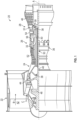
- FIG. 1 schematically illustrates a gas turbine engine 20.
- the gas turbine engine 20 is disclosed herein as a two-spool turbofan that generally incorporates a fan section 22, a compressor section 24, a combustor section 26 and a turbine section 28.
- Alternative engines might include other systems or features.
- the fan section 22 drives air along a bypass flow path B in a bypass duct, while the compressor section 24 drives air along a core flow path C for compression and communication into the combustor section 26 then expansion through the turbine section 28.
- FIG. 1 schematically illustrates a gas turbine engine 20.
- the gas turbine engine 20 is disclosed herein as a two-spool turbofan that generally incorporates a fan section 22, a compressor section 24, a combustor section 26 and a turbine section 28.
- Alternative engines might include other systems or features.
- the fan section 22 drives air along a bypass flow path B in a bypass duct
- the compressor section 24 drives air along a core flow path C for compression and communication into the combustor section 26
- the exemplary engine 20 generally includes a low speed spool 30 and a high speed spool 32 mounted for rotation about an engine central longitudinal axis A relative to an engine static structure 36 via several bearing systems 38. It should be understood that various bearing systems 38 at various locations may alternatively or additionally be provided, and the location of bearing systems 38 may be varied as appropriate to the application.
- the low speed spool 30 generally includes an inner shaft 40 that interconnects a fan 42, a first or low pressure compressor 44 and a first or low pressure turbine 46.
- the inner shaft 40 is connected to the fan 42 through a speed change mechanism, which in exemplary gas turbine engine 20 is illustrated as a geared architecture 48 to drive the fan 42 at a lower speed than the low speed spool 30.
- the high speed spool 32 includes an outer shaft 50 that interconnects a second or high pressure compressor 52 and a second or high pressure turbine 54.
- a combustor 56 is arranged in exemplary gas turbine 20 between the high pressure compressor 52 and the high pressure turbine 54.
- a mid-turbine frame 57 of the engine static structure 36 is arranged generally between the high pressure turbine 54 and the low pressure turbine 46.
- the mid-turbine frame 57 further supports bearing systems 38 in the turbine section 28.
- the inner shaft 40 and the outer shaft 50 are concentric and rotate via bearing systems 38 about the engine central longitudinal axis A which is collinear with their longitudinal axe
- the core airflow is compressed by the low pressure compressor 44 then the high pressure compressor 52, mixed and burned with fuel in the combustor 56, then expanded over the high pressure turbine 54 and low pressure turbine 46.
- the mid-turbine frame 57 includes airfoils 59 which are in the core airflow path C.
- the turbines 46, 54 rotationally drive the respective low speed spool 30 and high speed spool 32 in response to the expansion.
- gear system 48 may be located aft of combustor section 26 or even aft of turbine section 28, and fan section 22 may be positioned forward or aft of the location of gear system 48.
- FIG. 2 illustrates an end view of an unsymmetrical rotor module 70 with a limited amount of blades, which in the illustrated embodiment may be fan blades 72 of the fan 42.
- the rotor module 70 includes a rotor or rotor disk 74 to which a plurality of fan blades 72 are secured thereto for testing.
- the rotor module 70 is configured to be rotated about an axis "O", which may be analogous to axis "A" illustrated in FIG. 1 .
- a cluster of blades 73 are secured to the rotor or rotor disk 74. As illustrated, the cluster of blades 73 comprises three fan blades 72.
- various embodiments of the present disclosure are not specifically limited to three fan blades 72 as more or less than three blades may be used.
- new fan blades 72 are designed and developed the availability of these blades 72 is often limited or otherwise expensive to reproduce.
- testing occurs with a limited amount of blades 72 secured to the rotor or rotor disk 74.
- the rotor module 70 has a zeroed imbalance by securing pairs of counter weights to the rotor module 70. This may be referred to as a tri-lobe configuration as the fan blades 72 are off-set by the pairs of counter weights.
- the pairs of counter weights may be referred to as a first counter weight group 78 and a second counter weight group 80. In this configuration, there is no dynamic un-symmetry as the moment of inertia Jx about the X axis is equal to the moment of inertia Jy about the Y axis when this rotor module 70 is rotated about axis "O" with the counter weight configuration illustrated in FIG. 2 .
- a center of gravity of the blade cluster 73 is designated at the twelve clock position when referring to view illustrated in FIG. 2
- the two counter weight clusters, the first counter weight group 78 and the second counter weight group 80 are respectively at the four and eight clock positions when referring to view illustrated in FIG. 2 , thus forming a tri-lobe configuration.
- the center of gravity of the blade cluster 73, the first counter weight group 78 and the second counter weight group 80 are offset by 120 degrees with respect to each with reference to axis "O".
- other configurations are considered to be within the scope of the present disclosure.
- the counter weights of the first counter weight group 78 and the second counter weight group 80 can be sized to enable a zero nominal imbalance as well as an axi-symmetrical moment of inertia for the partially bladed rotor 74.
- the pair of counter weights 82 of the first counter weight group 78 are of different weights and/or sizes and/or lengths and the pair of counter weights 84 of the second counter weight group 80 are of different weights and/or sizes and/or lengths.
- the X and Y axes may be orientated at any location with respect to the "O" axis as they rotated about the "O" axis.
- FIG. 2 illustrates a rotor module 70 with a limited amount of fan blades 72 and counter weights 76 in accordance with the present disclosure
- various exemplary embodiments of the present disclosure may be applied to the testing of compressor blades and turbine blades.
- the present disclosure is not limited to use with fan blades 72 only.
- the apparatus and method of the present disclosure allows a limited amount of blades to be used for rotor tests such as "Bird Strike” or "Containment” tests for fan blades.
- the apparatus and method enables a zero nominal imbalance for the entire rotor 74 and enables the elimination of the potential instability due to inertia asymmetry.
- the counter weights 82, 84 have a root portion 90 configured to slide into a complementary slot of the rotor or rotor disk 74 as is known in the related arts. Extending away from the root portion is a main body portion 92 that extends in a radial direction away from the root portion 90. In one embodiment, a pair of side portions 93 extend laterally away from opposite sides of the main body portion 92.
- the pair of side portions 93 and the main body portion 92 terminate in an end portion 96 that extends laterally away from opposite sides of the main body portion 92 such that the counter weight 82, 84 is configured to have a "T" shaped tip portion 98.
- the counter weights 82, 84 are formed as a single unitary item wherein the root portion 90, the main body portion 92 and the end portion 96 are all formed as a single unitary item or monolithic structure.
- the "T" shaped tip portion 98 allows for plates 100 to be secured to opposite sides of the main body portion 92 in order to adjust the weight of the counter weight 82, 84 as needed in order to provide the zero nominal imbalance as well as the axi-symmetrical moment of inertia for the partially bladed rotor 74 as discussed above.
- the plates 100 are secured to the opposite sides of the main body portion 92 via bolts 102 that pass through openings in the plates 100 and the main body portion 92.
- the bolts 102 are in one non-limiting embodiment, secured to the main body portion 92 via complementary nuts 104 that engage threads of the bolts 102.
- fasteners may be used to secure the plates 100 to the main body portion 92 and various embodiments of the present disclosure are not specifically limited to the use of bolts 102 for securement of the plates 100 to the main body portion 92.
- suitable fasteners include but are not limited to rivets, welds or any other types of fasteners.
- the "T" shaped tip portion 98 By providing the "T" shaped tip portion 98 an edge 106 of the plates 100 is configured to contact a surface 108 of the end portion 96. This helps to limit movement of the plates in the direction of arrow 110 due to centrifugal forces in the direction of arrow 110 as the rotor module 70 is rotated about axis "O". As such and in one embodiment, the "T" shaped tip portion 98 is intended to carry all the centrifugal load of the plates 100, in order to avoid loading the bolts 102 in shear and the bolts 102 are only included to provide clamp force. Alternatively and in another embodiment, the plates 100 when clamped to the "T" shaped tip portion 98 may be slightly spaced from the surface 108 of the end portion 96.
- a length "L" of the counter weight 82, 84 may also vary in order to manipulate or vary the weight and pull of first counter weight group 78 and/or the second counter weight group 80.
- the weight of the counter weight 82, 84 can now be adjusted to offset different blades without making new counter weight bodies.
- bolts 102 are used to clamp the plates 100 to the main body portion 92 and the "T "shaped portion 98 supports the centrifugal load of the plates 100.
- the counter weight 82, 84 is configured such that the pair of side portions 93 do not extend from the end portion 96 but from a portion of the main body portion 92 such that the main body portion 92 has a lower portion 95 located below the pair of side portions 93 and an upper portion 97 located above the pair of side portions 93.
- the counter weights 82, 84 are formed as a single unitary item wherein the root portion 90, the main body portion 92 and the side portions 93 are all formed as a single unitary item or monolithic structure.
- This configuration also allows for plates 100 to be secured to opposite sides of the main body portion 92 in order to adjust the weight of the counter weight 82, 84 as needed in order to provide the zero nominal imbalance as well as the axi-symmetrical moment of inertia for the partially bladed rotor 74 as discussed above.
- the plates 100 are secured to the opposite sides of the main body portion 92 via bolts 102 that pass through openings in the plates 100 and the main body portion 92.
- the bolts 102 are in one non-limiting embodiment, secured to the main body portion 92 via complementary nuts 104 that engage threads of the bolts 102.
- fasteners may be used to secure the plates 100 to the main body portion 92 and various embodiments of the present disclosure are not specifically limited to the use of bolts 102 for securement of the plates 100 to the main body portion 92.
- suitable fasteners include but are not limited to rivets, welds or any other types of fasteners.
- the side portions 93 are intended to carry all the centrifugal load of the plates 100, in order to avoid loading the bolts 102 in shear and the bolts 102 are only included to provide clamp force.
- the plates 100 when clamped to main body portion may be slightly spaced from the surface 108 of the side portions 93.
- a length "L" of the counter weight 82, 84 may also vary in order to manipulate or vary the weight and pull of first counter weight group 78 and/or the second counter weight group 80.
- the weight of the counter weight 82, 84 can now be adjusted to offset different blades without making new counter weight bodies.
- bolts 102 are used to clamp the plates 100 to the main body portion 92 and the side portions 93 support the centrifugal load of the plates 100.
- the pair of side portions 93 include sacrificial side portions 101 that extend either axially up and/or down and/or radially away from the side portions 93.
- These sacrificial side portions 101 add additional weight to the counter weights 82, 84 which can be varied by removing (e.g., by cutting or milling) a portion of the sacrificial side portions 101 from the counter weights 82, 84.
- This embodiment can be used in combination with plate(s) 100 or in lieu of plates 100.
- the counter weights 82, 84 are formed as a single unitary item wherein the root portion 90, the main body portion 92 and the side portions and the sacrificial side portions 101 are all formed as a single unitary item or monolithic structure.
- This configuration also allows for plates 100 to be secured to opposite sides of the main body portion 92 in order to adjust the weight of the counter weight 82, 84 as needed in order to provide the zero nominal imbalance as well as the axi-symmetrical moment of inertia for the partially bladed rotor 74 as discussed above.
- the plates 100 are secured to the opposite sides of the main body portion 92 via bolts 102 that pass through openings in the plates 100 and the main body portion 92.
- the bolts 102 are in one non-limiting embodiment, secured to the main body portion 92 via complementary nuts 104 that engage threads of the bolts 102.
- fasteners may be used to secure the plates 100 to the main body portion 92 and various embodiments of the present disclosure are not specifically limited to the use of bolts 102 for securement of the plates 100 to the main body portion 92.
- suitable fasteners include but are not limited to rivets, welds or any other types of fasteners.
- the side portions 93 are intended to carry all the centrifugal load of the plates 100, in order to avoid loading the bolts 102 in shear and the bolts 102 are only included to provide clamp force.
- the plates 100 when clamped to main body portion may be slightly spaced from the surface 108 of the side portions 93.
- a length "L" of the counter weight 82, 84 may also vary in order to manipulate or vary the weight and pull of first counter weight group 78 and/or the second counter weight group 80.
- the weight of the counter weight 82, 84 can now be adjusted to offset different blades without making new counter weight bodies.
- bolts 102 are used to clamp the plates 100 to the main body portion 92 and the side portions 93 support the centrifugal load of the plates 100.
Landscapes
- Engineering & Computer Science (AREA)
- Physics & Mathematics (AREA)
- General Physics & Mathematics (AREA)
- Mechanical Engineering (AREA)
- General Engineering & Computer Science (AREA)
- Chemical & Material Sciences (AREA)
- Combustion & Propulsion (AREA)
- Aviation & Aerospace Engineering (AREA)
- Structures Of Non-Positive Displacement Pumps (AREA)
- Turbine Rotor Nozzle Sealing (AREA)
- Connection Of Motors, Electrical Generators, Mechanical Devices, And The Like (AREA)
Abstract

Description
- This disclosure relates to gas turbine engines, and more particularly to an apparatus and method for a partially bladed rotor test to render a bladed rotor so that its design can simultaneously reach the goals of a zero offset of mass centroid and symmetrical mass moments of inertia.
- Gas turbine engines typically include a fan section, a compressor section, a combustor section and a turbine section. During operation, air is pressurized in the compressor section and is mixed with fuel and burned in the combustor section to generate hot combustion gases. The hot combustion gases are communicated through the turbine section, which extracts energy from the hot combustion gases to power the compressor section and other gas turbine engine loads.
- Both the compressor and turbine sections may include alternating series of rotating blades and stationary vanes that extend into the core flow path of the gas turbine engine. For example, in the turbine section, turbine blades rotate and extract energy from the hot combustion gases that are communicated along the core flow path of the gas turbine engine. The turbine vanes, which generally do not rotate, guide the airflow and prepare it for the next set of blades. In addition, the fan section also includes rotating fan blades.
- The fan blades, turbine blades and compressor blades, all rotate at high speeds. During the development phase of a new type of blade(s), the availability of the blades is often limited or otherwise expensive. Therefore, when testing the new blades it is desirable to have a partially bladed rotor due to the scarcity of the blades. However, this will result in a rotor with both an offset of mass centroid from its rotational center and an asymmetry of mass moments of inertia along its two principal moment of inertia axes, inducing a potential instability during rotation of the partially bladed rotor during tests.
- In an aspect of the present invention, a counter weight for use with a rotor module is disclosed, including: a root portion; a main body portion that extends away from the root portion; a pair of side portions each extending laterally away from opposite sides of the main body portion; and at least one plate secure to one of the opposite sides of the main body portion in order to adjust a weight of the counter weight.
- In an embodiment of the above, the at least one plate is a pair of plates secured to the opposite sides of the main body portion via bolts that pass through openings in the pair of plates and the main body portion.
- In an embodiment according to any of the previous embodiments, an edge of the pair of plates contacts a surface of the pair of side portions when they are secured to the main body portion.
- In an embodiment according to any of the previous embodiments, the root portion, the main body portion and the pair of side portions are all formed as a single unitary item or monolithic structure.
- In an embodiment according to any of the previous embodiments, an edge of the at least one plate contacts a surface of one of the pair of side portions when it is secured to the main body portion.
- In an embodiment according to any of the previous embodiments, the pair of side portions extend from an end portion of the main body portion.
- In another aspect of the present invention, a rotor module is disclosed, including: a blade cluster of a plurality of blades secured to a rotor disk of the rotor module; and counter weights secured to the rotor disk, wherein a center of gravity of the plurality of blades is zeroed out with respect to an axis "O" of the rotor disk and the rotor module further comprises an "X" axis and a "Y" axis each orthogonally arranged with respect to the axis "O" of the rotor disk and wherein the blade cluster and the counter weights are configured to provide a configuration with respect to the axis "O" of the rotor disk and a moment of inertia Jx about the X axis is equal to a moment of inertia Jy about the Y axis when the rotor module is rotated about the axis "O" of the rotor disk, wherein each counter weight of the counter weights includes: a root portion; a main body portion that extends away from the root portion; a pair of side portions each extending laterally away from opposite sides of the main body portion; and at least one plate secured to one of the opposite sides of the main body portion in order to adjust a weight of the counter weight.
- In an embodiment of the above, the counter weights is a pair of counter weights and the pair of counter weights include a first counter weight group and a second counter weight group.
- In an embodiment according to any of the previous embodiments, the first counter weight group comprises a pair of counter weights and the second counter weight group comprises a pair of counter weights.
- In an embodiment according to any of the previous embodiments, the pair of counter weights of the first counter weight group are of different weights (e.g. relative to each other) and the pair of counter weights and the second counter weight group are of different weights (e.g. relative to each other).
- In an embodiment according to any of the previous embodiments, a center of gravity of the blade cluster is designated at a twelve clock position with respect to the axis "O" and one of the counter weights is at a four clock position with respect to the axis "O" and the another one of the counter weights is at an eight clock position with respect to the axis "O".
- In an embodiment according to any of the previous embodiments, the counter weights include a first counter weight group and a second counter weight group and the first counter weight group comprises a pair of counter weights and the second counter weight group comprises a pair of counter weights.
- In an embodiment according to any of the previous embodiments, the plurality of blades are fan blades.
- In an embodiment according to any of the previous embodiments, the plurality of blades are three fan blades.
- In an embodiment according to any of the previous embodiments, the at least one plate is a pair of plates secured to opposite sides of the main body portion via bolts that pass through openings in the pair of plates and the main body portion.
- In an embodiment according to any of the previous embodiments, an edge of the at least one plate contacts a surface of one of the side portions when they are secured to the main body portion.
- In an embodiment according to any of the previous embodiments, the root portion, the main body portion and the pair of side portions are all formed as a single unitary item or monolithic structure.
- In an embodiment according to any of the previous embodiments, the pair of side portions includes a sacrificial side portion. The sacrificial side portion may extend radially e.g. relative to the rest of a respective side portion.
- In another aspect of the present invention, a method for zeroing out a center of gravity of a plurality of blades with respect to an axis "O" of a rotor disk the plurality of blades are secured to is disclosed, including: securing a blade cluster of the plurality of blades to the rotor disk; and securing counter weights to the rotor disk, wherein the center of gravity of the plurality of blades is zeroed out with respect to the axis "O" of the rotor disk and the rotor disk further comprises an "X" axis and a "Y" axis each orthogonally arranged with respect to the axis "O" of the rotor disk and wherein the blade cluster and the counter weights are configured to provide a configuration with respect to the axis "O" of the rotor disk and a moment of inertia Jx about the X axis is equal to a moment of inertia Jy about the Y axis when the rotor module is rotated about the axis "O" of the rotor disk, wherein each counter weight of the counter weights includes: a root portion; a main body portion that extends away from the root portion; a pair of side portions each extending laterally away from opposite sides of the main body portion; and at least one plate secured to one of the opposite sides of the main body portion in order to adjust a weight of the counter weight.
- In any of the above, the X axis and Y axis are orthogonal to each other and to the axis O.
- The following descriptions should not be considered limiting in any way. With reference to the accompanying drawings, like elements are numbered alike:
-
FIG. 1 is a schematic, partial cross-sectional view of a gas turbine engine in accordance with this disclosure; -
FIG. 2 is an end view of a rotor module with a limited amount of blades and counter weights in accordance with the present disclosure; -
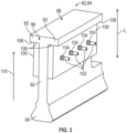
FIG. 3 is a perspective view of a counter weight in accordance with the present disclosure; -
FIG. 4 is a perspective view of a counter weight in accordance another embodiment of the present disclosure; and -
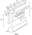
FIG. 5 is a perspective view of a counter weight in accordance another embodiment of the present disclosure. - A detailed description of one or more embodiments of the disclosed apparatus and method are presented herein by way of exemplification and not limitation with reference to the FIGS.
-
FIG. 1 schematically illustrates agas turbine engine 20. Thegas turbine engine 20 is disclosed herein as a two-spool turbofan that generally incorporates afan section 22, acompressor section 24, acombustor section 26 and aturbine section 28. Alternative engines might include other systems or features. Thefan section 22 drives air along a bypass flow path B in a bypass duct, while thecompressor section 24 drives air along a core flow path C for compression and communication into thecombustor section 26 then expansion through theturbine section 28. Although depicted as a two-spool turbofan gas turbine engine in the disclosed non-limiting embodiment, it should be understood that the concepts described herein are not limited to use with two-spool turbofans as the teachings may be applied to other types of turbine engines including three-spool architectures. - The
exemplary engine 20 generally includes alow speed spool 30 and ahigh speed spool 32 mounted for rotation about an engine central longitudinal axis A relative to an enginestatic structure 36 viaseveral bearing systems 38. It should be understood that various bearingsystems 38 at various locations may alternatively or additionally be provided, and the location of bearingsystems 38 may be varied as appropriate to the application. - The
low speed spool 30 generally includes aninner shaft 40 that interconnects afan 42, a first orlow pressure compressor 44 and a first orlow pressure turbine 46. Theinner shaft 40 is connected to thefan 42 through a speed change mechanism, which in exemplarygas turbine engine 20 is illustrated as a gearedarchitecture 48 to drive thefan 42 at a lower speed than thelow speed spool 30. Thehigh speed spool 32 includes anouter shaft 50 that interconnects a second orhigh pressure compressor 52 and a second orhigh pressure turbine 54. Acombustor 56 is arranged inexemplary gas turbine 20 between thehigh pressure compressor 52 and thehigh pressure turbine 54. Amid-turbine frame 57 of the enginestatic structure 36 is arranged generally between thehigh pressure turbine 54 and thelow pressure turbine 46. Themid-turbine frame 57 furthersupports bearing systems 38 in theturbine section 28. Theinner shaft 40 and theouter shaft 50 are concentric and rotate via bearingsystems 38 about the engine central longitudinal axis A which is collinear with their longitudinal axes. - The core airflow is compressed by the
low pressure compressor 44 then thehigh pressure compressor 52, mixed and burned with fuel in thecombustor 56, then expanded over thehigh pressure turbine 54 andlow pressure turbine 46. Themid-turbine frame 57 includesairfoils 59 which are in the core airflow path C. Theturbines low speed spool 30 andhigh speed spool 32 in response to the expansion. It will be appreciated that each of the positions of thefan section 22,compressor section 24,combustor section 26,turbine section 28, and fandrive gear system 48 may be varied. For example,gear system 48 may be located aft ofcombustor section 26 or even aft ofturbine section 28, andfan section 22 may be positioned forward or aft of the location ofgear system 48. - The
engine 20 in one example is a high-bypass geared aircraft engine. It should be understood, however, that the above parameters are only exemplary of one embodiment of a geared architecture engine and that the present disclosure is applicable to other gas turbine engines including direct drive turbofans. -
FIG. 2 illustrates an end view of anunsymmetrical rotor module 70 with a limited amount of blades, which in the illustrated embodiment may befan blades 72 of thefan 42. Therotor module 70 includes a rotor orrotor disk 74 to which a plurality offan blades 72 are secured thereto for testing. Therotor module 70 is configured to be rotated about an axis "O", which may be analogous to axis "A" illustrated inFIG. 1 . InFIG. 2 a cluster ofblades 73 are secured to the rotor orrotor disk 74. As illustrated, the cluster ofblades 73 comprises threefan blades 72. Of course, various embodiments of the present disclosure are not specifically limited to threefan blades 72 as more or less than three blades may be used. In any event and regardless of the amount of blades secured to the rotor orrotor disk 74 there will be a mass imbalance and inertial asymmetry in the bladed rotor orrotor disk 74 unless its entire periphery hasfan blades 72 secured to it. However and as mentioned above, whennew fan blades 72 are designed and developed the availability of theseblades 72 is often limited or otherwise expensive to reproduce. Thus, testing occurs with a limited amount ofblades 72 secured to the rotor orrotor disk 74. - As such, there is a non-zero imbalance, which is often very large, and there will be severe vibrations if this configuration is rotated about the axis "O". Accordingly and due to this configuration, a counter weight is required to zero out this imbalance. In addition to the non-zero imbalance, an asymmetry in the mass moments of inertia about the two principal axes also in existence which will generate or increase the rotor dynamic instability during rotation in the subsequent tests. The method and teaching in this disclosure will solve the two issues simultaneously.
- The
rotor module 70 has a zeroed imbalance by securing pairs of counter weights to therotor module 70. This may be referred to as a tri-lobe configuration as thefan blades 72 are off-set by the pairs of counter weights. The pairs of counter weights may be referred to as a firstcounter weight group 78 and a secondcounter weight group 80. In this configuration, there is no dynamic un-symmetry as the moment of inertia Jx about the X axis is equal to the moment of inertia Jy about the Y axis when thisrotor module 70 is rotated about axis "O" with the counter weight configuration illustrated inFIG. 2 . - In order to achieve this, a center of gravity of the
blade cluster 73 is designated at the twelve clock position when referring to view illustrated inFIG. 2 , and the two counter weight clusters, the firstcounter weight group 78 and the secondcounter weight group 80 are respectively at the four and eight clock positions when referring to view illustrated inFIG. 2 , thus forming a tri-lobe configuration. In other words, the center of gravity of theblade cluster 73, the firstcounter weight group 78 and the secondcounter weight group 80 are offset by 120 degrees with respect to each with reference to axis "O". Of course, other configurations are considered to be within the scope of the present disclosure. - Based on this configuration, the counter weights of the first
counter weight group 78 and the secondcounter weight group 80 can be sized to enable a zero nominal imbalance as well as an axi-symmetrical moment of inertia for the partially bladedrotor 74. - Therefore and in this configuration, the undesired vibrations during blade testing are not encountered when this
rotor module 70 is rotated about axis "O", which may be analogous to axis "A" illustrated inFIG. 1 . - In one embodiment, the first
counter weight group 78 may comprise a pair ofcounter weights 82 and the secondcounter weight group 80 may comprise a pair ofcounter weights 84. Thecounter weights 82 may be secured separately to the rotor disk orrotor 74 or may comprise a single counter weight or the firstcounter weight group 78 may comprise a pair ofcounter weights 82 and the secondcounter weight group 80 may comprise asingle counter weight 84. Alternatively, the secondcounter weight group 80 may comprise a pair ofcounter weights 82 and the firstcounter weight group 78 may comprise asingle counter weight 84. In one non-limiting embodiment of the present disclosure, the pair ofcounter weights 82 of the firstcounter weight group 78 are of different weights and/or sizes and/or lengths and the pair ofcounter weights 84 of the secondcounter weight group 80 are of different weights and/or sizes and/or lengths. - While a tri-lobe configuration is illustrated and described above, various embodiments of the present disclosure contemplate numerous configurations of counter weights (e.g., at least two locations or more than two locations each of which may include at least one counter weight or a plurality of counter weights). In addition, the X and Y axes may be orientated at any location with respect to the "O" axis as they rotated about the "O" axis.
- Although,
FIG. 2 illustrates arotor module 70 with a limited amount offan blades 72 and counter weights 76 in accordance with the present disclosure, it is of course, understood that various exemplary embodiments of the present disclosure may be applied to the testing of compressor blades and turbine blades. In other words, the present disclosure is not limited to use withfan blades 72 only. - The apparatus and method of the present disclosure allows a limited amount of blades to be used for rotor tests such as "Bird Strike" or "Containment" tests for fan blades. The apparatus and method enables a zero nominal imbalance for the
entire rotor 74 and enables the elimination of the potential instability due to inertia asymmetry. - Referring now to
FIG. 3 , a configuration of thecounter weights counter weights root portion 90 configured to slide into a complementary slot of the rotor orrotor disk 74 as is known in the related arts. Extending away from the root portion is amain body portion 92 that extends in a radial direction away from theroot portion 90. In one embodiment, a pair ofside portions 93 extend laterally away from opposite sides of themain body portion 92. In one embodiment, the pair ofside portions 93 and themain body portion 92 terminate in anend portion 96 that extends laterally away from opposite sides of themain body portion 92 such that thecounter weight tip portion 98. - In one non-limiting embodiment, the
counter weights root portion 90, themain body portion 92 and theend portion 96 are all formed as a single unitary item or monolithic structure. - The "T" shaped
tip portion 98 allows forplates 100 to be secured to opposite sides of themain body portion 92 in order to adjust the weight of thecounter weight rotor 74 as discussed above. In one non-limiting embodiment, theplates 100 are secured to the opposite sides of themain body portion 92 viabolts 102 that pass through openings in theplates 100 and themain body portion 92. Thebolts 102 are in one non-limiting embodiment, secured to themain body portion 92 viacomplementary nuts 104 that engage threads of thebolts 102. Of course, other equivalent fasteners may be used to secure theplates 100 to themain body portion 92 and various embodiments of the present disclosure are not specifically limited to the use ofbolts 102 for securement of theplates 100 to themain body portion 92. For example, non-limiting embodiments of suitable fasteners include but are not limited to rivets, welds or any other types of fasteners. - By providing the "T" shaped
tip portion 98 anedge 106 of theplates 100 is configured to contact asurface 108 of theend portion 96. This helps to limit movement of the plates in the direction ofarrow 110 due to centrifugal forces in the direction ofarrow 110 as therotor module 70 is rotated about axis "O". As such and in one embodiment, the "T" shapedtip portion 98 is intended to carry all the centrifugal load of theplates 100, in order to avoid loading thebolts 102 in shear and thebolts 102 are only included to provide clamp force. Alternatively and in another embodiment, theplates 100 when clamped to the "T" shapedtip portion 98 may be slightly spaced from thesurface 108 of theend portion 96. - In addition and as illustrated in the attached FIGS., a length "L" of the
counter weight counter weight group 78 and/or the secondcounter weight group 80. - By providing
counter weights plates 100 of thecounter weights rotor module 70 and reduces the lead time required for testing. - As such and by providing a
counter weight tip 98 and bolt holes to facilitatefastening plates 100 to adjust the mass of thecounter weight counter weight bolts 102 are used to clamp theplates 100 to themain body portion 92 and the "T "shapedportion 98 supports the centrifugal load of theplates 100. - Referring now to
FIG. 4 and in an alternative embodiment, thecounter weight side portions 93 do not extend from theend portion 96 but from a portion of themain body portion 92 such that themain body portion 92 has alower portion 95 located below the pair ofside portions 93 and anupper portion 97 located above the pair ofside portions 93. - In one non-limiting embodiment, the
counter weights root portion 90, themain body portion 92 and theside portions 93 are all formed as a single unitary item or monolithic structure. - This configuration also allows for
plates 100 to be secured to opposite sides of themain body portion 92 in order to adjust the weight of thecounter weight rotor 74 as discussed above. In one non-limiting embodiment, theplates 100 are secured to the opposite sides of themain body portion 92 viabolts 102 that pass through openings in theplates 100 and themain body portion 92. Thebolts 102 are in one non-limiting embodiment, secured to themain body portion 92 viacomplementary nuts 104 that engage threads of thebolts 102. Of course, other equivalent fasteners may be used to secure theplates 100 to themain body portion 92 and various embodiments of the present disclosure are not specifically limited to the use ofbolts 102 for securement of theplates 100 to themain body portion 92. For example, non-limiting embodiments of suitable fasteners include but are not limited to rivets, welds or any other types of fasteners. - By providing the laterally extending
side portions 93 anedge 106 of theplates 100 is configured to contact asurface 108 of theside portions 93. This helps to limit movement of the plates in the direction ofarrow 110 due to centrifugal forces in the direction ofarrow 110 as therotor module 70 is rotated about axis "O". As such and in one embodiment, theside portions 93 are intended to carry all the centrifugal load of theplates 100, in order to avoid loading thebolts 102 in shear and thebolts 102 are only included to provide clamp force. Alternatively and in another embodiment, theplates 100 when clamped to main body portion may be slightly spaced from thesurface 108 of theside portions 93. - In addition and as illustrated in the attached FIGS., a length "L" of the
counter weight counter weight group 78 and/or the secondcounter weight group 80. - By providing
counter weights plates 100 of thecounter weights rotor module 70 and reduces the lead time required for testing. - As such and by providing a
counter weight side portions 93 and bolt holes to facilitatefastening plates 100 to adjust the mass of thecounter weight counter weight bolts 102 are used to clamp theplates 100 to themain body portion 92 and theside portions 93 support the centrifugal load of theplates 100. - Referring now to
FIG. 5 , yet another alternative embodiment of the present disclosure is illustrated. Here the pair ofside portions 93 includesacrificial side portions 101 that extend either axially up and/or down and/or radially away from theside portions 93. Thesesacrificial side portions 101 add additional weight to thecounter weights sacrificial side portions 101 from thecounter weights plates 100. - In one non-limiting embodiment, the
counter weights root portion 90, themain body portion 92 and the side portions and thesacrificial side portions 101 are all formed as a single unitary item or monolithic structure. - This configuration also allows for
plates 100 to be secured to opposite sides of themain body portion 92 in order to adjust the weight of thecounter weight rotor 74 as discussed above. In one non-limiting embodiment, theplates 100 are secured to the opposite sides of themain body portion 92 viabolts 102 that pass through openings in theplates 100 and themain body portion 92. Thebolts 102 are in one non-limiting embodiment, secured to themain body portion 92 viacomplementary nuts 104 that engage threads of thebolts 102. Of course, other equivalent fasteners may be used to secure theplates 100 to themain body portion 92 and various embodiments of the present disclosure are not specifically limited to the use ofbolts 102 for securement of theplates 100 to themain body portion 92. For example, non-limiting embodiments of suitable fasteners include but are not limited to rivets, welds or any other types of fasteners. - By providing the laterally extending
side portions 93 anedge 106 of theplates 100 is configured to contact asurface 108 of theside portions 93. This helps to limit movement of the plates in the direction ofarrow 110 due to centrifugal forces in the direction ofarrow 110 as therotor module 70 is rotated about axis "O". As such and in one embodiment, theside portions 93 are intended to carry all the centrifugal load of theplates 100, in order to avoid loading thebolts 102 in shear and thebolts 102 are only included to provide clamp force. Alternatively and in another embodiment, theplates 100 when clamped to main body portion may be slightly spaced from thesurface 108 of theside portions 93. - In addition and as illustrated in the attached FIGS., a length "L" of the
counter weight counter weight group 78 and/or the secondcounter weight group 80. - By providing
counter weights plates 100 of thecounter weights rotor module 70 and reduces the lead time required for testing. - As such and by providing a
counter weight side portions 93 and bolt holes to facilitatefastening plates 100 to adjust the mass of thecounter weight counter weight bolts 102 are used to clamp theplates 100 to themain body portion 92 and theside portions 93 support the centrifugal load of theplates 100. - The term "about" is intended to include the degree of error associated with measurement of the particular quantity based upon the equipment available at the time of filing the application. For example, "about" can include a range of ± 8% or 5%, or 2% of a given value.
- The terminology used herein is for the purpose of describing particular embodiments only and is not intended to be limiting of the present disclosure. As used herein, the singular forms "a", "an" and "the" are intended to include the plural forms as well, unless the context clearly indicates otherwise. It will be further understood that the terms "comprises" and/or "comprising," when used in this specification, specify the presence of stated features, integers, steps, operations, elements, and/or components, but do not preclude the presence or addition of one or more other features, integers, steps, operations, element components, and/or groups thereof.
- While the present disclosure has been described with reference to an exemplary embodiment or embodiments, it will be understood by those skilled in the art that various changes may be made and equivalents may be substituted for elements thereof without departing from the scope of the present disclosure. In addition, many modifications may be made to adapt a particular situation or material to the teachings of the present disclosure without departing from the essential scope thereof. Therefore, it is intended that the present disclosure not be limited to the particular embodiment disclosed as the best mode contemplated for carrying out this present disclosure, but that the present disclosure will include all embodiments falling within the scope of the claims.
Claims (15)
- A counter weight for use with a rotor module, comprising:a root portion (90);a main body portion (92) that extends away from the root portion (90);a pair of side portions (93) each extending laterally away from opposite sides of the main body portion (92); andat least one plate (100) secured to one of the opposite sides of the main body portion (92) in order to adjust a weight of the counter weight (76).
- The counter weight as in claim 1, wherein the at least one plate (100) is a pair of plates (100) secured to the opposite sides of the main body portion (92) via bolts (102) that pass through openings in the pair of plates (100) and the main body portion (92).
- The counter weight as in claim 2, wherein an edge (106) of the pair of plates (100) contacts a surface (108) of the pair of side portions (93) when they are secured to the main body portion (92).
- The counter weight as in any preceding claim, wherein the root portion (90), the main body portion (92) and the pair of side portions (93) are all formed as a single unitary item or monolithic structure.
- The counter weight as in any preceding claim, wherein an or the edge (106) of the at least one plate (100) contacts a or the surface (108) of one of the pair of side portions (93) when it is secured to the main body portion (92).
- The counter weight as in any preceding claim, wherein the pair of side portions (93) extend from an end portion (96) of the main body portion (92).
- A rotor module, comprising:a blade cluster (73) of a plurality of blades (72) secured to a rotor disk (74) of the rotor module (70); andcounter weights (76) secured to the rotor disk (74), each counter weight (76) being a counter weight (76) as set forth in any preceding claim, wherein a center of gravity of the plurality of blades (72) is zeroed out with respect to an axis (O) of the rotor disk (74) and the rotor module further comprises an X axis and a Y axis each orthogonally arranged with respect to the axis (O) of the rotor disk (74) and wherein the blade cluster (73) and the counter weights (76) are configured to provide a configuration with respect to the axis (O) of the rotor disk (74) and a moment of inertia (Jx) about the X axis is equal to a moment of inertia (Jy) about the Y axis when the rotor module (70) is rotated about the axis (O) of the rotor disk (74).
- The rotor module as in claim 7, wherein the counter weights (76) comprise a pair of counter weights (76) and the pair of counter weights (76) include a first counter weight group (78) and a second counter weight group (80).
- The rotor module as in claim 8, wherein the first counter weight group (78) comprises a pair of counter weights (82) and the second counter weight group (80) comprises a pair of counter weights (84).
- The rotor module as in claim 9, wherein the pair of counter weights (82) of the first counter weight group (78) are of different weights and the pair of counter weights (84) and the second counter weight group (80) are of different weights.
- The rotor module as in any of claims 7 to 10, wherein a center of gravity of the blade cluster (73) is designated at a twelve clock position with respect to the axis (O) and one of the counter weights (76) is at a four clock position with respect to the axis (O) and the another one of the counter weights (76) is at an eight clock position with respect to the axis (O).
- The rotor module as in any of claims 7 to 11, wherein the plurality of blades (72) are fan blades (72), optionally wherein the plurality of blades (72) consist of three fan blades (72).
- The rotor module as in any of claims 7 to 12, wherein the pair of side portions (93) includes a sacrificial side portion (101).
- The rotor module as in claim 13, wherein the sacrificial side portion (101) extends radially.
- A method for zeroing out a center of gravity of a plurality of blades (72) with respect to an axis (O) of a rotor disk (74) the plurality of blades (72) are secured to, comprising:securing a blade cluster (73) of the plurality of blades to the rotor disk (74); andsecuring counter weights (76) to the rotor disk (74), wherein the center of gravity of the plurality of blades (72) is zeroed out with respect to the axis (O) of the rotor disk (74) and the rotor disk (74) further comprises an X axis and a Y axis each orthogonally arranged with respect to the axis (O) of the rotor disk (74) and wherein the blade cluster (73) and the counter weights (76) are configured to provide a configuration with respect to the axis (O) of the rotor disk (74) and a moment of inertia (Jx) about the X axis is equal to a moment of inertia (Jy) about the Y axis when the rotor disk (74) is rotated about the axis (O) of the rotor disk (74), wherein each counter weight (76) of the counter weights (76) includes:a root portion (90);a main body portion (92) that extends away from the root portion (90);a pair of side portions (93) each extending laterally away from opposite sides of the main body portion (92); andat least one plate (100) secured to one of the opposite sides of the main body portion (92) in order to adjust a weight of the counter weight (76).
Applications Claiming Priority (1)
| Application Number | Priority Date | Filing Date | Title |
|---|---|---|---|
| US18/238,196 US12359998B2 (en) | 2023-08-25 | 2023-08-25 | Apparatus and method for partially bladed rotor test |
Publications (2)
| Publication Number | Publication Date |
|---|---|
| EP4512995A2 true EP4512995A2 (en) | 2025-02-26 |
| EP4512995A3 EP4512995A3 (en) | 2025-04-09 |
Family
ID=92538363
Family Applications (1)
| Application Number | Title | Priority Date | Filing Date |
|---|---|---|---|
| EP24196186.1A Pending EP4512995A3 (en) | 2023-08-25 | 2024-08-23 | Counter-weight for use with a rotor module, rotor module and method for zeroing out a center of gravity of a plurality of blades with respect to an axis of a rotor disk the plurality of blades are secured to |
Country Status (2)
| Country | Link |
|---|---|
| US (2) | US12359998B2 (en) |
| EP (1) | EP4512995A3 (en) |
Family Cites Families (9)
| Publication number | Priority date | Publication date | Assignee | Title |
|---|---|---|---|---|
| GB2421582B (en) * | 2004-12-18 | 2007-02-28 | Rolls Royce Plc | A balancing method |
| FR3056629B1 (en) * | 2016-09-29 | 2020-05-08 | Safran Aircraft Engines | TEST ELEMENT FOR MODELING A BLADE OR A BLADE OF A ROTOR, ROTOR COMPRISING SAID TEST ELEMENT |
| CN109339868B (en) * | 2018-12-10 | 2020-05-05 | 湘潭大学 | A Turbine Model for Simulation Test of Thermal Barrier Coating Service Conditions |
| FR3106363B1 (en) | 2020-01-22 | 2022-09-09 | Safran Aircraft Engines | FAN MODULE FOR AN AIRCRAFT TURBOMACHINE TEST BENCH |
| CN113495002B (en) * | 2020-04-03 | 2023-01-06 | 中国航发商用航空发动机有限责任公司 | Rotary impact test device for non-full-ring fan blade of aero-engine |
| KR102348487B1 (en) * | 2020-06-24 | 2022-01-06 | 두산중공업 주식회사 | Turbine blade and gas turbine comprising the same |
| CN215865771U (en) | 2021-07-30 | 2022-02-18 | 中国航发上海商用航空发动机制造有限责任公司 | Test device for containing of aircraft engine case |
| CN115203765B (en) * | 2022-07-29 | 2023-07-07 | 中国航发沈阳发动机研究所 | Design method of balancing weight for low-cycle fatigue test of aero-engine rotor |
| GB2623065A (en) | 2022-09-30 | 2024-04-10 | Rolls Royce Plc | Balancing simulation mass, apparatus and associated methods |
-
2023
- 2023-08-25 US US18/238,196 patent/US12359998B2/en active Active
-
2024
- 2024-08-23 EP EP24196186.1A patent/EP4512995A3/en active Pending
-
2025
- 2025-07-14 US US19/268,607 patent/US20250341438A1/en active Pending
Also Published As
| Publication number | Publication date |
|---|---|
| US12359998B2 (en) | 2025-07-15 |
| EP4512995A3 (en) | 2025-04-09 |
| US20250341438A1 (en) | 2025-11-06 |
| US20250067613A1 (en) | 2025-02-27 |
Similar Documents
| Publication | Publication Date | Title |
|---|---|---|
| EP2169181B1 (en) | Gas turbine engine rotor and balance weight therefor | |
| US9297258B2 (en) | Trapped spring balance weight and rotor assembly | |
| EP2443317B1 (en) | Turbine rotor and balancing method | |
| EP3244005A1 (en) | Method and apparatus for balancing a rotor | |
| EP3584406B1 (en) | Clip and pin balance for rotor | |
| US12442301B2 (en) | Balancing simulation mass, apparatus and associated methods | |
| US12612863B2 (en) | Test blade for gas turbine engine and method of making | |
| US12065947B2 (en) | Inner shroud damper for vibration reduction | |
| US20260092535A1 (en) | Rotor system for a turbine engine | |
| US12359998B2 (en) | Apparatus and method for partially bladed rotor test | |
| US20180216466A1 (en) | Methods and systems for rotating component balancing | |
| EP2546460A2 (en) | Turbine engine and load reduction device thereof | |
| CN108138585A (en) | Propulsion assembly with separable housing parts | |
| US20250020064A1 (en) | Test blade for gas turbine engine and method of making | |
| EP4512994A2 (en) | Rotor module and method for zeroing out a center of gravity of a plurality of blades with respect to an axis of a rotor disk the plurality of blades are secured to | |
| CA2870267A1 (en) | Trapped spring balance weight and rotor assembly | |
| EP3686397A1 (en) | Stacking of rotor blade aerofoil sections to adjust resonant frequencies | |
| US12352177B2 (en) | Unbalanced rotor for unbalance testing of aircraft power plant | |
| EP3660268A1 (en) | Windage shield | |
| EP3450688A1 (en) | Conical fan hub and method for reducing blade off loads | |
| CN116608045A (en) | Balancing device for supercritical shaft | |
| Kikuchi et al. | Structural Design and its Improvements Through the Development of the XF3-30 Engine |
Legal Events
| Date | Code | Title | Description |
|---|---|---|---|
| PUAI | Public reference made under article 153(3) epc to a published international application that has entered the european phase |
Free format text: ORIGINAL CODE: 0009012 |
|
| STAA | Information on the status of an ep patent application or granted ep patent |
Free format text: STATUS: THE APPLICATION HAS BEEN PUBLISHED |
|
| AK | Designated contracting states |
Kind code of ref document: A2 Designated state(s): AL AT BE BG CH CY CZ DE DK EE ES FI FR GB GR HR HU IE IS IT LI LT LU LV MC ME MK MT NL NO PL PT RO RS SE SI SK SM TR |
|
| PUAL | Search report despatched |
Free format text: ORIGINAL CODE: 0009013 |
|
| AK | Designated contracting states |
Kind code of ref document: A3 Designated state(s): AL AT BE BG CH CY CZ DE DK EE ES FI FR GB GR HR HU IE IS IT LI LT LU LV MC ME MK MT NL NO PL PT RO RS SE SI SK SM TR |
|
| RIC1 | Information provided on ipc code assigned before grant |
Ipc: F01D 21/00 20060101ALN20250304BHEP Ipc: G01M 15/14 20060101ALI20250304BHEP Ipc: G01M 1/36 20060101ALI20250304BHEP Ipc: F01D 5/30 20060101ALI20250304BHEP Ipc: F01D 5/02 20060101AFI20250304BHEP |
|
| STAA | Information on the status of an ep patent application or granted ep patent |
Free format text: STATUS: REQUEST FOR EXAMINATION WAS MADE |
|
| 17P | Request for examination filed |
Effective date: 20251009 |