EP4512982A1 - Car access assembly with two strain gauges oriented differently - Google Patents
Car access assembly with two strain gauges oriented differently Download PDFInfo
- Publication number
- EP4512982A1 EP4512982A1 EP23192702.1A EP23192702A EP4512982A1 EP 4512982 A1 EP4512982 A1 EP 4512982A1 EP 23192702 A EP23192702 A EP 23192702A EP 4512982 A1 EP4512982 A1 EP 4512982A1
- Authority
- EP
- European Patent Office
- Prior art keywords
- main
- additional
- strain gauge
- support blade
- access assembly
- Prior art date
- Legal status (The legal status is an assumption and is not a legal conclusion. Google has not performed a legal analysis and makes no representation as to the accuracy of the status listed.)
- Granted
Links
Images


Classifications
-
- E—FIXED CONSTRUCTIONS
- E05—LOCKS; KEYS; WINDOW OR DOOR FITTINGS; SAFES
- E05B—LOCKS; ACCESSORIES THEREFOR; HANDCUFFS
- E05B81/00—Power-actuated vehicle locks
- E05B81/54—Electrical circuits
- E05B81/64—Monitoring or sensing, e.g. by using switches or sensors
- E05B81/76—Detection of handle operation; Detection of a user approaching a handle; Electrical switching actions performed by door handles
-
- G—PHYSICS
- G01—MEASURING; TESTING
- G01B—MEASURING LENGTH, THICKNESS OR SIMILAR LINEAR DIMENSIONS; MEASURING ANGLES; MEASURING AREAS; MEASURING IRREGULARITIES OF SURFACES OR CONTOURS
- G01B21/00—Measuring arrangements or details thereof, where the measuring technique is not covered by the other groups of this subclass, unspecified or not relevant
- G01B21/32—Measuring arrangements or details thereof, where the measuring technique is not covered by the other groups of this subclass, unspecified or not relevant for measuring the deformation in a solid
-
- B—PERFORMING OPERATIONS; TRANSPORTING
- B60—VEHICLES IN GENERAL
- B60J—WINDOWS, WINDSCREENS, NON-FIXED ROOFS, DOORS, OR SIMILAR DEVICES FOR VEHICLES; REMOVABLE EXTERNAL PROTECTIVE COVERINGS SPECIALLY ADAPTED FOR VEHICLES
- B60J5/00—Doors
- B60J5/04—Doors arranged at the vehicle sides
- B60J5/0412—Lower door structure
-
- E—FIXED CONSTRUCTIONS
- E05—LOCKS; KEYS; WINDOW OR DOOR FITTINGS; SAFES
- E05B—LOCKS; ACCESSORIES THEREFOR; HANDCUFFS
- E05B85/00—Details of vehicle locks not provided for in groups E05B77/00 - E05B83/00
- E05B85/10—Handles
Definitions
- the present invention concerns a car access assembly with two strain gauges, a main strain gauge and an additional strain, oriented differently.
- the additional strain gauge is oriented in an inclined manner with respect to the main strain gauge.
- Such commands can include release, lock or automatic door opening.
- the car access assembly therefore includes different sensors that are linked to a controlling assembly of the vehicle. This provision is satisfactory in that different commands are available to the user in the same location.
- the B-pillar or C-pillar area are very compact and reinforced to withstand side crash impacts.
- the present invention aims to solve all or some of the disadvantages mentioned above.
- the present invention relates to a car access assembly comprising:
- the handle cover is provided with a main transmission part that is in contact with the support blade in a region of the support blade which is aligned or merged with the main strain gauge location according to the main direction, the main transmission part being configured to apply a strain or load on the support blade in such a way to elongate or contract the main strain gauge according to the main direction when the main actuating area is manually actuated according to or parallel to the main direction.
- This provision enables to establish a connection between the manual action of a user on the main actuating area according to the main direction and the triggering of the main stain gauge.
- the main transmission part is a pin extending from the handle cover.
- said pin extends transversally to the basis plane when the handle cover is mounted around the support blade.
- the main transmission part can be distant from the main strain gauge according to the main direction.
- the main transmission part can cooperate with a face of the support blade on which is located the main strain gauge.
- the main transmission part can cooperate with an opposed face of the support blade on the other side of the face on which the main strain gauge is located.
- the main transmission part can also be under the main strain gauge.
- the main strain gauge extends in a planar way in parallel to the basis plane.
- the handle cover is provided with an additional transmission part that is in contact with the support blade in a region of the support blade which is aligned or merged with the additional strain gauge location according to the additional direction, the additional transmission part being configured to apply a strain on the support blade in such a way to elongate or contract the additional strain gauge when the additional actuating area is manually actuated according to or parallel to the additional direction.
- This provision enables to link the manual action of a user on the additional actuating area according to the additional direction to the triggering of the additional stain gauge.
- the additional transmission part is a pin extending from the handle cover.
- the additional transmission part can cooperate with the opposed face of the support blade which is on the other side of the face on which the additional strain gauge is located.
- the additional transmission part can also be under the additional strain gauge.
- the additional transmission part can be distant from the additional strain gauge according to the additional direction.
- the additional transmission part can cooperate with the face of the support blade on which is located the additional strain gauge.
- the handle cover comprises an upper cover and a lower cover configured to cooperate, for example by including each a corresponding part of a snap-in mechanism.
- the upper cover includes the main transmission part and the lower cover includes the additional transmission part.
- the additional strain gauge extends at least partially in a curved way.
- the perceived signal according to these other directions is more or less important depending on the curvature of the additional strain gauge.
- the combined effect of the main strain gauge and the additional strain gauge is to capture three dimensional efforts and to eventually filter out what could be a misuse case or a solicitation coming from an undesired direction not associated with the principal function.
- a strong or relevant signal is received for an actuation according to the additional direction whereas the additional strain gauge can be curved in such a way as to receive weaker signals from the other directions.
- the additional strain gauge can extend in a planar way and be triggered only according to the additional direction.
- This alternative construction is simple and the advantage of having the additional strain gauge in proximity to the main strain gauge still applies.
- the additional strain gauge comprises a portion extending according to the basis plane.
- This provision allows to detect, in addition to the signal from the main strain gauge, an effort applied by the user according to a direction within the basis plane.
- the portion of the additional strain gauge extending according to the basis plane is parallel to the main direction.
- said portion is oriented to detect within the basis plane an elongation or contraction parallel to the main direction.
- this provision is helpful to detect if a user is really trying to actuate the main actuating area. If the signal received by the main strain gauge and the signal received by the additional strain gauge both correspond to an elongation and if the signal from the main strain gauge is more relevant or stronger, it could lead to the conclusion that the command is correct.
- the additional strain gauge signal is more relevant or stronger, it possibly means that there is a misuse and that the handle cover is actuated in areas that are not appropriate.
- the support blade includes an additional extension fraction which extends, at least partially, in an inclined manner with respect to the basis plane; the additional strain gauge being at least partially mounted on said additional extension fraction.
- the at least partial inclined extension of the additional strain gauge is defined by the geometry of the additional extension fraction with respect to the basis plane.
- the support blade mainly extends according to the basis plane but also has an additional extension fraction which is oriented differently. This provision enables to easily mount the additional strain gauge on the support blade with the right orientation.
- the car access assembly includes a flexible circuit board configured to be installed on the support blade and to receive the main strain gauge and the additional strain gauge.
- the support blade presents a through opening for the passage of the connection section.
- the controlling assembly of the vehicle is mounted on the structural support.
- the car access assembly is provided with a fixation mechanism for being mounted on a corresponding arrangement of the structural support.
- said fixation mechanism comprises screws and guiding openings for the screws within the support blade.
- the support blade includes a main extension fraction which extends, at least partially, in an inclined manner with respect to the basis plane; the main strain gauge being aligned with said main extension fraction according to the main direction.
- This geometrical construction reinforces the structure of the support blade and could also serve as a basis element for including other parts within the handle cover. Also, this part can cooperate with the handle cover to transmit the effort of the user by contact with the main actuating area.
- the handle cover comprises:
- the actuating fraction presents a main edge extending parallel to the basis plane and transversally to the main direction so as to define the main actuating area; and wherein the actuation fraction presents an additional edge extending transversally to the main edge and oriented toward the basis fraction so as to define the additional actuating area.
- the handle cover presents a wing form, the transversal part defined by the additional edge being operable as the additional actuating area and the straight part defined by the main edge as the main actuating area.
- the actuating fraction starting from the main edge is manually operable by a user in parallel to the main direction.
- a first function is associated when pushing and a second function is associated when pulling.
- the actuating fraction starting from the additional edge is manually operable by a user transversally to the direction of the additional edge.
- the user can tap or press the additional edge to actuate a third function. Said direction extending transversally to the additional edge corresponds to the additional direction.
- the first function can be an automatic opening command of the vehicle door.
- the second function can be the opening of the vehicle door so that the user can pull the car door by hand.
- the third function can be locking and unlocking the vehicle.
- the functions can also be reprogrammed by the user thanks to the controlling assembly of the vehicle.
- the actuating fraction can include an optional sensing unit configured to be linked to a dedicated part of the flexible circuit board.
- the optional sensing unit is then used as redundant sensor(s) to improve the filtering of the signals.
- the optional sensing unit can include for example a capacitive sensor.
- the optional sensing unit can also include a led module, a NFC approach sensor and/or a light guide or courtesy light.
- the car access assembly comprises a resin configured to fill the gaps between the handle cover and the rest of the inner elements of the car access assembly. This works like a protection glove that renders the car access assembly tight and waterproof.
- the present invention also concerns a vehicle door comprising the structural support and the car access assembly as described above, the support blade being mounted on the structural support of the vehicle door, said structural support being part of or being mounted on a pillar of the vehicle door.
- said pillar corresponds to B-pillar or C-pillar.
- the invention also concerns a vehicle comprising at least one vehicle door as described above.
- a car access assembly 1 comprises a support blade 3 extending according to a basis plane 5, the support blade 3 being configured to be mounted on a structural support 7 of a vehicle door.
- the car access assembly 1 comprises a main strain gauge 9 mounted on the support blade 3 and configured to measure, within the basis plane 5, an elongation or a contraction of the main strain gauge 9 according to a main direction 11.
- the car access assembly 1 comprises an additional strain gauge 13 mounted on the support blade 3 in such a way to extend, at least partially, in an inclined manner with respect to the basis plane 5.
- the additional strain gauge 13 is configured to measure an elongation or a contraction of the additional strain gauge 13.
- the car access assembly 1 comprises a handle cover 15 configured to be mounted around the support blade 3, the main strain gauge 9 and the additional strain gauge 13.
- the handle cover 15 presents a main actuating area 17 configured to be manually actuated according to or parallel to the main direction 11 for triggering the main strain gauge 9 and an additional actuating area 19 configured to be manually actuated according to or parallel to an additional direction 21, which is transverse to the main direction 11, for triggering the additional strain gauge 13.
- the handle cover 15 is provided with a main transmission part 23 that is in contact with the support blade 3 in a region of the support blade 3 which is aligned or merged with the main strain gauge 9 location according to the main direction 11.
- the main transmission part 23 is configured to apply a strain on the support blade 3 in such a way to elongate or contract the main strain gauge 9 according to the main direction 11 when the main actuating area 17 is manually actuated according to or parallel to the main direction 11.
- the main transmission part 23 is a pin extending from the handle cover 15. Said pin extends transversally to the basis plane 5 when the handle cover 15 is mounted around the support blade 3.
- the main transmission part 23 is here distant from the main strain gauge 9 according to the main direction 11. In this case, the main transmission part 23 cooperates with a face of the support blade 3 on which is located the main strain gauge 9.
- the main strain gauge 9 extends in a planar way in parallel to the basis plane 5.
- the handle cover 15 is provided with an additional transmission part 25 that is in contact with the support blade 3 in a region of the support blade 3 which is aligned or merged with the additional strain gauge 13 location according to the additional direction 21.
- the additional transmission part 25 is configured to apply a strain on the support blade 3 in such a way to elongate or contract the additional strain gauge 13 when the additional actuating area 19 is manually actuated according to or parallel to the additional direction 21.
- the additional transmission part 25 is a pin extending from the handle cover 15.
- the additional transmission part 25 cooperates with an opposed face of the support blade 3 which is on the other side of the face on which the additional strain gauge 13 is located. In this case, the additional transmission part 25 is under the additional strain gauge 13.
- the handle cover 15 comprises an upper cover 27 and a lower cover 29 configured to cooperate, for example by including each a corresponding part of a snap-in mechanism.
- the upper cover 27 includes the main transmission part 23 and the lower cover 29 includes the additional transmission part 25.
- the additional strain gauge 13 extends at least partially in a curved way. This enables to trigger the additional strain gauge 13 not only according to the additional direction 21 but also according to other directions that are tangential to the curvature of the additional strain gauge 13.
- the perceived signal according to these other directions is more or less important depending on the curvature of the additional strain gauge 13.
- the combined effect of the main strain gauge 9 and the additional strain gauge 13 is to capture three dimensional efforts and to eventually filter out what could be a misuse case or a solicitation coming from an undesired direction not associated with the principal function.
- a strong or relevant signal is received for an actuation according to the additional direction 21 whereas the additional strain gauge 13 can be curved in such a way as to receive weaker signals for the other directions.
- the additional strain gauge 13 comprises a portion 31 extending according to the basis plane 5. It allows to detect, in addition to the signal from the main strain gauge 9, an effort applied by the user according to a direction within the basis plane 5.
- the portion 31 of the additional strain gauge 13 extending according to the basis plane 5 is parallel to the main direction 11.
- said portion 31 is oriented to detect within the basis plane 5 an elongation or contraction parallel to the main direction 11.
- this provision is helpful to detect if a user is really trying to actuate the main actuating area 17. If the signal received by the main strain gauge 9 and the signal received by the additional strain gauge 13 both correspond to an elongation and if the signal from the main strain gauge 9 is more relevant or stronger, it could lead to the conclusion that the command is correct.
- the additional strain gauge 13 signal is more relevant or stronger, it possibly means that there is a misuse and that the handle cover is actuated in areas that are not appropriate.
- the support blade 3 includes an additional extension fraction 33 which extends, at least partially, in an inclined manner with respect to the basis plane 5; the additional strain gauge 13 being at least partially mounted on said additional extension fraction 33.
- the at least partial inclined extension of the additional strain gauge 13 is defined by the geometry of the additional extension fraction 33 with respect to the basis plane 5.
- the support blade 3 mainly extends according to the basis plane 5 but also has an additional extension fraction 33 which is oriented differently. This provision enables to easily mount the additional strain gauge 13 on the support blade 3 with the right orientation.
- the car access assembly 1 includes a flexible circuit board 35 configured to be installed on the support blade 3 and to receive the main strain gauge 9 and the additional strain gauge 13.
- the flexible circuit board 35 is placed between the support blade 3 on one side and the main strain gauge 9 and additional strain gauge 13 on the other side.
- the flexible circuit board 35 comprises a connection section 37 configured to be connected to a controlling assembly 39 of the vehicle.
- the support blade 3 presents a through opening 41 for the passage of the connection section 37.
- the controlling assembly 39 of the vehicle is mounted on the structural support 7.
- the car access assembly 37 is provided with a fixation mechanism 43 for being mounted on a corresponding arrangement of the structural support 7.
- said fixation mechanism 43 comprises screws and guiding openings for the screws within the support blade 3.
- the support blade 3 includes a main extension fraction 45 which extends, at least partially, in an inclined manner with respect to the basis plane 5; the main strain gauge 9 being aligned with said main extension fraction 45 according to the main direction 11.
- the handle cover 15 comprises a basis fraction 47 extending according to the basis plane 5 and encompassing at least partially the support blade 3.
- the handle cover 15 also comprises an actuating fraction 49 linked to the basis fraction 47 and extending transversally to the basis fraction 47, the actuating fraction 49 including the main actuating area 17 and the additional actuating area 19 so as to be capable of being actuated according to or parallel to the main direction 11 and the additional direction 21.
- the actuating fraction 49 presents a main edge 51 extending parallel to the basis plane 5 and transversally to the main direction 11 so as to define the main actuating area 17.
- the actuation fraction 49 also presents an additional edge 53 extending transversally to the main edge 51 and oriented toward the basis fraction 47 so as to define the additional actuating area 19.
- the handle cover 15 presents a wing form, the transversal part defined by the additional edge 53 being and the straight part defined by the main edge 51.
- the actuating fraction 49 starting from the main edge 51 is manually operable by a user in parallel to the main direction 11. From the user perspective, a first function is associated when pushing and a second function is associated when pulling.
- the actuating fraction 49 starting from the additional edge 53 is manually operable by a user transversally to the direction of the additional edge 53.
- the user can tap or press the additional edge 53 to actuate a third function.
- Said direction extending transversally to the additional edge 53 corresponds to the additional direction 21.
- the first function can be an automatic opening command of the vehicle door.
- the second function can be the opening of the vehicle door so that the user can pull the car door by hand.
- the third function can be locking and unlocking the vehicle.
- the functions can also be reprogrammed by the user thanks to the controlling assembly 39 of the vehicle.
- the actuating fraction 49 can include an optional sensing unit 55 configured to be linked to a dedicated part of the flexible circuit board 35.
- the optional sensing unit 55 is then used as redundant sensor(s) to improve the filtering of the signals.
- the optional sensing unit 55 can include for example a capacitive sensor.
- the optional sensing unit 55 can also include a led module, a NFC approach sensor and/or a light guide or courtesy light.
- the car access assembly 1 comprises a resin configured to fill the gaps between the handle cover and the rest of the inner elements of the car access assembly 1. This works like a protection glove that renders the car access assembly 1 tight and resistant.
- the obtained vehicle door comprises the structural support 7 and the car access assembly 1 as described, the support blade 3 being mounted on the structural support 7 of the vehicle door, said structural support 7 being part of or being mounted on a pillar of the vehicle door.
- said pillar corresponds to B-pillar or C-pillar.
- a vehicle can then comprise several vehicle doors as described above.
- the described vehicle handles have different commands integrated in a small place and can have a clean design. Indeed, the respective orientations of the main strain gauge 9 and the additional strain gauge 13 facilitate the interpretation of the measured signals. There is less risk to have measured signals that could lead to a doubt of the actuating area which is really used.
Landscapes
- Engineering & Computer Science (AREA)
- Mechanical Engineering (AREA)
- Physics & Mathematics (AREA)
- General Physics & Mathematics (AREA)
- Lock And Its Accessories (AREA)
- Mechanical Control Devices (AREA)
Abstract
Description
- The present invention concerns a car access assembly with two strain gauges, a main strain gauge and an additional strain, oriented differently. In particular, the additional strain gauge is oriented in an inclined manner with respect to the main strain gauge.
- It is known to have different commands built in a car access assembly of a vehicle. Such commands can include release, lock or automatic door opening.
- The car access assembly therefore includes different sensors that are linked to a controlling assembly of the vehicle. This provision is satisfactory in that different commands are available to the user in the same location.
- However, there is a trend for a clean handle design of the car access assembly. The purpose is to have a sleek designed handle with no apparent element. Such a handle can have a wing form and be painted in glossy black color.
- There is another trend to place the car access assembly in the B-pillar or C-pillar area so that the car access assembly becomes hardly visible. The B-pillar or C-pillar area are very compact and reinforced to withstand side crash impacts.
- Thus, it is very challenging to integrate a car access assembly in this area of the vehicle door with the required design. Moreover, when integrating several functions in the handle, this becomes even more challenging from both the packaging point of view and the electronic point of view.
- The present invention aims to solve all or some of the disadvantages mentioned above.
- For this purpose, the present invention relates to a car access assembly comprising:
- a support blade extending according to a basis plane, the support blade being configured to be mounted on a structural support of a vehicle door,
- a main strain gauge mounted on the support blade and configured to measure, within the basis plane, an elongation or a contraction of the main strain gauge according to a main direction,
- an additional strain gauge mounted on the support blade in such a way to extend, at least partially, in an inclined manner with respect to the basis plane, the additional strain gauge being configured to measure an elongation or a contraction of the additional strain gauge, according to a secondary direction, which is not collinear with the main direction,
- a handle cover configured to be mounted around the support blade, the main strain gauge and the additional strain gauge; the handle cover presenting a main actuating area configured to be manually actuated according to or parallel to the main direction for triggering the main strain gauge and an additional actuating area configured to be manually actuated according to or parallel to an additional direction, which is transverse to the main direction, for triggering the additional strain gauge.
- This provision enables to easily distinguish different commands of a user that manually actuates the handle cover. Indeed, the respective orientations of the main strain gauge and the additional strain gauge facilitate the interpretation of the measured signals. There is less risk to have measured signals that could lead to a doubt of the actuating area which is really used.
- Such a construction allows to downsize the car access assembly and to have the additional strain gauge in proximity from the main strain gauge even though they are measuring different user manual inputs.
- According to an aspect of the invention, the handle cover is provided with a main transmission part that is in contact with the support blade in a region of the support blade which is aligned or merged with the main strain gauge location according to the main direction, the main transmission part being configured to apply a strain or load on the support blade in such a way to elongate or contract the main strain gauge according to the main direction when the main actuating area is manually actuated according to or parallel to the main direction.
- This provision enables to establish a connection between the manual action of a user on the main actuating area according to the main direction and the triggering of the main stain gauge.
- Indeed, as the support blade is mounted on the structural support of the vehicle door, it appears that the support blade is maintained in position by the structural support whereas the handle cover is loaded by the user hand. There is therefore a need for a cooperation between the support blade and the handle cover that facilitates the triggering of the main strain gauge to obtain a reliable command.
- According to an aspect of the invention, the main transmission part is a pin extending from the handle cover. Preferably, said pin extends transversally to the basis plane when the handle cover is mounted around the support blade.
- The main transmission part can be distant from the main strain gauge according to the main direction. In this case, the main transmission part can cooperate with a face of the support blade on which is located the main strain gauge.
- Alternatively, the main transmission part can cooperate with an opposed face of the support blade on the other side of the face on which the main strain gauge is located. In this case, the main transmission part can also be under the main strain gauge.
- According to an aspect of the invention, the main strain gauge extends in a planar way in parallel to the basis plane.
- According to an aspect of the invention, the handle cover is provided with an additional transmission part that is in contact with the support blade in a region of the support blade which is aligned or merged with the additional strain gauge location according to the additional direction, the additional transmission part being configured to apply a strain on the support blade in such a way to elongate or contract the additional strain gauge when the additional actuating area is manually actuated according to or parallel to the additional direction.
- This provision enables to link the manual action of a user on the additional actuating area according to the additional direction to the triggering of the additional stain gauge.
- According to an aspect of the invention, the additional transmission part is a pin extending from the handle cover.
- The additional transmission part can cooperate with the opposed face of the support blade which is on the other side of the face on which the additional strain gauge is located. In this case, the additional transmission part can also be under the additional strain gauge.
- Alternatively, the additional transmission part can be distant from the additional strain gauge according to the additional direction. In this case, the additional transmission part can cooperate with the face of the support blade on which is located the additional strain gauge.
- According to an aspect of the invention, the handle cover comprises an upper cover and a lower cover configured to cooperate, for example by including each a corresponding part of a snap-in mechanism.
- Preferably, the upper cover includes the main transmission part and the lower cover includes the additional transmission part.
- According to an aspect of the invention, the additional strain gauge extends at least partially in a curved way.
- This provision enables to trigger the additional strain gauge not only according to the additional direction but also according to other directions that are tangential to the curvature of the additional strain gauge.
- The perceived signal according to these other directions is more or less important depending on the curvature of the additional strain gauge.
- The combined effect of the main strain gauge and the additional strain gauge is to capture three dimensional efforts and to eventually filter out what could be a misuse case or a solicitation coming from an undesired direction not associated with the principal function.
- Indeed, it becomes apparent if only the main strain gauge or only the additional strain gauge is triggered or both at same time. The strength of the signal engendered by the additional strain gauge also tells according which direction the actuation comes.
- A strong or relevant signal is received for an actuation according to the additional direction whereas the additional strain gauge can be curved in such a way as to receive weaker signals from the other directions.
- In case a misuse is detected, because both the main strain gauge and the additional strain gauge are actuated together, the signals can be considered as unintentional.
- Conversely, the additional strain gauge can extend in a planar way and be triggered only according to the additional direction. This alternative construction is simple and the advantage of having the additional strain gauge in proximity to the main strain gauge still applies.
- According to an aspect of the invention, the additional strain gauge comprises a portion extending according to the basis plane.
- This provision allows to detect, in addition to the signal from the main strain gauge, an effort applied by the user according to a direction within the basis plane.
- Typically, this could be helpful to distinguish between a user applying an effort on the main actuating area according to the main direction and a user gripping the handle or using the handle as a hook for a bag.
- Combining the signals from the main strain gauge and from the additional strain gauge helps determining more precisely the user command.
- According to an aspect of the invention, the portion of the additional strain gauge extending according to the basis plane is parallel to the main direction.
- Thus, said portion is oriented to detect within the basis plane an elongation or contraction parallel to the main direction.
- As an example, this provision is helpful to detect if a user is really trying to actuate the main actuating area. If the signal received by the main strain gauge and the signal received by the additional strain gauge both correspond to an elongation and if the signal from the main strain gauge is more relevant or stronger, it could lead to the conclusion that the command is correct.
- Conversely, if the additional strain gauge signal is more relevant or stronger, it possibly means that there is a misuse and that the handle cover is actuated in areas that are not appropriate.
- Naturally, depending on the geometry of the car access assembly, the positions and sensitivities of the sensors, other interpretation of both signals could be done.
- According to an aspect of the invention, the support blade includes an additional extension fraction which extends, at least partially, in an inclined manner with respect to the basis plane; the additional strain gauge being at least partially mounted on said additional extension fraction.
- The at least partial inclined extension of the additional strain gauge is defined by the geometry of the additional extension fraction with respect to the basis plane.
- In other words, the support blade mainly extends according to the basis plane but also has an additional extension fraction which is oriented differently. This provision enables to easily mount the additional strain gauge on the support blade with the right orientation.
- According to an aspect of the invention, the car access assembly includes a flexible circuit board configured to be installed on the support blade and to receive the main strain gauge and the additional strain gauge.
- In other words, the flexible circuit board is placed between the support blade on one side and the main strain gauge and additional strain gauge on the other side. This construction simplifies the electrical connection of the main strain gauge and the additional strain gauge to track the signals.
- According to an aspect of the invention, the flexible circuit board comprises a connection section configured to be connected to a controlling assembly of the vehicle.
- Preferably, the support blade presents a through opening for the passage of the connection section. In particular, the controlling assembly of the vehicle is mounted on the structural support.
- According to an aspect of the invention, the car access assembly is provided with a fixation mechanism for being mounted on a corresponding arrangement of the structural support. For example, said fixation mechanism comprises screws and guiding openings for the screws within the support blade.
- According to an aspect of the invention, the support blade includes a main extension fraction which extends, at least partially, in an inclined manner with respect to the basis plane; the main strain gauge being aligned with said main extension fraction according to the main direction.
- This geometrical construction reinforces the structure of the support blade and could also serve as a basis element for including other parts within the handle cover. Also, this part can cooperate with the handle cover to transmit the effort of the user by contact with the main actuating area.
- According to an aspect of the invention, the handle cover comprises:
- a basis fraction extending according to the basis plane and encompassing at least partially the support blade and
- an actuating fraction linked to the basis fraction and extending transversally to the basis fraction, the actuating fraction including the main actuating area and the additional actuating area so as to be capable of being actuated according to or parallel to the main direction and the additional direction.
- This provision defines the form of the handle. It appears that the orientation of the actuating fraction enables to more easily transmit the commands to the main strain gauge and the additional strain gauge.
- According to an aspect of the invention, the actuating fraction presents a main edge extending parallel to the basis plane and transversally to the main direction so as to define the main actuating area; and wherein the actuation fraction presents an additional edge extending transversally to the main edge and oriented toward the basis fraction so as to define the additional actuating area.
- The handle cover presents a wing form, the transversal part defined by the additional edge being operable as the additional actuating area and the straight part defined by the main edge as the main actuating area.
- According to an aspect of the invention, the actuating fraction starting from the main edge is manually operable by a user in parallel to the main direction. Preferably, from the user perspective, a first function is associated when pushing and a second function is associated when pulling.
- According to an aspect of the invention, the actuating fraction starting from the additional edge is manually operable by a user transversally to the direction of the additional edge. The user can tap or press the additional edge to actuate a third function. Said direction extending transversally to the additional edge corresponds to the additional direction.
- The first function can be an automatic opening command of the vehicle door. The second function can be the opening of the vehicle door so that the user can pull the car door by hand. The third function can be locking and unlocking the vehicle.
- The functions can also be reprogrammed by the user thanks to the controlling assembly of the vehicle.
- According to an aspect of the invention, the actuating fraction can include an optional sensing unit configured to be linked to a dedicated part of the flexible circuit board.
- The optional sensing unit is then used as redundant sensor(s) to improve the filtering of the signals. The optional sensing unit can include for example a capacitive sensor.
- The optional sensing unit can also include a led module, a NFC approach sensor and/or a light guide or courtesy light.
- According to an aspect of the invention, the car access assembly comprises a resin configured to fill the gaps between the handle cover and the rest of the inner elements of the car access assembly. This works like a protection glove that renders the car access assembly tight and waterproof.
- The present invention also concerns a vehicle door comprising the structural support and the car access assembly as described above, the support blade being mounted on the structural support of the vehicle door, said structural support being part of or being mounted on a pillar of the vehicle door.
- As the main strain gauge and the additional strain gauge can be placed in proximity from each other within the handle cover, there is no difficulty to install the car access assembly on the vehicle pillar. In particular, said pillar corresponds to B-pillar or C-pillar.
- The invention also concerns a vehicle comprising at least one vehicle door as described above.
- The different aspects defined above that are not incompatible can be combined.
- The invention will be better understood with the aid of the detailed description that is set out below with reference to the appended drawing in which:
-
figure 1 is a perspective exploded view of a car access assembly; -
figure 2 is a perspective view of the car access assembly; -
figure 3 is a perspective view of a detail of the car access assembly including a support plate; -
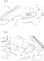
figure 4 is a perspective view of another detail of the car access assembly; -
figure 5 is a perspective view of the support plate on which are mounted a flexible circuit board and two strain gauges; -
figure 6 is a perspective view of the support plate and a structural support of the vehicle. - In the following detailed description of the figures defined above, the same elements or the elements that are fulfilling identical functions may retain the same references so as to simplify the understanding of the invention.
- As illustrated in
figures 1 to 6 , acar access assembly 1 comprises asupport blade 3 extending according to abasis plane 5, thesupport blade 3 being configured to be mounted on astructural support 7 of a vehicle door. - The
car access assembly 1 comprises amain strain gauge 9 mounted on thesupport blade 3 and configured to measure, within thebasis plane 5, an elongation or a contraction of themain strain gauge 9 according to amain direction 11. - The
car access assembly 1 comprises anadditional strain gauge 13 mounted on thesupport blade 3 in such a way to extend, at least partially, in an inclined manner with respect to thebasis plane 5. Theadditional strain gauge 13 is configured to measure an elongation or a contraction of theadditional strain gauge 13. - The
car access assembly 1 comprises ahandle cover 15 configured to be mounted around thesupport blade 3, themain strain gauge 9 and theadditional strain gauge 13. - As illustrated on
figures 1 and 2 , thehandle cover 15 presents amain actuating area 17 configured to be manually actuated according to or parallel to themain direction 11 for triggering themain strain gauge 9 and anadditional actuating area 19 configured to be manually actuated according to or parallel to anadditional direction 21, which is transverse to themain direction 11, for triggering theadditional strain gauge 13. - As illustrated in
figure 3 , thehandle cover 15 is provided with amain transmission part 23 that is in contact with thesupport blade 3 in a region of thesupport blade 3 which is aligned or merged with themain strain gauge 9 location according to themain direction 11. - The
main transmission part 23 is configured to apply a strain on thesupport blade 3 in such a way to elongate or contract themain strain gauge 9 according to themain direction 11 when themain actuating area 17 is manually actuated according to or parallel to themain direction 11. - This establishes a connection between the manual action of a user on the
main actuating area 17 according to themain direction 11 and the triggering of themain stain gauge 9. - Indeed, as the
support blade 3 is mounted on thestructural support 7 of the vehicle door, it appears that thesupport blade 3 is maintained in position by thestructural support 7 whereas thehandle cover 15 is loaded by the user hand. There is therefore a need for a cooperation between thesupport blade 3 and thehandle cover 15 that facilitates the triggering of themain strain gauge 9 to obtain a reliable command. - The
main transmission part 23 is a pin extending from thehandle cover 15. Said pin extends transversally to thebasis plane 5 when thehandle cover 15 is mounted around thesupport blade 3. - The
main transmission part 23 is here distant from themain strain gauge 9 according to themain direction 11. In this case, themain transmission part 23 cooperates with a face of thesupport blade 3 on which is located themain strain gauge 9. - The
main strain gauge 9 extends in a planar way in parallel to thebasis plane 5. - As illustrated in
figure 4 , thehandle cover 15 is provided with anadditional transmission part 25 that is in contact with thesupport blade 3 in a region of thesupport blade 3 which is aligned or merged with theadditional strain gauge 13 location according to theadditional direction 21. - The
additional transmission part 25 is configured to apply a strain on thesupport blade 3 in such a way to elongate or contract theadditional strain gauge 13 when theadditional actuating area 19 is manually actuated according to or parallel to theadditional direction 21. - This links the manual action of a user on the
additional actuating area 19 according to theadditional direction 21 to the triggering of theadditional stain gauge 13. - The
additional transmission part 25 is a pin extending from thehandle cover 15. - The
additional transmission part 25 cooperates with an opposed face of thesupport blade 3 which is on the other side of the face on which theadditional strain gauge 13 is located. In this case, theadditional transmission part 25 is under theadditional strain gauge 13. - As illustrated in
figure 1 , thehandle cover 15 comprises anupper cover 27 and a lower cover 29 configured to cooperate, for example by including each a corresponding part of a snap-in mechanism. Theupper cover 27 includes themain transmission part 23 and the lower cover 29 includes theadditional transmission part 25. - The
additional strain gauge 13 extends at least partially in a curved way. This enables to trigger theadditional strain gauge 13 not only according to theadditional direction 21 but also according to other directions that are tangential to the curvature of theadditional strain gauge 13. - The perceived signal according to these other directions is more or less important depending on the curvature of the
additional strain gauge 13. - The combined effect of the
main strain gauge 9 and theadditional strain gauge 13 is to capture three dimensional efforts and to eventually filter out what could be a misuse case or a solicitation coming from an undesired direction not associated with the principal function. - Indeed, it becomes apparent if only the
main strain gauge 9 or only theadditional strain gauge 13 is triggered or both at same time. The strength of the signal engendered by theadditional strain gauge 13 also tells according which direction the actuation comes. - A strong or relevant signal is received for an actuation according to the
additional direction 21 whereas theadditional strain gauge 13 can be curved in such a way as to receive weaker signals for the other directions. - In case a misuse is detected, because both the
main strain gauge 9 and theadditional strain gauge 13 are actuated together, the signals can be considered as unintentional. - The
additional strain gauge 13 comprises aportion 31 extending according to thebasis plane 5. It allows to detect, in addition to the signal from themain strain gauge 9, an effort applied by the user according to a direction within thebasis plane 5. - Typically, this could be helpful to distinguish between a user applying an effort on the
main actuating area 17 according to themain direction 11 and a user gripping the handle or using the handle as a hook for a bag. - Combining the signals from the
main strain gauge 9 and from theadditional strain gauge 13 helps determining more precisely the user command. - The
portion 31 of theadditional strain gauge 13 extending according to thebasis plane 5 is parallel to themain direction 11. - Thus, said
portion 31 is oriented to detect within thebasis plane 5 an elongation or contraction parallel to themain direction 11. - As an example, this provision is helpful to detect if a user is really trying to actuate the
main actuating area 17. If the signal received by themain strain gauge 9 and the signal received by theadditional strain gauge 13 both correspond to an elongation and if the signal from themain strain gauge 9 is more relevant or stronger, it could lead to the conclusion that the command is correct. - Conversely, if the
additional strain gauge 13 signal is more relevant or stronger, it possibly means that there is a misuse and that the handle cover is actuated in areas that are not appropriate. - Naturally, depending on the geometry of the
car access assembly 1, the positions and sensitivities of the sensors, other interpretation of both signals could be done. - The
support blade 3 includes anadditional extension fraction 33 which extends, at least partially, in an inclined manner with respect to thebasis plane 5; theadditional strain gauge 13 being at least partially mounted on saidadditional extension fraction 33. - The at least partial inclined extension of the
additional strain gauge 13 is defined by the geometry of theadditional extension fraction 33 with respect to thebasis plane 5. - In other words, the
support blade 3 mainly extends according to thebasis plane 5 but also has anadditional extension fraction 33 which is oriented differently. This provision enables to easily mount theadditional strain gauge 13 on thesupport blade 3 with the right orientation. - As illustrated in
figures 5 and 6 , thecar access assembly 1 includes aflexible circuit board 35 configured to be installed on thesupport blade 3 and to receive themain strain gauge 9 and theadditional strain gauge 13. - In other words, the
flexible circuit board 35 is placed between thesupport blade 3 on one side and themain strain gauge 9 andadditional strain gauge 13 on the other side. - The
flexible circuit board 35 comprises aconnection section 37 configured to be connected to a controllingassembly 39 of the vehicle. - The
support blade 3 presents a throughopening 41 for the passage of theconnection section 37. The controllingassembly 39 of the vehicle is mounted on thestructural support 7. - The
car access assembly 37 is provided with afixation mechanism 43 for being mounted on a corresponding arrangement of thestructural support 7. For example, saidfixation mechanism 43 comprises screws and guiding openings for the screws within thesupport blade 3. - The
support blade 3 includes amain extension fraction 45 which extends, at least partially, in an inclined manner with respect to thebasis plane 5; themain strain gauge 9 being aligned with saidmain extension fraction 45 according to themain direction 11. - As illustrated in
figure 2 , functionally, thehandle cover 15 comprises abasis fraction 47 extending according to thebasis plane 5 and encompassing at least partially thesupport blade 3. - The
handle cover 15 also comprises anactuating fraction 49 linked to thebasis fraction 47 and extending transversally to thebasis fraction 47, the actuatingfraction 49 including themain actuating area 17 and theadditional actuating area 19 so as to be capable of being actuated according to or parallel to themain direction 11 and theadditional direction 21. - The actuating
fraction 49 presents amain edge 51 extending parallel to thebasis plane 5 and transversally to themain direction 11 so as to define themain actuating area 17. - The
actuation fraction 49 also presents anadditional edge 53 extending transversally to themain edge 51 and oriented toward thebasis fraction 47 so as to define theadditional actuating area 19. - The
handle cover 15 presents a wing form, the transversal part defined by theadditional edge 53 being and the straight part defined by themain edge 51. - The actuating
fraction 49 starting from themain edge 51 is manually operable by a user in parallel to themain direction 11. From the user perspective, a first function is associated when pushing and a second function is associated when pulling. - The actuating
fraction 49 starting from theadditional edge 53 is manually operable by a user transversally to the direction of theadditional edge 53. The user can tap or press theadditional edge 53 to actuate a third function. Said direction extending transversally to theadditional edge 53 corresponds to theadditional direction 21. - The first function can be an automatic opening command of the vehicle door. The second function can be the opening of the vehicle door so that the user can pull the car door by hand. The third function can be locking and unlocking the vehicle.
- The functions can also be reprogrammed by the user thanks to the controlling
assembly 39 of the vehicle. - As illustrated in
figures 5 and 6 , the actuatingfraction 49 can include anoptional sensing unit 55 configured to be linked to a dedicated part of theflexible circuit board 35. - The
optional sensing unit 55 is then used as redundant sensor(s) to improve the filtering of the signals. Theoptional sensing unit 55 can include for example a capacitive sensor. - The
optional sensing unit 55 can also include a led module, a NFC approach sensor and/or a light guide or courtesy light. - The
car access assembly 1 comprises a resin configured to fill the gaps between the handle cover and the rest of the inner elements of thecar access assembly 1. This works like a protection glove that renders thecar access assembly 1 tight and resistant. - The obtained vehicle door comprises the
structural support 7 and thecar access assembly 1 as described, thesupport blade 3 being mounted on thestructural support 7 of the vehicle door, saidstructural support 7 being part of or being mounted on a pillar of the vehicle door. - As the
main strain gauge 9 and theadditional strain gauge 13 can be placed in proximity from each other within thehandle cover 15, there is no difficulty to install thecar access assembly 1 on the vehicle pillar. In particular, said pillar corresponds to B-pillar or C-pillar. - A vehicle can then comprise several vehicle doors as described above.
- The described vehicle handles have different commands integrated in a small place and can have a clean design. Indeed, the respective orientations of the
main strain gauge 9 and theadditional strain gauge 13 facilitate the interpretation of the measured signals. There is less risk to have measured signals that could lead to a doubt of the actuating area which is really used. - As goes without saying, the invention is not limited to the sole embodiment described above by way of example, it encompasses all the variants.
Claims (13)
- Car access assembly (1) comprising :- a support blade (3) extending according to a basis plane (5), the support blade (3) being configured to be mounted on a structural support (7) of a vehicle door,- a main strain gauge (9) mounted on the support blade (3) and configured to measure, within the basis plane (5), an elongation or a contraction of the main strain gauge (9) according to a main direction (11),- an additional strain gauge (13) mounted on the support blade (3) in such a way to extend, at least partially, in an inclined manner with respect to the basis plane (5), the additional strain gauge (13) being configured to measure an elongation or a contraction of the additional strain gauge (13),- a handle cover (15) configured to be mounted around the support blade (3), the main strain gauge (9) and the additional strain gauge (13); the handle cover (15) presenting a main actuating area (17) configured to be manually actuated according to or parallel to the main direction (11) for triggering the main strain gauge (9) and an additional actuating area (19) configured to be manually actuated according to or parallel to an additional direction (21), which is transverse to the main direction (11), for triggering the additional strain gauge (13).
- Car access assembly (1) according to claim 1, wherein the handle cover (15) is provided with a main transmission part (23) that is in contact with the support blade (3) in a region of the support blade (3) which is aligned or merged with the main strain gauge (9) location according to the main direction (11), the main transmission part (23) being configured to apply a strain on the support blade (3) in such a way to elongate or contract the main strain gauge (9) according to the main direction (11) when the main actuating area (17) is manually actuated according to or parallel to the main direction (11).
- Car access assembly (1) according to one of the claims 1 or 2, wherein the main strain gauge (9) extends in a planar way in parallel to the basis plane (5).
- Car access assembly (1) according to one of the claims 1 to 3, wherein the handle cover (15) is provided with an additional transmission part (25) that is in contact with the support blade (3) in a region of the support blade (3) which is aligned or merged with the additional strain gauge (13) location according to the additional direction (21), the additional transmission part (25) being configured to apply a strain on the support blade (3) in such a way to elongate or contract the additional strain gauge (13) when the additional actuating area (19) is manually actuated according to or parallel to the additional direction (21).
- Car access assembly (1) according to one of the claims 1 to 4, wherein the additional strain gauge (13) extends at least partially in a curved way.
- Car access assembly (1) according to claim 5, wherein the additional strain gauge (13) comprises a portion (31) extending according to the basis plane (5).
- Car access assembly (1) according to claim 6, wherein the portion (31) of the additional strain gauge (13) extending according to the basis plane (5) is parallel to the main direction (11).
- Car access assembly (1) according to one of the claims 1 to 7, wherein the support blade (3) includes an additional extension fraction (33) which extends, at least partially, in an inclined manner with respect to the basis plane (5); the additional strain gauge (13) being at least partially mounted on said additional extension fraction (33).
- Car access assembly (1) according to one of the claims 1 to 8, including a flexible circuit board (35) configured to be installed on the support blade (3) and to receive the main strain gauge (9) and the additional strain gauge (13).
- Car access assembly (1) according to one of the claims 1 to 9, wherein the support blade (3) includes a main extension fraction (45) which extends, at least partially, in an inclined manner with respect to the basis plane (5); the main strain gauge (9) being aligned with said main extension fraction (45) according to the main direction (11).
- Car access assembly (1) according to one of the claims 1 to 10, wherein the handle cover (15) comprises:- a basis fraction (47) extending according to the basis plane (5) and encompassing at least partially the support blade (3) and- an actuating fraction (49) linked to the basis fraction (47) and extending transversally to the basis fraction (47), the actuating fraction (49) including the main actuating area (17) and the additional actuating area (19) so as to be capable of being actuated according to or parallel to the main direction (11) and the additional direction (21).
- Car access assembly (1) according to claim 11, wherein the actuating fraction (49) presents a main edge (51) extending parallel to the basis plane (5) and transversally to the main direction (11) so as to define the main actuating area (17); and wherein the actuation fraction (49) presents an additional edge (53) extending transversally to the main edge (51) and oriented toward the basis fraction (47) so as to define the additional actuating area (19).
- Vehicle door comprising the structural support (7) and the car access assembly (1) to one of the claims 1 to 12, the support blade (3) being mounted on the structural support (7) of the vehicle door, said structural support (7) being part of or being mounted on a pillar of the vehicle door.
Priority Applications (5)
| Application Number | Priority Date | Filing Date | Title |
|---|---|---|---|
| ES23192702T ES3063511T3 (en) | 2023-08-22 | 2023-08-22 | Car access assembly with two strain gauges oriented differently |
| EP23192702.1A EP4512982B1 (en) | 2023-08-22 | 2023-08-22 | Car access assembly with two strain gauges oriented differently |
| US18/808,867 US20250067092A1 (en) | 2023-08-22 | 2024-08-19 | Car access assembly with two strain gauges oriented differently |
| CN202411151339.1A CN119507751A (en) | 2023-08-22 | 2024-08-21 | Car access assembly with two strain gauges having different orientations |
| JP2024139424A JP2025031644A (en) | 2023-08-22 | 2024-08-21 | Car access assembly with two sets of strain gauges mounted in different orientations |
Applications Claiming Priority (1)
| Application Number | Priority Date | Filing Date | Title |
|---|---|---|---|
| EP23192702.1A EP4512982B1 (en) | 2023-08-22 | 2023-08-22 | Car access assembly with two strain gauges oriented differently |
Publications (2)
| Publication Number | Publication Date |
|---|---|
| EP4512982A1 true EP4512982A1 (en) | 2025-02-26 |
| EP4512982B1 EP4512982B1 (en) | 2025-12-03 |
Family
ID=87762898
Family Applications (1)
| Application Number | Title | Priority Date | Filing Date |
|---|---|---|---|
| EP23192702.1A Active EP4512982B1 (en) | 2023-08-22 | 2023-08-22 | Car access assembly with two strain gauges oriented differently |
Country Status (5)
| Country | Link |
|---|---|
| US (1) | US20250067092A1 (en) |
| EP (1) | EP4512982B1 (en) |
| JP (1) | JP2025031644A (en) |
| CN (1) | CN119507751A (en) |
| ES (1) | ES3063511T3 (en) |
Citations (3)
| Publication number | Priority date | Publication date | Assignee | Title |
|---|---|---|---|---|
| US20030101781A1 (en) * | 1999-11-29 | 2003-06-05 | Edgar Budzynski | Motor vehicle door lock system |
| US20140292004A1 (en) * | 2013-04-01 | 2014-10-02 | Magna Mirrors Of America, Inc. | Vehicle door handle system |
| JP2016130392A (en) * | 2015-01-13 | 2016-07-21 | パナソニックIpマネジメント株式会社 | Door handle |
Family Cites Families (7)
| Publication number | Priority date | Publication date | Assignee | Title |
|---|---|---|---|---|
| JP4970143B2 (en) * | 2007-05-28 | 2012-07-04 | 株式会社フジクラ | Door opener |
| US20160251880A1 (en) * | 2013-03-15 | 2016-09-01 | Adac Plastic, Inc. | Control for vehicle closures |
| JP6251939B2 (en) * | 2014-04-10 | 2017-12-27 | 株式会社ホンダロック | Detection device and door handle device |
| US20180058837A1 (en) * | 2016-08-24 | 2018-03-01 | Knowles Electronics, Llc | User interface incorporating strain gauges |
| DE102018113946A1 (en) * | 2018-06-12 | 2019-12-12 | HELLA GmbH & Co. KGaA | Bending printed circuit boards |
| EP4155487A1 (en) * | 2021-09-23 | 2023-03-29 | U-Shin Italia S.p.A. | Detection device and detection system for activating at least on function of an apparatus, and apparatus comprising the detection system |
| DE102023105204A1 (en) * | 2023-03-02 | 2024-09-05 | Bayerische Motoren Werke Aktiengesellschaft | External handle for a wing element for a vehicle, arrangement of an external handle on a wing element for a vehicle and vehicle |
-
2023
- 2023-08-22 EP EP23192702.1A patent/EP4512982B1/en active Active
- 2023-08-22 ES ES23192702T patent/ES3063511T3/en active Active
-
2024
- 2024-08-19 US US18/808,867 patent/US20250067092A1/en active Pending
- 2024-08-21 CN CN202411151339.1A patent/CN119507751A/en active Pending
- 2024-08-21 JP JP2024139424A patent/JP2025031644A/en active Pending
Patent Citations (3)
| Publication number | Priority date | Publication date | Assignee | Title |
|---|---|---|---|---|
| US20030101781A1 (en) * | 1999-11-29 | 2003-06-05 | Edgar Budzynski | Motor vehicle door lock system |
| US20140292004A1 (en) * | 2013-04-01 | 2014-10-02 | Magna Mirrors Of America, Inc. | Vehicle door handle system |
| JP2016130392A (en) * | 2015-01-13 | 2016-07-21 | パナソニックIpマネジメント株式会社 | Door handle |
Also Published As
| Publication number | Publication date |
|---|---|
| US20250067092A1 (en) | 2025-02-27 |
| CN119507751A (en) | 2025-02-25 |
| ES3063511T3 (en) | 2026-04-16 |
| JP2025031644A (en) | 2025-03-07 |
| EP4512982B1 (en) | 2025-12-03 |
Similar Documents
| Publication | Publication Date | Title |
|---|---|---|
| JP7618544B2 (en) | SENSOR SYSTEM FOR A MOVING PART OF A VEHICLE AND METHOD FOR DETECTING ACTIVATION OF A SENSOR SYSTEM - Patent application | |
| US7091836B2 (en) | Motor vehicle door locking system and door handle | |
| CN107849875A (en) | Door outer handle for vehicle | |
| US8454062B2 (en) | Handle device | |
| JP6717912B2 (en) | Outer door handle mechanism for automobile | |
| US20030029210A1 (en) | Exterior door handle system | |
| EP2372055A1 (en) | Door courtesy switch abnormality detection apparatus and method | |
| EP3835519B1 (en) | Motorized door leaf handle for a motor vehicle | |
| US20070227203A1 (en) | Device for Actuating an Electrical or Mechanical Closure Mechanism on a Vehicle Door and/or Shutter | |
| EP2230367A2 (en) | Door handle apparatus for vehicle | |
| EP1245761A2 (en) | Vehicle outer handle system | |
| US20190048645A1 (en) | Vehicle door opening/closing control device | |
| US20070126246A1 (en) | Vehicle door opening/closing device | |
| EP4512982A1 (en) | Car access assembly with two strain gauges oriented differently | |
| WO2017009076A1 (en) | Exterior door handle for a vehicle | |
| EP4336003B1 (en) | Car access assembly comprising electronic sensing unit for a handle attached on a car door | |
| US20020149262A1 (en) | Motor-vehicle door locking system with quick unlocking | |
| DE102005061755A1 (en) | Method for operating a motor vehicle door lock has a fixed handle housing a capacitive sensor electrode and electronic identification system and a piezo electric sensor to release the lock upon authorised identification | |
| US20260055647A1 (en) | Vehicle Door for a Motor Vehicle, in Particular for a Passenger Car, and Motor Vehicle | |
| EP4336004B1 (en) | Car access assembly comprising a handle of a car door | |
| JP2024035826A (en) | Handle with strain gauge module used as sensor for car door | |
| DE102004045152A1 (en) | Control mechanism for door of motor vehicle, has locking operation units to release locking of vehicle door and arranged on unit e.g. cover of cylinder lock, which is separated from door handle | |
| CN116733318A (en) | Actuating mechanism for actuating vehicle doors | |
| CN108533095B (en) | door control device | |
| KR20160019620A (en) | Cable connecting apparatus of trunk lid latch for vehicles |
Legal Events
| Date | Code | Title | Description |
|---|---|---|---|
| PUAI | Public reference made under article 153(3) epc to a published international application that has entered the european phase |
Free format text: ORIGINAL CODE: 0009012 |
|
| STAA | Information on the status of an ep patent application or granted ep patent |
Free format text: STATUS: REQUEST FOR EXAMINATION WAS MADE |
|
| 17P | Request for examination filed |
Effective date: 20230822 |
|
| AK | Designated contracting states |
Kind code of ref document: A1 Designated state(s): AL AT BE BG CH CY CZ DE DK EE ES FI FR GB GR HR HU IE IS IT LI LT LU LV MC ME MK MT NL NO PL PT RO RS SE SI SK SM TR |
|
| GRAP | Despatch of communication of intention to grant a patent |
Free format text: ORIGINAL CODE: EPIDOSNIGR1 |
|
| STAA | Information on the status of an ep patent application or granted ep patent |
Free format text: STATUS: GRANT OF PATENT IS INTENDED |
|
| INTG | Intention to grant announced |
Effective date: 20250714 |
|
| RIC1 | Information provided on ipc code assigned before grant |
Ipc: E05B 81/76 20140101AFI20250704BHEP Ipc: H03K 17/94 20060101ALI20250704BHEP |
|
| GRAS | Grant fee paid |
Free format text: ORIGINAL CODE: EPIDOSNIGR3 |
|
| GRAA | (expected) grant |
Free format text: ORIGINAL CODE: 0009210 |
|
| STAA | Information on the status of an ep patent application or granted ep patent |
Free format text: STATUS: THE PATENT HAS BEEN GRANTED |
|
| AK | Designated contracting states |
Kind code of ref document: B1 Designated state(s): AL AT BE BG CH CY CZ DE DK EE ES FI FR GB GR HR HU IE IS IT LI LT LU LV MC ME MK MT NL NO PL PT RO RS SE SI SK SM TR |
|
| REG | Reference to a national code |
Ref country code: CH Ref legal event code: F10 Free format text: ST27 STATUS EVENT CODE: U-0-0-F10-F00 (AS PROVIDED BY THE NATIONAL OFFICE) Effective date: 20251203 Ref country code: GB Ref legal event code: FG4D |
|
| REG | Reference to a national code |
Ref country code: DE Ref legal event code: R096 Ref document number: 602023009203 Country of ref document: DE |
|
| REG | Reference to a national code |
Ref country code: IE Ref legal event code: FG4D |
|
| REG | Reference to a national code |
Ref country code: NL Ref legal event code: MP Effective date: 20251203 |
|
| REG | Reference to a national code |
Ref country code: LT Ref legal event code: MG9D |
|
| PG25 | Lapsed in a contracting state [announced via postgrant information from national office to epo] |
Ref country code: NO Free format text: LAPSE BECAUSE OF FAILURE TO SUBMIT A TRANSLATION OF THE DESCRIPTION OR TO PAY THE FEE WITHIN THE PRESCRIBED TIME-LIMIT Effective date: 20260303 |
|
| PG25 | Lapsed in a contracting state [announced via postgrant information from national office to epo] |
Ref country code: HR Free format text: LAPSE BECAUSE OF FAILURE TO SUBMIT A TRANSLATION OF THE DESCRIPTION OR TO PAY THE FEE WITHIN THE PRESCRIBED TIME-LIMIT Effective date: 20251203 Ref country code: FI Free format text: LAPSE BECAUSE OF FAILURE TO SUBMIT A TRANSLATION OF THE DESCRIPTION OR TO PAY THE FEE WITHIN THE PRESCRIBED TIME-LIMIT Effective date: 20251203 |
|
| REG | Reference to a national code |
Ref country code: ES Ref legal event code: FG2A Ref document number: 3063511 Country of ref document: ES Kind code of ref document: T3 Effective date: 20260416 |
|
| PG25 | Lapsed in a contracting state [announced via postgrant information from national office to epo] |
Ref country code: RS Free format text: LAPSE BECAUSE OF FAILURE TO SUBMIT A TRANSLATION OF THE DESCRIPTION OR TO PAY THE FEE WITHIN THE PRESCRIBED TIME-LIMIT Effective date: 20260303 |
|
| PG25 | Lapsed in a contracting state [announced via postgrant information from national office to epo] |
Ref country code: PL Free format text: LAPSE BECAUSE OF FAILURE TO SUBMIT A TRANSLATION OF THE DESCRIPTION OR TO PAY THE FEE WITHIN THE PRESCRIBED TIME-LIMIT Effective date: 20251203 |
|
| PG25 | Lapsed in a contracting state [announced via postgrant information from national office to epo] |
Ref country code: LV Free format text: LAPSE BECAUSE OF FAILURE TO SUBMIT A TRANSLATION OF THE DESCRIPTION OR TO PAY THE FEE WITHIN THE PRESCRIBED TIME-LIMIT Effective date: 20251203 |