EP4512884A1 - Cell transfer apparatus - Google Patents
Cell transfer apparatus Download PDFInfo
- Publication number
- EP4512884A1 EP4512884A1 EP22944051.6A EP22944051A EP4512884A1 EP 4512884 A1 EP4512884 A1 EP 4512884A1 EP 22944051 A EP22944051 A EP 22944051A EP 4512884 A1 EP4512884 A1 EP 4512884A1
- Authority
- EP
- European Patent Office
- Prior art keywords
- suction
- container
- cells
- head
- cell
- Prior art date
- Legal status (The legal status is an assumption and is not a legal conclusion. Google has not performed a legal analysis and makes no representation as to the accuracy of the status listed.)
- Pending
Links
Images






Classifications
-
- C—CHEMISTRY; METALLURGY
- C12—BIOCHEMISTRY; BEER; SPIRITS; WINE; VINEGAR; MICROBIOLOGY; ENZYMOLOGY; MUTATION OR GENETIC ENGINEERING
- C12M—APPARATUS FOR ENZYMOLOGY OR MICROBIOLOGY; APPARATUS FOR CULTURING MICROORGANISMS FOR PRODUCING BIOMASS, FOR GROWING CELLS OR FOR OBTAINING FERMENTATION OR METABOLIC PRODUCTS, i.e. BIOREACTORS OR FERMENTERS
- C12M33/00—Means for introduction, transport, positioning, extraction, harvesting, peeling or sampling of biological material in or from the apparatus
- C12M33/04—Means for introduction, transport, positioning, extraction, harvesting, peeling or sampling of biological material in or from the apparatus by injection or suction, e.g. using pipettes, syringes, needles
- C12M33/06—Means for introduction, transport, positioning, extraction, harvesting, peeling or sampling of biological material in or from the apparatus by injection or suction, e.g. using pipettes, syringes, needles for multiple inoculation or multiple collection of samples
-
- C—CHEMISTRY; METALLURGY
- C12—BIOCHEMISTRY; BEER; SPIRITS; WINE; VINEGAR; MICROBIOLOGY; ENZYMOLOGY; MUTATION OR GENETIC ENGINEERING
- C12M—APPARATUS FOR ENZYMOLOGY OR MICROBIOLOGY; APPARATUS FOR CULTURING MICROORGANISMS FOR PRODUCING BIOMASS, FOR GROWING CELLS OR FOR OBTAINING FERMENTATION OR METABOLIC PRODUCTS, i.e. BIOREACTORS OR FERMENTERS
- C12M23/00—Constructional details, e.g. recesses, hinges
- C12M23/02—Form or structure of the vessel
- C12M23/12—Well or multiwell plates
-
- C—CHEMISTRY; METALLURGY
- C12—BIOCHEMISTRY; BEER; SPIRITS; WINE; VINEGAR; MICROBIOLOGY; ENZYMOLOGY; MUTATION OR GENETIC ENGINEERING
- C12M—APPARATUS FOR ENZYMOLOGY OR MICROBIOLOGY; APPARATUS FOR CULTURING MICROORGANISMS FOR PRODUCING BIOMASS, FOR GROWING CELLS OR FOR OBTAINING FERMENTATION OR METABOLIC PRODUCTS, i.e. BIOREACTORS OR FERMENTERS
- C12M41/00—Means for regulation, monitoring, measurement or control, e.g. flow regulation
- C12M41/30—Means for regulation, monitoring, measurement or control, e.g. flow regulation of concentration
- C12M41/36—Means for regulation, monitoring, measurement or control, e.g. flow regulation of concentration of biomass, e.g. colony counters or by turbidity measurements
-
- C—CHEMISTRY; METALLURGY
- C12—BIOCHEMISTRY; BEER; SPIRITS; WINE; VINEGAR; MICROBIOLOGY; ENZYMOLOGY; MUTATION OR GENETIC ENGINEERING
- C12M—APPARATUS FOR ENZYMOLOGY OR MICROBIOLOGY; APPARATUS FOR CULTURING MICROORGANISMS FOR PRODUCING BIOMASS, FOR GROWING CELLS OR FOR OBTAINING FERMENTATION OR METABOLIC PRODUCTS, i.e. BIOREACTORS OR FERMENTERS
- C12M47/00—Means for after-treatment of the produced biomass or of the fermentation or metabolic products, e.g. storage of biomass
- C12M47/04—Cell isolation or sorting
Definitions
- the present invention relates to a cell transfer apparatus for transferring cells scattered in one container to another container.
- a cell transfer apparatus uses a head to which a suction tip is attached to perform the operation of suctioning one target cell from the sorting container and discharging the suctioned target cell into a well of the work container.
- Patent Literature 1 discloses a target object observation device equipped with a suction tip that can suction and hold multiple cells. However, Patent Literature 1 assumes the use of a suction tip with a special shape having a cell trap part with a horizontal part.
- An object of the present invention is to provide a cell transfer apparatus that can efficiently transfer multiple cells scattered in one container to another container.
- the first container 41 includes a rectangular upper opening 11H on the upper surface side.
- the upper opening 11H is an opening for injecting the cells C and picking up the sorted cells C.
- the injection of the cells C is a step of discharging a cell suspension containing a large amount of cells C from a dispenser tip (not shown).
- the pickup of the cells C is performed by the suction tip 1 described above.
- the dish 43 is placed below the upper opening 11H.
- the first container 41 and the dish 43 are produced using a translucent resin material or glass. This is to allow the camera unit 5 placed below the first container 41 to observe the cells C carried in the dish 43.
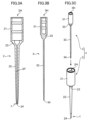
- FIG. 2 is a cross-sectional view of the suction tip 1.
- FIG. 3A is a cross-sectional view of a syringe 2
- FIG. 3B is a cross-sectional view of a plunger 3
- FIG. 3C is an exploded perspective view of the suction tip 1.
- the suction tip 1 includes the syringe 2 with a tubular passage 2P that serves as a suction path for the cells C, and the plunger 3 that is slidably accommodated inside the tubular passage 2P.
- the plunger 3 is a member that is inserted into the tubular passage 2P of the syringe 2 and generates negative pressure for cell suction or positive pressure for cell discharge in the distal end opening 24 by moving back and forth inside the tubular passage 2P.
- the plunger 3 includes a plunger proximal end 31 having a cylindrical shape, a needle-shaped plunger body 32, a dome-shaped part 33 connecting the proximal end 31 and the body 32, and a plunger distal end 34 that is a protruding end of the plunger body 32.
- the syringe proximal end 21 includes a cylindrical hollow part 2H.
- the outer diameter of the plunger proximal end 31 is set to be smaller than the inner diameter of the hollow part 2H by a predetermined length.
- the outer diameter of the plunger body 32 is set to be slightly smaller than the inner diameter of the tubular passage 2P.
- the shape of the inner circumferential surface of the taper cylinder part 23 matches the curved surface shape of the outer circumferential surface of the dome-shaped part 33.
- the plunger 3 is assembled with respect to the syringe 2 in a mode in which the plunger proximal end 31 is accommodated in the hollow part 2H, and the plunger body 32 is inserted into the tubular passage 2P of the syringe body 22.
- FIG. 3C shows the state where the plunger 3 is pulled out from the syringe 2
- FIG. 2 shows the state where the plunger body 32 is inserted deepest into the syringe body 22, that is, the state where the plunger 3 has descended the most.
- the dome-shaped part 33 is completely accommodated in the cavity of the taper cylinder part 23.
- the length of the plunger body 32 is slightly longer than the syringe body 22, and in the state shown in FIG. 2 , the plunger distal end 34 protrudes from the distal end opening 24.
- the plunger 3 can move upward with respect to the syringe 2 from the state shown in FIG. 2 .
- the plunger distal end 34 will be submerged inside the tubular passage 2P.
- suction force is generated in the distal end opening 24, and the fluid around the distal end opening 24, the culture medium L including the cells C in the present embodiment can be suctioned into the tubular passage 2P.
- the fluid suctioned into the tubular passage 2P can be discharged from the distal end opening 24.
- the suction tip 1 is attached to the distal end of the head 61 shown in FIG. 2 .
- the head 61 includes a first cylindrical rod 611, a second cylindrical rod 612 placed outside of the first cylindrical rod 611, and a plunger rod 613 (generating mechanism/moving member) placed in the hollow part of the first cylindrical rod 611.
- the plunger proximal end 31 includes a mounting hole 3H, a cylindrical hollow space.
- the lower end of the plunger rod 613 is press-fitted into the mounting hole 3H.
- the upper end surface of the plunger proximal end 31 faces the lower end surface of the first cylindrical rod 611.
- the lower end of the fixed second cylindrical rod 612 is press-fitted into the hollow part 2H of the syringe proximal end 21.
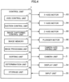
- FIG. 4 is a block diagram showing the electric configuration of the cell transfer apparatus S.
- the cell transfer apparatus S includes a control unit 7 that controls the movement operation of the head unit 6, the suction and discharge operation of the cells C by the suction tip 1, the movement and image capturing operation of the camera unit 5, and the like.
- the cell transfer apparatus S includes a camera axis driving unit 53 as a mechanism for causing the camera unit 5 to horizontally move, an X-axis motor 63 and Y-axis motor 64 as mechanisms for horizontally moving the head unit 6, a Z-axis motor 65 as a mechanism for raising and lowering the head 61, and a plunger motor 66 as a mechanism for performing suction and discharge operations of the cells C, and further includes a display unit 54 and an input unit 55.
- the camera axis driving unit 53 includes a driving motor for causing the camera unit 5 to horizontally move along the guide rail 5G.
- the X-axis motor 63 and the Y-axis motor 64 are driving sources for the movement mechanism that causes the head unit 6 to move horizontally along the guide rail 6G.
- the preferred mode of the movement mechanism includes ball screws and nut members for the X axis and Y axis, and the X-axis motor 63 and the Y-axis motor 64 each rotate the ball screw forward or backward.
- the Z-axis motor 65 and the plunger motor 66 are built into the head body 62.
- the Z-axis motor 65 causes the head 61 to move up and down between the lowered position where the head 61 extends downward from the head body 62 and the raised position where most of the head 61 is accommodated in the head body 62.
- the plunger motor 66 generates suction force and discharge force in the distal end opening 24 of the suction tip 1 by raising and lowering the plunger rod 613 placed in the head 61 ( FIG. 2 ).
- the display unit 54 includes a liquid crystal display or the like, and displays images captured by the camera unit 5 and images that undergo image processing or the like by the control unit 7.
- the control unit 7 includes a processor or the like that performs various arithmetic processes, and includes an axis control unit 71 (part of the movement mechanism), a suction control unit 72, an image capturing control unit 73, an image memory 74, an image processing unit 75 (part of the cell recognition unit), a sorting unit 76, a determination unit 77, and a storage unit 78.
- the axis control unit 71 controls the operation of the X-axis motor 63 and the Y-axis motor 64 to cause the head unit 6 to move to a predetermined horizontal target position.
- the movement of the head 61 to which the suction tip 1 is attached between the first container 41 and the second container 42, positioning perpendicularly above the accommodation sections 44 of the dish 43, positioning perpendicularly above the well 45 of the second container 42 where discharge is performed, and the like are implemented by controlling the X-axis motor 63 and the Y-axis motor 64 by the axis control unit 71.
- the suction control unit 72 controls the operation of the Z-axis motor 65 and the plunger motor 66 to perform the suction and discharge operation of the cells C by the suction tip 1.
- the suction control unit 72 controls the operation of the Z-axis motor 65 to raise and lower the head 61 to be controlled toward a predetermined target position.
- the suction control unit 72 controls the operation of the plunger motor 66 equipped on the head 61 to be controlled to generate suction force or discharge force in the distal end opening 24 of the suction tip 1 at a predetermined timing.
- the suction control unit 72 performs an operation of gradually suctioning the set quantity of the target cells C that is set to two or more in advance from among the cells C scattered on the dish 43 of the first container 41 into one suction tip 1.
- the set quantity is a quantity received in the input unit 55 from the user.
- the suction control unit 72 performs an operation of discharging the set quantity of the target cells C suctioned by the suction tip 1 into the same location in the second container 42, that is, one well 45.
- Such control will be described using diagrams later with reference to FIGS. 5 to 7 .
- the image capturing control unit 73 controls the camera axis driving unit 53 to perform the operation of causing the camera unit 5 to move along the guide rail 5G. In addition, the image capturing control unit 73 controls the image capturing operation of the first container 41 or the second container 42 by the camera unit 5.
- the image processing unit 75 performs image processing on image data captured by the camera unit 5 and stored in the image memory 74.
- the image processing unit 75 performs processing to recognize the position on the image of the cells C on the dish 43 based on the image of the dish 43 of the first container 41 after the cells C are dispensed.
- the image processing unit 75 performs processing to recognize the distribution of the cells C, to recognize the size, shape, color tone, and the like of the recognized cells C, and the like by using the image processing technology.
- the axis control unit 71 and the suction control unit 72 control the movement of the head 61 and the suction and discharge of the suction tip 1 based on the position recognition of the cells C, and perform the transfer operation of the cells C.
- the sorting unit 76 performs processing to sort the target cells C to be transferred to the second container 42 from a group of the cells C scattered in the first container 41 based on sorting criteria determined in advance.
- the sorting unit 76 derives the quality evaluation value of the cells C scattered on the dish 43 of the first container 41 based on the image captured by the camera unit 5. Specifically, based on image processing results by the image processing unit 75, for example, the feature amounts of the cell C such as the area or estimated volume of the cell C, the color or pattern of the cell C, and the light intensity when the cell C is fluorescent are extracted.
- the number of cells C accommodated in one accommodation section 44 is also detected as one of the feature amounts. This is because when multiple cells C are accommodated in the accommodation section 44, it is difficult to control the number of cells C suctioned to the suction tip 1, the cells C overlap, making accurate evaluation difficult, and other reasons.
- the sorting unit 76 identifies the cell with the evaluation value exceeding a predetermined threshold as the target cell C. That is, the extracted feature amount of each cell C is compared with a selection criteria parameter that is determined in advance as the range of cells C to be selected, and the target cell C is identified by evaluating whether the cell falls within the range of the selection criteria parameter. Through the processing by the sorting unit 76, only the cell C that is evaluated as having superior quality among the cells C accommodated in the first container 41 can be transferred to the second container 42 as the target cell C.
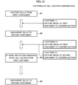
- the determination unit 77 determines whether the suction or discharge of the set quantity of the target cells C is achieved. This determination pattern will be described in detail later with reference to FIG. 13 .
- the storage unit 78 stores various setting values and data in the cell transfer apparatus S. In addition, the storage unit 78 also stores the selection criteria parameter of the cell C to be transferred. The criteria for determining whether the cell C is good or bad may differ depending on the size and type, and, for example, it is preferable to have sorting criteria obtained from results of machine learning for each size and type.
- the sorting unit 76 reads the sorting criteria stored in the storage unit 78 during the sorting process.
- FIGS. 5A to 5D and FIGS. 6A to 6D are diagrams showing the above-mentioned preliminary treatment step (1) and suction step (2).
- FIG. 5A shows the suction tip 1 in a state of holding the preliminary treatment liquid LA in the space between the syringe body 22 and the plunger body 32.
- the preliminary treatment step (1) for example, the distal end t of the syringe 2 is immersed in a container filled with the preliminary treatment liquid LA, and the plunger 3 moves back and forth about three times. This operation brings the preliminary treatment liquid LA into the space between the syringe body 22 and the plunger body 32.
- a physiological saline solution or the like may be used as the preliminary treatment liquid LA, but it is preferable to use the culture medium L.
- FIGS. 5A and 5B are also diagrams showing the step of forming an air layer H inside the tubular passage 2P before performing the suction step (2).
- the suction control unit 72 places the distal end t of the suction tip 1 in the air as shown in FIG. 5A , and drives the plunger motor 66 from the state where the plunger distal end 34 protrudes from the distal end opening 24 of the syringe 2 to raise the plunger 3 by a predetermined length.
- the air layer H is formed in the tubular passage 2P near the distal end opening 24.
- FIGS. 5C to 6D show the execution status of the suction step (2) sequentially.
- the first container 41 is shown in a simplified manner.
- the first cell C1, the second cell C2, and the third cell C3 selected as target cells to be transferred are scattered.
- the set quantity of the target cells 3.
- the position coordinates of each of the cells C1, C2, and C3 are determined.
- the suction control unit 72 causes one suction tip 1 to suction the cells C1, C2, and C3 gradually. At this time, it is determined in what order to suction the cells C1, C2, and C3, that is, how to set the movement route for the head 61. As the movement route, it is preferable to select a route that is the shortest movement distance by referring to the position coordinates of the cells C1, C2, and C3 in order to shorten the tact time.
- the three target cells lined up horizontally are gradually suctioned in the order of the first cell C1, the second cell C2, and the third cell C3.
- the suction control unit 72 drives the plunger motor 66 to raise the plunger 3 by a predetermined distance.
- the distal end opening 24 is depressurized to generate suction force, causing a part of the culture medium L1 and the first cell C1 in the first container 41 to be suctioned from the distal end opening 24 into the tubular passage 2P.
- the first cell C1 will float in the suctioned culture medium L1a.
- FIG. 5D shows the state after the first cell C1 is suctioned.
- FIGS. 8A and 8B are examples of images of the first container 41 having the accommodation sections 44 before and after the cell suction.
- the first container 41 includes the dish 43 having matrix-arrayed accommodation sections 44, and numerous cells C are scattered in the dish 43.
- FIG. 8A it is assumed that, among these cells C, the cells Ca, Cb, and Cc accommodated one by one in the accommodation sections 44a, 44b, and 44c, respectively, are identified as target cells to be suctioned to one suction tip 1.
- the accommodation sections 44a, 44b, and 44c become empty. If the cells Ca, Cb, and Cc remain in the accommodation sections 44a, 44b, and 44c, the suction will be considered a failure. That is, by capturing an image of the first container 41 after the cell suction and confirming the presence of the cells Ca, Cb, and Cc, it is possible to confirm whether the suction of the target cells by the suction tip 1 is successful or not.
- FIG. 8C is an example of an image of the one well 45 after the cell discharge.
- necessary operations such as introducing reagents are performed.
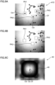
- FIGS. 9A and 9B are examples of images of a first container 410 with a flat bottom having no accommodation sections 44 before and after cell suction. Numerous cells C are scattered in the first container 410. As shown in FIG. 9A , it is assumed that, among the cells C, cells Cd, Ce, and Cf that exist one by one in regions PA1, PA2, and PA3 respectively are identified as target cells to be suctioned into one suction tip 1. In this case as well, a movement route that passes through the regions PA1, PA2, and PA3 in the shortest distance is defined, and the cells Cd, Ce, and Cf are gradually suctioned into one suction tip 1. Whether the suction is successful can be determined, for example, by image matching processing of the pre-suction image in FIG. 9A and the post-suction image in FIG. 9B.
- FIG. 9C is an example of an image after the cells Cd, Ce, and Cf are discharged into one well 45.
- the set quantity of the target cells C in the first container 41 is gradually suctioned into each suction tip 1 attached to the multiple heads 61 included in the head unit 6. Then, the set quantity of the target cells C is discharged all at once from each suction tip 1 into each of the plurality of wells 45 of the second container 42. That is, two or more target cells C held in each suction tip 1 are discharged into the well 45 assigned to each suction tip 1. According to the present embodiment, it is possible to transfer the set quantity of the target cells C from each suction tip 1 to each well 45 of the second container 42 in one movement operation of the head unit 6 from the first container 41 to the second container 42.
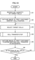
- FIG. 10 is a flowchart showing an operation example of the cell transfer apparatus S.
- the input unit 55 receives the set quantity of the target cells C to be suctioned by one suction tip 1 from the user (step S1).
- the image capturing control unit 73 controls the camera unit 5 to capture an image of the first container 41 before cell suction.
- the image processing unit 75 performs image processing on data of the acquired pre-suction image to identify the position of the cells C scattered in the first container 41 (step S2).
- the sorting unit 76 derives an evaluation value about the quality of the cells C based on the pre-suction image, and identifies the cells with the evaluation value exceeding a predetermined threshold as target cells C to be transferred (step S3).
- the cell transfer step including the above-described preliminary treatment step (1), suction step (2), movement step (3), and discharge step (4) is performed (step S4).
- the image capturing control unit 73 controls the camera unit 5 to capture images of the first container 41 after the cell suction. Then, by comparing the pre-suction image acquired in step S2 with the post-suction image acquired in this step, the determination unit 77 confirms whether the suction of the target cells C is successful, that is, whether the transfer of the target cells is successful (step S5).
- step S6 When all the set quantity of the target cells C is successfully suctioned (YES in step S6), the process ends. On the other hand, when the suction of the target cells C fails partially or completely (NO in step S6), returning to step S3, the cell transfer step for recovery is performed again.
- the determination unit 77 performs processing to determine whether the suction of the target cells C is successful based on the comparison of images of the first container 41 before cell suction and images of the first container 41 after cell suction, or images of the second container 42 after cell discharge (step S36).
- the process for the head 61 this time for example, first head
- the process for the next head 61 for example, second head
- the cell stock unit 81 is a section that stores cell culture solution in which a large amount of cells are dispersed, which is the source of dispensing.
- the cell stock unit 81 includes a tube 811 that is a cylindrical container for storing the cell culture solution containing cells.
- the dispenser tip stock unit 82 is a section that stores a plurality of dispenser tips 821.
- the dispenser tip stock unit 82 is provided with a holder 822 that holds the dispenser tips 821 arranged in a matrix in an upright position.
- the cell sorting unit 83 is a section for sorting cells of a desired size from the cell culture solution containing cells of various sizes.
- the cell sorting unit 83 includes the first container 41 that accommodates the cell culture solution, a holding table 831 that positions and holds the first container 41, and a table lid member 832 that covers an upper surface of the first container 41.
- the first container 41 preferably includes the dish 43, in a similar manner to the first container 41 shown in FIG. 1 .
- An image of the cells carried in the first container 41 is captured by the camera unit 5 under lighting by the lighting unit 56. This identifies the location of the cells to be suctioned.
- the tip image capturing unit 85 is a pit that provides a location where an image of the suction tip 1 attached to the head 61 is captured.
- the image capturing is performed by the camera unit 5.
- the XYZ coordinate position of the distal end opening 24 of the suction tip 1 is obtained.
- a correction value is derived from the difference between the coordinate position and a predetermined reference position, and is used as a correction value when controlling the movement of the head 61.
- the cell relocation unit 86 is a section to which the cells suctioned by the suction tip 1 from the first container 41 of the cell sorting unit 83 are transferred.
- the cell relocation unit 86 includes the second container 42 and a holding table 861 that positions and holds the second container 42.
- the second container 42 is a plate with numerous wells 45 with an upper surface open as described above arranged in a matrix. The cells held by the suction tip 1 are discharged into the wells 45.
- the black cover placement unit 87 is a section on which a first black cover 871 placed over the cell relocation unit 86 and a second black cover 872 placed over the cell sorting unit 83 are placed.
- the first and second black covers 871 and 872 are used when capturing images of cells carried in the first container 41 or the second container 42 in a state protected from light for cell fluorescence observation.
- the tip disposal unit 88 is a section where the suction tip 1 and the dispenser tip 821 are disposed of after use, after the cell suction and discharge operations are finished.
- the cell transfer apparatus 8 includes a controller (not shown) that controls the overall operation of the cell transfer apparatus 8.
- the controller broadly causes the cell transfer apparatus 8 to perform the dispensing operation by the dispenser tip 821 and the cell transfer operation using the suction tip 1.
- the controller sequentially performs the following controls 1 to 4 in the dispensing operation.
- the controller sequentially performs the following controls 5 to 8 in the cell transfer operation.
- one suction tip 1 suctions the set quantity of the target cells C together in the first container 41 to discharge the cells into one well 45 of the second container 41, thereby improving the efficiency of the transfer work of the cells C.
- the head 61 has to reciprocate multiple times between the first container 41 and the second container 42, and the cell transfer work takes a lot of time.
- the head 61 moves to the second container 42 and then discharges the cells into one well 45 all at once. Therefore, the number of reciprocations of the head 61 between the first container 41 and the second container 42 can be reduced, and the time required for the cell transfer work can be shortened.
- a cell transfer apparatus is a cell transfer apparatus for transferring cells scattered in a first container to a second container, and includes: a head to which a suction tip configured to suction and discharge the cells is attached, the head including a generating mechanism that generates suction force and discharge force in a distal end opening of the suction tip; a movement mechanism that causes the head to perform horizontal movement and up-and-down movement; a cell recognition unit that includes a camera that captures an image of the first container in which the cells are scattered, the cell recognition unit performing position recognition on the cells based on the image; and a control unit that controls the head and the movement mechanism to perform a transfer operation of the cells based on a result of the position recognition, in which the control unit causes the suction tip to gradually suction a set quantity of target cells from among the cells scattered in the first container, the set quantity being set in advance to two or more, and after causing the head to move to the second container, the control unit causes the suction tip to discharge the set quantity of the target
- the suction tip suctions the set quantity of the target cells together in the first container to discharge the cells into the same location of the second container, thereby improving the efficiency of the cell transfer work.
- the suction tip suctions one target cell in the first container and moves to the second container, and discharges the one target cell into a specific location of the second container.
- the head has to reciprocate multiple times between the first container and the second container, and the cell transfer work takes a lot of time.
- the sequential suction of the set quantity of the target cells into the suction tip and the discharge thereof can be performed.
- the cell transfer apparatus may further include a head unit including a plurality of the heads, the second plate may include a plurality of accommodation portions into which the target cells are discharged, and the control unit may cause each suction tip of the plurality of heads to suction the set quantity of the target cells, and discharge the set quantity of the target cells from the each suction tip into each of the plurality of accommodation portions.
- control unit may be configured to derive an evaluation value of quality of the cells scattered in the first container based on the image captured by the camera, and to identify the cells with the evaluation value exceeding a predetermined threshold as the target cells.
- only the cells that are evaluated as having superior quality among the cells accommodated in the first container can be transferred to the second container as the target cells.
- control unit preferably determines a movement route for the head when the set quantity of the target cells is gradually suctioned into the suction tip based on the image captured by the camera.
- control unit may cause the camera to capture a post-suction image of the first container after performing an operation of suctioning the set quantity of the target cells from the first container to the suction tip, and determine whether the suction tip suctions the set quantity of the target cells based on the post-suction image.
- the suction of the set quantity of the target cells in the first container is successful based on the post-suction image. If it is determined that the suction has failed, it is possible to additionally transfer the missing target cells to a predetermined location in the second container.
- the first container may have a plurality of accommodation sections each capable of accommodating cells, and the control unit may cause the head to move across the plurality of accommodation sections and cause the suction tip to perform a suction operation until the suction tip finishes suctioning the set quantity of the target cells.
Landscapes
- Life Sciences & Earth Sciences (AREA)
- Health & Medical Sciences (AREA)
- Engineering & Computer Science (AREA)
- Chemical & Material Sciences (AREA)
- Wood Science & Technology (AREA)
- Organic Chemistry (AREA)
- Bioinformatics & Cheminformatics (AREA)
- Zoology (AREA)
- Biotechnology (AREA)
- Biomedical Technology (AREA)
- Sustainable Development (AREA)
- Microbiology (AREA)
- Biochemistry (AREA)
- General Engineering & Computer Science (AREA)
- General Health & Medical Sciences (AREA)
- Genetics & Genomics (AREA)
- Molecular Biology (AREA)
- Clinical Laboratory Science (AREA)
- Cell Biology (AREA)
- Analytical Chemistry (AREA)
- Apparatus Associated With Microorganisms And Enzymes (AREA)
Abstract
Description
- The present invention relates to a cell transfer apparatus for transferring cells scattered in one container to another container.
- For example, in the fields of medical and biological research, there are cases where work is performed to transfer cells from a sorting container for sorting cultured single cells or cell colonies (which may be simply referred to as "cells" in this specification) to a work container for inspection, observation, or the like. For this work, a cell transfer apparatus is known that uses a head to which a suction tip is attached to perform the operation of suctioning one target cell from the sorting container and discharging the suctioned target cell into a well of the work container.
- Depending on the mode of research, it may be necessary to hold a plurality of cells in one well of the work container. In this case, it is necessary to repeat the operation of causing a suction tip in the source sorting container to suction one cell and discharge the suctioned cell in the destination work container multiple times. That is, it is necessary to perform multiple reciprocating movements of the head between the source container and the destination container, resulting in a longer tact time.
-
Patent Literature 1 discloses a target object observation device equipped with a suction tip that can suction and hold multiple cells. However,Patent Literature 1 assumes the use of a suction tip with a special shape having a cell trap part with a horizontal part. - Patent Literature 1:
Japanese Patent No. 5897733 - An object of the present invention is to provide a cell transfer apparatus that can efficiently transfer multiple cells scattered in one container to another container.
- A cell transfer apparatus according to one aspect of the present invention is a cell transfer apparatus for transferring cells scattered in a first container to a second container, and includes: a head to which a suction tip configured to suction and discharge the cells is attached, the head including a generating mechanism that generates suction force and discharge force in a distal end opening of the suction tip; a movement mechanism that causes the head to perform horizontal movement and up-and-down movement; a cell recognition unit that includes a camera that captures an image of the first container in which the cells are scattered, the cell recognition unit performing position recognition on the cells based on the image; and a control unit that controls the head and the movement mechanism to perform a transfer operation of the cells based on a result of the position recognition, in which the control unit causes the suction tip to gradually suction a set quantity of target cells from among the cells scattered in the first container, the set quantity being set in advance to two or more, and after causing the head to move to the second container, the control unit causes the suction tip to discharge the set quantity of the target cells that is suctioned by the suction tip into a same location in the second container.
-
-
FIG. 1 is a schematic diagram roughly showing the configuration of a cell transfer apparatus according to an embodiment of the present invention. -
FIG. 2 is a cross-sectional view of a suction tip attached to a head of the cell transfer apparatus. -
FIG. 3A is a cross-sectional view of a syringe, which is a component of the suction tip,FIG. 3B is a cross-sectional view of a plunger, andFIG. 3C is an exploded perspective view of the suction tip. -
FIG. 4 is a block diagram showing the control configuration of the cell transfer apparatus. -
FIGS. 5A to 5D are diagrams showing steps of suctioning cells into the suction tip. -
FIGS. 6A to 6D are diagrams showing steps of suctioning cells into the suction tip. -
FIGS. 7A to 7C are diagrams showing the transfer step and discharge step of the suctioned cells. -
FIGS. 8A and 8B are examples of images before and after cell suction in a first container having accommodation sections, andFIG. 8C is an example of an image of a well in a second container where the cells are discharged. -
FIGS. 9A and 9B are examples of images before and after cell suction in the first container having no accommodation sections, andFIG. 9C is an example of an image of the well in the second container where the cells are discharged. -
FIG. 10 is a flowchart showing an operation example of the cell transfer apparatus. -
FIG. 11 is a flowchart showing the operation of cell transfer steps by the cell transfer apparatus. -
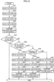
FIG. 12 is a flowchart showing details of a cell suction operation by the head. -
FIG. 13 is a diagram showing a pattern for confirming success or failure of cell suction. -
FIG. 14 is a perspective view showing one example of a cell transfer line assembled in the cell transfer apparatus. - An embodiment of the present invention will be described in detail below with reference to the drawings. The cell transfer apparatus according to the present invention can suction and transfer various types of cells of biological origin. Examples of the cell of biological origin include single cells such as hematopoietic cells and dissociated cells, tissue fragments such as histoculture, cell aggregation clusters such as spheroids and organoids, individuals such as zebrafish, nematodes, and fertilized eggs, 2D or 3D cell colony, and the like.
-
FIG. 1 is a diagram schematically showing the overall configuration of the cell transfer apparatus S. Here, the cell transfer apparatus S that transfers cells C between two containers is illustrated. The cell transfer apparatus S includes a translucent base BP having a horizontal placement surface, acamera unit 5 placed below the base BP, and ahead unit 6 placed above the base BP. Afirst container 41, which serves as the source of transfer of the cells C, is placed at a first placement position P1 of the base BP. Asecond container 42, which serves as the destination of transfer of the cells C, is placed at a second placement position P2 of the base BP. - The
first container 41 includes adish 43 that holds (arranges) the cells C in a scattered manner. Thesecond container 42 includesnumerous wells 45 that can accommodate the cells C. Thecamera unit 5 and thehead unit 6 are movable at least in the X direction. Thehead unit 6 includes a plurality ofheads 61 to each of which asuction tip 1 that suctions and discharges the cells C is attached. Theheads 61 are movable in the Z direction. - Generally speaking, the cell transfer apparatus S transfers the cells C from the
first container 41 at the first placement position P1 to thesecond container 42 at the second placement position P2. First, the cell transfer apparatus S sorts target cells C to be transferred from among numerous cells scattered on thedish 43 of thefirst container 41, and suctions and holds the target cells C with thesuction tip 1. Thesuction tip 1 that holds the cells C moves to thesecond container 42 together with thehead unit 6, and the cells C are discharged into thewell 45 of thesecond container 42. As will be described in detail later, during the suction in thefirst container 41, the set quantity of the target cells C that is set to two or more in advance is suctioned by thesuction tip 1, and the cells C are discharged into one well 45 (same location) of thesecond container 42. Each part of the cell transfer apparatus S will be described below. - The base BP is a rectangular flat plate having predetermined rigidity, and part or all of which includes a translucent material. The preferred base BP is a glass plate. The base BP includes a translucent material such as a glass plate, thereby allowing the
camera unit 5 placed below the base BP to capture images of the first andsecond containers - The
first container 41 stores a culture medium L, and holds thedish 43 for sorting cells in a state of being immersed in the culture medium L. Thedish 43 hasmultiple accommodation sections 44 that can accommodate the cells C on the upper side. Theaccommodation sections 44 each include a recess that can accommodate the cells C and are arranged in a matrix. Note thatFIGS. 8A and 8B show the upper view of thedish 43. The culture medium L is not particularly limited as long as the culture medium does not deteriorate the properties of the cells C, and can be appropriately selected depending on the type of cells C. - The
first container 41 includes a rectangularupper opening 11H on the upper surface side. Theupper opening 11H is an opening for injecting the cells C and picking up the sorted cells C. The injection of the cells C is a step of discharging a cell suspension containing a large amount of cells C from a dispenser tip (not shown). The pickup of the cells C is performed by thesuction tip 1 described above. Thedish 43 is placed below theupper opening 11H. Thefirst container 41 and thedish 43 are produced using a translucent resin material or glass. This is to allow thecamera unit 5 placed below thefirst container 41 to observe the cells C carried in thedish 43. - The
second container 42 is, for example, a microplate having multiple wells 45 (accommodation portions). Thewells 45 are each a bottomed hole opened on an upper surface of thesecond container 42. In onewell 45, a necessary number of cells C is accommodated together with the culture medium L. Thesecond container 42 is also produced using a translucent resin material or glass for allowing thecamera unit 5 to capture images. When discharging the cells C, a distal end t of the suction tip 12 enters the well 45. Each well 45 has an opening diameter that allows the distal end t to enter with room to spare. - The camera unit 5 (part of cell recognition unit) captures images of the cells C held in the
first container 41 or thesecond container 42 from the undersides. Thecamera unit 5 includes alens unit 51 and acamera body 52. Thelens unit 51 is an object lens used in an optical microscope, and includes a lens group that forms a light image with a predetermined magnification and a lens barrel that accommodates the lens group. Thecamera body 52 includes an image capturing element such as a CCD image sensor. Thelens unit 51 forms a light image of an image capturing target on a light receiving surface of the image capturing element. Thecamera unit 5 is movable horizontally along aguide rail 5G extending in the X direction. Thecamera unit 5 may also be movable in the Y direction orthogonal to the paper surface inFIG. 1 by a movement mechanism (not shown). - The
head unit 6 is a unit that performs the operation of picking the cells C from thefirst container 41 for transfer to thesecond container 42, and includes ahead group 6H having a plurality of theheads 61 and ahead body 62 to which thehead group 6H is assembled. Thesuction tip 1 that can suction and discharge the cells C is attached to the distal end of eachhead 61. Eachhead 61 includes a generating mechanism that generates suction force and discharge force at the distal end t of thesuction tip 1. Thehead body 62 holds theheads 61 to allow up-and-down movement in the +Z and -Z directions. Thehead unit 6 moves in the X direction where thefirst container 41 and thesecond container 42 are arranged along aguide rail 6G (movement mechanism). Actually, thehead unit 6 is also movable in the Y direction orthogonal to the paper surface inFIG. 1 by a movement mechanism (not shown). In this way, thehead unit 6 functions as a movement mechanism that causes thesuction tip 1 to perform horizontal movement in the XY direction and to perform up-and-down movement in the Z direction. - Subsequently, the structure of the
suction tip 1 attached to thehead 61 will be described.FIG. 2 is a cross-sectional view of thesuction tip 1.FIG. 3A is a cross-sectional view of asyringe 2,FIG. 3B is a cross-sectional view of aplunger 3, andFIG. 3C is an exploded perspective view of thesuction tip 1. Thesuction tip 1 includes thesyringe 2 with atubular passage 2P that serves as a suction path for the cells C, and theplunger 3 that is slidably accommodated inside thetubular passage 2P. - The
syringe 2 includes a syringeproximal end 21 having a large diameter cylindrical shape, asyringe body 22 having a small diameter long cylindrical shape, and ataper cylinder part 23 that connects theproximal end 21 and thebody 22. Thetubular passage 2P is formed in thesyringe body 22. At the distal end t located at one end of thesyringe body 22, a distal end opening 24 that serves as a suction port or discharge port for the cells C is provided. One end of thetubular passage 2P is connected to thedistal end opening 24. The syringeproximal end 21 is connected to the other end of thesyringe body 22 via thetaper cylinder part 23. - The
plunger 3 is a member that is inserted into thetubular passage 2P of thesyringe 2 and generates negative pressure for cell suction or positive pressure for cell discharge in the distal end opening 24 by moving back and forth inside thetubular passage 2P. Theplunger 3 includes a plungerproximal end 31 having a cylindrical shape, a needle-shapedplunger body 32, a dome-shapedpart 33 connecting theproximal end 31 and thebody 32, and a plungerdistal end 34 that is a protruding end of theplunger body 32. - The syringe
proximal end 21 includes a cylindricalhollow part 2H. The outer diameter of the plungerproximal end 31 is set to be smaller than the inner diameter of thehollow part 2H by a predetermined length. The outer diameter of theplunger body 32 is set to be slightly smaller than the inner diameter of thetubular passage 2P. The shape of the inner circumferential surface of thetaper cylinder part 23 matches the curved surface shape of the outer circumferential surface of the dome-shapedpart 33. Theplunger 3 is assembled with respect to thesyringe 2 in a mode in which the plungerproximal end 31 is accommodated in thehollow part 2H, and theplunger body 32 is inserted into thetubular passage 2P of thesyringe body 22. -
FIG. 3C shows the state where theplunger 3 is pulled out from thesyringe 2, butFIG. 2 shows the state where theplunger body 32 is inserted deepest into thesyringe body 22, that is, the state where theplunger 3 has descended the most. In this state, the dome-shapedpart 33 is completely accommodated in the cavity of thetaper cylinder part 23. The length of theplunger body 32 is slightly longer than thesyringe body 22, and in the state shown inFIG. 2 , the plungerdistal end 34 protrudes from thedistal end opening 24. In addition, there is a gap between the inner circumferential surface of the syringeproximal end 21 and the outer circumferential surface of the plungerproximal end 31. - The
plunger 3 can move upward with respect to thesyringe 2 from the state shown inFIG. 2 . When theplunger 3 moves upward by a predetermined length, the plungerdistal end 34 will be submerged inside thetubular passage 2P. At this time, suction force is generated in thedistal end opening 24, and the fluid around thedistal end opening 24, the culture medium L including the cells C in the present embodiment can be suctioned into thetubular passage 2P. After this suction, when theplunger 3 moves downward, the fluid suctioned into thetubular passage 2P can be discharged from thedistal end opening 24. - The
suction tip 1 is attached to the distal end of thehead 61 shown inFIG. 2 . Thehead 61 includes a firstcylindrical rod 611, a secondcylindrical rod 612 placed outside of the firstcylindrical rod 611, and a plunger rod 613 (generating mechanism/moving member) placed in the hollow part of the firstcylindrical rod 611. - While the second
cylindrical rod 612 is a fixed rod, theplunger rod 613 and the firstcylindrical rod 611 each move back and forth independently. The plungerproximal end 31 includes a mountinghole 3H, a cylindrical hollow space. The lower end of theplunger rod 613 is press-fitted into the mountinghole 3H. The upper end surface of the plungerproximal end 31 faces the lower end surface of the firstcylindrical rod 611. The lower end of the fixed secondcylindrical rod 612 is press-fitted into thehollow part 2H of the syringeproximal end 21. By the up-and-down movement of theplunger rod 613, theplunger 3 moves up and down, generating suction force or discharge force in the distal end opening 24 as described above. The firstcylindrical rod 611 is lowered when removing thesuction tip 1 from thehead 61. -
FIG. 4 is a block diagram showing the electric configuration of the cell transfer apparatus S. The cell transfer apparatus S includes acontrol unit 7 that controls the movement operation of thehead unit 6, the suction and discharge operation of the cells C by thesuction tip 1, the movement and image capturing operation of thecamera unit 5, and the like. In addition, the cell transfer apparatus S includes a cameraaxis driving unit 53 as a mechanism for causing thecamera unit 5 to horizontally move, anX-axis motor 63 and Y-axis motor 64 as mechanisms for horizontally moving thehead unit 6, a Z-axis motor 65 as a mechanism for raising and lowering thehead 61, and aplunger motor 66 as a mechanism for performing suction and discharge operations of the cells C, and further includes adisplay unit 54 and aninput unit 55. - The camera
axis driving unit 53 includes a driving motor for causing thecamera unit 5 to horizontally move along theguide rail 5G. TheX-axis motor 63 and the Y-axis motor 64 are driving sources for the movement mechanism that causes thehead unit 6 to move horizontally along theguide rail 6G. The preferred mode of the movement mechanism includes ball screws and nut members for the X axis and Y axis, and theX-axis motor 63 and the Y-axis motor 64 each rotate the ball screw forward or backward. - The Z-
axis motor 65 and theplunger motor 66 are built into thehead body 62. The Z-axis motor 65 causes thehead 61 to move up and down between the lowered position where thehead 61 extends downward from thehead body 62 and the raised position where most of thehead 61 is accommodated in thehead body 62. Theplunger motor 66 generates suction force and discharge force in the distal end opening 24 of thesuction tip 1 by raising and lowering theplunger rod 613 placed in the head 61 (FIG. 2 ). - The
display unit 54 includes a liquid crystal display or the like, and displays images captured by thecamera unit 5 and images that undergo image processing or the like by thecontrol unit 7. - The
input unit 55 includes a keyboard, touch panel, a communication unit for data communication with other communication devices, or the like, and receives input of operation information and various data from a user. In the present embodiment, theinput unit 55 receives input of the set quantity of the cells C to be discharged into one well 45 of the destinationsecond container 42 from the user. In other words, the input of the set quantity of the target cells C to be suctioned by onesuction tip 1 in thefirst container 41 is received from the user. - The
control unit 7 includes a processor or the like that performs various arithmetic processes, and includes an axis control unit 71 (part of the movement mechanism), asuction control unit 72, an image capturingcontrol unit 73, animage memory 74, an image processing unit 75 (part of the cell recognition unit), a sortingunit 76, adetermination unit 77, and astorage unit 78. - The
axis control unit 71 controls the operation of theX-axis motor 63 and the Y-axis motor 64 to cause thehead unit 6 to move to a predetermined horizontal target position. The movement of thehead 61 to which thesuction tip 1 is attached between thefirst container 41 and thesecond container 42, positioning perpendicularly above theaccommodation sections 44 of thedish 43, positioning perpendicularly above the well 45 of thesecond container 42 where discharge is performed, and the like are implemented by controlling theX-axis motor 63 and the Y-axis motor 64 by theaxis control unit 71. - The
suction control unit 72 controls the operation of the Z-axis motor 65 and theplunger motor 66 to perform the suction and discharge operation of the cells C by thesuction tip 1. Thesuction control unit 72 controls the operation of the Z-axis motor 65 to raise and lower thehead 61 to be controlled toward a predetermined target position. Thesuction control unit 72 controls the operation of theplunger motor 66 equipped on thehead 61 to be controlled to generate suction force or discharge force in the distal end opening 24 of thesuction tip 1 at a predetermined timing. - In the present embodiment, the
suction control unit 72 performs an operation of gradually suctioning the set quantity of the target cells C that is set to two or more in advance from among the cells C scattered on thedish 43 of thefirst container 41 into onesuction tip 1. The set quantity is a quantity received in theinput unit 55 from the user. Furthermore, after theaxis control unit 71 cause thehead 61 to move to thesecond container 42, thesuction control unit 72 performs an operation of discharging the set quantity of the target cells C suctioned by thesuction tip 1 into the same location in thesecond container 42, that is, onewell 45. Such control will be described using diagrams later with reference toFIGS. 5 to 7 . - The image capturing
control unit 73 controls the cameraaxis driving unit 53 to perform the operation of causing thecamera unit 5 to move along theguide rail 5G. In addition, the image capturingcontrol unit 73 controls the image capturing operation of thefirst container 41 or thesecond container 42 by thecamera unit 5. - The
image memory 74 is a storage area included in the microcomputer, an external storage, or the like. Image data acquired by thecamera unit 5 is temporarily stored in theimage memory 74. - The
image processing unit 75 performs image processing on image data captured by thecamera unit 5 and stored in theimage memory 74. Theimage processing unit 75 performs processing to recognize the position on the image of the cells C on thedish 43 based on the image of thedish 43 of thefirst container 41 after the cells C are dispensed. In addition, theimage processing unit 75 performs processing to recognize the distribution of the cells C, to recognize the size, shape, color tone, and the like of the recognized cells C, and the like by using the image processing technology. Theaxis control unit 71 and thesuction control unit 72 control the movement of thehead 61 and the suction and discharge of thesuction tip 1 based on the position recognition of the cells C, and perform the transfer operation of the cells C. - The sorting
unit 76 performs processing to sort the target cells C to be transferred to thesecond container 42 from a group of the cells C scattered in thefirst container 41 based on sorting criteria determined in advance. The sortingunit 76 derives the quality evaluation value of the cells C scattered on thedish 43 of thefirst container 41 based on the image captured by thecamera unit 5. Specifically, based on image processing results by theimage processing unit 75, for example, the feature amounts of the cell C such as the area or estimated volume of the cell C, the color or pattern of the cell C, and the light intensity when the cell C is fluorescent are extracted. In addition, the number of cells C accommodated in oneaccommodation section 44 is also detected as one of the feature amounts. This is because when multiple cells C are accommodated in theaccommodation section 44, it is difficult to control the number of cells C suctioned to thesuction tip 1, the cells C overlap, making accurate evaluation difficult, and other reasons. - Thereafter, the sorting
unit 76 identifies the cell with the evaluation value exceeding a predetermined threshold as the target cell C. That is, the extracted feature amount of each cell C is compared with a selection criteria parameter that is determined in advance as the range of cells C to be selected, and the target cell C is identified by evaluating whether the cell falls within the range of the selection criteria parameter. Through the processing by the sortingunit 76, only the cell C that is evaluated as having superior quality among the cells C accommodated in thefirst container 41 can be transferred to thesecond container 42 as the target cell C. - Based on the image of the
first container 41 after thesuction tip 1 performs the cell suction operation, or the image of thesecond container 42 after thesuction tip 1 performs the cell suction operation, thedetermination unit 77 determines whether the suction or discharge of the set quantity of the target cells C is achieved. This determination pattern will be described in detail later with reference toFIG. 13 . - The
storage unit 78 stores various setting values and data in the cell transfer apparatus S. In addition, thestorage unit 78 also stores the selection criteria parameter of the cell C to be transferred. The criteria for determining whether the cell C is good or bad may differ depending on the size and type, and, for example, it is preferable to have sorting criteria obtained from results of machine learning for each size and type. The sortingunit 76 reads the sorting criteria stored in thestorage unit 78 during the sorting process. - Subsequently, the cell transfer operation by the cell transfer apparatus S will be described with reference to
FIGS. 5 to 7 . The cell transfer operation includes the following steps (1) to (4) to be performed sequentially. - (1) A preliminary treatment step of causing the
suction tip 1 to hold a preliminary treatment liquid, - (2) A suction step of suctioning the set quantity of the target cells C into the
suction tip 1 in thefirst container 41, - (3) A movement step of moving the
suction tip 1 that has suctioned the cells C to thesecond container 42, and - (4) A discharge step of discharging all the cells C in the
suction tip 1 into the well 45 of thesecond container 42. -
FIGS. 5A to 5D andFIGS. 6A to 6D are diagrams showing the above-mentioned preliminary treatment step (1) and suction step (2).FIG. 5A shows thesuction tip 1 in a state of holding the preliminary treatment liquid LA in the space between thesyringe body 22 and theplunger body 32. In the preliminary treatment step (1), for example, the distal end t of thesyringe 2 is immersed in a container filled with the preliminary treatment liquid LA, and theplunger 3 moves back and forth about three times. This operation brings the preliminary treatment liquid LA into the space between thesyringe body 22 and theplunger body 32. A physiological saline solution or the like may be used as the preliminary treatment liquid LA, but it is preferable to use the culture medium L. -
FIGS. 5A and 5B are also diagrams showing the step of forming an air layer H inside thetubular passage 2P before performing the suction step (2). Thesuction control unit 72 places the distal end t of thesuction tip 1 in the air as shown inFIG. 5A , and drives theplunger motor 66 from the state where the plungerdistal end 34 protrudes from the distal end opening 24 of thesyringe 2 to raise theplunger 3 by a predetermined length. As a result, the air layer H is formed in thetubular passage 2P near thedistal end opening 24. -
FIGS. 5C to 6D show the execution status of the suction step (2) sequentially. In these figures, thefirst container 41 is shown in a simplified manner. In the culture medium L1 stored in thefirst container 41, the first cell C1, the second cell C2, and the third cell C3 selected as target cells to be transferred are scattered. Here, an example is shown where the set quantity of the target cells = 3. Based on the image of thefirst container 41 captured by thecamera unit 5 before cell suction, the position coordinates of each of the cells C1, C2, and C3 are determined. - The
suction control unit 72 causes onesuction tip 1 to suction the cells C1, C2, and C3 gradually. At this time, it is determined in what order to suction the cells C1, C2, and C3, that is, how to set the movement route for thehead 61. As the movement route, it is preferable to select a route that is the shortest movement distance by referring to the position coordinates of the cells C1, C2, and C3 in order to shorten the tact time. Here, the three target cells lined up horizontally are gradually suctioned in the order of the first cell C1, the second cell C2, and the third cell C3. -
FIG. 5C shows the state where the distal end opening 24 of thesuction tip 1 is aligned with the first cell C1. Theaxis control unit 71 causes thehead unit 6 to move such that thesuction tip 1 is positioned above thefirst container 41. At this time, thehead 61 moves such that the distal end opening 24 of thesuction tip 1 is positioned vertically above the first cell C1 by referring to the position coordinates of the first cell C1. Thesuction control unit 72 drives the Z-axis motor 65 to lower thehead 61 until the distal end t is immersed in the culture medium L1 in thefirst container 41, in more detail, until thedistal end opening 24 is positioned near immediately above the first cell C1 in the culture medium L1.FIG. 5C shows the state after the head is lowered. - Subsequently, the
suction control unit 72 drives theplunger motor 66 to raise theplunger 3 by a predetermined distance. As a result, thedistal end opening 24 is depressurized to generate suction force, causing a part of the culture medium L1 and the first cell C1 in thefirst container 41 to be suctioned from the distal end opening 24 into thetubular passage 2P. In thetubular passage 2P, the first cell C1 will float in the suctioned culture medium L1a.FIG. 5D shows the state after the first cell C1 is suctioned. - In the suction step (2), since the preliminary treatment liquid LA is held in advance in the space between the
syringe body 22 and theplunger body 32, the culture medium L1 will not rise rapidly in thetubular passage 2P due to capillary action or internal pressure. The air layer H functions as a sealing layer that separates the preliminary treatment liquid LA and the culture medium L1a containing the first cell C1 that is subsequently suctioned in thetubular passage 2P. Therefore, the suctioned first cell C1 does not transition into the preliminary treatment liquid LA. Therefore, it is possible to prevent the first cell C1 from being sandwiched between thesyringe body 22 and theplunger body 32. Furthermore, the presence of the air layer H makes it possible to prevent the preliminary treatment liquid LA from mixing with the culture medium L1 or prevent the preliminary treatment liquid LA from being discharged into thesecond container 42 in the subsequent discharge step (4). - Hereinafter, similar operations are repeated as many times as the set quantity of the target cells.
FIG. 6A shows the state where thehead 61 moves horizontally a small distance and the distal end opening 24 of thesuction tip 1 is aligned with the second cell C2. After that, thesuction control unit 72 drives the Z-axis motor 65 to lower thehead 61 until the distal end opening 24 of thesuction tip 1 is positioned near immediately above the second cell C2. Subsequently, thesuction control unit 72 drives theplunger motor 66 to raise theplunger 3 by a predetermined distance and generate suction force in the distal end opening 24 to suction the second cell C2 from thedistal end opening 24.FIG. 6B shows the state after the second cell C2 is suctioned. In this stage, the first cell C1 and the second cell C2 are held in thesuction tip 1 in a manner of being arranged up and down. -
FIG. 6C shows the state where thehead 61 moves further horizontally a small distance and the distal end opening 24 of thesuction tip 1 is aligned with the third cell C3. Thesuction control unit 72 drives the Z-axis motor 65 to lower thehead 61 until the distal end opening 24 of thesuction tip 1 is positioned near immediately above the third cell C3. Subsequently, thesuction control unit 72 drives theplunger motor 66 to raise theplunger 3 further by a predetermined distance and generate suction force in the distal end opening 24 to suction the third cell C3 from thedistal end opening 24.FIG. 6D shows the state after the third cell C2 is suctioned. In this example, the gradual suction of the target cells is completed here. In the state where the suction step (2) is completed, the first cell C1, the second cell C2, and the third cell C3 are held to be aligned in an up-and-down row inside thesuction tip 1. -
FIGS. 7A and 7B are diagrams showing the status of performing the movement step (3). After the completion of the suction step (2), theaxis control unit 71 causes thehead unit 6 to move such that thesuction tip 1 holding the cells C1, C2, and C3 is positioned above thesecond container 42. InFIG. 7B , thesecond container 42 is schematically depicted. The culture medium L2 is stored in thesecond container 42 as well. Actually, thehead unit 6 moves such that the distal end t of thesuction tip 1 is aligned with one well 45 among the plurality ofwells 45 included in thesecond container 42, the one well being the target for discharging. -
FIG. 7C is a diagram showing the status after the discharge step (3) is performed. Thesuction control unit 72 drives the Z-axis motor 65 to lower thehead 61 until the distal end opening 24 of thesuction tip 1 is immersed in the culture medium L2 in thesecond container 42. Subsequently, thesuction control unit 72 drives theplunger motor 66 to lower theplunger 3 by a predetermined distance. In more detail, theplunger 3 is lowered until the plungerdistal end 34 protrudes from thedistal end opening 24. As a result, as shown inFIG. 7C , the culture medium L1a and the cells C1, C2, and C3 held in thesuction tip 1 are discharged all at once into the culture medium L2 in thesecond container 42. -
FIGS. 8A and 8B are examples of images of thefirst container 41 having theaccommodation sections 44 before and after the cell suction. Thefirst container 41 includes thedish 43 having matrix-arrayedaccommodation sections 44, and numerous cells C are scattered in thedish 43. As shown inFIG. 8A , it is assumed that, among these cells C, the cells Ca, Cb, and Cc accommodated one by one in theaccommodation sections suction tip 1. - In this case, the
suction control unit 72 sets a movement route MR that passes through theaccommodation sections head 61 with the onesuction tip 1 attached. Then, while theaxis control unit 71 causes thehead 61 to intermittently move along the movement route MR, thesuction control unit 72 causes the onesuction tip 1 to gradually suction the cells Ca, Cb, and Cc. That is, until thesuction tip 1 finishes suctioning the set quantity of the target cells, thesuction control unit 72 causes thehead 61 to move across the plurality ofaccommodation sections suction tip 1 to perform the suction operation. - After the suction, as shown in
FIG. 8B , theaccommodation sections accommodation sections first container 41 after the cell suction and confirming the presence of the cells Ca, Cb, and Cc, it is possible to confirm whether the suction of the target cells by thesuction tip 1 is successful or not. - The
suction tip 1 that has suctioned the cells Ca, Cb, and Cc moves to thesecond container 42, discharging the cells Ca, Cb, and Cc into onewell 45.FIG. 8C is an example of an image of the one well 45 after the cell discharge. In the well 45 that accommodates the cells Ca, Cb and Cc, necessary operations such as introducing reagents are performed. -
FIGS. 9A and 9B are examples of images of afirst container 410 with a flat bottom having noaccommodation sections 44 before and after cell suction. Numerous cells C are scattered in thefirst container 410. As shown inFIG. 9A , it is assumed that, among the cells C, cells Cd, Ce, and Cf that exist one by one in regions PA1, PA2, and PA3 respectively are identified as target cells to be suctioned into onesuction tip 1. In this case as well, a movement route that passes through the regions PA1, PA2, and PA3 in the shortest distance is defined, and the cells Cd, Ce, and Cf are gradually suctioned into onesuction tip 1. Whether the suction is successful can be determined, for example, by image matching processing of the pre-suction image inFIG. 9A and the post-suction image inFIG. 9B. FIG. 9C is an example of an image after the cells Cd, Ce, and Cf are discharged into onewell 45. - The above is an operation focused on one
suction tip 1. Actually, the set quantity of the target cells C in thefirst container 41 is gradually suctioned into eachsuction tip 1 attached to themultiple heads 61 included in thehead unit 6. Then, the set quantity of the target cells C is discharged all at once from eachsuction tip 1 into each of the plurality ofwells 45 of thesecond container 42. That is, two or more target cells C held in eachsuction tip 1 are discharged into the well 45 assigned to eachsuction tip 1. According to the present embodiment, it is possible to transfer the set quantity of the target cells C from eachsuction tip 1 to each well 45 of thesecond container 42 in one movement operation of thehead unit 6 from thefirst container 41 to thesecond container 42. -
FIG. 10 is a flowchart showing an operation example of the cell transfer apparatus S. First, theinput unit 55 receives the set quantity of the target cells C to be suctioned by onesuction tip 1 from the user (step S1). The examples inFIG. 5 to FIG. 7 described above show the example where the set quantity = 3. It is preferable to make a selection from the range of about the set quantity = 2 to 5 because too large set quantity makes it difficult to suction the cells C into onesuction tip 1. - Next, the image capturing
control unit 73 controls thecamera unit 5 to capture an image of thefirst container 41 before cell suction. Theimage processing unit 75 performs image processing on data of the acquired pre-suction image to identify the position of the cells C scattered in the first container 41 (step S2). Subsequently, the sortingunit 76 derives an evaluation value about the quality of the cells C based on the pre-suction image, and identifies the cells with the evaluation value exceeding a predetermined threshold as target cells C to be transferred (step S3). - Next, under the control of the
axis control unit 71 and thesuction control unit 72, the cell transfer step including the above-described preliminary treatment step (1), suction step (2), movement step (3), and discharge step (4) is performed (step S4). After the suctioned target cells C are discharged into thesecond container 42, the image capturingcontrol unit 73 controls thecamera unit 5 to capture images of thefirst container 41 after the cell suction. Then, by comparing the pre-suction image acquired in step S2 with the post-suction image acquired in this step, thedetermination unit 77 confirms whether the suction of the target cells C is successful, that is, whether the transfer of the target cells is successful (step S5). - When all the set quantity of the target cells C is successfully suctioned (YES in step S6), the process ends. On the other hand, when the suction of the target cells C fails partially or completely (NO in step S6), returning to step S3, the cell transfer step for recovery is performed again.
-
FIG. 11 is a flowchart showing the operation of the cell transfer step of step S4. Here, an example is shown where thehead unit 6 includes threeheads 61, there are nine cells to be transferred, cells C1 to C9, and each of thesuction tips 1 attached to eachhead 61 suctions three cells (set quantity of target cells = 3). Note that the threeheads 61 described above are referred to as first head, second head, and third head in the flowchart ofFIG. 11 . - When the target cells C1 to C9 are selected in step S3 of
FIG. 10 , thesuction control unit 72 sets the movement route for the first head, second head, and third head on thefirst container 41 for suctioning these target cells (step S11). After that, while causing the first to third heads to move along the set movement route, thesuction control unit 72 sequentially suctions the target cells C1 to C9, three at a time per onesuction tip 1. - First, the
suction control unit 72 causes thesuction tip 1 attached to the first head to gradually suction the cells C1, C2, and C3 (steps S12, S13, S14). This series of suction operations involves the up-and-down and horizontal movement of the first head. Using the example of thedish 43 shown inFIG. 8A , the suction operation including the descent of the first head, suction of the cell Ca (C1) into thesuction tip 1, and the ascent of the first head is performed in theaccommodation section 44a to be approached first (step S12). Subsequently, the horizontal movement of the first head above theaccommodation section 44b to be approached second is performed, and the suction operation for the cell Cb (C2) is performed similarly (step S13). The horizontal movement of the first head and the suction operation on the cell Cc (C3) are performed on theaccommodation section 44c to be approached third as well (step S14). - Subsequently, the
suction control unit 72 causes thesuction tip 1 attached to the second head to gradually suction the cells C4, C5, and C6 (steps S15, S16, S17). Furthermore, thesuction control unit 72 causes thesuction tip 1 attached to the third head to gradually suction the cells C7, C8, and C9 (steps S18, S19, S20). The operation in these steps is the same as the suction operation for the first head (steps S12 to S14). - After completing the suction of the target cells C1 to C9 into the
suction tip 1 of each of the first to third heads, theaxis control unit 71 causes thehead unit 6 to move above the second container 42 (step S21). After that, thesuction control unit 72 discharges the target cells C1 to C9 from thesuction tip 1 of each of the first to third heads into the designated well 45 (step S22). In more detail, thesuction tip 1 of the first head is aligned with thefirst well 45 designated in advance, and the cells C1, C2, and C3 are discharged into thefirst well 45. Similarly, the cells C4, C5, and C6 are discharged from thesuction tip 1 of the second head to thesecond well 45 designated in advance, and the cells C7, C8, and C9 are discharged from thesuction tip 1 of the third head to thethird well 45 designated in advance. -
FIG. 12 is a flowchart showing details of the cell suction operation of the set quantity of the target cells C by thesuction tip 1 of onehead 61. The "head" in the flowchart ofFIG. 12 corresponds to one of the first head, second head, or third head in the flowchart ofFIG. 11 . Here again, the set quantity of the target cells C to be suctioned by onesuction tip 1 = 3. - The
suction control unit 72 causes thehead 61 to which thesuction tip 1 is attached to perform threesuction operations # 1, #2, and #3 in thefirst container 41 according to the set quantity = 3 (steps S31, S32, S33). Thesuction operations # 1, #2, and #3 here are the same as the suction operations described above in steps S12, S13, and S14. After that, thehead 61 moves to thesecond container 42, and thesuction control unit 72 discharges the target cells C suctioned in thesuction operations # 1, #2, and #3 into the well 45 determined in advance (step S34). - Subsequently, the
determination unit 77 performs processing to determine whether the suction of the target cells C is successful based on the comparison of images of thefirst container 41 before cell suction and images of thefirst container 41 after cell suction, or images of thesecond container 42 after cell discharge (step S36). When all of thesuction operations # 1, #2, and #3 are successful (YES in step S37), the process for thehead 61 this time (for example, first head) is completed, going to the process for the next head 61 (for example, second head). When all of thesuction operations # 1, #2, and #3 are not successful (NO in step S37), it is determined whether all of thesuction operations # 1, #2, and #3 have failed (step S38). - When all of the
suction operations # 1, #2, and #3 have failed (YES in step S38), thesuction control unit 72 makes a retry of the suction operation. That is, thesuction control unit 72 returns thehead 61 to the first container, and causes thesuction tip 1 attached to thehead 61 to perform threesuction operations # 1, #2, and #3 on the target cells C (steps S39, S40, S41). Subsequently, thehead 61 moves to thesecond container 42, and thesuction control unit 72 discharges the target cells C suctioned in the retrysuction operations # 1, #2, and #3 into the well 45 determined in advance (step S42). After that, thedetermination unit 77 makes a determination whether the suction is successful (step S43). When all of the retrysuction operations # 1, #2, and #3 are successful, the process ends. After that, when all of thesuction operations # 1, #2, and #3 are not successful, the retry may be made again, or the well 45 may be treated as failure without making the retry again. - When all of the
suction operations # 1, #2, and #3 have not failed (NO in step S38), the number of failures of the suction operations is checked (step S44). When the suction of two target cells C has failed, thesuction control unit 72 returns thehead 61 to the first container, and causes thesuction tip 1 attached to thehead 61 to perform two retrysuction operations # 1 and #2 on the target cells C (steps S45, S46). Subsequently, thehead 61 moves to thesecond container 42, and thesuction control unit 72 discharges the target cells C suctioned in the retrysuction operations # 1 and #2 to the well 45 determined in advance (step S47). After that, thedetermination unit 77 makes a determination whether the suction is successful (step S48). - In step S44, when it is determined that the suction of one target cell C has failed, the
suction control unit 72 returns thehead 61 to the first container, and causes thesuction tip 1 attached to thehead 61 to perform one retrysuction operation # 1 on the target cell C (step S49). Subsequently, thehead 61 moves to thesecond container 42, and thesuction control unit 72 discharges the target cell C suctioned in the retrysuction operation # 1 to the well 45 determined in advance (step S50). After that, thedetermination unit 77 makes a determination whether the suction is successful (step S51). - A variation of success or failure confirmation of cell suction by the
determination unit 77 performed in step S5 ofFIG. 10 , step S36 ofFIG. 12 , or the like will be described with reference toFIG. 13. FIG. 13 illustrates three patterns,patterns 1 to 3. To summarize the flowchart inFIG. 12 , thecontrol unit 7 causes thehead 61 to which thesuction tip 1 is attached to perform the suction operation of the target cells C in the first container 41 (step #1), and causes the target cells C to be discharged into the second container 42 (step #2). If the suction fails, the head returns to thefirst container 41 and performs the retry suction operation on the target cells C (step #3), and causes the target cells C to be discharged again into the second container 42 (step #4). - The timing for the
determination unit 77 to implement confirmation whether the cell suction is successful can be either between thesteps # 1 and #2 or afterstep # 2. The former timing when capturing images of thefirst container 41 is "pattern 1", the latter timing when capturing images of thefirst container 41 is "pattern 2", and the latter timing when capturing images of thesecond container 42 is "pattern 3". - In both
patterns suction tip 1 suctions the set quantity of the target cells C from thefirst container 41, thecamera unit 5 captures the post-suction image of thefirst container 41. Thedetermination unit 77 compares the post-suction image and the pre-suction image of thefirst container 41 acquired before the suction operation to determine whether the cell suction is successful. Inpattern 1, the confirmation whether success or failure is made beforestep # 2. According topattern 1, since success or failure becomes clear in the stage where thehead 61 exists near thefirst container 41, it is possible to perform the retry suction as is when the suction failure is detected. - Meanwhile, in
pattern 2, afterstep # 2, that is, after the set quantity of the target cells C is discharged to thesecond container 42, thecamera unit 5 captures the post-suction image of thefirst container 41, and the confirmation of success or failure is made. When the state where thesuction tip 1 has suctioned multiple cells C continues for a long time, this can cause problems such as these cells C may settle and form clumps in thesuction tip 1 or block thedistal end opening 24. According topattern 2, since the discharge of the suctioned target cells C into thesecond container 42 is prioritized, the occurrence of the above-described problems can be suppressed. - In
pattern 3, afterstep # 2, thecamera unit 5 captures the post-discharge image of thesecond container 42 to confirm whether the suction is successful. That is, thedetermination unit 77 compares the post-discharge image and the pre-suction image to determine whether the cell suction is successful. Inpattern 3, it is possible to confirm whether the discharge of the set quantity of the target cells C in thesecond container 42 is successful based on the post-discharge image. That is, the success or failure of the suction can be determined based on the result of discharge to thesecond container 42, enabling a more reliable determination. - Subsequently, with reference to
FIG. 14 , a more specificcell transfer apparatus 8 into which the schematic cell transfer apparatus S shown inFIG. 1 is incorporated is illustrated.FIG. 14 is a perspective view showing a configuration example of thecell transfer apparatus 8. Thecell transfer apparatus 8 includes acell transfer line 80, thecamera unit 5, thehead unit 6, and alighting unit 56. InFIG. 14 , the base that supports thecell transfer line 80 and the movement mechanism of each unit are omitted. - The
camera unit 5 and thehead unit 6 are as described inFIG. 1 . InFIG. 14 , thehead unit 6 including eightheads 61 to which thesuction tips 1 are attached is illustrated. Thehead unit 6 is movable in the X and Y directions, and can move on thecell transfer line 80 along a predetermined movement path. In addition, thehead 61 can rise and fall in the Z direction. - In the
cell transfer line 80, elements necessary for implementation of a series of cell transfer steps of picking up cells accommodated in the sourcefirst container 41 and transferring the cells to the destinationsecond container 42 are arranged in the X direction. In thecell transfer line 80, in order from the -X end, a dispensertip stock unit 82, acell stock unit 81, atip stock unit 84, a tipimage capturing unit 85, acell sorting unit 83, a blackcover placement unit 87, acell relocation unit 86, and atip disposal unit 88 are arranged in one line. - The
cell stock unit 81 is a section that stores cell culture solution in which a large amount of cells are dispersed, which is the source of dispensing. Thecell stock unit 81 includes atube 811 that is a cylindrical container for storing the cell culture solution containing cells. The dispensertip stock unit 82 is a section that stores a plurality ofdispenser tips 821. The dispensertip stock unit 82 is provided with aholder 822 that holds thedispenser tips 821 arranged in a matrix in an upright position. - The
cell sorting unit 83 is a section for sorting cells of a desired size from the cell culture solution containing cells of various sizes. Thecell sorting unit 83 includes thefirst container 41 that accommodates the cell culture solution, a holding table 831 that positions and holds thefirst container 41, and atable lid member 832 that covers an upper surface of thefirst container 41. Thefirst container 41 preferably includes thedish 43, in a similar manner to thefirst container 41 shown inFIG. 1 . An image of the cells carried in thefirst container 41 is captured by thecamera unit 5 under lighting by thelighting unit 56. This identifies the location of the cells to be suctioned. - The
tip stock unit 84 includes a holding box 841 that holds the large number ofsuction tips 1 described above arranged in a matrix. Thesuction tips 1 can be attached to and detached from theheads 61 of thehead unit 6. Thesuction tips 1 perform the function of suctioning the cells carried in thefirst container 41, conveying the cells as thehead unit 6 moves, and discharging the cells into thesecond container 42 in thecell relocation unit 86. Thesuction tips 1 are held in the holding box 841 in a state where attachment to theheads 61 that move in the Z direction can be easily made. In thetip stock unit 84, areservoir 842 that stores impregnating liquid that moistens the distal end opening 24 of thesuction tip 1 is also placed. - The tip
image capturing unit 85 is a pit that provides a location where an image of thesuction tip 1 attached to thehead 61 is captured. The image capturing is performed by thecamera unit 5. Based on the image of thesuction tip 1 and the focal position information during image capturing, the XYZ coordinate position of the distal end opening 24 of thesuction tip 1 is obtained. A correction value is derived from the difference between the coordinate position and a predetermined reference position, and is used as a correction value when controlling the movement of thehead 61. - The
cell relocation unit 86 is a section to which the cells suctioned by thesuction tip 1 from thefirst container 41 of thecell sorting unit 83 are transferred. Thecell relocation unit 86 includes thesecond container 42 and a holding table 861 that positions and holds thesecond container 42. Thesecond container 42 is a plate withnumerous wells 45 with an upper surface open as described above arranged in a matrix. The cells held by thesuction tip 1 are discharged into thewells 45. - The black
cover placement unit 87 is a section on which a firstblack cover 871 placed over thecell relocation unit 86 and a secondblack cover 872 placed over thecell sorting unit 83 are placed. The first and second black covers 871 and 872 are used when capturing images of cells carried in thefirst container 41 or thesecond container 42 in a state protected from light for cell fluorescence observation. Thetip disposal unit 88 is a section where thesuction tip 1 and thedispenser tip 821 are disposed of after use, after the cell suction and discharge operations are finished. - The
cell transfer apparatus 8 includes a controller (not shown) that controls the overall operation of thecell transfer apparatus 8. The controller broadly causes thecell transfer apparatus 8 to perform the dispensing operation by thedispenser tip 821 and the cell transfer operation using thesuction tip 1. The controller sequentially performs the followingcontrols 1 to 4 in the dispensing operation. - [Control 1] Move the
head unit 6 onto the dispensertip stock unit 82 and attach thedispenser tip 821 to the dispensing nozzle (not shown) mounted on thehead unit 6. - [Control 2] Move the
head unit 6 onto thecell stock unit 81 to suction the cell culture solution containing the cells stored in thetube 811 into thedispenser tip 821 by a predetermined dispensing amount. - [Control 3] Move the
head unit 6 onto thecell sorting unit 83 and discharge the cell culture solution in thedispenser tip 821 into thefirst container 41. - [Control 4] Move the
head unit 6 onto thetip disposal unit 88, remove the useddispenser tip 821 from the dispensing nozzle, and dispose of the dispenser tip in thedisposal unit 88. - The controller sequentially performs the following
controls 5 to 8 in the cell transfer operation. - [Control 5] Move the
head unit 6 onto thetip stock unit 84 and cause thesuction tip 1 to be fitted onto the distal end of thehead 61. - [Control 6] Move the
head unit 6 onto thecell sorting unit 83 and suction the cells accommodated in thefirst container 41 into thesuction tip 1. At this time, gradually suction the set quantity of the target cells that is set in advance to two or more into thesuction tip 1. - [Control 7] Move the
head unit 6 onto thecell relocation unit 86 and discharge the set quantity of the target cells in thesuction tip 1 into the same location of thesecond container 42, that is, to onewell 45. - [Control 8] Move the
head unit 6 onto thetip disposal unit 88, remove the usedsuction tip 1 from thehead 61, and dispose of the suction tip in thedisposal unit 88. - With the cell transfer apparatus described above, one
suction tip 1 suctions the set quantity of the target cells C together in thefirst container 41 to discharge the cells into one well 45 of thesecond container 41, thereby improving the efficiency of the transfer work of the cells C. In the conventional method, if multiple target cells C are required to be transferred to one well 45 of thesecond container 41, thehead 61 has to reciprocate multiple times between thefirst container 41 and thesecond container 42, and the cell transfer work takes a lot of time. In contrast, with the cell transfer apparatus of the present embodiment, after thesuction tip 1 sequentially suctions the set quantity of the target cells C in thefirst container 41, thehead 61 moves to thesecond container 42 and then discharges the cells into one well 45 all at once. Therefore, the number of reciprocations of thehead 61 between thefirst container 41 and thesecond container 42 can be reduced, and the time required for the cell transfer work can be shortened. - Note that the above-described specific embodiment mainly includes the invention having the following configurations.
- A cell transfer apparatus according to one aspect of the present invention is a cell transfer apparatus for transferring cells scattered in a first container to a second container, and includes: a head to which a suction tip configured to suction and discharge the cells is attached, the head including a generating mechanism that generates suction force and discharge force in a distal end opening of the suction tip; a movement mechanism that causes the head to perform horizontal movement and up-and-down movement; a cell recognition unit that includes a camera that captures an image of the first container in which the cells are scattered, the cell recognition unit performing position recognition on the cells based on the image; and a control unit that controls the head and the movement mechanism to perform a transfer operation of the cells based on a result of the position recognition, in which the control unit causes the suction tip to gradually suction a set quantity of target cells from among the cells scattered in the first container, the set quantity being set in advance to two or more, and after causing the head to move to the second container, the control unit causes the suction tip to discharge the set quantity of the target cells that is suctioned by the suction tip into a same location in the second container.
- With the cell transfer apparatus, the suction tip suctions the set quantity of the target cells together in the first container to discharge the cells into the same location of the second container, thereby improving the efficiency of the cell transfer work. In the conventional method, the suction tip suctions one target cell in the first container and moves to the second container, and discharges the one target cell into a specific location of the second container. In this method, if multiple target cells are required to be transferred to the specific location of the second container, the head has to reciprocate multiple times between the first container and the second container, and the cell transfer work takes a lot of time. In contrast, with the cell transfer apparatus described above, after the suction tip sequentially suctions the set quantity of the target cells in the first container, the head moves to the second container and then discharges the cells into the same location all at once. Therefore, the number of reciprocations of the head between the first container and the second container can be reduced, and the time required for the cell transfer work can be shortened.
- In the cell transfer apparatus, the suction tip may include a syringe having a tubular passage connected to the distal end opening, and a plunger slidably accommodated in the tubular passage to generate negative pressure in the distal end opening, the head may include a moving member that causes the plunger to move forward and backward as the generating mechanism, and the control unit may perform control to repeat, for the set quantity, an operation to cause the head to move to align the distal end opening of the suction tip with the target cells and cause the plunger to move to generate the suction force in the distal end opening to suction the target cells into the suction tip.
- According to this aspect, by simply controlling the forward and backward operation of the plunger, the sequential suction of the set quantity of the target cells into the suction tip and the discharge thereof can be performed.
- The cell transfer apparatus may further include a head unit including a plurality of the heads, the second plate may include a plurality of accommodation portions into which the target cells are discharged, and the control unit may cause each suction tip of the plurality of heads to suction the set quantity of the target cells, and discharge the set quantity of the target cells from the each suction tip into each of the plurality of accommodation portions.
- According to this aspect, it is possible to transfer the set quantity of the target cells from each suction tip to the plurality of accommodation portions in the second container in one movement operation of the head unit from the first container to the second container. Therefore, the time required for the cell transfer work can be further reduced.
- In the cell transfer apparatus, the control unit may be configured to derive an evaluation value of quality of the cells scattered in the first container based on the image captured by the camera, and to identify the cells with the evaluation value exceeding a predetermined threshold as the target cells.
- According to this aspect, only the cells that are evaluated as having superior quality among the cells accommodated in the first container can be transferred to the second container as the target cells.
- In the cell transfer apparatus, the control unit preferably determines a movement route for the head when the set quantity of the target cells is gradually suctioned into the suction tip based on the image captured by the camera.
- According to this aspect, it is possible to set an efficient movement route for the head by referring to the image of the first container. Therefore, the efficiency of the gradual suction operation of the target cells can be improved more than if the set quantity of the target cells is randomly suctioned into the suction tip.
- In the cell transfer apparatus, the control unit may cause the camera to capture a post-suction image of the first container after performing an operation of suctioning the set quantity of the target cells from the first container to the suction tip, and determine whether the suction tip suctions the set quantity of the target cells based on the post-suction image.
- According to this aspect, it is possible to confirm whether the suction of the set quantity of the target cells in the first container is successful based on the post-suction image. If it is determined that the suction has failed, it is possible to additionally transfer the missing target cells to a predetermined location in the second container.
- In the cell transfer apparatus, after discharging the set quantity of the target cells into the second container, the control unit preferably causes the camera to capture the post-suction image of the first container.
- When the state where the suction tip has suctioned multiple cells continues for a long time, this can cause problems such as these cells may settle and form clumps in the tip or block the distal end opening. According to the above aspect, since the discharge of the suctioned target cells into the second container is prioritized, the occurrence of the problems can be suppressed.
- In the cell transfer apparatus, the control unit may cause the camera to capture a post-discharge image of the second container after performing an operation of discharging the set quantity of the target cells from the suction tip to the second container, and determine whether the suction tip discharges the set quantity of the target cells based on the post-discharge image.
- According to this aspect, it is possible to confirm whether the discharge of the set quantity of the target cells in the second container is successful based on the post-discharge image. If it is determined that that discharge has failed, it is possible to additionally transfer the missing target cells to a predetermined location in the second container.
- In the cell transfer apparatus, the first container may have a plurality of accommodation sections each capable of accommodating cells, and the control unit may cause the head to move across the plurality of accommodation sections and cause the suction tip to perform a suction operation until the suction tip finishes suctioning the set quantity of the target cells.
- According to this aspect, it is possible to perform an operation of causing one suction tip to suction the target cells that exist in multiple accommodation sections and then discharging the target cells into the same location in the second container.
Claims (9)
- cell transfer apparatus for transferring cells scattered in a first container to a second container, the cell transfer apparatus comprising:a head to which a suction tip configured to suction and discharge the cells is attached, the head including a generating mechanism that generates suction force and discharge force in a distal end opening of the suction tip;a movement mechanism that causes the head to perform horizontal movement and up-and-down movement;a cell recognition unit that includes a camera that captures an image of the first container in which the cells are scattered, the cell recognition unit performing position recognition on the cells based on the image; anda control unit that controls the head and the movement mechanism to perform a transfer operation of the cells based on a result of the position recognition,wherein the control unit causes the suction tip to gradually suction a set quantity of target cells from among the cells scattered in the first container, the set quantity being set in advance to two or more, andafter causing the head to move to the second container, the control unit causes the suction tip to discharge the set quantity of the target cells that is suctioned by the suction tip into a same location in the second container.
- The cell transfer apparatus according to claim 1, whereinthe suction tip includes a syringe having a tubular passage connected to the distal end opening, and a plunger slidably accommodated in the tubular passage to generate negative pressure in the distal end opening,the head includes a moving member that causes the plunger to move forward and backward as the generating mechanism, andthe control unit repeats, for the set quantity, an operation to cause the head to move to align the distal end opening of the suction tip with the target cells and cause the plunger to move to generate the suction force in the distal end opening to suction the target cells into the suction tip.
- The cell transfer apparatus according to claim 1 or 2, further comprising a head unit including a plurality of the heads,wherein the second container includes a plurality of accommodation portions into which the target cells are discharged,the control unitcauses each suction tip of the plurality of heads to suction the set quantity of the target cells, anddischarges the set quantity of the target cells from the each suction tip into each of the plurality of accommodation portions.
- The cell transfer apparatus according to any one of claims 1 to 3, wherein the control unit derives an evaluation value of quality of the cells scattered in the first container based on the image captured by the camera, and identifies the cells with the evaluation value exceeding a predetermined threshold as the target cells.
- The cell transfer apparatus according to any one of claims 1 to 4, wherein the control unit determines a movement route for the head when the set quantity of the target cells is gradually suctioned into the suction tip based on the image captured by the camera.
- The cell transfer apparatus according to any one of claims 1 to 5, wherein
the control unitcauses the camera to capture a post-suction image of the first container after performing an operation of suctioning the set quantity of the target cells from the first container to the suction tip; anddetermines whether the suction tip suctions the set quantity of the target cells based on the post-suction image. - The cell transfer apparatus according to claim 6, wherein after discharging the set quantity of the target cells into the second container, the control unit causes the camera to capture the post-suction image of the first container.
- The cell transfer apparatus according to any one of claims 1 to 5, wherein
the control unitcauses the camera to capture a post-discharge image of the second container after performing an operation of discharging the set quantity of the target cells from the suction tip to the second container; anddetermines whether the suction tip discharges the set quantity of the target cells based on the post-discharge image. - The cell transfer apparatus according to any one of claims 1 to 8, whereinthe first container has a plurality of accommodation sections each capable of accommodating cells, andthe control unit causes the head to move across the plurality of accommodation sections and causes the suction tip to perform a suction operation until the suction tip finishes suctioning the set quantity of the target cells.
Applications Claiming Priority (1)
| Application Number | Priority Date | Filing Date | Title |
|---|---|---|---|
| PCT/JP2022/021920 WO2023233464A1 (en) | 2022-05-30 | 2022-05-30 | Cell transfer apparatus |
Publications (1)
| Publication Number | Publication Date |
|---|---|
| EP4512884A1 true EP4512884A1 (en) | 2025-02-26 |
Family
ID=89025922
Family Applications (1)
| Application Number | Title | Priority Date | Filing Date |
|---|---|---|---|
| EP22944051.6A Pending EP4512884A1 (en) | 2022-05-30 | 2022-05-30 | Cell transfer apparatus |
Country Status (4)
| Country | Link |
|---|---|
| EP (1) | EP4512884A1 (en) |
| JP (1) | JP7780009B2 (en) |
| CN (1) | CN119256073A (en) |
| WO (1) | WO2023233464A1 (en) |
Family Cites Families (5)
| Publication number | Priority date | Publication date | Assignee | Title |
|---|---|---|---|---|
| WO2014091525A1 (en) | 2012-12-13 | 2014-06-19 | ヤマハ発動機株式会社 | Suction tip, object observation device using said suction tip, and method for observing object |
| JP6450476B2 (en) | 2015-12-25 | 2019-01-09 | ヤマハ発動機株式会社 | Object moving method and apparatus |
| JP6841903B2 (en) * | 2017-04-20 | 2021-03-10 | ヤマハ発動機株式会社 | Cell transfer device and cell transfer method |
| WO2018193718A1 (en) * | 2017-04-20 | 2018-10-25 | ヤマハ発動機株式会社 | Cell handling device |
| WO2021019623A1 (en) * | 2019-07-26 | 2021-02-04 | 株式会社島津製作所 | Cell picking device |
-
2022
- 2022-05-30 JP JP2024524527A patent/JP7780009B2/en active Active
- 2022-05-30 WO PCT/JP2022/021920 patent/WO2023233464A1/en not_active Ceased
- 2022-05-30 CN CN202280096390.XA patent/CN119256073A/en active Pending
- 2022-05-30 EP EP22944051.6A patent/EP4512884A1/en active Pending
Also Published As
| Publication number | Publication date |
|---|---|
| CN119256073A (en) | 2025-01-03 |
| JPWO2023233464A1 (en) | 2023-12-07 |
| JP7780009B2 (en) | 2025-12-03 |
| WO2023233464A1 (en) | 2023-12-07 |
Similar Documents
| Publication | Publication Date | Title |
|---|---|---|
| CN107058097B (en) | Moving device for object | |
| US9977042B2 (en) | Object moving device | |
| US20200398265A1 (en) | Device for picking up biological subject | |
| CN107922907B (en) | Object moving method and object moving device | |
| CN110383042B (en) | camera system | |
| JP6883648B2 (en) | Cell handling device | |
| JP6450476B2 (en) | Object moving method and apparatus | |
| JP6387427B2 (en) | Object moving device | |
| JP7018078B2 (en) | Imaging system | |
| US20190381495A1 (en) | Tubular instrument and manipulation system | |
| JP7780009B2 (en) | cell transfer device | |
| JP7525657B2 (en) | Cell migration device | |
| JPWO2019150756A1 (en) | How to move biological objects and moving devices | |
| US20200339935A1 (en) | Pretreatment method for cell migration and cell migration device | |
| CN111699243B (en) | Camera system and biological object moving device | |
| WO2025037480A1 (en) | Cell movement device and method | |
| WO2018070153A1 (en) | Method for imaging cell |
Legal Events
| Date | Code | Title | Description |
|---|---|---|---|
| STAA | Information on the status of an ep patent application or granted ep patent |
Free format text: STATUS: THE INTERNATIONAL PUBLICATION HAS BEEN MADE |
|
| PUAI | Public reference made under article 153(3) epc to a published international application that has entered the european phase |
Free format text: ORIGINAL CODE: 0009012 |
|
| STAA | Information on the status of an ep patent application or granted ep patent |
Free format text: STATUS: REQUEST FOR EXAMINATION WAS MADE |
|
| 17P | Request for examination filed |
Effective date: 20241121 |
|
| AK | Designated contracting states |
Kind code of ref document: A1 Designated state(s): AL AT BE BG CH CY CZ DE DK EE ES FI FR GB GR HR HU IE IS IT LI LT LU LV MC MK MT NL NO PL PT RO RS SE SI SK SM TR |
|
| P01 | Opt-out of the competence of the unified patent court (upc) registered |
Free format text: CASE NUMBER: APP_12486/2025 Effective date: 20250313 |
|
| DAV | Request for validation of the european patent (deleted) | ||
| DAX | Request for extension of the european patent (deleted) |