EP4512770A1 - Positive active material, positive electrode plate, lithiumion battery, and electrical device - Google Patents
Positive active material, positive electrode plate, lithiumion battery, and electrical device Download PDFInfo
- Publication number
- EP4512770A1 EP4512770A1 EP24183657.6A EP24183657A EP4512770A1 EP 4512770 A1 EP4512770 A1 EP 4512770A1 EP 24183657 A EP24183657 A EP 24183657A EP 4512770 A1 EP4512770 A1 EP 4512770A1
- Authority
- EP
- European Patent Office
- Prior art keywords
- iron phosphate
- lithium iron
- phosphate particles
- active material
- lithium
- Prior art date
- Legal status (The legal status is an assumption and is not a legal conclusion. Google has not performed a legal analysis and makes no representation as to the accuracy of the status listed.)
- Pending
Links
Images


Classifications
-
- H—ELECTRICITY
- H01—ELECTRIC ELEMENTS
- H01M—PROCESSES OR MEANS, e.g. BATTERIES, FOR THE DIRECT CONVERSION OF CHEMICAL ENERGY INTO ELECTRICAL ENERGY
- H01M4/00—Electrodes
- H01M4/02—Electrodes composed of, or comprising, active material
- H01M4/36—Selection of substances as active materials, active masses, active liquids
- H01M4/58—Selection of substances as active materials, active masses, active liquids of inorganic compounds other than oxides or hydroxides, e.g. sulfides, selenides, tellurides, halogenides or LiCoFy; of polyanionic structures, e.g. phosphates, silicates or borates
- H01M4/5825—Oxygenated metallic salts or polyanionic structures, e.g. borates, phosphates, silicates, olivines
-
- C—CHEMISTRY; METALLURGY
- C01—INORGANIC CHEMISTRY
- C01B—NON-METALLIC ELEMENTS; COMPOUNDS THEREOF; METALLOIDS OR COMPOUNDS THEREOF NOT COVERED BY SUBCLASS C01C
- C01B25/00—Phosphorus; Compounds thereof
-
- C—CHEMISTRY; METALLURGY
- C01—INORGANIC CHEMISTRY
- C01B—NON-METALLIC ELEMENTS; COMPOUNDS THEREOF; METALLOIDS OR COMPOUNDS THEREOF NOT COVERED BY SUBCLASS C01C
- C01B25/00—Phosphorus; Compounds thereof
- C01B25/16—Oxyacids of phosphorus; Salts thereof
- C01B25/26—Phosphates
- C01B25/45—Phosphates containing plural metal, or metal and ammonium
-
- H—ELECTRICITY
- H01—ELECTRIC ELEMENTS
- H01M—PROCESSES OR MEANS, e.g. BATTERIES, FOR THE DIRECT CONVERSION OF CHEMICAL ENERGY INTO ELECTRICAL ENERGY
- H01M10/00—Secondary cells; Manufacture thereof
- H01M10/05—Accumulators with non-aqueous electrolyte
- H01M10/052—Li-accumulators
- H01M10/0525—Rocking-chair batteries, i.e. batteries with lithium insertion or intercalation in both electrodes; Lithium-ion batteries
-
- H—ELECTRICITY
- H01—ELECTRIC ELEMENTS
- H01M—PROCESSES OR MEANS, e.g. BATTERIES, FOR THE DIRECT CONVERSION OF CHEMICAL ENERGY INTO ELECTRICAL ENERGY
- H01M4/00—Electrodes
- H01M4/02—Electrodes composed of, or comprising, active material
- H01M4/13—Electrodes for accumulators with non-aqueous electrolyte, e.g. for lithium-accumulators; Processes of manufacture thereof
- H01M4/131—Electrodes based on mixed oxides or hydroxides, or on mixtures of oxides or hydroxides, e.g. LiCoOx
-
- H—ELECTRICITY
- H01—ELECTRIC ELEMENTS
- H01M—PROCESSES OR MEANS, e.g. BATTERIES, FOR THE DIRECT CONVERSION OF CHEMICAL ENERGY INTO ELECTRICAL ENERGY
- H01M4/00—Electrodes
- H01M4/02—Electrodes composed of, or comprising, active material
- H01M4/13—Electrodes for accumulators with non-aqueous electrolyte, e.g. for lithium-accumulators; Processes of manufacture thereof
- H01M4/136—Electrodes based on inorganic compounds other than oxides or hydroxides, e.g. sulfides, selenides, tellurides, halogenides or LiCoFy
-
- C—CHEMISTRY; METALLURGY
- C01—INORGANIC CHEMISTRY
- C01P—INDEXING SCHEME RELATING TO STRUCTURAL AND PHYSICAL ASPECTS OF SOLID INORGANIC COMPOUNDS
- C01P2002/00—Crystal-structural characteristics
- C01P2002/70—Crystal-structural characteristics defined by measured X-ray, neutron or electron diffraction data
- C01P2002/72—Crystal-structural characteristics defined by measured X-ray, neutron or electron diffraction data by d-values or two theta-values, e.g. as X-ray diagram
-
- C—CHEMISTRY; METALLURGY
- C01—INORGANIC CHEMISTRY
- C01P—INDEXING SCHEME RELATING TO STRUCTURAL AND PHYSICAL ASPECTS OF SOLID INORGANIC COMPOUNDS
- C01P2002/00—Crystal-structural characteristics
- C01P2002/70—Crystal-structural characteristics defined by measured X-ray, neutron or electron diffraction data
- C01P2002/76—Crystal-structural characteristics defined by measured X-ray, neutron or electron diffraction data by a space-group or by other symmetry indications
-
- C—CHEMISTRY; METALLURGY
- C01—INORGANIC CHEMISTRY
- C01P—INDEXING SCHEME RELATING TO STRUCTURAL AND PHYSICAL ASPECTS OF SOLID INORGANIC COMPOUNDS
- C01P2002/00—Crystal-structural characteristics
- C01P2002/70—Crystal-structural characteristics defined by measured X-ray, neutron or electron diffraction data
- C01P2002/77—Crystal-structural characteristics defined by measured X-ray, neutron or electron diffraction data by unit-cell parameters, atom positions or structure diagrams
-
- C—CHEMISTRY; METALLURGY
- C01—INORGANIC CHEMISTRY
- C01P—INDEXING SCHEME RELATING TO STRUCTURAL AND PHYSICAL ASPECTS OF SOLID INORGANIC COMPOUNDS
- C01P2004/00—Particle morphology
- C01P2004/51—Particles with a specific particle size distribution
-
- C—CHEMISTRY; METALLURGY
- C01—INORGANIC CHEMISTRY
- C01P—INDEXING SCHEME RELATING TO STRUCTURAL AND PHYSICAL ASPECTS OF SOLID INORGANIC COMPOUNDS
- C01P2006/00—Physical properties of inorganic compounds
- C01P2006/10—Solid density
-
- C—CHEMISTRY; METALLURGY
- C01—INORGANIC CHEMISTRY
- C01P—INDEXING SCHEME RELATING TO STRUCTURAL AND PHYSICAL ASPECTS OF SOLID INORGANIC COMPOUNDS
- C01P2006/00—Physical properties of inorganic compounds
- C01P2006/40—Electric properties
-
- H—ELECTRICITY
- H01—ELECTRIC ELEMENTS
- H01M—PROCESSES OR MEANS, e.g. BATTERIES, FOR THE DIRECT CONVERSION OF CHEMICAL ENERGY INTO ELECTRICAL ENERGY
- H01M4/00—Electrodes
- H01M4/02—Electrodes composed of, or comprising, active material
- H01M2004/021—Physical characteristics, e.g. porosity, surface area
-
- H—ELECTRICITY
- H01—ELECTRIC ELEMENTS
- H01M—PROCESSES OR MEANS, e.g. BATTERIES, FOR THE DIRECT CONVERSION OF CHEMICAL ENERGY INTO ELECTRICAL ENERGY
- H01M4/00—Electrodes
- H01M4/02—Electrodes composed of, or comprising, active material
- H01M2004/026—Electrodes composed of, or comprising, active material characterised by the polarity
- H01M2004/028—Positive electrodes
-
- Y—GENERAL TAGGING OF NEW TECHNOLOGICAL DEVELOPMENTS; GENERAL TAGGING OF CROSS-SECTIONAL TECHNOLOGIES SPANNING OVER SEVERAL SECTIONS OF THE IPC; TECHNICAL SUBJECTS COVERED BY FORMER USPC CROSS-REFERENCE ART COLLECTIONS [XRACs] AND DIGESTS
- Y02—TECHNOLOGIES OR APPLICATIONS FOR MITIGATION OR ADAPTATION AGAINST CLIMATE CHANGE
- Y02E—REDUCTION OF GREENHOUSE GAS [GHG] EMISSIONS, RELATED TO ENERGY GENERATION, TRANSMISSION OR DISTRIBUTION
- Y02E60/00—Enabling technologies; Technologies with a potential or indirect contribution to GHG emissions mitigation
- Y02E60/10—Energy storage using batteries
Definitions
- the present disclosure relates to the technical field of batteries, and more particularly, to a positive active material, a positive electrode plate, a lithium-ion battery, and an electrical device.
- an object of the present disclosure is to provide a positive active material having a relatively high compacted density.
- the positive active material can reduce impedance, improve conductivity, and sufficiently exert its own capacity.
- z / x ranges from 1.5 to 2.5.
- a volume percentage of the lithium iron phosphate particles having a particle size greater than 5 ⁇ m and smaller than 20 ⁇ m is z.
- x ranges from 11% to 30%, and z ranges from 5% to 40%.
- a volume percentage of the lithium iron phosphate particles having a particle size not smaller than 1 ⁇ m and not greater than 5 ⁇ m is y , y ranging from 40% to 80%.
- a volume of a unit cell of the lithium iron phosphate particles is V in units of ⁇ 3 , and V ranges from 291.1 to 294.6.
- a volume of a unit cell of the lithium iron phosphate particles is V in units of ⁇ 3 , and ( z / x )*( V /300) ranges from 0.49 to 2.74.
- the present disclosure provides a positive electrode plate including a positive current collector and a positive active substance layer coated on the positive current collector.
- the positive active substance layer includes the positive active material according to the first aspect of the present disclosure.
- the impedance can be reduced, the conductivity can be improved, and the capacity of the positive active substance layer can be sufficiently exerted.
- the present disclosure provides a lithium-ion battery including a housing and an electrode assembly disposed in the housing.
- the electrode assembly includes a negative electrode plate and a positive electrode plate.
- the positive electrode plate is the positive electrode plate according to the second aspect of the present disclosure.
- the impedance can be reduced, the conductivity can be improved, and the capacity of a positive electrode can be sufficiently exerted.
- the present disclosure provides an electrical device including the lithium-ion battery according to the third aspect of the present disclosure.
- the lithium-ion battery may be used as a power source for the electric device, the overall performance of the electric device can be improved due to the good overall performance of the lithium-ion battery.
- a positive active material according to embodiments of the present disclosure is described below.
- the positive active material includes lithium iron phosphate particles.
- a volume percentage of the lithium iron phosphate particles having a particle size smaller than 1 ⁇ m is x
- a volume percentage of the lithium iron phosphate particles having a particle size greater than 5 ⁇ m is z , where z / x ranges from 0.5 to 2.8.
- the volume percentage of the lithium iron phosphate particles having the particle size smaller than 1 ⁇ m means a ratio of a total volume of all lithium iron phosphate particles having the particle size smaller than 1 ⁇ m in the positive active material to a total volume of all lithium iron phosphate particles in the positive active material; and that the volume percentage of the lithium iron phosphate particles having the particle size greater than 5 ⁇ m refers to a ratio of a total volume of all lithium iron phosphate particles having the particle size greater than 5 ⁇ m in the positive active material to the total volume of all lithium iron phosphate particles in the positive active material.
- lithium iron phosphate particles of relatively small size When a value of z / x is smaller than 0.5, it indicates that there are many lithium iron phosphate particles of relatively small size.
- the excessive amount of lithium iron phosphate particles having the relatively small particle size may lead to a relatively low compacted density, relatively small spacing and gaps between lithium iron phosphate particles, relatively small space for absorbing electrolyte, and correspondingly, less electrolyte is absorbed.
- the electrolyte cannot infiltrate the lithium iron phosphate particles well, which may lead to a relatively great impedance for lithium ions diffusing between the lithium iron phosphate particles.
- lithium iron phosphate particles having the relatively small particle size charge migration in a single lithium iron phosphate particle may be easier and faster, and impedance of the charge migration is relatively small.
- more particles with the same mass may lead to a higher difficulty in dispersion under the same process conditions.
- a large number of lithium iron phosphate particles having the relatively small size are prone to cause problems of particle agglomeration.
- the electrolyte can better infiltrate the lithium iron phosphate particles, allowing the diffusion impedance for the lithium ions between the lithium iron phosphate particles to be relatively small.
- internal stress of a positive electrode material of the positive electrode plate is relatively long, and the large particles are easy to be broken, resulting in a loss of active substances, formation of dead lithium, and loss of capacity.
- the lithium iron phosphate particles having the relatively small particle size have a lower compacted density and a greater diffusion impedance for the lithium ions between the lithium iron phosphate particles.
- the lithium iron phosphate particles having the relatively small particle size are prone to agglomeration.
- the lithium iron phosphate particles having the relatively great particle size have a higher compacted density and a smaller diffusion impedance for the lithium ions between the lithium iron phosphate particles.
- the impedance of charge transfer is great.
- the lithium iron phosphate particles having the relatively great particle size have a problem that large particles are easy to be broken, which results in the loss of active substances.
- the lithium iron phosphate particles having the relatively great particle size and the lithium iron phosphate particles having the relatively small particle size are controlled within a certain range, and particularly, the ratio of the volume percentage of the lithium iron phosphate particles having a particle size greater than 5 ⁇ m to the volume percentage of the lithium iron phosphate particles having a particle size smaller than 1 ⁇ m is controlled within the range from 0.5 to 2.8.
- a ratio of relatively great particles to relatively small particles in the lithium iron phosphate particles can be controlled to be more appropriate, allowing particles to be stacked more reasonably, and allowing the positive active material as a whole to have a higher compacted density. Therefore, the impedance can be reduced, the conductivity can be improved, and the capacity of the positive active material can be sufficiently exerted.
- the lithium iron phosphate particles according to the embodiments of the present disclosure may be prepared by a high-temperature solid phase method or a high-temperature liquid phase method.
- the size and size distribution of the prepared lithium iron phosphate particles may be controlled by controlling reaction parameters (such as reaction time, reaction temperature, and the like).
- a lithium source, a divalent iron source, a phosphorus source, and a carbon source are mixed evenly at a certain ratio by mechanical ball milling or sanding to obtain a precursor; and then, the mixture reacts at a temperature ranging from 600°C to 1200°C for 2 hours to 10 hours in an inert atmosphere to obtain lithium iron phosphate particles.
- the ratio of the lithium source, the divalent iron source, the phosphorus source, and the carbon source may be (1.0 to 1.5): 1:1: (0.01 to 0.2), and the ratio refers to the molar ratio.
- a lithium source, a divalent iron source, and a phosphorus source are stirred in a mechanical stirred hydrothermal kettle at a certain ratio (with a solid content ranging from 20% to 60%) for 10 minutes to 120 minutes to obtain a precursor; and then, the mixture reacts at a temperature ranging from 120°C to 200°C for 2 hours to 12 hours in an inert atmosphere to obtain lithium iron phosphate particles.
- the ratio of the lithium source, the divalent iron source, the phosphorus source and the carbon source may be (2.3 to 3.5): 1: 1, and the ratio refers to the molar ratio.
- the lithium source may include at least one of lithium hydroxide (LiOH), lithium carbonate (Li 2 CO 3 ), lithium bicarbonate (LiHCO 3 ), lithium sulfate (Li 2 SO 4 ), lithium chloride (LiCl), lithium nitrate (LiNO 3 ), lithium oxalate (Li 2 C 2 O 4 ), and hydrates thereof.
- LiOH lithium hydroxide
- Li 2 CO 3 lithium carbonate
- LiHCO 3 lithium bicarbonate
- Li sulfate Li 2 SO 4
- LiCl lithium chloride
- LiNO 3 lithium nitrate
- Li 2 C 2 O 4 lithium oxalate
- the iron source may include at least one of ferrous oxide (FeO), ferroferric oxide (Fe 3 O 4 ), ferrous sulfate (FeSO 4 ), ferric sulfate (Fe 2 (SO 4 ) 3 ), ferric phosphate (FePO 4 ), ferrous chloride (FeCh), ferric chloride (FeCl 3 ), ferrous nitrate (Fe(NO 3 ) 2 ), ferric nitrate (Fe(NO 3 ) 3 ), and hydrates thereof.
- ferrous oxide FeO
- ferroferric oxide Fe 3 O 4
- FeSO 4 ferrous sulfate
- Fe 2 (SO 4 ) 3 ferric phosphate
- FePO 4 ferrous chloride
- FeCh ferric chloride
- FeCl 3 ferrous nitrate
- Fe(NO 3 ) 2 ferric nitrate
- Fe(NO 3 ) 3 ferric nitrate
- the phosphorus source may include phosphoric acid (H 3 PO 4 ), or a phosphorus-lithium compound such as lithium phosphate (Li 3 PO 4 ), lithium dihydrogen phosphate (LiH 2 PO 4 ), or lithium monohydrogen phosphate (Li 2 HPO 4 ), and the like.
- phosphoric acid H 3 PO 4
- a phosphorus-lithium compound such as lithium phosphate (Li 3 PO 4 ), lithium dihydrogen phosphate (LiH 2 PO 4 ), or lithium monohydrogen phosphate (Li 2 HPO 4 ), and the like.
- the carbon source may include glucose, polyethylene glycol, and the like.
- the positive active material by controlling the ratio of the volume percentage of the lithium iron phosphate particles having a particle size greater than 5 ⁇ m to the volume percentage of the lithium iron phosphate particles having a particle size smaller than 1 ⁇ m within the range from 0.5 to 2.8, the positive active material can have a higher compacted density, the impedance can be reduced, the conductivity can be improved, and the capacity of the positive active material can be sufficiently exerted.
- z / x ranges from 1.5 to 2.5.
- a value of z / x may be 1.5, 1.8, 2.0, 2.1, 2.2, 2.3, 2.4, 2.5, and the like.
- a volume percentage of the lithium iron phosphate particles having a particle size greater than 5 ⁇ m and smaller than 20 ⁇ m is z.
- the particle size of the lithium iron phosphate particles having the relatively great particle size in the range from 5 ⁇ m to 20 ⁇ m, the lithium iron phosphate particles having a relatively great size can have a more reasonable size, which avoids poor particle size consistency of the particles as a result of the particle size of the lithium iron phosphate particles having the relatively great particle size being too large.
- the overall performance of the positive active material including the lithium iron phosphate particles can be further improved.
- a volume of a unit cell of the lithium iron phosphate particles is V in units of ⁇ 3 , and V ranges from 291.1 to 294.6. If the volume V of the unit cell of the lithium iron phosphate particles is excessively small, the lithium ions are difficult to intercalate. If the volume V of the unit cell of the lithium iron phosphate particles is excessively large, deintercalation of the lithium ions may lead to an unstable unit cell skeleton, thereby leading to structural collapse and further leading to a loss of active substances and capacity.
- a volume of a unit cell of the lithium iron phosphate particles is V in units of ⁇ 3 , and ( z / x )*( V /300) ranges from 0.49 to 2.74.
- the volume V of the unit cell of the lithium iron phosphate particles and the above-mentioned z / x satisfy the relationship of 0.49 ⁇ ( z / x )*( V /300) ⁇ 2.74, the particle size distribution of the lithium iron phosphate particles and the volume V of the unit cell of the lithium iron phosphate can be also taken into account. In this way, the particle size distribution of the lithium iron phosphate particles in the positive active material is reasonable, and the stable lattice cell can be formed. Therefore, the positive active material also has a relatively high compacted density, conductivity and gram capacity, and an excellent structural stability, thereby improving the electrochemical performance of the positive active material.
- the positive electrode plate according to the embodiments in the second aspect of the present disclosure includes a positive current collector and a positive active substance layer coated on the positive current collector.
- the positive active substance layer includes the positive active material according to the embodiments in the first aspect of the present disclosure.
- the positive electrode plate since the positive electrode plate includes the above-mentioned positive active material, the impedance can be reduced, and the conductivity is increased, thereby promoting the positive active substance layer to sufficiently exert the capacity thereof.
- the lithium-ion battery according to the embodiments in the third aspect of the present disclosure includes a housing and an electrode assembly.
- the electrode assembly is disposed in the housing.
- the electrode assembly includes a negative electrode plate, a positive electrode plate, and a separator disposed between the positive electrode plate and the negative electrode plate.
- the positive electrode plate is the positive electrode plate according to the embodiments in the second aspect of the present disclosure.
- the impedance can be reduced, and the conductivity is increased, thereby promoting the positive active substance layer to sufficiently exert the capacity thereof.
- the electrical device includes the lithium-ion battery according to the embodiments in the third aspect of the present disclosure.
- the electric device may be an electric vehicle.
- the lithium-ion battery may be used as a power source for the electric device. Since the overall performance of the lithium-ion battery is good, the overall performance of the electric device can be improved.
- the positive active material according to the embodiments of the present disclosure is further described below in combination with examples and comparative examples.
- the lithium iron phosphate particles in the positive active material required for each example and comparative example were prepared.
- the lithium iron phosphate particles in each example and comparative example were prepared by the high-temperature solid phase method.
- Comparative Example 1 lithium carbonate (Li 2 CO 3 ), iron phosphate (FePO 4 ), and polyethylene glycol were mixed evenly at a ratio of 1.05:1:0.1 through mechanical ball milling or sanding, and then, the mixture reacted at 700°C in an inert atmosphere for 8 hours to obtain lithium iron phosphate (LFP) particles.
- LFP lithium iron phosphate
- a ratio of particle size distributions (0 to 1 ⁇ m) : (1 ⁇ m to 5 ⁇ m) : (5 ⁇ m to 20 ⁇ m) was 22: 78: 0, and V was 291.1 ⁇ 3 .
- Comparative Example 2 lithium carbonate (Li 2 CO 3 ), iron phosphate (FePO 4 ), and polyethylene glycol were mixed evenly at a ratio of 1.05:1:0.1 through mechanical ball milling or sanding, and then, the mixture reacted at 720°C in an inert atmosphere for 8 hours to obtain lithium iron phosphate (LFP) particles.
- LFP lithium iron phosphate
- a ratio of particle size distributions (0 to 1 ⁇ m) : (1 ⁇ m to 5 ⁇ m) : (5 ⁇ m to 20 ⁇ m) was 24: 70: 6, and V was 291.2 ⁇ 3 .
- Example 1 lithium carbonate (Li 2 CO 3 ), iron phosphate (FePO 4 ), and polyethylene glycol were mixed evenly at a ratio of 1.05:1:0.1 through mechanical ball milling or sanding, and then, the mixture reacted at 780°C in an inert atmosphere for 9 hours to obtain lithium iron phosphate (LFP) particles.
- LFP lithium iron phosphate
- Example 2 lithium carbonate (Li 2 CO 3 ), iron phosphate (FePO 4 ), and polyethylene glycol were mixed evenly at a ratio of 1.05: 1: 0.1 through mechanical ball milling or sanding, and then, the mixture reacted at 790°C in an inert atmosphere for 8.5 hours to obtain lithium iron phosphate (LFP) particles.
- LFP lithium iron phosphate
- Example 3 lithium carbonate (Li 2 CO 3 ), iron phosphate (FePO 4 ), and polyethylene glycol were mixed evenly at a ratio of 1.05: 1: 0.1 through mechanical ball milling or sanding, and then, the mixture reacted at 800°C in an inert atmosphere for 8 hours to obtain lithium iron phosphate (LFP) particles.
- LFP lithium iron phosphate
- Example 4 lithium carbonate (Li 2 CO 3 ), iron phosphate (FePO 4 ), and polyethylene glycol were mixed evenly at a ratio of 1.05: 1: 0.1 through mechanical ball milling or sanding, and then, the mixture reacted at 810°C in an inert atmosphere for 8 hours to obtain lithium iron phosphate (LFP) particles.
- LFP lithium iron phosphate
- Example 5 lithium carbonate (Li 2 CO 3 ), iron phosphate (FePO 4 ), and polyethylene glycol were mixed evenly at a ratio of 1.05: 1: 0.1 through mechanical ball milling or sanding, and then, the mixture reacted at 815°C in an inert atmosphere for 9.5 hours to obtain lithium iron phosphate (LFP) particles.
- LFP lithium iron phosphate
- Example 6 lithium carbonate (Li 2 CO 3 ), iron phosphate (FePO 4 ), and polyethylene glycol were mixed evenly at a ratio of 1.05: 1: 0.1 through mechanical ball milling or sanding, and then, the mixture reacted at 820°C in an inert atmosphere for 10 hours to obtain lithium iron phosphate (LFP) particles.
- LFP lithium iron phosphate
- a ratio of particle size distributions (0 to 1 ⁇ m): (1 ⁇ m to 5 ⁇ m): (5 ⁇ m to 20 ⁇ m) was 14: 55: 31, and V was 294.3 ⁇ 3 .
- Example 7 lithium carbonate (Li 2 CO 3 ), iron phosphate (FePO 4 ), and polyethylene glycol were mixed evenly at a ratio of 1.05: 1: 0.1 through mechanical ball milling or sanding, and then, the mixture reacted at 850°C in an inert atmosphere for 12 hours to obtain lithium iron phosphate (LFP) particles.
- LFP lithium iron phosphate
- a ratio of particle size distributions (0 to 1 ⁇ m): (1 ⁇ m to 5 ⁇ m): (5 ⁇ m to 20 ⁇ m) was 14: 51: 35, and V was 294.2 ⁇ 3 .
- Example 8 lithium carbonate (Li 2 CO 3 ), iron phosphate (FePO 4 ), and polyethylene glycol were mixed evenly at a ratio of 1.05: 1: 0.1 through mechanical ball milling or sanding, and then, the mixture reacted at 850°C in an inert atmosphere for 10 hours to obtain lithium iron phosphate (LFP) particles.
- LFP lithium iron phosphate
- a ratio of particle size distributions (0 to 1 ⁇ m): (1 ⁇ m to 5 ⁇ m): (5 ⁇ m to 20 ⁇ m) was 14: 47: 39, and V was 294.1 ⁇ 3 .
- Comparative Example 3 lithium carbonate (Li 2 CO 3 ), iron phosphate (FePO 4 ), and polyethylene glycol were mixed evenly at a ratio of 1.05: 1: 0.1 through mechanical ball milling or sanding, and then, the mixture reacted at 780°C in an inert atmosphere for 15 hours to obtain lithium iron phosphate (LFP) particles.
- LFP lithium iron phosphate
- a ratio of particle size distributions (0 to 1 ⁇ m): (1 ⁇ m to 5 ⁇ m): (5 ⁇ m to 20 ⁇ m) was 14: 44: 42, and V was 294.6 ⁇ 3 .
- Comparative Example 4 lithium carbonate (Li 2 CO 3 ), iron phosphate (FePO 4 ), and polyethylene glycol were mixed evenly at a ratio of 1.05: 1: 0.1 through mechanical ball milling or sanding, and then, the mixture reacted at 780°C in an inert atmosphere for 18 hours to obtain lithium iron phosphate (LFP) particles.
- LFP lithium iron phosphate
- a ratio of particle size distributions (0 to 1 ⁇ m): (1 ⁇ m to 5 ⁇ m): (5 ⁇ m to 20 ⁇ m) was 13: 44: 43, and V was 294.7 ⁇ 3 .
- the lithium iron phosphate particles prepared in the respective examples and comparative examples were subjected to scanning electron microscope detection, particle size distribution test, X-ray diffraction spectrum, compacted density test, and powder resistivity test, respectively.
- the scanning electron microscope (SEM) detection was mainly used to qualitatively analyze the particle size distribution of the lithium iron phosphate particles in the respective examples and comparative examples.
- the scanning electron microscope detection may also be used to detect the morphology of the lithium iron phosphate particles in the respective examples and comparative examples.
- the instrument for the scanning electron microscope was Zeiss sigma300, with magnifications of 1k, 5k, 1w, and 3w.
- the particle size distribution test was used to quantitatively analyze the particle size distribution of the lithium iron phosphate particles in the respective examples and comparative examples.
- the instrument was Master Size 3000, with a measurement range from 0.02 ⁇ m to 2000 ⁇ m and a detection angle ranging from 0 to 135°.
- the data of particle size distribution were obtained.
- the data of particle size distribution were imported into Origin (a software for drawing and data analysis) for graphing, where the horizontal coordinate is the particle size ( ⁇ m), and the vertical coordinate is the volume distribution (%), to obtain particle size distribution curves.
- Origin a software for drawing and data analysis
- the "Analysis"-"Integral" in origin was clicked. A range from 0 ⁇ m to the maximum particle size was selected to obtain integral area 1, which was the total volume of all lithium iron phosphate particles.
- a range smaller than 1 ⁇ m was selected to obtain integral area 2, which was the total volume of all lithium iron phosphate particles having a particle size smaller than 1 ⁇ m.
- a range greater than 5 ⁇ m was selected to obtain integral area 3, which was the total volume of all lithium iron phosphate particles having a particle size greater than 5 ⁇ m.
- a volume percentage x of the lithium iron phosphate particles having a particle size smaller than 1 ⁇ m integral area 2/integral area 1
- a volume percentage z of the lithium iron phosphate particles having a particle size greater than 5 ⁇ m integral area 3/integral area 1.
- the X-ray diffraction spectrum was used to detect and calculate the unit cell volume of the lithium iron phosphate particles in the respective examples and comparative examples.
- the instrument and parameters were PANalyticalX'Pert 3 , Cu target, 5° to 80°, and 5°/min.
- the compacted density test was used to measure the compacted density of the lithium iron phosphate particles in the respective examples and comparative examples under different pressures.
- the instrument was an electronic pressure tester (force test).
- the sample weight was 1 ⁇ 0.05g.
- the pressurized displacement control was 10 mm/min and pressure holding was performed for 30s.
- the pressure relief displacement control was 30 mm/min and pressure holding was performed for 10s.
- the test pressures were 1T, 2T, and 3T.
- the powder resistivity test was used to measure the powder resistivity of the lithium iron phosphate particles in the respective examples and comparative examples under different pressures.
- the instrument was IEST PRCD3100 (INITAL ENERGY SCIENCE&TECHNOLOGY Co., Ltd), 0 to 200 MPa.
- the lithium iron phosphate particles prepared in the respective examples and comparative examples were used as positive active materials.
- the positive active material lithium iron phosphate, a conductive agent (conductive carbon black, SP), and a binder (polyvinylidene fluoride (PVDF)) were dispersed in a solvent N-methylpyrrolidone (NMP) at a mass ratio of 85: 10: 5 and mixed evenly to obtain a positive electrode slurry.
- NMP solvent N-methylpyrrolidone
- the positive electrode slurry was coated on a positive current collector, i.e., an aluminum foil, and dried to obtain a positive active substance layer. Then, a positive electrode plate was obtained by stamping. Lithium metal was used as a negative electrode to prepare a button battery.
- the button battery was subjected to an electrochemical performance test.
- the electrochemical performance tests included EIS impedance and gram capacity, and the parameters obtained from the tests refer to the following Table 1. It should be noted that the compacted density and powder resistivity listed in the following Table 1 were all measured under a pressure of 30 MPa. [Table 1] No.
- Example 1 0 291.1 0.00 2.45 18.04 125.32 156.47 Comparative Example 2 0.2 291.2 0.19 2.45 18.06 124.88 156.57 Example 1 0.5 291.5 0.49 2.45 17.25 124.08 157.66 Example 2 0.8 291.8 0.78 2.45 17.08 123.26 157.35 Example 3 1 292.5 0.98 2.46 16.73 119.38 157.03 Example 4 1.5 293.2 1.47 2.47 14.36 118.36 157.66 Example 5 1.8 293.8 1.76 2.47 13.87 118.75 157.73 Example 6 2.2 294.3 2.16 2.48 12.17 117.64 158.07 Example 7 2.5 294.2 2.45 2.51 14.97 119.67 158.01 Example 8 2.8 294.1 2.74 2.50 16.
- Table 1 reveals that when the ratio of z / x is in the range from 0.5 to 2.8, the lithium iron phosphate particles have a higher compacted density, lower powder resistivity, lower EIS impedance, and a higher gram capacity, thereby reducing the internal resistance and improving the conductivity and capacity.
- the ratio of z / x is in the range from 1.8 to 2.5, the overall internal resistance is lower, the conductivity is better, and the capacity is higher.
- FIG. 1 The photographs of the lithium iron phosphate particles in Example 6 and Comparative Example 1 detected by scanning electron microscope (SEM) refer to FIG. 1 . It can be seen from FIG. 1 (in particular, it can be clearly seen at a magnification of 3w) that the particle size of the lithium iron phosphate particles in Example 6 is greater than that of the lithium iron phosphate particles in Comparative Example 1.
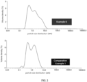
- Example 6 The specific particle size distribution of the lithium iron phosphate particles in Example 6 and Comparative Example 1 was shown in Table 2 and FIG. 2 below. [Table 2] No. Particle size distribution D10 D50 D90 D99 D100 Example 6 0.423 1.173 5.023 10.127 14.425 Comparative Example 1 0.379 1.002 2.815 4.991 6.707
- the lithium iron phosphate particles in Example 6 had a greater overall particle size, and large-sized particles took a greater proportion.
- the lithium iron phosphate particles having a particle size in a range from 0 to 1 ⁇ m accounted for 22%
- the lithium iron phosphate particles having a particle size in a range from 1 ⁇ m to 5 ⁇ m accounted for 78%
- the lithium iron phosphate particles having a particle size in a range from 5 ⁇ m to 20 ⁇ m accounted for 0% the lithium iron phosphate particles having a particle size in a range from 5 ⁇ m to 20 ⁇ m accounted for 0%.
- Example 6 the lithium iron phosphate particles having a particle size in a range from 0 to 1 ⁇ m accounted for 14%, the lithium iron phosphate particles having a particle size in a range from 1 ⁇ m to 5 ⁇ m accounted for 55%, and the lithium iron phosphate particles having a particle size in a range from 5 ⁇ m to 20 ⁇ m accounted for 31%.
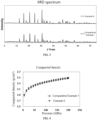
- the XRD data of the lithium iron phosphate particles in Example 6 and Comparative Example 1 were shown in Table 3 and FIG. 3 .
- the unit cell of the lithium iron phosphate particles in Comparative Example 1 was slightly shorter on a, b, and c axes, and had a smaller volume of the unit cell, which was 291.1 ⁇ 3 .
- the unit cell of the lithium iron phosphate particles in Example 6 was slightly longer on the a, b, and c axes, and the unit cell volume was 294.3 ⁇ 3 .
- Table 3 No.
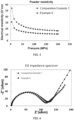
- FIG. 4 illustrates compacted density-pressure curves of the lithium iron phosphate particles in Example 6 and Comparative Example 1.
- the compacted density of the lithium iron phosphate particles in Example 6 is higher than the compacted density of the lithium iron phosphate particles in Comparative Example 1 at different pressures.
- FIG. 5 illustrates powder resistivity-pressure curves of the lithium iron phosphate particles in Example 6 and Comparative Example 1. Referring to FIG. 5 , at different pressures, the powder resistivity of the lithium iron phosphate particles in Example 6 is always significantly higher than the powder resistivity of the lithium iron phosphate particles in Comparative Example 1.
- FIG. 6 illustrates a comparison graph of EIS impedance spectrum of button batteries corresponding to the lithium iron phosphate particles in Example 6 and Comparative Example 1.
- the impedance of charge transfer of the button battery corresponding to the lithium iron phosphate particles in Example 6 is smaller than the impedance of charge transfer of the button battery corresponding to the lithium iron phosphate particles in Comparative Example 1, demonstrating that the battery corresponding to the lithium iron phosphate particles in Example 6 has a smaller charge and discharge polarization and thus the capacity can be more sufficiently exerted during the cycle.
Landscapes
- Chemical & Material Sciences (AREA)
- Engineering & Computer Science (AREA)
- Chemical Kinetics & Catalysis (AREA)
- Electrochemistry (AREA)
- General Chemical & Material Sciences (AREA)
- Materials Engineering (AREA)
- Inorganic Chemistry (AREA)
- Organic Chemistry (AREA)
- Manufacturing & Machinery (AREA)
- Crystallography & Structural Chemistry (AREA)
- Battery Electrode And Active Subsutance (AREA)
Abstract
Description
- The present disclosure relates to the technical field of batteries, and more particularly, to a positive active material, a positive electrode plate, a lithium-ion battery, and an electrical device.
- Lithium-ion batteries, as apparatuses for energy storage and conversion, have various advantages such as high energy density, high working voltage, high energy conversion efficiency, long cycle life, and no memory effect, compared with conventional nickel-metal hydride batteries and lead-acid batteries. A positive electrode material, as the most critical core component of the lithium-ion batteries, is an important factor for determining performances of the lithium-ion batteries in terms of cost, voltage, energy density, rate, cycle, safety, and the like. Among many positive electrode materials of the lithium-ion batteries, lithium iron phosphate (LiFePO4) has characteristics of low price, abundant raw materials, safety, environment friendliness, and good thermal stability.
- However, when lithium iron phosphate in the related art is used as a positive electrode material, there are still problems such as great internal resistance and poor conductivity, restricting a further improvement in the performances of the batteries employing lithium iron phosphate as the positive electrode material. Therefore, it is urgent to make further improvements.
- The present disclosure aims to at least solve one of the technical problems existing in the prior art. To this end, an object of the present disclosure is to provide a positive active material having a relatively high compacted density. The positive active material can reduce impedance, improve conductivity, and sufficiently exert its own capacity.
- In a first aspect, the present disclosure provides a positive active material. The positive active material includes lithium iron phosphate particles. A volume percentage of the lithium iron phosphate particles having a particle size smaller than 1 µm is x, and a volume percentage of the lithium iron phosphate particles having a particle size greater than 5 µm is z, where z/x ranges from 0.5 to 2.8.
- According to the positive active material in the embodiments of the present disclosure, by controlling a ratio of the percentage of the lithium iron phosphate particles having a particle size greater than 5 µm to the percentage of the lithium iron phosphate particles having a particle size smaller than 1 µm within a range from 0.5 to 2.8, the positive active material can have a relatively high compacted density. In this way, the impedance can be reduced, the conductivity can be improved, and the capacity of the positive active material can be sufficiently exerted.
- According to some embodiments of the present disclosure, z/x ranges from 1.5 to 2.5.
- According to some embodiments of the present disclosure, a volume percentage of the lithium iron phosphate particles having a particle size greater than 5 µm and smaller than 20 µm is z.
- According to some embodiments of the present disclosure, x ranges from 11% to 30%, and z ranges from 5% to 40%.
- According to some embodiments of the present disclosure, a volume percentage of the lithium iron phosphate particles having a particle size not smaller than 1 µm and not greater than 5 µm is y, y ranging from 40% to 80%.
- According to some embodiments of the present disclosure, a volume of a unit cell of the lithium iron phosphate particles is V in units of Å3, and V ranges from 291.1 to 294.6.
- According to some embodiments of the present disclosure, a volume of a unit cell of the lithium iron phosphate particles is V in units of Å3, and (z/x)*(V/300) ranges from 0.49 to 2.74.
- In a second aspect, the present disclosure provides a positive electrode plate including a positive current collector and a positive active substance layer coated on the positive current collector. The positive active substance layer includes the positive active material according to the first aspect of the present disclosure.
- For the positive electrode plate according to the embodiments of the present disclosure, by including the above-mentioned positive active material in the positive active substance layer, the impedance can be reduced, the conductivity can be improved, and the capacity of the positive active substance layer can be sufficiently exerted.
- In a third embodiment, the present disclosure provides a lithium-ion battery including a housing and an electrode assembly disposed in the housing. The electrode assembly includes a negative electrode plate and a positive electrode plate. The positive electrode plate is the positive electrode plate according to the second aspect of the present disclosure.
- For the lithium-ion battery according to the embodiments of the present disclosure, by providing the above-mentioned positive electrode plate as the positive electrode plate, the impedance can be reduced, the conductivity can be improved, and the capacity of a positive electrode can be sufficiently exerted.
- In a fourth aspect, the present disclosure provides an electrical device including the lithium-ion battery according to the third aspect of the present disclosure.
- For the electric device according to the embodiments of the present disclosure, by providing the above-mentioned lithium-ion battery, the lithium-ion battery may be used as a power source for the electric device, the overall performance of the electric device can be improved due to the good overall performance of the lithium-ion battery.
- Additional aspects and advantages of the present disclosure may be given in part in the following descriptions, become apparent in part from the following descriptions, or be learned from the practice of the embodiments of the present disclosure.
- The above-mentioned and/or additional aspects and advantages of the present disclosure may become apparent and more readily appreciated from the following descriptions made with reference to the accompanying drawings, in which:
-
FIG. 1 is a comparison of scanning electron microscope photographs of lithium iron phosphate particles in Example 6 and lithium iron phosphate particles in Comparative Example 1; -
FIG. 2 is a comparison of particle size distribution graphs of lithium iron phosphate particles in Example 6 and lithium iron phosphate particles in Comparative Example 1; -
FIG. 3 is a comparison of X-ray diffraction spectrums of lithium iron phosphate particles in Example 6 and lithium iron phosphate particles in Comparative Example 1; -
FIG. 4 is a comparison graph of compacted density-pressure curves of lithium iron phosphate particles in Example 6 and lithium iron phosphate particles in Comparative Example 1; -
FIG. 5 is a comparison graph of powder resistivity-pressure curves of lithium iron phosphate particles in Example 6 and lithium iron phosphate particles in Comparative Example 1; -
FIG. 6 is a comparison graph of EIS impedance spectrums of button cells corresponding to lithium iron phosphate particles in Example 6 and lithium iron phosphate particles in Comparative Example 1; and -
FIG. 7 is a comparison graph of gram capacity-voltage curves of button cells corresponding to lithium iron phosphate particles in Example 6 and lithium iron phosphate particles in Comparative Example 1. - Embodiments of the present disclosure may be described in detail below with reference to examples thereof as illustrated in the accompanying drawings, throughout which the same or similar elements, or elements having the same or similar functions, are denoted by same or similar reference numerals. The embodiments described below with reference to the drawings are illustrative only, and are intended to explain, rather than limiting, the present disclosure.
- A positive active material according to embodiments of the present disclosure is described below.
- According to an embodiment in a first aspect of the present disclosure, the positive active material includes lithium iron phosphate particles. A volume percentage of the lithium iron phosphate particles having a particle size smaller than 1 µm is x, and a volume percentage of the lithium iron phosphate particles having a particle size greater than 5 µm is z, where z/x ranges from 0.5 to 2.8.
- It should be noted that the volume percentage of the lithium iron phosphate particles having the particle size smaller than 1 µm means a ratio of a total volume of all lithium iron phosphate particles having the particle size smaller than 1 µm in the positive active material to a total volume of all lithium iron phosphate particles in the positive active material; and that the volume percentage of the lithium iron phosphate particles having the particle size greater than 5 µm refers to a ratio of a total volume of all lithium iron phosphate particles having the particle size greater than 5 µm in the positive active material to the total volume of all lithium iron phosphate particles in the positive active material.
- When a value of z/x is smaller than 0.5, it indicates that there are many lithium iron phosphate particles of relatively small size. The excessive amount of lithium iron phosphate particles having the relatively small particle size may lead to a relatively low compacted density, relatively small spacing and gaps between lithium iron phosphate particles, relatively small space for absorbing electrolyte, and correspondingly, less electrolyte is absorbed. Thus, the electrolyte cannot infiltrate the lithium iron phosphate particles well, which may lead to a relatively great impedance for lithium ions diffusing between the lithium iron phosphate particles. However, for the lithium iron phosphate particles having the relatively small particle size, charge migration in a single lithium iron phosphate particle may be easier and faster, and impedance of the charge migration is relatively small. In addition, more particles with the same mass may lead to a higher difficulty in dispersion under the same process conditions. A large number of lithium iron phosphate particles having the relatively small size are prone to cause problems of particle agglomeration.
- When the value of z/x is greater than 2.8, it indicates that there are more lithium iron phosphate particles having a relatively great size. The excessive amount of lithium iron phosphate particles having the great particle size may lead to a longer diffusion path for the lithium ions in the single lithium iron phosphate particle. The diffusion impedance and an impedance of charge transfer are both greater, and an activity of electrochemical reaction is lowered. However, when there are more lithium iron phosphate particles having the relatively great particle size, the compacted density can be increased, and the spacing and gaps between the lithium iron phosphate particles are larger. Thus, the space for absorbing the electrolyte is larger, and correspondingly, more electrolyte is absorbed. The electrolyte can better infiltrate the lithium iron phosphate particles, allowing the diffusion impedance for the lithium ions between the lithium iron phosphate particles to be relatively small. In addition, if there are many lithium iron phosphate particles having the great, in a process of preparing a positive electrode plate, internal stress of a positive electrode material of the positive electrode plate is relatively long, and the large particles are easy to be broken, resulting in a loss of active substances, formation of dead lithium, and loss of capacity.
- In short, the lithium iron phosphate particles having the relatively small particle size have a lower compacted density and a greater diffusion impedance for the lithium ions between the lithium iron phosphate particles. In addition, the lithium iron phosphate particles having the relatively small particle size are prone to agglomeration.
- The lithium iron phosphate particles having the relatively great particle size have a higher compacted density and a smaller diffusion impedance for the lithium ions between the lithium iron phosphate particles. However, the impedance of charge transfer is great. In addition, the lithium iron phosphate particles having the relatively great particle size have a problem that large particles are easy to be broken, which results in the loss of active substances.
- In present disclosure, the lithium iron phosphate particles having the relatively great particle size and the lithium iron phosphate particles having the relatively small particle size are controlled within a certain range, and particularly, the ratio of the volume percentage of the lithium iron phosphate particles having a particle size greater than 5 µm to the volume percentage of the lithium iron phosphate particles having a particle size smaller than 1 µm is controlled within the range from 0.5 to 2.8. In this way, a ratio of relatively great particles to relatively small particles in the lithium iron phosphate particles can be controlled to be more appropriate, allowing particles to be stacked more reasonably, and allowing the positive active material as a whole to have a higher compacted density. Therefore, the impedance can be reduced, the conductivity can be improved, and the capacity of the positive active material can be sufficiently exerted.
- The lithium iron phosphate particles according to the embodiments of the present disclosure may be prepared by a high-temperature solid phase method or a high-temperature liquid phase method. For example, the size and size distribution of the prepared lithium iron phosphate particles may be controlled by controlling reaction parameters (such as reaction time, reaction temperature, and the like).
- As an example, according to some embodiments of the present disclosure, a lithium source, a divalent iron source, a phosphorus source, and a carbon source are mixed evenly at a certain ratio by mechanical ball milling or sanding to obtain a precursor; and then, the mixture reacts at a temperature ranging from 600°C to 1200°C for 2 hours to 10 hours in an inert atmosphere to obtain lithium iron phosphate particles. The ratio of the lithium source, the divalent iron source, the phosphorus source, and the carbon source may be (1.0 to 1.5): 1:1: (0.01 to 0.2), and the ratio refers to the molar ratio.
- As another example, according to some embodiments of the present disclosure, a lithium source, a divalent iron source, and a phosphorus source are stirred in a mechanical stirred hydrothermal kettle at a certain ratio (with a solid content ranging from 20% to 60%) for 10 minutes to 120 minutes to obtain a precursor; and then, the mixture reacts at a temperature ranging from 120°C to 200°C for 2 hours to 12 hours in an inert atmosphere to obtain lithium iron phosphate particles. The ratio of the lithium source, the divalent iron source, the phosphorus source and the carbon source may be (2.3 to 3.5): 1: 1, and the ratio refers to the molar ratio.
- The lithium source may include at least one of lithium hydroxide (LiOH), lithium carbonate (Li2CO3), lithium bicarbonate (LiHCO3), lithium sulfate (Li2SO4), lithium chloride (LiCl), lithium nitrate (LiNO3), lithium oxalate (Li2C2O4), and hydrates thereof.
- The iron source may include at least one of ferrous oxide (FeO), ferroferric oxide (Fe3O4), ferrous sulfate (FeSO4), ferric sulfate (Fe2(SO4)3), ferric phosphate (FePO4), ferrous chloride (FeCh), ferric chloride (FeCl3), ferrous nitrate (Fe(NO3)2), ferric nitrate (Fe(NO3)3), and hydrates thereof.
- The phosphorus source may include phosphoric acid (H3PO4), or a phosphorus-lithium compound such as lithium phosphate (Li3PO4), lithium dihydrogen phosphate (LiH2PO4), or lithium monohydrogen phosphate (Li2HPO4), and the like.
- The carbon source may include glucose, polyethylene glycol, and the like.
- For the positive active material according to the embodiments of the present disclosure, by controlling the ratio of the volume percentage of the lithium iron phosphate particles having a particle size greater than 5 µm to the volume percentage of the lithium iron phosphate particles having a particle size smaller than 1 µm within the range from 0.5 to 2.8, the positive active material can have a higher compacted density, the impedance can be reduced, the conductivity can be improved, and the capacity of the positive active material can be sufficiently exerted.
- According to some embodiments of the present disclosure, z/x ranges from 1.5 to 2.5. For example, a value of z/x may be 1.5, 1.8, 2.0, 2.1, 2.2, 2.3, 2.4, 2.5, and the like. By further controlling the ratio of the volume percentage of the lithium iron phosphate particles having a particle size greater than 5 µm to the volume percentage of the lithium iron phosphate particles having a particle size smaller than 1 µm within a range from 1.5 to 2.5, the positive active material can have a higher compacted density, the impedance can be better reduced, the conductivity can be better improved, and the capacity of the positive active material can be sufficiently exerted.
- According to some embodiments of the present disclosure, a volume percentage of the lithium iron phosphate particles having a particle size greater than 5 µm and smaller than 20 µm is z. By controlling the particle size of the lithium iron phosphate particles having the relatively great particle size in the range from 5 µm to 20 µm, the lithium iron phosphate particles having a relatively great size can have a more reasonable size, which avoids poor particle size consistency of the particles as a result of the particle size of the lithium iron phosphate particles having the relatively great particle size being too large. As a result, the overall performance of the positive active material including the lithium iron phosphate particles can be further improved.
- According to some embodiments of the present disclosure, x ranges from 11% to 30%, and z ranges from 5% to 40%. For example, a value of x may be 11%, 15%, 18%, 20%, 23%, 25%, 28%, 30%, and the like, and a value of z may be 5%, 10%, 15%, 20%, 25%, 30%, 35%, 40%, and the like.
- By controlling the volume percentage of the lithium iron phosphate particles having a relatively small size in the range from 11% to 30%, and by controlling the volume percentage of the lithium iron phosphate particles having a relatively great size in the range from 5% to 40%, the percentage of the lithium iron phosphate particles having the relatively small size and the percentage of the lithium iron phosphate particles having the relatively great size are within appropriate ranges. The percentage of the lithium iron phosphate particles having the relatively small size and the percentage of the lithium iron phosphate particles having the relatively great size are both controlled within lower ranges. Thus, the lithium iron phosphate particles having the relatively great size and the lithium iron phosphate particles having the relatively small size will not take excessively great proportions. In this way, a distribution of the lithium iron phosphate particles of respective particle sizes in the entire positive active material can be more reasonable, thereby enhancing the overall performance of the positive active material including the lithium iron phosphate particles.
- According to some embodiments of the present disclosure, a volume percentage of the lithium iron phosphate particles having a particle size not smaller than 1 µm and not greater than 5 µm is y, and y ranges from 40% to 80%. By controlling the volume percentage of the lithium iron phosphate particles having a particle size not smaller than 1 µm and not greater than 5 µm in the range from 40% to 80%, the lithium iron phosphate particles having a size between 1 µm and 5 µm may take a great proportion in the entire positive active material. Thus, the distribution of the lithium iron phosphate particles of different particle sizes in the entire positive active material is be more reasonable, and thus, the positive active material can have a higher compacted density. In addition, the overall impedance is reduced and the conductivity is better.
- It should be noted that the volume percentage of the lithium iron phosphate particles having a particle size not smaller than 1 µm and not greater than 5 µm refers to a ratio of a total volume of all lithium iron phosphate particles having a particle size not smaller than 1 µm and not greater than 5 µm in the positive active material to the total volume of all lithium iron phosphate particles in the positive active material.
- According to some embodiments of the present disclosure, a volume of a unit cell of the lithium iron phosphate particles is V in units of Å3, and V ranges from 291.1 to 294.6. If the volume V of the unit cell of the lithium iron phosphate particles is excessively small, the lithium ions are difficult to intercalate. If the volume V of the unit cell of the lithium iron phosphate particles is excessively large, deintercalation of the lithium ions may lead to an unstable unit cell skeleton, thereby leading to structural collapse and further leading to a loss of active substances and capacity. By controlling the volume V of the unit cell of the lithium iron phosphate particles in the rage from 291.1 to 294.6, the unit cell of the lithium iron phosphate particles may have a relatively high structural stability and is not prone to structural collapse. Moreover, it is also beneficial for the deintercalation of lithium ions into lattices of the lithium iron phosphate particles, thereby further improving the electrochemical performance of the positive active material.
- According to some embodiments of the present disclosure, a volume of a unit cell of the lithium iron phosphate particles is V in units of Å3, and (z/x)*(V/300) ranges from 0.49 to 2.74. When the volume V of the unit cell of the lithium iron phosphate particles and the above-mentioned z/x satisfy the relationship of 0.49≤(z/x)*(V/300)≤2.74, the particle size distribution of the lithium iron phosphate particles and the volume V of the unit cell of the lithium iron phosphate can be also taken into account. In this way, the particle size distribution of the lithium iron phosphate particles in the positive active material is reasonable, and the stable lattice cell can be formed. Therefore, the positive active material also has a relatively high compacted density, conductivity and gram capacity, and an excellent structural stability, thereby improving the electrochemical performance of the positive active material.
- The positive electrode plate according to the embodiments in the second aspect of the present disclosure includes a positive current collector and a positive active substance layer coated on the positive current collector. The positive active substance layer includes the positive active material according to the embodiments in the first aspect of the present disclosure.
- According to the embodiments of the present disclosure, since the positive electrode plate includes the above-mentioned positive active material, the impedance can be reduced, and the conductivity is increased, thereby promoting the positive active substance layer to sufficiently exert the capacity thereof.
- The lithium-ion battery according to the embodiments in the third aspect of the present disclosure includes a housing and an electrode assembly. The electrode assembly is disposed in the housing. The electrode assembly includes a negative electrode plate, a positive electrode plate, and a separator disposed between the positive electrode plate and the negative electrode plate. The positive electrode plate is the positive electrode plate according to the embodiments in the second aspect of the present disclosure.
- For the lithium-ion battery according to the embodiments of the present disclosure, by providing the above-mentioned positive electrode plate as the positive electrode plate, the impedance can be reduced, and the conductivity is increased, thereby promoting the positive active substance layer to sufficiently exert the capacity thereof.
- The electrical device according to the embodiments in a fourth aspect of the present disclosure includes the lithium-ion battery according to the embodiments in the third aspect of the present disclosure.
- In another embodiment of the present disclosure, the electric device may be an electric vehicle.
- For the electric device according to the embodiment of the present disclosure, by providing the above-mentioned lithium-ion battery, the lithium-ion battery may be used as a power source for the electric device. Since the overall performance of the lithium-ion battery is good, the overall performance of the electric device can be improved.
- The positive active material according to the embodiments of the present disclosure is further described below in combination with examples and comparative examples.
- The lithium iron phosphate particles in the positive active material required for each example and comparative example were prepared. The lithium iron phosphate particles in each example and comparative example were prepared by the high-temperature solid phase method.
- Comparative Example 1: lithium carbonate (Li2CO3), iron phosphate (FePO4), and polyethylene glycol were mixed evenly at a ratio of 1.05:1:0.1 through mechanical ball milling or sanding, and then, the mixture reacted at 700°C in an inert atmosphere for 8 hours to obtain lithium iron phosphate (LFP) particles. For the obtained LFP particles, a ratio of particle size distributions (0 to 1 µm) : (1 µm to 5 µm) : (5 µm to 20 µm) was 22: 78: 0, and V was 291.1 Å3.
- Comparative Example 2: lithium carbonate (Li2CO3), iron phosphate (FePO4), and polyethylene glycol were mixed evenly at a ratio of 1.05:1:0.1 through mechanical ball milling or sanding, and then, the mixture reacted at 720°C in an inert atmosphere for 8 hours to obtain lithium iron phosphate (LFP) particles. For the obtained LFP particles, a ratio of particle size distributions (0 to 1 µm) : (1 µm to 5 µm) : (5 µm to 20 µm) was 24: 70: 6, and V was 291.2Å3.
- Example 1: lithium carbonate (Li2CO3), iron phosphate (FePO4), and polyethylene glycol were mixed evenly at a ratio of 1.05:1:0.1 through mechanical ball milling or sanding, and then, the mixture reacted at 780°C in an inert atmosphere for 9 hours to obtain lithium iron phosphate (LFP) particles. For the obtained LFP particles, a ratio of particle size distributions (0 to 1 µm): (1 µm to 5 µm): (5 µm to 20 µm) was 24: 64: 12, and V was 291.5Å3.
- Example 2: lithium carbonate (Li2CO3), iron phosphate (FePO4), and polyethylene glycol were mixed evenly at a ratio of 1.05: 1: 0.1 through mechanical ball milling or sanding, and then, the mixture reacted at 790°C in an inert atmosphere for 8.5 hours to obtain lithium iron phosphate (LFP) particles. For the obtained LFP particles, a ratio of particle size distributions (0 to 1 µm): (1 µm to 5 µm): (5 µm to 20 µm) was 24: 71: 5, and V was 291.8Å3.
- Example 3: lithium carbonate (Li2CO3), iron phosphate (FePO4), and polyethylene glycol were mixed evenly at a ratio of 1.05: 1: 0.1 through mechanical ball milling or sanding, and then, the mixture reacted at 800°C in an inert atmosphere for 8 hours to obtain lithium iron phosphate (LFP) particles. For the obtained LFP particles, a ratio of particle size distributions (0 to 1 µm): (1 µm to 5 µm): (5 µm to 20 µm) was 21: 58: 21, and V was 292.5Å3.
- Example 4: lithium carbonate (Li2CO3), iron phosphate (FePO4), and polyethylene glycol were mixed evenly at a ratio of 1.05: 1: 0.1 through mechanical ball milling or sanding, and then, the mixture reacted at 810°C in an inert atmosphere for 8 hours to obtain lithium iron phosphate (LFP) particles. For the obtained LFP particles, a ratio of particle size distributions (0 to 1 µm): (1 µm to 5 µm): (5 µm to 20 µm) was 13: 67: 20, and V was 293.2Å3.
- Example 5: lithium carbonate (Li2CO3), iron phosphate (FePO4), and polyethylene glycol were mixed evenly at a ratio of 1.05: 1: 0.1 through mechanical ball milling or sanding, and then, the mixture reacted at 815°C in an inert atmosphere for 9.5 hours to obtain lithium iron phosphate (LFP) particles. For the obtained LFP particles, a ratio of particle size distributions (0 to 1 µm): (1 µm to 5 µm): (5 µm to 20 µm) was 12: 66: 22, and V was 293.8Å3.
- Example 6: lithium carbonate (Li2CO3), iron phosphate (FePO4), and polyethylene glycol were mixed evenly at a ratio of 1.05: 1: 0.1 through mechanical ball milling or sanding, and then, the mixture reacted at 820°C in an inert atmosphere for 10 hours to obtain lithium iron phosphate (LFP) particles. For the obtained LFP particles, a ratio of particle size distributions (0 to 1 µm): (1 µm to 5 µm): (5 µm to 20 µm) was 14: 55: 31, and V was 294.3Å3.
- Example 7: lithium carbonate (Li2CO3), iron phosphate (FePO4), and polyethylene glycol were mixed evenly at a ratio of 1.05: 1: 0.1 through mechanical ball milling or sanding, and then, the mixture reacted at 850°C in an inert atmosphere for 12 hours to obtain lithium iron phosphate (LFP) particles. For the obtained LFP particles, a ratio of particle size distributions (0 to 1 µm): (1 µm to 5 µm): (5 µm to 20 µm) was 14: 51: 35, and V was 294.2Å3.
- Example 8: lithium carbonate (Li2CO3), iron phosphate (FePO4), and polyethylene glycol were mixed evenly at a ratio of 1.05: 1: 0.1 through mechanical ball milling or sanding, and then, the mixture reacted at 850°C in an inert atmosphere for 10 hours to obtain lithium iron phosphate (LFP) particles. For the obtained LFP particles, a ratio of particle size distributions (0 to 1 µm): (1 µm to 5 µm): (5 µm to 20 µm) was 14: 47: 39, and V was 294.1Å3.
- Comparative Example 3: lithium carbonate (Li2CO3), iron phosphate (FePO4), and polyethylene glycol were mixed evenly at a ratio of 1.05: 1: 0.1 through mechanical ball milling or sanding, and then, the mixture reacted at 780°C in an inert atmosphere for 15 hours to obtain lithium iron phosphate (LFP) particles. For the obtained LFP particles, a ratio of particle size distributions (0 to 1 µm): (1 µm to 5 µm): (5 µm to 20 µm) was 14: 44: 42, and V was 294.6Å3.
- Comparative Example 4: lithium carbonate (Li2CO3), iron phosphate (FePO4), and polyethylene glycol were mixed evenly at a ratio of 1.05: 1: 0.1 through mechanical ball milling or sanding, and then, the mixture reacted at 780°C in an inert atmosphere for 18 hours to obtain lithium iron phosphate (LFP) particles. For the obtained LFP particles, a ratio of particle size distributions (0 to 1 µm): (1 µm to 5 µm): (5 µm to 20 µm) was 13: 44: 43, and V was 294.7Å3.
- The lithium iron phosphate particles prepared in the respective examples and comparative examples were subjected to scanning electron microscope detection, particle size distribution test, X-ray diffraction spectrum, compacted density test, and powder resistivity test, respectively.
- The scanning electron microscope (SEM) detection was mainly used to qualitatively analyze the particle size distribution of the lithium iron phosphate particles in the respective examples and comparative examples. The scanning electron microscope detection may also be used to detect the morphology of the lithium iron phosphate particles in the respective examples and comparative examples. The instrument for the scanning electron microscope was Zeiss sigma300, with magnifications of 1k, 5k, 1w, and 3w.
- The particle size distribution test was used to quantitatively analyze the particle size distribution of the lithium iron phosphate particles in the respective examples and comparative examples. The instrument was Master Size 3000, with a measurement range from 0.02 µm to 2000 µm and a detection angle ranging from 0 to 135°. The data of particle size distribution were obtained. The data of particle size distribution were imported into Origin (a software for drawing and data analysis) for graphing, where the horizontal coordinate is the particle size (µm), and the vertical coordinate is the volume distribution (%), to obtain particle size distribution curves. The "Analysis"-"Integral" in origin was clicked. A range from 0 µm to the maximum particle size was selected to obtain
integral area 1, which was the total volume of all lithium iron phosphate particles. A range smaller than 1 µm was selected to obtainintegral area 2, which was the total volume of all lithium iron phosphate particles having a particle size smaller than 1µm. A range greater than 5 µm was selected to obtainintegral area 3, which was the total volume of all lithium iron phosphate particles having a particle size greater than 5 µm. A volume percentage x of the lithium iron phosphate particles having a particle size smaller than 1 µm =integral area 2/integral area 1, and a volume percentage z of the lithium iron phosphate particles having a particle size greater than 5 µm =integral area 3/integral area 1. - The X-ray diffraction spectrum was used to detect and calculate the unit cell volume of the lithium iron phosphate particles in the respective examples and comparative examples. The instrument and parameters were PANalyticalX'Pert3, Cu target, 5° to 80°, and 5°/min.
- The compacted density test was used to measure the compacted density of the lithium iron phosphate particles in the respective examples and comparative examples under different pressures. The instrument was an electronic pressure tester (force test). The sample weight was 1±0.05g. The pressurized displacement control was 10 mm/min and pressure holding was performed for 30s. The pressure relief displacement control was 30 mm/min and pressure holding was performed for 10s. The test pressures were 1T, 2T, and 3T.
- The powder resistivity test was used to measure the powder resistivity of the lithium iron phosphate particles in the respective examples and comparative examples under different pressures. The instrument was IEST PRCD3100 (INITAL ENERGY SCIENCE&TECHNOLOGY Co., Ltd), 0 to 200 MPa.
- The lithium iron phosphate particles prepared in the respective examples and comparative examples were used as positive active materials. The positive active material lithium iron phosphate, a conductive agent (conductive carbon black, SP), and a binder (polyvinylidene fluoride (PVDF)) were dispersed in a solvent N-methylpyrrolidone (NMP) at a mass ratio of 85: 10: 5 and mixed evenly to obtain a positive electrode slurry. The positive electrode slurry was coated on a positive current collector, i.e., an aluminum foil, and dried to obtain a positive active substance layer. Then, a positive electrode plate was obtained by stamping. Lithium metal was used as a negative electrode to prepare a button battery. The button battery was subjected to an electrochemical performance test. The electrochemical performance tests included EIS impedance and gram capacity, and the parameters obtained from the tests refer to the following Table 1. It should be noted that the compacted density and powder resistivity listed in the following Table 1 were all measured under a pressure of 30 MPa.
[Table 1] No. z/x V (Å3) (z/x)*(V/300) Compacted density (g/cm3) Powder resistivity (Ω*cm) EIS impedance (Ω) Gram capacity (mAh/g) Comparative Example 1 0 291.1 0.00 2.45 18.04 125.32 156.47 Comparative Example 2 0.2 291.2 0.19 2.45 18.06 124.88 156.57 Example 1 0.5 291.5 0.49 2.45 17.25 124.08 157.66 Example 2 0.8 291.8 0.78 2.45 17.08 123.26 157.35 Example 3 1 292.5 0.98 2.46 16.73 119.38 157.03 Example 4 1.5 293.2 1.47 2.47 14.36 118.36 157.66 Example 5 1.8 293.8 1.76 2.47 13.87 118.75 157.73 Example 6 2.2 294.3 2.16 2.48 12.17 117.64 158.07 Example 7 2.5 294.2 2.45 2.51 14.97 119.67 158.01 Example 8 2.8 294.1 2.74 2.50 16.70 125.38 157.24 Comparative Example 3 3 294.6 2.95 2.49 17.25 126.79 156.32 Comparative Example 4 3.3 294.7 3.24 2.44 17.36 130.36 156.21 - Table 1 reveals that when the ratio of z/x is in the range from 0.5 to 2.8, the lithium iron phosphate particles have a higher compacted density, lower powder resistivity, lower EIS impedance, and a higher gram capacity, thereby reducing the internal resistance and improving the conductivity and capacity. When the ratio of z/x is in the range from 1.8 to 2.5, the overall internal resistance is lower, the conductivity is better, and the capacity is higher.
- The photographs of the lithium iron phosphate particles in Example 6 and Comparative Example 1 detected by scanning electron microscope (SEM) refer to
FIG. 1 . It can be seen fromFIG. 1 (in particular, it can be clearly seen at a magnification of 3w) that the particle size of the lithium iron phosphate particles in Example 6 is greater than that of the lithium iron phosphate particles in Comparative Example 1. - The specific particle size distribution of the lithium iron phosphate particles in Example 6 and Comparative Example 1 was shown in Table 2 and
FIG. 2 below.[Table 2] No. Particle size distribution D10 D50 D90 D99 D100 Example 6 0.423 1.173 5.023 10.127 14.425 Comparative Example 1 0.379 1.002 2.815 4.991 6.707 - Compared with the lithium iron phosphate particles in Comparative Example 1, the lithium iron phosphate particles in Example 6 had a greater overall particle size, and large-sized particles took a greater proportion. In Comparative Example 1, the lithium iron phosphate particles having a particle size in a range from 0 to 1µm accounted for 22%, the lithium iron phosphate particles having a particle size in a range from 1 µm to 5 µm accounted for 78%, and the lithium iron phosphate particles having a particle size in a range from 5 µm to 20 µm accounted for 0%. In Example 6, the lithium iron phosphate particles having a particle size in a range from 0 to 1 µm accounted for 14%, the lithium iron phosphate particles having a particle size in a range from 1 µm to 5 µm accounted for 55%, and the lithium iron phosphate particles having a particle size in a range from 5 µm to 20 µm accounted for 31%.
- The XRD data of the lithium iron phosphate particles in Example 6 and Comparative Example 1 were shown in Table 3 and
FIG. 3 . The unit cell of the lithium iron phosphate particles in Comparative Example 1 was slightly shorter on a, b, and c axes, and had a smaller volume of the unit cell, which was 291.1 Å3. Compared with the lithium iron phosphate particles in Comparative Example 1, the unit cell of the lithium iron phosphate particles in Example 6 was slightly longer on the a, b, and c axes, and the unit cell volume was 294.3 Å3.[Table 3] No. Space group a (Å) b (Å) c (Å) V (Å3) Example 6 Pnma 10.32926 6.00765 4.69362 294.30 Comparative Example 1 Pnma 10.32839 6.00747 4.69162 291.10 -
FIG. 4 illustrates compacted density-pressure curves of the lithium iron phosphate particles in Example 6 and Comparative Example 1. Referring toFIG. 4 , the compacted density of the lithium iron phosphate particles in Example 6 is higher than the compacted density of the lithium iron phosphate particles in Comparative Example 1 at different pressures. -
FIG. 5 illustrates powder resistivity-pressure curves of the lithium iron phosphate particles in Example 6 and Comparative Example 1. Referring toFIG. 5 , at different pressures, the powder resistivity of the lithium iron phosphate particles in Example 6 is always significantly higher than the powder resistivity of the lithium iron phosphate particles in Comparative Example 1. - Referring to
FIG. 6, FIG. 6 illustrates a comparison graph of EIS impedance spectrum of button batteries corresponding to the lithium iron phosphate particles in Example 6 and Comparative Example 1. As revealed by a semicircular arc part of the curves inFIG. 6 , the impedance of charge transfer of the button battery corresponding to the lithium iron phosphate particles in Example 6 is smaller than the impedance of charge transfer of the button battery corresponding to the lithium iron phosphate particles in Comparative Example 1, demonstrating that the battery corresponding to the lithium iron phosphate particles in Example 6 has a smaller charge and discharge polarization and thus the capacity can be more sufficiently exerted during the cycle. -
FIG. 7 illustrates a comparison graph of gram capacity-voltage curves of the button batteries of the lithium iron phosphate particles in Example 6 and Comparative Example 1.FIG. 7 reflects charge and discharge capacity exertion. The button battery corresponding to the lithium iron phosphate particles in Example 6 has a gram capacity of 158 mAh/g. The button battery corresponding to the lithium iron phosphate particles in Comparative Example 1 has a gram capacity of 156 mAh/g. The gram capacity of the battery corresponding to the lithium iron phosphate particles in Example 6 is higher than the gram capacity of the battery corresponding to the lithium iron phosphate particles in Comparative Example 1. - In the specification, the description of the reference terms such as "one embodiment", "some embodiments", "exemplary example", "example", "specific example", or "some example" means that the specific features, structures, materials or characteristics described with reference to the embodiment or example are included in at least an embodiment or example of the present disclosure. In this specification, exemplary descriptions of the foregoing terms do not necessarily refer to the same embodiment or example. Moreover, the specific features, structures, materials, or characteristics described may be combined in any one or more embodiments or examples in a suitable manner.
- Although embodiments of the present disclosure have been illustrated and described, it is conceivable for those skilled in the art that various changes, modifications, replacements, and variations can be made to these embodiments without departing from the principles and spirit of the present disclosure. The scope of the present disclosure shall be defined by the claims as appended and their equivalents.
Claims (11)
- A positive active material, comprising lithium iron phosphate particles, wherein:a volume percentage of the lithium iron phosphate particles having a particle size smaller than 1 µm is x; anda volume percentage of the lithium iron phosphate particles having a particle size greater than 5 µm is z, z/x ranging from 0.5 to 2.8.
- The positive active material according to claim 1, wherein z/x ranges from 1.5 to 2.5.
- The positive active material according to claim 1, wherein z is a volume percentage of the lithium iron phosphate particles having a particle size greater than 5 µm and smaller than 20 µm.
- The positive active material according to claim 1, wherein:x ranges from 11% to 30%; andz ranges from 5% to 40%.
- The positive active material according to claim 4, wherein a volume percentage of the lithium iron phosphate particles having a particle size not smaller than 1 µm and not greater than 5 µm is y, y ranging from 40% to 80%.
- The positive active material according to any one of claims 1 to 5, wherein a volume of a unit cell of the lithium iron phosphate particles is V in units of Å3, V ranging from 291.1 to 294.6.
- The positive active material according to claim 6, wherein V ranges from 293.2 to 294.3.
- The positive active material according to any one of claims 1 to 5, wherein a volume of a unit cell of the lithium iron phosphate particles is V in units of Å3, (z/x)*(V/300) ranging from 0.49 to 2.74.
- A positive electrode plate, comprising:a positive current collector; anda positive active substance layer coated on the positive electrode current collector, the positive active substance layer comprising the positive active material according to any one of claims 1 to 8.
- A lithium-ion battery, comprising:a housing; andan electrode assembly disposed in the housing, the electrode assembly comprising a negative electrode plate and a positive electrode plate, wherein the positive electrode plate is the positive electrode plate according to claim 9.
- An electrical device, comprising the lithium-ion battery according to claim 10.
Applications Claiming Priority (1)
| Application Number | Priority Date | Filing Date | Title |
|---|---|---|---|
| CN202311058729.XA CN116805685B (en) | 2023-08-22 | 2023-08-22 | Positive electrode active material, positive electrode plate, lithium ion battery and electric equipment |
Publications (1)
| Publication Number | Publication Date |
|---|---|
| EP4512770A1 true EP4512770A1 (en) | 2025-02-26 |
Family
ID=88079637
Family Applications (1)
| Application Number | Title | Priority Date | Filing Date |
|---|---|---|---|
| EP24183657.6A Pending EP4512770A1 (en) | 2023-08-22 | 2024-06-21 | Positive active material, positive electrode plate, lithiumion battery, and electrical device |
Country Status (4)
| Country | Link |
|---|---|
| US (1) | US12548773B2 (en) |
| EP (1) | EP4512770A1 (en) |
| CN (1) | CN116805685B (en) |
| WO (1) | WO2025039476A1 (en) |
Families Citing this family (7)
| Publication number | Priority date | Publication date | Assignee | Title |
|---|---|---|---|---|
| CN116805685B (en) | 2023-08-22 | 2024-01-23 | 深圳海辰储能控制技术有限公司 | Positive electrode active material, positive electrode plate, lithium ion battery and electric equipment |
| CN118610395B (en) * | 2024-05-09 | 2025-07-29 | 深圳市贝特瑞纳米科技有限公司 | Positive electrode material and battery |
| CN121054775A (en) * | 2025-05-12 | 2025-12-02 | 宁德时代新能源科技股份有限公司 | Battery cells, battery packs, electrical devices, and energy storage devices |
| CN121331769A (en) * | 2025-05-12 | 2026-01-13 | 宁德时代新能源科技股份有限公司 | Battery cells, battery packs, electrical devices, and energy storage devices |
| CN121565918A (en) * | 2025-05-12 | 2026-02-24 | 宁德时代新能源科技股份有限公司 | Battery cell, battery device, electricity utilization device and energy storage device |
| CN120300268B (en) * | 2025-05-12 | 2025-12-02 | 宁德时代新能源科技股份有限公司 | Battery cells, battery packs, electrical devices, and energy storage devices |
| CN121054776A (en) * | 2025-05-12 | 2025-12-02 | 宁德时代新能源科技股份有限公司 | Battery cells, battery packs, electrical devices, and energy storage devices |
Citations (2)
| Publication number | Priority date | Publication date | Assignee | Title |
|---|---|---|---|---|
| US20130157133A1 (en) * | 2011-11-17 | 2013-06-20 | Brookhaven Science Associates, Llc | Process for Producing Defect-Free Lithium Metal Phosphate Electrode Materials |
| CN111697225A (en) * | 2020-05-25 | 2020-09-22 | 安徽泰能新能源科技有限公司 | Lithium iron phosphate anode slurry for lithium ion battery, preparation method of lithium iron phosphate anode slurry and anode plate |
Family Cites Families (23)
| Publication number | Priority date | Publication date | Assignee | Title |
|---|---|---|---|---|
| JP4495336B2 (en) * | 2000-11-10 | 2010-07-07 | 株式会社Kri | A method for producing lithium iron phosphate. |
| US20080241645A1 (en) * | 2007-03-26 | 2008-10-02 | Pinnell Leslie J | Lithium ion secondary batteries |
| EP2437336B1 (en) * | 2009-05-27 | 2014-12-10 | LG Chem, Ltd. | Positive electrode active material, and positive electrode and lithium secondary battery comprising same |
| JP5729802B2 (en) * | 2009-12-25 | 2015-06-03 | 三菱マテリアル株式会社 | Cathode active material for Li-ion battery and method for producing the same |
| EP2355214B1 (en) * | 2010-01-28 | 2013-12-25 | Prayon | Lithium accumulators based on lithiated iron phosphate and carbon |
| CN102009970B (en) | 2010-11-22 | 2012-02-08 | 湖南杉杉新材料有限公司 | Method for preparing high-density lithium ferric phosphate |
| WO2012164751A1 (en) * | 2011-06-03 | 2012-12-06 | 株式会社日立製作所 | Positive electrode material for secondary cell and secondary cell using same |
| CN106816582B (en) * | 2015-11-30 | 2019-08-13 | 比亚迪股份有限公司 | A kind of iron manganese phosphate for lithium class material and preparation method thereof and cell size and anode and lithium battery |
| CN109301179A (en) * | 2018-08-22 | 2019-02-01 | 江苏元景锂粉工业有限公司 | A kind of lithium battery lithium iron phosphate positive material and preparation method thereof |
| CN109103434A (en) * | 2018-08-24 | 2018-12-28 | 昆明理工大学 | A kind of ferrous lithium phosphate cathode composite material and preparation method thereof |
| CN110233259B (en) | 2018-12-29 | 2021-02-09 | 宁德时代新能源科技股份有限公司 | Positive active material, positive pole piece and electrochemical energy storage device |
| CN113451548B (en) * | 2020-03-25 | 2022-09-09 | 比亚迪股份有限公司 | Lithium iron phosphate positive electrode sheet and preparation method thereof, and lithium iron phosphate lithium ion battery |
| CN114068919A (en) * | 2020-08-06 | 2022-02-18 | 比亚迪股份有限公司 | Lithium iron phosphate positive electrode active material, preparation method thereof, positive plate and battery |
| GB202104495D0 (en) * | 2021-03-30 | 2021-05-12 | Johnson Matthey Plc | Cathode material and process |
| CN113839033A (en) | 2021-09-18 | 2021-12-24 | 河北零点新能源科技有限公司 | High-performance lithium iron phosphate battery slurry and preparation method thereof |
| CN114261952B (en) * | 2021-12-21 | 2024-03-29 | 蜂巢能源科技股份有限公司 | Lithium iron phosphate positive electrode material, preparation method and application thereof |
| CN114455563B (en) * | 2022-03-18 | 2023-06-30 | 蜂巢能源科技股份有限公司 | Modified lithium iron phosphate material and preparation method and application thereof |
| CN114744193B (en) * | 2022-04-28 | 2024-01-30 | 蜂巢能源科技股份有限公司 | A lithium iron phosphate cathode material and its preparation method and use |
| CN115394961B (en) | 2022-08-15 | 2025-04-29 | 湖北亿纬动力有限公司 | A thick lithium iron phosphate electrode and its preparation method and application |
| CN115312763B (en) * | 2022-09-29 | 2024-04-16 | 比亚迪股份有限公司 | Positive electrode active material, positive electrode plate and lithium ion battery |
| CN115863610B (en) * | 2023-01-05 | 2024-01-30 | 厦门海辰储能科技股份有限公司 | Positive electrode material, positive electrode plate, electrode assembly, energy storage device and electric equipment |
| CN118969975A (en) | 2023-05-15 | 2024-11-15 | 宁德时代新能源科技股份有限公司 | Positive electrode active material and preparation method thereof, positive electrode sheet, secondary battery and electric device |
| CN116805685B (en) * | 2023-08-22 | 2024-01-23 | 深圳海辰储能控制技术有限公司 | Positive electrode active material, positive electrode plate, lithium ion battery and electric equipment |
-
2023
- 2023-08-22 CN CN202311058729.XA patent/CN116805685B/en active Active
-
2024
- 2024-02-05 WO PCT/CN2024/075985 patent/WO2025039476A1/en active Pending
- 2024-06-12 US US18/740,553 patent/US12548773B2/en active Active
- 2024-06-21 EP EP24183657.6A patent/EP4512770A1/en active Pending
Patent Citations (2)
| Publication number | Priority date | Publication date | Assignee | Title |
|---|---|---|---|---|
| US20130157133A1 (en) * | 2011-11-17 | 2013-06-20 | Brookhaven Science Associates, Llc | Process for Producing Defect-Free Lithium Metal Phosphate Electrode Materials |
| CN111697225A (en) * | 2020-05-25 | 2020-09-22 | 安徽泰能新能源科技有限公司 | Lithium iron phosphate anode slurry for lithium ion battery, preparation method of lithium iron phosphate anode slurry and anode plate |
Non-Patent Citations (2)
| Title |
|---|
| CHEN LEI ET AL: "Effects of Particle Size Distribution on Compacted Density of Lithium Iron Phosphate 18650 Battery", JOURNAL OF ELECTROCHEMICAL ENERGY CONVERSION AND STORAGE, vol. 15, no. 4, 20 August 2018 (2018-08-20), XP093232513, ISSN: 2381-6872, Retrieved from the Internet <URL:http://asmedigitalcollection.asme.org/electrochemical/article-pdf/doi/10.1115/1.4040825/6366586/jeecs_015_04_041011.pdf> DOI: 10.1115/1.4040825 * |
| HE HAO ET AL: "Dynamic Lithium Intercalation/Deintercalation in 18650 Lithium Ion Battery by Time-Resolved High Energy Synchrotron X-Ray Diffraction", JOURNAL OF THE ELECTROCHEMICAL SOCIETY, vol. 162, no. 10, 1 January 2015 (2015-01-01), pages A2195 - A2200, XP055946781, ISSN: 0013-4651, DOI: 10.1149/2.0771510jes * |
Also Published As
| Publication number | Publication date |
|---|---|
| CN116805685A (en) | 2023-09-26 |
| US12548773B2 (en) | 2026-02-10 |
| WO2025039476A1 (en) | 2025-02-27 |
| CN116805685B (en) | 2024-01-23 |
| US20250070164A1 (en) | 2025-02-27 |
Similar Documents
| Publication | Publication Date | Title |
|---|---|---|
| EP4512770A1 (en) | Positive active material, positive electrode plate, lithiumion battery, and electrical device | |
| CN108807959B (en) | Secondary battery | |
| EP3614462A1 (en) | Negative electrode plate and secondary battery | |
| JP2025539469A (en) | Positive electrode active material and method for producing the same, positive electrode piece, battery and electric device | |
| KR101043010B1 (en) | Anode Material for Lithium Secondary Battery and Lithium Secondary Battery | |
| KR20000029812A (en) | Graphite particles and lithium secondary battery using them as cathode material | |
| US20260031347A1 (en) | Pressure-resistant positive active material and electrochemical energy storage apparatus | |
| EP4489106B1 (en) | Negative electrode sheet, battery cell, battery pack, and electricity-consumption device | |
| US20250219058A1 (en) | Positive Electrode Active Material and Lithium-ion Battery | |
| EP4700866A1 (en) | Negative electrode active material, negative electrode sheet, and lithium-ion battery | |
| Li et al. | Fe doping of carbon-coated manganese-rich cathode based on optimized preparation process to inhibit lattice distortion: Modification under optimal conditions | |
| CN113066988A (en) | Negative pole piece and preparation method and application thereof | |
| CN117208889B (en) | Double-ion doped hard carbon composite material and preparation method and application thereof | |
| EP4700858A1 (en) | High-performance positive electrode material, and preparation method therefor and use thereof | |
| WO2024244386A1 (en) | Battery, battery pack, electronic device, and energy storage system | |
| KR20250153820A (en) | Cathode material composition, secondary battery and electrical device | |
| CN116979063A (en) | Combined positive electrode active material, preparation method thereof, positive electrode plate, electrode assembly, battery and electric equipment | |
| CN116864669A (en) | Positive electrode active material, preparation method thereof, positive electrode plate and sodium ion battery | |
| CN115036458A (en) | Lithium ion battery | |
| CN118610394B (en) | Positive electrode composite material and preparation method and application thereof | |
| CN118553872B (en) | A composite cathode material, its preparation method and application | |
| US20260022015A1 (en) | Cathode active material and preparation method thereof, and battery | |
| EP4657570A2 (en) | Cathode for lithium secondary battery and secondary battery including the same | |
| EP4507014A1 (en) | Negative electrode material, negative electrode plate and preparation method therefor, and lithium ion battery and preparation method therefor | |
| EP4231391A1 (en) | Negative electrode active material and preparation method therefor |
Legal Events
| Date | Code | Title | Description |
|---|---|---|---|
| PUAI | Public reference made under article 153(3) epc to a published international application that has entered the european phase |
Free format text: ORIGINAL CODE: 0009012 |
|
| STAA | Information on the status of an ep patent application or granted ep patent |
Free format text: STATUS: THE APPLICATION HAS BEEN PUBLISHED |
|
| AK | Designated contracting states |
Kind code of ref document: A1 Designated state(s): AL AT BE BG CH CY CZ DE DK EE ES FI FR GB GR HR HU IE IS IT LI LT LU LV MC ME MK MT NL NO PL PT RO RS SE SI SK SM TR |
|
| RAP1 | Party data changed (applicant data changed or rights of an application transferred) |
Owner name: HITHIUM TECH HK LIMITED |
|
| STAA | Information on the status of an ep patent application or granted ep patent |
Free format text: STATUS: REQUEST FOR EXAMINATION WAS MADE |
|
| 17P | Request for examination filed |
Effective date: 20250825 |
|
| STAA | Information on the status of an ep patent application or granted ep patent |
Free format text: STATUS: EXAMINATION IS IN PROGRESS |
|
| 17Q | First examination report despatched |
Effective date: 20251023 |