EP4512701A1 - Winding unit vehicle air skirt apparatus comprising the same - Google Patents
Winding unit vehicle air skirt apparatus comprising the same Download PDFInfo
- Publication number
- EP4512701A1 EP4512701A1 EP24155041.7A EP24155041A EP4512701A1 EP 4512701 A1 EP4512701 A1 EP 4512701A1 EP 24155041 A EP24155041 A EP 24155041A EP 4512701 A1 EP4512701 A1 EP 4512701A1
- Authority
- EP
- European Patent Office
- Prior art keywords
- skirt
- link
- holder
- actuator
- roller
- Prior art date
- Legal status (The legal status is an assumption and is not a legal conclusion. Google has not performed a legal analysis and makes no representation as to the accuracy of the status listed.)
- Granted
Links
Images






Classifications
-
- B—PERFORMING OPERATIONS; TRANSPORTING
- B62—LAND VEHICLES FOR TRAVELLING OTHERWISE THAN ON RAILS
- B62D—MOTOR VEHICLES; TRAILERS
- B62D35/00—Vehicle bodies characterised by streamlining
- B62D35/02—Streamlining the undersurfaces
-
- B—PERFORMING OPERATIONS; TRANSPORTING
- B62—LAND VEHICLES FOR TRAVELLING OTHERWISE THAN ON RAILS
- B62D—MOTOR VEHICLES; TRAILERS
- B62D35/00—Vehicle bodies characterised by streamlining
- B62D35/005—Front spoilers
-
- B—PERFORMING OPERATIONS; TRANSPORTING
- B62—LAND VEHICLES FOR TRAVELLING OTHERWISE THAN ON RAILS
- B62D—MOTOR VEHICLES; TRAILERS
- B62D37/00—Stabilising vehicle bodies without controlling suspension arrangements
- B62D37/02—Stabilising vehicle bodies without controlling suspension arrangements by aerodynamic means
-
- B—PERFORMING OPERATIONS; TRANSPORTING
- B60—VEHICLES IN GENERAL
- B60Y—INDEXING SCHEME RELATING TO ASPECTS CROSS-CUTTING VEHICLE TECHNOLOGY
- B60Y2400/00—Special features of vehicle units
- B60Y2400/40—Actuators for moving a controlled member
Definitions
- the present invention relates to a winding unit and a vehicle air skirt apparatus including the same.
- an apparatus for improving aerodynamic performance includes an active air skirt apparatus which actively operates in conjunction with a speed of the vehicle.
- the active air skirt apparatus In a state in which the active air skirt apparatus is mounted in a front bumper, when the vehicle travels at a high speed, the active air skirt apparatus reduces an amount of air being introduced to an under body through the front bumper to improve the aerodynamic performance.
- the active air skirt apparatus may include a skirt protruding outward from the vehicle and a link unit for rotating the skirt.
- a skirt is rotated in a width direction (a direction from a driver's seat toward a passenger seat or a direction opposite thereto) of a vehicle by a link unit, there is a problem that the active air skirt apparatus requires additional operation space in the width direction. Accordingly, when the skirt is rotated in the width direction, there is a problem that a collision with a bumper skin occurs, and a bumper and the skirt are damaged.
- the present invention is directed to providing a winding unit improved so that an air skirt apparatus does not require additional operation space in a width direction and a vehicle air skirt apparatus including the same.
- a winding unit configured to wind a skirt that blocks inflow of a headwind generated when a vehicle travels, the winding unit including an actuator which generates power, a roller configured to couple to the skirt and wind the skirt, a holder configured to couple to an end portion of the skirt, and a driving link which connects the holder and the actuator and moves the holder using the power generated by the actuator.
- the holder may be configured to pull or push the skirt such that the skirt may be deployed or retracted in conjunction with movement of the holder in a direction intersecting a direction in which the roller is disposed.
- the skirt may include a material having waterproofness and flexibility.
- the driving link may include a first link coupled to the actuator, a second link which connects the first link and the holder and moves in conjunction with movement of the first link, and a pin which rotatably couples the second link to the holder and transfers a force generated by movement of the second link to the holder.
- a vehicle air skirt apparatus including a skirt which blocks inflow of a headwind and a winding unit which winds the skirt, the winding unit including an actuator which generates power, a roller which is coupled to the skirt and winds the skirt, a holder coupled to an end portion of the skirt, and a driving link which connects the holder and the actuator and moves the holder using the power generated by the actuator.
- the skirt may be deployed or retracted in conjunction with movement of the holder in a direction intersecting a direction in which the roller is disposed.
- the skirt may include a material having waterproofness and flexibility.
- the driving link may include a first link coupled to the actuator, a second link which connects the first link and the holder and moves in conjunction with movement of the first link, and a pin which couples the second link to the holder so that the second link is rotatable and transfers a force generated by movement of the second link to the holder.
- the vehicle air skirt apparatus may include an anti-slip link which connects the housing and the holder and prevent the skirt and the holder from being pushed back.
- first element When a first element is referred to as being “connected” or “coupled” to a second element, it should be understood that the first element may be directly connected or coupled to the second element, or a third element may be present therebetween. In contrast, when a first element is referred to as being “directly connected” or “directly coupled” to a second element, it will be understood that there are no intervening elements.
- any first element in a case in which any first element is described as being formed on or under a second element, such a description includes both a case in which the two elements are formed in direct contact with each other and a case in which the two elements are in indirect contact with each other with one or more third elements interposed between the two elements.
- a first element when a first element is described as being formed on or under a second element, such a description may include a case in which the first element is formed at an upper side or a lower side with respect to the second element.
- FIG. 1 is a front perspective view illustrating a vehicle air skirt apparatus according to one embodiment of the present invention
- FIG. 2 is a rear perspective view illustrating the vehicle air skirt apparatus according to one embodiment of the present invention.
- a vehicle air skirt apparatus 1 may be disposed in a bumper of a vehicle.
- the vehicle air skirt apparatus 1 may block a headwind from passing under the bumper of the vehicle bumper in a longitudinal direction of the vehicle.
- the longitudinal direction may be a direction from a passenger room (not shown) toward an engine room (not shown) of the vehicle or a direction opposite thereto.
- the vehicle air skirt apparatus 1 includes a skirt 1000 for blocking inflow of a headwind and a winding unit 2000 for winding the skirt 1000.
- the skirt 1000 may have a rectangular shape.
- the skirt 1000 may be formed of a material having waterproofness and flexibility.
- the flexible skirt 1000 may be wound around a roller 2400 which will be described below. When the skirt 1000 is deployed by the roller 2400, the skirt 1000 may protrude to the outside of the bumper of the vehicle. More specifically, the skirt 1000 may protrude downward from the bumper and may be exposed to the outside of the vehicle.
- the skirt 1000 may block a headwind from being introduced into the vehicle. More specifically, the skirt 1000 may block foreign matter such as sand and a stone present on a road surface from coming into contact with a component disposed on a lower portion of the vehicle. In addition, the waterproof skirt 1000 may block water from being introduced into the vehicle when the vehicle passes over a waterhole.
- the winding unit 2000 may wind the skirt 1000 for blocking inflow of a headwind generated when the vehicle travels.
- the winding unit 2000 may include a housing 2100, a cover 2200, an actuator 2300, a roller 2400, a second mounting plate 2500, a holder 2600, a driving link 2700, an anti-slip link 2800, and a connecting shaft 2900.
- the housing 2100 may rotatably support the roller 2400 and a first link 2710, which will be described below.
- the housing 2100 may include a housing body 2110, a first accommodation groove 2120, a first support groove 2130, a second support groove 2140, a first support protrusion 2150, and a second support protrusion 2160.
- the housing body 2110 may form an exterior of the housing 2100.
- the housing body 2110 may include a main portion 2112 and side portions 2114.
- a length of the main portion 2112 may be greater than a length of the roller 2400 in a longitudinal direction.
- the main portion 2112 may have a thickness sufficient for forming the first accommodation groove 2120.
- the main portion 2112 may support the first support protrusion 2150 and the second support protrusion 2160.
- the side portions 2114 may be disposed on both side portions of the main portion 2112.
- the side portions 2114 may support the main portion 2112.
- the side portions 2114 and the main portion 2112 may form a space in which the holder 2600 is disposed. This may be structured to reduce a total height of the vehicle air skirt apparatus 1 in a height direction. In this case, the height direction may be a direction perpendicularly intersecting the longitudinal direction.
- the first accommodation groove 2120 may be formed in the main portion 2112 of the housing body 2110.
- the first accommodation groove 2120 may have a semicircular shape.
- the first accommodation groove 2120 may rotatably accommodate a roller body 2410 of the roller 2400, which will be described below.
- the first support groove 2130 may be formed in the side portion 2114 of the housing body 2110.
- the first support groove 2130 may be connected to the first accommodation groove 2120.
- the first support groove 2130 may have a semicircular shape.
- the first support groove 2130 may rotatably support a rolling shaft part 2420 of the roller 2400, which will be described below.
- the second support groove 2140 may be formed in the side portion 2114 of the housing body 2110.
- the second support groove 2140 may be formed in a portion, which is not coupled to the main portion 2112, of the side portion 2114.
- the second support groove 2140 may have a semicircular shape. In the longitudinal direction, the second support groove 2140 may be disposed at a position overlapping a hole formed in the first support protrusion 2150. Accordingly, the second support groove 2140 may be concentric with the hole formed in the first support protrusion 2150.
- the second support groove 2140 may rotatably support the first link 2710 of the driving link 2700, which will be described below.
- the first support protrusion 2150 may be disposed on the main portion 2112. More specifically, the first support protrusion 2150 may be disposed on an outer surface of the main portion 2112. The first support protrusion 2150 may be disposed between two side portions 2114. The first support protrusion 2150 may be provided as a plurality of first support protrusions 2150 disposed on the outer surface of the main portion 2112 in the longitudinal direction. The first support protrusion 2150 may have a hollow shape. Accordingly, the first support protrusion 2150 may rotatably support the connecting shaft 2900.
- the second support protrusion 2160 may be disposed on the outer surface of the main portion 2112.
- the second support protrusion 2160 may be disposed below the first support protrusion 2150 in the height direction.
- the second support protrusion 2160 may be provided as a plurality of second support protrusions 2160 disposed on the outer surface of the main portion 2112 in the longitudinal direction.
- the second support protrusion 2160 may protrude in a width direction. In this case, the width direction may be a direction intersecting the longitudinal direction.
- the second support protrusion 2160 may rotatably support a third link 2810 of the anti-slip link 2800, which will be described below.
- the cover 2200 may cover parts of the skirt 1000, the roller 2400, and the housing 2100.
- the cover 2200 may be formed by coupling a curved portion and a linear portion.
- the cover 2200 may have a hollow shape.
- the cover 2200 may prevent foreign matter from coming into contact with each component of the skirt 1000 and the winding unit 2000.
- a plurality of ribs for reinforcing rigidity may be disposed on an outer surface of the cover 2200.
- the actuator 2300 may be disposed on any one of two side portions 2114 of the housing 2100.
- the actuator 2300 may include an actuator body 2310 and a first mounting plate 2320.
- the actuator body 2310 may be connected to a power supply apparatus for supplying external power.
- the actuator body 2310 may generate power when receiving a signal from the power supply apparatus.
- the actuator body 2310 may be coupled to the first link 2710 of the driving link 2700, which will be described below.
- the first mounting plate 2320 may be disposed between the side portion 2114 of the housing 2100 and the actuator body 2310.
- the first mounting plate 2320 may be fixed to the side portion 2114 of the housing 2100 using a coupling member such as a bolt.
- the first mounting plate 2320 may absorb vibrations generated by the actuator body 2310 and absorb vibrations generated by the housing 2100. Accordingly, the first mounting plate 2320 may improve the stability of the vehicle air skirt apparatus 1 by absorbing vibrations of the vehicle air skirt apparatus 1.
- the roller 2400 may be coupled to the skirt 1000 and wind the skirt 1000.
- the roller 2400 may include the roller body 2410, the rolling shaft part 2420, an elastic member 2430, and a cap 2440.
- the roller body 2410 may have a cylindrical shape.
- a plurality of ribs for reinforcing rigidity may be disposed on an outer surface of the roller body 2410 to prevent a phenomenon such as distortion when the roller body 2410 rotates.
- the roller body 2410 may be rotatably disposed in the first accommodation groove 2120 of the housing 2100.
- the roller body 2410 may include a second accommodation groove 2412. As illustrated in FIG. 8 , the second accommodation groove 2412 may have a concave shape from the outer surface of the roller body 2410 toward a center of the roller body 2410. The second accommodation groove 2412 may accommodate one end portion of the skirt 1000 and the second mounting plate 2500. In addition, the roller body 2410 may further include a protrusion coupled to the skirt 1000 and the second mounting plate 2500. Accordingly, the number of coupling members is decreased by the roller body 2410, and thus an effect of reducing manufacturing costs can be obtained.
- the rolling shaft part 2420 may be disposed on both end portions of the roller body 2410 in the longitudinal direction.
- the rolling shaft part may be rotatably disposed in the first support groove 2130 formed in the side portions 2114 of the housing 2100 illustrated in FIG. 4 .
- the rolling shaft part 2420 may have a hollow shape. When the roller body 2410 coupled to the skirt 1000 rotates, the rolling shaft part 2420 may be guided by the first support groove 2130 of the housing 2100 to rotate along the roller body 2410.
- the elastic member 2430 may be disposed in the rolling shaft part 2420. As illustrated in FIG. 6 , the elastic member 2430 may include a winding part 2431, a first end portion 2432, and a second end portion 2433. The elastic member 2430 including the winding part 2431, the first end portion 2432, and the second end portion 2433 may be a torsion spring.
- the winding part 2431 may be wound around the rolling shaft part 2420 and maintained in a wound state.
- the winding part 2431 may support the first end portion 2432 and the second end portion 2433.
- the winding part 2431 may rotate with the rolling shaft part 2420.
- the first end portion 2432 may be disposed on one end portion of the winding part 2431.
- the first end portion 2432 may be supported by an additional groove connected to the first accommodation groove 2120 of the housing 2100.
- a length of the additional groove connected to the first accommodation groove 2120 of the housing 2100 is greater than a length of the first end portion 2432, and a width of the additional groove is smaller than the length of the first end portion 2432. Accordingly, a state in which the first end portion 2432 is fixed in the additional groove connected to the first accommodation groove 2120 of the housing 2100 may be maintained.
- the second end portion 2433 may be disposed on the other end portion of the winding part 2431.
- the second end portion 2433 may protrude to the outside of the rolling shaft part 2420 through a hole formed in the rolling shaft part 2420, and a part of the second end portion 2433 protruding to the outside of the rolling shaft part 2420 may be fixed to the roller body 2410. Accordingly, when the roller body 2410 and the rolling shaft part 2420 rotate, the second end portion 2433 may rotate with the roller body 2410.
- the second end portion 2433 of the elastic member 2430 rotates with the roller body 2410.
- the second end portion 2433 may rotate the roller body 2410 in a direction opposite to a direction in which the skirt 1000 rotates to be deployed by a force for restoring the second end portion 2433 to a state before the second end portion 2433 is rotated.
- the elastic member 2430 may help restoring rotation of the roller 2400.
- the cap 2440 may be coupled to the rolling shaft part 2420.
- the cap 2440 may prevent the elastic member 2430 disposed in the rolling shaft part 2420 from escaping outward from the rolling shaft part 2420.
- the second mounting plate 2500 may be provided as a plurality of second mounting plates 2500. As illustrated in FIG. 8 , the second mounting plate 2500 may be coupled to one end portion of the skirt 1000. In addition, the second mounting plate 2500 may be disposed in the second accommodation groove 2412 of the roller body 2410. The second mounting plate 2500 may be coupled to a protrusion formed on the roller 2400 and fixed to the roller 2400 and may be fixed to the roller body 2410 using a coupling member such as a bolt. In this case, the other end portion of the skirt 1000 may be fixed to the roller 2400 using a coupling member coupled to the second mounting plate 2500.
- the holder 2600 may be coupled to an end portion of the skirt 1000.
- the holder 2600 may be coupled to the end portion of the skirt 1000 and moved by the driving link 2700 to pull or push the skirt 1000.
- the holder 2600 may be disposed on a lower portion of the housing 2100 in the height direction. More specifically, the holder 2600 may be disposed in a space formed by the main portion 2112 and the side portions 2114 of the housing 2100.
- the holder 2600 may include a holding block 2610 and a case 2620.
- the holding block 2610 may form an exterior of the holder 2600.
- the holding block 2610 may have a shape having a length in the longitudinal direction.
- the holding block 2610 may be in contact with one surface of one end portion of the skirt 1000, and the holding block 2610 and the case 2620 may be coupled to one end portion of the skirt 1000.
- the holding block 2610 may include a third accommodation groove 2612 and a third support protrusion 2614.
- the third accommodation groove 2612 may have a concave shape from an outer surface of the holding block 2610 toward the inside of the holding block 2610.
- the third accommodation groove 2612 may be provided as a plurality of third accommodation grooves 2612 disposed in the holding block 2610 to be spaced apart from each other in the longitudinal direction.
- the third accommodation groove 2612 may accommodate an end portion of a second link 2720 of the driving link 2700, which will be described below.
- the third accommodation groove 2612 may include a pin 2730 of the driving link 2700, which will be described below.
- the third support protrusion 2614 may be disposed between the plurality of third accommodation grooves 2612 in the longitudinal direction.
- the third support protrusion 2614 may protrude from the outer surface of the holding block 2610 in the width direction.
- the third support protrusion 2614 may be formed in a cylindrical shape.
- the third support protrusion 2614 may rotatably support a fourth link 2820 of the anti-slip link 2800, which will be described below.
- the case 2620 may be coupled to a part of the outer surface of the holding block 2610.
- the case 2620 and the holding block 2610 may be coupled to one end portion of the skirt 1000. Accordingly, the case 2620 and the holding block 2610 may fix one end portion of the skirt 1000.
- the driving link 2700 may connect the holder 2600 and the actuator 2300 and move the holder 2600 using power generated by the actuator 2300.
- the driving link 2700 may be provided as a plurality of driving links 2700 disposed inside the side portions 2114 of the housing 2100 to be spaced apart from each other in the longitudinal direction.
- the driving link 2700 may include the first link 2710, the second link 2720, and the pin 2730.
- the first link 2710 may be coupled to the actuator body 2310 of the actuator 2300.
- the first link 2710 may be coupled to the connecting shaft 2900.
- the first link 2710 may be rotatably supported by the first support groove 2130 formed in the side portion 2114 of the housing 2100. Accordingly, when power is generated by the actuator 2300, the first link 2710 connected to the actuator body 2310 may rotate the connecting shaft 2900. When the connecting shaft 2900 rotates, the other first link 2710 which is not connected to the actuator body 2310 may rotate.
- One end portion of the second link 2720 may be coupled to the first link 2710, and the other end portion thereof may be disposed in the third accommodation groove 2612 formed in the holding block 2610 of the holder 2600.
- the second link 2720 may be rotatably coupled to the first link 2710 using a coupling member such as a bolt. Accordingly, the second link 2720 may connect the first link 2710 and the holder 2600 and move in conjunction with movement of the first link 2710.
- the pin 2730 may be provided as a combination of a disc-shaped head and a cylindrical body.
- the pin 2730 may pass through the holding block 2610 forming the third accommodation groove 2612 of the holder 2600. Accordingly, the pin 2730 may rotatably couple the second link 2720 to the holder 2600.
- the pin 2730 may transfer a force generated by movement of the second link 2720 to the holder 2600. More specifically, when the second link 2720 may move in conjunction with the movement of the first link 2710 to press the pin 2730, the pin 2730 may press the holding block 2610 using a force of the second link 2720 pressing the pin 2730. Accordingly, the holding block 2610 may move in a direction in which the skirt 1000 is deployed or retracted in the height direction. That is, the pin 2730 may be a medium for transferring a force. Accordingly, the pin 2730 may preferably be formed of a rigid material.
- the anti-slip link 2800 may connect the housing 2100 and the holder 2600 and prevent the skirt 1000 and the holder 2600 from being pushed back.
- the anti-slip link 2800 may include the third link 2810 and the fourth link 2820.
- the third link 2810 may be rotatably coupled to the second support protrusion 2160 of the housing 2100.
- One end portion of the fourth link 2820 may be rotatably coupled to the third link 2810 using a coupling member such as a bolt, and the other end portion thereof may be rotatably coupled to the third support protrusion 2614 formed on the holding block 2610 of the holder 2600.
- the anti-slip link 2800 having such a structure may have a rotation center disposed in a direction different from the driving link 2700. Accordingly, the anti-slip link 2800 may rotate in a direction different from the driving link 2700, more specifically, in a direction intersecting a rotation direction of the driving link 2700.
- the third link 2810 and the fourth link 2820 of the anti-slip link 2800 may be disposed to be substantially parallel to each other to block movement of the holding block 2610 in the width direction. Accordingly, movement of the skirt 1000 coupled to the holder 2600 in the width direction may be blocked so that an effect of preventing the skirt 1000 from being pushed back in the width direction by a headwind can be obtained.
- the connecting shaft 2900 may have a cylindrical shape.
- a plurality of ribs for preventing damage when the connecting shaft 2900 rotates may be formed on an outer surface of the connecting shaft 2900.
- the connecting shaft 2900 may be rotatably disposed in the first support protrusion 2150 of the housing 2100.
- the connecting shaft 2900 may be coupled to a plurality of first links 2710 of the driving link 2700. Accordingly, when the first links 2710 are rotated by power generated by the actuator 2300, the connecting shaft 2900 may rotate the other first links 2710.
- FIG. 10 is a view illustrating a state in which the skirt is retracted on a roller
- FIGS. 11A and 11B are views illustrating a state in which the skirt is deployed.
- FIGS. 10 to 11B in a state in which the skirt 1000 is not deployed in the height direction, the skirt 1000 is rolled around the roller body 2410 of the roller 2400 and retracted, and the holder 2600 is disposed in the space formed by the main portion 2112 and the side portions 2114 of the housing 2100.
- the actuator body 2310 When power is supplied from an external power supply apparatus, the actuator body 2310 generates power.
- the first link 2710 of the driving link 2700 connected to the actuator body 2310 rotates.
- the connecting shaft 2900 connected to the first link 2710 rotates, and the other first link 2710 connected to the connecting shaft 2900 also rotates with the connecting shaft 2900.
- the second link 2720 connected to the first link 2710 rotates in conjunction with the movement of the first link 2710.
- the second link 2720 rotated by the first link 2710 presses the pin 2730, and the pin 2730 transfers a pressing force transferred from the second link 2720 to the holding block 2610 of the holder 2600.
- the holding block 2610 which receives the pressing force from the pin 2730 starts to move to a lower side of the housing 2100 in the height direction.
- the case 2620 of the holder 2600 and one end portion of the skirt 1000 fixed to the holder 2600 move to the lower side of the housing 2100.
- the roller 2400 which fixes the other end portion of the skirt 1000 receives a force pulling the skirt 1000 to start to rotate about an axial center of the rolling shaft part 2420. Accordingly, as illustrated in FIG. 11A , the skirt 1000 may move to be exposed to the outside of the vehicle to block a headwind.
- the third link 2810 and the fourth link 2820 of the anti-slip link 2800 rotate simultaneously. More specifically, the fourth link 2820 which rotates in conjunction with the third link 2810 is rotatably supported by the holding block 2610. Accordingly, the third link 2810 and the fourth link 2820, which are in deployed states, absorb a force generated by the holding block 2610 being pushed in the width direction to prevent the holding block 2610 from being pushed back in the width direction. Accordingly, vibrations of the holder 2600 and the skirt 1000 are reduced.
- the skirt 1000 of the vehicle air skirt apparatus 1 may be deployed or retracted in a direction intersecting a direction in which the roller 2400 is disposed in conjunction with movement of the holder 2600. Accordingly, since the vehicle air skirt apparatus 1 according to one embodiment of the present invention does not require an operation space disposed outward in the longitudinal direction of the housing 2100 when compared to the conventional air skirt apparatus which rotates in the width direction to cover the lower end portion of the vehicle, collision with the bumper can be prevented. Accordingly, a repairing cost and time due to damage to the bumper and damage to the vehicle air skirt apparatus 1 can be reduced.
- the vehicle air skirt apparatus 1 since the vehicle air skirt apparatus 1 according to one embodiment of the present invention moves the skirt 1000 linearly in the height direction when compared to the conventional air skirt apparatus which rotates in the width direction to cover the lower end portion of the vehicle, a deployment time of the skirt 1000 can be shortened. Accordingly, the vehicle air skirt apparatus 1 according to one embodiment of the present invention may have an effect of blocking a headwind more quickly than the conventional air skirt apparatus.
- an air skirt apparatus does not require additional operation space is in a width direction, damage to a bumper and a skirt due to collision with a bumper skin is prevented, and thus a repair cost and time can be reduced.
- an air skirt apparatus does not require additional operation space in a width direction, a space in which additional components are arranged to improve driving performance of a vehicle is secured, and thus the driving performance of the vehicle can be improved.
Landscapes
- Engineering & Computer Science (AREA)
- Chemical & Material Sciences (AREA)
- Combustion & Propulsion (AREA)
- Transportation (AREA)
- Mechanical Engineering (AREA)
- Physics & Mathematics (AREA)
- Fluid Mechanics (AREA)
- Superstructure Of Vehicle (AREA)
Abstract
Description
- This application claims priority to and the benefit of
Korean Patent Application No. 10-2023-0110573, filed on 23 Aug, 2023 - The present invention relates to a winding unit and a vehicle air skirt apparatus including the same.
- When a vehicle travels, a vehicle body collides with a headwind which is air in an atmosphere, and thus an air resistance force is applied to the vehicle, and in this case, the resistance force of the headwind causes a decrease in fuel efficiency.
- Accordingly, a structure for improving aerodynamic performance and increasing the fuel efficiency by reducing the resistance force of the headwind is required in the vehicle.
- One example of an apparatus for improving aerodynamic performance includes an active air skirt apparatus which actively operates in conjunction with a speed of the vehicle. In a state in which the active air skirt apparatus is mounted in a front bumper, when the vehicle travels at a high speed, the active air skirt apparatus reduces an amount of air being introduced to an under body through the front bumper to improve the aerodynamic performance. The active air skirt apparatus may include a skirt protruding outward from the vehicle and a link unit for rotating the skirt.
- However, in the conventional active air skirt apparatus, a skirt is rotated in a width direction (a direction from a driver's seat toward a passenger seat or a direction opposite thereto) of a vehicle by a link unit, there is a problem that the active air skirt apparatus requires additional operation space in the width direction. Accordingly, when the skirt is rotated in the width direction, there is a problem that a collision with a bumper skin occurs, and a bumper and the skirt are damaged.
- The present invention is directed to providing a winding unit improved so that an air skirt apparatus does not require additional operation space in a width direction and a vehicle air skirt apparatus including the same.
- According to an aspect of the present invention, there is a winding unit configured to wind a skirt that blocks inflow of a headwind generated when a vehicle travels, the winding unit including an actuator which generates power, a roller configured to couple to the skirt and wind the skirt, a holder configured to couple to an end portion of the skirt, and a driving link which connects the holder and the actuator and moves the holder using the power generated by the actuator.
- The holder may be configured to pull or push the skirt such that the skirt may be deployed or retracted in conjunction with movement of the holder in a direction intersecting a direction in which the roller is disposed.
- The skirt may include a material having waterproofness and flexibility.
- The driving link may include a first link coupled to the actuator, a second link which connects the first link and the holder and moves in conjunction with movement of the first link, and a pin which rotatably couples the second link to the holder and transfers a force generated by movement of the second link to the holder.
- According to another aspect of the present invention, there is a vehicle air skirt apparatus including a skirt which blocks inflow of a headwind and a winding unit which winds the skirt, the winding unit including an actuator which generates power, a roller which is coupled to the skirt and winds the skirt, a holder coupled to an end portion of the skirt, and a driving link which connects the holder and the actuator and moves the holder using the power generated by the actuator.
- The skirt may be deployed or retracted in conjunction with movement of the holder in a direction intersecting a direction in which the roller is disposed.
- The skirt may include a material having waterproofness and flexibility.
- The driving link may include a first link coupled to the actuator, a second link which connects the first link and the holder and moves in conjunction with movement of the first link, and a pin which couples the second link to the holder so that the second link is rotatable and transfers a force generated by movement of the second link to the holder.
- The vehicle air skirt apparatus may include a housing which rotatably supports the roller and the first link.
- The vehicle air skirt apparatus may include an anti-slip link which connects the housing and the holder and prevent the skirt and the holder from being pushed back.
- The above and other objects, features and advantages of the present invention will become more apparent to those of ordinary skill in the art by describing exemplary embodiments thereof in detail with reference to the accompanying drawings, in which:
-
FIG. 1 is a front perspective view illustrating a vehicle air skirt apparatus according to one embodiment of the present invention; -
FIG. 2 is a rear perspective view illustrating the vehicle air skirt apparatus according to one embodiment of the present invention; -
FIG. 3 is an exploded perspective view illustrating the vehicle air skirt apparatus according to one embodiment of the present invention; -
FIG. 4 is a front perspective view illustrating a housing; -
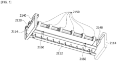
FIG. 5 is a rear perspective view illustrating the housing; -
FIG. 6 is a cross-sectional perspective view illustrating a skirt fixed to a holder; -
FIG. 7 is a cross-sectional perspective view illustrating the skirt fixed to the holder using a second mounting plate; -
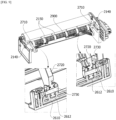
FIG. 8 is a view illustrating a driving link coupled to the holder; -
FIG. 9 is a view illustrating an elastic member rotated with a roller body; -
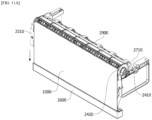
FIG. 10 is a view illustrating a state in which the skirt is retracted on a roller; and -
FIGS. 11A and11B are views illustrating a state in which the skirt is deployed. - Since the present invention allows various changes and has many embodiments, specific embodiments will be illustrated in the accompanying drawings and described. However, this is not intended to limit the present invention to the specific embodiments, and it is to be appreciated that all changes, equivalents, and substitutes that fall within the spirit and technical scope of the present invention are encompassed in the present invention.
- Although the terms "first," "second," and the like may be used herein to describe various elements, these elements should not be limited by these terms. These terms are only used to distinguish one element from another element. For example, a second element could be termed a first element, and a first element could similarly be termed a second element without departing from the scope of the present invention. The term "and/or" includes any one or any combination of a plurality of associated listed items.
- When a first element is referred to as being "connected" or "coupled" to a second element, it should be understood that the first element may be directly connected or coupled to the second element, or a third element may be present therebetween. In contrast, when a first element is referred to as being "directly connected" or "directly coupled" to a second element, it will be understood that there are no intervening elements.
- In a description of the embodiment, in a case in which any first element is described as being formed on or under a second element, such a description includes both a case in which the two elements are formed in direct contact with each other and a case in which the two elements are in indirect contact with each other with one or more third elements interposed between the two elements. In addition, when a first element is described as being formed on or under a second element, such a description may include a case in which the first element is formed at an upper side or a lower side with respect to the second element.
- Terminology used herein is for the purpose of describing particular embodiments only and is not intended to limit the present invention. The singular forms are intended to include the plural forms, unless the context clearly indicates otherwise. In the present specification, it should be further understood that the terms "comprise," "comprising," "include," and/or "including," used herein specify the presence of stated features, numbers, steps, operations, elements, and/or components but do not preclude the presence or addition of one or more other features, numbers, steps, operations, elements, components, and/or groups thereof.
- Unless otherwise defined, all terms including technical and scientific terms used herein have meanings which are the same as meanings generally understood by those skilled in the art. Terms, such as those defined in commonly used dictionaries, should be interpreted as having meanings that are consistent with their meanings in the context of the relevant art and will not be interpreted in an idealized or overly formal sense unless expressly so defined here.
- Hereinafter, a winding unit and a vehicle air skirt apparatus including the same will be described in detail with reference to the accompanying drawings, and components that are the same or correspond to each other will be denoted by the same reference numerals, and redundant descriptions thereof will be omitted.
-
FIG. 1 is a front perspective view illustrating a vehicle air skirt apparatus according to one embodiment of the present invention, andFIG. 2 is a rear perspective view illustrating the vehicle air skirt apparatus according to one embodiment of the present invention. - Referring to FIGS.
land 2, a vehicleair skirt apparatus 1 according to one embodiment of the present invention may be disposed in a bumper of a vehicle. The vehicleair skirt apparatus 1 may block a headwind from passing under the bumper of the vehicle bumper in a longitudinal direction of the vehicle. In this case, the longitudinal direction may be a direction from a passenger room (not shown) toward an engine room (not shown) of the vehicle or a direction opposite thereto. The vehicleair skirt apparatus 1 includes askirt 1000 for blocking inflow of a headwind and awinding unit 2000 for winding theskirt 1000. - The
skirt 1000 may have a rectangular shape. Theskirt 1000 may be formed of a material having waterproofness and flexibility. Theflexible skirt 1000 may be wound around aroller 2400 which will be described below. When theskirt 1000 is deployed by theroller 2400, theskirt 1000 may protrude to the outside of the bumper of the vehicle. More specifically, theskirt 1000 may protrude downward from the bumper and may be exposed to the outside of the vehicle. - The
skirt 1000 may block a headwind from being introduced into the vehicle. More specifically, theskirt 1000 may block foreign matter such as sand and a stone present on a road surface from coming into contact with a component disposed on a lower portion of the vehicle. In addition, thewaterproof skirt 1000 may block water from being introduced into the vehicle when the vehicle passes over a waterhole. -
FIG. 3 is an exploded perspective view illustrating the vehicle air skirt apparatus according to one embodiment of the present invention, andFIG. 4 is a front perspective view illustrating a housing.FIG. 5 is a rear perspective view illustrating the housing, andFIG. 6 is a cross-sectional perspective view illustrating a skirt fixed to a holder.FIG. 7 is a cross-sectional perspective view illustrating the skirt fixed to the holder using a second mounting plate, andFIG. 8 is a view illustrating a driving link coupled to the holder.FIG. 9 is a view illustrating an elastic member rotated with a roller body. - The winding
unit 2000 may wind theskirt 1000 for blocking inflow of a headwind generated when the vehicle travels. The windingunit 2000 may include ahousing 2100, acover 2200, anactuator 2300, aroller 2400, asecond mounting plate 2500, aholder 2600, adriving link 2700, ananti-slip link 2800, and a connectingshaft 2900. - Referring to
FIGS. 2 to 5 , thehousing 2100 may rotatably support theroller 2400 and afirst link 2710, which will be described below. Thehousing 2100 may include ahousing body 2110, afirst accommodation groove 2120, afirst support groove 2130, asecond support groove 2140, afirst support protrusion 2150, and asecond support protrusion 2160. - The
housing body 2110 may form an exterior of thehousing 2100. Thehousing body 2110 may include amain portion 2112 andside portions 2114. A length of themain portion 2112 may be greater than a length of theroller 2400 in a longitudinal direction. Themain portion 2112 may have a thickness sufficient for forming thefirst accommodation groove 2120. In addition, themain portion 2112 may support thefirst support protrusion 2150 and thesecond support protrusion 2160. Theside portions 2114 may be disposed on both side portions of themain portion 2112. Theside portions 2114 may support themain portion 2112. Theside portions 2114 and themain portion 2112 may form a space in which theholder 2600 is disposed. This may be structured to reduce a total height of the vehicleair skirt apparatus 1 in a height direction. In this case, the height direction may be a direction perpendicularly intersecting the longitudinal direction. - The
first accommodation groove 2120 may be formed in themain portion 2112 of thehousing body 2110. Thefirst accommodation groove 2120 may have a semicircular shape. Thefirst accommodation groove 2120 may rotatably accommodate aroller body 2410 of theroller 2400, which will be described below. - The
first support groove 2130 may be formed in theside portion 2114 of thehousing body 2110. Thefirst support groove 2130 may be connected to thefirst accommodation groove 2120. Thefirst support groove 2130 may have a semicircular shape. Thefirst support groove 2130 may rotatably support a rollingshaft part 2420 of theroller 2400, which will be described below. - The
second support groove 2140 may be formed in theside portion 2114 of thehousing body 2110. Thesecond support groove 2140 may be formed in a portion, which is not coupled to themain portion 2112, of theside portion 2114. Thesecond support groove 2140 may have a semicircular shape. In the longitudinal direction, thesecond support groove 2140 may be disposed at a position overlapping a hole formed in thefirst support protrusion 2150. Accordingly, thesecond support groove 2140 may be concentric with the hole formed in thefirst support protrusion 2150. As illustrated inFIG. 9 , thesecond support groove 2140 may rotatably support thefirst link 2710 of thedriving link 2700, which will be described below. - The
first support protrusion 2150 may be disposed on themain portion 2112. More specifically, thefirst support protrusion 2150 may be disposed on an outer surface of themain portion 2112. Thefirst support protrusion 2150 may be disposed between twoside portions 2114. Thefirst support protrusion 2150 may be provided as a plurality offirst support protrusions 2150 disposed on the outer surface of themain portion 2112 in the longitudinal direction. Thefirst support protrusion 2150 may have a hollow shape. Accordingly, thefirst support protrusion 2150 may rotatably support the connectingshaft 2900. - The
second support protrusion 2160 may be disposed on the outer surface of themain portion 2112. Thesecond support protrusion 2160 may be disposed below thefirst support protrusion 2150 in the height direction. Thesecond support protrusion 2160 may be provided as a plurality ofsecond support protrusions 2160 disposed on the outer surface of themain portion 2112 in the longitudinal direction. Thesecond support protrusion 2160 may protrude in a width direction. In this case, the width direction may be a direction intersecting the longitudinal direction. Thesecond support protrusion 2160 may rotatably support athird link 2810 of theanti-slip link 2800, which will be described below. - Referring to
FIGS. 1 to 3 , thecover 2200 may cover parts of theskirt 1000, theroller 2400, and thehousing 2100. Thecover 2200 may be formed by coupling a curved portion and a linear portion. Thecover 2200 may have a hollow shape. Thecover 2200 may prevent foreign matter from coming into contact with each component of theskirt 1000 and the windingunit 2000. A plurality of ribs for reinforcing rigidity may be disposed on an outer surface of thecover 2200. - Referring to
FIGS. 1 to 3 , theactuator 2300 may be disposed on any one of twoside portions 2114 of thehousing 2100. Theactuator 2300 may include anactuator body 2310 and afirst mounting plate 2320. Theactuator body 2310 may be connected to a power supply apparatus for supplying external power. Theactuator body 2310 may generate power when receiving a signal from the power supply apparatus. Theactuator body 2310 may be coupled to thefirst link 2710 of thedriving link 2700, which will be described below. - The
first mounting plate 2320 may be disposed between theside portion 2114 of thehousing 2100 and theactuator body 2310. Thefirst mounting plate 2320 may be fixed to theside portion 2114 of thehousing 2100 using a coupling member such as a bolt. Thefirst mounting plate 2320 may absorb vibrations generated by theactuator body 2310 and absorb vibrations generated by thehousing 2100. Accordingly, thefirst mounting plate 2320 may improve the stability of the vehicleair skirt apparatus 1 by absorbing vibrations of the vehicleair skirt apparatus 1. - Referring to
FIGS. 3 ,6 ,8 , and9 , theroller 2400 may be coupled to theskirt 1000 and wind theskirt 1000. Theroller 2400 may include theroller body 2410, the rollingshaft part 2420, anelastic member 2430, and acap 2440. - The
roller body 2410 may have a cylindrical shape. In addition, a plurality of ribs for reinforcing rigidity may be disposed on an outer surface of theroller body 2410 to prevent a phenomenon such as distortion when theroller body 2410 rotates. Theroller body 2410 may be rotatably disposed in thefirst accommodation groove 2120 of thehousing 2100. - The
roller body 2410 may include asecond accommodation groove 2412. As illustrated inFIG. 8 , thesecond accommodation groove 2412 may have a concave shape from the outer surface of theroller body 2410 toward a center of theroller body 2410. Thesecond accommodation groove 2412 may accommodate one end portion of theskirt 1000 and thesecond mounting plate 2500. In addition, theroller body 2410 may further include a protrusion coupled to theskirt 1000 and thesecond mounting plate 2500. Accordingly, the number of coupling members is decreased by theroller body 2410, and thus an effect of reducing manufacturing costs can be obtained. - The rolling
shaft part 2420 may be disposed on both end portions of theroller body 2410 in the longitudinal direction. The rolling shaft part may be rotatably disposed in thefirst support groove 2130 formed in theside portions 2114 of thehousing 2100 illustrated inFIG. 4 . The rollingshaft part 2420 may have a hollow shape. When theroller body 2410 coupled to theskirt 1000 rotates, the rollingshaft part 2420 may be guided by thefirst support groove 2130 of thehousing 2100 to rotate along theroller body 2410. - The
elastic member 2430 may be disposed in the rollingshaft part 2420. As illustrated inFIG. 6 , theelastic member 2430 may include a windingpart 2431, afirst end portion 2432, and asecond end portion 2433. Theelastic member 2430 including the windingpart 2431, thefirst end portion 2432, and thesecond end portion 2433 may be a torsion spring. - The winding
part 2431 may be wound around the rollingshaft part 2420 and maintained in a wound state. The windingpart 2431 may support thefirst end portion 2432 and thesecond end portion 2433. The windingpart 2431 may rotate with the rollingshaft part 2420. - The
first end portion 2432 may be disposed on one end portion of the windingpart 2431. Thefirst end portion 2432 may be supported by an additional groove connected to thefirst accommodation groove 2120 of thehousing 2100. As illustrated inFIG. 6 , a length of the additional groove connected to thefirst accommodation groove 2120 of thehousing 2100 is greater than a length of thefirst end portion 2432, and a width of the additional groove is smaller than the length of thefirst end portion 2432. Accordingly, a state in which thefirst end portion 2432 is fixed in the additional groove connected to thefirst accommodation groove 2120 of thehousing 2100 may be maintained. - The
second end portion 2433 may be disposed on the other end portion of the windingpart 2431. Thesecond end portion 2433 may protrude to the outside of the rollingshaft part 2420 through a hole formed in the rollingshaft part 2420, and a part of thesecond end portion 2433 protruding to the outside of the rollingshaft part 2420 may be fixed to theroller body 2410. Accordingly, when theroller body 2410 and the rollingshaft part 2420 rotate, thesecond end portion 2433 may rotate with theroller body 2410. - As illustrated in
FIG. 6 , when theroller body 2410 rotates to deploy theskirt 1000 in the height direction, thesecond end portion 2433 of theelastic member 2430 rotates with theroller body 2410. In this case, since thefirst end portion 2432 does not rotate, when theskirt 1000 is wound to be retracted, thesecond end portion 2433 may rotate theroller body 2410 in a direction opposite to a direction in which theskirt 1000 rotates to be deployed by a force for restoring thesecond end portion 2433 to a state before thesecond end portion 2433 is rotated. As described above, theelastic member 2430 may help restoring rotation of theroller 2400. - The
cap 2440 may be coupled to the rollingshaft part 2420. Thecap 2440 may prevent theelastic member 2430 disposed in the rollingshaft part 2420 from escaping outward from the rollingshaft part 2420. - Referring to
FIGS. 3 and8 , thesecond mounting plate 2500 may be provided as a plurality ofsecond mounting plates 2500. As illustrated inFIG. 8 , thesecond mounting plate 2500 may be coupled to one end portion of theskirt 1000. In addition, thesecond mounting plate 2500 may be disposed in thesecond accommodation groove 2412 of theroller body 2410. Thesecond mounting plate 2500 may be coupled to a protrusion formed on theroller 2400 and fixed to theroller 2400 and may be fixed to theroller body 2410 using a coupling member such as a bolt. In this case, the other end portion of theskirt 1000 may be fixed to theroller 2400 using a coupling member coupled to thesecond mounting plate 2500. - Referring to
FIGS. 3 ,7 , and9 , theholder 2600 may be coupled to an end portion of theskirt 1000. Theholder 2600 may be coupled to the end portion of theskirt 1000 and moved by thedriving link 2700 to pull or push theskirt 1000. Theholder 2600 may be disposed on a lower portion of thehousing 2100 in the height direction. More specifically, theholder 2600 may be disposed in a space formed by themain portion 2112 and theside portions 2114 of thehousing 2100. Theholder 2600 may include aholding block 2610 and acase 2620. - The holding
block 2610 may form an exterior of theholder 2600. The holdingblock 2610 may have a shape having a length in the longitudinal direction. The holdingblock 2610 may be in contact with one surface of one end portion of theskirt 1000, and theholding block 2610 and thecase 2620 may be coupled to one end portion of theskirt 1000. The holdingblock 2610 may include athird accommodation groove 2612 and athird support protrusion 2614. - The
third accommodation groove 2612 may have a concave shape from an outer surface of theholding block 2610 toward the inside of theholding block 2610. Thethird accommodation groove 2612 may be provided as a plurality ofthird accommodation grooves 2612 disposed in theholding block 2610 to be spaced apart from each other in the longitudinal direction. Thethird accommodation groove 2612 may accommodate an end portion of asecond link 2720 of thedriving link 2700, which will be described below. In addition, thethird accommodation groove 2612 may include apin 2730 of thedriving link 2700, which will be described below. - The
third support protrusion 2614 may be disposed between the plurality ofthird accommodation grooves 2612 in the longitudinal direction. Thethird support protrusion 2614 may protrude from the outer surface of theholding block 2610 in the width direction. Thethird support protrusion 2614 may be formed in a cylindrical shape. Thethird support protrusion 2614 may rotatably support afourth link 2820 of theanti-slip link 2800, which will be described below. - As illustrated in
FIG. 7 , thecase 2620 may be coupled to a part of the outer surface of theholding block 2610. Thecase 2620 and theholding block 2610 may be coupled to one end portion of theskirt 1000. Accordingly, thecase 2620 and theholding block 2610 may fix one end portion of theskirt 1000. - Referring to
FIGS. 2 ,3 , and9 , thedriving link 2700 may connect theholder 2600 and theactuator 2300 and move theholder 2600 using power generated by theactuator 2300. Thedriving link 2700 may be provided as a plurality of drivinglinks 2700 disposed inside theside portions 2114 of thehousing 2100 to be spaced apart from each other in the longitudinal direction. Thedriving link 2700 may include thefirst link 2710, thesecond link 2720, and thepin 2730. - As illustrated in
FIGS. 2 and9 , thefirst link 2710 may be coupled to theactuator body 2310 of theactuator 2300. Thefirst link 2710 may be coupled to the connectingshaft 2900. In addition, thefirst link 2710 may be rotatably supported by thefirst support groove 2130 formed in theside portion 2114 of thehousing 2100. Accordingly, when power is generated by theactuator 2300, thefirst link 2710 connected to theactuator body 2310 may rotate the connectingshaft 2900. When the connectingshaft 2900 rotates, the otherfirst link 2710 which is not connected to theactuator body 2310 may rotate. - One end portion of the
second link 2720 may be coupled to thefirst link 2710, and the other end portion thereof may be disposed in thethird accommodation groove 2612 formed in theholding block 2610 of theholder 2600. Thesecond link 2720 may be rotatably coupled to thefirst link 2710 using a coupling member such as a bolt. Accordingly, thesecond link 2720 may connect thefirst link 2710 and theholder 2600 and move in conjunction with movement of thefirst link 2710. - The
pin 2730 may be provided as a combination of a disc-shaped head and a cylindrical body. Thepin 2730 may pass through theholding block 2610 forming thethird accommodation groove 2612 of theholder 2600. Accordingly, thepin 2730 may rotatably couple thesecond link 2720 to theholder 2600. - The
pin 2730 may transfer a force generated by movement of thesecond link 2720 to theholder 2600. More specifically, when thesecond link 2720 may move in conjunction with the movement of thefirst link 2710 to press thepin 2730, thepin 2730 may press the holdingblock 2610 using a force of thesecond link 2720 pressing thepin 2730. Accordingly, the holdingblock 2610 may move in a direction in which theskirt 1000 is deployed or retracted in the height direction. That is, thepin 2730 may be a medium for transferring a force. Accordingly, thepin 2730 may preferably be formed of a rigid material. - Referring to
FIGS. 2 and3 , theanti-slip link 2800 may connect thehousing 2100 and theholder 2600 and prevent theskirt 1000 and theholder 2600 from being pushed back. Theanti-slip link 2800 may include thethird link 2810 and thefourth link 2820. - The
third link 2810 may be rotatably coupled to thesecond support protrusion 2160 of thehousing 2100. One end portion of thefourth link 2820 may be rotatably coupled to thethird link 2810 using a coupling member such as a bolt, and the other end portion thereof may be rotatably coupled to thethird support protrusion 2614 formed on theholding block 2610 of theholder 2600. - The
anti-slip link 2800 having such a structure may have a rotation center disposed in a direction different from thedriving link 2700. Accordingly, theanti-slip link 2800 may rotate in a direction different from thedriving link 2700, more specifically, in a direction intersecting a rotation direction of thedriving link 2700. - As illustrated in
FIG. 11B which will be described below, when theholding block 2610 moves downward from thehousing 2100 in the height direction, thethird link 2810 and thefourth link 2820 of theanti-slip link 2800 may be disposed to be substantially parallel to each other to block movement of theholding block 2610 in the width direction. Accordingly, movement of theskirt 1000 coupled to theholder 2600 in the width direction may be blocked so that an effect of preventing theskirt 1000 from being pushed back in the width direction by a headwind can be obtained. - Referring to
FIGS. 3 ,5 , and9 , the connectingshaft 2900 may have a cylindrical shape. A plurality of ribs for preventing damage when the connectingshaft 2900 rotates may be formed on an outer surface of the connectingshaft 2900. The connectingshaft 2900 may be rotatably disposed in thefirst support protrusion 2150 of thehousing 2100. The connectingshaft 2900 may be coupled to a plurality offirst links 2710 of thedriving link 2700. Accordingly, when thefirst links 2710 are rotated by power generated by theactuator 2300, the connectingshaft 2900 may rotate the otherfirst links 2710. - Hereinafter, an operation process of the vehicle
air skirt apparatus 1 will be described. -
FIG. 10 is a view illustrating a state in which the skirt is retracted on a roller, andFIGS. 11A and11B are views illustrating a state in which the skirt is deployed. - Referring to
FIGS. 1 to 11B , more specifically, inFIGS. 10 to 11B , in a state in which theskirt 1000 is not deployed in the height direction, theskirt 1000 is rolled around theroller body 2410 of theroller 2400 and retracted, and theholder 2600 is disposed in the space formed by themain portion 2112 and theside portions 2114 of thehousing 2100. - In this state, when power is supplied from an external power supply apparatus, the
actuator body 2310 generates power. When the power is generated by theactuator body 2310, thefirst link 2710 of thedriving link 2700 connected to theactuator body 2310 rotates. When thefirst link 2710 rotates, the connectingshaft 2900 connected to thefirst link 2710 rotates, and the otherfirst link 2710 connected to the connectingshaft 2900 also rotates with the connectingshaft 2900. - As described above, when the plurality of
first links 2710 rotate, thesecond link 2720 connected to thefirst link 2710 rotates in conjunction with the movement of thefirst link 2710. Thesecond link 2720 rotated by thefirst link 2710 presses thepin 2730, and thepin 2730 transfers a pressing force transferred from thesecond link 2720 to theholding block 2610 of theholder 2600. The holdingblock 2610 which receives the pressing force from thepin 2730 starts to move to a lower side of thehousing 2100 in the height direction. When theholding block 2610 moves, thecase 2620 of theholder 2600 and one end portion of theskirt 1000 fixed to theholder 2600 move to the lower side of thehousing 2100. - When one end portion of the
skirt 1000 starts to move to the lower side of thehousing 2100, theroller 2400 which fixes the other end portion of theskirt 1000 receives a force pulling theskirt 1000 to start to rotate about an axial center of the rollingshaft part 2420. Accordingly, as illustrated inFIG. 11A , theskirt 1000 may move to be exposed to the outside of the vehicle to block a headwind. - When the
holding block 2610 moves to the lower side of thehousing 2100 in the height direction by thesecond link 2720 and thepin 2730, thethird link 2810 and thefourth link 2820 of theanti-slip link 2800 rotate simultaneously. More specifically, thefourth link 2820 which rotates in conjunction with thethird link 2810 is rotatably supported by the holdingblock 2610. Accordingly, thethird link 2810 and thefourth link 2820, which are in deployed states, absorb a force generated by the holdingblock 2610 being pushed in the width direction to prevent theholding block 2610 from being pushed back in the width direction. Accordingly, vibrations of theholder 2600 and theskirt 1000 are reduced. - As described above, the
skirt 1000 of the vehicleair skirt apparatus 1 according to one embodiment of the present invention may be deployed or retracted in a direction intersecting a direction in which theroller 2400 is disposed in conjunction with movement of theholder 2600. Accordingly, since the vehicleair skirt apparatus 1 according to one embodiment of the present invention does not require an operation space disposed outward in the longitudinal direction of thehousing 2100 when compared to the conventional air skirt apparatus which rotates in the width direction to cover the lower end portion of the vehicle, collision with the bumper can be prevented. Accordingly, a repairing cost and time due to damage to the bumper and damage to the vehicleair skirt apparatus 1 can be reduced. - In addition, since the vehicle
air skirt apparatus 1 according to one embodiment of the present invention moves theskirt 1000 linearly in the height direction when compared to the conventional air skirt apparatus which rotates in the width direction to cover the lower end portion of the vehicle, a deployment time of theskirt 1000 can be shortened. Accordingly, the vehicleair skirt apparatus 1 according to one embodiment of the present invention may have an effect of blocking a headwind more quickly than the conventional air skirt apparatus. - According to one embodiment of the present invention, since an air skirt apparatus does not require additional operation space is in a width direction, damage to a bumper and a skirt due to collision with a bumper skin is prevented, and thus a repair cost and time can be reduced.
- In addition, according to one embodiment of the present invention, since an air skirt apparatus does not require additional operation space in a width direction, a space in which additional components are arranged to improve driving performance of a vehicle is secured, and thus the driving performance of the vehicle can be improved.
- While the present invention has been described above with reference to exemplary embodiments, it may be understood by those skilled in the art that various modifications and changes of the present invention may be made within a range not departing from the spirit and scope of the present invention defined by the appended claims. In addition, it should be interpreted that differences related to the modifications and changes fall within the scope of the present invention defined by the appended claims.
Claims (10)
- A winding unit configured to wind a skirt that blocks inflow of a headwind generated when a vehicle travels, the winding unit comprising:an actuator which generates power;a roller configured to couple to the skirt and wind the skirt;a holder configured to couple to an end portion of the skirt; anda driving link which connects the holder and the actuator and moves the holder using the power generated by the actuator.
- The winding unit of claim 1, wherein the holder is configured to pull or push the skirt such that the skirt is deployed or retracted in conjunction with movement of the holder in a direction intersecting a direction in which the roller is disposed.
- The winding unit of claim 1 or 2, wherein the skirt includes a material having waterproofness and flexibility.
- The winding unit of any one of claims 1 to 3, wherein the driving link includes:a first link coupled to the actuator;a second link which connects the first link and the holder and moves in conjunction with movement of the first link; anda pin which rotatably couples the second link to the holder and transfers a force generated by movement of the second link to the holder.
- A vehicle air skirt apparatus comprising:a skirt which blocks inflow of a headwind; anda winding unit which winds the skirt, the winding unit including an actuator which generates power, a roller which is coupled to the skirt and winds the skirt, a holder coupled to an end portion of the skirt, and a driving link which connects the holder and the actuator and moves the holder using the power generated by the actuator.
- The vehicle air skirt apparatus of claim 5, wherein the skirt is deployed or retracted in conjunction with movement of the holder in a direction intersecting a direction in which the roller is disposed.
- The vehicle air skirt apparatus of claim 5 or 6, wherein the skirt includes a material having waterproofness and flexibility.
- The vehicle air skirt apparatus of any one of claims 5 to 7, wherein the driving link includes:a first link coupled to the actuator;a second link which connects the first link and the holder and moves in conjunction with movement of the first link; anda pin which rotatably couples the second link to the holder and transfers a force generated by movement of the second link to the holder.
- The vehicle air skirt apparatus of claim 8, comprising a housing which rotatably supports the roller and the first link.
- The vehicle air skirt apparatus of claim 9, comprising an anti-slip link which connects the housing and the holder and prevents the skirt and the holder from being pushed back.
Applications Claiming Priority (1)
| Application Number | Priority Date | Filing Date | Title |
|---|---|---|---|
| KR1020230110573A KR20250029533A (en) | 2023-08-23 | 2023-08-23 | Winding unit and vehicel air skirt apparatus comprising the same |
Publications (2)
| Publication Number | Publication Date |
|---|---|
| EP4512701A1 true EP4512701A1 (en) | 2025-02-26 |
| EP4512701B1 EP4512701B1 (en) | 2026-03-04 |
Family
ID=89772338
Family Applications (1)
| Application Number | Title | Priority Date | Filing Date |
|---|---|---|---|
| EP24155041.7A Active EP4512701B1 (en) | 2023-08-23 | 2024-01-31 | Winding unit vehicle air skirt apparatus comprising the same |
Country Status (4)
| Country | Link |
|---|---|
| US (1) | US20250065964A1 (en) |
| EP (1) | EP4512701B1 (en) |
| KR (1) | KR20250029533A (en) |
| CN (1) | CN221969632U (en) |
Citations (4)
| Publication number | Priority date | Publication date | Assignee | Title |
|---|---|---|---|---|
| DE102018209474A1 (en) * | 2018-06-13 | 2019-12-19 | Audi Ag | motor vehicle |
| US20220153356A1 (en) * | 2020-11-13 | 2022-05-19 | Ford Global Technologies, Llc | Deflectable active air dam assembly and active air dam load response method |
| US20220315135A1 (en) * | 2021-03-31 | 2022-10-06 | Honda Motor Co., Ltd. | Flexible and Storable Active Spoiler System |
| KR20230110573A (en) | 2020-12-24 | 2023-07-24 | 프라마톰 게엠베하 | Mineralization of organic compounds by boron-doped-diamond electrodes during radionuclide removal process |
-
2023
- 2023-08-23 KR KR1020230110573A patent/KR20250029533A/en active Pending
-
2024
- 2024-01-26 US US18/423,753 patent/US20250065964A1/en active Pending
- 2024-01-31 EP EP24155041.7A patent/EP4512701B1/en active Active
- 2024-04-15 CN CN202420773511.6U patent/CN221969632U/en active Active
Patent Citations (4)
| Publication number | Priority date | Publication date | Assignee | Title |
|---|---|---|---|---|
| DE102018209474A1 (en) * | 2018-06-13 | 2019-12-19 | Audi Ag | motor vehicle |
| US20220153356A1 (en) * | 2020-11-13 | 2022-05-19 | Ford Global Technologies, Llc | Deflectable active air dam assembly and active air dam load response method |
| KR20230110573A (en) | 2020-12-24 | 2023-07-24 | 프라마톰 게엠베하 | Mineralization of organic compounds by boron-doped-diamond electrodes during radionuclide removal process |
| US20220315135A1 (en) * | 2021-03-31 | 2022-10-06 | Honda Motor Co., Ltd. | Flexible and Storable Active Spoiler System |
Also Published As
| Publication number | Publication date |
|---|---|
| CN221969632U (en) | 2024-11-08 |
| EP4512701B1 (en) | 2026-03-04 |
| KR20250029533A (en) | 2025-03-05 |
| US20250065964A1 (en) | 2025-02-27 |
Similar Documents
| Publication | Publication Date | Title |
|---|---|---|
| CN108791828B (en) | Expandable and retractable shock strut | |
| US6578872B2 (en) | Vehicle steering column including a pyrotechnic charge | |
| EP2210279B1 (en) | Solar cell array | |
| US4390193A (en) | Energy absorbing steering wheel assembly | |
| US20140326833A1 (en) | Directionally Controlled Elastically Deployable Roll-Out Array | |
| US20060125224A1 (en) | Impact absorbing steering column device for vehicle | |
| US20230046563A1 (en) | Z-fold solar array with curved substrate panels | |
| JP4354742B2 (en) | Vehicle steering column device | |
| US12187356B2 (en) | Vehicular aerodynamic device | |
| US4666107A (en) | Deployable space panel structure | |
| US20040046379A1 (en) | Steering column with tubular structure | |
| US20230042339A1 (en) | An assembly apparatus | |
| EP4512701A1 (en) | Winding unit vehicle air skirt apparatus comprising the same | |
| JP2009526686A (en) | Energy absorber for aircraft | |
| EP3277979B1 (en) | Accessory drive tensioner with improved arrangement of tensioner arm and biasing member | |
| EP1783051A1 (en) | Combination actuator latch mechanism | |
| US20080087129A1 (en) | Tilt And Telescopic Type Steering System For Vehicle Use | |
| JP2005112272A (en) | Fuel tank mounting structure | |
| JP3666710B2 (en) | Rocket movable nozzle | |
| US20240109610A1 (en) | Movable spoiler device | |
| GB2186240A (en) | Two-stage energy management unit for mounting vehicle bumpers | |
| CN113771548B (en) | A variable-diameter driving wheel and its method based on origami technology | |
| CN114347738A (en) | Arm mechanism and flight device | |
| KR100242054B1 (en) | Bumper Support for Vehicle | |
| JP3931419B2 (en) | Body bumper structure |
Legal Events
| Date | Code | Title | Description |
|---|---|---|---|
| PUAI | Public reference made under article 153(3) epc to a published international application that has entered the european phase |
Free format text: ORIGINAL CODE: 0009012 |
|
| STAA | Information on the status of an ep patent application or granted ep patent |
Free format text: STATUS: THE APPLICATION HAS BEEN PUBLISHED |
|
| AK | Designated contracting states |
Kind code of ref document: A1 Designated state(s): AL AT BE BG CH CY CZ DE DK EE ES FI FR GB GR HR HU IE IS IT LI LT LU LV MC ME MK MT NL NO PL PT RO RS SE SI SK SM TR |
|
| STAA | Information on the status of an ep patent application or granted ep patent |
Free format text: STATUS: REQUEST FOR EXAMINATION WAS MADE |
|
| 17P | Request for examination filed |
Effective date: 20250425 |
|
| GRAP | Despatch of communication of intention to grant a patent |
Free format text: ORIGINAL CODE: EPIDOSNIGR1 |
|
| STAA | Information on the status of an ep patent application or granted ep patent |
Free format text: STATUS: GRANT OF PATENT IS INTENDED |
|
| INTG | Intention to grant announced |
Effective date: 20250826 |
|
| RAP3 | Party data changed (applicant data changed or rights of an application transferred) |
Owner name: HYUNDAI MOBIS CO., LTD. |
|
| GRAS | Grant fee paid |
Free format text: ORIGINAL CODE: EPIDOSNIGR3 |
|
| P01 | Opt-out of the competence of the unified patent court (upc) registered |
Free format text: CASE NUMBER: UPC_APP_0014696_4512701/2025 Effective date: 20251126 |
|
| GRAA | (expected) grant |
Free format text: ORIGINAL CODE: 0009210 |
|
| STAA | Information on the status of an ep patent application or granted ep patent |
Free format text: STATUS: THE PATENT HAS BEEN GRANTED |
|
| AK | Designated contracting states |
Kind code of ref document: B1 Designated state(s): AL AT BE BG CH CY CZ DE DK EE ES FI FR GB GR HR HU IE IS IT LI LT LU LV MC ME MK MT NL NO PL PT RO RS SE SI SK SM TR |
|
| REG | Reference to a national code |
Ref country code: CH Ref legal event code: F10 Free format text: ST27 STATUS EVENT CODE: U-0-0-F10-F00 (AS PROVIDED BY THE NATIONAL OFFICE) Effective date: 20260304 Ref country code: GB Ref legal event code: FG4D |
|
| REG | Reference to a national code |
Ref country code: IE Ref legal event code: FG4D |
|
| REG | Reference to a national code |
Ref country code: DE Ref legal event code: R096 Ref document number: 602024002883 Country of ref document: DE |