EP4512669A1 - Exterior decoration assembly and automobile - Google Patents
Exterior decoration assembly and automobile Download PDFInfo
- Publication number
- EP4512669A1 EP4512669A1 EP23830375.4A EP23830375A EP4512669A1 EP 4512669 A1 EP4512669 A1 EP 4512669A1 EP 23830375 A EP23830375 A EP 23830375A EP 4512669 A1 EP4512669 A1 EP 4512669A1
- Authority
- EP
- European Patent Office
- Prior art keywords
- fixing member
- exterior decoration
- mounting
- hole
- mounting hole
- Prior art date
- Legal status (The legal status is an assumption and is not a legal conclusion. Google has not performed a legal analysis and makes no representation as to the accuracy of the status listed.)
- Pending
Links
Images


Classifications
-
- B—PERFORMING OPERATIONS; TRANSPORTING
- B60—VEHICLES IN GENERAL
- B60R—VEHICLES, VEHICLE FITTINGS, OR VEHICLE PARTS, NOT OTHERWISE PROVIDED FOR
- B60R13/00—Elements for body-finishing, identifying, or decorating; Arrangements or adaptations for advertising purposes
- B60R13/04—External Ornamental or guard strips; Ornamental inscriptive devices thereon
-
- B—PERFORMING OPERATIONS; TRANSPORTING
- B60—VEHICLES IN GENERAL
- B60J—WINDOWS, WINDSCREENS, NON-FIXED ROOFS, DOORS, OR SIMILAR DEVICES FOR VEHICLES; REMOVABLE EXTERNAL PROTECTIVE COVERINGS SPECIALLY ADAPTED FOR VEHICLES
- B60J1/00—Windows; Windscreens; Accessories therefor
- B60J1/008—Windows; Windscreens; Accessories therefor of special shape, e.g. beveled edges, holes for attachment, bent windows, peculiar curvatures such as when being integrally formed with roof, door, etc.
Definitions
- the present disclosure relates to the field of automotive technology, and in particular, to an exterior decoration assembly and an automobile.
- Plastic exterior decoration members on the glass in the exterior decoration assembly are mostly integrated with the glass by means of tape, polyurethane (PU) glue, hot melt sticks and bars, claws and the like. After integration, it is impossible to be disassembled and forcible disassembly will cause damage to the exterior decoration members.
- an assembly structure is provided on the installation surface of the glass, and the exterior decoration members are installed with the glass through the assembly structure. In this case, after the exterior decoration members and the glass are assembled, the flush between the exterior decoration members and the glass is relatively large, which thus increases wind noise and also affects the installation of other components.
- the present disclosure relates to an exterior decoration assembly, including a glass, a first fixing member, an exterior decoration member and a second fixing member.
- the glass includes a mounting surface and a rear surface opposite to the mounting surface, and the glass is provided with a mounting hole extending through the mounting surface.
- At least a partial structure of the first fixing member is provided in the mounting hole and fixedly connected to the glass, and the first fixing member is located on a side of the mounting surface facing the rear surface along an axial direction of the mounting hole.
- the exterior decoration member is located on a side where the mounting surface is located, and the exterior decoration member is connected to a side of the first fixing member adjacent to the mounting surface by the second fixing member.
- a partial structure of the first fixing member protrudes from the mounting surface along the mounting hole and is connected to the second fixing member.
- the exterior decoration member is provided with a connection hole correspondingly connected to the mounting hole, and one end of the first fixing member is fixedly provided in the connection hole, and another end of the second fixing member extends through the connection hole, extends into the mounting hole, and is detachably connected to the first fixing member.
- connection hole is a stepped hole
- one end of the second fixing member is limitedly fitted with a step surface of the stepped hole
- another end of the second fixing member extends through the stepped hole, extends into the mounting hole, and is detachably connected to the first fixing member.
- the exterior decoration member is provided with a mounting groove, and the connection hole extends through a bottom wall of the mounting groove, and the exterior decoration assembly further includes a flip cover movably provided on the exterior decoration member and configured to open or close the mounting groove.
- the exterior decoration member covers the mounting surface.
- a sealing member is provided between a peripheral side of a partial structure of the exterior decoration member covering the mounting surface and the mounting surface.
- one of the first fixing member and the second fixing member is provided with an external thread structure, and another one is provided with an internal thread hole, and the external thread structure is fitted and connected to the internal thread hole; or one of the first fixing member and the second fixing member is a first snap-fit member, and another one is a second snap-fit member in a snap-fit cooperation with the second snap-fit member.
- a number of the mounting hole, a number of the first fixing member, and a second fixing member is at least two and corresponds one to one; a part of the first fixing member is provided with an external thread structure, a corresponding part of the second fixing member is provided with an internal thread hole matching with the external thread structure, a remaining part of the first fixing member is provided with a first snap-fit member, and a remaining part of the second fixing member corresponding to the remaining part of the first fixing member is provided with a second snap-fit member in a snap-fit cooperation with the first snap-fit member.
- the present disclosure also involves an automobile, including the exterior decoration assembly as described in any one of the above embodiments.
- first and second are used for descriptive purposes only, which cannot be construed as indicating or implying a relative importance, or implicitly specifying the number of the indicated technical features.
- the features defined with “first” and “second” may explicitly or implicitly include one or more features.
- a plurality of means two or more, such as two or three, unless otherwise defined explicitly and specifically.
- the exterior decoration assembly includes glass and an exterior decoration member.
- Traditional glass and exterior decoration member are generally integrated by means of tape or hot melt sticks and bars, and it is impossible to be disassembled.
- the glass and the exterior decoration member are generally assembled through structures such as hooks.
- the assembly structures such as hooks are provided between the glass and the exterior decoration member, making the flush between the glass and the exterior decoration member after assembly large, thus affecting the installation of other components.
- this present disclosure provides an exterior decoration assembly.
- the structure of the exterior decoration member and the glass after assembly has a low wind noise, and does not affect the mounting of other components.
- the exterior decoration member and the glass can be disassembly.
- FIG. 1 is a top view showing an exterior decoration assembly 10 with a flip cover 600 in an open state.
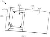
- FIG. 2 is a perspective view showing the exterior assembly 10 with the flip cover 600 in an open state.
- FIG. 3 is a cross-sectional view taken along line A-A in FIG. 1 .
- FIG. 4 is a schematic view showing the glass 100 on a side of a mounting surface 100.
- the exterior decoration assembly 10 includes a glass 100, a first fixing member 200, an exterior decoration member 400, and a second fixing member 300.
- the glass 100 includes a mounting surface 120 and a rear surface 130 opposite to the mounting surface 120, and the glass 100 is provided with a mounting hole 110 extending through the mounting surface 120.
- the firs fixing member 200 is connected to the glass 100, and at least a partial structure of the first fixing member 200 is provided in the mounting hole 110.
- the exterior decoration member 400 is located on a side where the mounting surface 120 is located, and the exterior decoration member 400 is connected to a side of the first fixing member 200 adjacent to the mounting surface 120 by the second fixing member 300.
- the detachable assembly of the glass 100 and the exterior decoration member 400 can be achieved by connecting the first fixing member 200 and the second fixing member 300.
- the partial structure of the first fixing member 200 extends into the mounting hole 110, compared with the conventional exterior decoration assembly 10 in which the glass 100 and the exterior decoration 400 are connected by a connection structure provided between the glass 100 and the exterior decoration member 400, the surface difference between the exterior decoration 400 and the glass 100 in the present disclosure after connected by the first fixing member 200 and the second fixing member 300 will be relatively small, and the exterior decoration member 400 occupies a relatively small space when assembled, thereby reducing wind noise and provide a relatively higher freedom in styling design.
- the partial structure of the first fixing member 200 can protrude from the mounting surface 120.
- the first fixing member 200 can be completely located on the side of the mounting surface 120 facing the rear surface 130.
- the partial structure of the first fixing member 200 protrudes from the mounting surface 120 along the mounting hole 110 and is connected to the second fixing member 300. Further, compared with the conventional method of locating the first fixing member 200 completely on the mounting surface 120, in this embodiment, the partial structure of the first fixing member 200 protrudes from the mounting surface 120, which can reduce the surface difference between the exterior decoration member 400 and the mounting surface 120 to a certain extent.
- the first fixing member 200 includes a main body part 210 and a fixing part 220 that are connected to each other.
- a volume of the main body part 210 is greater than a volume of the fixing part 220.
- the main body part 210 is located on a side of the mounting surface 120 facing the rear surface 130, and the partial structure of the fixing part 220 extends out of the mounting hole 110 and is connected to the second fixing member 300.
- the main body part 210 with greater volume is provided on the side of the mounting surface 120 facing the rear surface 130, and the fixing part 220 protrudes from the mounting hole 110 and is connected to the second fixing member 300, which can reduce the space occupied by the first fixing member 200 to a certain extent, and thus reduce the surface difference between the exterior decoration member 400 and the glass 100.
- the exterior decoration member 400 also occupies a relatively small space during assembly, thereby reducing wind noise and providing a relatively higher freedom in styling design.
- the first fixing member 200 is located on the side of the mounting surface 120 facing the rear surface 130.
- One end of the second fixing member 300 is connected to the exterior decoration member 400, the second fixing member 300 is connected to the exterior decoration member 400, and the other end of the second fixing member 300 extends into the mounting hole 110 from the side of the glass 100 locating on the mounting surface 120 and is detachably connected to the first fixing member 200.
- the axial direction of the mounting hole 110 refers to the L direction.
- the first fixing member 200 being located on the side of the mounting surface 120 facing the rear surface 130 means that, in the axial direction of the mounting hole 110, the first fixing member 200 is located below the mounting surface 120 in the viewing angle of FIG. 3 .
- the first fixing member 200 being located below the mounting surface 120 means that the first fixing member 200 does not protrude from the side of the mounting surface 120 relative to the mounting surface 120. In this case, when the first fixing member 200 extends into the mounting hole 110, the surface difference between the glass 100 and the exterior decoration member 400 can be reduced as much as possible.
- the surface difference between the glass 100 and the exterior decoration member 400 refers to a distance between a side surface of the exterior decoration member 400 facing the mounting surface 120 and the mounting surface 120 when the exterior decoration member 400 is assembled with the glass 100 through the second mounting member and the first mounting member.
- the smaller the distance the smaller the surface difference between the exterior decoration member 400 and the glass 100. In other words, the smaller the distance, the closer of the assembly between the exterior decoration member 400 and the glass 100.
- the detachable assembly of the glass 100 and the exterior decoration member 400 is achieved by connecting the first fixing member 200 and the second fixing member 300.
- the first fixing member 200 is located on the side of the mounting surface 120 facing the rear surface 130 in the axial direction of the mounting hole 110, which means that the first fixing member 200 does not protrude relative to the mounting surface 120, therefore, the surface difference between the exterior decoration member 400 and the glass 100 is relatively small when the second fixing member 300 extends from the side of the glass 100 locating on the mounting surface 120 into the mounting hole 110 and is connected to the first fixing member 200, and the exterior decoration member 400 also occupies a relatively smaller space when assembled, thereby reducing wind noise and providing a relatively higher freedom in styling design.
- one of the first fixing member 200 and the second fixing member 300 is provided with an external thread structure, and the other one of the first fixing member 200 and the second fixing member 300 is provided with an internal thread hole, and the first fixing member 200 and the second fixing member 300 is connected by cooperation of the external thread structure and the internal thread hole.
- the first fixing member 200 is a bolt
- the second fixing part 300 is a nut structure.
- the nut part of the nut structure is provided in the mounting hole 110.
- One end of the bolt is connected to the exterior decoration member 400, and the other end extends into the mounting hole 110 and is screwed with the nut, thereby achieving detachable assembly between the exterior decoration member 400 and the glass 100.
- first fixing member 200 and the second fixing member 300 can both be snap-fit members.
- first fixing member 200 is a first snap-fit member
- second fixing member 300 is a second snap-fit member
- the detachable assembly between the exterior decoration member 400 and the glass 100 can be achieved by snap-fit cooperation of the first snap-fit member and the second snap-fit member.
- the exterior decoration member 400 covers the mounting surface 120.
- a sealing member is provided between a peripheral side of a partial structure of the exterior decoration member 400 covering the mounting surface 120 and the mounting surface 120. In this way, the waterproof and dustproof function is achieved by providing the seal member.
- the seal member can be a foam strip.
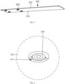
- FIG. 5 is a schematic view of the glass 100 in a viewing angle of the rear surface 130.
- FIG. 6 is a partially enlarged view of A in FIG. 4 .
- the mounting hole 110 extends from the mounting surface 120 to the rear surface 130 along a thickness direction of the glass 100.
- a partial structure of the first fixing member 120 extends into the mounting hole 110 from a side of the rear surface 130, and a remaining structure of the first fixing member 200 is provided outside the mounting hole 110 and is located on the side of the rear surface 130.
- providing the first fixing member 200 on the rear surface 130 can avoid the problem of a larger surface difference between the exterior decoration member 400 and the glass 100 due to the arrangement of the first fixing member 200 between the glass 100 and the exterior decoration member 400.
- the exterior decoration assembly 10 further includes an encapsulation 500.
- the encapsulation 500 is connected to the rear surface 130, and a structure of the first fixing member 200 located outside the mounting hole 110 is provided inside the encapsulation 500.
- the encapsulation 500 is configured to cover the glass 100.
- the first fixing member 200 and the encapsulation 500 can be integrally formed by injection molding, such that the partial structure of the first fixing member 200 is provided inside the encapsulation 500.
- a corresponding receiving groove can also be provided inside the encapsulation 500, and the partial structure of the first fixing member 200 can be fixedly provided inside the receiving groove.
- the main body part 210 is provided in the encapsulation 500.
- the glass 100, the first fixing member 200, and the encapsulation 500 are integrally formed.
- the glass 100, the first fixing member 200, and the encapsulation 500 can be integrally formed by injection molding.
- the exterior decoration member 400 is provided with a connection hole 412, which is correspondingly connected to the mounting hole 110.
- One end of the first fixing member 200 is fixedly provided in the connection hole 412, and the other end of the second fixing member 300 extends through the connection hole 412, extends into the mounting hole 110, and is detachably connected to the first fixing member 200.
- connection hole 412 is a stepped hole in communication with the mounting hole 110 correspondingly.
- One end of the second fixing member 300 is limitedly fitted with a step surface of the stepped hole, and the other end of the second fixing member 300 extends through the stepped hole, extends into the mounting hole 110, and is detachably connected to the first fixing member 200.
- the second fixing member 300 is fixed on the installation member by limiting fit with the stepped surface of the stepped hole, and the second fixing member 300 is connected to the first fixing member 200 by extending into the mounting hole 110 to achieve connection to the glass 100.
- the exterior decoration member 400 is provided with a mounting groove 410, and the connection hole 412 extends through a bottom wall of the mounting groove 410.
- the exterior decoration assembly 10 further includes a flip cover 600.
- the flip cover 600 is movably provided on the exterior decoration member 400 and configured to open or close the mounting groove 410. After the assembly of the first fixing member 200 and the second fixing member 300 is completed, the mounting groove 410 can be closed by the flip cover 600. As such, on the one hand, the second fixing member 300 can be protected, and on the other hand, a more appeal appearance can be presented.
- the number of the mounting hole 110, the number of the first fixing member 200, and the second fixing member 300 are at least two and correspond one to one.
- a part of the first fixing member is provided with an external thread structure
- a corresponding part of the second fixing member 300 is provided with an internal thread hole matching with the external thread structure
- a remaining part of the first fixing member 200 is provided with a first snap-fit member
- a remaining part of the second fixing member 300 corresponding to the remaining part of the first fixing member is provided with a second snap-fit member in a snap-fit cooperation with the first snap-fit member.
- the glass 100 and the exterior decoration member 400 are connected by a combination of screw connection and snap-fit cooperation.
- the mounting groove 410 is a square groove.
- stepped holes are correspondingly provided at four corners of the mounting groove 410.
- four corresponding mounting holes are also provided on the glass 100, and four first fixing members 200 and four second fixing member 300 are both provided, correspondingly.
- Each first fixing member 200 is correspondingly provided in each mounting hole 110, and each second fixing member 300 correspondingly extends through each stepped hole and is connected to the first fixing member 200 located in the mounting hole 110.
- the number of the stepped hole, mounting hole 110, first fixing member 200 and second fixing member 300 can also be 1, 2, 3, 5 or more.
- the number of the stepped hole, mounting hole 110, first fixing member 200 and second fixing member 300 can be configured according to specific needs, for example, according to the size of the exterior decoration member 400 and the size of the glass 100.
- the distribution manner of the stepped hole and the mounting hole 110 can also be configured as needed. For example, they can be provided at intervals along the same direction, or can be surrounded to form a circle or other irregular shapes.
- the flip cover 600 is movably provided on the exterior decoration member 400.
- the flip cover 600 can be slidably mounted on the exterior decoration member 400, or can also be rotatably mounted on the exterior decoration member 400.
- the exterior assembly 10 further includes a locking structure.
- the flip cover 600 covers the mounting groove 410, the flip cover 600 is locked on the exterior decoration member 400 through the locking structure.
- the locking structure is unlocked to open the flip cover 600.
- the locking structure may be a snap-fit structure.
- the flip cover 600 is provided with a protrusion structure, and the exterior decoration member 400 is provided with a groove structure.
- the flip cover 600 is provided with a groove structure, and the exterior decoration member 400 is provided with a protrusion structure, and the locking fit between the flip cover 600 and the exterior decoration member 400 can be achieved through the snap-fit cooperation between the groove and the protrusion.
- the locking structure may be a magnetic attraction structure.
- the flip cover 600 is provided with a first magnetic attraction portion
- the exterior decoration member 400 is provided with a second magnetic attraction portion
- the first magnetic attraction portion and the second magnetic attraction portion have opposite magnetism, such that the locking fit between the flip cover 600 and the exterior decoration member 400 can be achieved by magnetic attraction cooperation between the first magnetic attraction portion and the second magnetic attraction portion.
- the present disclosure also relates to an automobile, including the exterior decoration assembly 10 as described in any one of the above embodiments.
- the above-mentioned automobile includes the exterior decoration assembly 10 of any one of the aforementioned embodiments. Therefore, in the automobile, the detachable assembly of the glass 100 and the exterior decoration member 400 can be achieved by connecting the first fixing member 200 to the second fixing member 300.
- the first fixing member 200 is located below the mounting surface 120 in the axial direction of the mounting hole 110, which means that the first fixing part 200 does not protrude relative to the mounting surface 120. Therefore, when the second fixing member 300 extends from the side of the glass 100 located on the mounting surface 120 into the mounting hole 110 and is connected to the first fixing member 200, the surface difference between the exterior decoration member 400 and the glass 100 is small, and the exterior decoration member 400 occupies a relatively smaller space during assembly, thus not affecting the normal assembly of other components.
- the terms “install”, “connect”, “join”, and “fix” should be understood in a broad sense. For example, they may refer to a fixed connection, a detachable connection, or an integral connection; may refer to a mechanical connection or electrical connection; and may refer to a direct connection, an indirect connection via an intermediate medium, an internal connection between two elements, or interaction between two elements. Those of ordinary skill in the art can understand specific meanings of these terms in the present disclosure according to specific situations.
- a first feature being “on” or “under” a second feature may be the case that the first feature is in direct contact with the second feature, or the first feature is in indirect contact with the second feature via an intermediate medium.
- the expression the first feature being “over”, “above” and “on top of” the second feature may be the case that the first feature is directly above or obliquely above the second feature, or only means that the level of the first feature is higher than that of the second feature.
- the expression the first feature being "below”, “underneath” or “under” the second feature may be the case that the first feature is directly underneath or obliquely underneath the second feature, or only means that the level of the first feature is lower than that of the second feature.
Landscapes
- Engineering & Computer Science (AREA)
- Mechanical Engineering (AREA)
- Vehicle Interior And Exterior Ornaments, Soundproofing, And Insulation (AREA)
Abstract
Description
- This application claims priority to
Chinese Patent Application No. 2022107637833, entitled "EXTERIOR DECORATION ASSEMBLY AND AUTOMOBILE" and filed on June 30, 2022 - The present disclosure relates to the field of automotive technology, and in particular, to an exterior decoration assembly and an automobile.
- Plastic exterior decoration members on the glass in the exterior decoration assembly are mostly integrated with the glass by means of tape, polyurethane (PU) glue, hot melt sticks and bars, claws and the like. After integration, it is impossible to be disassembled and forcible disassembly will cause damage to the exterior decoration members. In addition, in some exterior decoration assemblies, an assembly structure is provided on the installation surface of the glass, and the exterior decoration members are installed with the glass through the assembly structure. In this case, after the exterior decoration members and the glass are assembled, the flush between the exterior decoration members and the glass is relatively large, which thus increases wind noise and also affects the installation of other components.
- According to various embodiments of the present disclosure, an exterior decoration assembly and an automobile are provided.
- The technical solution is as follows.
- In one aspect, the present disclosure relates to an exterior decoration assembly, including a glass, a first fixing member, an exterior decoration member and a second fixing member. The glass includes a mounting surface and a rear surface opposite to the mounting surface, and the glass is provided with a mounting hole extending through the mounting surface. At least a partial structure of the first fixing member is provided in the mounting hole and fixedly connected to the glass, and the first fixing member is located on a side of the mounting surface facing the rear surface along an axial direction of the mounting hole. The exterior decoration member is located on a side where the mounting surface is located, and the exterior decoration member is connected to a side of the first fixing member adjacent to the mounting surface by the second fixing member.
- The technical solution is further illustrated below.
- In one of the embodiments, a partial structure of the first fixing member protrudes from the mounting surface along the mounting hole and is connected to the second fixing member.
- In one of the embodiments, the first fixing member includes a main body part and a fixing part that are connected to each other, a volume of the main body part is greater than a volume of the fixing part, the main body part is located on a side of the mounting surface facing the rear surface, and a partial structure of the fixing part extends out of the mounting hole and is connected to the second fixing member.
- In one of the embodiments, along an axial direction of the mounting hole, the first fixing member is located on a side of the mounting surface facing the rear surface, and the second fixing member is configured as being capable of being detachably connected to the first fixing member by extending into the mounting hole along a side of the mounting surface, such that the exterior decoration member is connected to the glass.
- In one of the embodiments, the mounting hole extends from the mounting surface to the rear surface along a thickness direction of the glass, and a partial structure of the first fixing member extends into the mounting hole from a side of the rear surface, and a remaining structure of the first fixing member is provided outside the mounting hole and located on the side of the rear surface.
- In one of the embodiments, the exterior decoration assembly further includes an encapsulation connected to the rear surface, and the structure of the first fixing member located outside the mounting hole is provided inside the encapsulation.
- In one of the embodiments, the glass, the first fixing member and the encapsulation are integrally formed.
- In one of the embodiments, the exterior decoration member is provided with a connection hole correspondingly connected to the mounting hole, and one end of the first fixing member is fixedly provided in the connection hole, and another end of the second fixing member extends through the connection hole, extends into the mounting hole, and is detachably connected to the first fixing member.
- In one of the embodiments, the connection hole is a stepped hole, one end of the second fixing member is limitedly fitted with a step surface of the stepped hole, and another end of the second fixing member extends through the stepped hole, extends into the mounting hole, and is detachably connected to the first fixing member.
- In one of the embodiments, the exterior decoration member is provided with a mounting groove, and the connection hole extends through a bottom wall of the mounting groove, and the exterior decoration assembly further includes a flip cover movably provided on the exterior decoration member and configured to open or close the mounting groove.
- In one of the embodiments, the exterior decoration member covers the mounting surface.
- In one of the embodiments, a sealing member is provided between a peripheral side of a partial structure of the exterior decoration member covering the mounting surface and the mounting surface.
- In one of the embodiments, one of the first fixing member and the second fixing member is provided with an external thread structure, and another one is provided with an internal thread hole, and the external thread structure is fitted and connected to the internal thread hole;
or one of the first fixing member and the second fixing member is a first snap-fit member, and another one is a second snap-fit member in a snap-fit cooperation with the second snap-fit member. - In one of the embodiments, a number of the mounting hole, a number of the first fixing member, and a second fixing member is at least two and corresponds one to one;
a part of the first fixing member is provided with an external thread structure, a corresponding part of the second fixing member is provided with an internal thread hole matching with the external thread structure, a remaining part of the first fixing member is provided with a first snap-fit member, and a remaining part of the second fixing member corresponding to the remaining part of the first fixing member is provided with a second snap-fit member in a snap-fit cooperation with the first snap-fit member. - In another aspect, the present disclosure also involves an automobile, including the exterior decoration assembly as described in any one of the above embodiments.
- In order to more clearly illustrate the technical solutions in embodiments of the present disclosure or the conventional art, the accompanying drawings used in the description of the embodiments or the conventional art will be briefly introduced below. It is apparent that, the accompanying drawings in the following description are only some embodiments of the present disclosure, and other drawings can be obtained by those of ordinary skill in the art from the provided drawings without creative efforts.
-
FIG. 1 is a top view showing an exterior decoration assembly with a flip cover in an open state according to one embodiment of the present disclosure; -
FIG. 2 is a perspective view showing an exterior decoration assembly with a flip cover in an open state according to one embodiment; -
FIG. 3 is a cross-sectional view taken along line A-A inFIG. 1 ; -
FIG. 4 is a schematic view showing a glass on a side of a mounting surface according to one embodiment; -
FIG. 5 is a schematic view of the glass in a viewing angle of a rear surface according to one embodiment; -
FIG. 6 is a partially enlarged view of A inFIG. 4 . - 10. exterior decoration assembly; 100. glass; 110. mounting hole; 120. mounting surface; 130. rear surface; 200. first fixing member; 210. main body part; 220. fixing part; 300. second fixing member; 400. exterior decoration member; 410. mounting groove; 412. connection hole; 500. encapsulation; 600. flip cover.
- The technical solutions in the embodiments of the present disclosure will be described clearly and completely below with reference to the accompanying drawings in the embodiments of the present disclosure. The described embodiments are merely some of rather than all of the embodiments of the present disclosure. All other embodiments acquired by those skilled in the art without creative efforts based on the embodiments of the present disclosure shall fall within the protection scope of the present disclosure.
- In the description of the present disclosure, it should be understood that, the orientation or position relationships indicated by the terms "central", "longitudinal", "transverse", "length", "width", "thickness", "upper", "lower", "front", "back", "left", "right", "vertical", "horizontal", "top", "bottom", "inner", "outer", "clockwise", "counterclockwise", "axial", "radial", "circumferential", and the like are based on the orientation or position relationships shown in the accompanying drawings and are intended to facilitate the description of the present disclosure and simplify the description only, rather than indicating or implying that the apparatus or element referred to must have a particular orientation or be constructed and operated in a particular orientation, and therefore are not to be interpreted as limiting the present disclosure.
- In addition, the terms "first" and "second" are used for descriptive purposes only, which cannot be construed as indicating or implying a relative importance, or implicitly specifying the number of the indicated technical features. Thus, the features defined with "first" and "second" may explicitly or implicitly include one or more features. In the description of the present disclosure, "a plurality of" means two or more, such as two or three, unless otherwise defined explicitly and specifically.
- The exterior decoration assembly includes glass and an exterior decoration member. Traditional glass and exterior decoration member are generally integrated by means of tape or hot melt sticks and bars, and it is impossible to be disassembled. In addition, in some exterior decoration assemblies, the glass and the exterior decoration member are generally assembled through structures such as hooks. The assembly structures such as hooks are provided between the glass and the exterior decoration member, making the flush between the glass and the exterior decoration member after assembly large, thus affecting the installation of other components.
- In view of this, this present disclosure provides an exterior decoration assembly. In the exterior decoration assembly, the structure of the exterior decoration member and the glass after assembly has a low wind noise, and does not affect the mounting of other components. Moreover, the exterior decoration member and the glass can be disassembly.
-
FIG. 1 is a top view showing anexterior decoration assembly 10 with aflip cover 600 in an open state.FIG. 2 is a perspective view showing theexterior assembly 10 with theflip cover 600 in an open state.FIG. 3 is a cross-sectional view taken along line A-A inFIG. 1 .FIG. 4 is a schematic view showing theglass 100 on a side of a mountingsurface 100. - Referring to
FIGS. 1 to 4 , in one embodiment, theexterior decoration assembly 10 includes aglass 100, a first fixingmember 200, anexterior decoration member 400, and asecond fixing member 300. Theglass 100 includes a mountingsurface 120 and arear surface 130 opposite to the mountingsurface 120, and theglass 100 is provided with a mountinghole 110 extending through the mountingsurface 120. Thefirs fixing member 200 is connected to theglass 100, and at least a partial structure of the first fixingmember 200 is provided in the mountinghole 110. Theexterior decoration member 400 is located on a side where the mountingsurface 120 is located, and theexterior decoration member 400 is connected to a side of the first fixingmember 200 adjacent to the mountingsurface 120 by the second fixingmember 300. - During use, the detachable assembly of the
glass 100 and theexterior decoration member 400 can be achieved by connecting the first fixingmember 200 and the second fixingmember 300. In addition, since the partial structure of the first fixingmember 200 extends into the mountinghole 110, compared with the conventionalexterior decoration assembly 10 in which theglass 100 and theexterior decoration 400 are connected by a connection structure provided between theglass 100 and theexterior decoration member 400, the surface difference between theexterior decoration 400 and theglass 100 in the present disclosure after connected by the first fixingmember 200 and the second fixingmember 300 will be relatively small, and theexterior decoration member 400 occupies a relatively small space when assembled, thereby reducing wind noise and provide a relatively higher freedom in styling design. - It should be noted that, the partial structure of the first fixing
member 200 can protrude from the mountingsurface 120. Alternatively, along an axial direction of the mountinghole 110, the first fixingmember 200 can be completely located on the side of the mountingsurface 120 facing therear surface 130. - For example, in some embodiments, the partial structure of the first fixing
member 200 protrudes from the mountingsurface 120 along the mountinghole 110 and is connected to the second fixingmember 300. Further, compared with the conventional method of locating the first fixingmember 200 completely on the mountingsurface 120, in this embodiment, the partial structure of the first fixingmember 200 protrudes from the mountingsurface 120, which can reduce the surface difference between theexterior decoration member 400 and the mountingsurface 120 to a certain extent. - In some embodiments, the first fixing
member 200 includes amain body part 210 and a fixingpart 220 that are connected to each other. A volume of themain body part 210 is greater than a volume of the fixingpart 220. Themain body part 210 is located on a side of the mountingsurface 120 facing therear surface 130, and the partial structure of the fixingpart 220 extends out of the mountinghole 110 and is connected to the second fixingmember 300. As such, themain body part 210 with greater volume is provided on the side of the mountingsurface 120 facing therear surface 130, and the fixingpart 220 protrudes from the mountinghole 110 and is connected to the second fixingmember 300, which can reduce the space occupied by the first fixingmember 200 to a certain extent, and thus reduce the surface difference between theexterior decoration member 400 and theglass 100. Theexterior decoration member 400 also occupies a relatively small space during assembly, thereby reducing wind noise and providing a relatively higher freedom in styling design. - For example, in another embodiments, along the axial direction of the mounting
hole 110, the first fixingmember 200 is located on the side of the mountingsurface 120 facing therear surface 130. One end of the second fixingmember 300 is connected to theexterior decoration member 400, the second fixingmember 300 is connected to theexterior decoration member 400, and the other end of the second fixingmember 300 extends into the mountinghole 110 from the side of theglass 100 locating on the mountingsurface 120 and is detachably connected to the first fixingmember 200. - Referring to
FIG. 3 , the axial direction of the mountinghole 110 refers to the L direction. It should be understood that, the first fixingmember 200 being located on the side of the mountingsurface 120 facing therear surface 130 means that, in the axial direction of the mountinghole 110, the first fixingmember 200 is located below the mountingsurface 120 in the viewing angle ofFIG. 3 . Thefirst fixing member 200 being located below the mountingsurface 120 means that the first fixingmember 200 does not protrude from the side of the mountingsurface 120 relative to the mountingsurface 120. In this case, when the first fixingmember 200 extends into the mountinghole 110, the surface difference between theglass 100 and theexterior decoration member 400 can be reduced as much as possible. - It should be noted that the surface difference between the
glass 100 and theexterior decoration member 400 refers to a distance between a side surface of theexterior decoration member 400 facing the mountingsurface 120 and the mountingsurface 120 when theexterior decoration member 400 is assembled with theglass 100 through the second mounting member and the first mounting member. The smaller the distance, the smaller the surface difference between theexterior decoration member 400 and theglass 100. In other words, the smaller the distance, the closer of the assembly between theexterior decoration member 400 and theglass 100. - In the above
exterior decoration assembly 10, the detachable assembly of theglass 100 and theexterior decoration member 400 is achieved by connecting the first fixingmember 200 and the second fixingmember 300. Further, the first fixingmember 200 is located on the side of the mountingsurface 120 facing therear surface 130 in the axial direction of the mountinghole 110, which means that the first fixingmember 200 does not protrude relative to the mountingsurface 120, therefore, the surface difference between theexterior decoration member 400 and theglass 100 is relatively small when the second fixingmember 300 extends from the side of theglass 100 locating on the mountingsurface 120 into the mountinghole 110 and is connected to the first fixingmember 200, and theexterior decoration member 400 also occupies a relatively smaller space when assembled, thereby reducing wind noise and providing a relatively higher freedom in styling design. - In some embodiments, one of the first fixing
member 200 and the second fixingmember 300 is provided with an external thread structure, and the other one of the first fixingmember 200 and the second fixingmember 300 is provided with an internal thread hole, and the first fixingmember 200 and the second fixingmember 300 is connected by cooperation of the external thread structure and the internal thread hole. - Optionally, in one of the embodiments, the first fixing
member 200 is a bolt, thesecond fixing part 300 is a nut structure. The nut part of the nut structure is provided in the mountinghole 110. One end of the bolt is connected to theexterior decoration member 400, and the other end extends into the mountinghole 110 and is screwed with the nut, thereby achieving detachable assembly between theexterior decoration member 400 and theglass 100. - In other embodiments, the first fixing
member 200 and the second fixingmember 300 can both be snap-fit members. For example, the first fixingmember 200 is a first snap-fit member, and the second fixingmember 300 is a second snap-fit member, and the detachable assembly between theexterior decoration member 400 and theglass 100 can be achieved by snap-fit cooperation of the first snap-fit member and the second snap-fit member. - For example, in some embodiments, the first fixing
member 200 is provided with a protrusion structure, and the second fixingmember 300 is provided with a groove structure. Alternatively, in other embodiments, the first fixingmember 200 is provided with a groove structure, and the second fixingmember 300 is provided with a protrusion structure. The snap-fit cooperation of the first fixingmember 200 and the second fixingmember 300 can be achieved by the snap-fit cooperation between the groove structure and the protrusion structure, thereby achieving detachable connection between theglass 100 and theexterior decoration member 400. - Referring to
FIG. 1 , in some embodiments, theexterior decoration member 400 covers the mountingsurface 120. - For example, in some embodiments, the
exterior decoration member 400 has a length of M and a width of B, and the total area of theexterior decoration member 400 is 272mm×418 mm=113,696mm2. In an overlapping portion of theexterior decoration member 400 and the mountingsurface 120, theexterior decoration member 400 has a length of M1 and a width of B1, and the overlapping area of theexterior component 400 with the mountingsurface 120 is 200mm×400mm=80,000mm2. It can be seen that the area of the overlapping portion in theexterior decoration member 400 accounts for about 70% of the total area. - In some embodiments, a sealing member is provided between a peripheral side of a partial structure of the
exterior decoration member 400 covering the mountingsurface 120 and the mountingsurface 120. In this way, the waterproof and dustproof function is achieved by providing the seal member. - Optionally, the seal member can be a foam strip.
-
FIG. 5 is a schematic view of theglass 100 in a viewing angle of therear surface 130.FIG. 6 is a partially enlarged view of A inFIG. 4 . Referring toFIGS 3 to 6 , in some embodiments, the mountinghole 110 extends from the mountingsurface 120 to therear surface 130 along a thickness direction of theglass 100. A partial structure of the first fixingmember 120 extends into the mountinghole 110 from a side of therear surface 130, and a remaining structure of the first fixingmember 200 is provided outside the mountinghole 110 and is located on the side of therear surface 130. As such, compared with providing the first fixingmember 200 on the mountingsurface 120, providing the first fixingmember 200 on therear surface 130 can avoid the problem of a larger surface difference between theexterior decoration member 400 and theglass 100 due to the arrangement of the first fixingmember 200 between theglass 100 and theexterior decoration member 400. - Referring to
FIG. 3 , in some embodiments, theexterior decoration assembly 10 further includes anencapsulation 500. Theencapsulation 500 is connected to therear surface 130, and a structure of the first fixingmember 200 located outside the mountinghole 110 is provided inside theencapsulation 500. - The
encapsulation 500 is configured to cover theglass 100. There are many ways to provide a partial structure of the first fixingmember 200 inside theencapsulation 500. For example, in some embodiments, the first fixingmember 200 and theencapsulation 500 can be integrally formed by injection molding, such that the partial structure of the first fixingmember 200 is provided inside theencapsulation 500. In other embodiments, a corresponding receiving groove can also be provided inside theencapsulation 500, and the partial structure of the first fixingmember 200 can be fixedly provided inside the receiving groove. - Referring to
FIG. 3 , themain body part 210 is provided in theencapsulation 500. - In some embodiments, the
glass 100, the first fixingmember 200, and theencapsulation 500 are integrally formed. For example, theglass 100, the first fixingmember 200, and theencapsulation 500 can be integrally formed by injection molding. - Referring to
FIG. 3 continually, in some embodiments, theexterior decoration member 400 is provided with aconnection hole 412, which is correspondingly connected to the mountinghole 110. One end of the first fixingmember 200 is fixedly provided in theconnection hole 412, and the other end of the second fixingmember 300 extends through theconnection hole 412, extends into the mountinghole 110, and is detachably connected to the first fixingmember 200. - For example, referring to
FIG. 3 continually, in some embodiments, theconnection hole 412 is a stepped hole in communication with the mountinghole 110 correspondingly. One end of the second fixingmember 300 is limitedly fitted with a step surface of the stepped hole, and the other end of the second fixingmember 300 extends through the stepped hole, extends into the mountinghole 110, and is detachably connected to the first fixingmember 200. As such, the second fixingmember 300 is fixed on the installation member by limiting fit with the stepped surface of the stepped hole, and the second fixingmember 300 is connected to the first fixingmember 200 by extending into the mountinghole 110 to achieve connection to theglass 100. - Referring to
FIGS. 2 and3 , in some embodiment, theexterior decoration member 400 is provided with a mountinggroove 410, and theconnection hole 412 extends through a bottom wall of the mountinggroove 410. Theexterior decoration assembly 10 further includes aflip cover 600. Theflip cover 600 is movably provided on theexterior decoration member 400 and configured to open or close the mountinggroove 410. After the assembly of the first fixingmember 200 and the second fixingmember 300 is completed, the mountinggroove 410 can be closed by theflip cover 600. As such, on the one hand, the second fixingmember 300 can be protected, and on the other hand, a more appeal appearance can be presented. - The number of the mounting
hole 110, the number of the first fixingmember 200, and the second fixingmember 300 are at least two and correspond one to one. A part of the first fixing member is provided with an external thread structure, a corresponding part of the second fixingmember 300 is provided with an internal thread hole matching with the external thread structure, a remaining part of the first fixingmember 200 is provided with a first snap-fit member, and a remaining part of the second fixingmember 300 corresponding to the remaining part of the first fixing member is provided with a second snap-fit member in a snap-fit cooperation with the first snap-fit member. In this way, theglass 100 and theexterior decoration member 400 are connected by a combination of screw connection and snap-fit cooperation. Referring toFIG. 2 , the mountinggroove 410 is a square groove. For the mounting stability, stepped holes are correspondingly provided at four corners of the mountinggroove 410. Correspondingly, four corresponding mounting holes are also provided on theglass 100, and fourfirst fixing members 200 and foursecond fixing member 300 are both provided, correspondingly. Each first fixingmember 200 is correspondingly provided in each mountinghole 110, and each second fixingmember 300 correspondingly extends through each stepped hole and is connected to the first fixingmember 200 located in the mountinghole 110. - It should be noted that the number of the stepped hole, mounting
hole 110, first fixingmember 200 and second fixingmember 300 can also be 1, 2, 3, 5 or more. The number of the stepped hole, mountinghole 110, first fixingmember 200 and second fixingmember 300 can be configured according to specific needs, for example, according to the size of theexterior decoration member 400 and the size of theglass 100. In addition, the distribution manner of the stepped hole and the mountinghole 110 can also be configured as needed. For example, they can be provided at intervals along the same direction, or can be surrounded to form a circle or other irregular shapes. - It should be noted that there are many ways to achieve that the
flip cover 600 is movably provided on theexterior decoration member 400. For example, theflip cover 600 can be slidably mounted on theexterior decoration member 400, or can also be rotatably mounted on theexterior decoration member 400. - In some embodiments, the
exterior assembly 10 further includes a locking structure. When theflip cover 600 covers the mountinggroove 410, theflip cover 600 is locked on theexterior decoration member 400 through the locking structure. When the mountinggroove 410 needs to be opened, the locking structure is unlocked to open theflip cover 600. - The locking structure may be a snap-fit structure. For example, the
flip cover 600 is provided with a protrusion structure, and theexterior decoration member 400 is provided with a groove structure. Alternatively, theflip cover 600 is provided with a groove structure, and theexterior decoration member 400 is provided with a protrusion structure, and the locking fit between theflip cover 600 and theexterior decoration member 400 can be achieved through the snap-fit cooperation between the groove and the protrusion. - Alternatively, in some other embodiments, the locking structure may be a magnetic attraction structure. For example, the
flip cover 600 is provided with a first magnetic attraction portion, theexterior decoration member 400 is provided with a second magnetic attraction portion, and the first magnetic attraction portion and the second magnetic attraction portion have opposite magnetism, such that the locking fit between theflip cover 600 and theexterior decoration member 400 can be achieved by magnetic attraction cooperation between the first magnetic attraction portion and the second magnetic attraction portion. - Further, the present disclosure also relates to an automobile, including the
exterior decoration assembly 10 as described in any one of the above embodiments. - The above-mentioned automobile includes the
exterior decoration assembly 10 of any one of the aforementioned embodiments. Therefore, in the automobile, the detachable assembly of theglass 100 and theexterior decoration member 400 can be achieved by connecting the first fixingmember 200 to the second fixingmember 300. In addition, the first fixingmember 200 is located below the mountingsurface 120 in the axial direction of the mountinghole 110, which means that the first fixingpart 200 does not protrude relative to the mountingsurface 120. Therefore, when the second fixingmember 300 extends from the side of theglass 100 located on the mountingsurface 120 into the mountinghole 110 and is connected to the first fixingmember 200, the surface difference between theexterior decoration member 400 and theglass 100 is small, and theexterior decoration member 400 occupies a relatively smaller space during assembly, thus not affecting the normal assembly of other components. - In the present disclosure, unless otherwise specified and defined explicitly, the terms "install", "connect", "join", and "fix" should be understood in a broad sense. For example, they may refer to a fixed connection, a detachable connection, or an integral connection; may refer to a mechanical connection or electrical connection; and may refer to a direct connection, an indirect connection via an intermediate medium, an internal connection between two elements, or interaction between two elements. Those of ordinary skill in the art can understand specific meanings of these terms in the present disclosure according to specific situations.
- In the present disclosure, unless otherwise specified and defined explicitly, the expression a first feature being "on" or "under" a second feature may be the case that the first feature is in direct contact with the second feature, or the first feature is in indirect contact with the second feature via an intermediate medium. Furthermore, the expression the first feature being "over", "above" and "on top of" the second feature may be the case that the first feature is directly above or obliquely above the second feature, or only means that the level of the first feature is higher than that of the second feature. The expression the first feature being "below", "underneath" or "under" the second feature may be the case that the first feature is directly underneath or obliquely underneath the second feature, or only means that the level of the first feature is lower than that of the second feature.
- It should be noted that when one element is referred to as "fixed to" or "provided on" another element, it may be directly disposed on the other element or an intermediate element may exist. When one element is considered to be "connected to" another element, it may be directly connected to the other element or an intermediate element may co-exist. The terms "vertical", "horizontal", "upper", "lower", "left", "right" and similar expressions used herein are for illustrative purposes only and do not represent the only implementation.
- The technical features in the above embodiments may be randomly combined. For concise description, not all possible combinations of the technical features in the above embodiments are described. However, all the combinations of the technical features are to be considered as falling within the scope described in this specification provided that they do not conflict with each other.
- The above embodiments only describe several implementations of the present disclosure, and their description is specific and detailed, but cannot therefore be understood as a limitation on the patent scope of the present disclosure. It should be noted that those of ordinary skill in the art may further make variations and improvements without departing from the concept of the present disclosure, and these all fall within the protection scope of the present disclosure. Therefore, the patent protection scope of the present disclosure should be subject to the appended claims.
Claims (15)
- An exterior decoration assembly, comprising:a glass comprising a mounting surface and a rear surface opposite to the mounting surface, and the glass being provided with a mounting hole extending through the mounting surface;a first fixing member, at least a partial structure of the first fixing member being provided in the mounting hole and fixedly connected to the glass; andan exterior decoration member and a second fixing member, the exterior decoration member being located on a side where the mounting surface is located, and the exterior decoration member being connected to a side of the first fixing member adjacent to the mounting surface by the second fixing member.
- The exterior decoration assembly according to claim 1, wherein the partial structure of the first fixing member protrudes from the mounting surface along the mounting hole and is connected to the second fixing member.
- The exterior decoration assembly according to claim 2, wherein the first fixing member comprises a main body part and a fixing part that are connected to each other, a volume of the main body part is greater than a volume of the fixing part, the main body part is located on a side of the mounting surface facing the rear surface, and a partial structure of the fixing part extends out of the mounting hole and is connected to the second fixing member.
- The exterior decoration assembly according to claim 1, wherein along an axial direction of the mounting hole, the first fixing member is located on a side of the mounting surface facing the rear surface, and the second fixing member is configured as being capable of being detachably connected to the first fixing member by extending into the mounting hole along a side of the mounting surface, such that the exterior decoration member is connected to the glass.
- The exterior decoration assembly according to claim 4, wherein the mounting hole extends from the mounting surface to the rear surface along a thickness direction of the glass, and the partial structure of the first fixing member extends into the mounting hole from a side of the rear surface, and a remaining structure of the first fixing member is provided outside the mounting hole and located on the side of the rear surface.
- The exterior decoration assembly according to claim 5, further comprising an encapsulation connected to the rear surface, wherein the structure of the first fixing member located outside the mounting hole is provided inside the encapsulation.
- The exterior decoration assembly according to claim 6, wherein the glass, the first fixing member, and the encapsulation are integrally formed.
- The exterior decoration assembly according to any one of claims 2 to 7, wherein the exterior decoration member is provided with a connection hole correspondingly connected to the mounting hole, and one end of the first fixing member is fixedly provided in the connection hole, and another end of the second fixing member extends through the connection hole, extends into the mounting hole, and is detachably connected to the first fixing member.
- The exterior decoration assembly according to claim 8, wherein the connection hole is a stepped hole, one end of the second fixing member is limitedly fitted with a step surface of the stepped hole, and another end of the second fixing member extends through the stepped hole, extends into the mounting hole, and is detachably connected to the first fixing member.
- The exterior decoration assembly according to claim 9, wherein the exterior decoration member is provided with a mounting groove, and the connection hole extends through a bottom wall of the mounting groove, and the exterior decoration assembly further comprises a flip cover movably provided on the exterior decoration member and configured to open or close the mounting groove.
- The exterior decoration assembly according to any one of claims 2 to 7, wherein the exterior decoration member covers the mounting surface.
- The exterior decoration assembly according to claim 11, wherein a sealing member is provided between a peripheral side of a partial structure of the exterior decoration member covering the mounting surface and the mounting surface.
- The exterior decoration assembly according to any one of claims 2 to 7, wherein one of the first fixing member and the second fixing member is provided with an external thread structure, and another one is provided with an internal thread hole, and the external thread structure is fitted and connected to the internal thread hole;
or one of the first fixing member and the second fixing member is a first snap-fit member, and another is a second snap-fit member in a snap-fit cooperation with the second snap-fit member. - The exterior decoration assembly according to any one of claims 2 to 7, wherein a number of the mounting hole, a number of the first fixing member, and a number of the second fixing member is at least two and correspond one to one, wherein a part of the first fixing member is provided with an external thread structure, a corresponding part of the second fixing member is provided with an internal thread hole matching with the external thread structure, a remaining part of the first fixing member is provided with a first snap-fit member, and a remaining part of the second fixing member corresponding to the remaining part of the first fixing member is provided with a second snap-fit member in a snap-fit cooperation with the first snap-fit member.
- An automobile, comprising the exterior decoration assembly according to any one of claims 1 to 14.
Applications Claiming Priority (2)
| Application Number | Priority Date | Filing Date | Title |
|---|---|---|---|
| CN202210763783.3A CN115092065B (en) | 2022-06-30 | 2022-06-30 | Exterior assembly and car |
| PCT/CN2023/103551 WO2024002204A1 (en) | 2022-06-30 | 2023-06-29 | Exterior decoration assembly and automobile |
Publications (2)
| Publication Number | Publication Date |
|---|---|
| EP4512669A1 true EP4512669A1 (en) | 2025-02-26 |
| EP4512669A4 EP4512669A4 (en) | 2025-07-30 |
Family
ID=83294730
Family Applications (1)
| Application Number | Title | Priority Date | Filing Date |
|---|---|---|---|
| EP23830375.4A Pending EP4512669A4 (en) | 2022-06-30 | 2023-06-29 | EXTERIOR DECORATION ARRANGEMENT AND MOTOR VEHICLE |
Country Status (3)
| Country | Link |
|---|---|
| EP (1) | EP4512669A4 (en) |
| CN (1) | CN115092065B (en) |
| WO (1) | WO2024002204A1 (en) |
Families Citing this family (1)
| Publication number | Priority date | Publication date | Assignee | Title |
|---|---|---|---|---|
| CN115092065B (en) * | 2022-06-30 | 2025-11-11 | 福耀玻璃工业集团股份有限公司 | Exterior assembly and car |
Family Cites Families (15)
| Publication number | Priority date | Publication date | Assignee | Title |
|---|---|---|---|---|
| US5138804A (en) * | 1985-07-31 | 1992-08-18 | Pilkington Plc. | Structural glass unit |
| DE4311442C1 (en) * | 1993-04-07 | 1994-07-07 | Ver Glaswerke Gmbh | Method for screw fastening a fastening or holding element to a laminated glass pane and application of the method |
| FR2747424B1 (en) * | 1996-04-12 | 1998-10-30 | Saint Gobain Vitrage | SYSTEM FOR ASSEMBLING BETWEEN A TEMPERED GLASS SHEET AND ANOTHER OBJECT, GLASS SHEET EQUIPPED WITH SUCH A SYSTEM, AND APPLICATION OF SUCH A SHEET |
| JP2000108657A (en) * | 1998-10-05 | 2000-04-18 | Nippon Sheet Glass Co Ltd | Vehicle glass plate and vehicle glass window |
| DE10329050C5 (en) * | 2003-06-27 | 2012-10-04 | Webasto Ag | Vehicle roof with noise reduction |
| JP4226622B2 (en) * | 2006-09-27 | 2009-02-18 | 本田技研工業株式会社 | Vehicle garnish mounting structure |
| DE102006056501B4 (en) * | 2006-11-30 | 2012-05-03 | Saint-Gobain Sekurit Deutschland Gmbh & Co. Kg | Laminated glass pane with an attachment device for an antenna inserted into a through hole |
| FR2981325B1 (en) * | 2011-10-14 | 2013-10-25 | Saint Gobain | GLASS VEHICLE ROOF COMPRISING LOCAL COMPRESSION STRAIN ZONES |
| CN206141281U (en) * | 2016-11-01 | 2017-05-03 | 福耀玻璃工业集团股份有限公司 | Car glass window with metal insert |
| CN111422040A (en) * | 2019-04-26 | 2020-07-17 | 法国圣戈班玻璃公司 | Vehicle window glass, vehicle window glass assembly and preparation method thereof |
| CN210554581U (en) * | 2019-08-01 | 2020-05-19 | 福耀玻璃工业集团股份有限公司 | Glass assembly of integrated decoration |
| CN212708865U (en) * | 2020-07-01 | 2021-03-16 | 福耀玻璃工业集团股份有限公司 | a glass assembly |
| CN112277582B (en) * | 2020-10-27 | 2024-03-08 | 福建福耀汽车饰件有限公司 | A quick-detachable window frame structure |
| CN215322357U (en) * | 2021-03-18 | 2021-12-28 | 福耀玻璃工业集团股份有限公司 | An automobile exterior trim assembly |
| CN115092065B (en) * | 2022-06-30 | 2025-11-11 | 福耀玻璃工业集团股份有限公司 | Exterior assembly and car |
-
2022
- 2022-06-30 CN CN202210763783.3A patent/CN115092065B/en active Active
-
2023
- 2023-06-29 WO PCT/CN2023/103551 patent/WO2024002204A1/en not_active Ceased
- 2023-06-29 EP EP23830375.4A patent/EP4512669A4/en active Pending
Also Published As
| Publication number | Publication date |
|---|---|
| CN115092065A (en) | 2022-09-23 |
| WO2024002204A1 (en) | 2024-01-04 |
| CN115092065B (en) | 2025-11-11 |
| WO2024002204A9 (en) | 2024-11-28 |
| EP4512669A4 (en) | 2025-07-30 |
Similar Documents
| Publication | Publication Date | Title |
|---|---|---|
| US12090811B2 (en) | Roof top air conditioner unit, methods for producing, assembling and installing the roof top air conditioner unit and vehicle with the roof top air conditioner unit | |
| US11014502B2 (en) | Insert-molding of lens into rear view mirror housing | |
| CN101946381A (en) | Waterproof structure of electric junction box | |
| JP2012085044A (en) | Antenna unit | |
| US20150303666A1 (en) | Electrical junction box | |
| US6756945B2 (en) | Antenna structure for vehicle | |
| CN113382890B (en) | Wiring module for vehicle door and method for manufacturing wiring module for vehicle door | |
| WO2024002204A1 (en) | Exterior decoration assembly and automobile | |
| US20140206270A1 (en) | Slat, method for mounting a slat, injection mold and method for manufacturing a component of a slat | |
| JP5457074B2 (en) | Vehicle exterior product with built-in antenna and manufacturing method thereof | |
| US20060056617A1 (en) | Electronic apparatus, and cover and structural body thereof | |
| EP4329091A1 (en) | Automobile window and automobile | |
| KR101139818B1 (en) | Hinge bracket used in a covering shelf of vehicle | |
| JP2006096079A (en) | Attachment / detachment structure of vehicle antenna | |
| CN205531828U (en) | Vapour door handle covers lid mounting structure | |
| CN220220638U (en) | Special wire protection box for vehicle door wire harness and vehicle | |
| CN223298673U (en) | Bags that are easy to fix with tapping | |
| CN219523755U (en) | ISOFIX lower fixed point trim cover assembly, vehicle seat and vehicle | |
| CN223478964U (en) | Vehicle with a vehicle body having a vehicle body support | |
| CN220755217U (en) | Speed regulator mounting box convenient to install | |
| CN212637666U (en) | Side wall assembly and car | |
| CN210881965U (en) | Cable pulling-proof structure and vehicle-mounted configuration box | |
| CN221139351U (en) | Storage box structure and vehicle | |
| KR200471200Y1 (en) | Luggage box for vehicle | |
| CN219087502U (en) | Waterproof device, controller and car |
Legal Events
| Date | Code | Title | Description |
|---|---|---|---|
| STAA | Information on the status of an ep patent application or granted ep patent |
Free format text: STATUS: THE INTERNATIONAL PUBLICATION HAS BEEN MADE |
|
| PUAI | Public reference made under article 153(3) epc to a published international application that has entered the european phase |
Free format text: ORIGINAL CODE: 0009012 |
|
| STAA | Information on the status of an ep patent application or granted ep patent |
Free format text: STATUS: REQUEST FOR EXAMINATION WAS MADE |
|
| 17P | Request for examination filed |
Effective date: 20241120 |
|
| AK | Designated contracting states |
Kind code of ref document: A1 Designated state(s): AL AT BE BG CH CY CZ DE DK EE ES FI FR GB GR HR HU IE IS IT LI LT LU LV MC ME MK MT NL NO PL PT RO RS SE SI SK SM TR |
|
| A4 | Supplementary search report drawn up and despatched |
Effective date: 20250702 |
|
| RIC1 | Information provided on ipc code assigned before grant |
Ipc: B60R 13/04 20060101AFI20250626BHEP Ipc: B60J 1/00 20060101ALI20250626BHEP |
|
| DAV | Request for validation of the european patent (deleted) | ||
| DAX | Request for extension of the european patent (deleted) |