EP4512635A1 - Heavy duty pneumatic tire - Google Patents
Heavy duty pneumatic tire Download PDFInfo
- Publication number
- EP4512635A1 EP4512635A1 EP24187272.0A EP24187272A EP4512635A1 EP 4512635 A1 EP4512635 A1 EP 4512635A1 EP 24187272 A EP24187272 A EP 24187272A EP 4512635 A1 EP4512635 A1 EP 4512635A1
- Authority
- EP
- European Patent Office
- Prior art keywords
- tire
- band
- circumferential groove
- width
- axial direction
- Prior art date
- Legal status (The legal status is an assumption and is not a legal conclusion. Google has not performed a legal analysis and makes no representation as to the accuracy of the status listed.)
- Granted
Links
Images


Classifications
-
- B—PERFORMING OPERATIONS; TRANSPORTING
- B60—VEHICLES IN GENERAL
- B60C—VEHICLE TYRES; TYRE INFLATION; TYRE CHANGING; CONNECTING VALVES TO INFLATABLE ELASTIC BODIES IN GENERAL; DEVICES OR ARRANGEMENTS RELATED TO TYRES
- B60C9/00—Reinforcements or ply arrangement of pneumatic tyres
- B60C9/18—Structure or arrangement of belts or breakers, crown-reinforcing or cushioning layers
- B60C9/20—Structure or arrangement of belts or breakers, crown-reinforcing or cushioning layers built-up from rubberised plies each having all cords arranged substantially parallel
- B60C9/2003—Structure or arrangement of belts or breakers, crown-reinforcing or cushioning layers built-up from rubberised plies each having all cords arranged substantially parallel characterised by the materials of the belt cords
- B60C9/2006—Structure or arrangement of belts or breakers, crown-reinforcing or cushioning layers built-up from rubberised plies each having all cords arranged substantially parallel characterised by the materials of the belt cords consisting of steel cord plies only
-
- B—PERFORMING OPERATIONS; TRANSPORTING
- B60—VEHICLES IN GENERAL
- B60C—VEHICLE TYRES; TYRE INFLATION; TYRE CHANGING; CONNECTING VALVES TO INFLATABLE ELASTIC BODIES IN GENERAL; DEVICES OR ARRANGEMENTS RELATED TO TYRES
- B60C9/00—Reinforcements or ply arrangement of pneumatic tyres
- B60C9/18—Structure or arrangement of belts or breakers, crown-reinforcing or cushioning layers
- B60C9/20—Structure or arrangement of belts or breakers, crown-reinforcing or cushioning layers built-up from rubberised plies each having all cords arranged substantially parallel
- B60C9/22—Structure or arrangement of belts or breakers, crown-reinforcing or cushioning layers built-up from rubberised plies each having all cords arranged substantially parallel the plies being arranged with all cords disposed along the circumference of the tyre
- B60C9/2204—Structure or arrangement of belts or breakers, crown-reinforcing or cushioning layers built-up from rubberised plies each having all cords arranged substantially parallel the plies being arranged with all cords disposed along the circumference of the tyre obtained by circumferentially narrow strip winding
-
- B—PERFORMING OPERATIONS; TRANSPORTING
- B60—VEHICLES IN GENERAL
- B60C—VEHICLE TYRES; TYRE INFLATION; TYRE CHANGING; CONNECTING VALVES TO INFLATABLE ELASTIC BODIES IN GENERAL; DEVICES OR ARRANGEMENTS RELATED TO TYRES
- B60C9/00—Reinforcements or ply arrangement of pneumatic tyres
- B60C9/18—Structure or arrangement of belts or breakers, crown-reinforcing or cushioning layers
- B60C9/20—Structure or arrangement of belts or breakers, crown-reinforcing or cushioning layers built-up from rubberised plies each having all cords arranged substantially parallel
- B60C9/22—Structure or arrangement of belts or breakers, crown-reinforcing or cushioning layers built-up from rubberised plies each having all cords arranged substantially parallel the plies being arranged with all cords disposed along the circumference of the tyre
- B60C2009/2219—Structure or arrangement of belts or breakers, crown-reinforcing or cushioning layers built-up from rubberised plies each having all cords arranged substantially parallel the plies being arranged with all cords disposed along the circumference of the tyre with a partial zero degree ply at the belt edges - edge band
-
- B—PERFORMING OPERATIONS; TRANSPORTING
- B60—VEHICLES IN GENERAL
- B60C—VEHICLE TYRES; TYRE INFLATION; TYRE CHANGING; CONNECTING VALVES TO INFLATABLE ELASTIC BODIES IN GENERAL; DEVICES OR ARRANGEMENTS RELATED TO TYRES
- B60C9/00—Reinforcements or ply arrangement of pneumatic tyres
- B60C9/18—Structure or arrangement of belts or breakers, crown-reinforcing or cushioning layers
- B60C9/20—Structure or arrangement of belts or breakers, crown-reinforcing or cushioning layers built-up from rubberised plies each having all cords arranged substantially parallel
- B60C9/22—Structure or arrangement of belts or breakers, crown-reinforcing or cushioning layers built-up from rubberised plies each having all cords arranged substantially parallel the plies being arranged with all cords disposed along the circumference of the tyre
- B60C2009/2252—Physical properties or dimension of the zero degree ply cords
- B60C2009/2266—Density of the cords in width direction
- B60C2009/2271—Density of the cords in width direction with variable density
-
- B—PERFORMING OPERATIONS; TRANSPORTING
- B60—VEHICLES IN GENERAL
- B60C—VEHICLE TYRES; TYRE INFLATION; TYRE CHANGING; CONNECTING VALVES TO INFLATABLE ELASTIC BODIES IN GENERAL; DEVICES OR ARRANGEMENTS RELATED TO TYRES
- B60C2200/00—Tyres specially adapted for particular applications
- B60C2200/06—Tyres specially adapted for particular applications for heavy duty vehicles
Definitions
- the present invention relates to a heavy duty pneumatic tire.
- At least two circumferential grooves are formed on the tread of a heavy duty pneumatic tire (hereinafter referred to as tire).
- tire a heavy duty pneumatic tire
- the circumferential groove located on the outer side in the axial direction is a shoulder circumferential groove.
- a dimensional change at a shoulder portion of the tread including the shoulder circumferential groove during running is large.
- a dimensional change is likely to occur at a shoulder portion during running.
- a tire that is likely to cause a dimensional change at a shoulder portion of a tread thereof is likely to cause uneven wear.
- Japanese Laid-Open Patent Publication No. 2022-47999 discloses a tire that includes, as a reinforcing layer, a belt including a large number of belt cords aligned with each other and a band including a helically wound band cord and in which the band further includes a full band and edge bands.
- a tire including a reinforcing layer having such a configuration can suppress a dimensional change of a shoulder portion during running.
- the tire of Japanese Laid-Open Patent Publication No. 2022-47999 in which a shape change around each shoulder circumferential groove is suppressed, the degree of dimensional change (outer diameter change) can be reduced, but a dimensional change of the center portion of the tread is excessively suppressed.
- each shoulder portion of the tread is in a state where a dimensional change is likely to occur as compared to the center portion of the tread. Therefore, the tire of Japanese Laid-Open Patent Publication No. 2022-47999 for which the pattern with increased stiffness of the center portion of the tread is further adopted may have poor uniformity in the ground-contact pressure of a tread surface, and therefore poor uneven wear resistance.
- the present invention has been made in view of the above circumstances, and an object of the present invention is to provide a heavy duty pneumatic tire having a low degree of dimensional change of a tread and having a small difference between the dimensional change of a center portion of the tread and the dimensional change of each shoulder portion of the tread.
- This tire is a low-flatness tire and is a heavy duty pneumatic tire having high stiffness of a center portion of a tread.
- this tire includes a reinforcing layer and this reinforcing layer includes a full band having ends opposed to each other across the equator plane and a pair of edge bands located outward of the ends of the full band in the radial direction, a dimensional change of the tread can be suppressed.
- the density of the band cord of the full band is lower in the central region than in each end region, the difference in dimensional change between the center portion of the tread, at which a dimensional change is relatively less likely to occur, and each shoulder portion of the tread, at which a dimensional change is relatively likely to occur, is small.
- this tire is a tire having low flatness and having high stiffness of a center portion of a tread, this tire has good uneven wear resistance.
- the density of the band cord in each of the end regions is not less than 1.2 times and not greater than 2.0 times the density of the band cord in the central region.
- a distance from the equator of the tire to the shoulder circumferential groove is not less than 45% and not greater than 70% of a distance from the equator of the tire to an end of the tread surface.
- a width of the land portion including the equator of the tire is not less than 5% and not greater than 65% of the width of the tread surface.
- the width of the land portion including the equator of the tire is not less than 12% of the width of the tread surface.
- a density of the band cord of each of the edge bands is higher than or equal to the density of the band cord in each of the end regions of the full band.
- a width of each of the edge bands is not less than 15% and not greater than 40% of a distance from the equator of the tire to the end of the full band.
- a distance in the axial direction from the shoulder circumferential groove to the end of the full band is not less than 10% and not greater than 50% of a width of the shoulder land portion.
- a distance in the axial direction from each end of the full band to the inner end of each of the edge bands is not less than 10 mm.
- each end of the full band is located inward of an end of the belt in the axial direction.
- At least one belt ply among the plurality of belt plies is located inward of the full band in the radial direction.
- a low-flatness heavy duty pneumatic tire having a low degree of dimensional change of a tread and having a small difference between the dimensional change of a center portion of the tread and the dimensional change of each shoulder portion of the tread.
- Such a heavy duty pneumatic tire has good uneven wear resistance.
- a state where a tire is fitted on a standardized rim, the internal pressure of the tire is adjusted to a standardized internal pressure, and no load is applied to the tire is referred to as standardized state.
- the dimensions and angles of each component of the tire are measured in the standardized state.
- the dimensions and angles of each component in a meridian cross-section of the tire which cannot be measured in a state where the tire is fitted on the standardized rim, are measured in a cut plane of the tire obtained by cutting the tire along a plane including a rotation axis.
- the tire is set such that the distance between right and left beads is equal to the distance between the beads in the tire that is fitted on the standardized rim.
- the configuration of the tire that cannot be confirmed in a state where the tire is fitted on the standardized rim is confirmed in the above-described cut plane.
- the standardized rim means a rim specified in a standard on which the tire is based.
- the "standard rim” in the JATMA standard, the "Design Rim” in the TRA standard, and the “Measuring Rim” in the ETRTO standard are standardized rims.
- the standardized internal pressure means an internal pressure specified in the standard on which the tire is based.
- the "highest air pressure” in the JATMA standard, the "maximum value” recited in the "TIRE LOAD LIMITS AT VARIOUS COLD INFLATION PRESSURES" in the TRA standard, and the “INFLATION PRESSURE” in the ETRTO standard are standardized internal pressures.
- a standardized load means a load specified in the standard on which the tire is based.
- the "maximum load capacity" in the JATMA standard, the “maximum value” recited in the "TIRE LOAD LIMITS AT VARIOUS COLD INFLATION PRESSURES" in the TRA standard, and the “LOAD CAPACITY” in the ETRTO standard are standardized loads.
- the "nominal aspect ratio” is the “nominal aspect ratio” included in the "tire designation” specified in JIS D4202 "Automobile tyres-Designation and dimensions”.
- the tread of the tire is a portion of the tire that comes into contact with a road surface.
- an axially outer portion from each shoulder circumferential groove of the tread (including the shoulder circumferential groove) is a shoulder portion.
- a portion interposed between the shoulder portions of the tread is a center portion.
- the number of cross-sections of cords (the number of cords) included per 5 cm width of a tire component including aligned cords is represented as the density of cords included in this component (unit: ends/5 cm). Unless otherwise specified, the density of the cords is obtained in a cross-section of the component obtained by cutting the component along a plane perpendicular to the longitudinal direction of the cords.
- FIG. 1 shows a part of a heavy duty pneumatic tire 2 (hereinafter also referred to simply as "tire 2") according to one embodiment of the present invention.
- the tire 2 is mounted to a vehicle such as a truck and a bus.
- the nominal aspect ratio of the tire 2 is not greater than 65%. In other words, the tire 2 has a nominal aspect ratio of not greater than 65%.
- the tire 2 is a low-flatness tire.
- FIG. 1 shows a part of a cross-section (hereinafter referred to as meridian cross-section) of the tire 2 along a plane including the rotation axis of the tire 2.
- the right-left direction is the axial direction of the tire 2
- the up-down direction is the radial direction of the tire 2.
- the direction perpendicular to the surface of the drawing sheet of FIG. 1 is the circumferential direction of the tire 2.
- An alternate long and short dash line CL represents the equator plane of the tire 2.
- FIG. 2 shows a part of the cross-section of the tire 2 shown in FIG. 1 .
- FIG. 2 shows a tread 4 of the tire 2.
- the right-left direction is the axial direction of the tire 2
- the up-down direction is the radial direction of the tire 2.
- the direction perpendicular to the surface of the drawing sheet of FIG. 2 is the circumferential direction of the tire 2.
- the tire 2 is fitted onto a rim (not shown).
- the rim is a standardized rim.
- the interior of the tire 2 is filled with air to adjust the internal pressure of the tire 2.
- the tire 2 fitted on the rim is also referred to as a tire-rim assembly.
- the tire-rim assembly includes the rim and the tire 2 fitted on the rim.
- the tire 2 includes the tread 4, a pair of sidewalls 6, a pair of beads 8, a pair of chafers 10, a carcass 12, a pair of cushion layers 14, an inner liner 16, a pair of steel fillers 18, and a reinforcing layer 20.
- the tread 4 comes into contact with a road surface at an outer surface thereof.
- This outer surface is a tread surface 22.
- reference character PC indicates the point of intersection of the tread surface 22 and the equator plane CL.
- the point of intersection PC is the equator of the tire 2.
- reference character PE indicates an end of the tread surface 22.
- a double-headed arrow WT indicates the width of the tread surface 22.
- the width WT of the tread surface 22 is represented as the distance in the axial direction from one end PE of the tread surface 22 to another end PE of the tread surface 22.
- the tread 4 can include a base portion and a cap portion located radially outward of the base portion.
- each of the base portion and the cap portion is formed from a crosslinked rubber.
- the base portion is formed from a crosslinked rubber that has low heat generation properties.
- the cap portion is formed from a crosslinked rubber for which wear resistance, low temperature properties, and grip performance are taken into consideration.
- At least two circumferential grooves 28 are formed on the tread 4. On the tread 4 of the tire 2 shown in FIG. 1 , four circumferential grooves 28 are formed. These circumferential grooves 28 are aligned in the axial direction and extend continuously in the circumferential direction.
- the circumferential groove 28 located on each outer side in the axial direction is a shoulder circumferential groove 28s.
- the circumferential groove 28 located inward of the shoulder circumferential groove 28s in the axial direction is a middle circumferential groove 28m.
- the four circumferential grooves 28 include a pair of the middle circumferential grooves 28m and a pair of the shoulder circumferential grooves 28s.
- each middle circumferential groove 28m is preferably narrower than the width of each shoulder circumferential groove 28s.
- the width of the middle circumferential groove 28m is preferably not less than 5% and not greater than 35% of the width of the shoulder circumferential groove 28s.
- the width of the middle circumferential groove 28m is preferably not greater than 2% of the width WT of the tread surface 22.
- the lower limit of the width of the middle circumferential groove 28m is, for example, 1 mm.
- each circumferential groove 28 is represented as the shortest distance between one edge and another edge of the circumferential groove 28.
- a double-headed arrow DGm indicates the depth of the middle circumferential groove 28m.
- a double-headed arrow DGs indicates the depth of the shoulder circumferential groove 28s.
- the depth DGm of the middle circumferential groove 28m is preferably equal to the depth DGs of the shoulder circumferential groove 28s or shallower than the depth DGs of the shoulder circumferential groove 28s.
- the depth DGm of the middle circumferential groove 28m is more preferably shallower than the depth DGs of the shoulder circumferential groove 28s.
- the depth DGm of the middle circumferential groove 28m is preferably not less than 60% and not greater than 100% of the depth DGs of the shoulder circumferential groove 28s.
- the depth DGs of the shoulder circumferential groove 28s is, for example, not less than 10 mm and not greater than 25 mm.
- each circumferential groove 28 is represented as the distance from the tread surface 22 to the bottom of the circumferential groove 28.
- a double-headed arrow WA indicates the distance from the equator PC of the tire 2 to the shoulder circumferential groove 28s.
- the distance WA is the distance in the axial direction between the equator PC and the bottom of the shoulder circumferential groove 28s.
- the distance WA from the equator PC to the shoulder circumferential groove 28s is preferably not less than 45% and not greater than 70% of a distance HWT in the axial direction from the equator PC to the end PE of the tread surface 22.
- This case is suitable for improving the uneven wear resistance of the tread 4.
- the opening of the shoulder circumferential groove 28s during inflation increases as the distance from the shoulder circumferential groove 28s to the equator PC of the tire 2 increases. Therefore, if the distance WA exceeds 70% of the distance HWT, the shoulder circumferential groove 28s is excessively separated from the equator PC, so that the opening of the shoulder circumferential groove 28s increases, and a dimensional change around the shoulder circumferential groove 28s increases. As a result, uneven wear is likely to occur. If the distance WA exceeds 70% of the distance HWT, the width of a shoulder land portion 30s becomes relatively narrower, and the ground-contact pressure at this portion locally increases. Therefore, from this point of view, uneven wear is also likely to occur.
- the distance HWT in the axial direction from the equator PC of the tire 2 to the end PE of the tread surface 22 is half the width WT of the tread surface 22.
- At least two circumferential grooves 28 are formed on the tread 4 of the tire 2. Accordingly, at least three land portions 30 are formed in the tread 4. On the tread 4 of the tire 2 shown in FIG. 1 , four circumferential grooves 28 are formed, so that five land portions 30 are formed therein. These land portions 30 are aligned in the axial direction and extend continuously in the circumferential direction.
- At least one land portion of the at least three land portions 30 is a land portion including the equator PC of the tire 2.
- the land portion 30 including the equator PC of the tire 2 is the center land portion 30c.
- the land portion 30 located on each outer side in the axial direction is the shoulder land portion 30s.
- the shoulder land portion 30s is located outward of the shoulder circumferential groove 28s in the axial direction and includes the end PE of the tread surface 22.
- the land portion 30 located between the center land portion 30c and the shoulder land portion 30s in the axial direction is a middle land portion 30m.
- the shoulder circumferential groove 28s is present between the middle land portion 30m and the shoulder land portion 30s.
- the middle circumferential groove 28m is present between the middle land portion 30m and the center land portion 30c.
- the five land portions 30 include the center land portion 30c, a pair of the middle land portions 30m, and a pair of the shoulder land portions 30s.
- the land portions 30 include a center land portion 30c and a pair of shoulder land portions 30s.
- the land portions 30 include a center land portion 30c, a pair of shoulder land portions 30s, and three or more middle land portions 30m.
- the center land portion 30c is a land portion including the equator PC of the tire 2.
- the stiffness of the center portion of the tread 4 is high.
- a dimensional change is less likely to occur at the center portion of the tread 4 than in a tire in which a circumferential groove is located on the equator plane CL thereof, and the tire 2 is suitable as an LRR tire.
- a double-headed arrow WC indicates the width of the center land portion 30c.
- a double-headed arrow WM indicates the width of the middle land portion 30m.
- a double-headed arrow WS indicates the width of the shoulder land portion 30s.
- the width WC of the center land portion 30c is preferably not less than 5% and preferably not greater than 65% of the width WT of the tread surface 22.
- width WC is less than 5% of the width WT, sufficient stiffness of the center portion of the tread 4 cannot be ensured.
- the width WC exceeds 65% of the width WT, the position of the shoulder circumferential groove 28s is greatly separated from the equator PC of the tire 2. Therefore, the shoulder circumferential groove 28s becomes easier to open, and a dimensional change around the shoulder circumferential groove 28s becomes larger. As a result, uneven wear is likely to occur.
- the width WS of the shoulder land portion 30s becomes relatively narrower, and the ground-contact pressure at this portion locally increases. Therefore, from this point of view, uneven wear is also likely to occur.
- the width WM of the middle land portion 30m is not less than 5% and not greater than 18% of the width WT of the tread surface 22.
- the width WS of the shoulder land portion 30s is not less than 7.5% and not greater than 25% of the width WT of the tread surface 22.
- each land portion 30 is represented as the width in the axial direction of the top surface of the land portion 30 that forms a part of the tread surface 22. Therefore, the width WC of the center land portion 30c is represented as the distance in the axial direction from one end to another end of the top surface of the center land portion 30c (distance in the axial direction between the inner edges of the middle circumferential grooves 28m).
- the width WM of the middle land portion 30m is represented as the distance in the axial direction from the inner end of the top surface of the middle land portion 30m (outer edge of the middle circumferential groove 28m) to the outer end of this top surface (inner edge of the shoulder circumferential groove 28s).
- the width WS in the axial direction of the shoulder land portion 30s is represented as the distance in the axial direction from the inner end of the top surface of the shoulder land portion 30s (outer edge of the shoulder circumferential groove 28s) to the outer end of this top surface (end PE of the tread surface 22 in the tire 2).
- the width WC of the center land portion 30c is more preferably not less than 12% of the width WT of the tread surface 22. In this case, since the width WC of the center land portion 30c is wide, the stiffness of the center portion of the tread 4 in the tire 2 becomes higher. Therefore, the tire 2 is suitable as a tire including the reinforcing layer 20 having a configuration described later.
- the width WC of the center land portion 30c is more preferably not greater than 50% of the width WT of the tread surface 22.
- Each sidewall 6 is connected to an end of the tread 4.
- the sidewall 6 extends radially inward from the end of the tread 4.
- the sidewall 6 is formed from a crosslinked rubber.
- Each bead 8 is located radially inward of the sidewall 6.
- the bead 8 includes a core 32 and an apex 34.
- the core 32 extends in the circumferential direction.
- the core 32 includes a wound wire made of steel.
- the core 32 has a substantially hexagonal cross-sectional shape.
- the apex 34 is located radially outward of the core 32.
- the apex 34 includes an inner apex 34u and an outer apex 34s.
- the inner apex 34u extends outward in the radial direction from the core 32.
- the outer apex 34s is located radially outward of the inner apex 34u.
- the inner apex 34u is formed from a hard crosslinked rubber.
- the outer apex 34s is formed from a crosslinked rubber that is more flexible than the inner apex 34u.
- the outer apex 34s is more flexible than the inner apex 34u.
- Each chafer 10 is located axially outward of the bead 8.
- the chafer 10 is located radially inward of the sidewall 6.
- the chafer 10 comes into contact with a rim (not shown).
- the chafer 10 is formed from a crosslinked rubber for which wear resistance is taken into consideration.
- the carcass 12 is located inward of the tread 4, the sidewalls 6, and the chafers 10.
- the carcass 12 includes at least one carcass ply 36.
- the carcass 12 of the tire 2 is composed of one carcass ply 36.
- the carcass ply 36 is turned up around each core 32 from the inner side toward the outer side in the axial direction.
- the carcass ply 36 includes a large number of carcass cords aligned with each other, which are not shown. These carcass cords are covered with a topping rubber. Each carcass cord intersects the equator plane CL. In the tire 2, an angle of the carcass cord with respect to the equator plane CL is not less than 70° and not greater than 90°.
- the carcass 12 has a radial structure. In the tire 2, a steel cord is used as each carcass cord.
- Each cushion layer 14 is located between the reinforcing layer 20 and the carcass 12 at an end of the reinforcing layer 20.
- the cushion layer 14 is formed from a flexible crosslinked rubber.
- the inner liner 16 is located inward of the carcass 12.
- the inner liner 16 forms an inner surface of the tire 2.
- the inner liner 16 is formed from a crosslinked rubber that has an excellent air blocking property.
- the inner liner 16 maintains the internal pressure of the tire 2.
- Each steel filler 18 is located in a portion at the bead 8.
- the steel filler 18 is turned up around the core 32 from the inner side toward the outer side in the axial direction along the carcass ply 36.
- the steel filler 18 includes a large number of filler cords aligned with each other, which are not shown. In the steel filler 18, the filler cords are covered with a topping rubber. In the tire 2, a steel cord is used as each filler cord.
- the reinforcing layer 20 is located inward of the tread 4 in the radial direction.
- the reinforcing layer 20 is located between the carcass 12 and the tread 4.
- the reinforcing layer 20 includes a belt 38 and a band 40.
- the belt 38 includes a plurality of belt plies 42 aligned in the radial direction. Each belt ply 42 is placed such that both ends thereof are opposed to each other across the equator plane CL.
- the belt 38 of the tire 2 includes four belt plies 42.
- the four belt plies 42 include a first belt ply 42A located on the inner side in the radial direction, a second belt ply 42B located outward of the first belt ply 42A, a third belt ply 42C located outward of the second belt ply 42B, and a fourth belt ply 42D located outward of the third belt ply 42C.
- the second belt ply 42B has a widest width in the axial direction
- the fourth belt ply 42D has a narrowest width in the axial direction.
- the first belt ply 42A and the third belt ply 42C have the same width in the axial direction, or the width in the axial direction of the first belt ply 42A is wider than the width in the axial direction of the third belt ply 42C.
- An end 38e of the belt 38 of the tire 2 is represented as an end of the belt ply 42 having a widest width in the axial direction among the plurality of belt plies 42 included in the belt 38.
- the second belt ply 42B has a widest width in the axial direction.
- the end 38e of the belt 38 of the tire 2 is represented as an end 42Be of the second belt ply 42B having a widest width in the axial direction.
- the end 38e of the belt 38 is also an end 20e of the reinforcing layer 20.
- each of ends 42e of the first belt ply 42A to the fourth belt ply 42D is located outward of the shoulder circumferential groove 28s in the axial direction.
- the ratio of the width in the axial direction of each belt ply 42 to the width WT of the tread surface 22 is preferably in the following range.
- the ratio of the width in the axial direction of the first belt ply 42A to the width WT of the tread surface 22 is preferably not less than 0.80 and preferably not greater than 0.90.
- the ratio of the width in the axial direction of the second belt ply 42B to the width WT of the tread surface 22 is preferably not less than 0.85 and preferably not greater than 0.95.
- the ratio of the width in the axial direction of the third belt ply 42C to the width WT of the tread surface 22 is preferably not less than 0.80 and preferably not greater than 0.90.
- the ratio of the width in the axial direction of the fourth belt ply 42D to the width WT of the tread surface 22 is preferably not less than 0.55 and preferably not greater than 0.65.
- each belt ply 42 is represented as the distance in the axial direction from one end 42e to another end 42e of the belt ply 42.
- FIG. 3 shows the configuration of the reinforcing layer 20.
- the right-left direction is the axial direction of the tire 2
- the up-down direction is the circumferential direction of the tire 2.
- the direction perpendicular to the surface of the drawing sheet of FIG. 3 is the radial direction of the tire 2.
- the front side of the drawing sheet of FIG. 3 is the outer side in the radial direction, and the back side of this drawing sheet is the inner side in the radial direction.
- each belt ply 42 included in the belt 38 includes a large number of belt cords 44 aligned with each other.
- the belt cords 44 are represented by solid lines for convenience of description, but the belt cords 44 are covered with a topping rubber 46.
- the belt cords 44 of the tire 2 are steel cords.
- the density of the belt cords 44 (the number of cross-sections of cords per unit width) in each belt ply 42 is preferably not less than 15 ends/5 cm and not greater than 30 ends/5 cm.
- each belt ply 42 the belt cords 44 are inclined with respect to the circumferential direction.
- the direction of inclination of the belt cords 44 included in the first belt ply 42A with respect to the circumferential direction (hereinafter referred to as inclination direction of the first belt ply 42A) is the same as the direction of inclination of the belt cords 44 included in the second belt ply 42B with respect to the circumferential direction (hereinafter referred to as inclination direction of the second belt ply 42B).
- the inclination direction of the second belt ply 42B is opposite to the direction of inclination of the belt cords 44 included in the third belt ply 42C with respect to the circumferential direction (hereinafter referred to as inclination direction of the third belt ply 42C).
- the inclination direction of the third belt ply 42C is the same as the direction of inclination of the belt cords 44 included in the fourth belt ply 42D with respect to the circumferential direction (hereinafter referred to as inclination direction of the fourth belt ply 42D).
- the inclination direction of the first belt ply 42A may be opposite to the inclination direction of the second belt ply 42B, and the inclination direction of the fourth belt ply 42D may be opposite to the inclination direction of the third belt ply 42C.
- the inclination direction of the second belt ply 42B is preferably opposite to the inclination direction of the third belt ply 42C.
- an angle ⁇ 1 is an inclination angle of the belt cords 44 included in the first belt ply 42A with respect to the equator plane CL (hereinafter referred to as first inclination angle ⁇ 1).
- An angle ⁇ 2 is an inclination angle of the belt cords 44 included in the second belt ply 42B with respect to the equator plane CL (hereinafter referred to as second inclination angle ⁇ 2).
- An angle ⁇ 3 is an inclination angle of the belt cords 44 included in the third belt ply 42C with respect to the equator plane CL (hereinafter referred to as third inclination angle ⁇ 3).
- An angle ⁇ 4 is an inclination angle of the belt cords 44 included in the fourth belt ply 42D with respect to the equator plane CL (hereinafter referred to as fourth inclination angle ⁇ 4).
- the first inclination angle 01, the second inclination angle ⁇ 2, the third inclination angle ⁇ 3, and the fourth inclination angle ⁇ 4 are preferably not less than 10° and preferably not greater than 60°.
- the first inclination angle ⁇ 1 is preferably not less than 40° and preferably not greater than 60°.
- the second inclination angle ⁇ 2 is preferably not less than 10° and preferably not greater than 20°.
- the third inclination angle ⁇ 3 is preferably not less than 10° and preferably not greater than 20°.
- the fourth inclination angle ⁇ 4 is preferably not less than 10° and preferably not greater than 60°.
- the band 40 includes a full band 48 and a pair of edge bands 50.
- the full band 48 has ends 48e opposed to each other across the equator plane CL.
- the pair of edge bands 50 are placed so as to be spaced apart from each other in the axial direction with the equator plane CL therebetween.
- the fourth belt ply 42D which forms a part of the belt 38 is located between the right and left edge bands 50.
- Each edge band 50 is located between the tread 4 and the full band 48.
- the edge band 50 is located outward of the end 48e of the full band 48 in the radial direction.
- An inner end 50ue of the edge band 50 is located inward of the end 48e of the full band 48 in the axial direction.
- An outer end 50se of the edge band 50 is located outward of the end 48e of the full band 48 in the axial direction.
- the position of the outer end 50se of the edge band 50 may coincide with the position of the end 48e of the full band 48 in the axial direction.
- the edge band 50 overlaps the end 48e of the full band 48 in the radial direction.
- the full band 48 includes two end regions 48B each located on the outer side in the axial direction, and a central region 48A interposed between the two end regions 48B.
- the central region 48A is located axially inward of each end region 48B.
- both end portions 48Ae of the central region 48A are located axially inward of the shoulder circumferential grooves 28s. Both end portions 48Ae of the central region 48A do not overlap the shoulder circumferential grooves 28s in the radial direction.
- each end portion 48Ae overlaps the shoulder circumferential groove 28s in the radial direction, so that bending of the groove bottom is promoted and strain is likely to accumulate at the groove bottom. Therefore, there is a concern about occurrence of tread groove cracking (TGC) or a decrease in the durability of the tire 2.
- TGC tread groove cracking
- the shoulder land portion 30s becomes easier to move, and track wear is more likely to occur on the axially inner side of the shoulder land portion 30s.
- each end portion 48Ae is located axially outward of the shoulder circumferential groove 28s, a dimensional change of the shoulder portion of the tread 4 cannot be sufficiently suppressed.
- both end portions 48Ae of the central region 48A do not overlap the middle circumferential grooves 28m in the radial direction. If each end portion 48Ae overlaps the middle circumferential groove 28m in the radial direction, strain is likely to accumulate at the groove bottom of the middle circumferential groove 28m, and in this case as well, there is a concern about occurrence of TGC or a decrease in the durability of the tire 2.
- both end portions 48Ae of the central region 48A are located between the middle circumferential grooves 28m and the shoulder circumferential grooves 28s in the axial direction.
- an axially outer end portion 48Be of each end region 48B is located axially outward of the shoulder circumferential groove 28s.
- the axially outer end portion 48Be of each end region 48B does not overlap the shoulder circumferential groove 28s in the radial direction.
- each end region 48B is also the end 48e of the full band 48.
- a double-headed arrow WF indicates the width of the full band 48.
- the width WF of the full band 48 is represented as the distance in the axial direction from one end 48e to another end 48e of the full band 48.
- a double-headed arrow WFC indicates the width of the central region 48A.
- the width WFC of the central region 48A is represented as the distance in the axial direction from one end 48Ae to another end 48Ae of the central region 48A.
- the width WFC of the central region 48A is preferably not less than 20% of the width WT of the tread surface 22. If the width WFC is less than 20% of the width WT, a dimensional change of the center portion of the tread 4 is likely to be excessively suppressed.
- each band cord 52 is represented by a solid line for convenience of description, but each band cord 52 is covered with a topping rubber 54.
- each band cord 52 is a steel cord or a cord formed from an organic fiber (hereinafter referred to as organic fiber cord).
- organic fiber cord examples of the organic fiber include nylon fibers, polyester fibers, rayon fibers, and aramid fibers. From the viewpoint of stiffness, each band cord 52 is preferably a steel cord.
- the band cord 52 of the full band 48 and the band cord 52 of each edge band 50 the same cord may be used or different cords may be used.
- the band cords 52 used for the full band 48 and each edge band 50 are determined according to the specifications of the tire 2.
- the full band 48 includes the helically wound band cord 52.
- the full band 48 has a jointless structure.
- an angle of the band cord 52 with respect to the circumferential direction is preferably not greater than 5° and more preferably not greater than 2°.
- the band cord 52 of the full band 48 extends substantially in the circumferential direction.
- the same band cord may be continuously wound in the central region 48A and each end region 48B, or different band cords may be wound in the central region 48A and each end region 48B.
- each edge band 50 includes the helically wound band cord 52.
- the edge band 50 has a jointless structure.
- an angle of the band cord 52 with respect to the circumferential direction is preferably not greater than 5° and more preferably not greater than 2°.
- the band cord 52 of the edge band 50 extends substantially in the circumferential direction.
- the density of the band cord 52 in the central region 48A (hereinafter also referred to as band central density) is lower than the density of the band cord 52 in each end region 48B (hereinafter also referred to as band end density).
- band central density the density of the band cord 52 in the central region 48A
- band end density the density of the band cord 52 in each end region 48B
- the number of cross-sections of the band cord 52 per 5 cm width is smaller in the central region 48A than in each end region 48B.
- the band end density is preferably not less than 1.2 times and preferably not greater than 2.0 times the band central density. This case is suitable for reducing the difference in dimensional change between each shoulder portion of the tread 4 and the center portion of the tread 4.
- the band end density is less than 1.2 times the band central density, the force to constrain the center portion by the full band 48 is high in a tire in which the stiffness of a center portion is high such as the tire 2. Therefore, although the edge bands 50 are included, a dimensional change is more likely to occur at each shoulder portion than at the center portion, so that it is difficult to make the ground-contact pressure of the tire uniform.
- the band end density exceeds 2.0 times the band central density, even in a tire in which the stiffness of a center portion is high such as the tire 2, the stiffness difference between the center portion and each shoulder portion of the tread is large, so that a portion at each shoulder circumferential groove 28s becomes easier to bend. If the portion at each shoulder circumferential groove 28s becomes easier to bend, strain is likely to accumulate at the shoulder circumferential groove 28s, and the accumulated strain becomes a cause of TGC or a factor of a decrease in durability.
- the band central density is preferably not less than 10 ends/5 cm and not greater than 30 ends/5 cm.
- the density of the band cord 52 is preferably equal to or higher than the band end density of the full band 48.
- the edge band 50 is suitable for suppressing a dimensional change of the shoulder portion of the tread 4 by the effect of suppressing a break of the band cord 52 of the full band 48 and the constraining force applied to the tread 4 by the edge band 50.
- the density of the band cord 52 is preferably not less than 20 ends/5 cm and not greater than 35 ends/5 cm.
- the density of the band cord 52 of the edge band 50 is represented as the number of cross-sections of the band cord 52 included per 5 cm width of the edge band 50 in a cross-section of the edge band 50 along a plane perpendicular to the direction in which the band cord 52 extends.
- each of the end 42Be of the second belt ply 42B and an end 42Ce of the third belt ply 42C is covered with a rubber layer 56. Between the end 42Be of the second belt ply 42B and the end 42Ce of the third belt ply 42C covered with the rubber layer 56, two rubber layers 56 are further placed. In the tire 2, an edge member 58 including four rubber layers 56 in total is formed between the end 42Be of the second belt ply 42B and the end 42Ce of the third belt ply 42C.
- the edge member 58 is formed from a crosslinked rubber.
- the edge member 58 contributes to maintaining the interval between the end 42Be of the second belt ply 42B and the end 42Ce of the third belt ply 42C.
- the edge member 58 is a part of the reinforcing layer 20.
- the reinforcing layer 20 of the tire 2 includes a pair of edge members 58 in addition to the belt 38 and the band 40.
- the full band 48 has the ends 48e opposed to each other across the equator plane CL.
- the full band 48 extends in the axial direction from the equator plane CL to each end 48e.
- Each end 48e of the full band 48 is located outward of the shoulder circumferential groove 28s in the axial direction.
- the full band 48 is located inward of each shoulder circumferential groove 28s in the radial direction.
- the full band 48 effectively suppresses deformation around each shoulder circumferential groove 28s.
- a change in the shape of the tire 2, e.g., the contour of the carcass 12 (also referred to as case line), is suppressed, so that a change in ground-contact shape is suppressed.
- the full band 48 includes the central region 48A in which the density of the band cord 52 is relatively low, and the end regions 48B in each of which the density of the band cord 52 is relatively high. Furthermore, the pair of edge bands 50 spaced apart from each other in the axial direction with the equator plane CL therebetween are also included. Therefore, in the tread 4, the difference between the dimensional change of the center portion and the dimensional change of each shoulder portion can be reduced, so that occurrence of uneven wear can be suppressed.
- each edge band 50 is located outward of the end 48e of the full band 48 in the radial direction.
- the edge band 50 constrains the end 48e of the full band 48. Fluctuation of the tension of the band cord 52 included in the full band 48 is suppressed, so that occurrence of a break of the band cord 52 due to this tension fluctuation is suppressed.
- the full band 48 of the tire 2 can stably exhibit the function of suppressing a dimensional change.
- the edge band 50 is narrower than the full band 48. Therefore, tension fluctuation as in the full band 48 is less likely to occur in the band cord 52 of the edge band 50. A break is less likely to occur in the band cord 52 of the edge band 50.
- a double-headed arrow WE indicates the width of the edge band 50.
- the width of the edge band 50 is represented as the distance in the axial direction from the inner end 50ue to the outer end 50se of the edge band 50.
- the width WE of the edge band 50 is preferably not less than 15% and not greater than 40% of a half (also referred to as 1/2 width) HWF of the width WF of the full band 48.
- the edge band 50 can exhibit the effect caused by providing an edge band, without suppressing a dimensional change of the center portion of the tread 4.
- the width WE of the edge band 50 is less than 15% of the 1/2 width HWF of the full band 48, the force to suppress a dimensional change of the shoulder portion by the edge band 50 becomes weaker. Therefore, the edge band 50 cannot sufficiently exhibit its effect in some cases.
- the width WE of the edge band 50 exceeds 40% of the 1/2 width HWF of the full band 48, the effect of suppressing a dimensional change tends to be exhibited for not only each shoulder portion of the tread 4 but also the center portion. Therefore, the difference in dimensional change between each shoulder portion and the center portion is not reduced, so that it is difficult to improve uneven wear resistance.
- a double-headed arrow SF indicates the distance in the axial direction from the shoulder circumferential groove 28s, specifically, the outer edge of the shoulder circumferential groove 28s, to the end 48e of the full band 48.
- the distance SF in the axial direction from the shoulder circumferential groove 28s to the end 48e of the full band 48 is preferably not less than 10% of the width WS in the axial direction of the shoulder land portion 30s.
- the end 48e of the full band 48 is located at an appropriate interval from the bottom of the shoulder circumferential groove 28s. In the tire 2, occurrence of damage starting from the bottom of the shoulder circumferential groove 28s is suppressed. In addition, since the width of the full band 48 is ensured, the full band 48 contributes to suppression of a dimensional change of the tread 4. From this viewpoint, the distance SF is more preferably not less than 15% of the width WS.
- the distance SF in the axial direction from the shoulder circumferential groove 28s to the end 48e of the full band 48 is preferably not greater than 50% of the width WS in the axial direction of the shoulder land portion 30s.
- the end 48e of the full band 48 is located away from the end portion of the tread 4 which moves actively during running, so that fluctuation of the tension of the band cord 52 included in the full band 48 is suppressed.
- occurrence of a break of the band cord 52 included in the full band 48 is suppressed.
- the full band 48 of the tire 2 contributes to suppression of a dimensional change. From this viewpoint, the distance SF is more preferably not greater than 35% of the width WS and further preferably not greater than 25% of the width WS.
- a double-headed arrow WD indicates the distance in the axial direction from the end 48e of the full band 48 to the inner end 50ue of the edge band 50.
- the distance WD in the axial direction is preferably not less than 10 mm. Accordingly, the edge band 50 effectively constrains the end 48e of the full band 48. Fluctuation of the tension of the band cord 52 included in the full band 48 is suppressed, so that occurrence of a break of the band cord 52 due to this tension fluctuation is suppressed.
- the full band 48 of the tire 2 can more stably exhibit the function of suppressing a shape change. From this viewpoint, the distance WD in the axial direction is more preferably not less than 20 mm.
- the position of the inner end 50ue of the edge band 50 is determined as appropriate in consideration of involvement in occurrence of damage starting from the bottom of the shoulder circumferential groove 28s. Therefore, a preferable upper limit of the distance WD in the axial direction is not set.
- each end 48e of the full band 48 is located inward of the end 38e of the belt 38, and the belt 38 is wider than the full band 48.
- the belt 38 constrains each end 48e of the full band 48.
- the belt 38 contributes to suppression of fluctuation of the tension of the band cord 52 included in the full band 48. If fluctuation of the tension of the band cord 52 is suppressed, occurrence of a break of the band cord 52 is suppressed, so that the full band 48 can stably exhibit the function of suppressing a dimensional change. From this viewpoint, it is preferable that each end 48e of the full band 48 is located inward of the end 38e of the belt 38 in the axial direction.
- a force acts on the full band 48 of the tire 2 so as to spread from the inner side toward the outer side in the radial direction. This force causes tension in the band cord 52 included in the full band 48.
- the second belt ply 42B is located radially inward of the full band 48.
- the second belt ply 42B reduces the force acting on the full band 48, so that the tension of the band cord 52 included in the full band 48 is appropriately maintained.
- the second belt ply 42B contributes to suppression of fluctuation of the tension of the band cord 52. Since the second belt ply 42B is wider than the full band 48, fluctuation of the tension of the band cord 52 is effectively suppressed. In the tire 2, a break is less likely to occur in the band cord 52 of the full band 48.
- the full band 48 can stably exhibit the function of suppressing a shape change. From this viewpoint, it is preferable that among the plurality of belt plies 42 included in the belt 38, at least one belt ply 42 is located inward of the full band 48 in the radial direction. It is more preferable that the at least one belt ply 42 located inward of the full band 48 has a width wider than the width WF of the full band 48.
- the second belt ply 42B which is wider than the full band 48 is located inward of the full band 48 in the radial direction and the third belt ply 42C which is wider than the full band 48 is located outward of the full band 48 in the radial direction.
- the first belt ply 42A, the second belt ply 42B, and the third belt ply 42C have a width wider than the width WF of the full band 48, the first belt ply 42A and the second belt ply 42B are located inward of the full band 48 in the radial direction, the third belt ply 42C is located outward of the full band 48 in the radial direction, and the pair of edge bands 50 are each located outward of the third belt ply 42C in the radial direction.
- the plurality of belt plies 42 included in the belt 38 include the first belt ply 42A located on the inner side in the radial direction, the second belt ply 42B located outward of the first belt ply 42A in the radial direction, and the third belt ply 42C located outward of the second belt ply 42B in the radial direction, the first belt ply 42A, the second belt ply 42B, and the third belt ply 42C have a width wider than the width WF of the full band 48, the first belt ply 42A and the second belt ply 42B are located inward of the full band 48 in the radial direction, the third belt ply 42C is located outward of the full band 48 in the radial direction, and each edge band 50 located outward of the full band 48 overlaps the end 48e of the full band 48 through the third belt ply 42C in the radial direction.
- the heavy duty pneumatic tire 2 having good uneven wear resistance is obtained.
- the present invention exhibits a remarkable effect in the heavy duty pneumatic tire 2 having a nominal aspect ratio of not greater than 65% and having high stiffness of the center portion of the tread.
Landscapes
- Engineering & Computer Science (AREA)
- Mechanical Engineering (AREA)
- Tires In General (AREA)
Abstract
Description
- The present invention relates to a heavy duty pneumatic tire.
- From the viewpoint of drainage performance, at least two circumferential grooves are formed on the tread of a heavy duty pneumatic tire (hereinafter referred to as tire). Among the circumferential grooves formed on the tread, the circumferential groove located on the outer side in the axial direction is a shoulder circumferential groove.
- In the tire, a dimensional change at a shoulder portion of the tread including the shoulder circumferential groove during running is large. In particular, in the case of a low-flatness tire having an aspect ratio of not greater than 65%, a dimensional change is likely to occur at a shoulder portion during running.
- A tire that is likely to cause a dimensional change at a shoulder portion of a tread thereof is likely to cause uneven wear.
-
Japanese Laid-Open Patent Publication No. 2022-47999 - It is considered that a tire including a reinforcing layer having such a configuration can suppress a dimensional change of a shoulder portion during running.
- In recent years, the demand for low-rolling resistance (LRR) tires has been increasing, and there have been increasing cases where a pattern with increased stiffness, especially a pattern with increased stiffness of a center portion of a tread is required as a tire tread pattern.
- Meanwhile, if a pattern with increased stiffness of a center portion of a tread is adopted for the tire of
Japanese Laid-Open Patent Publication No. 2022-47999 Japanese Laid-Open Patent Publication No. 2022-47999 - The present invention has been made in view of the above circumstances, and an object of the present invention is to provide a heavy duty pneumatic tire having a low degree of dimensional change of a tread and having a small difference between the dimensional change of a center portion of the tread and the dimensional change of each shoulder portion of the tread.
-
- (1) A heavy duty pneumatic tire according to one aspect of the present invention has a nominal aspect ratio of not greater than 65%, and includes:
- a tread configured to come into contact with a road surface; and
- a reinforcing layer located inward of the tread in a radial direction, wherein
- at least two circumferential grooves are formed on the tread to form at least three land portions aligned in an axial direction,
- of the at least two circumferential grooves, the circumferential groove located on each outer side in the axial direction is a shoulder circumferential groove,
- the land portion located outward of the shoulder circumferential groove in the axial direction is a shoulder land portion,
- one of the at least three land portions is a land portion including an equator of the tire,
- the reinforcing layer includes a belt including a large number of belt cords aligned with each other, and a band including a helically wound band cord,
- the belt includes a plurality of belt plies aligned in the radial direction,
- the band includes a full band having ends opposed to each other across an equator plane, and a pair of edge bands located outward of the ends of the full band in the radial direction,
- the full band includes two end regions each located on the outer side in the axial direction, and a central region interposed between the two end regions,
- a density of the band cord in the central region is lower than a density of the band cord in each of the end regions,
- each end of the full band is located outward of the shoulder circumferential groove in the axial direction, and
- an inner end of each of the edge bands is located outward of the shoulder circumferential groove in the axial direction.
- This tire is a low-flatness tire and is a heavy duty pneumatic tire having high stiffness of a center portion of a tread.
- Since this tire includes a reinforcing layer and this reinforcing layer includes a full band having ends opposed to each other across the equator plane and a pair of edge bands located outward of the ends of the full band in the radial direction, a dimensional change of the tread can be suppressed.
- Furthermore, since the density of the band cord of the full band is lower in the central region than in each end region, the difference in dimensional change between the center portion of the tread, at which a dimensional change is relatively less likely to occur, and each shoulder portion of the tread, at which a dimensional change is relatively likely to occur, is small.
- Therefore, although this tire is a tire having low flatness and having high stiffness of a center portion of a tread, this tire has good uneven wear resistance.
- (2) In the heavy duty pneumatic tire according to (1) above, preferably,
- a width of the central region is not less than 20% of a width of a tread surface, and
- each end of the central region is located inward of the shoulder circumferential groove in the axial direction.
- (3) In the heavy duty pneumatic tire according to (1) or (2) above, preferably, the density of the band cord in each of the end regions is not less than 1.2 times and not greater than 2.0 times the density of the band cord in the central region.
- (4) In the heavy duty pneumatic tire according to any one of (1) to (3) above, preferably, a distance from the equator of the tire to the shoulder circumferential groove is not less than 45% and not greater than 70% of a distance from the equator of the tire to an end of the tread surface.
- (5) In the heavy duty pneumatic tire according to any one of (1) to (4) above, preferably, a width of the land portion including the equator of the tire is not less than 5% and not greater than 65% of the width of the tread surface.
- (6) In the heavy duty pneumatic tire according to (5) above, preferably, the width of the land portion including the equator of the tire is not less than 12% of the width of the tread surface.
- (7) In the heavy duty pneumatic tire according to any one of (1) to (6) above, preferably, a density of the band cord of each of the edge bands is higher than or equal to the density of the band cord in each of the end regions of the full band.
- (8) In the heavy duty pneumatic tire according to any one of (1) to (7) above, preferably, a width of each of the edge bands is not less than 15% and not greater than 40% of a distance from the equator of the tire to the end of the full band.
- (9) In the heavy duty pneumatic tire according to any one of (1) to (8) above, preferably,
- at least three circumferential grooves are formed on the tread, and
- a width of at least one circumferential groove among the circumferential grooves formed inward of the shoulder circumferential groove in the axial direction is narrower than a width of the shoulder circumferential groove.
- (10) In the heavy duty pneumatic tire according to any one of (1) to (9) above, preferably,
- at least three circumferential grooves are formed on the tread, and
- a depth of at least one circumferential groove among the circumferential grooves formed inward of the shoulder circumferential groove in the axial direction is shallower than a depth of the shoulder circumferential groove.
- (11) In the heavy duty pneumatic tire according to any one of (1) to (10) above, preferably, a distance in the axial direction from the shoulder circumferential groove to the end of the full band is not less than 10% and not greater than 50% of a width of the shoulder land portion.
- (12) In the heavy duty pneumatic tire according to any one of (1) to (11) above, preferably, a distance in the axial direction from each end of the full band to the inner end of each of the edge bands is not less than 10 mm.
- (13) In the heavy duty pneumatic tire according to any one of (1) to (12) above, preferably, each end of the full band is located inward of an end of the belt in the axial direction.
- (14) In the heavy duty pneumatic tire according to any one of (1) to (13) above, preferably, at least one belt ply among the plurality of belt plies is located inward of the full band in the radial direction.
- According to the present invention, it is possible to provide a low-flatness heavy duty pneumatic tire having a low degree of dimensional change of a tread and having a small difference between the dimensional change of a center portion of the tread and the dimensional change of each shoulder portion of the tread. Such a heavy duty pneumatic tire has good uneven wear resistance.
-
-
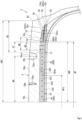
FIG. 1 is a cross-sectional view showing a part of a heavy duty pneumatic tire according to one embodiment of the present invention; -
FIG. 2 is an enlarged cross-sectional view showing a part of the tire inFIG. 1 ; and -
FIG. 3 is a schematic diagram illustrating the configuration of a reinforcing layer. - Hereinafter, the present invention will be described in detail based on preferred embodiments with appropriate reference to the drawings.
- In the present invention, a state where a tire is fitted on a standardized rim, the internal pressure of the tire is adjusted to a standardized internal pressure, and no load is applied to the tire is referred to as standardized state.
- In the present invention, unless otherwise specified, the dimensions and angles of each component of the tire are measured in the standardized state.
- The dimensions and angles of each component in a meridian cross-section of the tire, which cannot be measured in a state where the tire is fitted on the standardized rim, are measured in a cut plane of the tire obtained by cutting the tire along a plane including a rotation axis. In this measurement, the tire is set such that the distance between right and left beads is equal to the distance between the beads in the tire that is fitted on the standardized rim. The configuration of the tire that cannot be confirmed in a state where the tire is fitted on the standardized rim is confirmed in the above-described cut plane.
- The standardized rim means a rim specified in a standard on which the tire is based. The "standard rim" in the JATMA standard, the "Design Rim" in the TRA standard, and the "Measuring Rim" in the ETRTO standard are standardized rims.
- The standardized internal pressure means an internal pressure specified in the standard on which the tire is based. The "highest air pressure" in the JATMA standard, the "maximum value" recited in the "TIRE LOAD LIMITS AT VARIOUS COLD INFLATION PRESSURES" in the TRA standard, and the "INFLATION PRESSURE" in the ETRTO standard are standardized internal pressures.
- A standardized load means a load specified in the standard on which the tire is based. The "maximum load capacity" in the JATMA standard, the "maximum value" recited in the "TIRE LOAD LIMITS AT VARIOUS COLD INFLATION PRESSURES" in the TRA standard, and the "LOAD CAPACITY" in the ETRTO standard are standardized loads.
- In the present invention, the "nominal aspect ratio" is the "nominal aspect ratio" included in the "tire designation" specified in JIS D4202 "Automobile tyres-Designation and dimensions".
- In the present invention, the tread of the tire is a portion of the tire that comes into contact with a road surface. In the tire, an axially outer portion from each shoulder circumferential groove of the tread (including the shoulder circumferential groove) is a shoulder portion. In addition, a portion interposed between the shoulder portions of the tread is a center portion.
- In the present invention, the number of cross-sections of cords (the number of cords) included per 5 cm width of a tire component including aligned cords is represented as the density of cords included in this component (unit: ends/5 cm). Unless otherwise specified, the density of the cords is obtained in a cross-section of the component obtained by cutting the component along a plane perpendicular to the longitudinal direction of the cords.
-
FIG. 1 shows a part of a heavy duty pneumatic tire 2 (hereinafter also referred to simply as "tire 2") according to one embodiment of the present invention. Thetire 2 is mounted to a vehicle such as a truck and a bus. The nominal aspect ratio of thetire 2 is not greater than 65%. In other words, thetire 2 has a nominal aspect ratio of not greater than 65%. Thetire 2 is a low-flatness tire. -
FIG. 1 shows a part of a cross-section (hereinafter referred to as meridian cross-section) of thetire 2 along a plane including the rotation axis of thetire 2. InFIG. 1 , the right-left direction is the axial direction of thetire 2, and the up-down direction is the radial direction of thetire 2. The direction perpendicular to the surface of the drawing sheet ofFIG. 1 is the circumferential direction of thetire 2. An alternate long and short dash line CL represents the equator plane of thetire 2. -
FIG. 2 shows a part of the cross-section of thetire 2 shown inFIG. 1 .FIG. 2 shows atread 4 of thetire 2. InFIG. 2 , the right-left direction is the axial direction of thetire 2, and the up-down direction is the radial direction of thetire 2. The direction perpendicular to the surface of the drawing sheet ofFIG. 2 is the circumferential direction of thetire 2. - The
tire 2 is fitted onto a rim (not shown). The rim is a standardized rim. The interior of thetire 2 is filled with air to adjust the internal pressure of thetire 2. Thetire 2 fitted on the rim is also referred to as a tire-rim assembly. The tire-rim assembly includes the rim and thetire 2 fitted on the rim. - The
tire 2 includes thetread 4, a pair ofsidewalls 6, a pair ofbeads 8, a pair ofchafers 10, acarcass 12, a pair of cushion layers 14, aninner liner 16, a pair ofsteel fillers 18, and a reinforcinglayer 20. - The
tread 4 comes into contact with a road surface at an outer surface thereof. This outer surface is atread surface 22. InFIG. 1 , reference character PC indicates the point of intersection of thetread surface 22 and the equator plane CL. The point of intersection PC is the equator of thetire 2. - In
FIG. 1 , reference character PE indicates an end of thetread surface 22. A double-headed arrow WT indicates the width of thetread surface 22. The width WT of thetread surface 22 is represented as the distance in the axial direction from one end PE of thetread surface 22 to another end PE of thetread surface 22. - Although not shown, the
tread 4 can include a base portion and a cap portion located radially outward of the base portion. - In this case, each of the base portion and the cap portion is formed from a crosslinked rubber. The base portion is formed from a crosslinked rubber that has low heat generation properties. The cap portion is formed from a crosslinked rubber for which wear resistance, low temperature properties, and grip performance are taken into consideration.
- In the
tire 2, at least twocircumferential grooves 28 are formed on thetread 4. On thetread 4 of thetire 2 shown inFIG. 1 , fourcircumferential grooves 28 are formed. Thesecircumferential grooves 28 are aligned in the axial direction and extend continuously in the circumferential direction. - Among the four
circumferential grooves 28 formed on thetread 4, thecircumferential groove 28 located on each outer side in the axial direction is a shouldercircumferential groove 28s. Thecircumferential groove 28 located inward of the shouldercircumferential groove 28s in the axial direction is a middlecircumferential groove 28m. In thetire 2, the fourcircumferential grooves 28 include a pair of the middlecircumferential grooves 28m and a pair of the shouldercircumferential grooves 28s. - In the
tire 2, from the viewpoint of ensuring the stiffness of the center portion of thetread 4, the width of each middlecircumferential groove 28m is preferably narrower than the width of each shouldercircumferential groove 28s. - In the
tire 2, the width of the middlecircumferential groove 28m is preferably not less than 5% and not greater than 35% of the width of the shouldercircumferential groove 28s. - In the
tire 2, the width of the middlecircumferential groove 28m is preferably not greater than 2% of the width WT of thetread surface 22. The lower limit of the width of the middlecircumferential groove 28m is, for example, 1 mm. - The width of each
circumferential groove 28 is represented as the shortest distance between one edge and another edge of thecircumferential groove 28. - In
FIG. 2 , a double-headed arrow DGm indicates the depth of the middlecircumferential groove 28m. A double-headed arrow DGs indicates the depth of the shouldercircumferential groove 28s. - In the
tire 2, from the viewpoint of ensuring the stiffness of the center portion of thetread 4, the depth DGm of the middlecircumferential groove 28m is preferably equal to the depth DGs of the shouldercircumferential groove 28s or shallower than the depth DGs of the shouldercircumferential groove 28s. The depth DGm of the middlecircumferential groove 28m is more preferably shallower than the depth DGs of the shouldercircumferential groove 28s. - In the
tire 2, the depth DGm of the middlecircumferential groove 28m is preferably not less than 60% and not greater than 100% of the depth DGs of the shouldercircumferential groove 28s. - The depth DGs of the shoulder
circumferential groove 28s is, for example, not less than 10 mm and not greater than 25 mm. - The depth of each
circumferential groove 28 is represented as the distance from thetread surface 22 to the bottom of thecircumferential groove 28. - In
FIG. 2 , a double-headed arrow WA indicates the distance from the equator PC of thetire 2 to the shouldercircumferential groove 28s. The distance WA is the distance in the axial direction between the equator PC and the bottom of the shouldercircumferential groove 28s. - In the
tire 2, the distance WA from the equator PC to the shouldercircumferential groove 28s is preferably not less than 45% and not greater than 70% of a distance HWT in the axial direction from the equator PC to the end PE of thetread surface 22. - This case is suitable for improving the uneven wear resistance of the
tread 4. - The opening of the shoulder
circumferential groove 28s during inflation increases as the distance from the shouldercircumferential groove 28s to the equator PC of thetire 2 increases. Therefore, if the distance WA exceeds 70% of the distance HWT, the shouldercircumferential groove 28s is excessively separated from the equator PC, so that the opening of the shouldercircumferential groove 28s increases, and a dimensional change around the shouldercircumferential groove 28s increases. As a result, uneven wear is likely to occur. If the distance WA exceeds 70% of the distance HWT, the width of ashoulder land portion 30s becomes relatively narrower, and the ground-contact pressure at this portion locally increases. Therefore, from this point of view, uneven wear is also likely to occur. - On the other hand, if the distance WA is less than 45% of the distance HWT, the width of a
center land portion 30c described later tends to become narrower, and it is difficult to ensure sufficient stiffness of the center portion of thetread 4. - The distance HWT in the axial direction from the equator PC of the
tire 2 to the end PE of thetread surface 22 is half the width WT of thetread surface 22. - As described above, at least two
circumferential grooves 28 are formed on thetread 4 of thetire 2. Accordingly, at least threeland portions 30 are formed in thetread 4. On thetread 4 of thetire 2 shown inFIG. 1 , fourcircumferential grooves 28 are formed, so that fiveland portions 30 are formed therein. Theseland portions 30 are aligned in the axial direction and extend continuously in the circumferential direction. - In the
tire 2, from the viewpoint of increasing the stiffness of the center portion of thetread 4, at least one land portion of the at least threeland portions 30 is a land portion including the equator PC of thetire 2. - Among the five
land portions 30 formed in thetread 4, theland portion 30 including the equator PC of thetire 2 is thecenter land portion 30c. Theland portion 30 located on each outer side in the axial direction is theshoulder land portion 30s. Theshoulder land portion 30s is located outward of the shouldercircumferential groove 28s in the axial direction and includes the end PE of thetread surface 22. Theland portion 30 located between thecenter land portion 30c and theshoulder land portion 30s in the axial direction is amiddle land portion 30m. The shouldercircumferential groove 28s is present between themiddle land portion 30m and theshoulder land portion 30s. The middlecircumferential groove 28m is present between themiddle land portion 30m and thecenter land portion 30c. In thetire 2 shown inFIGS. 1 and2 , the fiveland portions 30 include thecenter land portion 30c, a pair of themiddle land portions 30m, and a pair of theshoulder land portions 30s. - In the case where the
tire 2 includes threeland portions 30, theland portions 30 include acenter land portion 30c and a pair ofshoulder land portions 30s. - In the case where the
tire 2 includes six ormore land portions 30, theland portions 30 include acenter land portion 30c, a pair ofshoulder land portions 30s, and three or moremiddle land portions 30m. - The
center land portion 30c is a land portion including the equator PC of thetire 2. In thetire 2 including thecenter land portion 30c, the stiffness of the center portion of thetread 4 is high. In thetire 2, a dimensional change is less likely to occur at the center portion of thetread 4 than in a tire in which a circumferential groove is located on the equator plane CL thereof, and thetire 2 is suitable as an LRR tire. - In
FIGS. 1 and2 , a double-headed arrow WC indicates the width of thecenter land portion 30c. A double-headed arrow WM indicates the width of themiddle land portion 30m. A double-headed arrow WS indicates the width of theshoulder land portion 30s. - In the
tire 2, the width WC of thecenter land portion 30c is preferably not less than 5% and preferably not greater than 65% of the width WT of thetread surface 22. - If the width WC is less than 5% of the width WT, sufficient stiffness of the center portion of the
tread 4 cannot be ensured. - If the width WC exceeds 65% of the width WT, the position of the shoulder
circumferential groove 28s is greatly separated from the equator PC of thetire 2. Therefore, the shouldercircumferential groove 28s becomes easier to open, and a dimensional change around the shouldercircumferential groove 28s becomes larger. As a result, uneven wear is likely to occur. In addition, the width WS of theshoulder land portion 30s becomes relatively narrower, and the ground-contact pressure at this portion locally increases. Therefore, from this point of view, uneven wear is also likely to occur. - The width WM of the
middle land portion 30m is not less than 5% and not greater than 18% of the width WT of thetread surface 22. The width WS of theshoulder land portion 30s is not less than 7.5% and not greater than 25% of the width WT of thetread surface 22. - The width of each
land portion 30 is represented as the width in the axial direction of the top surface of theland portion 30 that forms a part of thetread surface 22. Therefore, the width WC of thecenter land portion 30c is represented as the distance in the axial direction from one end to another end of the top surface of thecenter land portion 30c (distance in the axial direction between the inner edges of the middlecircumferential grooves 28m). The width WM of themiddle land portion 30m is represented as the distance in the axial direction from the inner end of the top surface of themiddle land portion 30m (outer edge of the middlecircumferential groove 28m) to the outer end of this top surface (inner edge of the shouldercircumferential groove 28s). The width WS in the axial direction of theshoulder land portion 30s is represented as the distance in the axial direction from the inner end of the top surface of theshoulder land portion 30s (outer edge of the shouldercircumferential groove 28s) to the outer end of this top surface (end PE of thetread surface 22 in the tire 2). - The width WC of the
center land portion 30c is more preferably not less than 12% of the width WT of thetread surface 22. In this case, since the width WC of thecenter land portion 30c is wide, the stiffness of the center portion of thetread 4 in thetire 2 becomes higher. Therefore, thetire 2 is suitable as a tire including the reinforcinglayer 20 having a configuration described later. - The width WC of the
center land portion 30c is more preferably not greater than 50% of the width WT of thetread surface 22. - Each
sidewall 6 is connected to an end of thetread 4. Thesidewall 6 extends radially inward from the end of thetread 4. Thesidewall 6 is formed from a crosslinked rubber. - Each
bead 8 is located radially inward of thesidewall 6. Thebead 8 includes acore 32 and an apex 34. - The
core 32 extends in the circumferential direction. Thecore 32 includes a wound wire made of steel. Thecore 32 has a substantially hexagonal cross-sectional shape. - The apex 34 is located radially outward of the
core 32. The apex 34 includes aninner apex 34u and an outer apex 34s. Theinner apex 34u extends outward in the radial direction from thecore 32. The outer apex 34s is located radially outward of theinner apex 34u. Theinner apex 34u is formed from a hard crosslinked rubber. The outer apex 34s is formed from a crosslinked rubber that is more flexible than theinner apex 34u. The outer apex 34s is more flexible than theinner apex 34u. - Each
chafer 10 is located axially outward of thebead 8. Thechafer 10 is located radially inward of thesidewall 6. Thechafer 10 comes into contact with a rim (not shown). Thechafer 10 is formed from a crosslinked rubber for which wear resistance is taken into consideration. - The
carcass 12 is located inward of thetread 4, thesidewalls 6, and thechafers 10. Thecarcass 12 includes at least onecarcass ply 36. Thecarcass 12 of thetire 2 is composed of onecarcass ply 36. The carcass ply 36 is turned up around each core 32 from the inner side toward the outer side in the axial direction. - The carcass ply 36 includes a large number of carcass cords aligned with each other, which are not shown. These carcass cords are covered with a topping rubber. Each carcass cord intersects the equator plane CL. In the
tire 2, an angle of the carcass cord with respect to the equator plane CL is not less than 70° and not greater than 90°. Thecarcass 12 has a radial structure. In thetire 2, a steel cord is used as each carcass cord. - Each
cushion layer 14 is located between the reinforcinglayer 20 and thecarcass 12 at an end of the reinforcinglayer 20. Thecushion layer 14 is formed from a flexible crosslinked rubber. - The
inner liner 16 is located inward of thecarcass 12. Theinner liner 16 forms an inner surface of thetire 2. Theinner liner 16 is formed from a crosslinked rubber that has an excellent air blocking property. Theinner liner 16 maintains the internal pressure of thetire 2. - Each
steel filler 18 is located in a portion at thebead 8. Thesteel filler 18 is turned up around the core 32 from the inner side toward the outer side in the axial direction along thecarcass ply 36. - The
steel filler 18 includes a large number of filler cords aligned with each other, which are not shown. In thesteel filler 18, the filler cords are covered with a topping rubber. In thetire 2, a steel cord is used as each filler cord. - As shown in
FIGS. 1 and2 , the reinforcinglayer 20 is located inward of thetread 4 in the radial direction. The reinforcinglayer 20 is located between thecarcass 12 and thetread 4. The reinforcinglayer 20 includes abelt 38 and aband 40. - The
belt 38 includes a plurality of belt plies 42 aligned in the radial direction. Each belt ply 42 is placed such that both ends thereof are opposed to each other across the equator plane CL. Thebelt 38 of thetire 2 includes four belt plies 42. The four belt plies 42 include a first belt ply 42A located on the inner side in the radial direction, asecond belt ply 42B located outward of the first belt ply 42A, a third belt ply 42C located outward of thesecond belt ply 42B, and afourth belt ply 42D located outward of thethird belt ply 42C. - In the
tire 2, thesecond belt ply 42B has a widest width in the axial direction, and the fourth belt ply 42D has a narrowest width in the axial direction. The first belt ply 42A and the third belt ply 42C have the same width in the axial direction, or the width in the axial direction of thefirst belt ply 42A is wider than the width in the axial direction of thethird belt ply 42C. - An
end 38e of thebelt 38 of thetire 2 is represented as an end of the belt ply 42 having a widest width in the axial direction among the plurality of belt plies 42 included in thebelt 38. In thetire 2, as described above, among the four belt plies 42 included in thebelt 38, thesecond belt ply 42B has a widest width in the axial direction. Theend 38e of thebelt 38 of thetire 2 is represented as an end 42Be of thesecond belt ply 42B having a widest width in the axial direction. Theend 38e of thebelt 38 is also anend 20e of the reinforcinglayer 20. - As shown in
FIGS. 1 and2 , in thetire 2, each of ends 42e of the first belt ply 42A to thefourth belt ply 42D is located outward of the shouldercircumferential groove 28s in the axial direction. - In the
tire 2, from the viewpoint of ensuring the stiffness of thetread 4 portion, the ratio of the width in the axial direction of each belt ply 42 to the width WT of thetread surface 22 is preferably in the following range. - The ratio of the width in the axial direction of the first belt ply 42A to the width WT of the
tread surface 22 is preferably not less than 0.80 and preferably not greater than 0.90. - The ratio of the width in the axial direction of the second belt ply 42B to the width WT of the
tread surface 22 is preferably not less than 0.85 and preferably not greater than 0.95. - The ratio of the width in the axial direction of the third belt ply 42C to the width WT of the
tread surface 22 is preferably not less than 0.80 and preferably not greater than 0.90. - The ratio of the width in the axial direction of the
fourth belt ply 42D to the width WT of thetread surface 22 is preferably not less than 0.55 and preferably not greater than 0.65. - The width of each belt ply 42 is represented as the distance in the axial direction from one
end 42e to anotherend 42e of thebelt ply 42. -
FIG. 3 shows the configuration of the reinforcinglayer 20. - In
FIG. 3 , the right-left direction is the axial direction of thetire 2, and the up-down direction is the circumferential direction of thetire 2. The direction perpendicular to the surface of the drawing sheet ofFIG. 3 is the radial direction of thetire 2. The front side of the drawing sheet ofFIG. 3 is the outer side in the radial direction, and the back side of this drawing sheet is the inner side in the radial direction. - As shown in
FIG. 3 , in thetire 2, each belt ply 42 included in thebelt 38 includes a large number ofbelt cords 44 aligned with each other. InFIG. 3 , thebelt cords 44 are represented by solid lines for convenience of description, but thebelt cords 44 are covered with a toppingrubber 46. Thebelt cords 44 of thetire 2 are steel cords. - In the
tire 2, the density of the belt cords 44 (the number of cross-sections of cords per unit width) in each belt ply 42 is preferably not less than 15 ends/5 cm and not greater than 30 ends/5 cm. - In each belt ply 42, the
belt cords 44 are inclined with respect to the circumferential direction. - The direction of inclination of the
belt cords 44 included in the first belt ply 42A with respect to the circumferential direction (hereinafter referred to as inclination direction of the first belt ply 42A) is the same as the direction of inclination of thebelt cords 44 included in thesecond belt ply 42B with respect to the circumferential direction (hereinafter referred to as inclination direction of the second belt ply 42B). - The inclination direction of the
second belt ply 42B is opposite to the direction of inclination of thebelt cords 44 included in thethird belt ply 42C with respect to the circumferential direction (hereinafter referred to as inclination direction of thethird belt ply 42C). - The inclination direction of the third belt ply 42C is the same as the direction of inclination of the
belt cords 44 included in thefourth belt ply 42D with respect to the circumferential direction (hereinafter referred to as inclination direction of thefourth belt ply 42D). - The inclination direction of the first belt ply 42A may be opposite to the inclination direction of the
second belt ply 42B, and the inclination direction of thefourth belt ply 42D may be opposite to the inclination direction of thethird belt ply 42C. From the viewpoint of ensuring a stable ground-contact shape, the inclination direction of thesecond belt ply 42B is preferably opposite to the inclination direction of thethird belt ply 42C. - In
FIG. 3 , an angle θ1 is an inclination angle of thebelt cords 44 included in the first belt ply 42A with respect to the equator plane CL (hereinafter referred to as first inclination angle θ1). An angle θ2 is an inclination angle of thebelt cords 44 included in thesecond belt ply 42B with respect to the equator plane CL (hereinafter referred to as second inclination angle θ2). An angle θ3 is an inclination angle of thebelt cords 44 included in thethird belt ply 42C with respect to the equator plane CL (hereinafter referred to as third inclination angle θ3). An angle θ4 is an inclination angle of thebelt cords 44 included in thefourth belt ply 42D with respect to the equator plane CL (hereinafter referred to as fourth inclination angle θ4). - In the
tire 2, the first inclination angle 01, the second inclination angle θ2, the third inclination angle θ3, and the fourth inclination angle θ4 are preferably not less than 10° and preferably not greater than 60°. From the viewpoint of effectively restricting the movement of thetire 2 and ensuring a stable ground-contact shape, the first inclination angle θ1 is preferably not less than 40° and preferably not greater than 60°. The second inclination angle θ2 is preferably not less than 10° and preferably not greater than 20°. The third inclination angle θ3 is preferably not less than 10° and preferably not greater than 20°. The fourth inclination angle θ4 is preferably not less than 10° and preferably not greater than 60°. - The
band 40 includes afull band 48 and a pair ofedge bands 50. - As shown in
FIGS. 1 to 3 , thefull band 48 hasends 48e opposed to each other across the equator plane CL. The pair ofedge bands 50 are placed so as to be spaced apart from each other in the axial direction with the equator plane CL therebetween. In thetire 2, thefourth belt ply 42D which forms a part of thebelt 38 is located between the right and leftedge bands 50. - Each
edge band 50 is located between thetread 4 and thefull band 48. Theedge band 50 is located outward of theend 48e of thefull band 48 in the radial direction. An inner end 50ue of theedge band 50 is located inward of theend 48e of thefull band 48 in the axial direction. An outer end 50se of theedge band 50 is located outward of theend 48e of thefull band 48 in the axial direction. The position of the outer end 50se of theedge band 50 may coincide with the position of theend 48e of thefull band 48 in the axial direction. Theedge band 50 overlaps theend 48e of thefull band 48 in the radial direction. - As shown in
FIGS. 2 and3 , thefull band 48 includes twoend regions 48B each located on the outer side in the axial direction, and acentral region 48A interposed between the twoend regions 48B. Thecentral region 48A is located axially inward of eachend region 48B. - In the
tire 2, both end portions 48Ae of thecentral region 48A are located axially inward of the shouldercircumferential grooves 28s. Both end portions 48Ae of thecentral region 48A do not overlap the shouldercircumferential grooves 28s in the radial direction. - If each end portion 48Ae overlaps the shoulder
circumferential groove 28s in the radial direction, the stiffness difference of the lower side (radially inner side) of the shouldercircumferential groove 28s increases, so that bending of the groove bottom is promoted and strain is likely to accumulate at the groove bottom. Therefore, there is a concern about occurrence of tread groove cracking (TGC) or a decrease in the durability of thetire 2. In addition, due to the promotion of bending of the groove bottom of the shouldercircumferential groove 28s, theshoulder land portion 30s becomes easier to move, and track wear is more likely to occur on the axially inner side of theshoulder land portion 30s. Furthermore, if each end portion 48Ae is located axially outward of the shouldercircumferential groove 28s, a dimensional change of the shoulder portion of thetread 4 cannot be sufficiently suppressed. - Furthermore, it is preferable that both end portions 48Ae of the
central region 48A do not overlap the middlecircumferential grooves 28m in the radial direction. If each end portion 48Ae overlaps the middlecircumferential groove 28m in the radial direction, strain is likely to accumulate at the groove bottom of the middlecircumferential groove 28m, and in this case as well, there is a concern about occurrence of TGC or a decrease in the durability of thetire 2. - It is preferable that both end portions 48Ae of the
central region 48A are located between the middlecircumferential grooves 28m and the shouldercircumferential grooves 28s in the axial direction. - In the
tire 2, an axially outer end portion 48Be of eachend region 48B is located axially outward of the shouldercircumferential groove 28s. The axially outer end portion 48Be of eachend region 48B does not overlap the shouldercircumferential groove 28s in the radial direction. - The axially outer end portion 48Be of each
end region 48B is also theend 48e of thefull band 48. - In
FIG. 2 , a double-headed arrow WF indicates the width of thefull band 48. The width WF of thefull band 48 is represented as the distance in the axial direction from oneend 48e to anotherend 48e of thefull band 48. A double-headed arrow WFC indicates the width of thecentral region 48A. The width WFC of thecentral region 48A is represented as the distance in the axial direction from one end 48Ae to another end 48Ae of thecentral region 48A. - The width WFC of the
central region 48A is preferably not less than 20% of the width WT of thetread surface 22. If the width WFC is less than 20% of the width WT, a dimensional change of the center portion of thetread 4 is likely to be excessively suppressed. - As shown in
FIG. 3 , thefull band 48 and the pair ofedge bands 50 included in theband 40 each include a helicallywound band cord 52. InFIG. 3 , eachband cord 52 is represented by a solid line for convenience of description, but eachband cord 52 is covered with a toppingrubber 54. - In the
tire 2, eachband cord 52 is a steel cord or a cord formed from an organic fiber (hereinafter referred to as organic fiber cord). In the case where an organic fiber cord is used as eachband cord 52, examples of the organic fiber include nylon fibers, polyester fibers, rayon fibers, and aramid fibers. From the viewpoint of stiffness, eachband cord 52 is preferably a steel cord. - In the
tire 2, as theband cord 52 of thefull band 48 and theband cord 52 of eachedge band 50, the same cord may be used or different cords may be used. Theband cords 52 used for thefull band 48 and eachedge band 50 are determined according to the specifications of thetire 2. - As described above, the
full band 48 includes the helicallywound band cord 52. Thefull band 48 has a jointless structure. In thefull band 48, an angle of theband cord 52 with respect to the circumferential direction is preferably not greater than 5° and more preferably not greater than 2°. Theband cord 52 of thefull band 48 extends substantially in the circumferential direction. - In the
full band 48, the same band cord may be continuously wound in thecentral region 48A and eachend region 48B, or different band cords may be wound in thecentral region 48A and eachend region 48B. - As described above, each
edge band 50 includes the helicallywound band cord 52. Theedge band 50 has a jointless structure. In theedge band 50, an angle of theband cord 52 with respect to the circumferential direction is preferably not greater than 5° and more preferably not greater than 2°. Theband cord 52 of theedge band 50 extends substantially in the circumferential direction. - In the
tire 2, the density of theband cord 52 in thecentral region 48A (hereinafter also referred to as band central density) is lower than the density of theband cord 52 in eachend region 48B (hereinafter also referred to as band end density). Specifically, in thefull band 48 of thetire 2, the number of cross-sections of theband cord 52 per 5 cm width is smaller in thecentral region 48A than in eachend region 48B. - In the
tire 2, the band end density is preferably not less than 1.2 times and preferably not greater than 2.0 times the band central density. This case is suitable for reducing the difference in dimensional change between each shoulder portion of thetread 4 and the center portion of thetread 4. - If the band end density is less than 1.2 times the band central density, the force to constrain the center portion by the
full band 48 is high in a tire in which the stiffness of a center portion is high such as thetire 2. Therefore, although theedge bands 50 are included, a dimensional change is more likely to occur at each shoulder portion than at the center portion, so that it is difficult to make the ground-contact pressure of the tire uniform. - On the other hand, if the band end density exceeds 2.0 times the band central density, even in a tire in which the stiffness of a center portion is high such as the
tire 2, the stiffness difference between the center portion and each shoulder portion of the tread is large, so that a portion at each shouldercircumferential groove 28s becomes easier to bend. If the portion at each shouldercircumferential groove 28s becomes easier to bend, strain is likely to accumulate at the shouldercircumferential groove 28s, and the accumulated strain becomes a cause of TGC or a factor of a decrease in durability. - In addition, if the portion at each shoulder
circumferential groove 28s becomes easier to bend, theshoulder land portion 30s becomes easier to move, and as a result, an axially inner portion of theshoulder land portion 30s becomes easily worn. - In the
full band 48, the band central density is preferably not less than 10 ends/5 cm and not greater than 30 ends/5 cm. - In each
edge band 50, the density of theband cord 52 is preferably equal to or higher than the band end density of thefull band 48. - In this case, the
edge band 50 is suitable for suppressing a dimensional change of the shoulder portion of thetread 4 by the effect of suppressing a break of theband cord 52 of thefull band 48 and the constraining force applied to thetread 4 by theedge band 50. - In each
edge band 50, the density of theband cord 52 is preferably not less than 20 ends/5 cm and not greater than 35 ends/5 cm. The density of theband cord 52 of theedge band 50 is represented as the number of cross-sections of theband cord 52 included per 5 cm width of theedge band 50 in a cross-section of theedge band 50 along a plane perpendicular to the direction in which theband cord 52 extends. - In the
tire 2, each of the end 42Be of the second belt ply 42B and an end 42Ce of the third belt ply 42C is covered with arubber layer 56. Between the end 42Be of the second belt ply 42B and the end 42Ce of thethird belt ply 42C covered with therubber layer 56, tworubber layers 56 are further placed. In thetire 2, anedge member 58 including fourrubber layers 56 in total is formed between the end 42Be of the second belt ply 42B and the end 42Ce of thethird belt ply 42C. - The
edge member 58 is formed from a crosslinked rubber. Theedge member 58 contributes to maintaining the interval between the end 42Be of the second belt ply 42B and the end 42Ce of thethird belt ply 42C. In thetire 2, a change in the positional relationship between the end 42Be of the second belt ply 42B and the end 42Ce of thethird belt ply 42C due to running is suppressed. Theedge member 58 is a part of the reinforcinglayer 20. The reinforcinglayer 20 of thetire 2 includes a pair ofedge members 58 in addition to thebelt 38 and theband 40. - As described above, the
full band 48 has theends 48e opposed to each other across the equator plane CL. Thefull band 48 extends in the axial direction from the equator plane CL to eachend 48e. Eachend 48e of thefull band 48 is located outward of the shouldercircumferential groove 28s in the axial direction. Thefull band 48 is located inward of each shouldercircumferential groove 28s in the radial direction. - Although the
tire 2 has low flatness, thefull band 48 effectively suppresses deformation around each shouldercircumferential groove 28s. A change in the shape of thetire 2, e.g., the contour of the carcass 12 (also referred to as case line), is suppressed, so that a change in ground-contact shape is suppressed. - In the
tire 2, as described above, thefull band 48 includes thecentral region 48A in which the density of theband cord 52 is relatively low, and theend regions 48B in each of which the density of theband cord 52 is relatively high. Furthermore, the pair ofedge bands 50 spaced apart from each other in the axial direction with the equator plane CL therebetween are also included. Therefore, in thetread 4, the difference between the dimensional change of the center portion and the dimensional change of each shoulder portion can be reduced, so that occurrence of uneven wear can be suppressed. - Furthermore, in the
tire 2, eachedge band 50 is located outward of theend 48e of thefull band 48 in the radial direction. Theedge band 50 constrains theend 48e of thefull band 48. Fluctuation of the tension of theband cord 52 included in thefull band 48 is suppressed, so that occurrence of a break of theband cord 52 due to this tension fluctuation is suppressed. Thefull band 48 of thetire 2 can stably exhibit the function of suppressing a dimensional change. Theedge band 50 is narrower than thefull band 48. Therefore, tension fluctuation as in thefull band 48 is less likely to occur in theband cord 52 of theedge band 50. A break is less likely to occur in theband cord 52 of theedge band 50. - In
FIG. 2 , a double-headed arrow WE indicates the width of theedge band 50. The width of theedge band 50 is represented as the distance in the axial direction from the inner end 50ue to the outer end 50se of theedge band 50. In thetire 2, the width WE of theedge band 50 is preferably not less than 15% and not greater than 40% of a half (also referred to as 1/2 width) HWF of the width WF of thefull band 48. In this case, theedge band 50 can exhibit the effect caused by providing an edge band, without suppressing a dimensional change of the center portion of thetread 4. - If the width WE of the
edge band 50 is less than 15% of the 1/2 width HWF of thefull band 48, the force to suppress a dimensional change of the shoulder portion by theedge band 50 becomes weaker. Therefore, theedge band 50 cannot sufficiently exhibit its effect in some cases. On the other hand, if the width WE of theedge band 50 exceeds 40% of the 1/2 width HWF of thefull band 48, the effect of suppressing a dimensional change tends to be exhibited for not only each shoulder portion of thetread 4 but also the center portion. Therefore, the difference in dimensional change between each shoulder portion and the center portion is not reduced, so that it is difficult to improve uneven wear resistance. - In the
tire 2, a dimensional change of thetire 2 itself during running is suppressed by thefull band 48 and eachedge band 50. Furthermore, the difference between the dimensional change of the center portion and the dimensional change of each shoulder portion in thetread 4 is reduced to be small. In thetire 2, occurrence of uneven wear, which is a concern in conventional tires, is suppressed. - In
FIG. 2 , a double-headed arrow SF indicates the distance in the axial direction from the shouldercircumferential groove 28s, specifically, the outer edge of the shouldercircumferential groove 28s, to theend 48e of thefull band 48. - In the
tire 2, the distance SF in the axial direction from the shouldercircumferential groove 28s to theend 48e of thefull band 48 is preferably not less than 10% of the width WS in the axial direction of theshoulder land portion 30s. - In this case, the
end 48e of thefull band 48 is located at an appropriate interval from the bottom of the shouldercircumferential groove 28s. In thetire 2, occurrence of damage starting from the bottom of the shouldercircumferential groove 28s is suppressed. In addition, since the width of thefull band 48 is ensured, thefull band 48 contributes to suppression of a dimensional change of thetread 4. From this viewpoint, the distance SF is more preferably not less than 15% of the width WS. - In the
tire 2, the distance SF in the axial direction from the shouldercircumferential groove 28s to theend 48e of thefull band 48 is preferably not greater than 50% of the width WS in the axial direction of theshoulder land portion 30s. - In this case, the
end 48e of thefull band 48 is located away from the end portion of thetread 4 which moves actively during running, so that fluctuation of the tension of theband cord 52 included in thefull band 48 is suppressed. In thetire 2, occurrence of a break of theband cord 52 included in thefull band 48 is suppressed. Thefull band 48 of thetire 2 contributes to suppression of a dimensional change. From this viewpoint, the distance SF is more preferably not greater than 35% of the width WS and further preferably not greater than 25% of the width WS. - In
FIG. 2 , a double-headed arrow WD indicates the distance in the axial direction from theend 48e of thefull band 48 to the inner end 50ue of theedge band 50. - The distance WD in the axial direction is preferably not less than 10 mm. Accordingly, the
edge band 50 effectively constrains theend 48e of thefull band 48. Fluctuation of the tension of theband cord 52 included in thefull band 48 is suppressed, so that occurrence of a break of theband cord 52 due to this tension fluctuation is suppressed. Thefull band 48 of thetire 2 can more stably exhibit the function of suppressing a shape change. From this viewpoint, the distance WD in the axial direction is more preferably not less than 20 mm. - In the
tire 2, the position of the inner end 50ue of theedge band 50 is determined as appropriate in consideration of involvement in occurrence of damage starting from the bottom of the shouldercircumferential groove 28s. Therefore, a preferable upper limit of the distance WD in the axial direction is not set. - In the
tire 2, in the axial direction, eachend 48e of thefull band 48 is located inward of theend 38e of thebelt 38, and thebelt 38 is wider than thefull band 48. In this case, thebelt 38 constrains eachend 48e of thefull band 48. Thebelt 38 contributes to suppression of fluctuation of the tension of theband cord 52 included in thefull band 48. If fluctuation of the tension of theband cord 52 is suppressed, occurrence of a break of theband cord 52 is suppressed, so that thefull band 48 can stably exhibit the function of suppressing a dimensional change. From this viewpoint, it is preferable that eachend 48e of thefull band 48 is located inward of theend 38e of thebelt 38 in the axial direction. - A force acts on the
full band 48 of thetire 2 so as to spread from the inner side toward the outer side in the radial direction. This force causes tension in theband cord 52 included in thefull band 48. In thetire 2, thesecond belt ply 42B is located radially inward of thefull band 48. - In the
tire 2, thesecond belt ply 42B reduces the force acting on thefull band 48, so that the tension of theband cord 52 included in thefull band 48 is appropriately maintained. Thesecond belt ply 42B contributes to suppression of fluctuation of the tension of theband cord 52. Since thesecond belt ply 42B is wider than thefull band 48, fluctuation of the tension of theband cord 52 is effectively suppressed. In thetire 2, a break is less likely to occur in theband cord 52 of thefull band 48. Thefull band 48 can stably exhibit the function of suppressing a shape change. From this viewpoint, it is preferable that among the plurality of belt plies 42 included in thebelt 38, at least onebelt ply 42 is located inward of thefull band 48 in the radial direction. It is more preferable that the at least one belt ply 42 located inward of thefull band 48 has a width wider than the width WF of thefull band 48. - In the
tire 2, from the viewpoint of suppressing fluctuation of the tension of theband cord 52 of thefull band 48 and making it less likely to cause a break of theband cord 52 due to tension fluctuation, it is more preferable that thesecond belt ply 42B which is wider than thefull band 48 is located inward of thefull band 48 in the radial direction and thethird belt ply 42C which is wider than thefull band 48 is located outward of thefull band 48 in the radial direction. - Furthermore, from the same viewpoint, in the
tire 2, it is further preferable that the first belt ply 42A, thesecond belt ply 42B, and the third belt ply 42C have a width wider than the width WF of thefull band 48, the first belt ply 42A and thesecond belt ply 42B are located inward of thefull band 48 in the radial direction, the third belt ply 42C is located outward of thefull band 48 in the radial direction, and the pair ofedge bands 50 are each located outward of thethird belt ply 42C in the radial direction. - In particular, from the same viewpoint, in the
tire 2, it is particularly preferable that the plurality of belt plies 42 included in thebelt 38 include the first belt ply 42A located on the inner side in the radial direction, thesecond belt ply 42B located outward of the first belt ply 42A in the radial direction, and the third belt ply 42C located outward of the second belt ply 42B in the radial direction, the first belt ply 42A, thesecond belt ply 42B, and the third belt ply 42C have a width wider than the width WF of thefull band 48, the first belt ply 42A and thesecond belt ply 42B are located inward of thefull band 48 in the radial direction, the third belt ply 42C is located outward of thefull band 48 in the radial direction, and eachedge band 50 located outward of thefull band 48 overlaps theend 48e of thefull band 48 through thethird belt ply 42C in the radial direction. - As is obvious from the above description, according to the present invention, the heavy duty
pneumatic tire 2 having good uneven wear resistance is obtained. The present invention exhibits a remarkable effect in the heavy dutypneumatic tire 2 having a nominal aspect ratio of not greater than 65% and having high stiffness of the center portion of the tread. - The above-described technology for reducing the difference between the dimensional change of the center portion and the dimensional change of each shoulder portion and achieving improvement of uneven wear resistance can be applied to various tires.
Claims (14)
- A heavy duty pneumatic tire (2) having a nominal aspect ratio of not greater than 65%, the heavy duty pneumatic tire (2) comprising:a tread (4) configured to come into contact with a road surface; anda reinforcing layer (20) located inward of the tread (4) in a radial direction, whereinat least two circumferential grooves (28) are formed on the tread (4) to form at least three land portions (30) aligned in an axial direction,of the at least two circumferential grooves (28), the circumferential groove (28) located on each outer side in the axial direction is a shoulder circumferential groove (28s),the land portion (30) located outward of the shoulder circumferential groove (28s) in the axial direction is a shoulder land portion (30s),one of the at least three land portions (30) is a land portion (30c) including an equator (PC) of the tire (2),the reinforcing layer (20) includes a belt (38) including a large number of belt cords (44) aligned with each other, and a band (40) including a helically wound band cord (52),the belt (38) includes a plurality of belt plies (42) aligned in the radial direction,the band (40) includes a full band (48) having ends (48e) opposed to each other across an equator plane (CL), and a pair of edge bands (50) located outward of the ends (48e) of the full band (48) in the radial direction,the full band (48) includes two end regions (48B) each located on the outer side in the axial direction, and a central region (48A) interposed between the two end regions (48B),a density of the band cord (52) in the central region (48A) is lower than a density of the band cord (52) in each of the end regions (48B),each end (48e) of the full band (48) is located outward of the shoulder circumferential groove (28s) in the axial direction, andan inner end (50ue) of each of the edge bands (50) is located outward of the shoulder circumferential groove (28s) in the axial direction.
- The heavy duty pneumatic tire (2) according to claim 1, whereina width (WFC) of the central region (48A) is not less than 20% of a width (WT) of a tread surface (22), andeach end (48Ae) of the central region (48A) is located inward of the shoulder circumferential groove (28s) in the axial direction.
- The heavy duty pneumatic tire (2) according to claim 1 or 2, wherein the density of the band cord (52) in each of the end regions (48B) is not less than 1.2 times and not greater than 2.0 times the density of the band cord (52) in the central region (48A).
- The heavy duty pneumatic tire (2) according to any one of claims 1 to 3, wherein a distance (WA) from the equator (PC) of the tire (2) to the shoulder circumferential groove (28s) is not less than 45% and not greater than 70% of a distance (HWT) from the equator (PC) of the tire (2) to an end (PE) of the tread surface (22).
- The heavy duty pneumatic tire (2) according to any one of claims 1 to 4,
wherein a width (WC) of the land portion (30c) including the equator (PC) of the tire (2) is not less than 5% and not greater than 65% of the width (WT) of the tread surface (22). - The heavy duty pneumatic tire (2) according to claim 5, wherein the width (WC) of the land portion (30c) including the equator (PC) of the tire (2) is not less than 12% of the width (WT) of the tread surface (22).
- The heavy duty pneumatic tire (2) according to any one of claims 1 to 6,
wherein a density of the band cord (52) of each of the edge bands (50) is higher than or equal to the density of the band cord (52) in each of the end regions (48B) of the full band (48). - The heavy duty pneumatic tire (2) according to any one of claims 1 to 7,
wherein a width (WE) of each of the edge bands (50) is not less than 15% and not greater than 40% of a distance from the equator (PC) of the tire (2) to the end (48e) of the full band (48). - The heavy duty pneumatic tire (2) according to any one of claims 1 to 8,
whereinat least three circumferential grooves (28) are formed on the tread (4), anda width of at least one circumferential groove (28m) among the circumferential grooves (28) formed inward of the shoulder circumferential groove (28s) in the axial direction is narrower than a width of the shoulder circumferential groove (28s). - The heavy duty pneumatic tire (2) according to any one of claims 1 to 9, whereinat least three circumferential grooves (28) are formed on the tread (4), anda depth (DGm) of at least one circumferential groove (28m) among the circumferential grooves (28) formed inward of the shoulder circumferential groove (28s) in the axial direction is shallower than a depth (DGs) of the shoulder circumferential groove (28s).
- The heavy duty pneumatic tire (2) according to any one of claims 1 to 10,
wherein a distance (SF) in the axial direction from the shoulder circumferential groove (28s) to the end (48e) of the full band (48) is not less than 10% and not greater than 50% of a width (WS) of the shoulder land portion (30s). - The heavy duty pneumatic tire (2) according to any one of claims 1 to 11, wherein a distance (WD) in the axial direction from each end (48e) of the full band (48) to the inner end (50ue) of each of the edge bands (50) is not less than 10 mm.
- The heavy duty pneumatic tire (2) according to any one of claims 1 to 12,
wherein each end (48e) of the full band (48) is located inward of an end (38e) of the belt (38) in the axial direction. - The heavy duty pneumatic tire (2) according to any one of claims 1 to 13, wherein at least one belt ply (42) among the plurality of belt plies (42) is located inward of the full band (48) in the radial direction.
Applications Claiming Priority (1)
| Application Number | Priority Date | Filing Date | Title |
|---|---|---|---|
| JP2023137186A JP2025031158A (en) | 2023-08-25 | 2023-08-25 | Heavy duty pneumatic tires |
Publications (2)
| Publication Number | Publication Date |
|---|---|
| EP4512635A1 true EP4512635A1 (en) | 2025-02-26 |
| EP4512635B1 EP4512635B1 (en) | 2026-02-18 |
Family
ID=91898568
Family Applications (1)
| Application Number | Title | Priority Date | Filing Date |
|---|---|---|---|
| EP24187272.0A Active EP4512635B1 (en) | 2023-08-25 | 2024-07-09 | Heavy duty pneumatic tire |
Country Status (2)
| Country | Link |
|---|---|
| EP (1) | EP4512635B1 (en) |
| JP (1) | JP2025031158A (en) |
Citations (5)
| Publication number | Priority date | Publication date | Assignee | Title |
|---|---|---|---|---|
| JP2007326518A (en) * | 2006-06-09 | 2007-12-20 | Yokohama Rubber Co Ltd:The | Pneumatic tire |
| US20170355230A1 (en) * | 2016-06-13 | 2017-12-14 | The Yokohama Rubber Co., Ltd. | Pneumatic Tire |
| JP2022047999A (en) | 2020-09-14 | 2022-03-25 | 住友ゴム工業株式会社 | Pneumatic tire for heavy load |
| EP4116112A1 (en) * | 2021-07-07 | 2023-01-11 | Sumitomo Rubber Industries, Ltd. | Heavy duty tire |
| EP4180243A1 (en) * | 2021-11-10 | 2023-05-17 | Sumitomo Rubber Industries, Ltd. | Heavy duty pneumatic tire |
-
2023
- 2023-08-25 JP JP2023137186A patent/JP2025031158A/en active Pending
-
2024
- 2024-07-09 EP EP24187272.0A patent/EP4512635B1/en active Active
Patent Citations (5)
| Publication number | Priority date | Publication date | Assignee | Title |
|---|---|---|---|---|
| JP2007326518A (en) * | 2006-06-09 | 2007-12-20 | Yokohama Rubber Co Ltd:The | Pneumatic tire |
| US20170355230A1 (en) * | 2016-06-13 | 2017-12-14 | The Yokohama Rubber Co., Ltd. | Pneumatic Tire |
| JP2022047999A (en) | 2020-09-14 | 2022-03-25 | 住友ゴム工業株式会社 | Pneumatic tire for heavy load |
| EP4116112A1 (en) * | 2021-07-07 | 2023-01-11 | Sumitomo Rubber Industries, Ltd. | Heavy duty tire |
| EP4180243A1 (en) * | 2021-11-10 | 2023-05-17 | Sumitomo Rubber Industries, Ltd. | Heavy duty pneumatic tire |
Also Published As
| Publication number | Publication date |
|---|---|
| JP2025031158A (en) | 2025-03-07 |
| EP4512635B1 (en) | 2026-02-18 |
Similar Documents
| Publication | Publication Date | Title |
|---|---|---|
| EP3967517B1 (en) | Heavy duty pneumatic tire | |
| EP3210800B1 (en) | Pneumatic tire | |
| EP4116112B1 (en) | Heavy duty tire | |
| JP7363065B2 (en) | Pneumatic tires for heavy loads | |
| US20190001758A1 (en) | Tire for two-wheeled automotive vehicle | |
| EP4180241A1 (en) | Heavy duty pneumatic tire | |
| EP4227113B1 (en) | Heavy duty pneumatic tire | |
| EP4140766B1 (en) | Heavy duty pneumatic tire | |
| US11807055B2 (en) | Heavy duty tire | |
| EP3388253B1 (en) | Tire for two-wheeled automotive vehicle | |
| JP6121285B2 (en) | Pneumatic tire | |
| EP4438335B1 (en) | Tire | |
| EP4512635B1 (en) | Heavy duty pneumatic tire | |
| US20230382162A1 (en) | Tire | |
| EP4116109B1 (en) | Heavy duty tire | |
| EP3366492B1 (en) | Pneumatic tire for two-wheeled automotive vehicle | |
| JP2023087584A (en) | tire | |
| JP7131726B1 (en) | Heavy duty tire | |
| US20250303797A1 (en) | Heavy duty tire | |
| JP2025033683A (en) | Heavy duty pneumatic tires | |
| EP4659970A1 (en) | Heavy duty tire | |
| JP2025033691A (en) | Heavy duty pneumatic tires | |
| JP2025110583A (en) | Heavy-duty pneumatic tires |
Legal Events
| Date | Code | Title | Description |
|---|---|---|---|
| PUAI | Public reference made under article 153(3) epc to a published international application that has entered the european phase |
Free format text: ORIGINAL CODE: 0009012 |
|
| STAA | Information on the status of an ep patent application or granted ep patent |
Free format text: STATUS: THE APPLICATION HAS BEEN PUBLISHED |
|
| AK | Designated contracting states |
Kind code of ref document: A1 Designated state(s): AL AT BE BG CH CY CZ DE DK EE ES FI FR GB GR HR HU IE IS IT LI LT LU LV MC ME MK MT NL NO PL PT RO RS SE SI SK SM TR |
|
| STAA | Information on the status of an ep patent application or granted ep patent |
Free format text: STATUS: REQUEST FOR EXAMINATION WAS MADE |
|
| P01 | Opt-out of the competence of the unified patent court (upc) registered |
Free format text: CASE NUMBER: APP_12457/2025 Effective date: 20250313 |
|
| 17P | Request for examination filed |
Effective date: 20250402 |
|
| GRAP | Despatch of communication of intention to grant a patent |
Free format text: ORIGINAL CODE: EPIDOSNIGR1 |
|
| STAA | Information on the status of an ep patent application or granted ep patent |
Free format text: STATUS: GRANT OF PATENT IS INTENDED |
|
| INTG | Intention to grant announced |
Effective date: 20251021 |
|
| RIC1 | Information provided on ipc code assigned before grant |
Ipc: B60C 9/20 20060101AFI20251010BHEP Ipc: B60C 9/22 20060101ALI20251010BHEP |
|
| GRAS | Grant fee paid |
Free format text: ORIGINAL CODE: EPIDOSNIGR3 |
|
| GRAA | (expected) grant |
Free format text: ORIGINAL CODE: 0009210 |
|
| STAA | Information on the status of an ep patent application or granted ep patent |
Free format text: STATUS: THE PATENT HAS BEEN GRANTED |
|
| AK | Designated contracting states |
Kind code of ref document: B1 Designated state(s): AL AT BE BG CH CY CZ DE DK EE ES FI FR GB GR HR HU IE IS IT LI LT LU LV MC ME MK MT NL NO PL PT RO RS SE SI SK SM TR |
|
| REG | Reference to a national code |
Ref country code: CH Ref legal event code: F10 Free format text: ST27 STATUS EVENT CODE: U-0-0-F10-F00 (AS PROVIDED BY THE NATIONAL OFFICE) Effective date: 20260218 Ref country code: GB Ref legal event code: FG4D |
|
| REG | Reference to a national code |
Ref country code: IE Ref legal event code: FG4D |
|
| REG | Reference to a national code |
Ref country code: DE Ref legal event code: R096 Ref document number: 602024002629 Country of ref document: DE |