EP4512582A1 - Safety system for a manipulating group for manipulating packaging materials - Google Patents
Safety system for a manipulating group for manipulating packaging materials Download PDFInfo
- Publication number
- EP4512582A1 EP4512582A1 EP23193325.0A EP23193325A EP4512582A1 EP 4512582 A1 EP4512582 A1 EP 4512582A1 EP 23193325 A EP23193325 A EP 23193325A EP 4512582 A1 EP4512582 A1 EP 4512582A1
- Authority
- EP
- European Patent Office
- Prior art keywords
- pin
- safety system
- stopping device
- engaged
- upright
- Prior art date
- Legal status (The legal status is an assumption and is not a legal conclusion. Google has not performed a legal analysis and makes no representation as to the accuracy of the status listed.)
- Granted
Links
Images


Classifications
-
- B—PERFORMING OPERATIONS; TRANSPORTING
- B25—HAND TOOLS; PORTABLE POWER-DRIVEN TOOLS; MANIPULATORS
- B25J—MANIPULATORS; CHAMBERS PROVIDED WITH MANIPULATION DEVICES
- B25J19/00—Accessories fitted to manipulators, e.g. for monitoring, for viewing; Safety devices combined with or specially adapted for use in connection with manipulators
- B25J19/0066—Means or methods for maintaining or repairing manipulators
-
- B—PERFORMING OPERATIONS; TRANSPORTING
- B25—HAND TOOLS; PORTABLE POWER-DRIVEN TOOLS; MANIPULATORS
- B25J—MANIPULATORS; CHAMBERS PROVIDED WITH MANIPULATION DEVICES
- B25J19/00—Accessories fitted to manipulators, e.g. for monitoring, for viewing; Safety devices combined with or specially adapted for use in connection with manipulators
- B25J19/06—Safety devices
-
- B—PERFORMING OPERATIONS; TRANSPORTING
- B65—CONVEYING; PACKING; STORING; HANDLING THIN OR FILAMENTARY MATERIAL
- B65B—MACHINES, APPARATUS OR DEVICES FOR, OR METHODS OF, PACKAGING ARTICLES OR MATERIALS; UNPACKING
- B65B57/00—Automatic control, checking, warning, or safety devices
- B65B57/005—Safety-devices
-
- B—PERFORMING OPERATIONS; TRANSPORTING
- B65—CONVEYING; PACKING; STORING; HANDLING THIN OR FILAMENTARY MATERIAL
- B65G—TRANSPORT OR STORAGE DEVICES, e.g. CONVEYORS FOR LOADING OR TIPPING, SHOP CONVEYOR SYSTEMS OR PNEUMATIC TUBE CONVEYORS
- B65G47/00—Article or material-handling devices associated with conveyors; Methods employing such devices
- B65G47/74—Feeding, transfer, or discharging devices of particular kinds or types
- B65G47/90—Devices for picking-up and depositing articles or materials
-
- B—PERFORMING OPERATIONS; TRANSPORTING
- B66—HOISTING; LIFTING; HAULING
- B66F—HOISTING, LIFTING, HAULING OR PUSHING, NOT OTHERWISE PROVIDED FOR, e.g. DEVICES WHICH APPLY A LIFTING OR PUSHING FORCE DIRECTLY TO THE SURFACE OF A LOAD
- B66F17/00—Safety devices, e.g. for limiting or indicating lifting force
- B66F17/003—Safety devices, e.g. for limiting or indicating lifting force for fork-lift trucks
-
- B—PERFORMING OPERATIONS; TRANSPORTING
- B66—HOISTING; LIFTING; HAULING
- B66F—HOISTING, LIFTING, HAULING OR PUSHING, NOT OTHERWISE PROVIDED FOR, e.g. DEVICES WHICH APPLY A LIFTING OR PUSHING FORCE DIRECTLY TO THE SURFACE OF A LOAD
- B66F9/00—Devices for lifting or lowering bulky or heavy goods for loading or unloading purposes
- B66F9/02—Stationary loaders or unloaders, e.g. for sacks
-
- B—PERFORMING OPERATIONS; TRANSPORTING
- B66—HOISTING; LIFTING; HAULING
- B66F—HOISTING, LIFTING, HAULING OR PUSHING, NOT OTHERWISE PROVIDED FOR, e.g. DEVICES WHICH APPLY A LIFTING OR PUSHING FORCE DIRECTLY TO THE SURFACE OF A LOAD
- B66F9/00—Devices for lifting or lowering bulky or heavy goods for loading or unloading purposes
- B66F9/06—Devices for lifting or lowering bulky or heavy goods for loading or unloading purposes movable, with their loads, on wheels or the like, e.g. fork-lift trucks
- B66F9/075—Constructional features or details
- B66F9/08—Masts; Guides; Chains
- B66F9/087—Monomasts
-
- B—PERFORMING OPERATIONS; TRANSPORTING
- B66—HOISTING; LIFTING; HAULING
- B66F—HOISTING, LIFTING, HAULING OR PUSHING, NOT OTHERWISE PROVIDED FOR, e.g. DEVICES WHICH APPLY A LIFTING OR PUSHING FORCE DIRECTLY TO THE SURFACE OF A LOAD
- B66F9/00—Devices for lifting or lowering bulky or heavy goods for loading or unloading purposes
- B66F9/06—Devices for lifting or lowering bulky or heavy goods for loading or unloading purposes movable, with their loads, on wheels or the like, e.g. fork-lift trucks
- B66F9/075—Constructional features or details
- B66F9/12—Platforms; Forks; Other load supporting or gripping members
- B66F9/14—Platforms; Forks; Other load supporting or gripping members laterally movable, e.g. swingable, for slewing or transverse movements
- B66F9/147—Whole unit including fork support moves relative to mast
- B66F9/149—Whole unit including fork support rotates
-
- B—PERFORMING OPERATIONS; TRANSPORTING
- B65—CONVEYING; PACKING; STORING; HANDLING THIN OR FILAMENTARY MATERIAL
- B65B—MACHINES, APPARATUS OR DEVICES FOR, OR METHODS OF, PACKAGING ARTICLES OR MATERIALS; UNPACKING
- B65B69/00—Unpacking of articles or materials, not otherwise provided for
- B65B69/0075—Emptying systems for flexible intermediate bulk containers [FIBC]
- B65B69/0083—Emptying systems for flexible intermediate bulk containers [FIBC] using frames whereby the container is only suspended
Definitions
- the present invention relates to a safety system for a suspended load corresponding to a manipulating group which is configured for manipulating packaging material in a machine to be used in the packaging of a pourable products by means of containers.
- a head which can serve different purposes.
- a head can be used for manipulating primary or secondary packaging, or for manipulating components or objects for the secondary or tertiary packaging.
- the head is usually vertically movable along an upright to be able to perform the operations at different vertical heights, or to adapt to the format or type of primary packaging, secondary packaging or tertiary packaging.
- the vertical movement is obtained by means of a motor and a brake.
- the suspended load corresponding to the head shall be safeguarded.
- the working area shall be placed in safety condition, to secure the safety of the operator.
- the safety system comprises also a safety body which is configured for being vertically extended while being fixed to a vertical upright.
- the safety body is provided with a respective plurality of holes which are distributed along the extension of said body.
- the stopping device comprises at least one stopping pin which can adopt a not engaged condition in which the pin does not engage with any of said holes, and an engaged condition in which the pin engages in a vertically slidable manner with at least one hole of the body, to at least limit a vertical downwards accidental movement of the group with respect to the upright.
- the pin can be engaged in a slidable manner to ensure that, in case the pin is prevented from engaging with the hole due to the specific vertical height adopted by the manipulating group when the safety system is operative, because the pin abuts against the material between two consecutive holes, in case of accidental failure of the brake, the pin will anyway engage with the next hole according to the upwards direction.
- the pin due to the pin being slidable in the hole, in case of said failure, the falling will not be immediately stopped, due to the vertical play between the pin and the border of the hole.
- the first embodiment of the safety system is indicated with 1 in Figures 1-5 .
- the second embodiment of the safety system is indicated with 1' in Figures 6 and 7 .
- the third embodiment of the safety system is indicated with 1" in Figures 8 and 9 .
- the group 10 comprises an arm 101 and an operating head 102 supported by the arm 101.
- the machine can be a palletizing machine, or a depalletizing machine, or a crating machine, or a decrating machine.
- the system 1 or 1' or 1" comprises a stopping device 2 configured for being vertically integral with the group 10.
- the system 1 or 1' comprises a second safety body 4 or 4' or 4" which is configured for adopting an operative position in which the second body 4 or 4' or 4" is vertically extended with the first body 3 being interposed between said second body 4 or 4' or 4" and said upright 5.
- the second body 4 or 4' or 4" is provided with a respective plurality of recesses 41 or 41' or 41" which are distributed along the extension of said second body 4 or 4' or 4".
- the second body of the first embodiment is indicated with 4.
- the second body of the second embodiment is indicated with 4'.
- the second body of the third embodiment is indicated with 4".
- the recesses of the first embodiment are indicated with 41.
- the recesses of the second embodiment are indicated with 41'.
- the recesses of the third embodiment are indicated with 41".
- the second body 4 of the first embodiment adopts the operative position in Figures 2 , 3 , 4 , 5 .
- the second body 4' of the second embodiment adopts the operative position in Figure 7 .
- the second body 4" of the third embodiment adopts the operative position in Figure 9 .
- the stopping device 2 can adopt a not engaged condition in which the stopping device 2 does not engage any of said holes and recesses.
- the stopping device 2 can adopt an engaged condition in which the stopping device 2, with the second body 4 or 4' or 4" adopting the operative position, engages in a vertically slidable manner at least one hole 31a of the first body 3 and one recess 41a or 41a' or 41a" of the second body 4 or 4' or 4". In this way, the stopping device 2 at least limits a downwards vertical accidental movement of the group 10 with respect to the upright 5.
- the second body 4 or 4' or 4" is vertically movable with respect to the first body 3 and the upright 5, in said operative position of the second body 4 or 4' or 4", so that the engaged recess 41a or 41a' or 41a" abuts vertically against the stopping device 2 to prevent a downwards vertical motion of the stopping device 2 with respect to the first body 3.
- the second body 4 adopts the operative position.
- the second body 4' adopts the operative position.
- the second body 4" adopts the operative position.
- the stopping device 2 adopts the not engaged condition.
- the stopping device 2 adopts the engaged condition in which it engages said one recess 41a of the second body 4 and one hole 31a of the first body 3.
- the engaged recess 41a abuts vertically against the stopping device 2.
- the stopping device 2 adopts the not engaged condition.
- the stopping device 2 adopts the engaged condition in which it engages said one recess 41a' of the second body 4' and one hole 31a of the first body 3.
- the engaged recess 41a' abuts vertically against the stopping device 2.
- the stopping device 2 adopts the not engaged condition.
- the stopping device 2 adopts an engaged condition in which it engages said one recess 41a" of the second body 4" and one hole 31a of the first body 3.
- the engaged recess 41a" abuts vertically against the stopping device 2.
- the first body 3 is fixed to the upright 5.
- the stopping device 2 comprises an actuator 22 and a stopping pin 21.
- the actuator 22 comprises a spring 221 and a jack 222.
- the pin 21 engages in a vertically slidable manner in said one hole 31a of the first body 3.
- the pin 21 engages in a vertically slidable manner said one hole 31a of the first body 3.
- the pin is not visible.
- the jack 222 and the spring 221 are indicated in Figures from 3 to 9.
- the jack 222 prevents the pin 21 from engaging said one hole 31a against the action of the spring 221 so that, by deactivating the jack 222, the spring 221 can push the pin 21 into engagement wit said one hole 31a.
- the operative condition of the safety system 1 or 1' or 1" corresponds to the deactivated condition of the jack 222 and to the operative position of the second body 4 or 4' or 4".
- the jack 222 does not adopt a deactivated condition, and therefore the spring 221 is not free to push the pin 21 into engagement with said one hole 31a.
- the jack 222 adopts a deactivated condition so that the spring 221 is free to push the pin 21 into engagement with said one hole 31a.
- the operative condition of the safety system 1 or 1' corresponds to the deactivated condition of the jack 222 and to the operative position of the second body 4 or 4'.
- Each hole 31 of the first body 3 is elongated along the extension of the first body 3.
- each hole 31 ensures that, even if in the deactivated condition of the actuator 23 the pin 21 is prevented from engaging with said one hole 31a because of the relative vertical position of the pin 21 with respect to the first body 3, and therefore because of the specific vertical height of the manipulating group 10, in case of accidental failure of the brake, the pin 21 will anyway engage with the next hole of the first body 3 according to the downwards direction.
- each hole 31 being elongated and by the pin 21 being able to be engaged in a vertically slidable manner in each hole of the first body 3.
- the first body 3 comprises a respective plate in the form of a strip with the plurality of respective holes 31 passing through the whole thickness of the plate.
- Each recess 41a or 41a' of the second body 4 or 4' is elongated along the extension of the second body 4.
- each recess 41a is defined by a respective hole.
- the second body 4 comprises a respective plate in the form of a strip with the plurality of respective holes 41 passing through the whole thickness of the plate.
- the body 4' or 4" is comb shaped.
- each hole defining a recess 41a is elongated along the extension of the second body 4.
- the spring 221 engages in a vertically slidable manner said one recess 41a" and the second body 4" is vertically movable with respect to the first body 3 and the upright 5, in said operative position of the second body 4", so that the engaged recess 41a" abuts vertically against the spring 221 to prevent a downwards vertical motion of the stopping device 2 with respect to the first body 3.
- the spring 221 can be used both for pushing automatically the pin 21 into engagement with said one hole 31a of the first body 3 and for engaging and abutting against said one recess 41a" of the second body 4".
- the second body 4" is rotatable between said operative position in which the spring 221 is faced towards the second body 4", and a not operative position. In the not operative position of the second body 4", the spring 221 is not faced towards the second body 4" so that the spring 221 cannot engage any of the recesses.
- the second body 4" adopts the not operative position.
- the second body 4" adopts the operative position.
- the lateral footprint of the safety system is reduced.
- the stopping pin 21 can adopt a not engaged position in which the pin 21 does not engage any of said holes and recesses, and an engaged position in which the pin 21, with the second body 4 or 4' adopting the operative position, engages in a vertically slidable manner at least said one hole 31a of the first body 3 and one recess 41a or 41a' of the second body 4 or 4'. Inn this way, the stopping device 2 can at least limit a downwards vertical accidental movement of the group 10 with respect to the upright 5.
- the second body 4 or 4' is vertically movable with respect to the first body 3 and the upright 5, in said operative position of the second body 4 or 4', so that the engaged recess 41a or 41a' abuts vertically against the pin 21 to prevent a downwards vertical motion of the stopping device 2 with respect to the first body 3.
- the engaged condition of the stopping device 2 corresponds to the engaged position of the pin 21 and the not engaged condition of the stopping device 2 corresponds to the not engaged position of the pin 21.
- the pin 21 adopts the not engaged position.
- the pin 21 adopts the engaged condition in which it engages said one recess 41a of the second body 4 and one hole 31a of the first body 3.
- the engaged recess 41a abuts vertically against the pin 21.
- the pin 21 adopts the not engaged position.
- the pin 21 adopts the engaged position in which it engages said one recess 41a' of the second body 4' and one hole 31a of the first body 3.
- the engaged recess 41a' abuts vertically against the pin 21.
- the pin 21 adopts the not engaged position.
- the pin 21 adopts the engaged position in which it engages said one recess 41a" of the second body 4' and one hole 31a of the first body 3.
- the engaged recess 41a" abuts vertically against the pin 21.
- the pin 21 is not visible.
- the jack 222 keeps the pin 21 in the not engaged position against the action of the spring 221 so that, by deactivating the jack 222, the spring 221 can push the pin 21 into said engaged position.
- each hole 41a or recess 41a' ensures that, even if in the deactivated condition of the jack 222 the pin 21 is prevented from adopting the engaged position because of the relative vertical position of the pin 21 with respect to the second body 4, and therefore because of the specific vertical height of the manipulating group 10, in case of accidental failure of the brake, the pin will anyway engage with the next hole or recess of the second body 4 according to the downwards direction.
- each recess 41 being elongated and by the pin 21 being able to be engaged in a vertically slidable manner in any recess 41a or 41a'.
- the second body 4' is displaceable between said operative position in which the first body 3 is interposed between the second body 4 and the upright 5, and a not operative position in which the first body 3 is not interposed between the second body 4' and the upright 5, so that the pin 21, in the operative position of the second body 4', cannot face and therefore cannot engage any of the recesses.
- the second body 4' is vertically movable with respect to the first body 3 and the upright 5 also in the not operative position.
- the second body 4' adopts the not operative position.
- the second body 4' adopts the operative position.
- the second embodiment 1' allows the vertical height of the second body 4' to be regulated after the pin 21 has already engaged the hole 31a of the first body 3, to avoid the risk of the pin 21 not being able to engage in any recess because it abuts against material between two consecutive recesses.
- two regulation phases may be performed for regulating the vertical position of the second body 4'.
- a first one can occur when the second body 4' is adopting the not operative position, and another one when the second body 4' is adopting the operative position.
- the second phase allows a fine tuning for causing the vertical abutment between the pin 21 and the engaged recess 41a' of the second body 4'.
- the displacement of the second body 4' is horizontal.
- each of the first body 3 and second body 4 or 4' or 4" is elongated along the respective extension.
- the stopping device 2 is configured so that, between said not engaged condition and said engaged condition of the stopping device 2, said pin 21 moves horizontally.
- the stopping device 2 is configured for operating at a first vertical height in said operative condition of the safety system 1 or 1'.
- the system 1 or 1' comprises a further stopping device 9 which is configured for operating at a second vertical height in the operative condition of the safety system 1 or 1'.
- the further stopping device 9 comprises at least one further stopping pin 91 which can adopt a not engaged position in which the further pin 91 does not engage any of said holes and recesses, and an engaged position in which the further pin 91, with the second body 4 or 4' adopting the operative position, engages in a vertically slidable manner at least one further hole of the first body 3 and one further recess 41b or 41b' of the second body 4 or 4'.
- the further stopping device 9 at least limits a downwards vertical accidental movement of the group 10 with respect to the upright 5.
- the further stopping device 9 comprises a further actuator 92.
- the further actuator 92 comprises a further spring 921 and a further jack 922.
- the further spring 921 and the further jack 922 are indicated in Figures from 3 to 9.
- the further jack 922 keeps the further pin 91 in the not engaged position against the action of the further spring 921 so that, by deactivating the further jack 922, the further spring 921 can push the further pin 91 into said engaged position.
- the operative condition of the safety system 1 or 1' corresponds also to the deactivated condition of the further jack 922.
- the use of the further stopping device 9 reduces or avoids the risk that in the operative condition of the system 1 or 1' there is no engagement between any pin and any hole or recess.
- the further pin 91 engages the further recess 41b or 41b' of the second body 4 or 4', but is not engaging any hole of the first body 3.
- the stopping device 2 is supported by a support plate 6 which is vertically integral with the manipulating group 10. Also the further stopping device 9 is supported by the support plate 6.
- the vertical movement of the second body 4 or 4' is guided by a guiding system comprising a at least one guiding element 71 or 71'.
- the guiding element 71' is configured for guiding both the movement of the second body 4' between the not operative position and the operative position, and the vertical movement of the second body 4'.
- the guiding element 71' presents a C-cross section or a cross section having another shape depending on the type of movement which is needed for switching the second body 4' between the operative position and the not operative position.
- the safety system 1 or 1' or 1" can comprise an element 8 configured for allowing an operator to generate manually the vertical movement the second body 4 or 4' or 4" with respect the upright 5 and to the first body 3.
- the safety system 1 or 1' or 1" may be configured so that the vertical movement the second body 4 or 4' or 4" with respect the upright 5 and to the first body 3 is generated automatically, based for example on an input from a user or from a sensor.
- the safety system 1 or 1' or 1" may be configured so that the switching of the second body 4 or 4' or 4" between the operative position and the not operative position is generated automatically, based for example on an input from a user or from a sensor.
Landscapes
- Engineering & Computer Science (AREA)
- Mechanical Engineering (AREA)
- Structural Engineering (AREA)
- Transportation (AREA)
- Life Sciences & Earth Sciences (AREA)
- Geology (AREA)
- Civil Engineering (AREA)
- Robotics (AREA)
- Emergency Lowering Means (AREA)
- Apparatus For Radiation Diagnosis (AREA)
Abstract
Description
- The present invention relates to a safety system for a suspended load corresponding to a manipulating group which is configured for manipulating packaging material in a machine to be used in the packaging of a pourable products by means of containers.
- In the field of packaging pourable products by means of containers, it is known to use dry end machines for creating a plurality of secondary or tertiary packaging, and/or for palletizing or depalletizing the filled, capped and decorated containers.
- To this end, it is known to use heads which can serve different purposes. For example, a head can be used for manipulating primary or secondary packaging, or for manipulating components or objects for the secondary or tertiary packaging.
- The head is usually vertically movable along an upright to be able to perform the operations at different vertical heights, or to adapt to the format or type of primary packaging, secondary packaging or tertiary packaging. The vertical movement is obtained by means of a motor and a brake.
- There may be the need for an operator to have access to the working area of the head, for example for maintenance, repairing or changeover purposes. In this case, the suspended load corresponding to the head shall be safeguarded. The working area shall be placed in safety condition, to secure the safety of the operator.
- To this end it is known to use a stopping device configured for being vertically integral with the manipulating group to which the head belongs.
- The safety system comprises also a safety body which is configured for being vertically extended while being fixed to a vertical upright. The safety body is provided with a respective plurality of holes which are distributed along the extension of said body.
- The stopping device comprises at least one stopping pin which can adopt a not engaged condition in which the pin does not engage with any of said holes, and an engaged condition in which the pin engages in a vertically slidable manner with at least one hole of the body, to at least limit a vertical downwards accidental movement of the group with respect to the upright.
- The pin can be engaged in a slidable manner to ensure that, in case the pin is prevented from engaging with the hole due to the specific vertical height adopted by the manipulating group when the safety system is operative, because the pin abuts against the material between two consecutive holes, in case of accidental failure of the brake, the pin will anyway engage with the next hole according to the upwards direction. On the other hand, due to the pin being slidable in the hole, in case of said failure, the falling will not be immediately stopped, due to the vertical play between the pin and the border of the hole.
- A safety system according to any of the appended system claim or according to present description is configured for furtherly improving the safety of a suspended load corresponding to a manipulating group for manipulating materials for the packaging of pourable products.
- A machine for the packaging of pourable products according to any of the appended machine claims or according to present description, comprises a system according to any of the appended system claims or according to present description.
- The following brief description of the drawings and detailed description of the invention will be referred to a possible first embodiment of the safety system according to present description, to a possible second embodiment of the safety system according to present description, and to a possible third embodiment of the safety system according to present description. The following brief description of the drawings and detailed description of the invention will be referred to a possible example embodiment of a machine according to present description, which can comprise said first embodiment or said second embodiment or said third embodiment of the safety system.
- The following detailed description will be referred to the accompanying drawings, in which:
-
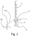
Figure 1 is a perspective view of a part of a machine comprising the first embodiment; -
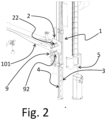
Figure 2 is a close up view of the safety system ofFigure 1 ; -
Figure 3 is a perspective view showing the safety system ofFigure 1 in a first instant during a method of use of the safety system; -
Figure 4 is perspective view showing the safety system ofFigure 1 in a second instant during said method of use; -
Figure 5 is a perspective view showing the safety system ofFigure 1 in a third instant during said method of use; -
Figure 6 is a perspective view showing a second embodiment of the safety system, during a preliminary instant which is to be considered before the first instant; -
Figure 7 shows the second embodiment in the third instant; -
Figure 8 is a perspective view showing a third embodiment of the safety system, during a preliminary instant which is to be considered before the first instant; -
Figure 9 shows the third embodiment in the third instant. - The first embodiment of the safety system is indicated with 1 in
Figures 1-5 . The second embodiment of the safety system is indicated with 1' inFigures 6 and7 . The third embodiment of the safety system is indicated with 1" inFigures 8 and9 . - The
safety system manipulation group 10 for manipulating packaging materials. The machine is configured for the packaging of pourable products and comprises thegroup 10. The machine comprises a vertical upright 5 to which thegroup 10 is mounted. The group is vertically movable with respect to the upright 5, so that thegroup 10 defines the suspended load. The machine comprises thesafety system - The
group 10 comprises anarm 101 and anoperating head 102 supported by thearm 101. The machine can be a palletizing machine, or a depalletizing machine, or a crating machine, or a decrating machine. - The
system stopping device 2 configured for being vertically integral with thegroup 10. - The
system first safety body 3 which is configured for being vertically extended while being fixed to the vertical upright 5. Thefirst safety body 3 is provided with a respective plurality ofholes 31 which are distributed along the extension of saidbody 3. - The
system 1 or 1' comprises asecond safety body second body first body 3 being interposed between saidsecond body second body recesses second body - The second body of the first embodiment is indicated with 4. The second body of the second embodiment is indicated with 4'. The second body of the third embodiment is indicated with 4". The recesses of the first embodiment are indicated with 41. The recesses of the second embodiment are indicated with 41'. The recesses of the third embodiment are indicated with 41".
- The
second body 4 of the first embodiment adopts the operative position inFigures 2 ,3 ,4 ,5 . The second body 4' of the second embodiment adopts the operative position inFigure 7 . Thesecond body 4" of the third embodiment adopts the operative position inFigure 9 . - The
stopping device 2 can adopt a not engaged condition in which thestopping device 2 does not engage any of said holes and recesses. Thestopping device 2 can adopt an engaged condition in which thestopping device 2, with thesecond body hole 31a of thefirst body 3 and one recess 41a or 41a' or 41a" of thesecond body stopping device 2 at least limits a downwards vertical accidental movement of thegroup 10 with respect to the upright 5. Thesecond body first body 3 and the upright 5, in said operative position of thesecond body recess stopping device 2 to prevent a downwards vertical motion of thestopping device 2 with respect to thefirst body 3. - In
Figures 3 ,4 and5 , thesecond body 4 adopts the operative position. InFigure 7 , the second body 4' adopts the operative position. InFigure 9 , thesecond body 4" adopts the operative position. - In
Figure 3 , the stoppingdevice 2 adopts the not engaged condition. InFigures 4 and5 , the stoppingdevice 2 adopts the engaged condition in which it engages said onerecess 41a of thesecond body 4 and onehole 31a of thefirst body 3. InFigure 5 the engagedrecess 41a abuts vertically against the stoppingdevice 2. InFigure 6 , the stoppingdevice 2 adopts the not engaged condition. InFigure 7 , the stoppingdevice 2 adopts the engaged condition in which it engages said onerecess 41a' of the second body 4' and onehole 31a of thefirst body 3. InFigure 7 , the engagedrecess 41a' abuts vertically against the stoppingdevice 2. InFigure 8 , the stoppingdevice 2 adopts the not engaged condition. InFigure 9 , the stoppingdevice 2 adopts an engaged condition in which it engages said onerecess 41a" of thesecond body 4" and onehole 31a of thefirst body 3. InFigure 9 , the engagedrecess 41a" abuts vertically against the stoppingdevice 2. - Between situation of
Figure 4 and situation ofFigure 5 , a vertical movement of thesecond body 4 with respect to thefirst body 3 and theupright 5 occurs. The direction of vertical movement is indicated with arrow V inFigure 4 . - The
first body 3 is fixed to theupright 5. - The stopping
device 2 comprises anactuator 22 and a stoppingpin 21. Theactuator 22 comprises aspring 221 and ajack 222. - In the engaged condition of the stopping
device 2, thepin 21 engages in a vertically slidable manner in said onehole 31a of thefirst body 3. InFigures 4 ,5 ,7 and9 , thepin 21 engages in a vertically slidable manner said onehole 31a of thefirst body 3. InFigure 9 the pin is not visible. - The
jack 222 and thespring 221 are indicated in Figures from 3 to 9. - The
jack 222 prevents thepin 21 from engaging said onehole 31a against the action of thespring 221 so that, by deactivating thejack 222, thespring 221 can push thepin 21 into engagement wit said onehole 31a. - The operative condition of the
safety system jack 222 and to the operative position of thesecond body - In
Figures 3 ,6 and8 , thejack 222 does not adopt a deactivated condition, and therefore thespring 221 is not free to push thepin 21 into engagement with said onehole 31a. InFigures 4 ,5 ,7 and9 , thejack 222 adopts a deactivated condition so that thespring 221 is free to push thepin 21 into engagement with said onehole 31a. - The operative condition of the
safety system 1 or 1' corresponds to the deactivated condition of thejack 222 and to the operative position of thesecond body 4 or 4'. - Each
hole 31 of thefirst body 3 is elongated along the extension of thefirst body 3. - In the deactivated condition of the
jack 222, it can occur that thepin 21 is prevented to engage any hole of thefirst body 3 because it abuts against the material between two consecutive holes, due to the relative vertical position of thepin 21 with respect to thefirst body 3, and therefore due to the specific vertical height of the manipulatinggroup 10. - The elongation of each
hole 31 ensures that, even if in the deactivated condition of the actuator 23 thepin 21 is prevented from engaging with said onehole 31a because of the relative vertical position of thepin 21 with respect to thefirst body 3, and therefore because of the specific vertical height of the manipulatinggroup 10, in case of accidental failure of the brake, thepin 21 will anyway engage with the next hole of thefirst body 3 according to the downwards direction. - This effect is allowed by each
hole 31 being elongated and by thepin 21 being able to be engaged in a vertically slidable manner in each hole of thefirst body 3. - Thanks to the abutment between the stopping
device 2 and said onerecess second body 4, in case of accidental failure of the brake, there will be no vertical motion between the stoppingdevice 2 and thefirst body 3, and therefore no vertical motion between the stoppingdevice 2 and theupright 5, so that also any vertical motion between the manipulatinggroup 10 and theupright 5 will be prevented. - The
first body 3 comprises a respective plate in the form of a strip with the plurality ofrespective holes 31 passing through the whole thickness of the plate. - Each
recess second body 4 or 4' is elongated along the extension of thesecond body 4. - In the first embodiment, each
recess 41a is defined by a respective hole. - In the
first embodiment 1, thesecond body 4 comprises a respective plate in the form of a strip with the plurality ofrespective holes 41 passing through the whole thickness of the plate. - In the second embodiment and third embodiment, the
body 4' or 4" is comb shaped. - In the
first embodiment 1, each hole defining arecess 41a is elongated along the extension of thesecond body 4. - In the
third embodiment 1", in the engaged condition of stoppingdevice 2, thespring 221 engages in a vertically slidable manner said onerecess 41a" and thesecond body 4" is vertically movable with respect to thefirst body 3 and theupright 5, in said operative position of thesecond body 4", so that the engagedrecess 41a" abuts vertically against thespring 221 to prevent a downwards vertical motion of the stoppingdevice 2 with respect to thefirst body 3. In this way thespring 221 can be used both for pushing automatically thepin 21 into engagement with said onehole 31a of thefirst body 3 and for engaging and abutting against said onerecess 41a" of thesecond body 4". - In
Figure 9 , the engagedrecess 41a" vertically abuts against thespring 221. - In the
third embodiment 1", thesecond body 4" is rotatable between said operative position in which thespring 221 is faced towards thesecond body 4", and a not operative position. In the not operative position of thesecond body 4", thespring 221 is not faced towards thesecond body 4" so that thespring 221 cannot engage any of the recesses. - In
Figure 8 , thesecond body 4" adopts the not operative position. InFigure 9 , thesecond body 4" adopts the operative position. - Between situation of
Figure 8 and situation ofFigure 9 , a rotation ofsecond body 4" occurs to switch thesecond body 4" between the not operative position and the operative position. - In the
third embodiment 1", the lateral footprint of the safety system is reduced. - In the
first embodiment 1 and in the second embodiment 1', the stoppingpin 21 can adopt a not engaged position in which thepin 21 does not engage any of said holes and recesses, and an engaged position in which thepin 21, with thesecond body 4 or 4' adopting the operative position, engages in a vertically slidable manner at least said onehole 31a of thefirst body 3 and onerecess second body 4 or 4'. Inn this way, the stoppingdevice 2 can at least limit a downwards vertical accidental movement of thegroup 10 with respect to theupright 5. Thesecond body 4 or 4' is vertically movable with respect to thefirst body 3 and theupright 5, in said operative position of thesecond body 4 or 4', so that the engagedrecess pin 21 to prevent a downwards vertical motion of the stoppingdevice 2 with respect to thefirst body 3. - The engaged condition of the stopping
device 2 corresponds to the engaged position of thepin 21 and the not engaged condition of the stoppingdevice 2 corresponds to the not engaged position of thepin 21. - In
Figure 3 , thepin 21 adopts the not engaged position. InFigures 4 and5 , thepin 21 adopts the engaged condition in which it engages said onerecess 41a of thesecond body 4 and onehole 31a of thefirst body 3. InFigure 5 the engagedrecess 41a abuts vertically against thepin 21. InFigure 6 , thepin 21 adopts the not engaged position. InFigure 7 , thepin 21 adopts the engaged position in which it engages said onerecess 41a' of the second body 4' and onehole 31a of thefirst body 3. InFigure 7 , the engagedrecess 41a' abuts vertically against thepin 21. InFigure 8 , thepin 21 adopts the not engaged position. InFigure 9 , thepin 21 adopts the engaged position in which it engages said onerecess 41a" of the second body 4' and onehole 31a of thefirst body 3. InFigure 9 , the engagedrecess 41a" abuts vertically against thepin 21. InFigure 9 thepin 21 is not visible. - The
jack 222 keeps thepin 21 in the not engaged position against the action of thespring 221 so that, by deactivating thejack 222, thespring 221 can push thepin 21 into said engaged position. - In
Figures 3 ,6 and8 , thejack 222 is not deactivated, and therefore thespring 221 is not free to push thepin 21 into said engaged position. InFigures 4 ,5 ,7 and9 , thejack 222 is deactivated so that thespring 221 is free to push thepin 21 into said engaged position. - In the deactivated condition of the
jack 222, it can occur that thepin 21 is prevented to engage in any recess of thesecond body 4 because it abuts against the material between two consecutive recesses, due to the relative vertical position of thepin 21 with respect to thesecond body 4, and therefore due to the specific vertical height of the manipulatinggroup 10. - The elongation of each
hole 41a orrecess 41a' ensures that, even if in the deactivated condition of thejack 222 thepin 21 is prevented from adopting the engaged position because of the relative vertical position of thepin 21 with respect to thesecond body 4, and therefore because of the specific vertical height of the manipulatinggroup 10, in case of accidental failure of the brake, the pin will anyway engage with the next hole or recess of thesecond body 4 according to the downwards direction. - This is effect is allowed by each
recess 41 being elongated and by thepin 21 being able to be engaged in a vertically slidable manner in anyrecess - Thanks to the abutment between the
pin 21 and said onerecess second body 4 or 4', in case of accidental failure of the brake, there will be no vertical motion between the stoppingdevice 2 and thefirst body 3, and therefore no vertical motion between the stoppingdevice 2 and theupright 5, so that also any vertical motion between the manipulatinggroup 10 and theupright 5 will be prevented. - In the second embodiment, the second body 4' is displaceable between said operative position in which the
first body 3 is interposed between thesecond body 4 and theupright 5, and a not operative position in which thefirst body 3 is not interposed between the second body 4' and theupright 5, so that thepin 21, in the operative position of the second body 4', cannot face and therefore cannot engage any of the recesses. The second body 4' is vertically movable with respect to thefirst body 3 and theupright 5 also in the not operative position. - In
Figure 6 , the second body 4' adopts the not operative position. InFigure 7 , the second body 4' adopts the operative position. - The second embodiment 1' allows the vertical height of the second body 4' to be regulated after the
pin 21 has already engaged thehole 31a of thefirst body 3, to avoid the risk of thepin 21 not being able to engage in any recess because it abuts against material between two consecutive recesses. - In this case, two regulation phases may be performed for regulating the vertical position of the second body 4'. A first one can occur when the second body 4' is adopting the not operative position, and another one when the second body 4' is adopting the operative position. The second phase allows a fine tuning for causing the vertical abutment between the
pin 21 and the engagedrecess 41a' of the second body 4'. - The displacement of the second body 4' is horizontal.
- In all the embodiments, each of the
first body 3 andsecond body - Between situation of
Figure 6 and situation ofFigure 7 , both the displacement of the second body 4' and the vertical movement of the second body 4' occur. - The stopping
device 2 is configured so that, between said not engaged condition and said engaged condition of the stoppingdevice 2, saidpin 21 moves horizontally. - The stopping
device 2 is configured for operating at a first vertical height in said operative condition of thesafety system 1 or 1'. - The
system 1 or 1' comprises a further stoppingdevice 9 which is configured for operating at a second vertical height in the operative condition of thesafety system 1 or 1'. - The further stopping
device 9 comprises at least one further stoppingpin 91 which can adopt a not engaged position in which thefurther pin 91 does not engage any of said holes and recesses, and an engaged position in which thefurther pin 91, with thesecond body 4 or 4' adopting the operative position, engages in a vertically slidable manner at least one further hole of thefirst body 3 and onefurther recess second body 4 or 4'. In this way, also the further stoppingdevice 9 at least limits a downwards vertical accidental movement of thegroup 10 with respect to theupright 5. - The further stopping
device 9 comprises afurther actuator 92. Thefurther actuator 92 comprises afurther spring 921 and afurther jack 922. Thefurther spring 921 and thefurther jack 922 are indicated in Figures from 3 to 9. - The
further jack 922 keeps thefurther pin 91 in the not engaged position against the action of thefurther spring 921 so that, by deactivating thefurther jack 922, thefurther spring 921 can push thefurther pin 91 into said engaged position. The operative condition of thesafety system 1 or 1' corresponds also to the deactivated condition of thefurther jack 922. - The use of the further stopping
device 9 reduces or avoids the risk that in the operative condition of thesystem 1 or 1' there is no engagement between any pin and any hole or recess. - In the situation shown in
Figures 5 and7 , thefurther pin 91 engages thefurther recess second body 4 or 4', but is not engaging any hole of thefirst body 3. - In the situation of
Figure 9 , thefurther spring 921 engages thefurther recess 41b" of thesecond body 4". - The stopping
device 2 is supported by asupport plate 6 which is vertically integral with the manipulatinggroup 10. Also the further stoppingdevice 9 is supported by thesupport plate 6. - The vertical movement of the
second body 4 or 4' is guided by a guiding system comprising a at least one guidingelement 71 or 71'. In the second embodiment, the guiding element 71' is configured for guiding both the movement of the second body 4' between the not operative position and the operative position, and the vertical movement of the second body 4'. To this end, the guiding element 71' presents a C-cross section or a cross section having another shape depending on the type of movement which is needed for switching the second body 4' between the operative position and the not operative position. - The
safety system second body upright 5 and to thefirst body 3. - The
safety system second body upright 5 and to thefirst body 3 is generated automatically, based for example on an input from a user or from a sensor. Thesafety system second body
Claims (18)
- - Safety system (1; 1'; 1") for a vertically movable suspended load corresponding to a manipulation group (10) for manipulating packaging materials, comprising:- a stopping device (2) configured for being vertically integral with the group (10);- a first safety body (3) which is configured for being vertically extended while being fixed to a vertical upright (5), the first safety body (3) being provided with a respective plurality of holes (31) which are distributed along the extension of said body (3);- a second safety body (4; 4'; 4") which is configured for adopting an operative position in which the second body (4; 4'; 4" ) is vertically extended with the first body (3) being interposed between said second body (4; 4'; 4") and said upright (5), the second body (4; 4'; 4") being provided with a respective plurality of recesses (41; 41'; 41") which are distributed along the extension of said second body (4, 4'; 4");wherein the stopping device (2) can adopt a not engaged condition in which the stopping device (2) does not engage any of said holes and recesses, and an engaged condition in which the stopping device (2), with the second body (4; 4'; 4") adopting the operative position, engages in a vertically slidable manner at least one hole (31a) of the first body (3) and one recess (41a; 41a'; 41a'') of the second body (4; 4'; 4"), to at least limit a downwards vertical accidental movement of the group (10) with respect to the upright (5), the second body (4; 4'; 4") being vertically movable with respect to the first body (3) and the upright (5), in said operative position of the second body (4; 4'; 4"), so that the engaged recess (41a; 41a'; 41a") abuts vertically against the stopping device (2) to prevent a downwards vertical motion of the stopping device (2) with respect to the first body (3).
- Safety system (1; 1') according to Claim 1, wherein the stopping device (2) comprises an actuator (22) and a stopping pin (21), the actuator (22) comprising a spring (221) and a jack (222);wherein, in the engaged condition of the stopping device (2), the pin (21) engages in a vertically slidable manner said one hole (31a) of the first body (3);wherein the jack (222) prevents the pin (21) from engaging said one hole (31a) against the action of the spring (221) so that, by deactivating the jack (222), the spring (221) can push the pin (21) in engagement with said one hole (31a), the operative condition of the safety system (1; 1'; 1") corresponding to the deactivated condition of the jack (222) and to the operative position of the second body (4; 4'; 4").
- Safety system (1") according to Claim 2, wherein, in the engaged condition of the stopping device (2), the spring (221) engages in a vertically slidable manner said one recess (41a"), and the second body (4") is vertically movable with respect to the first body (3) and the upright (5), in said operative position of the second body (4"), so that the engaged recess (41a") abuts vertically against the spring (221) to prevent a downwards vertical motion of the stopping device (2) with respect to the first body (3).
- Safety system (1") according to Claim 3, wherein the second body (4") is rotatable between said operative position in which the spring (221) is faced towards the second body (4") and a not operative position in which the spring (221) is not faced towards the second body (4") so that the spring (221) cannot engage any of the recesses.
- Safety system (1; 1') according to Claim 2, wherein:
the stopping device (2) comprises at least one stopping pin (21) which can adopt a not engaged position in which the pin (21) does not engage any of said holes and recesses, and an engaged position in which the pin (21), with the second body (4; 4') adopting the operative position, engages in a vertically slidable manner at least said one hole (31a) of the first body (3) and one recess (41a; 41a') of the second body (4; 4'), to at least limit a downwards vertical accidental movement of the group (10) with respect to the upright (5), the second body (4; 4') being vertically movable with respect to the first body (3) and the upright (5), in said operative position of the second body (4; 4'), so that the engaged recess (41a; 41a') abuts vertically against the pin (21) to prevent a downwards vertical motion of the stopping device (2) with respect to the first body (3), the engaged condition of the stopping device (2) corresponding to the engaged position of the pin (21) and the not engaged condition of the stopping device (2) corresponding to the not engaged position of the pin (21). - Safety system (1; 1') according to Claim 5, wherein the jack (222) keeps the pin (21) in the not engaged position against the action of the spring (221) so that, by deactivating the jack (222), the spring (221) can push the pin (21) into said engaged position.
- Safety system (1, 1') according to Claim 5 or 6, wherein:- the stopping device (2) is configured for operating at a first vertical height in said operative condition of the safety system;- the system (1; 1') comprises a further stopping device (9) which is configured for operating at a second vertical height in the operative condition of the safety system;the further stopping device (9) comprises at least one further stopping pin (91) which can adopt a not engaged position in which the further pin (91) does not engage any of said holes and recesses, and an engaged position in which the further pin (91), with the second body (4; 4') adopting the operative position, engages in a vertically slidable manner at least one further hole of the first body (3) and one further recess (41b; 41b') of the second body (4; 4'), to at least limit a downwards vertical accidental movement of the group (10) with respect to the upright (5).
- Safety system (1; 1') according to Claims 6 and 7, wherein the further stopping device (9) comprises a further actuator (92), the further actuator (92) comprising a further spring (921) and a further jack (922);
wherein the further jack (922) keeps the further pin (91) in the not engaged position against the action of the further spring (921) so that, by deactivating the further jack (922), the further spring (921) can push the further pin (91) into said engaged position, the operative condition of the safety system (1; 1') corresponding also to the deactivated condition of the further jack (922). - Safety system (1) according to Claim any of Claims from 5 to 8, wherein each recess (41) is defined by a respective hole.
- Safety system (1) according to Claim 9, wherein each hole defining a recess is elongated along said extension of the second body (4), the second body (4) comprising preferably a respective plate in the form of a strip with the plurality of respective holes (41) passing through the whole thickness of the plate.
- Safety system (1') according to any of Claims from 5 to 8, wherein the second body (4') is displaceable between said operative position in which the first body (3) is interposed between the second body (4') and the upright (5) and a not operative position in which the first body (3) is not interposed between the second body (4) and the upright (5) so that, in said not operative position of the second body (4'), the pin (21) cannot engage any of the recesses, the second body (4') being vertically movable with respect to the first body (3) and to the upright (5) both in the not operative position and in the operative position.
- Safety system (1'; 1") according to Claim 4 or 11, wherein the second body (4'; 4") is comb shaped.
- Safety system (1'; 1") according to Claim 4 or 11 or 12, comprising a guiding element (71') which is configured for guiding both the vertical movement of the second body (4'; 4") with respect to the first body (3) and the upright (5), and the movement of the second body (4'; 4") between the not operative position and the operative position, the guiding element (71') having preferably a C-cross section.
- Safety system (1; 1'; 1") according to any of the claims from 2 to 12, wherein the stopping device (2) is configured so that, between said not engaged condition and said engaged condition, said pin (21) moves horizontally.
- Safety system (1; 1'; 1") according to any of the previous Claims, wherein:each hole of the first body (3) is elongated along said extension of the first body (3), the first body (3) comprising preferably a respective plate in the form of a strip with the plurality of respective holes (31) passing through the whole thickness of the plate;each recess (41; 41'; 41") of the second body (4; 4'; 4") is elongated along said extension of the second body (4; 4'; 4");each of said first body (3) and second body (4, 4'; 4") is elongated along the respective extension.
- Safety system (1; 1'; 1") according to any of the previous Claims, wherein the second body (3) is fixed to the upright (5).
- Machine for the packaging of pourable products, comprising:- a manipulating group (10) for manipulating packaging materials;- an upright (5) to which the group (10) is mounted to be vertically movable with respect to the upright (5), so that the group (10) defines a suspended load;- a safety system (1; 1'; 1") according to any of the previous Claims.
- Machine according to Claim 17, wherein:- the group (10) comprises an operating head (102) and an arm (101) supporting the operating head (102);- the machine is a palletizing machine, or- the machine is a depalletizing machine, or- the machine is a crating machine, or- the machine is a decrating machine.
Priority Applications (2)
| Application Number | Priority Date | Filing Date | Title |
|---|---|---|---|
| EP23193325.0A EP4512582B1 (en) | 2023-08-24 | 2023-08-24 | Safety system for a manipulating group for manipulating packaging materials |
| PCT/EP2024/072388 WO2025040450A1 (en) | 2023-08-24 | 2024-08-07 | Safety system for a manipulating group for manipulating packaging materials |
Applications Claiming Priority (1)
| Application Number | Priority Date | Filing Date | Title |
|---|---|---|---|
| EP23193325.0A EP4512582B1 (en) | 2023-08-24 | 2023-08-24 | Safety system for a manipulating group for manipulating packaging materials |
Publications (2)
| Publication Number | Publication Date |
|---|---|
| EP4512582A1 true EP4512582A1 (en) | 2025-02-26 |
| EP4512582B1 EP4512582B1 (en) | 2026-04-15 |
Family
ID=87801173
Family Applications (1)
| Application Number | Title | Priority Date | Filing Date |
|---|---|---|---|
| EP23193325.0A Active EP4512582B1 (en) | 2023-08-24 | 2023-08-24 | Safety system for a manipulating group for manipulating packaging materials |
Country Status (2)
| Country | Link |
|---|---|
| EP (1) | EP4512582B1 (en) |
| WO (1) | WO2025040450A1 (en) |
Citations (4)
| Publication number | Priority date | Publication date | Assignee | Title |
|---|---|---|---|---|
| US20080014071A1 (en) * | 2006-07-11 | 2008-01-17 | United Technologies Corporation | Safety interlock system for mechanical manipulators |
| CN111136418A (en) * | 2020-02-25 | 2020-05-12 | 株洲中车特种装备科技有限公司 | High-precision welding positioner |
| CN114683250A (en) * | 2022-03-25 | 2022-07-01 | 中铁科工集团有限公司 | Lifting anti-falling assembly and welding robot |
| CN219341631U (en) * | 2023-02-27 | 2023-07-14 | 青岛瑞鑫源物流设备有限公司 | Anti-falling mechanism of vertical elevator |
-
2023
- 2023-08-24 EP EP23193325.0A patent/EP4512582B1/en active Active
-
2024
- 2024-08-07 WO PCT/EP2024/072388 patent/WO2025040450A1/en not_active Ceased
Patent Citations (4)
| Publication number | Priority date | Publication date | Assignee | Title |
|---|---|---|---|---|
| US20080014071A1 (en) * | 2006-07-11 | 2008-01-17 | United Technologies Corporation | Safety interlock system for mechanical manipulators |
| CN111136418A (en) * | 2020-02-25 | 2020-05-12 | 株洲中车特种装备科技有限公司 | High-precision welding positioner |
| CN114683250A (en) * | 2022-03-25 | 2022-07-01 | 中铁科工集团有限公司 | Lifting anti-falling assembly and welding robot |
| CN219341631U (en) * | 2023-02-27 | 2023-07-14 | 青岛瑞鑫源物流设备有限公司 | Anti-falling mechanism of vertical elevator |
Also Published As
| Publication number | Publication date |
|---|---|
| WO2025040450A1 (en) | 2025-02-27 |
| EP4512582B1 (en) | 2026-04-15 |
Similar Documents
| Publication | Publication Date | Title |
|---|---|---|
| US9145283B2 (en) | Lifting apparatus with safety device | |
| US5516255A (en) | Clamping apparatus | |
| JP3012184U (en) | Folding press machine | |
| EP2258650B1 (en) | Emergency braking system for an elevator | |
| KR102624949B1 (en) | forming tool | |
| EP2354054B1 (en) | Loading and unloading station | |
| EP4512582B1 (en) | Safety system for a manipulating group for manipulating packaging materials | |
| CN101177207B (en) | Stacker with mechanical hand protecting means | |
| US3973416A (en) | Knitting machine | |
| CN201010369Y (en) | Palletizer with mechanical arm protecting equipment | |
| KR920003669B1 (en) | Pedal mechanism of the sewing machine | |
| WO2019073498A1 (en) | Grip and block system for a forklift truck and related forklift truck | |
| US6789659B2 (en) | Stator winding system and method with pallet on pallet arrangement | |
| EP0566195A1 (en) | Safety ratchet device | |
| US4827758A (en) | Upper tool support for a stamping machine or the like | |
| US3250402A (en) | Safety brake | |
| AU2019268186B2 (en) | Assembly for a dosing system of a spreader machine for distributing a granular material or the like, dosing system and spreader machine | |
| US4033571A (en) | Positioning arrangement | |
| JPS6348648B2 (en) | ||
| GB2395695A (en) | Trailer/container with variable height loading deck | |
| KR100328165B1 (en) | Guiding apparatus of a container for automatic packing | |
| US4219295A (en) | Apparatus for parking motor vehicles | |
| EP0571339A2 (en) | Gripping device particularly suited for gripping and handling stacks of panels in panel sectioning machines | |
| JP7094977B2 (en) | Manufacturing equipment with protection unit | |
| KR100227069B1 (en) | Box pallet |
Legal Events
| Date | Code | Title | Description |
|---|---|---|---|
| PUAI | Public reference made under article 153(3) epc to a published international application that has entered the european phase |
Free format text: ORIGINAL CODE: 0009012 |
|
| STAA | Information on the status of an ep patent application or granted ep patent |
Free format text: STATUS: THE APPLICATION HAS BEEN PUBLISHED |
|
| AK | Designated contracting states |
Kind code of ref document: A1 Designated state(s): AL AT BE BG CH CY CZ DE DK EE ES FI FR GB GR HR HU IE IS IT LI LT LU LV MC ME MK MT NL NO PL PT RO RS SE SI SK SM TR |
|
| STAA | Information on the status of an ep patent application or granted ep patent |
Free format text: STATUS: REQUEST FOR EXAMINATION WAS MADE |
|
| 17P | Request for examination filed |
Effective date: 20250813 |
|
| GRAP | Despatch of communication of intention to grant a patent |
Free format text: ORIGINAL CODE: EPIDOSNIGR1 |
|
| STAA | Information on the status of an ep patent application or granted ep patent |
Free format text: STATUS: GRANT OF PATENT IS INTENDED |
|
| INTG | Intention to grant announced |
Effective date: 20251209 |
|
| GRAS | Grant fee paid |
Free format text: ORIGINAL CODE: EPIDOSNIGR3 |
|
| GRAA | (expected) grant |
Free format text: ORIGINAL CODE: 0009210 |
|
| STAA | Information on the status of an ep patent application or granted ep patent |
Free format text: STATUS: THE PATENT HAS BEEN GRANTED |
|
| AK | Designated contracting states |
Kind code of ref document: B1 Designated state(s): AL AT BE BG CH CY CZ DE DK EE ES FI FR GB GR HR HU IE IS IT LI LT LU LV MC ME MK MT NL NO PL PT RO RS SE SI SK SM TR |
|
| REG | Reference to a national code |
Ref country code: CH Ref legal event code: F10 Free format text: ST27 STATUS EVENT CODE: U-0-0-F10-F00 (AS PROVIDED BY THE NATIONAL OFFICE) Effective date: 20260415 |
|
| P01 | Opt-out of the competence of the unified patent court (upc) registered |
Free format text: CASE NUMBER: UPC_APP_0010732_4512582/2026 Effective date: 20260324 |
|
| REG | Reference to a national code |
Ref country code: DE Ref legal event code: R096 Ref document number: 602023015200 Country of ref document: DE |
|
| REG | Reference to a national code |
Ref country code: IE Ref legal event code: FG4D |