EP4512529A1 - A method of separating a liquid mixture in a centrifugal separator - Google Patents
A method of separating a liquid mixture in a centrifugal separator Download PDFInfo
- Publication number
- EP4512529A1 EP4512529A1 EP23192557.9A EP23192557A EP4512529A1 EP 4512529 A1 EP4512529 A1 EP 4512529A1 EP 23192557 A EP23192557 A EP 23192557A EP 4512529 A1 EP4512529 A1 EP 4512529A1
- Authority
- EP
- European Patent Office
- Prior art keywords
- centrifuge bowl
- speed
- sludge space
- outlet
- space
- Prior art date
- Legal status (The legal status is an assumption and is not a legal conclusion. Google has not performed a legal analysis and makes no representation as to the accuracy of the status listed.)
- Pending
Links
Images

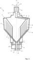


Classifications
-
- B—PERFORMING OPERATIONS; TRANSPORTING
- B04—CENTRIFUGAL APPARATUS OR MACHINES FOR CARRYING-OUT PHYSICAL OR CHEMICAL PROCESSES
- B04B—CENTRIFUGES
- B04B1/00—Centrifuges with rotary bowls provided with solid jackets for separating predominantly liquid mixtures with or without solid particles
- B04B1/04—Centrifuges with rotary bowls provided with solid jackets for separating predominantly liquid mixtures with or without solid particles with inserted separating walls
- B04B1/08—Centrifuges with rotary bowls provided with solid jackets for separating predominantly liquid mixtures with or without solid particles with inserted separating walls of conical shape
-
- B—PERFORMING OPERATIONS; TRANSPORTING
- B04—CENTRIFUGAL APPARATUS OR MACHINES FOR CARRYING-OUT PHYSICAL OR CHEMICAL PROCESSES
- B04B—CENTRIFUGES
- B04B11/00—Feeding, charging, or discharging bowls
- B04B11/02—Continuous feeding or discharging; Control arrangements therefor
-
- B—PERFORMING OPERATIONS; TRANSPORTING
- B04—CENTRIFUGAL APPARATUS OR MACHINES FOR CARRYING-OUT PHYSICAL OR CHEMICAL PROCESSES
- B04B—CENTRIFUGES
- B04B11/00—Feeding, charging, or discharging bowls
- B04B11/08—Skimmers or scrapers for discharging ; Regulating thereof
- B04B2011/086—Skimmers or scrapers for discharging ; Regulating thereof with a plurality of scraper blades
Definitions
- the present invention relates to the field of centrifugal separators, and more specifically to a method of separating a liquid mixture into a light phase and a heavy phase with a centrifugal separator.
- Centrifugal separators are generally used for separation of liquids and/or for separation of solids from a liquid.
- liquid mixture to be separated is introduced into a rotating bowl and heavy particles or denser liquid, usually water, accumulates at the periphery of the rotating bowl whereas less dense liquid accumulates closer to the central axis of rotation. This allows for collection of the separated fractions, e.g. by means of different outlets arranged at different radii from the rotational axis.
- a centrifugal separator for clarification of beer is disclosed in WO2021058287 .
- This document describes a centrifugal separator with a first outlet for the clarified liquid, a second outlet for yeast concentrate and a third outlet for intermittent discharge at the periphery of the centrifuge bowl.
- the yeast concentrate is flowing into a set of pipes from a position close to the periphery in the sludge space to the second outlet.
- the discharge frequency can be lowered and yeast cells leaving the centrifugal separator by the second outlet, have a high probability to survive the centrifugation and may be used for the next brewing batch, while much of the yeast cells that are ejected at the intermittent discharges in the third outlet are dead and are not usable in further fermentation.
- the centrifugal separator comprises
- the method comprises the steps of
- the centrifugal separator may be a disc stack centrifugal separator, i.e. the centrifuge bowl may comprise a stack of separation discs in the separation space.
- the centrifuge bowl may be part of a replaceable single use insert or a complete replaceable single use insert, as described in e.g. WO2020120357A1 , or it may be a traditional centrifuge bowl for multiple use. Further, the centrifugal separator may be as discussed in relation to the second aspect below.
- the method is for separating a liquid mixture into at least a light phase and a heavy phase in a centrifugal separator.
- the light phase may be a liquid light phase and the heavy phase may be a liquid heavy phase.
- the heavy phase has a density that is higher than the density of the light phase.
- the method may comprise separating the liquid mixture into a light phase, a heavy phase and a sludge phase in a centrifugal separator.
- Step a) of rotating the bowl at a first speed comprises using the drive member for rotating the centrifuge bowl.
- the first speed is the operational speed of the centrifugal separator, i.e. the speed during which separation occurs in the separation space. This speed may be around 5000 - 10 000 rpm.
- Step b) of supplying the liquid mixture may comprise pumping liquid mixture to the inlet of the centrifuge bowl. Step a) and b) thus also involves separating the liquid mixture into the light phase and the heavy phase.
- the member in the sludge space thus rotates at a differential speed, higher or lower, compared to the bowl.
- Step d) involves discharging the light phase and the heavy phase form its outlets, respectively.
- the first aspect of the invention is based on the insight that rotating the member in the sludge space at a differential speed, the member may sweep the circumference of the sludge space and therefore allow for efficient pick up of the heavy phase.
- the member in the sludge space may be the at least one outlet conduit itself so that the actual conduit or conduits sweeps the circumference of the sludge space, or the member may be a scraper that sweeps the sludge space in order to push and transport the heavy phase to the outlet conduit or conduits, which then may be stationary relative the centrifuge bowl.
- steps c) and a) are performed simultaneously so that the member in the sludge space rotates at a differential speed as compared to the centrifuge bowl to sweep the full inner circumference of the sludge space.
- the differential speed between the member and bowl may be less than 100 rpm, such than less than 75 rpm, such as less than 50 rpm.
- the at least one conduit may be arranged for continuous removal of a liquid heavy phase from the sludge space. Further, the at least one conduit may be a plurality of conduits or a single conduit. The plurality of outlet conduits may be equidistantly arranged around the axis of rotation (X). The at least one conduit may be arranged along the upper inner wall of the centrifuge bowl.
- the at least one conduit may also be arranged within the wall of the centrifuge bowl but have an inlet opening arranged so that heavy phase in the sludge space may enter the at least one outlet conduit.
- the member in the sludge space is the at least one outlet conduit.
- the at least on conduit takes the form as a single pipe or a plurality of pipes extending into the sludge space.
- the member in the sludge space is at least one scraper for scraping heavy phase in the sludge space.
- the at least one scraper may thus be arranged for sweeping the heavy phase in the sludge space in a different speed than the rotation of the centrifuge bowl. Scraping heavy phase in the sludge space may thus involve pushing heavy phase in the circumferential direction so that it more easily may enter the at least one outlet conduit.
- the at least one scraper may be arranged for scraping heavy phase along the inner peripheral wall of the centrifuge bowl.
- the at least one outlet conduit is preferably arranged for rotating with the bowl, i.e. at the first speed.
- the at least one outlet conduit is then preferably stationary relative the bowl.
- the member in the sludge space is the at least one outlet conduit onto which at least one scraper is attached.
- both the at least one outlet conduit and the at least one scraper may rotate at the second speed, and a scraper may then be arranged or angled for guiding the heavy phase into an outlet conduit.
- the second speed of the member in the sludge space is lower than the first speed of the centrifuge bowl.
- step c) may comprise decreasing the rotational speed of the member in the sludge space with a braking unit so that the second speed of the member in the sludge space is lower than the first speed of the centrifuge bowl.
- the member in the sludge space may be arranged within the centrifuge bowl such that without the braking unit, or with the braking unit turned off, the member in the sludge space would rotate at the first speed of the centrifuge bowl.
- the second speed of the member in the sludge space is higher than the first speed of the centrifuge bowl.
- the member in the sludge space is arranged for freely rotating in the sludge space relative the centrifuge bowl.
- the member in the sludge space may be further arranged such that the flow of the liquid mixture, the light phase or the heavy phase within the bowl rotates said member in the sludge space at said second speed in step c).
- the member in the sludge space may be connected to or comprise a parts that has wings that extend in the axial direction so that the impact of the liquid mixture to be separated or any of the separated phases drives the member in the sludge space to rotation at the second speed, which may then be lower than the first speed of the centrifuge bowl.
- the member in the sludge space may be the at least one outlet conduit, which thus may be arranged for freely rotating in the sludge space relative the centrifuge bowl. Then transport of the heavy phase through the conduits may rotate the at least one outlet conduit at a second speed, which may then be higher than the first speed.
- centrifugal separator for separating a liquid mixture into at least a light phase and a heavy phase.
- the centrifugal separator is comprising
- This aspect may generally present the same or corresponding advantages as the former aspect. Effects and features of this second aspect are largely analogous to those described above in connection with the first aspect. Embodiments mentioned in relation to the first aspect are largely compatible with the second aspect of the invention.
- the centrifugal separator of the second aspect may thus be used to perform the method of the first aspect discussed above.
- the term “axially” denotes a direction which is parallel to the rotational axis (X). Accordingly, relative terms such as “above”, “upper”, “top”, “below”, “lower”, and “bottom” refer to relative positions along the rotational axis (X).
- the term “radially” denotes a direction extending radially from the rotational axis (X). A “radially inner position” thus refers to a position closer to the rotational axis (X) compared to "a radially outer position”.
- the centrifugal separator may be a single use centrifugal separator.
- the centrifuge bowl may form at least a part of an exchangeable unit made for single use, whereas the drive unit is for multiple use. A new centrifuge bowl may then be used before each separation process.
- the single use bowl may be as described in WO2020120357A1 .
- the single use centrifuge bowl may be of a polymeric material or at least comprise to a larger extent a polymeric material, such as plastic.
- the centrifuge bowl the centrifuge bowl is part of an exchangeable single use insert or a complete exchangeable single use insert .
- the centrifuge bowl may be for multiple use and may comprise or consist of stainless steel.
- Such a centrifuge bowl is described in e.g. WO2021058287 A1 .
- the centrifuge bowl is for multiple use.
- the centrifugal separator is for separation of a liquid mixture.
- the liquid mixture may be an aqueous liquid or an organic liquid.
- the centrifugal separator may be for separating a liquid mixture into at least a liquid light phase and a liquid heavy phase and potentially also a sludge from the liquid mixture.
- the liquid heavy phase has a density that is higher than the density of the light phase.
- the centrifuge bowl may be enclosed in a hood, which forms part of a stationary frame.
- the centrifuge bowl may be supported by the frame by at least one bearing device and be arranged to be rotated around vertical axis of rotation, i.e. the axis of rotation (X) may extend vertically.
- the centrifuge bowl is usually supported by a spindle, i.e. a rotatable shaft, and may thus be mounted to rotate with the spindle. Consequently, the centrifugal separator may comprise a spindle that is rotatable around the axis of rotation (X).
- the centrifugal separator may be arranged such that the centrifuge bowl is supported by the spindle at one of its ends, such at the bottom end or the top end of the spindle.
- the drive member for rotating the centrifuge bowl may comprise an electrical motor having a rotor and a stator.
- the rotor may be fixedly connected to the rotatable part, such as to a spindle.
- the drive member may be provided beside the spindle and rotate the rotatable part by a suitable transmission, such as a belt or a gear transmission.
- the centrifuge bowl encloses by its walls a separation space and a sludge space.
- the centrifugal separator may be a disc stack centrifugal separator. Therefore, the separation space may comprise a stack of separation discs arranged coaxially around the axis of rotation (X) and the sludge space may then be arranged radially outside the stack of separation discs.
- the separation discs may e.g. be of metal or a polymer. Further, the separation discs may be frustoconical separation discs, i.e. having separation surfaces forming frustoconical portions of the separation discs. Radially outside of the stack of separation discs is the sludge space, in which separated sludge and liquid heavy phase is collected during operation.
- the sludge space thus extends radially from the outer portion of the stack of separation discs to the inner wall of the centrifuge bowl.
- the separation discs are arranged coaxially around the axis of rotation (X) at a distance from each other to form passages between each two adjacent separation discs.
- the stack of separation discs thus forms a surface enlarging insert that increases the separation efficiency as liquid mixture flows in the passages of the stack.
- the stack of separation discs comprises more than 100 separation discs.
- the centrifugal separator also comprises an inlet for receiving the liquid mixture to be separated (the liquid mixture).
- This inlet may be arranged centrally in the centrifuge bowl, thus at rotational axis (X).
- the centrifugal separator may be arranged to be fed from the bottom, such as through a spindle, so that the liquid mixture is delivered to the inlet from the bottom of the separator.
- the centrifugal separator may be arranged to be fed from the top, through a stationary inlet pipe extending into the centrifuge bowl to the inlet.
- the centrifuge bowl comprises outlets for the separated phases.
- the first outlet for the light phase may be in fluid connection with a stationary light phase outlet pipe
- the second outlet for the heavy phase may be in fluid connection with a stationary heavy phase outlet pipe.
- the first and second outlets may be arranged on the upper portion of the centrifuge bowl.
- the centrifuge bowl may comprise sludge outlets.
- the sludge outlet is in the form of a set of intermittently openable outlets arranged at the periphery of the centrifuge bowl.
- the intermittently openable outlets may be equidistantly spaced around the axis of rotation (X). Consequently, in embodiments of the first aspect, the centrifugal separator is comprising sludge outlets at the periphery of the centrifuge bowl.
- the sludge outlets may be in the form of a set of intermittently openable outlets.
- the sludge outlets may be nozzles arranged for continuous discharge of a separated sludge phase.
- the inlet may be sealed by a hermetically sealed, such as with a mechanical hermetic seal.
- the at least one outlet conduit may be a single conduit or a plurality of conduits.
- the at least one conduit may be arranged for continuous removal of heavy phase from the sludge space. Further, the at least one conduit may be arranged along the upper inner wall of the centrifuge bowl.
- a plurality of outlet conduits may be equidistantly arranged around the axis of rotation (X).
- the plurality of outlet conduits are formed as pipes at their inlet end portions. Further, the plurality of outlet conduits may be formed as a plurality of pipes extending all the way to the second outlet.
- the at least one outlet conduit may be arranged above a disc stack, such as above a top disc arranged over the disc stack.
- a top disc may be thicker than the separation discs of the disc stack.
- the top disc may also be used in the axial compression of the disc stack within the centrifuge bowl.
- the member in the sludge space is arranged to be rotated at the second speed simultaneously as the centrifuge bowl is rotated at its first speed. During operation, there is thus a differential speed between the member in the sludge space and the centrifuge bowl. As discussed in relation to the first aspect above, the second speed may be lower or higher than the first speed.
- the member in the sludge space is the at least one outlet conduit.
- the outlet conduit or conduits may be arranged to be rotated at the second speed.
- the member in the sludge space is at least one scraper for scraping heavy phase in the sludge space.
- the at least one scraper may have a scraper surface having a normal extending in an angle relative the rotational axis.
- the scraper surface may be arranged in an axial plane, i.e. a plane having a normal extending in a plane that is perpendicular to the rotational axis (X).
- the at least one scraper may be arranged for scraping heavy phase along the inner peripheral wall of the centrifuge bowl.
- the centrifugal separator further comprises a differential speed unit arranged for rotating the member in the sludge space at the second speed.
- the differential speed unit may at least comprise a portion that is arranged in the stationary part of the centrifugal separator.
- the differential speed unit may for example be a drive unit other than the drive unit used for driving the centrifuge bowl.
- the differential speed unit may be a motor, such as an electrical motor, for driving the member in the sludge space at the second speed.
- the differential speed unit is a braking unit for decreasing the speed of the member in the sludge space in order to rotate the member in the sludge space at a second speed that is lower than the first speed.
- the braking unit may be an electromagnetic brake.
- Such electromagnetic brake may comprise a first portion in the centrifuge bowl and a second portion in a stationary part of the centrifugal separator. The first part is connected to the member in the sludge space that is to be rotated at the second speed.
- the electromagnetic brake may be an Eddy current brake, in which the first portion in the centrifuge bowl comprises a conductive surface of e.g. cupper or aluminium that is arranged in close proximity to the second portion, which is in the form of an electromagnet arranged in the stationary part of the centrifugal separator.
- the conductive surface is arranged at a distance from the electromagnet such that circular electric currents may be induced in the conductive surface during rotation.
- Such circulating currents may create magnetic fields that opposes the magnetic field of the electromagnet, thereby leading to a decrease of the speed of the first portion of the electromagnetic brake and thus a decreased speed of the member in the sludge space.
- the electromagnetic brake may comprise a first portion in the centrifuge bowl in the form of at least one permanent magnet, and the second portion in the stationary part of the centrifugal separator may comprise at least one electric coil.
- the member in the sludge space is connected to the first portion, and when this rotates, the at least one permanent magnet induces an electromotive force in the windings of the at least one electric coil. Therefore a braking force for the member in the sludge space may occur if a load is applied to the at least one coil of the second portion.
- the braking unit may be a friction brake.
- Such friction brake may comprise a rotatable part that is connected to the member in the sludge space.
- This rotatable part may in turn comprise a plurality of wings or toroidal pockets arranged as a liquid brake, i.e. arranged for stealing energy from the rotating member in the sludge space and by that decrease the member in the sludge space to its second speed.
- the friction brake e.g. in the form of a liquid brake, may be arranged as a seal, e.g. for sealing the second outlet of the centrifugal separator.
- the member in the sludge space is arranged to rotate freely from the centrifuge bowl. This may be achieved in several ways. As an example, the member in the sludge space may be arranged with a sliding surface against a portion of the centrifuge bowl or it may be arranged with a separate bearing.
- the centrifugal separator is further comprising at least one bearing for journalling said member in the sludge space, and wherein the at least one bearing does not support said centrifuge bowl and is arranged to allow the member in the sludge space to rotate freely in the sludge space in relation to the centrifuge bowl at said second speed.
- the at least one bearing does not support said centrifuge bowl and is arranged to allow the member in the sludge space to rotate freely in the sludge space in relation to the centrifuge bowl at said second speed.
- the member in the sludge space may be connected to or comprise a parts that has wings that extend in the axial direction so that the impact of the liquid mixture to be separated or any of the separated phases drives the member in the sludge space to rotation at the second speed, which may then be lower than the first speed of the centrifuge bowl.
- the member in the sludge space may be the at least one outlet conduit, which thus may be arranged for freely rotating in the sludge space relative the centrifuge bowl. Then transport of the heavy phase through the conduits may rotate the at least one outlet conduit at a second speed, which may then be higher than the first speed.
- Figs. 1 and 2 schematically show an example of centrifugal separator and a centrifuge bowl according to the present disclosure. The method of the present invention may thus be performed in the centrifugal separator discussed in relation to Figs. 1 and 2 .
- Fig. 1 show a cross-section of an embodiment of a centrifugal separator 1 configured to separate a heavy phase and a light phase from a liquid mixture.
- the centrifugal separator 1 has a rotatable part 4, comprising the centrifuge bowl 5 and drive spindle 4a.
- the centrifugal separator 1 is further provided with a drive motor 3.
- This motor 3 may for example comprise a stationary element and a rotatable element, which rotatable element surrounds and is connected to the spindle 4a such that it transmits driving torque to the spindle 4a and hence to the centrifuge bowl 5 during operation.
- the drive motor 3 may be an electric motor.
- the drive motor 3 may be connected to the spindle 4a by transmission means such as a drive belt or the like, and the drive motor may alternatively be connected directly to the spindle 4a.
- the centrifuge bowl 5, shown in more detail in Fig. 2 is supported by the spindle 4a, which is rotatably arranged in stationary frame 2 around the vertical axis of rotation (X) in a bottom bearing 22 and a top bearing 21.
- the stationary frame 2 has an upper hood that surrounds centrifuge bowl 5.
- liquid mixture to be separated is fed to the bottom to the centrifuge bowl 5 via the drive spindle 4a.
- the drive spindle 4a is thus in this embodiment a hollow spindle, through which the feed is supplied to the centrifuge bowl 5.
- the liquid mixture to be separated is supplied from the top, such as through a stationary inlet pipe extending into the centrifuge bowl 5.
- Fig. 2 shows a more detailed view of the centrifuge bowl 5 of the centrifugal separator 1.
- the centrifuge bowl 5 forms within itself a separation space 9a and a sludge space 9b, located radially outside the separation space 9a.
- a stack 10 of separation discs is arranged coaxially around the axis of rotation (X) and axially below a top disc 50.
- the stack 10 is arranged to rotate together with the centrifuge bowl 5 and provides for an efficient separation of the liquid mixture into at least a liquid light phase and a liquid heavy phase.
- the sludge space 9b is in this embodiment confined between an inner surface of the centrifuge bowl wall 13 and an axially movable operating slide 16.
- the disc stack 10 is supported at its axially lowermost portion by distributor 11.
- the distributor is arranged to conduct liquid mixture from the center inlet 14 of the centrifuge bowl 5 to a predetermined radial level in the separation space 9a.
- the inlet 14 is arranged for receiving the liquid mixture and is in the form of a central inlet chamber formed within or under the distributor 11.
- the inlet 14 communicates with the separation space 9a via passages 17 formed in the distributor 11.
- the outlet conduit are arranged axially above the top disc 50 and in close proximity of the surrounding upper inner wall of the centrifuge bowl 5. Further, the outlet conduits 30 are arranged with an upward tilt relative the radial plane from the inlet end portions 31 to the conduit outlet 32.
- the centrifuge bowl 5 comprises at least four outlet conduits 30, such as at least 8 outlet conduits 30, such as at least twelve outlet conduits 30.
- the centrifuge bowl 5 may comprises a single outlet conduit.
- the outlet conduits are arranged for being rotated at a speed (second speed) other than the speed of the centrifuge bowl 5 (first speed) during operation of the centrifugal separator. This is to facilitate transport of heavy phase from the sludge space 9b into the outlet conduits 30. This will further be discussed below, especially in relation to Figs. 4-8 .
- the radially inner portion of the disc stack 10 communicates with a first outlet 7 for a separated light phase of the liquid mixture.
- This first outlet 7 of the centrifuge bowl 5 communicates with a stationary outlet pipe 7a for discharging the separated liquid light phase from the centrifuge bowl 5.
- the first and second outlet chambers 6, 7 are mechanically sealed with seals 12a, 12b. As this is an airtight design, they are also often called hermetic seals.
- the inlet channel 4b is also sealed at lower end of the hollow spindle 4a, thus preventing communication between the inlet channel 4b and the surroundings. This mechanical seal is not shown in the Figures.
- the centrifuge bowl 5 is further provided with outlets 15 at the radially outer periphery of the sludge space 9b. These outlets 15 are evenly distributed around the rotor axis (X) and are arranged for intermittent discharge of a sludge component of the liquid mixture.
- the opening of the outlets 15 is controlled by means of an operating slide 16 actuated by operating water channels below the operating slide 16, as known in the art. In its position shown in the drawing, the operating slide 16 abuts sealingly at its periphery against the upper part of the centrifuge bowl 5, thereby closing the sludge space 9b from connection with outlets 15, which are extending through the centrifuge bowl 5.
- the centrifuge bowl 5 is brought into rotation by the drive motor 3. Via the spindle 4a, liquid mixture to be separated is brought into the separation space 9a, as indicated by arrow "A".
- different phases in the liquid mixture is separated between the separation discs of the stack 10. Heavier component, such as a liquid heavy phase and a sludge phase, move radially outwards between the separation discs of the stack 10 to the sludge space 9b, whereas the phase of lowest density, such as a liquid light phase, moves radially inwards between the separation discs of the stack 10 and is forced through the outlet pipe 7a via the first outlet 7, as indicated by arrow "C".
- the liquid of higher density is instead discharged via the outlet conduits 30 to the second outlet 6 and further out via stationary outlet pipe 6a, as indicated by arrow "B".
- the plurality of outlet conduits or pipes 30 are rotated at a second speed that is other than the first speed of the centrifuge bowl 5.
- the plurality of outlet conduits or pipes 30 are rotated at a differential speed as compared to the bowl 5. This speed may be higher or lower than the speed of the bowl, but has the effect that the outlet conduits 30 sweeps the full turn of the sludge space 9b during operation, thereby enhancing pick-up of separated heavy phase from the sludge space 9b. How this may be achieved is further discussed in relation to Figs. 4-7 below.
- Solids, or sludge which accumulate at the periphery of the sludge space 9b and is emptied intermittently from within the centrifuge bowl by the sludge outlets 15 being opened, whereupon sludge is discharged from the separation chamber 15 by means of centrifugal force, as indicated by arrow "D".
- the discharge of sludge may also take place continuously, in which case the sludge outlets 15 take the form of open nozzles and a certain flow of sludge and/or heavy phase is discharged continuously by means of centrifugal force.
- the centrifugal separator may also be in the form of a single-use centrifugal separator, such as a separator shown in WO2020120357A1 .
- the separator may thus comprise a drive unit in which an exchangeable single use centrifuge bowl 5 is inserted.
- An example of such an exchangeable single use centrifuge bowl 5 is shown in Fig. 3 .
- Fig. 3 shows a schematic illustration of cross-section of an embodiment of exchangeable separation insert 5a of the present disclosure.
- the insert 5a comprises a centrifuge bowl 5 arranged to rotate around rotational axis (X) and arranged between a first, lower stationary portion 27 and a second, upper stationary portion 28.
- the whole insert 5a or at least the bowl 5 may comprise or consist of a polymeric material.
- the inlet 14 in the bowl 5 is in this example arranged at a lower axial portion of the bowl 5, and the liquid mixture is supplied via a stationary inlet conduit 4b arranged in the first stationary portion 27.
- the stationary inlet conduit 4b is arranged at the rotational axis (X) so that the material to be separated is supplied at the rotational centre.
- the centrifuge bowl 5 encloses separation space 9a and radially sludge space 9b. There is further a stack 10 of frustoconical separation discs arranged coaxially in the separation space 9a. The separation discs in the stack 10 are arranged with the imaginary apex pointing to the axially lower end of the centrifuge bowl 5, i.e. towards the inlet 14.
- Liquid mixture to be separated are transported from the central inlet 14 to the disc stack 10 via channels 17 arranged under a lowermost supporting member 51, which supports the disc stack 10.
- liquid light phase outlet 7 arranged at the axially lower end of the bowl 5.
- the liquid light phase outlet 7 is connected to a stationary outlet conduit 7a arranged in the first, lower stationary portion 27 of the insert 5a.
- a single outlet conduit 30 is arranged for transporting a separated heavy phase from the sludge space 9b to a second outlet 6 at the top of the centrifuge bowl.
- This conduit 30 thus extends from a radially outer position of sludge space 9b to the second outlet 22 that is arranged centrally in the upper portion of the bowl 5.
- the outlet conduit 30 has thus a conduit inlet 31 arranged at the radially outer position and a conduit outlet 32 at a radially inner position, and the outlet conduit 30 is arranged with an upward tilt from the conduit inlet 31 to the conduit outlet 32.
- the outlet conduit 30 may be tilted with an upward tilt of at least 2 degrees, such as at least five degrees, such as at least ten degrees, relative the radial plane.
- the heavy phase outlet 6 is connected to a stationary outlet conduit 6a arranged in the second, upper stationary portion 28. Separated heavy phase is thus discharged via the top, i.e. at the upper axial end of the separation insert 5a.
- a lower rotatable seal 12a that separates the centrifuge bowl from the first stationary portion 27 and an upper rotatable seal 12b, which separates the centrifuge bowl 5 from the second stationary portion 28.
- the lower 12a and upper 12b seals are hermetic seals, thus forming mechanically hermetically sealed inlet and outlets for the centrifuge bowl 5.
- connections 23 and 24 arranged in the first stationary portion 27 for supplying a liquid, such as a cooling liquid or barrier liquid, to the lower rotatable seal 12a. This liquid may be supplied to the interface between sealing rings of the lower rotatable seal 12a.
- connections 21 and 22 arranged in the second stationary portion 28 for supplying a liquid, such as a cooling liquid or barrier liquid, to the upper rotatable seal 12b.
- a liquid such as a cooling liquid or barrier liquid
- the exchangeable separation insert 5a is first inserted into a drive unit capable of rotating the insert 5a.
- a drive unit capable of rotating the insert 5a.
- This may be a rotatable member as described in WO2020120357A1 .
- the centrifuge bowl 5 is brought into rotation around rotational axis (X by the drive unit and liquid mixture to be separated is supplied via stationary inlet conduit 4b to the inlet 14 of the insert 5a, and is then guided by the guiding channels 17 to the disc stack 10 in the separation space 9a. Due to a density difference the liquid mixture is separated into a liquid light phase and a liquid heavy phase. This separation is facilitated by the interspaces between the separation discs of the stack 10. Separated liquid light phase is forced radially inwards through the stack 10 of separation discs and led via the liquid light phase outlet 7 out to the stationary light phase conduit 7a.
- the separated liquid heavy phase is collected from the sludge space 9b by the single outlet conduit 30 and is forced out via the heavy phase outlet 6 arranged at the rotational axis (X) to the stationary heavy phase outlet conduit 6a. Since there is a differential speed between the outlet conduit 30 and the centrifuge bowl 5, the outlet conduit 30 sweeps the periphery of the sludge space 9b so that separated heavy phase is efficiently picked up by the outlet conduit 30, thus decreasing the risk of build-up of heavy phase within the bowl 5.
- Figs 4-7 illustrate schematic examples on how the differential speed between a member in the sludge space, such as a one or several outlet conduits or a scrapers, and the centrifuge bowl may be implemented.
- Fig. 4 shows an example of a centrifuge bowl 5, which may be either of multiple use (such as described in relation to Fig. 2 ) or of single use (such as described in relation to Fig. 3 ).
- the member in the sludge space is in this example one or several outlet conduits 30 that are arranged axially above the disc stack 10.
- the outlet conduit 30 is arranged to rotate freely within the bowl 5. This is achieved by a separate bearing 40 for journalling the outlet pipe 30 in the sludge space 9b.
- the rotational energy of the heavy phase makes the outlet conduit 30 rotate at a second speed that is usually higher than the first speed of the centrifuge bowl 5.
- the bearing 40 does not support the centrifuge bowl 5 and thus allows outlet pipe 30 to rotate freely in the sludge space in relation to the centrifuge bowl at the second speed.
- the centrifuge bowl wall 13 has an inner surface forming a circumferentially extending groove 41 at its radially outermost position.
- the inner surface of the bowl wall 13 has not a constant inner angle out to the radially outermost portion.
- the outlet conduit 30 is bent or curved at a radially outer position 34, such that its inlet 31 is not angled in the radial direction but instead angled in the circumferential direction within the groove 41. This may further facilitate pick up of heavy phase within the groove 41.
- Fig. 5 shows an example of a centrifuge bowl 5, which may be either of multiple use (such as described in relation to Fig. 2 ) or of single use (such as described in relation to Fig. 3 ).
- the member in the sludge space is in this example one or several scrapers 42 that are arranged with the scraper blade 42 within the sludge space 9b.
- the scraper blad is arranged with its main surface in the axial plane, i.e. with its normal in the radial direction.
- the outlet conduit 30 is in this example arranged to rotate together with the centrifuge bowl 5, i.e. at the first speed.
- the outlet conduit or conduits 30 may be connected to the upper inner surface of the wall 13 of the bowl 5.
- the scraper 42 is arranged to rotate freely relative the centrifuge bowl 5 by means of the bearing 40, which does not support the centrifuge bowl 5.
- the base portion 44 of the scraper 42 may have wings and be arranged such that any of the process fluids, i.e. the liquid mixture to be separated, the separated light phase or the separated heavy phase, impacts the wings to make the scraper 42 rotate at the second speed.
- the base portion 44 may be in the form of a conduit in which any process fluid is transported within the bowl 5, and the rotation of the process fluid may then make the scraper 42 rotate at the second speed, other than the first speed of the bowl 5.
- Fig. 6 shows an example of an upper part of a centrifuge bowl 5, which may be either of multiple use (such as described in relation to Fig. 2 ) or of single use (such as described in relation to Fig. 3 ).
- the member in the sludge space is in this example a single outlet conduit 30 that is arranged axially above the disc stack (not shown in Fig. 6 ).
- the centrifugal separator comprises a differential speed unit in the form of a braking unit 60, that is arranged for decreasing the speed of the outlet conduit 30 in the sludge space 9b in order to rotate the outlet conduit 30 at a second speed that is lower than the first speed of the centrifuge bowl.
- the braking unit 60 is in this case a liquid brake to which an upper rotatable portion 70 comprising the outlet conduit 30 is connected to.
- the liquid brake 60 comprises a rotatable rotor 31 that is connected to an individual water supply system 64 for supplying water to and withdrawing water from the rotor 61.
- the directed water in the water supply system 64 is indicated by arrows 71 and 72 in Fig. 6 .
- the water of the individual water supply system 64 may be the same water that is used for cooling an upper seal (not shown) for sealing the second outlet 6, i.e. the outlet for the separated heavy phase.
- the rotor 61 of the liquid brake 60 is arranged for absorbing rotational energy from the upper rotatable portion 70.
- the rotor 61 may be equipped with toroidal pockets 62 through which the water from the individual water supply system 64 is directed. These pockets may aid in accelerating the water within the rotor so that mechanical energy may be transferred to the water due to e.g. turbulence and friction.
- the upper rotatable portion 70 including the outlet conduit 30 will slow down in relation to the centrifuge bowl 5 and thus rotate at a second speed that is lower than the first speed of the centrifuge bowl 5.
- the upper rotatable portion 70 may comprise a lower sliding surface 73 against a portion of the centrifuge bowl, such as against a distributor or hub (not shown) to which the stack of separation discs is connected.
- Fig. 7 shows a further example of a centrifuge bowl 5, which may be either of multiple use (such as described in relation to Fig. 2 ) or of single use (such as described in relation to Fig. 3 ).
- the member in the sludge space is in this example a single outlet conduit 30 that is arranged axially above the disc stack (not shown in Fig .7 ).
- the centrifugal separator comprises a differential speed unit in the form of a braking unit 60, that is arranged for decreasing the speed of the outlet conduit 30 in the sludge space 9b in order to rotate the outlet conduit 30 at a second speed that is lower than the first speed of the centrifuge bowl.
- the braking unit 60 is in this case an electromagnetic brake, and more specifically an Eddy current brake.
- the electromagnetic brake comprises a first portion 72 within the bowl 5. This first portion is connected to the outlet conduit 30 and also the second outlet 6 for the heavy phase. Further, the first portion comprises a disc 71 extending radially from the first portion and in close proximity to the stationary part of the centrifugal separator. The interphase between the rotating part and the stationary part of the centrifugal separator is shown by the radial dotted line in Fig. 7 . However, the seal used for sealing between the stationary outlet pipe 6a and the second outlet 6 has been omitted for clarity reasons.
- the disc 71 is made of a conductive material or at least has a conductive surface, of e.g. cupper or aluminium.
- the electromagnetic brake has further a second portion 70 in the stationary part of the centrifugal separator.
- This second portion 70 is an electromagnet in close proximity to the first rotatable disc 71.
- the disc 71 is arranged at a distance from the electromagnet 70 such that circular electric currents (Eddy currents) may be induced in the disc during rotation of the centrifuge bowl 5.
- Such circulating currents may create magnetic fields in the disc 71 that opposes the magnetic field of the electromagnet 70, thereby leading to a decrease of the speed of the first portion 72 of the electromagnetic brake 60.
- the outlet conduit 30 Since the outlet conduit 30 is connected to this first portion 72, the outlet conduit 30 rotates at second speed that is lower than the first speed of the centrifuge bowl 5.
- the braking force of the electromagnetic brake 60 may be turned on and off or be varied by varying the electric current in the windings of the electromagnet 70.
- Fig. 8 illustrates the method steps of a method 100 of separating a liquid mixture into at least a light phase and a heavy phase in a centrifugal separator according to the present disclosure.
- This method may thus be performed using a centrifugal separator discussed in relation to any one of Figs. 1-7 above.
- the method 100 comprises step a) of rotating 101 the centrifuge bowl 5 at a first speed. This first speed may thus be the operational speed of the centrifugal separator.
- the method 100 further comprises a step b) of supplying 102 liquid mixture to be separated to the inlet 14 of the centrifuge bowl 5 and a step d) of discharging 104 a separated light phase from a first outlet 7 and a separated heavy phase from a second outlet 6.
- the method comprises the step c) of rotating 103 a member 30, 42 in the sludge space 9b at second speed other than the first speed to facilitate transport of heavy phase from the sludge space 9b into said at least one outlet conduit 30 that is arranged for transport of heavy phase from the sludge space 9b to the second outlet 8.
- the second speed may be higher or lower than the first speed.
- the member in the sludge space may be the outlet conduit or conduits or a scraper. Further, according to the method 100, steps c) and a) are performed simultaneously so that the member 30, 42 in the sludge space 9b rotates at a differential speed as compared to the centrifuge bowl 5.
- centrifugal separator also comprises centrifugal separators with a substantially horizontally oriented axis of rotation.
Landscapes
- Centrifugal Separators (AREA)
Abstract
The present invention provides a method (100) of separating a liquid mixture into at least a light phase and a heavy phase in a centrifugal separator (1). The centrifugal separator (1) comprises a centrifuge bowl (5) and a drive member (3) for rotating the centrifuge bowl around an axis of rotation (X). The centrifuge bowl (5) further comprises an inlet (14) for receiving the liquid mixture, a first outlet (7) for said separated light phase and a second outlet (6) for a separated heavy phase, and wherein the centrifuge bowl (5) encloses a separation space (9a) and a sludge space (9b) that is arranged radially outside the separation space (9a). The centrifuge bowl (5) further comprises at least one outlet conduit (30) for transport of heavy phase from said sludge space (9b) to the second outlet (6). The method (100) comprises the steps of a) rotating (101) the centrifuge bowl (5) at a first speed and b) supplying (102) liquid mixture to be separated to the inlet (14) of the centrifuge bowl (5). The method further comprises the steps c) of rotating (103) a member (30, 42) in the sludge space (9b) at second speed other than said first speed to facilitate transport of heavy phase from said sludge space (9b) into said at least one outlet conduit (30) and a step d) of discharging (104) a separated light phase from said first outlet (7) and a separated heavy phase from said second outlet (6). Steps c and a) are performed simultaneously so that the member (30, 42) in the sludge space (9b) rotates at a differential speed as compared to the centrifuge bowl (5).
Description
- The present invention relates to the field of centrifugal separators, and more specifically to a method of separating a liquid mixture into a light phase and a heavy phase with a centrifugal separator.
- Centrifugal separators are generally used for separation of liquids and/or for separation of solids from a liquid. During operation, liquid mixture to be separated is introduced into a rotating bowl and heavy particles or denser liquid, usually water, accumulates at the periphery of the rotating bowl whereas less dense liquid accumulates closer to the central axis of rotation. This allows for collection of the separated fractions, e.g. by means of different outlets arranged at different radii from the rotational axis.
- A centrifugal separator for clarification of beer is disclosed in
WO2021058287 . This document describes a centrifugal separator with a first outlet for the clarified liquid, a second outlet for yeast concentrate and a third outlet for intermittent discharge at the periphery of the centrifuge bowl. The yeast concentrate is flowing into a set of pipes from a position close to the periphery in the sludge space to the second outlet. Having the yeast concentrate flowing to a second outlet, the discharge frequency can be lowered and yeast cells leaving the centrifugal separator by the second outlet, have a high probability to survive the centrifugation and may be used for the next brewing batch, while much of the yeast cells that are ejected at the intermittent discharges in the third outlet are dead and are not usable in further fermentation. - However, in these separators having pipes extending into the sludge space for collecting and discharging a heavy phase, it may be difficult to safeguard against clogging of the pipes. Also, heavy phase may build up in the sludge space at locations where there are no such pipes positioned and may instead grow into the disc stack and cause poor clarity of the light phase.
- Thus, there is a need in the art to improve centrifugal separators in which the separated liquid heavy phase is collected with a set of pipes in the sludge space.
- It is an object of the invention to at least partly overcome one or more limitations of the prior art. In particular, it is an object to provide a method and centrifugal separator having increased performance and a decreased risk of clogging and build-up of heavy phase in the sludge space.
- As a first aspect of the invention, there is provided a method of separating a liquid mixture into at least a light phase and a heavy phase in a centrifugal separator. The centrifugal separator comprises
- a centrifuge bowl and a drive member for rotating the centrifuge bowl around an axis of rotation;
- wherein the centrifuge bowl further comprises an inlet for receiving the liquid mixture, a first outlet for said separated light phase and a second outlet for a separated heavy phase, and wherein the centrifuge bowl encloses a separation space and a sludge space that is arranged radially outside the separation space,
- and wherein the centrifuge bowl further comprises at least one outlet conduit for transport of heavy phase from said sludge space to the second outlet.
- The method comprises the steps of
- a) rotating the centrifuge bowl at a first speed;
- b) supplying liquid mixture to be separated to the inlet of the centrifuge bowl;
- c) rotating a member in the sludge space at second speed other than said first speed to facilitate transport of heavy phase from said sludge space into said at least one outlet conduit;
- d) discharging a separated light phase from said first outlet and a separated heavy phase from said second outlet;
- The centrifugal separator may be a disc stack centrifugal separator, i.e. the centrifuge bowl may comprise a stack of separation discs in the separation space.
- The centrifuge bowl may be part of a replaceable single use insert or a complete replaceable single use insert, as described in e.g.
WO2020120357A1 , or it may be a traditional centrifuge bowl for multiple use. Further, the centrifugal separator may be as discussed in relation to the second aspect below. - The method is for separating a liquid mixture into at least a light phase and a heavy phase in a centrifugal separator. The light phase may be a liquid light phase and the heavy phase may be a liquid heavy phase. The heavy phase has a density that is higher than the density of the light phase. Furthermore, the method may comprise separating the liquid mixture into a light phase, a heavy phase and a sludge phase in a centrifugal separator.
- Step a) of rotating the bowl at a first speed comprises using the drive member for rotating the centrifuge bowl. The first speed is the operational speed of the centrifugal separator, i.e. the speed during which separation occurs in the separation space. This speed may be around 5000 - 10 000 rpm.
- Step b) of supplying the liquid mixture may comprise pumping liquid mixture to the inlet of the centrifuge bowl. Step a) and b) thus also involves separating the liquid mixture into the light phase and the heavy phase.
- Step c) of rotating the member in the sludge space at a different speed, i.e. at the second speed, occurs at the same time as the centrifuge bowl rotates at its first speed. This to provide for transport of the heavy phase that is in the sludge space into the outlet conduits and further out of the second outlet (the heavy phase outlet). The member in the sludge space thus rotates at a differential speed, higher or lower, compared to the bowl.
- Step d) involves discharging the light phase and the heavy phase form its outlets, respectively.
- The first aspect of the invention is based on the insight that rotating the member in the sludge space at a differential speed, the member may sweep the circumference of the sludge space and therefore allow for efficient pick up of the heavy phase. As discussed further below, the member in the sludge space may be the at least one outlet conduit itself so that the actual conduit or conduits sweeps the circumference of the sludge space, or the member may be a scraper that sweeps the sludge space in order to push and transport the heavy phase to the outlet conduit or conduits, which then may be stationary relative the centrifuge bowl.
- Thus, in embodiments, steps c) and a) are performed simultaneously so that the member in the sludge space rotates at a differential speed as compared to the centrifuge bowl to sweep the full inner circumference of the sludge space.
- As an example, the differential speed between the member and bowl may be less than 100 rpm, such than less than 75 rpm, such as less than 50 rpm.
- The at least one conduit may be arranged for continuous removal of a liquid heavy phase from the sludge space. Further, the at least one conduit may be a plurality of conduits or a single conduit. The plurality of outlet conduits may be equidistantly arranged around the axis of rotation (X). The at least one conduit may be arranged along the upper inner wall of the centrifuge bowl.
- The at least one conduit may also be arranged within the wall of the centrifuge bowl but have an inlet opening arranged so that heavy phase in the sludge space may enter the at least one outlet conduit.
- In embodiments, the member in the sludge space is the at least one outlet conduit. Then, preferably, the at least on conduit takes the form as a single pipe or a plurality of pipes extending into the sludge space.
- In embodiments, the member in the sludge space is at least one scraper for scraping heavy phase in the sludge space.
- The at least one scraper may thus be arranged for sweeping the heavy phase in the sludge space in a different speed than the rotation of the centrifuge bowl. Scraping heavy phase in the sludge space may thus involve pushing heavy phase in the circumferential direction so that it more easily may enter the at least one outlet conduit.
- The at least one scraper may be arranged for scraping heavy phase along the inner peripheral wall of the centrifuge bowl.
- When the member in the sludge space is at least one scraper for scraping heavy phase in the sludge space, the at least one outlet conduit is preferably arranged for rotating with the bowl, i.e. at the first speed. Thus, the at least one outlet conduit is then preferably stationary relative the bowl.
- In embodiments, the member in the sludge space is the at least one outlet conduit onto which at least one scraper is attached. Thus, both the at least one outlet conduit and the at least one scraper may rotate at the second speed, and a scraper may then be arranged or angled for guiding the heavy phase into an outlet conduit.
- In embodiments, the second speed of the member in the sludge space is lower than the first speed of the centrifuge bowl.
- As an example, step c) may comprise decreasing the rotational speed of the member in the sludge space with a braking unit so that the second speed of the member in the sludge space is lower than the first speed of the centrifuge bowl.
- Thus, the member in the sludge space may be arranged within the centrifuge bowl such that without the braking unit, or with the braking unit turned off, the member in the sludge space would rotate at the first speed of the centrifuge bowl.
- In embodiments, the second speed of the member in the sludge space is higher than the first speed of the centrifuge bowl.
- In embodiments, the member in the sludge space is arranged for freely rotating in the sludge space relative the centrifuge bowl. As an example, the member in the sludge space may be further arranged such that the flow of the liquid mixture, the light phase or the heavy phase within the bowl rotates said member in the sludge space at said second speed in step c).
- As an example, the member in the sludge space may be connected to or comprise a parts that has wings that extend in the axial direction so that the impact of the liquid mixture to be separated or any of the separated phases drives the member in the sludge space to rotation at the second speed, which may then be lower than the first speed of the centrifuge bowl.
- As another example, the member in the sludge space may be the at least one outlet conduit, which thus may be arranged for freely rotating in the sludge space relative the centrifuge bowl. Then transport of the heavy phase through the conduits may rotate the at least one outlet conduit at a second speed, which may then be higher than the first speed.
- As second aspect of the invention, there is provided a centrifugal separator for separating a liquid mixture into at least a light phase and a heavy phase. The centrifugal separator is comprising
- a centrifuge bowl and a drive member for rotating the centrifuge bowl around an axis of rotation (X) at a first speed;
- wherein the centrifuge bowl further comprises an inlet for receiving the liquid mixture, a first outlet for said separated light phase and a second outlet for a separated heavy phase, and wherein the centrifuge bowl encloses a separation space and a sludge space that is arranged radially outside the separation space,
- and wherein the centrifuge bowl further comprises at least one outlet conduit for transport of heavy phase from said sludge space to the second outlet,
- and wherein the centrifuge bowl further comprises a member that is arranged in the sludge space and further arranged for being rotated at a second speed other than the first speed during operation of the centrifugal separator to facilitate transport of heavy phase from said sludge space into said at least one outlet conduit.
- This aspect may generally present the same or corresponding advantages as the former aspect. Effects and features of this second aspect are largely analogous to those described above in connection with the first aspect. Embodiments mentioned in relation to the first aspect are largely compatible with the second aspect of the invention.
- The centrifugal separator of the second aspect may thus be used to perform the method of the first aspect discussed above.
- As used herein, the term "axially" denotes a direction which is parallel to the rotational axis (X). Accordingly, relative terms such as "above", "upper", "top", "below", "lower", and "bottom" refer to relative positions along the rotational axis (X). Correspondingly, the term "radially" denotes a direction extending radially from the rotational axis (X). A "radially inner position" thus refers to a position closer to the rotational axis (X) compared to "a radially outer position".
- The centrifugal separator may be a single use centrifugal separator. Thus, the centrifuge bowl may form at least a part of an exchangeable unit made for single use, whereas the drive unit is for multiple use. A new centrifuge bowl may then be used before each separation process. The single use bowl may be as described in
WO2020120357A1 . The single use centrifuge bowl may be of a polymeric material or at least comprise to a larger extent a polymeric material, such as plastic. - Thus, in embodiments of the second aspect, the centrifuge bowl the centrifuge bowl is part of an exchangeable single use insert or a complete exchangeable single use insert .
- As an alternative, the centrifuge bowl may be for multiple use and may comprise or consist of stainless steel. Such a centrifuge bowl is described in e.g.
WO2021058287 A1 . - Thus, in embodiments of the second aspect, the centrifuge bowl is for multiple use.
- The centrifugal separator is for separation of a liquid mixture. The liquid mixture may be an aqueous liquid or an organic liquid. As an example, the centrifugal separator may be for separating a liquid mixture into at least a liquid light phase and a liquid heavy phase and potentially also a sludge from the liquid mixture. The liquid heavy phase has a density that is higher than the density of the light phase.
- The centrifuge bowl may be enclosed in a hood, which forms part of a stationary frame. The centrifuge bowl may be supported by the frame by at least one bearing device and be arranged to be rotated around vertical axis of rotation, i.e. the axis of rotation (X) may extend vertically. The centrifuge bowl is usually supported by a spindle, i.e. a rotatable shaft, and may thus be mounted to rotate with the spindle. Consequently, the centrifugal separator may comprise a spindle that is rotatable around the axis of rotation (X). The centrifugal separator may be arranged such that the centrifuge bowl is supported by the spindle at one of its ends, such at the bottom end or the top end of the spindle.
- The drive member for rotating the centrifuge bowl may comprise an electrical motor having a rotor and a stator. The rotor may be fixedly connected to the rotatable part, such as to a spindle. Alternatively, the drive member may be provided beside the spindle and rotate the rotatable part by a suitable transmission, such as a belt or a gear transmission.
- The centrifuge bowl encloses by its walls a separation space and a sludge space. The centrifugal separator may be a disc stack centrifugal separator. Therefore, the separation space may comprise a stack of separation discs arranged coaxially around the axis of rotation (X) and the sludge space may then be arranged radially outside the stack of separation discs. The separation discs may e.g. be of metal or a polymer. Further, the separation discs may be frustoconical separation discs, i.e. having separation surfaces forming frustoconical portions of the separation discs. Radially outside of the stack of separation discs is the sludge space, in which separated sludge and liquid heavy phase is collected during operation. The sludge space thus extends radially from the outer portion of the stack of separation discs to the inner wall of the centrifuge bowl. The separation discs are arranged coaxially around the axis of rotation (X) at a distance from each other to form passages between each two adjacent separation discs. The stack of separation discs thus forms a surface enlarging insert that increases the separation efficiency as liquid mixture flows in the passages of the stack. In embodiments, the stack of separation discs comprises more than 100 separation discs.
- The centrifugal separator also comprises an inlet for receiving the liquid mixture to be separated (the liquid mixture). This inlet may be arranged centrally in the centrifuge bowl, thus at rotational axis (X). The centrifugal separator may be arranged to be fed from the bottom, such as through a spindle, so that the liquid mixture is delivered to the inlet from the bottom of the separator. Alternatively, the centrifugal separator may be arranged to be fed from the top, through a stationary inlet pipe extending into the centrifuge bowl to the inlet.
- Further, the centrifuge bowl comprises outlets for the separated phases. The first outlet for the light phase may be in fluid connection with a stationary light phase outlet pipe, and the second outlet for the heavy phase may be in fluid connection with a stationary heavy phase outlet pipe. The first and second outlets may be arranged on the upper portion of the centrifuge bowl.
- If also a sludge phase is separated from the liquid mixture, the centrifuge bowl may comprise sludge outlets. In embodiments of the first aspect, the sludge outlet is in the form of a set of intermittently openable outlets arranged at the periphery of the centrifuge bowl. The intermittently openable outlets may be equidistantly spaced around the axis of rotation (X). Consequently, in embodiments of the first aspect, the centrifugal separator is comprising sludge outlets at the periphery of the centrifuge bowl. The sludge outlets may be in the form of a set of intermittently openable outlets.
- As an alternative, the sludge outlets may be nozzles arranged for continuous discharge of a separated sludge phase.
- The first and second outlets may be sealed to the liquid outlet pipes by means of e.g. a mechanical seal or a liquid seal. The seal may be a hermetic seal, such as a mechanical hermetic seal, used when the material to be separated in the centrifugal separator must not be exposed to or come in contact with the atmosphere. The mechanical seal may be a double mechanical seal, i.e. comprising a rotatable portion and a stationary portion forming the sealing interface therebetween.
- Also the inlet may be sealed by a hermetically sealed, such as with a mechanical hermetic seal.
- The at least one outlet conduit may be a single conduit or a plurality of conduits.
- The at least one conduit may be arranged for continuous removal of heavy phase from the sludge space. Further, the at least one conduit may be arranged along the upper inner wall of the centrifuge bowl.
- A plurality of outlet conduits may be equidistantly arranged around the axis of rotation (X). In embodiments of the first aspect, the plurality of outlet conduits are formed as pipes at their inlet end portions. Further, the plurality of outlet conduits may be formed as a plurality of pipes extending all the way to the second outlet.
- The at least one outlet conduit may be arranged above a disc stack, such as above a top disc arranged over the disc stack. Such top disc may be thicker than the separation discs of the disc stack. The top disc may also be used in the axial compression of the disc stack within the centrifuge bowl.
- The member in the sludge space is arranged to be rotated at the second speed simultaneously as the centrifuge bowl is rotated at its first speed. During operation, there is thus a differential speed between the member in the sludge space and the centrifuge bowl. As discussed in relation to the first aspect above, the second speed may be lower or higher than the first speed.
- In embodiments of the second aspect, the member in the sludge space is the at least one outlet conduit. Thus, the outlet conduit or conduits may be arranged to be rotated at the second speed.
- In embodiments of the second aspect, the member in the sludge space is at least one scraper for scraping heavy phase in the sludge space.
- The at least one scraper may have a scraper surface having a normal extending in an angle relative the rotational axis. As an example, the scraper surface may be arranged in an axial plane, i.e. a plane having a normal extending in a plane that is perpendicular to the rotational axis (X). The at least one scraper may be arranged for scraping heavy phase along the inner peripheral wall of the centrifuge bowl.
- In embodiments of the second aspect, the centrifugal separator further comprises a differential speed unit arranged for rotating the member in the sludge space at the second speed.
- The differential speed unit may at least comprise a portion that is arranged in the stationary part of the centrifugal separator. The differential speed unit may for example be a drive unit other than the drive unit used for driving the centrifuge bowl.
- As an example, the differential speed unit may be a motor, such as an electrical motor, for driving the member in the sludge space at the second speed.
- In embodiments of the second aspect, the differential speed unit is a braking unit for decreasing the speed of the member in the sludge space in order to rotate the member in the sludge space at a second speed that is lower than the first speed.
- As an example, the braking unit may be an electromagnetic brake. Such electromagnetic brake may comprise a first portion in the centrifuge bowl and a second portion in a stationary part of the centrifugal separator. The first part is connected to the member in the sludge space that is to be rotated at the second speed.
- As an example, the electromagnetic brake may be an Eddy current brake, in which the first portion in the centrifuge bowl comprises a conductive surface of e.g. cupper or aluminium that is arranged in close proximity to the second portion, which is in the form of an electromagnet arranged in the stationary part of the centrifugal separator. The conductive surface is arranged at a distance from the electromagnet such that circular electric currents may be induced in the conductive surface during rotation. Such circulating currents may create magnetic fields that opposes the magnetic field of the electromagnet, thereby leading to a decrease of the speed of the first portion of the electromagnetic brake and thus a decreased speed of the member in the sludge space.
- As a further example, the electromagnetic brake may comprise a first portion in the centrifuge bowl in the form of at least one permanent magnet, and the second portion in the stationary part of the centrifugal separator may comprise at least one electric coil. The member in the sludge space is connected to the first portion, and when this rotates, the at least one permanent magnet induces an electromotive force in the windings of the at least one electric coil. Therefore a braking force for the member in the sludge space may occur if a load is applied to the at least one coil of the second portion.
- Furthermore, the braking unit may be a friction brake. Such friction brake may comprise a rotatable part that is connected to the member in the sludge space. This rotatable part may in turn comprise a plurality of wings or toroidal pockets arranged as a liquid brake, i.e. arranged for stealing energy from the rotating member in the sludge space and by that decrease the member in the sludge space to its second speed. The friction brake, e.g. in the form of a liquid brake, may be arranged as a seal, e.g. for sealing the second outlet of the centrifugal separator.
- In embodiments of the second aspect, the member in the sludge space is arranged to rotate freely from the centrifuge bowl. This may be achieved in several ways. As an example, the member in the sludge space may be arranged with a sliding surface against a portion of the centrifuge bowl or it may be arranged with a separate bearing.
- In embodiments of the second aspect, the centrifugal separator is further comprising at least one bearing for journalling said member in the sludge space, and wherein the at least one bearing does not support said centrifuge bowl and is arranged to allow the member in the sludge space to rotate freely in the sludge space in relation to the centrifuge bowl at said second speed. Thereby, e.g. the flow of the liquid mixture to be separated into the bowl or the flow of one or two of the separated phases may create the rotation of the member in the sludge space. As discussed in relation to the first aspect above, the member in the sludge space may be connected to or comprise a parts that has wings that extend in the axial direction so that the impact of the liquid mixture to be separated or any of the separated phases drives the member in the sludge space to rotation at the second speed, which may then be lower than the first speed of the centrifuge bowl. As another example, the member in the sludge space may be the at least one outlet conduit, which thus may be arranged for freely rotating in the sludge space relative the centrifuge bowl. Then transport of the heavy phase through the conduits may rotate the at least one outlet conduit at a second speed, which may then be higher than the first speed.
- The above, as well as additional objects, features and advantages of the present inventive concept, will be better understood through the following illustrative and non-limiting detailed description, with reference to the appended drawings. In the drawings like reference numerals will be used for like elements unless stated otherwise.
-
Figure 1 shows a schematic drawing of a centrifugal separator. -
Figure 2 shows a schematic drawing of an example of a centrifuge bowl which forms part of a centrifugal separator. -
Figure 3 shows a schematic drawing of an example of a centrifuge bowl which forms part of an exchangeable single-use insert in a centrifugal separator. -
Figure 4 shows a schematic drawing of an example on how outlet conduits in the sludge space may rotate at a differential speed as compared to the centrifuge bowl. -
Figure 5 shows a schematic drawing of an example on how a scraper in the sludge space may rotate at a differential speed as compared to the centrifuge bowl. -
Figure 6 shows a schematic drawing of an example of an outlet conduit connected to a braking member. -
Figure 7 shows a schematic drawing of a further example of an outlet conduit connected to a braking member. -
Figure 8 shows a schematic drawing of the different steps in a method of separating a liquid mixture. - The method and the centrifugal separator according to the present disclosure will be further illustrated by the following description with reference to the accompanying drawings.
-
Figs. 1 and 2 schematically show an example of centrifugal separator and a centrifuge bowl according to the present disclosure. The method of the present invention may thus be performed in the centrifugal separator discussed in relation toFigs. 1 and 2 . -
Fig. 1 show a cross-section of an embodiment of acentrifugal separator 1 configured to separate a heavy phase and a light phase from a liquid mixture. Thecentrifugal separator 1 has a rotatable part 4, comprising thecentrifuge bowl 5 and drivespindle 4a. - The
centrifugal separator 1 is further provided with adrive motor 3. Thismotor 3 may for example comprise a stationary element and a rotatable element, which rotatable element surrounds and is connected to thespindle 4a such that it transmits driving torque to thespindle 4a and hence to thecentrifuge bowl 5 during operation. Thedrive motor 3 may be an electric motor. Alternatively, thedrive motor 3 may be connected to thespindle 4a by transmission means such as a drive belt or the like, and the drive motor may alternatively be connected directly to thespindle 4a. - The
centrifuge bowl 5, shown in more detail inFig. 2 , is supported by thespindle 4a, which is rotatably arranged instationary frame 2 around the vertical axis of rotation (X) in a bottom bearing 22 and atop bearing 21. Thestationary frame 2 has an upper hood that surroundscentrifuge bowl 5. - In the centrifugal separator as shown in
Fig. 1 , liquid mixture to be separated is fed to the bottom to thecentrifuge bowl 5 via thedrive spindle 4a. Thedrive spindle 4a is thus in this embodiment a hollow spindle, through which the feed is supplied to thecentrifuge bowl 5. However, in other embodiments, the liquid mixture to be separated is supplied from the top, such as through a stationary inlet pipe extending into thecentrifuge bowl 5. - After separation has taken place within the
centrifuge bowl 5, separated liquid heavy phase is discharged throughstationary outlet pipe 6a, whereas separated liquid light phase is discharged throughstationary outlet pipe 7a. -
Fig. 2 . shows a more detailed view of thecentrifuge bowl 5 of thecentrifugal separator 1. - The
centrifuge bowl 5 forms within itself aseparation space 9a and asludge space 9b, located radially outside theseparation space 9a. In theseparation space 9a, astack 10 of separation discs is arranged coaxially around the axis of rotation (X) and axially below atop disc 50. Thestack 10 is arranged to rotate together with thecentrifuge bowl 5 and provides for an efficient separation of the liquid mixture into at least a liquid light phase and a liquid heavy phase. Thus, in theseparation space 9a, the centrifugal separation of the liquid mixture takes place during operation. Thesludge space 9b is in this embodiment confined between an inner surface of thecentrifuge bowl wall 13 and an axiallymovable operating slide 16. - The
disc stack 10 is supported at its axially lowermost portion bydistributor 11. The distributor is arranged to conduct liquid mixture from thecenter inlet 14 of thecentrifuge bowl 5 to a predetermined radial level in theseparation space 9a. - The
inlet 14 is arranged for receiving the liquid mixture and is in the form of a central inlet chamber formed within or under thedistributor 11. Theinlet 14 communicates with theseparation space 9a viapassages 17 formed in thedistributor 11. - There is a number of
outlet conduits 30 in the form of channels or pipes for transporting separated liquid heavy phase from thesludge space 9b to thesecond outlet 6. InFig. 2 theoutlet conduits 30 are executed as pipes having theirinlet end portions 31 stretching out in thesludge space 9b to a diameter larger than the disc stack diameter. The plurality ofoutlet conduits 30 have theirinlet end portions 31 extending into thesludge space 9b. Theoutlet conduits 30 extend from a radially outer position of thesludge space 9b to thesecond outlet 6. Theoutlet conduits 30 consequently have theirinlet end portions 31 arranged at the radially outer position and aconduit outlet 32 arranged at a radially inner position. The outlet conduit are arranged axially above thetop disc 50 and in close proximity of the surrounding upper inner wall of thecentrifuge bowl 5. Further, theoutlet conduits 30 are arranged with an upward tilt relative the radial plane from theinlet end portions 31 to theconduit outlet 32. - In embodiments, the
centrifuge bowl 5 comprises at least fouroutlet conduits 30, such as at least 8outlet conduits 30, such as at least twelveoutlet conduits 30. However, thecentrifuge bowl 5 may comprises a single outlet conduit. - The outlet conduits are arranged for being rotated at a speed (second speed) other than the speed of the centrifuge bowl 5 (first speed) during operation of the centrifugal separator. This is to facilitate transport of heavy phase from the
sludge space 9b into theoutlet conduits 30. This will further be discussed below, especially in relation toFigs. 4-8 . - The radially inner portion of the
disc stack 10 communicates with afirst outlet 7 for a separated light phase of the liquid mixture. Thisfirst outlet 7 of thecentrifuge bowl 5 communicates with astationary outlet pipe 7a for discharging the separated liquid light phase from thecentrifuge bowl 5. - The first and
second outlet chambers seals inlet channel 4b is also sealed at lower end of thehollow spindle 4a, thus preventing communication between theinlet channel 4b and the surroundings. This mechanical seal is not shown in the Figures. - In this example, the
centrifuge bowl 5 is further provided withoutlets 15 at the radially outer periphery of thesludge space 9b. Theseoutlets 15 are evenly distributed around the rotor axis (X) and are arranged for intermittent discharge of a sludge component of the liquid mixture. The opening of theoutlets 15 is controlled by means of anoperating slide 16 actuated by operating water channels below the operatingslide 16, as known in the art. In its position shown in the drawing, the operatingslide 16 abuts sealingly at its periphery against the upper part of thecentrifuge bowl 5, thereby closing thesludge space 9b from connection withoutlets 15, which are extending through thecentrifuge bowl 5. - During operation of the separator as shown in
Fig. 1 and 2 , thecentrifuge bowl 5 is brought into rotation by thedrive motor 3. Via thespindle 4a, liquid mixture to be separated is brought into theseparation space 9a, as indicated by arrow "A". Depending on the density, different phases in the liquid mixture is separated between the separation discs of thestack 10. Heavier component, such as a liquid heavy phase and a sludge phase, move radially outwards between the separation discs of thestack 10 to thesludge space 9b, whereas the phase of lowest density, such as a liquid light phase, moves radially inwards between the separation discs of thestack 10 and is forced through theoutlet pipe 7a via thefirst outlet 7, as indicated by arrow "C". The liquid of higher density is instead discharged via theoutlet conduits 30 to thesecond outlet 6 and further out viastationary outlet pipe 6a, as indicated by arrow "B". The plurality of outlet conduits orpipes 30 are rotated at a second speed that is other than the first speed of thecentrifuge bowl 5. In other words, the plurality of outlet conduits orpipes 30 are rotated at a differential speed as compared to thebowl 5. This speed may be higher or lower than the speed of the bowl, but has the effect that theoutlet conduits 30 sweeps the full turn of thesludge space 9b during operation, thereby enhancing pick-up of separated heavy phase from thesludge space 9b. How this may be achieved is further discussed in relation toFigs. 4-7 below. - Solids, or sludge, which accumulate at the periphery of the
sludge space 9b and is emptied intermittently from within the centrifuge bowl by thesludge outlets 15 being opened, whereupon sludge is discharged from theseparation chamber 15 by means of centrifugal force, as indicated by arrow "D". However, the discharge of sludge may also take place continuously, in which case thesludge outlets 15 take the form of open nozzles and a certain flow of sludge and/or heavy phase is discharged continuously by means of centrifugal force. - The centrifugal separator may also be in the form of a single-use centrifugal separator, such as a separator shown in
WO2020120357A1 . The separator may thus comprise a drive unit in which an exchangeable singleuse centrifuge bowl 5 is inserted. An example of such an exchangeable singleuse centrifuge bowl 5 is shown inFig. 3 . -
Fig. 3 shows a schematic illustration of cross-section of an embodiment ofexchangeable separation insert 5a of the present disclosure. Theinsert 5a comprises acentrifuge bowl 5 arranged to rotate around rotational axis (X) and arranged between a first, lowerstationary portion 27 and a second, upperstationary portion 28. Thewhole insert 5a or at least thebowl 5 may comprise or consist of a polymeric material. - The
inlet 14 in thebowl 5 is in this example arranged at a lower axial portion of thebowl 5, and the liquid mixture is supplied via astationary inlet conduit 4b arranged in the firststationary portion 27. Thestationary inlet conduit 4b is arranged at the rotational axis (X) so that the material to be separated is supplied at the rotational centre. - The
centrifuge bowl 5 enclosesseparation space 9a andradially sludge space 9b. There is further astack 10 of frustoconical separation discs arranged coaxially in theseparation space 9a. The separation discs in thestack 10 are arranged with the imaginary apex pointing to the axially lower end of thecentrifuge bowl 5, i.e. towards theinlet 14. - Liquid mixture to be separated are transported from the
central inlet 14 to thedisc stack 10 viachannels 17 arranged under a lowermost supportingmember 51, which supports thedisc stack 10. - Separated liquid light phase, which has passed radially inwards through the
disc stack 10 is collected in the liquidlight phase outlet 7 arranged at the axially lower end of thebowl 5. The liquidlight phase outlet 7 is connected to astationary outlet conduit 7a arranged in the first, lowerstationary portion 27 of theinsert 5a. - A
single outlet conduit 30 is arranged for transporting a separated heavy phase from thesludge space 9b to asecond outlet 6 at the top of the centrifuge bowl. Thisconduit 30 thus extends from a radially outer position ofsludge space 9b to thesecond outlet 22 that is arranged centrally in the upper portion of thebowl 5. Theoutlet conduit 30 has thus aconduit inlet 31 arranged at the radially outer position and aconduit outlet 32 at a radially inner position, and theoutlet conduit 30 is arranged with an upward tilt from theconduit inlet 31 to theconduit outlet 32. As an example, theoutlet conduit 30 may be tilted with an upward tilt of at least 2 degrees, such as at least five degrees, such as at least ten degrees, relative the radial plane. - The
heavy phase outlet 6 is connected to astationary outlet conduit 6a arranged in the second, upperstationary portion 28. Separated heavy phase is thus discharged via the top, i.e. at the upper axial end of theseparation insert 5a. - There is further a lower
rotatable seal 12a that separates the centrifuge bowl from the firststationary portion 27 and an upperrotatable seal 12b, which separates thecentrifuge bowl 5 from the secondstationary portion 28. The lower 12a and upper 12b seals are hermetic seals, thus forming mechanically hermetically sealed inlet and outlets for thecentrifuge bowl 5. There arefurther connections stationary portion 27 for supplying a liquid, such as a cooling liquid or barrier liquid, to the lowerrotatable seal 12a. This liquid may be supplied to the interface between sealing rings of the lowerrotatable seal 12a. In analogy, there arefurther connections stationary portion 28 for supplying a liquid, such as a cooling liquid or barrier liquid, to the upperrotatable seal 12b. This liquid may be supplied to the interface between the sealing rings of the upperrotatable seal 12b. - During operation, the
exchangeable separation insert 5a is first inserted into a drive unit capable of rotating theinsert 5a. This may be a rotatable member as described inWO2020120357A1 . Thecentrifuge bowl 5 is brought into rotation around rotational axis (X by the drive unit and liquid mixture to be separated is supplied viastationary inlet conduit 4b to theinlet 14 of theinsert 5a, and is then guided by the guidingchannels 17 to thedisc stack 10 in theseparation space 9a. Due to a density difference the liquid mixture is separated into a liquid light phase and a liquid heavy phase. This separation is facilitated by the interspaces between the separation discs of thestack 10. Separated liquid light phase is forced radially inwards through thestack 10 of separation discs and led via the liquidlight phase outlet 7 out to the stationarylight phase conduit 7a. - The separated liquid heavy phase is collected from the
sludge space 9b by thesingle outlet conduit 30 and is forced out via theheavy phase outlet 6 arranged at the rotational axis (X) to the stationary heavyphase outlet conduit 6a. Since there is a differential speed between theoutlet conduit 30 and thecentrifuge bowl 5, theoutlet conduit 30 sweeps the periphery of thesludge space 9b so that separated heavy phase is efficiently picked up by theoutlet conduit 30, thus decreasing the risk of build-up of heavy phase within thebowl 5. -
Figs 4-7 illustrate schematic examples on how the differential speed between a member in the sludge space, such as a one or several outlet conduits or a scrapers, and the centrifuge bowl may be implemented. -
Fig. 4 shows an example of acentrifuge bowl 5, which may be either of multiple use (such as described in relation toFig. 2 ) or of single use (such as described in relation toFig. 3 ). The member in the sludge space is in this example one orseveral outlet conduits 30 that are arranged axially above thedisc stack 10. Theoutlet conduit 30 is arranged to rotate freely within thebowl 5. This is achieved by aseparate bearing 40 for journalling theoutlet pipe 30 in thesludge space 9b. As heavy phase enters theinlet end 31 of theoutlet conduit 30 and is transported up to theoutlet 6, the rotational energy of the heavy phase makes theoutlet conduit 30 rotate at a second speed that is usually higher than the first speed of thecentrifuge bowl 5. Hence, thebearing 40 does not support thecentrifuge bowl 5 and thus allowsoutlet pipe 30 to rotate freely in the sludge space in relation to the centrifuge bowl at the second speed. Further, in this example, thecentrifuge bowl wall 13 has an inner surface forming acircumferentially extending groove 41 at its radially outermost position. Thus, the inner surface of thebowl wall 13 has not a constant inner angle out to the radially outermost portion. Furthermore, theoutlet conduit 30 is bent or curved at a radiallyouter position 34, such that itsinlet 31 is not angled in the radial direction but instead angled in the circumferential direction within thegroove 41. This may further facilitate pick up of heavy phase within thegroove 41. -
Fig. 5 shows an example of acentrifuge bowl 5, which may be either of multiple use (such as described in relation toFig. 2 ) or of single use (such as described in relation toFig. 3 ). The member in the sludge space is in this example one orseveral scrapers 42 that are arranged with thescraper blade 42 within thesludge space 9b. The scraper blad is arranged with its main surface in the axial plane, i.e. with its normal in the radial direction. Theoutlet conduit 30 is in this example arranged to rotate together with thecentrifuge bowl 5, i.e. at the first speed. The outlet conduit orconduits 30 may be connected to the upper inner surface of thewall 13 of thebowl 5. Thescraper 42 is arranged to rotate freely relative thecentrifuge bowl 5 by means of thebearing 40, which does not support thecentrifuge bowl 5. Further, thebase portion 44 of thescraper 42 may have wings and be arranged such that any of the process fluids, i.e. the liquid mixture to be separated, the separated light phase or the separated heavy phase, impacts the wings to make thescraper 42 rotate at the second speed. As an alternative, thebase portion 44 may be in the form of a conduit in which any process fluid is transported within thebowl 5, and the rotation of the process fluid may then make thescraper 42 rotate at the second speed, other than the first speed of thebowl 5. As thescraper blade 43 sweeps thesludge space 9b in close proximity to the inner wall of thesludge space 9b due to the differential speed between thescraper 42 and thebowl 5, separated heavy phase is scraped along the inner wall of the sludge space and up to theinlet 31 of one or several of the outlet conduits. -
Fig. 6 shows an example of an upper part of acentrifuge bowl 5, which may be either of multiple use (such as described in relation toFig. 2 ) or of single use (such as described in relation toFig. 3 ). The member in the sludge space is in this example asingle outlet conduit 30 that is arranged axially above the disc stack (not shown inFig. 6 ). The centrifugal separator comprises a differential speed unit in the form of abraking unit 60, that is arranged for decreasing the speed of theoutlet conduit 30 in thesludge space 9b in order to rotate theoutlet conduit 30 at a second speed that is lower than the first speed of the centrifuge bowl. - The
braking unit 60 is in this case a liquid brake to which an upperrotatable portion 70 comprising theoutlet conduit 30 is connected to. Theliquid brake 60 comprises arotatable rotor 31 that is connected to an individualwater supply system 64 for supplying water to and withdrawing water from therotor 61. The directed water in thewater supply system 64 is indicated byarrows Fig. 6 . The water of the individualwater supply system 64 may be the same water that is used for cooling an upper seal (not shown) for sealing thesecond outlet 6, i.e. the outlet for the separated heavy phase. - The
rotor 61 of theliquid brake 60 is arranged for absorbing rotational energy from the upperrotatable portion 70. To do this, therotor 61 may be equipped withtoroidal pockets 62 through which the water from the individualwater supply system 64 is directed. These pockets may aid in accelerating the water within the rotor so that mechanical energy may be transferred to the water due to e.g. turbulence and friction. Thereby, the upperrotatable portion 70 including theoutlet conduit 30 will slow down in relation to thecentrifuge bowl 5 and thus rotate at a second speed that is lower than the first speed of thecentrifuge bowl 5. Further, the upperrotatable portion 70 may comprise a lower slidingsurface 73 against a portion of the centrifuge bowl, such as against a distributor or hub (not shown) to which the stack of separation discs is connected. -
Fig. 7 shows a further example of acentrifuge bowl 5, which may be either of multiple use (such as described in relation toFig. 2 ) or of single use (such as described in relation toFig. 3 ). The member in the sludge space is in this example asingle outlet conduit 30 that is arranged axially above the disc stack (not shown inFig .7 ). The centrifugal separator comprises a differential speed unit in the form of abraking unit 60, that is arranged for decreasing the speed of theoutlet conduit 30 in thesludge space 9b in order to rotate theoutlet conduit 30 at a second speed that is lower than the first speed of the centrifuge bowl. - The
braking unit 60 is in this case an electromagnetic brake, and more specifically an Eddy current brake. The electromagnetic brake comprises afirst portion 72 within thebowl 5. This first portion is connected to theoutlet conduit 30 and also thesecond outlet 6 for the heavy phase. Further, the first portion comprises adisc 71 extending radially from the first portion and in close proximity to the stationary part of the centrifugal separator. The interphase between the rotating part and the stationary part of the centrifugal separator is shown by the radial dotted line inFig. 7 . However, the seal used for sealing between thestationary outlet pipe 6a and thesecond outlet 6 has been omitted for clarity reasons. Thedisc 71 is made of a conductive material or at least has a conductive surface, of e.g. cupper or aluminium. The electromagnetic brake has further asecond portion 70 in the stationary part of the centrifugal separator. Thissecond portion 70 is an electromagnet in close proximity to the firstrotatable disc 71. Thedisc 71 is arranged at a distance from theelectromagnet 70 such that circular electric currents (Eddy currents) may be induced in the disc during rotation of thecentrifuge bowl 5. Such circulating currents may create magnetic fields in thedisc 71 that opposes the magnetic field of theelectromagnet 70, thereby leading to a decrease of the speed of thefirst portion 72 of theelectromagnetic brake 60. Since theoutlet conduit 30 is connected to thisfirst portion 72, theoutlet conduit 30 rotates at second speed that is lower than the first speed of thecentrifuge bowl 5. The braking force of theelectromagnetic brake 60 may be turned on and off or be varied by varying the electric current in the windings of theelectromagnet 70. -
Fig. 8 illustrates the method steps of amethod 100 of separating a liquid mixture into at least a light phase and a heavy phase in a centrifugal separator according to the present disclosure. This method may thus be performed using a centrifugal separator discussed in relation to any one ofFigs. 1-7 above. Themethod 100 comprises step a) of rotating 101 thecentrifuge bowl 5 at a first speed. This first speed may thus be the operational speed of the centrifugal separator. Themethod 100 further comprises a step b) of supplying 102 liquid mixture to be separated to theinlet 14 of thecentrifuge bowl 5 and a step d) of discharging 104 a separated light phase from afirst outlet 7 and a separated heavy phase from asecond outlet 6. In addition, the method comprises the step c) of rotating 103 amember sludge space 9b at second speed other than the first speed to facilitate transport of heavy phase from thesludge space 9b into said at least oneoutlet conduit 30 that is arranged for transport of heavy phase from thesludge space 9b to the second outlet 8. The second speed may be higher or lower than the first speed. - As discussed above, the member in the sludge space may be the outlet conduit or conduits or a scraper. Further, according to the
method 100, steps c) and a) are performed simultaneously so that themember sludge space 9b rotates at a differential speed as compared to thecentrifuge bowl 5. - The invention is not limited to the embodiment disclosed but may be varied and modified within the scope of the claims set out below. The invention is not limited to the orientation of the axis of rotation (X) disclosed in the figures. The term "centrifugal separator" also comprises centrifugal separators with a substantially horizontally oriented axis of rotation. In the above the inventive concept has mainly been described with reference to a limited number of examples. However, as is readily appreciated by a person skilled in the art, other examples than the ones disclosed above are equally possible within the scope of the inventive concept, as defined by the appended claims.
Claims (16)
- A method (100) of separating a liquid mixture into at least a light phase and a heavy phase in a centrifugal separator (1), wherein the centrifugal separator (1) comprisesa centrifuge bowl (5) and a drive member (3) for rotating the centrifuge bowl around an axis of rotation (X);wherein the centrifuge bowl (5) further comprises an inlet (14) for receiving the liquid mixture, a first outlet (7) for said separated light phase and a second outlet (6) for a separated heavy phase, and wherein the centrifuge bowl (5) encloses a separation space (9a) and a sludge space (9b) that is arranged radially outside the separation space (9a),and wherein the centrifuge bowl (5) further comprises at least one outlet conduit (30) for transport of heavy phase from said sludge space (9b) to the second outlet (6),wherein the method (100) comprises the steps ofa) rotating (101) the centrifuge bowl (5) at a first speed;b) supplying (102) liquid mixture to be separated to the inlet (14) of the centrifuge bowl (5);c) rotating (103) a member (30, 42) in the sludge space (9b) at second speed other than said first speed to facilitate transport of heavy phase from said sludge space (9b) into said at least one outlet conduit (30);d) discharging (104) a separated light phase from said first outlet (7) and a separated heavy phase from said second outlet (6);and wherein steps c) and a) are performed simultaneously so that the member (30, 42) in the sludge space (9b) rotates at a differential speed as compared to the centrifuge bowl (5).
- A method (100) according to claim 1, wherein the member (30, 42) in the sludge space (9b) is the at least one outlet conduit (30).
- A method (100) according to claim 1, wherein the member (30, 42) in the sludge space (9b) is at least one scraper (42) for scraping heavy phase in the sludge space (9b).
- A method (100) according to any previous claim, wherein the second speed of the member (30, 42) in the sludge space (9b) is lower than the first speed of the centrifuge bowl (5).
- A method (100) according to claim 4, wherein step c) comprises decreasing the rotational speed of the member (30, 42) in the sludge space (9b) with a braking unit (60) so that the second speed of the member (30, 42) in the sludge space (9b) is lower than the first speed of the centrifuge bowl (5).
- A method (100) according to any previous claim, wherein the second speed of the member (30, 42) in the sludge space (9b) is higher than the first speed of the centrifuge bowl (5).
- A method (100) according to any previous claim, wherein the member (30, 42) in the sludge space (9b) is arranged for freely rotating in the sludge space (9b) relative the centrifuge bowl (5), and further arranged such that the flow of the liquid mixture, the light phase or the heavy phase within the bowl rotates said member (30, 42) in the sludge space (9b) at said second speed in step c).
- A centrifugal separator (1) for separating a liquid mixture into at least a light phase and a heavy phase, comprisinga centrifuge bowl (5) and a drive member (3) for rotating the centrifuge bowl (5) around an axis of rotation (X) at a first speed;wherein the centrifuge bowl (5) further comprises an inlet (14) for receiving the liquid mixture, a first outlet (7) for said separated light phase and a second outlet (6) for a separated heavy phase, and wherein the centrifuge bowl (5) encloses a separation space (9a) and a sludge space (9b) that is arranged radially outside the separation space (9a),and wherein the centrifuge bowl (5) further comprises at least one outlet conduit (30) for transport of heavy phase from said sludge space (9b) to the second outlet (6),and wherein the centrifuge bowl (5) further comprises a member (30, 42) that is arranged in the sludge space (9b) and further arranged for being rotated at a second speed other than the first speed during operation of the centrifugal separator (1) to facilitate transport of heavy phase from said sludge space (9b) into said at least one outlet conduit (30).
- A centrifugal separator (1) according to claim 8, wherein the centrifuge bowl (5) is part of an exchangeable single use insert (5a) or a complete exchangeable single use insert (5a) .
- A centrifugal separator (1) according to claim 8, wherein the centrifuge bowl (8) is a for multiple use.
- A centrifugal separator (1) according to any one of claims 8-10, wherein the member (30, 42) in the sludge space (9b) is the at least one outlet conduit (30).
- A centrifugal separator (1) according to any one of claims 8-10, wherein the member (30, 42) in the sludge space (9b) is at least one scraper (42) for scraping heavy phase in the sludge space
- A centrifugal separator (1) according to any one of claims 8-12, wherein the centrifugal separator (1) further comprises a differential speed unit (60) arranged for rotating the member (30, 42) in the sludge space (9b) at the second speed.
- A centrifugal separator (1) according to claim 13, wherein the differential speed unit (60) is a braking unit for decreasing the speed of the member (30, 42) in the sludge space (9b) in order to rotate the member (30, 42) in the sludge space (9b) at a second speed that is lower than the first speed.
- A centrifugal separator (1) according to claim 14, wherein the braking unit is an electromagnetic brake.
- A centrifugal separator (1) according to any one of claims 8-12, further comprising at least one bearing (40) for journalling said member (30, 42) in the sludge space (9b), and wherein the at least one bearing (40) does not support said centrifuge bowl (5) and is arranged to allow the member (30, 42) in the sludge space (9b) to rotate freely in the sludge space (9b) in relation to the centrifuge bowl (5) at said second speed.
Priority Applications (3)
| Application Number | Priority Date | Filing Date | Title |
|---|---|---|---|
| EP23192557.9A EP4512529A1 (en) | 2023-08-22 | 2023-08-22 | A method of separating a liquid mixture in a centrifugal separator |
| CN202480053416.1A CN121752365A (en) | 2023-08-22 | 2024-08-07 | Method for separating a liquid mixture in a centrifugal separator |
| PCT/EP2024/072323 WO2025040442A1 (en) | 2023-08-22 | 2024-08-07 | A method of separating a liquid mixture in a centrifugal separator |
Applications Claiming Priority (1)
| Application Number | Priority Date | Filing Date | Title |
|---|---|---|---|
| EP23192557.9A EP4512529A1 (en) | 2023-08-22 | 2023-08-22 | A method of separating a liquid mixture in a centrifugal separator |
Publications (1)
| Publication Number | Publication Date |
|---|---|
| EP4512529A1 true EP4512529A1 (en) | 2025-02-26 |
Family
ID=87762924
Family Applications (1)
| Application Number | Title | Priority Date | Filing Date |
|---|---|---|---|
| EP23192557.9A Pending EP4512529A1 (en) | 2023-08-22 | 2023-08-22 | A method of separating a liquid mixture in a centrifugal separator |
Country Status (3)
| Country | Link |
|---|---|
| EP (1) | EP4512529A1 (en) |
| CN (1) | CN121752365A (en) |
| WO (1) | WO2025040442A1 (en) |
Citations (6)
| Publication number | Priority date | Publication date | Assignee | Title |
|---|---|---|---|---|
| SU1763031A1 (en) * | 1989-05-03 | 1992-09-23 | Nazarov Vyacheslav V | Centrifugal separator for milk |
| RU2129472C1 (en) * | 1997-06-10 | 1999-04-27 | Лаборатория биотехнических систем Института прикладной механики Уральского отделения РАН | Centrifugal separator-milk cleaner |
| US20080009401A1 (en) * | 2003-08-30 | 2008-01-10 | Cornay Paul J | Centrifuge |
| US20150148213A1 (en) * | 2012-06-29 | 2015-05-28 | Commissariat à I'énergie atomique et aux énergies alternatives | Laminar-flow centrifugal separator |
| EP3666389A1 (en) * | 2018-12-10 | 2020-06-17 | Alfa Laval Corporate AB | Centrifugal separator |
| WO2021058287A1 (en) | 2019-09-25 | 2021-04-01 | Alfa Laval Corporate Ab | Centrifugal separator and a method to control of the same |
-
2023
- 2023-08-22 EP EP23192557.9A patent/EP4512529A1/en active Pending
-
2024
- 2024-08-07 WO PCT/EP2024/072323 patent/WO2025040442A1/en active Pending
- 2024-08-07 CN CN202480053416.1A patent/CN121752365A/en active Pending
Patent Citations (7)
| Publication number | Priority date | Publication date | Assignee | Title |
|---|---|---|---|---|
| SU1763031A1 (en) * | 1989-05-03 | 1992-09-23 | Nazarov Vyacheslav V | Centrifugal separator for milk |
| RU2129472C1 (en) * | 1997-06-10 | 1999-04-27 | Лаборатория биотехнических систем Института прикладной механики Уральского отделения РАН | Centrifugal separator-milk cleaner |
| US20080009401A1 (en) * | 2003-08-30 | 2008-01-10 | Cornay Paul J | Centrifuge |
| US20150148213A1 (en) * | 2012-06-29 | 2015-05-28 | Commissariat à I'énergie atomique et aux énergies alternatives | Laminar-flow centrifugal separator |
| EP3666389A1 (en) * | 2018-12-10 | 2020-06-17 | Alfa Laval Corporate AB | Centrifugal separator |
| WO2020120357A1 (en) | 2018-12-10 | 2020-06-18 | Alfa Laval Corporate Ab | Exchangeable separation insert |
| WO2021058287A1 (en) | 2019-09-25 | 2021-04-01 | Alfa Laval Corporate Ab | Centrifugal separator and a method to control of the same |
Also Published As
| Publication number | Publication date |
|---|---|
| CN121752365A (en) | 2026-03-27 |
| WO2025040442A1 (en) | 2025-02-27 |
Similar Documents
| Publication | Publication Date | Title |
|---|---|---|
| US11123753B2 (en) | Centrifugal separator with disc having regions of different densities of spacing members | |
| US11660613B2 (en) | Separation disc for a centrifugal separator having spacing members with a triangular shape | |
| EP3384993B1 (en) | Centrifugal separator with a seal assembly | |
| US10960412B2 (en) | Separation disc for a centrifugal separator having spot-formed spacing members | |
| JP2022512176A (en) | Centrifuges, and methods for eliminating airlocks in centrifuges | |
| CN113164980B (en) | centrifugal separator | |
| EP2730339B1 (en) | A centrifugal separator | |
| JP2022512180A (en) | centrifuge | |
| CN116018211B (en) | Separator insert, separator and method for changing a separator insert | |
| CN113453803A (en) | Separating machine | |
| WO2025040442A1 (en) | A method of separating a liquid mixture in a centrifugal separator | |
| EP4046719B1 (en) | A centrifugal separator | |
| EP4512530A1 (en) | A centrifugal separator for separating a liquid mixture | |
| US20250135469A1 (en) | A centrifugal separator having a hermetic inlet and outlet | |
| EP4268965B1 (en) | A centrifugal separator | |
| EP4268964B1 (en) | A centrifugal separator | |
| EP1121983A2 (en) | Method and apparatus for the centrifugal extraction of the liquid component of a compound product with recovery of energy from the said liquid component | |
| EP4159319A1 (en) | A centrifugal separator |
Legal Events
| Date | Code | Title | Description |
|---|---|---|---|
| PUAI | Public reference made under article 153(3) epc to a published international application that has entered the european phase |
Free format text: ORIGINAL CODE: 0009012 |
|
| STAA | Information on the status of an ep patent application or granted ep patent |
Free format text: STATUS: THE APPLICATION HAS BEEN PUBLISHED |
|
| AK | Designated contracting states |
Kind code of ref document: A1 Designated state(s): AL AT BE BG CH CY CZ DE DK EE ES FI FR GB GR HR HU IE IS IT LI LT LU LV MC ME MK MT NL NO PL PT RO RS SE SI SK SM TR |
|
| STAA | Information on the status of an ep patent application or granted ep patent |
Free format text: STATUS: REQUEST FOR EXAMINATION WAS MADE |
|
| 17P | Request for examination filed |
Effective date: 20250812 |