EP4512512A1 - Stack plate device and humidifier for a fuel cell system - Google Patents
Stack plate device and humidifier for a fuel cell system Download PDFInfo
- Publication number
- EP4512512A1 EP4512512A1 EP23193072.8A EP23193072A EP4512512A1 EP 4512512 A1 EP4512512 A1 EP 4512512A1 EP 23193072 A EP23193072 A EP 23193072A EP 4512512 A1 EP4512512 A1 EP 4512512A1
- Authority
- EP
- European Patent Office
- Prior art keywords
- stack
- plates
- plate device
- fluid
- stack plate
- Prior art date
- Legal status (The legal status is an assumption and is not a legal conclusion. Google has not performed a legal analysis and makes no representation as to the accuracy of the status listed.)
- Pending
Links
Images





Classifications
-
- B—PERFORMING OPERATIONS; TRANSPORTING
- B01—PHYSICAL OR CHEMICAL PROCESSES OR APPARATUS IN GENERAL
- B01D—SEPARATION
- B01D63/00—Apparatus in general for separation processes using semi-permeable membranes
- B01D63/08—Flat membrane modules
- B01D63/082—Flat membrane modules comprising a stack of flat membranes
- B01D63/0822—Plate-and-frame devices
-
- H—ELECTRICITY
- H01—ELECTRIC ELEMENTS
- H01M—PROCESSES OR MEANS, e.g. BATTERIES, FOR THE DIRECT CONVERSION OF CHEMICAL ENERGY INTO ELECTRICAL ENERGY
- H01M8/00—Fuel cells; Manufacture thereof
- H01M8/04—Auxiliary arrangements, e.g. for control of pressure or for circulation of fluids
- H01M8/04082—Arrangements for control of reactant parameters, e.g. pressure or concentration
- H01M8/04089—Arrangements for control of reactant parameters, e.g. pressure or concentration of gaseous reactants
- H01M8/04119—Arrangements for control of reactant parameters, e.g. pressure or concentration of gaseous reactants with simultaneous supply or evacuation of electrolyte; Humidifying or dehumidifying
- H01M8/04126—Humidifying
- H01M8/04149—Humidifying by diffusion, e.g. making use of membranes
-
- B—PERFORMING OPERATIONS; TRANSPORTING
- B01—PHYSICAL OR CHEMICAL PROCESSES OR APPARATUS IN GENERAL
- B01D—SEPARATION
- B01D2313/00—Details relating to membrane modules or apparatus
- B01D2313/04—Specific sealing means
-
- B—PERFORMING OPERATIONS; TRANSPORTING
- B01—PHYSICAL OR CHEMICAL PROCESSES OR APPARATUS IN GENERAL
- B01D—SEPARATION
- B01D2313/00—Details relating to membrane modules or apparatus
- B01D2313/06—External membrane module supporting or fixing means
-
- B—PERFORMING OPERATIONS; TRANSPORTING
- B01—PHYSICAL OR CHEMICAL PROCESSES OR APPARATUS IN GENERAL
- B01D—SEPARATION
- B01D2313/00—Details relating to membrane modules or apparatus
- B01D2313/20—Specific housing
- B01D2313/203—Open housings
- B01D2313/2031—Frame or cage-like structures
-
- Y—GENERAL TAGGING OF NEW TECHNOLOGICAL DEVELOPMENTS; GENERAL TAGGING OF CROSS-SECTIONAL TECHNOLOGIES SPANNING OVER SEVERAL SECTIONS OF THE IPC; TECHNICAL SUBJECTS COVERED BY FORMER USPC CROSS-REFERENCE ART COLLECTIONS [XRACs] AND DIGESTS
- Y02—TECHNOLOGIES OR APPLICATIONS FOR MITIGATION OR ADAPTATION AGAINST CLIMATE CHANGE
- Y02E—REDUCTION OF GREENHOUSE GAS [GHG] EMISSIONS, RELATED TO ENERGY GENERATION, TRANSMISSION OR DISTRIBUTION
- Y02E60/00—Enabling technologies; Technologies with a potential or indirect contribution to GHG emissions mitigation
- Y02E60/30—Hydrogen technology
- Y02E60/50—Fuel cells
Definitions
- the invention relates to a stack plate device for a humidifier, in particular for a fuel cell system, as well as a humidifier for a fuel cell system.
- Humidifiers are used for example to humidify process gas for fuel cells which are operated with molecular hydrogen and/or oxygen or air for electricity generation.
- the process gases supplied to the fuel cell are for this reason usually set to a desired, stable humidity in a humidifier.
- a humidifier comprises flow plates which are usually provided with channel structures, wherein the channels adjoin a water transfer medium, typically in the form of a semipermeable layer such as a water-transfer membrane.
- An assembly usually provides a plurality of flow plates, between which there are arranged water transfer membranes.
- a moist gas e.g. an exhaust gas from the fuel cell
- a dry gas e.g. fresh air
- a humidifier is disclosed in US 9,680,169 B2 , comprising a stacked unit that contains several water vapor-permeable membranes which are arranged parallel and spaced apart relative to each other.
- the membranes are secured on support frames which are stacked on each other.
- a supply air flow path extends on a lateral face of the membrane and, angularly displaced thereto, an exhaust air flow path extends on the opposite lateral face of the membrane, wherein a flow opening of the supply air flow path and a flow opening of the exhaust air flow path are delimited by the support frames and extend parallel to the plane of the membrane.
- a further humidifier is disclosed in US 9,859,575 B2 , comprising at least one stacked unit insertable into a housing and comprising several water vapor-permeable membranes which are arranged between frame parts so as to be stacked on top of each other and spaced apart from each other.
- the housing comprises supports for holding the stacked unit, wherein the connection between the supports and the frame parts arranged on top of each other comprises laterally projecting connecting tabs and a receiving groove extending in vertical direction, wherein the connecting tabs project into the receiving groove.
- Another object is to provide a humidifier with a stack plate device with improved manufacturing properties.
- a stack plate device for a humidifier in particular for a fuel cell system, having a stack of a plurality of stack plates, the stack plates being stacked on top of each other in a stacking direction, and being pressed together on both ends of the stack by end plates, the stack of stack plates is enclosed parallel to the stacking direction by mounting profiles, wherein at least first and second groups of flow channels are formed in the stack plate device for fluid flow transversely to one another on opposing sides of the stack plates and being separated by semipermeable layers, in particular moisture-permeable layers, wherein the semipermeable layer is provided with a circumferential sealing, the sealing comprising at least one radial protrusion per mounting profile, the protrusion being pressed sealingly into recesses of the mounting profiles in an intended mounting position of the semipermeable layer.
- a humidifier for a fuel cell system comprising at least one inlet for a first fluid, in particular an exhaust gas of the fuel cell system, an inlet for a second fluid, in particular a supply air of the fuel cell system, an outlet for the first fluid and an outlet for the second fluid, further comprising a stack plate device according to any one of the preceding claims, having a plurality of stack plates, the stack plates being stacked on top of each other in a stacking direction, and being enclosed on both ends of the stacking direction by end plates, the stack of stack plates being enclosed parallel to the stacking direction by mounting profiles, wherein at least first and second groups of flow channels are formed in the stack plate device for fluid flow transversely to one another on sides of the stack plates and being separated by semipermeable layers, in particular moisture-permeable layers, wherein the first group of flow channels is arranged between the inlet and the outlet for the first fluid and the second group of flow channels is arranged between the inlet and the outlet for
- a stack plate device for a humidifier in particular for a fuel cell system, having a stack of a plurality of stack plates, the stack plates being stacked on top of each other in a stacking direction, and being pressed together on both ends of the stack by end plates, the stack of stack plates is enclosed parallel to the stacking direction by mounting profiles.
- At least first and second groups of flow channels are formed in the stack plate device for fluid flow transversely to one another on opposing sides of the stack plates and being separated by semipermeable layers, in particular moisture-permeable layers.
- the semipermeable layer is provided with a circumferential sealing, the sealing comprising at least one radial protrusion per mounting profile, the protrusion being pressed sealingly into recesses of the mounting profiles in an intended mounting position of the semipermeable layer.
- the plurality of stack plates and semipermeable layers with the sealing may be stacked alternatingly on top of each other for manufacturing the stack plate device.
- the stack plates and the semipermeable layers are stacked between the mounting profiles wherein the stack plates and the semipermeable layers may be positioned according to a forced guiding concept.
- the protrusions of the sealing are guided to the recesses of the mounting profiles. In an end position of the semipermeable layer the protrusions are pressed into the recesses, thus sealing favorably one side of the stack plate device against another side of the stack plate device in an intended use in a humidifier.
- the protrusions are shaped in a way that the protrusions of successive semipermeable layers connect to each other, thus achieving in a continuous sealing along the recess of a mounting profile.
- the stack device may be sealed in a humidifier by the proposed sealing without the need for gluing or foaming and curing. Also sealing materials which must be cured after joining may be avoided. Thus automatized manufacturing of the stack plate device is possible.
- the stack plate device may be a precursor of classical manufacturing processes. This results in a reliable solution for elastic joint sealing if elastomers are chosen appropriately.
- Three of the alternatingly successive stack plates each form two of the flow channels, which are formed such that flow can pass through them transversely to one another on opposing sides of the stack plates.
- the semipermeable layer separates the exhaust gas flow channel from the supply air flow channel.
- the semipermeable layer can be designed, for example, as a PFSA (perfluorosulfonic acid) membrane. Such membranes are also commonly used as proton exchange membranes. The membrane is airtight but permeable to moisture.
- PFSA perfluorosulfonic acid
- the protrusion may comprise two legs being pressed together when being pressed sealingly into the recess of the mounting profile.
- the protrusion may comprise two legs being pressed together when being pressed sealingly into the recess of the mounting profile.
- the protrusion may be provided with a trapezoidal cross-section.
- a proper sealing against the recess may be achieved when the semipermeable layer is positioned in an end position between the mounting profiles.
- the recess of the mounting profile may be provided with an opening angle, the opening angle being at least 60°, in particular being 90°.
- a proper sealing against the recess may be achieved when the semipermeable layer is positioned in an end position between the mounting profiles.
- the semipermeable layer may be overmolded with the sealing.
- the sealing may be connected to the semipermeable layer in an enduring manner.
- cost effective manufacturing of the semipermeable layer may be achieved.
- the stack plate may comprise a peripheral frame which encloses a through-opening in the stack plate, the through-opening being covered by the semipermeable layer.
- the through-opening may be reinforced by stiffening members.
- the frame may be provided with spacers on two opposing longitudinal sides, wherein the spacers may comprise a plurality of openings for inflow or outflow of the first or the second fluid.
- the spacers keep a fixed distance between the stacked stack plates. The opening allow the first and second fluid to flow between the stack plates appropriately.
- the frame may be a metal frame, wherein the spacers may be bent lugs.
- the stack plates can preferably be made from stainless steel because of advantageous flexible properties for stacking.
- the frame may be a plastics frame, wherein the spacers may be in one piece with the frame.
- the stack plates can preferably be formed from plastic, for example PA6.6 (polyamide), PPA (polyphtalamide), PPS (polyphenylene sulfide), or TPX (polymethylpentene).
- At least one turbulence generating component in particular a grid component, may be arranged on a first side and/or a second side of the stack plates.
- the turbulence generating components may be arranged on the stack plate and may support the semipermeable layer and also regulate the fluid flow for optimized mass transfer through the semipermeable layer. Height, angle and spacing of struts of the turbulence generating component can vary if necessary.
- the turbulence generating component may be made from plastics, e.g. PPS, or from stainless steel, e.g., for a stable support.
- the grid-like support element can be attached to the frame of the stack plate in a shape adapted to the frame.
- nubs may be arranged in the frame of the stack plate for positioning of the turbulence generating component onto the stack plate.
- the grid-like support element can be attached to the frame of the stack plate in a reproducible position.
- the stack plate may be overmolded with the turbulence generating component.
- the turbulence generating component can be integrated during the molding process of the stack plate and thus be connected to the frame of the stack plate in a durable way.
- the stack plates and the semipermeable membranes may be stacked alternately on top of each other in a stacking direction, wherein successive stack plates may be stacked with inflow regions transverse to each other, and wherein inflow regions of second nearest stack plates may be positioned on the same side of the stack.
- three each of the alternately successive stack plates form a first and a second group of flow channels formed transversely to each other for flow of the first or second fluid therethrough.
- the first group of flow channels are arranged between the inlet and the outlet for the first fluid and the second group of flow channels are arranged between the inlet and the outlet for the second fluid.
- successive stack plates may be connected to one another in a fluid-tight manner except for inflow or outflow regions between the stack plates.
- successive stack plates may be sealed by the sealing of the semipermeable layer at the frames of the stack plates.
- the flow channels may advantageously be sealed one against each other in the frame region in order to guarantee steady flow conditions for the exhaust gas and the supply air.
- Favorable humidity transfer through the semipermeable layer may be provided.
- a humidifier for a fuel cell system comprising at least one inlet for a first fluid, in particular an exhaust gas of the fuel cell system, an inlet for a second fluid, in particular a supply air of the fuel cell system, an outlet for the first fluid and an outlet for the second fluid.
- the humidifier comprises a stack plate device, having a plurality of stack plates, the stack plates being stacked on top of each other in a stacking direction, and being enclosed on both ends of the stacking direction by end plates, the stack of stack plates being enclosed parallel to the stacking direction by mounting profiles.
- At least first and second groups of flow channels are formed in the stack plate device for fluid flow transversely to one another on sides of the stack plates and being separated by semipermeable layers, in particular moisture-permeable layers.
- the first group of flow channels is arranged between the inlet and the outlet for the first fluid and the second group of flow channels is arranged between the inlet and the outlet for the second fluid.
- the semipermeable layer is provided with a circumferential sealing, the sealing comprising at least one radial protrusion per mounting profile, the protrusions being pressed sealingly into recesses of the mounting profiles in an intended mounting position of the semipermeable layer.
- the humidifier represents a special embodiment of a flat membrane humidifier.
- a first, moist or water-rich fluid for example exhaust gas from fuel cells, flows in one group of flow channels, while a second, dry fluid, for example supply air for the fuel cells, flows in another group of flow channels.
- the second dry fluid can be moistened by the first fluid via the semipermeable membranes.
- the first and second fluid e.g. the exhaust gas and the supply air
- the first and second fluid may be fed to the stack plate device by the inlets and the outlets which are integrated in corresponding side covers attached to the mounting profiles of the stack plates device in a sealingly tight manner.
- the end plates of the stack plate device serve as a further cover, where the side covers may also be connected to.
- the humidifier does not need an additional housing, thus reducing the manufacturing costs of the humidifier significantly.
- Figure 1 depicts a stack plate device 400 for a humidifier 1000, in particular a humidifier 1000 for a fuel cell system, according to an embodiment of the invention, in an isometric view.
- the stack plate device 400 has a stack of a plurality of stack plates 100.
- the stack plates 100 are stacked on top of each other in a stacking direction 500, and are pressed together on both ends 430, 432 of the stack by end plates 436.
- the stack of stack plates 100 is enclosed parallel to the stacking direction 500 by mounting profiles 204.
- At least first and second groups of flow channels 410, 420 are formed in the stack plate device 400 for fluid flow transversely to one another on opposing sides 125, 126 ( Figure 8 ) of the stack plates 100.
- the first and second groups of flow channels 410, 420 are separated by semipermeable layers 110, in particular moisture-permeable layers 110.
- Three of the alternatingly successive stack plates 100 each forms two of the flow channels 410, 420, which are formed such that flow can pass through them transversely to one another on opposing sides 125, 126 of the stack plates 100.
- FIG. 1 an ingoing first fluid flow 600 into the flow channels 410 through inflow regions 210 of stack plates 100 is shown and an ingoing second fluid flow 602 into the flow channels 420 through inflow regions 210 of stack plates 100.
- the outgoing fluid flows 600, 602 exit the stack of stack plates 100 on the opposing sides.
- the stack of stack plates 100 and semipermeable layers 110 is pressed together by two end plates 436 on both ends 430, 432.
- the end plates 436 are connected to the mounting profiles 204 by screws 208.
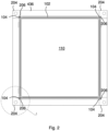
- Figure 2 depicts a top view of a semipermeable membrane 110 with a sealing 102 upon an end plate 436 of the stack plate device 400 according to an embodiment of the invention.
- the semipermeable layer 110 is provided with a circumferential sealing 102.
- the sealing 102 comprises at least one radial protrusion 104 per mounting profile 204.
- the protrusions 104 are pressed sealingly into recesses 206 of the mounting profiles 204 on the end plate 436. in an intended mounting position of the semipermeable layer 110.
- Figure 3 depicts a detailed view of the semipermeable membrane 110 with the sealing 102 during the mounting process, where the semipermeable layer 110 is not yet positioned in the intended mounting position at the mounting profile 204.
- Figure 4 shows the semipermeable membrane 110 in an end position.
- the protrusion 104 comprises two legs 106 which are pressed together when the protrusion 104 is pressed sealingly into the recess 206 of the mounting profile 204.
- the protrusion 104 seals the different sides of the stack plate device 400 against the mounting profile 204.
- the mounting profile 204 is provided with a center hole 209 for attaching the mounting profile 204 to the end plate 436 by a screw.
- the protrusion 104 may be provided with a trapezoidal cross-section, for fitting sealingly into the recess 206.
- the recess 206 of the mounting profile 204 is provided with an opening angle 207.
- the opening angle 207 may be at least 60°, in particular 90°.
- the opening angle 207 is 90°, which may be easy for manufacturing, appropriate for mounting the semipermeable layer 110 and also provides an effective sealing of the protrusion 104.
- the semipermeable layer 110 may be overmolded with the sealing 102.
- a durable connection of the sealing 102 and the semipermeable layer 110 can be provided.
- easy mounting of the semipermeable layer 110 with the sealing may be achieved.
- Figure 5 depicts an isometric view of part of a number of stack plates 100 stacked on top of each other, according to an embodiment of the invention, whereas in Figure 6 a detailed view of the number of stack plates 100 stacked on top of each other is shown.
- Figure 7 an exploded view of the number of stack plates 100 is shown, whereas in Figure 8 a detailed view of the exploded view according to Figure 7 is depicted.
- the number of stack plates 100 and semipermeable layers 110 are stacked on an end plate 436.
- the stack plates 100 and the semipermeable membranes 110 are stacked alternately on top of each other in a stacking direction 500. Successive stack plates 100 are stacked with inflow regions 210, 220 transverse to each other. Inflow regions 210, 220 of second nearest stack plates 100 are positioned on the same side of the stack.
- Successive stack plates 100 are connected to one another in a fluid-tight manner except for inflow or outflow regions 210, 212; 220, 222 between the stack plates 100.
- Successive stack plates 100 are sealed by the sealing 102 of the semipermeable layer 110 at the frames 120 (see Figures 7 and 8 ) of the stack plates 100.
- the stack plate 100 comprises a peripheral frame 120 which encloses a through-opening 130 in the stack plate 100.
- the through-opening 130 is covered by the semipermeable layer 110, which is stacked beneath or above the stack plate 100.
- the through-opening 130 is reinforced by stiffening members 136 which may support the highly flexible membrane of the semipermeable layer 110 against the pressure of the flowing fluids.
- the frame 120 of the stack plate 100 is provided with spacers 138 on two opposing longitudinal sides 114, 116.
- the spacers 138 comprise a plurality of openings 140 for inflow or outflow of the first or the second fluid.
- the frame 120 is a metal frame, wherein the spacers 138 are bent lugs 142. In the bent lugs 142 the openings 140 are clearly to be seen.
- nubs 134 are arranged in the frame 120 of the stack plate 100 for positioning of a turbulence generating component 154 (not shown) onto the stack plate 100.
- the nubs 134 may be provided by stamping the frame 120 of the stack plate 100.
- the nubs 134 provide a reproducible positioning of the turbulence generating component 154, e.g. a grid.
- At least one turbulence generating component 154, in particular a grid component, may be arranged on a first side 126 and/or a second side 125 of the stack plates 100.
- the frame 120 is a plastics frame.
- the spacers 138 are in one piece with the frame 120 and may be made in one manufacturing process.
- the spacers 138 also are provided with a plurality of openings 140 for fluid flow.
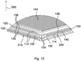
- Figure 11 depicts an isometric view of part of a number of stack plates 100 stacked on top of each other, according to a further embodiment of the invention, whereas in Figure 12 a detailed view of the number of stack plates 100 is shown.
- a turbulence generating component 154 in particular a grid component, is to be seen on the top side of the stack plates 100.
- the stack plate 100 is overmolded with the turbulence generating component 154.
- the turbulence generating component 154 may be made from the same material as the frame 120.
- the turbulence generating component 154 may be an insert in an injection molding process of the stack plate 100.
- Figure 13 depicts a humidifier 1000 for a fuel cell system according to an embodiment of the invention, in an isometric view.
- the humidifier 1000 comprises a stack plate device 400, having a plurality of stack plates 100, as shown in Figure 1 .
- the stack plates 100 are stacked one on top of each other in a stacking direction 500, and are enclosed on both ends 430, 432 of the stacking direction 500 by end plates 436.
- the stack of stack plates 100 is enclosed parallel to the stacking direction 500 by mounting profiles 204.
- a side cover 1012 with an inlet 1004 for a first fluid 600, in particular an exhaust gas of the fuel cell system, a side cover 1014 with an inlet 1008 for a second fluid 602, in particular a supply air of the fuel cell system, and respective side covers with an outlet 1006 for the first fluid 600 and an outlet 1010 for the second fluid 602 are mounted sealingly to the mounting profiles 204 and the end plates 436 of the stack plate device 400.
- the stack plate device 400 is provided with sealed inputs 1004, 1008 and outputs 1006, 1010 for the two fluids.
- At least first and second groups of flow channels 410, 420 are formed in the stack plate device 400 for fluid flow transversely to one another on sides 125, 126 of the stack plates 100 and are separated by semipermeable layers 110, in particular moisture-permeable layers 110.
- the first group of flow channels 410 is arranged between the inlet 1004 and the outlet 1006 for the first fluid 600 and the second group of flow channels 420 is arranged between the inlet 1008 and the outlet 1010 for the second fluid 602.
- the semipermeable layer 110 is provided with a circumferential sealing 102.
- the sealing 102 comprises at least one radial protrusion 104 per mounting profile 204.
- the protrusions 104 are pressed sealingly into recesses 206 of the mounting profiles 204 in an intended mounting position of the semipermeable layer 110.
Landscapes
- Chemical & Material Sciences (AREA)
- Chemical Kinetics & Catalysis (AREA)
- Life Sciences & Earth Sciences (AREA)
- Engineering & Computer Science (AREA)
- Manufacturing & Machinery (AREA)
- Sustainable Development (AREA)
- Sustainable Energy (AREA)
- Electrochemistry (AREA)
- General Chemical & Material Sciences (AREA)
- Fuel Cell (AREA)
Abstract
A stack plate device (400) for a humidifier (1000) includes a stack of stack plates (100) being stacked on top of each other in a stacking direction (500), end plates (436) pressing together the stack plates (100) or both ends (430, 432) of the stack by end plates (436), and mounting profiles (204) enclosing the stack of the stack plates (100) in the stacking direction (500), and comprising recesses (206). The stack plate device (400) further includes semipermeable layers (110) separating first and second groups of flow channels (410, 420) and comprising a circumferential sealing (102) comprising at least one radial protrusion (104) per each of the mounting profiles (204), the at least one radial protrusion (104) being pressed sealingly into the recesses (206) in an intended mounting position of the semipermeable layer (110).
Description
- The invention relates to a stack plate device for a humidifier, in particular for a fuel cell system, as well as a humidifier for a fuel cell system.
- Humidifiers are used for example to humidify process gas for fuel cells which are operated with molecular hydrogen and/or oxygen or air for electricity generation. The process gases supplied to the fuel cell are for this reason usually set to a desired, stable humidity in a humidifier. A humidifier comprises flow plates which are usually provided with channel structures, wherein the channels adjoin a water transfer medium, typically in the form of a semipermeable layer such as a water-transfer membrane. An assembly usually provides a plurality of flow plates, between which there are arranged water transfer membranes.
- For example, on one side of a semipermeable layer a moist gas, e.g. an exhaust gas from the fuel cell, is guided through the channels of an adjacent flow plate, and on the opposite side of the semipermeable layer a dry gas, e.g. fresh air, is passed through channels of a second flow plate. In this case, the moist gas on one side of the semipermeable layer gives off moisture to the semipermeable layer, whereas on the opposite side the semipermeable layer gives off moisture to the dry gas.
- A humidifier is disclosed in
US 9,680,169 B2 - A further humidifier is disclosed in
US 9,859,575 B2 - It is an object of the invention to provide a stack plate device for a humidifier, in particular for a fuel cell system, with improved manufacturing properties.
- Another object is to provide a humidifier with a stack plate device with improved manufacturing properties.
- According to an aspect of the invention, the object is achieved by a stack plate device for a humidifier, in particular for a fuel cell system, having a stack of a plurality of stack plates, the stack plates being stacked on top of each other in a stacking direction, and being pressed together on both ends of the stack by end plates, the stack of stack plates is enclosed parallel to the stacking direction by mounting profiles, wherein at least first and second groups of flow channels are formed in the stack plate device for fluid flow transversely to one another on opposing sides of the stack plates and being separated by semipermeable layers, in particular moisture-permeable layers, wherein the semipermeable layer is provided with a circumferential sealing, the sealing comprising at least one radial protrusion per mounting profile, the protrusion being pressed sealingly into recesses of the mounting profiles in an intended mounting position of the semipermeable layer.
- According to a further aspect of the invention, the further object is achieved by a humidifier for a fuel cell system, comprising at least one inlet for a first fluid, in particular an exhaust gas of the fuel cell system, an inlet for a second fluid, in particular a supply air of the fuel cell system, an outlet for the first fluid and an outlet for the second fluid, further comprising a stack plate device according to any one of the preceding claims, having a plurality of stack plates, the stack plates being stacked on top of each other in a stacking direction, and being enclosed on both ends of the stacking direction by end plates, the stack of stack plates being enclosed parallel to the stacking direction by mounting profiles, wherein at least first and second groups of flow channels are formed in the stack plate device for fluid flow transversely to one another on sides of the stack plates and being separated by semipermeable layers, in particular moisture-permeable layers, wherein the first group of flow channels is arranged between the inlet and the outlet for the first fluid and the second group of flow channels is arranged between the inlet and the outlet for the second fluid, wherein the semipermeable layer is provided with a circumferential sealing, the sealing comprising at least one radial protrusion per mounting profile, the protrusion being pressed sealingly into recesses of the mounting profiles in an intended mounting position of the semipermeable layer.
- Advantageous embodiments are described in the dependent claims, the description and the drawings.
- According to an aspect of the invention, a stack plate device for a humidifier, in particular for a fuel cell system, is proposed, having a stack of a plurality of stack plates, the stack plates being stacked on top of each other in a stacking direction, and being pressed together on both ends of the stack by end plates, the stack of stack plates is enclosed parallel to the stacking direction by mounting profiles. At least first and second groups of flow channels are formed in the stack plate device for fluid flow transversely to one another on opposing sides of the stack plates and being separated by semipermeable layers, in particular moisture-permeable layers. The semipermeable layer is provided with a circumferential sealing, the sealing comprising at least one radial protrusion per mounting profile, the protrusion being pressed sealingly into recesses of the mounting profiles in an intended mounting position of the semipermeable layer.
- Favorably, the plurality of stack plates and semipermeable layers with the sealing may be stacked alternatingly on top of each other for manufacturing the stack plate device. The stack plates and the semipermeable layers are stacked between the mounting profiles wherein the stack plates and the semipermeable layers may be positioned according to a forced guiding concept. The protrusions of the sealing are guided to the recesses of the mounting profiles. In an end position of the semipermeable layer the protrusions are pressed into the recesses, thus sealing favorably one side of the stack plate device against another side of the stack plate device in an intended use in a humidifier. The protrusions are shaped in a way that the protrusions of successive semipermeable layers connect to each other, thus achieving in a continuous sealing along the recess of a mounting profile.
- Advantageously, an easy and cost-effective manufacturing concept of the stack plate device can be realized. The stack device may be sealed in a humidifier by the proposed sealing without the need for gluing or foaming and curing. Also sealing materials which must be cured after joining may be avoided. Thus automatized manufacturing of the stack plate device is possible. The stack plate device may be a precursor of classical manufacturing processes. This results in a reliable solution for elastic joint sealing if elastomers are chosen appropriately.
- Three of the alternatingly successive stack plates each form two of the flow channels, which are formed such that flow can pass through them transversely to one another on opposing sides of the stack plates.
- The semipermeable layer separates the exhaust gas flow channel from the supply air flow channel. The semipermeable layer can be designed, for example, as a PFSA (perfluorosulfonic acid) membrane. Such membranes are also commonly used as proton exchange membranes. The membrane is airtight but permeable to moisture.
- According to a favorable embodiment of the stack plate device, the protrusion may comprise two legs being pressed together when being pressed sealingly into the recess of the mounting profile. Thus, there is enough flexibility in the protrusion for proper sealing against walls of the recess when positioning the semipermeable layer between the mounting profiles.
- According to a favorable embodiment of the stack plate device, the protrusion may be provided with a trapezoidal cross-section. Advantageously, a proper sealing against the recess may be achieved when the semipermeable layer is positioned in an end position between the mounting profiles.
- According to a favorable embodiment of the stack plate device, the recess of the mounting profile may be provided with an opening angle, the opening angle being at least 60°, in particular being 90°. Advantageously, a proper sealing against the recess may be achieved when the semipermeable layer is positioned in an end position between the mounting profiles.
- According to a favorable embodiment of the stack plate device, the semipermeable layer may be overmolded with the sealing. By this way, the sealing may be connected to the semipermeable layer in an enduring manner. Thus, cost effective manufacturing of the semipermeable layer may be achieved.
- According to a favorable embodiment of the stack plate device, the stack plate may comprise a peripheral frame which encloses a through-opening in the stack plate, the through-opening being covered by the semipermeable layer. In particular, the through-opening may be reinforced by stiffening members. Thus, the stacked stack plates offer enough free space for free flowing of the first and second fluid on alternating sides of the stack plates. By the through-opening an efficient moisture transfer through the semipermeable layer may be achieved wherein the two fluids are kept separate by the semipermeable layer.
- According to a favorable embodiment of the stack plate device, the frame may be provided with spacers on two opposing longitudinal sides, wherein the spacers may comprise a plurality of openings for inflow or outflow of the first or the second fluid. By this way, the spacers keep a fixed distance between the stacked stack plates. The opening allow the first and second fluid to flow between the stack plates appropriately.
- According to a favorable embodiment of the stack plate device, the frame may be a metal frame, wherein the spacers may be bent lugs. Thus, easy and cost-effective manufacturing of the stack plates may be achieved. The stack plates can preferably be made from stainless steel because of advantageous flexible properties for stacking.
- According to a favorable embodiment of the stack plate device, the frame may be a plastics frame, wherein the spacers may be in one piece with the frame. Thus, easy and cost-effective manufacturing of the stack plates may be achieved. The stack plates can preferably be formed from plastic, for example PA6.6 (polyamide), PPA (polyphtalamide), PPS (polyphenylene sulfide), or TPX (polymethylpentene).
- According to a favorable embodiment of the stack plate device, at least one turbulence generating component, in particular a grid component, may be arranged on a first side and/or a second side of the stack plates. The turbulence generating components may be arranged on the stack plate and may support the semipermeable layer and also regulate the fluid flow for optimized mass transfer through the semipermeable layer. Height, angle and spacing of struts of the turbulence generating component can vary if necessary. The turbulence generating component may be made from plastics, e.g. PPS, or from stainless steel, e.g., for a stable support. The grid-like support element can be attached to the frame of the stack plate in a shape adapted to the frame.
- According to a favorable embodiment of the stack plate device, nubs may be arranged in the frame of the stack plate for positioning of the turbulence generating component onto the stack plate. Thus, the grid-like support element can be attached to the frame of the stack plate in a reproducible position.
- According to a favorable embodiment of the stack plate device, the stack plate may be overmolded with the turbulence generating component. In particular, if the stack plate is made from plastics, the turbulence generating component can be integrated during the molding process of the stack plate and thus be connected to the frame of the stack plate in a durable way.
- According to a favorable embodiment of the stack plate device, the stack plates and the semipermeable membranes may be stacked alternately on top of each other in a stacking direction, wherein successive stack plates may be stacked with inflow regions transverse to each other, and wherein inflow regions of second nearest stack plates may be positioned on the same side of the stack. Thus, three each of the alternately successive stack plates form a first and a second group of flow channels formed transversely to each other for flow of the first or second fluid therethrough. The first group of flow channels are arranged between the inlet and the outlet for the first fluid and the second group of flow channels are arranged between the inlet and the outlet for the second fluid.
- According to a favorable embodiment of the stack plate device, successive stack plates may be connected to one another in a fluid-tight manner except for inflow or outflow regions between the stack plates. In particular, successive stack plates may be sealed by the sealing of the semipermeable layer at the frames of the stack plates. By this way the flow channels may advantageously be sealed one against each other in the frame region in order to guarantee steady flow conditions for the exhaust gas and the supply air. Favorable humidity transfer through the semipermeable layer may be provided.
- According to a further aspect of the invention, a humidifier for a fuel cell system may be proposed, comprising at least one inlet for a first fluid, in particular an exhaust gas of the fuel cell system, an inlet for a second fluid, in particular a supply air of the fuel cell system, an outlet for the first fluid and an outlet for the second fluid. Further the humidifier comprises a stack plate device, having a plurality of stack plates, the stack plates being stacked on top of each other in a stacking direction, and being enclosed on both ends of the stacking direction by end plates, the stack of stack plates being enclosed parallel to the stacking direction by mounting profiles. At least first and second groups of flow channels are formed in the stack plate device for fluid flow transversely to one another on sides of the stack plates and being separated by semipermeable layers, in particular moisture-permeable layers. The first group of flow channels is arranged between the inlet and the outlet for the first fluid and the second group of flow channels is arranged between the inlet and the outlet for the second fluid. The semipermeable layer is provided with a circumferential sealing, the sealing comprising at least one radial protrusion per mounting profile, the protrusions being pressed sealingly into recesses of the mounting profiles in an intended mounting position of the semipermeable layer.
- The humidifier represents a special embodiment of a flat membrane humidifier. A first, moist or water-rich fluid, for example exhaust gas from fuel cells, flows in one group of flow channels, while a second, dry fluid, for example supply air for the fuel cells, flows in another group of flow channels. The second dry fluid can be moistened by the first fluid via the semipermeable membranes.
- The first and second fluid, e.g. the exhaust gas and the supply air, may be fed to the stack plate device by the inlets and the outlets which are integrated in corresponding side covers attached to the mounting profiles of the stack plates device in a sealingly tight manner. The end plates of the stack plate device serve as a further cover, where the side covers may also be connected to. Advantageously, the humidifier does not need an additional housing, thus reducing the manufacturing costs of the humidifier significantly.
- The present invention together with the above-mentioned and other objects and advantages may best be understood from the following detailed description of the embodiments, but not restricted to the embodiments.
-
Figure 1 shows a stack plate device for a humidifier, in particular a humidifier for a fuel cell system, according to an embodiment of the invention, in an isometric view. -
Figure 2 is a top view of a semipermeable layer with a sealing upon an end plate of the stack plate device according to an embodiment of the invention. -
Figure 3 is a detailed view of the semipermeable layer with a sealing according toFigure 2 during mounting. -
Figure 4 is a detailed view of the semipermeable layer with a sealing according toFigure 3 in an end position. -
Figure 5 is an isometric view of part of a number of stack plates stacked on top of each other, according to an embodiment of the invention. -
Figure 6 is a detailed view of the number of stack plates stacked on top of each other, according toFigure 5 . -
Figure 7 is an exploded view of the number of stack plates stacked on top of each other, according toFigure 5 . -
Figure 8 is a detailed view of the number of stack plates stacked on top of each other, according toFigure 7 . -
Figure 9 is an isometric view of part of a number of stack plates stacked on top of each other, according to a further embodiment of the invention. -
Figure 10 is a detailed view of the number of stack plates stacked on top of each other, according toFigure 9 . -
Figure 11 is an isometric view of part of a number of stack plates stacked on top of each other, according to a further embodiment of the invention. -
Figure 12 is a detailed view of the number of stack plates stacked on top of each other, according toFigure 11 . -
Figure 13 shows a humidifier for a fuel cell system according to an embodiment of the invention, in an isometric view. - In the drawings, like elements are referred to with equal reference numerals. The drawings are merely schematic representations, not intended to portray specific parameters of the invention. Moreover, the drawings are intended to depict only typical embodiments of the invention and therefore should not be considered as limiting the scope of the invention.
-
Figure 1 depicts astack plate device 400 for ahumidifier 1000, in particular ahumidifier 1000 for a fuel cell system, according to an embodiment of the invention, in an isometric view. - The
stack plate device 400 has a stack of a plurality ofstack plates 100. Thestack plates 100 are stacked on top of each other in a stackingdirection 500, and are pressed together on both ends 430, 432 of the stack byend plates 436. The stack ofstack plates 100 is enclosed parallel to the stackingdirection 500 by mountingprofiles 204. - At least first and second groups of
flow channels stack plate device 400 for fluid flow transversely to one another on opposingsides 125, 126 (Figure 8 ) of thestack plates 100. The first and second groups offlow channels semipermeable layers 110, in particular moisture-permeable layers 110. - Three of the alternatingly
successive stack plates 100 each forms two of theflow channels sides stack plates 100. - in
Figure 1 an ingoingfirst fluid flow 600 into theflow channels 410 throughinflow regions 210 ofstack plates 100 is shown and an ingoingsecond fluid flow 602 into theflow channels 420 throughinflow regions 210 ofstack plates 100. The outgoing fluid flows 600, 602 exit the stack ofstack plates 100 on the opposing sides.Corresponding outflow regions - The stack of
stack plates 100 andsemipermeable layers 110 is pressed together by twoend plates 436 on both ends 430, 432. Theend plates 436 are connected to the mountingprofiles 204 byscrews 208. -
Figure 2 depicts a top view of asemipermeable membrane 110 with a sealing 102 upon anend plate 436 of thestack plate device 400 according to an embodiment of the invention. - The
semipermeable layer 110 is provided with acircumferential sealing 102. The sealing 102 comprises at least oneradial protrusion 104 per mountingprofile 204. Theprotrusions 104 are pressed sealingly intorecesses 206 of the mountingprofiles 204 on theend plate 436. in an intended mounting position of thesemipermeable layer 110. -
Figure 3 depicts a detailed view of thesemipermeable membrane 110 with the sealing 102 during the mounting process, where thesemipermeable layer 110 is not yet positioned in the intended mounting position at the mountingprofile 204.Figure 4 shows thesemipermeable membrane 110 in an end position. - As may be seen, the
protrusion 104 comprises twolegs 106 which are pressed together when theprotrusion 104 is pressed sealingly into therecess 206 of the mountingprofile 204. Thus, theprotrusion 104 seals the different sides of thestack plate device 400 against the mountingprofile 204. The mountingprofile 204 is provided with acenter hole 209 for attaching the mountingprofile 204 to theend plate 436 by a screw. - Alternatively, the
protrusion 104 may be provided with a trapezoidal cross-section, for fitting sealingly into therecess 206. - The
recess 206 of the mountingprofile 204 is provided with anopening angle 207. Advantageously, theopening angle 207 may be at least 60°, in particular 90°. In the embodiment shown, theopening angle 207 is 90°, which may be easy for manufacturing, appropriate for mounting thesemipermeable layer 110 and also provides an effective sealing of theprotrusion 104. - Favorably, the
semipermeable layer 110 may be overmolded with the sealing 102. Thus, a durable connection of the sealing 102 and thesemipermeable layer 110 can be provided. Also, easy mounting of thesemipermeable layer 110 with the sealing may be achieved. -
Figure 5 depicts an isometric view of part of a number ofstack plates 100 stacked on top of each other, according to an embodiment of the invention, whereas inFigure 6 a detailed view of the number ofstack plates 100 stacked on top of each other is shown. InFigure 7 an exploded view of the number ofstack plates 100 is shown, whereas inFigure 8 a detailed view of the exploded view according toFigure 7 is depicted. - The number of
stack plates 100 andsemipermeable layers 110 are stacked on anend plate 436. - The
stack plates 100 and thesemipermeable membranes 110 are stacked alternately on top of each other in a stackingdirection 500.Successive stack plates 100 are stacked withinflow regions Inflow regions nearest stack plates 100 are positioned on the same side of the stack. -
Successive stack plates 100 are connected to one another in a fluid-tight manner except for inflow oroutflow regions stack plates 100.Successive stack plates 100 are sealed by the sealing 102 of thesemipermeable layer 110 at the frames 120 (seeFigures 7 and8 ) of thestack plates 100. - As in particular may be seen from
Figures 7 and8 , thestack plate 100 comprises aperipheral frame 120 which encloses a through-opening 130 in thestack plate 100. The through-opening 130 is covered by thesemipermeable layer 110, which is stacked beneath or above thestack plate 100. The through-opening 130 is reinforced by stiffeningmembers 136 which may support the highly flexible membrane of thesemipermeable layer 110 against the pressure of the flowing fluids. - The
frame 120 of thestack plate 100 is provided withspacers 138 on two opposinglongitudinal sides spacers 138 comprise a plurality ofopenings 140 for inflow or outflow of the first or the second fluid. - In the embodiment shown in
Figures 5 to 8 , theframe 120 is a metal frame, wherein thespacers 138 are bent lugs 142. In the bent lugs 142 theopenings 140 are clearly to be seen. - In
Figure 6 the alternating order ofstack plates 100 andsemipermeable layers 110 in the stack is to be seen. Theprotrusions 104 of thesealings 102 are formed in a way that the successive order of theprotrusions 104 of thesealings 102 of the differentsemipermeable layers 110 provides a continuous sealing contour when being positioned in therecess 206 of a mountingprofile 204. - in the embodiment shown in
Figures 7 and8 nubs 134 are arranged in theframe 120 of thestack plate 100 for positioning of a turbulence generating component 154 (not shown) onto thestack plate 100. Thenubs 134 may be provided by stamping theframe 120 of thestack plate 100. Thenubs 134 provide a reproducible positioning of theturbulence generating component 154, e.g. a grid. At least oneturbulence generating component 154, in particular a grid component, may be arranged on afirst side 126 and/or asecond side 125 of thestack plates 100. - in
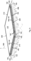
Figure 9 an isometric view of part of a number ofstack plates 100 stacked on top of each other, according to a further embodiment of the invention is depicted, whereas inFigure 10 a detailed view of the number ofstack plates 100 is shown. - in this embodiment the
frame 120 is a plastics frame. Thespacers 138 are in one piece with theframe 120 and may be made in one manufacturing process. Thespacers 138 also are provided with a plurality ofopenings 140 for fluid flow. -
Figure 11 depicts an isometric view of part of a number ofstack plates 100 stacked on top of each other, according to a further embodiment of the invention, whereas inFigure 12 a detailed view of the number ofstack plates 100 is shown. - in this embodiment a
turbulence generating component 154, in particular a grid component, is to be seen on the top side of thestack plates 100. in contrary to other embodiments, whereturbulence generating components 154 are laid on thestack plates 100 as separate components, in this embodiment shown, thestack plate 100 is overmolded with theturbulence generating component 154. This is possible with a plastic frame. Theturbulence generating component 154 may be made from the same material as theframe 120. Alternatively theturbulence generating component 154 may be an insert in an injection molding process of thestack plate 100. -
Figure 13 depicts ahumidifier 1000 for a fuel cell system according to an embodiment of the invention, in an isometric view. - The
humidifier 1000 comprises astack plate device 400, having a plurality ofstack plates 100, as shown inFigure 1 . Thestack plates 100 are stacked one on top of each other in a stackingdirection 500, and are enclosed on both ends 430, 432 of the stackingdirection 500 byend plates 436. The stack ofstack plates 100 is enclosed parallel to the stackingdirection 500 by mountingprofiles 204. - A
side cover 1012 with aninlet 1004 for afirst fluid 600, in particular an exhaust gas of the fuel cell system, aside cover 1014 with aninlet 1008 for asecond fluid 602, in particular a supply air of the fuel cell system, and respective side covers with anoutlet 1006 for thefirst fluid 600 and anoutlet 1010 for thesecond fluid 602 are mounted sealingly to the mountingprofiles 204 and theend plates 436 of thestack plate device 400. Thus, thestack plate device 400 is provided with sealedinputs outputs - At least first and second groups of
flow channels stack plate device 400 for fluid flow transversely to one another onsides stack plates 100 and are separated bysemipermeable layers 110, in particular moisture-permeable layers 110. - The first group of
flow channels 410 is arranged between theinlet 1004 and theoutlet 1006 for thefirst fluid 600 and the second group offlow channels 420 is arranged between theinlet 1008 and theoutlet 1010 for thesecond fluid 602. - The
semipermeable layer 110 is provided with acircumferential sealing 102. The sealing 102 comprises at least oneradial protrusion 104 per mountingprofile 204. Theprotrusions 104 are pressed sealingly intorecesses 206 of the mountingprofiles 204 in an intended mounting position of thesemipermeable layer 110. By this way, the two fluids are provided with separate fluid flows inside thehumidifier 1000, advantageously sealed against each other. -
- 100 stack plate
- 102 sealing
- 104 protrusion element
- 106 leg
- 110 semipermeable layer
- 114 longitudinal side
- 116 longitudinal side
- 120 frame
- 125 second side, bottom side
- 126 first side, top side
- 130 through-opening
- 134 nub
- 136 stiffening member
- 138 spacer
- 140 opening
- 142 bent lug
- 154 turbulence generating component
- 204 mounting profile
- 206 recess
- 207 opening angle
- 208 screw
- 209 hole
- 210 inflow region
- 212 outflow region
- 220 inflow region
- 222 outflow region
- 400 stack plate device
- 410 flow channel
- 420 flow channel
- 430 end
- 432 end
- 436 end plate
- 500 stacking direction
- 600 first fluid (exhaust gas)
- 602 second fluid (supply air)
- 1000 humidifier
- 1003 housing cover
- 1004 inlet first fluid
- 1006 outlet first fluid
- 1008 inlet second fluid
- 1010 outlet second fluid
- 1012 side cover
- 1014 side cover
Claims (15)
- A stack plate device (400) for a humidifier (1000), the stack plate device (400) comprising:a stack of stack plates (100) being stacked on top of each other in a stacking direction (500);end plates (436) pressing together the stack plates (100) on both ends (430, 432) of the stack by end plates (436);mounting profiles (204) enclosing the stack of the stack plates (100) in the stacking direction (500), and comprising recesses (206),wherein first and second groups of flow channels (410, 420) are formed in the stack plate device (400) for fluid flow transversely to one another on opposing sides (125, 126) of the stack plates (100); andsemipermeable layers (110) separating the first and second groups of flow channels (410, 420) and comprising a circumferential sealing (102) comprising at least one radial protrusion (104) per each of the mounting profiles (204), the at least one radial protrusion (104) being pressed sealingly into the recesses (206) in an intended mounting position of the semipermeable layer (110).
- The stack plate device (400) according to claim 1, wherein any one of the at least one radial protrusion (104) comprises two legs (106) being pressed together when being pressed sealingly into a respective one of the recesses (206) of the mounting profiles (204).
- The stack plate device (400) according to any one of the preceding claims, wherein any one of the at least one radial protrusion (104) has a trapezoidal cross-section.
- The stack plate device (400) according to any one of the preceding claims, wherein any one of the recesses (206) of the mounting profiles (204) has an opening angle (207) of at least 60°.
- The stack plate device (400) according to any one of the preceding claims, wherein any one of the semipermeable layers (110) is overmolded with the circumferential sealing (102).
- The stack plate device (400) according to any one of the preceding claims, wherein any one of the stack plates (100) comprises:a peripheral frame (120) enclosing a through-opening (130) in the any one of the stack plates (100), the through-opening (130) being covered by a respective one of the semipermeable layers (110); andstiffening members (136) reinforcing the through-opening (130).
- The stack plate device (400) according to claim 6, wherein the peripheral frame (120) comprises spacers (138) on two opposing longitudinal sides (114, 116), the spacers (138) comprising openings (140) for inflow or outflow of the fluid flow.
- The stack plate device (400) according to claim 7, wherein the peripheral frame (120) is a metal frame, and
the spacers (138) are bent lugs (142). - The stack plate device (400) according to claim 7, wherein the peripheral frame (120) is a plastic frame, and
the spacers (138) are in one piece with the peripheral frame (120). - The stack plate device (400) according to claim 6, further comprising at least one turbulence generating component (154) arranged on either one or both of the opposing sides (125, 126) of a respective one of the stack plates (100).
- The stack plate device (400) according to claim 10, wherein the peripheral frame (120) comprises nubs (134) for positioning of the at least one turbulence generating component (154) onto the respective one of the stack plates (100).
- The stack plate device (400) according to claim 10, wherein the respective one of the stack plates (100) is overmolded with the at least one turbulence generating component (154).
- The stack plate device (400) according to any one of the preceding claims, wherein the stack plates (100) and the semipermeable layers (110) are stacked alternately on top of each other in the stacking direction (500),
successive ones of the stack plates (100) are stacked with inflow regions (210, 220) transverse to each other, the inflow regions (210, 220) of second nearest ones of the stack plates (100) being positioned on a same side of the stack. - The stack plate device (400) according to any one of the preceding claims, wherein successive ones of the stack plates (100) are connected to one another in a fluid-tight manner except for inflow or outflow regions (210, 212; 220, 222) between the stack plates (100), and
the successive ones of the stack plates (100) are sealed by the circumferential sealing (102) of a respective one of the semipermeable layers (110) at peripheral frames (120) of the stack plates (100). - A humidifier (1000) for a fuel cell system, the humidifier (1000) comprising:at least one inlet (1004) for a first fluid (600);an inlet (1008) for a second fluid (602);an outlet (1006) for the first fluid (600);an outlet (1010) for the second fluid (602); andthe stack plate device (400) according to any one of the preceding claims,wherein the first group of flow channels (410) is arranged between the inlet (1004) and the outlet (1006) for the first fluid (600), andthe second group of flow channels (420) is arranged between the inlet (1008) and the outlet (1010) for the second fluid (602).
Priority Applications (1)
| Application Number | Priority Date | Filing Date | Title |
|---|---|---|---|
| EP23193072.8A EP4512512A1 (en) | 2023-08-24 | 2023-08-24 | Stack plate device and humidifier for a fuel cell system |
Applications Claiming Priority (1)
| Application Number | Priority Date | Filing Date | Title |
|---|---|---|---|
| EP23193072.8A EP4512512A1 (en) | 2023-08-24 | 2023-08-24 | Stack plate device and humidifier for a fuel cell system |
Publications (1)
| Publication Number | Publication Date |
|---|---|
| EP4512512A1 true EP4512512A1 (en) | 2025-02-26 |
Family
ID=87801120
Family Applications (1)
| Application Number | Title | Priority Date | Filing Date |
|---|---|---|---|
| EP23193072.8A Pending EP4512512A1 (en) | 2023-08-24 | 2023-08-24 | Stack plate device and humidifier for a fuel cell system |
Country Status (1)
| Country | Link |
|---|---|
| EP (1) | EP4512512A1 (en) |
Citations (7)
| Publication number | Priority date | Publication date | Assignee | Title |
|---|---|---|---|---|
| US20150162627A1 (en) * | 2013-12-11 | 2015-06-11 | Mann+Hummel Gmbh | Humidifier, in Particular for a Fuel Cell |
| US9680169B2 (en) | 2012-08-30 | 2017-06-13 | Mann+Hummel Gmbh | Humidification device, in particular for a fuel cell |
| US20190260044A1 (en) * | 2016-09-23 | 2019-08-22 | Reinz-Dichtungs-Gmbh | Flow plate for a humidifier |
| US20210391586A1 (en) * | 2020-06-15 | 2021-12-16 | Mahle International Gmbh | Membrane assembly for a humidification device |
| WO2022002582A1 (en) * | 2020-06-29 | 2022-01-06 | Mahle International Gmbh | Humidifier and a method for the sealing thereof |
| EP4000720A1 (en) * | 2020-11-19 | 2022-05-25 | MAHLE International GmbH | Humidifier |
| US20230018380A1 (en) * | 2021-07-13 | 2023-01-19 | Mahle International Gmbh | Humidifier |
-
2023
- 2023-08-24 EP EP23193072.8A patent/EP4512512A1/en active Pending
Patent Citations (8)
| Publication number | Priority date | Publication date | Assignee | Title |
|---|---|---|---|---|
| US9680169B2 (en) | 2012-08-30 | 2017-06-13 | Mann+Hummel Gmbh | Humidification device, in particular for a fuel cell |
| US20150162627A1 (en) * | 2013-12-11 | 2015-06-11 | Mann+Hummel Gmbh | Humidifier, in Particular for a Fuel Cell |
| US9859575B2 (en) | 2013-12-11 | 2018-01-02 | Mann+Hummel Gmbh | Humidifier, in particular for a fuel cell |
| US20190260044A1 (en) * | 2016-09-23 | 2019-08-22 | Reinz-Dichtungs-Gmbh | Flow plate for a humidifier |
| US20210391586A1 (en) * | 2020-06-15 | 2021-12-16 | Mahle International Gmbh | Membrane assembly for a humidification device |
| WO2022002582A1 (en) * | 2020-06-29 | 2022-01-06 | Mahle International Gmbh | Humidifier and a method for the sealing thereof |
| EP4000720A1 (en) * | 2020-11-19 | 2022-05-25 | MAHLE International GmbH | Humidifier |
| US20230018380A1 (en) * | 2021-07-13 | 2023-01-19 | Mahle International Gmbh | Humidifier |
Similar Documents
| Publication | Publication Date | Title |
|---|---|---|
| US20220181655A1 (en) | Fuel cell humidifier and packing member for same | |
| KR101269507B1 (en) | humidifying membrane module | |
| US20240145740A1 (en) | Humidifier comprising plate stack and plate stack | |
| WO2012094764A1 (en) | Humidifier for fuel cell systems | |
| US20240186542A1 (en) | Stack plate, stack plate device and humidifier | |
| US20240063408A1 (en) | Fuel cell membrane humidifier preventing damage of humidification membrane | |
| US20240021847A1 (en) | Fuel cell humidifier | |
| CN110035817B (en) | Membrane humidifiers preferred for fuel cell systems | |
| CN115088108B (en) | Gasket assembly and fuel cell humidifier including the same | |
| EP4421923A1 (en) | Stack plate and stack plate device for a humidifier | |
| US20250038231A1 (en) | Humidifier stack, humidifier device, and membrane for humidifier stack | |
| US20240291001A1 (en) | Flow plate and humidifier for fuel cell system | |
| CN117836050A (en) | Humidifier with channel plate, channel section plate for humidifier and channel plate | |
| WO2024022798A2 (en) | Stack of plates for a humidifier and humidifier | |
| US11870109B2 (en) | Gasket assembly and fuel cell humidifier including same | |
| JP7791962B2 (en) | Gasket assembly and fuel cell membrane humidifier including same | |
| EP4414057A1 (en) | Stack plate device and humidifier for fuel cell system | |
| US20240063409A1 (en) | Fuel cell membrane humidifier | |
| KR102926186B1 (en) | Fuel cell humidifier | |
| KR20220111057A (en) | Fuel cell humidifier | |
| KR102858667B1 (en) | Humidifier for Fuel Cell | |
| CN116868387A (en) | Gasket assembly and fuel cell membrane humidifier including the gasket assembly |
Legal Events
| Date | Code | Title | Description |
|---|---|---|---|
| PUAI | Public reference made under article 153(3) epc to a published international application that has entered the european phase |
Free format text: ORIGINAL CODE: 0009012 |
|
| STAA | Information on the status of an ep patent application or granted ep patent |
Free format text: STATUS: THE APPLICATION HAS BEEN PUBLISHED |
|
| AK | Designated contracting states |
Kind code of ref document: A1 Designated state(s): AL AT BE BG CH CY CZ DE DK EE ES FI FR GB GR HR HU IE IS IT LI LT LU LV MC ME MK MT NL NO PL PT RO RS SE SI SK SM TR |
|
| STAA | Information on the status of an ep patent application or granted ep patent |
Free format text: STATUS: REQUEST FOR EXAMINATION WAS MADE |
|
| 17P | Request for examination filed |
Effective date: 20250822 |