EP4512374A1 - Expandable trial femoral neck - Google Patents
Expandable trial femoral neck Download PDFInfo
- Publication number
- EP4512374A1 EP4512374A1 EP24195675.4A EP24195675A EP4512374A1 EP 4512374 A1 EP4512374 A1 EP 4512374A1 EP 24195675 A EP24195675 A EP 24195675A EP 4512374 A1 EP4512374 A1 EP 4512374A1
- Authority
- EP
- European Patent Office
- Prior art keywords
- nested
- neck
- threaded element
- telescoping
- head
- Prior art date
- Legal status (The legal status is an assumption and is not a legal conclusion. Google has not performed a legal analysis and makes no representation as to the accuracy of the status listed.)
- Pending
Links
Images



Classifications
-
- A—HUMAN NECESSITIES
- A61—MEDICAL OR VETERINARY SCIENCE; HYGIENE
- A61F—FILTERS IMPLANTABLE INTO BLOOD VESSELS; PROSTHESES; DEVICES PROVIDING PATENCY TO, OR PREVENTING COLLAPSING OF, TUBULAR STRUCTURES OF THE BODY, e.g. STENTS; ORTHOPAEDIC, NURSING OR CONTRACEPTIVE DEVICES; FOMENTATION; TREATMENT OR PROTECTION OF EYES OR EARS; BANDAGES, DRESSINGS OR ABSORBENT PADS; FIRST-AID KITS
- A61F2/00—Filters implantable into blood vessels; Prostheses, i.e. artificial substitutes or replacements for parts of the body; Appliances for connecting them with the body; Devices providing patency to, or preventing collapsing of, tubular structures of the body, e.g. stents
- A61F2/02—Prostheses implantable into the body
- A61F2/30—Joints
- A61F2/32—Joints for the hip
- A61F2/36—Femoral heads ; Femoral endoprostheses
- A61F2/3609—Femoral heads or necks; Connections of endoprosthetic heads or necks to endoprosthetic femoral shafts
-
- A—HUMAN NECESSITIES
- A61—MEDICAL OR VETERINARY SCIENCE; HYGIENE
- A61F—FILTERS IMPLANTABLE INTO BLOOD VESSELS; PROSTHESES; DEVICES PROVIDING PATENCY TO, OR PREVENTING COLLAPSING OF, TUBULAR STRUCTURES OF THE BODY, e.g. STENTS; ORTHOPAEDIC, NURSING OR CONTRACEPTIVE DEVICES; FOMENTATION; TREATMENT OR PROTECTION OF EYES OR EARS; BANDAGES, DRESSINGS OR ABSORBENT PADS; FIRST-AID KITS
- A61F2/00—Filters implantable into blood vessels; Prostheses, i.e. artificial substitutes or replacements for parts of the body; Appliances for connecting them with the body; Devices providing patency to, or preventing collapsing of, tubular structures of the body, e.g. stents
- A61F2/02—Prostheses implantable into the body
- A61F2/30—Joints
- A61F2/32—Joints for the hip
- A61F2/36—Femoral heads ; Femoral endoprostheses
- A61F2/3662—Femoral shafts
-
- A—HUMAN NECESSITIES
- A61—MEDICAL OR VETERINARY SCIENCE; HYGIENE
- A61F—FILTERS IMPLANTABLE INTO BLOOD VESSELS; PROSTHESES; DEVICES PROVIDING PATENCY TO, OR PREVENTING COLLAPSING OF, TUBULAR STRUCTURES OF THE BODY, e.g. STENTS; ORTHOPAEDIC, NURSING OR CONTRACEPTIVE DEVICES; FOMENTATION; TREATMENT OR PROTECTION OF EYES OR EARS; BANDAGES, DRESSINGS OR ABSORBENT PADS; FIRST-AID KITS
- A61F2/00—Filters implantable into blood vessels; Prostheses, i.e. artificial substitutes or replacements for parts of the body; Appliances for connecting them with the body; Devices providing patency to, or preventing collapsing of, tubular structures of the body, e.g. stents
- A61F2/02—Prostheses implantable into the body
- A61F2/30—Joints
- A61F2/46—Special tools for implanting artificial joints
- A61F2/4684—Trial or dummy prostheses
-
- A—HUMAN NECESSITIES
- A61—MEDICAL OR VETERINARY SCIENCE; HYGIENE
- A61F—FILTERS IMPLANTABLE INTO BLOOD VESSELS; PROSTHESES; DEVICES PROVIDING PATENCY TO, OR PREVENTING COLLAPSING OF, TUBULAR STRUCTURES OF THE BODY, e.g. STENTS; ORTHOPAEDIC, NURSING OR CONTRACEPTIVE DEVICES; FOMENTATION; TREATMENT OR PROTECTION OF EYES OR EARS; BANDAGES, DRESSINGS OR ABSORBENT PADS; FIRST-AID KITS
- A61F2/00—Filters implantable into blood vessels; Prostheses, i.e. artificial substitutes or replacements for parts of the body; Appliances for connecting them with the body; Devices providing patency to, or preventing collapsing of, tubular structures of the body, e.g. stents
- A61F2/02—Prostheses implantable into the body
- A61F2/30—Joints
- A61F2002/30001—Additional features of subject-matter classified in A61F2/28, A61F2/30 and subgroups thereof
- A61F2002/30108—Shapes
- A61F2002/30199—Three-dimensional shapes
- A61F2002/30291—Three-dimensional shapes spirally-coiled, i.e. having a 2D spiral cross-section
-
- A—HUMAN NECESSITIES
- A61—MEDICAL OR VETERINARY SCIENCE; HYGIENE
- A61F—FILTERS IMPLANTABLE INTO BLOOD VESSELS; PROSTHESES; DEVICES PROVIDING PATENCY TO, OR PREVENTING COLLAPSING OF, TUBULAR STRUCTURES OF THE BODY, e.g. STENTS; ORTHOPAEDIC, NURSING OR CONTRACEPTIVE DEVICES; FOMENTATION; TREATMENT OR PROTECTION OF EYES OR EARS; BANDAGES, DRESSINGS OR ABSORBENT PADS; FIRST-AID KITS
- A61F2/00—Filters implantable into blood vessels; Prostheses, i.e. artificial substitutes or replacements for parts of the body; Appliances for connecting them with the body; Devices providing patency to, or preventing collapsing of, tubular structures of the body, e.g. stents
- A61F2/02—Prostheses implantable into the body
- A61F2/30—Joints
- A61F2002/30001—Additional features of subject-matter classified in A61F2/28, A61F2/30 and subgroups thereof
- A61F2002/30316—The prosthesis having different structural features at different locations within the same prosthesis; Connections between prosthetic parts; Special structural features of bone or joint prostheses not otherwise provided for
- A61F2002/30329—Connections or couplings between prosthetic parts, e.g. between modular parts; Connecting elements
- A61F2002/30331—Connections or couplings between prosthetic parts, e.g. between modular parts; Connecting elements made by longitudinally pushing a protrusion into a complementarily-shaped recess, e.g. held by friction fit
- A61F2002/30362—Connections or couplings between prosthetic parts, e.g. between modular parts; Connecting elements made by longitudinally pushing a protrusion into a complementarily-shaped recess, e.g. held by friction fit with possibility of relative movement between the protrusion and the recess
- A61F2002/30364—Rotation about the common longitudinal axis
- A61F2002/30367—Rotation about the common longitudinal axis with additional means for preventing said rotation
-
- A—HUMAN NECESSITIES
- A61—MEDICAL OR VETERINARY SCIENCE; HYGIENE
- A61F—FILTERS IMPLANTABLE INTO BLOOD VESSELS; PROSTHESES; DEVICES PROVIDING PATENCY TO, OR PREVENTING COLLAPSING OF, TUBULAR STRUCTURES OF THE BODY, e.g. STENTS; ORTHOPAEDIC, NURSING OR CONTRACEPTIVE DEVICES; FOMENTATION; TREATMENT OR PROTECTION OF EYES OR EARS; BANDAGES, DRESSINGS OR ABSORBENT PADS; FIRST-AID KITS
- A61F2/00—Filters implantable into blood vessels; Prostheses, i.e. artificial substitutes or replacements for parts of the body; Appliances for connecting them with the body; Devices providing patency to, or preventing collapsing of, tubular structures of the body, e.g. stents
- A61F2/02—Prostheses implantable into the body
- A61F2/30—Joints
- A61F2002/30001—Additional features of subject-matter classified in A61F2/28, A61F2/30 and subgroups thereof
- A61F2002/30316—The prosthesis having different structural features at different locations within the same prosthesis; Connections between prosthetic parts; Special structural features of bone or joint prostheses not otherwise provided for
- A61F2002/30329—Connections or couplings between prosthetic parts, e.g. between modular parts; Connecting elements
- A61F2002/30383—Connections or couplings between prosthetic parts, e.g. between modular parts; Connecting elements made by laterally inserting a protrusion, e.g. a rib into a complementarily-shaped groove
- A61F2002/3039—Connections or couplings between prosthetic parts, e.g. between modular parts; Connecting elements made by laterally inserting a protrusion, e.g. a rib into a complementarily-shaped groove with possibility of relative movement of the rib within the groove
- A61F2002/30398—Sliding
- A61F2002/30401—Sliding with additional means for preventing or locking said sliding
-
- A—HUMAN NECESSITIES
- A61—MEDICAL OR VETERINARY SCIENCE; HYGIENE
- A61F—FILTERS IMPLANTABLE INTO BLOOD VESSELS; PROSTHESES; DEVICES PROVIDING PATENCY TO, OR PREVENTING COLLAPSING OF, TUBULAR STRUCTURES OF THE BODY, e.g. STENTS; ORTHOPAEDIC, NURSING OR CONTRACEPTIVE DEVICES; FOMENTATION; TREATMENT OR PROTECTION OF EYES OR EARS; BANDAGES, DRESSINGS OR ABSORBENT PADS; FIRST-AID KITS
- A61F2/00—Filters implantable into blood vessels; Prostheses, i.e. artificial substitutes or replacements for parts of the body; Appliances for connecting them with the body; Devices providing patency to, or preventing collapsing of, tubular structures of the body, e.g. stents
- A61F2/02—Prostheses implantable into the body
- A61F2/30—Joints
- A61F2002/30001—Additional features of subject-matter classified in A61F2/28, A61F2/30 and subgroups thereof
- A61F2002/30316—The prosthesis having different structural features at different locations within the same prosthesis; Connections between prosthetic parts; Special structural features of bone or joint prostheses not otherwise provided for
- A61F2002/30329—Connections or couplings between prosthetic parts, e.g. between modular parts; Connecting elements
- A61F2002/30405—Connections or couplings between prosthetic parts, e.g. between modular parts; Connecting elements made by screwing complementary threads machined on the parts themselves
-
- A—HUMAN NECESSITIES
- A61—MEDICAL OR VETERINARY SCIENCE; HYGIENE
- A61F—FILTERS IMPLANTABLE INTO BLOOD VESSELS; PROSTHESES; DEVICES PROVIDING PATENCY TO, OR PREVENTING COLLAPSING OF, TUBULAR STRUCTURES OF THE BODY, e.g. STENTS; ORTHOPAEDIC, NURSING OR CONTRACEPTIVE DEVICES; FOMENTATION; TREATMENT OR PROTECTION OF EYES OR EARS; BANDAGES, DRESSINGS OR ABSORBENT PADS; FIRST-AID KITS
- A61F2/00—Filters implantable into blood vessels; Prostheses, i.e. artificial substitutes or replacements for parts of the body; Appliances for connecting them with the body; Devices providing patency to, or preventing collapsing of, tubular structures of the body, e.g. stents
- A61F2/02—Prostheses implantable into the body
- A61F2/30—Joints
- A61F2002/30001—Additional features of subject-matter classified in A61F2/28, A61F2/30 and subgroups thereof
- A61F2002/30316—The prosthesis having different structural features at different locations within the same prosthesis; Connections between prosthetic parts; Special structural features of bone or joint prostheses not otherwise provided for
- A61F2002/30329—Connections or couplings between prosthetic parts, e.g. between modular parts; Connecting elements
- A61F2002/30405—Connections or couplings between prosthetic parts, e.g. between modular parts; Connecting elements made by screwing complementary threads machined on the parts themselves
- A61F2002/30411—Connections or couplings between prosthetic parts, e.g. between modular parts; Connecting elements made by screwing complementary threads machined on the parts themselves having two threaded end parts connected by a threaded central part with opposite threads at its opposite ends, i.e. for adjusting the distance between both end parts by rotating the central part
-
- A—HUMAN NECESSITIES
- A61—MEDICAL OR VETERINARY SCIENCE; HYGIENE
- A61F—FILTERS IMPLANTABLE INTO BLOOD VESSELS; PROSTHESES; DEVICES PROVIDING PATENCY TO, OR PREVENTING COLLAPSING OF, TUBULAR STRUCTURES OF THE BODY, e.g. STENTS; ORTHOPAEDIC, NURSING OR CONTRACEPTIVE DEVICES; FOMENTATION; TREATMENT OR PROTECTION OF EYES OR EARS; BANDAGES, DRESSINGS OR ABSORBENT PADS; FIRST-AID KITS
- A61F2/00—Filters implantable into blood vessels; Prostheses, i.e. artificial substitutes or replacements for parts of the body; Appliances for connecting them with the body; Devices providing patency to, or preventing collapsing of, tubular structures of the body, e.g. stents
- A61F2/02—Prostheses implantable into the body
- A61F2/30—Joints
- A61F2002/30001—Additional features of subject-matter classified in A61F2/28, A61F2/30 and subgroups thereof
- A61F2002/30316—The prosthesis having different structural features at different locations within the same prosthesis; Connections between prosthetic parts; Special structural features of bone or joint prostheses not otherwise provided for
- A61F2002/30329—Connections or couplings between prosthetic parts, e.g. between modular parts; Connecting elements
- A61F2002/30476—Connections or couplings between prosthetic parts, e.g. between modular parts; Connecting elements locked by an additional locking mechanism
- A61F2002/305—Snap connection
-
- A—HUMAN NECESSITIES
- A61—MEDICAL OR VETERINARY SCIENCE; HYGIENE
- A61F—FILTERS IMPLANTABLE INTO BLOOD VESSELS; PROSTHESES; DEVICES PROVIDING PATENCY TO, OR PREVENTING COLLAPSING OF, TUBULAR STRUCTURES OF THE BODY, e.g. STENTS; ORTHOPAEDIC, NURSING OR CONTRACEPTIVE DEVICES; FOMENTATION; TREATMENT OR PROTECTION OF EYES OR EARS; BANDAGES, DRESSINGS OR ABSORBENT PADS; FIRST-AID KITS
- A61F2/00—Filters implantable into blood vessels; Prostheses, i.e. artificial substitutes or replacements for parts of the body; Appliances for connecting them with the body; Devices providing patency to, or preventing collapsing of, tubular structures of the body, e.g. stents
- A61F2/02—Prostheses implantable into the body
- A61F2/30—Joints
- A61F2002/30001—Additional features of subject-matter classified in A61F2/28, A61F2/30 and subgroups thereof
- A61F2002/30316—The prosthesis having different structural features at different locations within the same prosthesis; Connections between prosthetic parts; Special structural features of bone or joint prostheses not otherwise provided for
- A61F2002/30329—Connections or couplings between prosthetic parts, e.g. between modular parts; Connecting elements
- A61F2002/30518—Connections or couplings between prosthetic parts, e.g. between modular parts; Connecting elements with possibility of relative movement between the prosthetic parts
- A61F2002/30523—Connections or couplings between prosthetic parts, e.g. between modular parts; Connecting elements with possibility of relative movement between the prosthetic parts by means of meshing gear teeth
-
- A—HUMAN NECESSITIES
- A61—MEDICAL OR VETERINARY SCIENCE; HYGIENE
- A61F—FILTERS IMPLANTABLE INTO BLOOD VESSELS; PROSTHESES; DEVICES PROVIDING PATENCY TO, OR PREVENTING COLLAPSING OF, TUBULAR STRUCTURES OF THE BODY, e.g. STENTS; ORTHOPAEDIC, NURSING OR CONTRACEPTIVE DEVICES; FOMENTATION; TREATMENT OR PROTECTION OF EYES OR EARS; BANDAGES, DRESSINGS OR ABSORBENT PADS; FIRST-AID KITS
- A61F2/00—Filters implantable into blood vessels; Prostheses, i.e. artificial substitutes or replacements for parts of the body; Appliances for connecting them with the body; Devices providing patency to, or preventing collapsing of, tubular structures of the body, e.g. stents
- A61F2/02—Prostheses implantable into the body
- A61F2/30—Joints
- A61F2002/30001—Additional features of subject-matter classified in A61F2/28, A61F2/30 and subgroups thereof
- A61F2002/30316—The prosthesis having different structural features at different locations within the same prosthesis; Connections between prosthetic parts; Special structural features of bone or joint prostheses not otherwise provided for
- A61F2002/30535—Special structural features of bone or joint prostheses not otherwise provided for
- A61F2002/30537—Special structural features of bone or joint prostheses not otherwise provided for adjustable
-
- A—HUMAN NECESSITIES
- A61—MEDICAL OR VETERINARY SCIENCE; HYGIENE
- A61F—FILTERS IMPLANTABLE INTO BLOOD VESSELS; PROSTHESES; DEVICES PROVIDING PATENCY TO, OR PREVENTING COLLAPSING OF, TUBULAR STRUCTURES OF THE BODY, e.g. STENTS; ORTHOPAEDIC, NURSING OR CONTRACEPTIVE DEVICES; FOMENTATION; TREATMENT OR PROTECTION OF EYES OR EARS; BANDAGES, DRESSINGS OR ABSORBENT PADS; FIRST-AID KITS
- A61F2/00—Filters implantable into blood vessels; Prostheses, i.e. artificial substitutes or replacements for parts of the body; Appliances for connecting them with the body; Devices providing patency to, or preventing collapsing of, tubular structures of the body, e.g. stents
- A61F2/02—Prostheses implantable into the body
- A61F2/30—Joints
- A61F2002/30001—Additional features of subject-matter classified in A61F2/28, A61F2/30 and subgroups thereof
- A61F2002/30316—The prosthesis having different structural features at different locations within the same prosthesis; Connections between prosthetic parts; Special structural features of bone or joint prostheses not otherwise provided for
- A61F2002/30535—Special structural features of bone or joint prostheses not otherwise provided for
- A61F2002/30537—Special structural features of bone or joint prostheses not otherwise provided for adjustable
- A61F2002/3055—Special structural features of bone or joint prostheses not otherwise provided for adjustable for adjusting length
-
- A—HUMAN NECESSITIES
- A61—MEDICAL OR VETERINARY SCIENCE; HYGIENE
- A61F—FILTERS IMPLANTABLE INTO BLOOD VESSELS; PROSTHESES; DEVICES PROVIDING PATENCY TO, OR PREVENTING COLLAPSING OF, TUBULAR STRUCTURES OF THE BODY, e.g. STENTS; ORTHOPAEDIC, NURSING OR CONTRACEPTIVE DEVICES; FOMENTATION; TREATMENT OR PROTECTION OF EYES OR EARS; BANDAGES, DRESSINGS OR ABSORBENT PADS; FIRST-AID KITS
- A61F2/00—Filters implantable into blood vessels; Prostheses, i.e. artificial substitutes or replacements for parts of the body; Appliances for connecting them with the body; Devices providing patency to, or preventing collapsing of, tubular structures of the body, e.g. stents
- A61F2/02—Prostheses implantable into the body
- A61F2/30—Joints
- A61F2002/30001—Additional features of subject-matter classified in A61F2/28, A61F2/30 and subgroups thereof
- A61F2002/30316—The prosthesis having different structural features at different locations within the same prosthesis; Connections between prosthetic parts; Special structural features of bone or joint prostheses not otherwise provided for
- A61F2002/30535—Special structural features of bone or joint prostheses not otherwise provided for
- A61F2002/30537—Special structural features of bone or joint prostheses not otherwise provided for adjustable
- A61F2002/30553—Special structural features of bone or joint prostheses not otherwise provided for adjustable for adjusting a position by translation along an axis
-
- A—HUMAN NECESSITIES
- A61—MEDICAL OR VETERINARY SCIENCE; HYGIENE
- A61F—FILTERS IMPLANTABLE INTO BLOOD VESSELS; PROSTHESES; DEVICES PROVIDING PATENCY TO, OR PREVENTING COLLAPSING OF, TUBULAR STRUCTURES OF THE BODY, e.g. STENTS; ORTHOPAEDIC, NURSING OR CONTRACEPTIVE DEVICES; FOMENTATION; TREATMENT OR PROTECTION OF EYES OR EARS; BANDAGES, DRESSINGS OR ABSORBENT PADS; FIRST-AID KITS
- A61F2/00—Filters implantable into blood vessels; Prostheses, i.e. artificial substitutes or replacements for parts of the body; Appliances for connecting them with the body; Devices providing patency to, or preventing collapsing of, tubular structures of the body, e.g. stents
- A61F2/02—Prostheses implantable into the body
- A61F2/30—Joints
- A61F2002/30001—Additional features of subject-matter classified in A61F2/28, A61F2/30 and subgroups thereof
- A61F2002/30316—The prosthesis having different structural features at different locations within the same prosthesis; Connections between prosthetic parts; Special structural features of bone or joint prostheses not otherwise provided for
- A61F2002/30535—Special structural features of bone or joint prostheses not otherwise provided for
- A61F2002/30601—Special structural features of bone or joint prostheses not otherwise provided for telescopic
-
- A—HUMAN NECESSITIES
- A61—MEDICAL OR VETERINARY SCIENCE; HYGIENE
- A61F—FILTERS IMPLANTABLE INTO BLOOD VESSELS; PROSTHESES; DEVICES PROVIDING PATENCY TO, OR PREVENTING COLLAPSING OF, TUBULAR STRUCTURES OF THE BODY, e.g. STENTS; ORTHOPAEDIC, NURSING OR CONTRACEPTIVE DEVICES; FOMENTATION; TREATMENT OR PROTECTION OF EYES OR EARS; BANDAGES, DRESSINGS OR ABSORBENT PADS; FIRST-AID KITS
- A61F2/00—Filters implantable into blood vessels; Prostheses, i.e. artificial substitutes or replacements for parts of the body; Appliances for connecting them with the body; Devices providing patency to, or preventing collapsing of, tubular structures of the body, e.g. stents
- A61F2/02—Prostheses implantable into the body
- A61F2/30—Joints
- A61F2002/30001—Additional features of subject-matter classified in A61F2/28, A61F2/30 and subgroups thereof
- A61F2002/30316—The prosthesis having different structural features at different locations within the same prosthesis; Connections between prosthetic parts; Special structural features of bone or joint prostheses not otherwise provided for
- A61F2002/30535—Special structural features of bone or joint prostheses not otherwise provided for
- A61F2002/30617—Visible markings for adjusting, locating or measuring
-
- A—HUMAN NECESSITIES
- A61—MEDICAL OR VETERINARY SCIENCE; HYGIENE
- A61F—FILTERS IMPLANTABLE INTO BLOOD VESSELS; PROSTHESES; DEVICES PROVIDING PATENCY TO, OR PREVENTING COLLAPSING OF, TUBULAR STRUCTURES OF THE BODY, e.g. STENTS; ORTHOPAEDIC, NURSING OR CONTRACEPTIVE DEVICES; FOMENTATION; TREATMENT OR PROTECTION OF EYES OR EARS; BANDAGES, DRESSINGS OR ABSORBENT PADS; FIRST-AID KITS
- A61F2/00—Filters implantable into blood vessels; Prostheses, i.e. artificial substitutes or replacements for parts of the body; Appliances for connecting them with the body; Devices providing patency to, or preventing collapsing of, tubular structures of the body, e.g. stents
- A61F2/02—Prostheses implantable into the body
- A61F2/30—Joints
- A61F2/32—Joints for the hip
- A61F2/36—Femoral heads ; Femoral endoprostheses
- A61F2/3609—Femoral heads or necks; Connections of endoprosthetic heads or necks to endoprosthetic femoral shafts
- A61F2002/3625—Necks
-
- A—HUMAN NECESSITIES
- A61—MEDICAL OR VETERINARY SCIENCE; HYGIENE
- A61F—FILTERS IMPLANTABLE INTO BLOOD VESSELS; PROSTHESES; DEVICES PROVIDING PATENCY TO, OR PREVENTING COLLAPSING OF, TUBULAR STRUCTURES OF THE BODY, e.g. STENTS; ORTHOPAEDIC, NURSING OR CONTRACEPTIVE DEVICES; FOMENTATION; TREATMENT OR PROTECTION OF EYES OR EARS; BANDAGES, DRESSINGS OR ABSORBENT PADS; FIRST-AID KITS
- A61F2/00—Filters implantable into blood vessels; Prostheses, i.e. artificial substitutes or replacements for parts of the body; Appliances for connecting them with the body; Devices providing patency to, or preventing collapsing of, tubular structures of the body, e.g. stents
- A61F2/02—Prostheses implantable into the body
- A61F2/30—Joints
- A61F2/32—Joints for the hip
- A61F2/36—Femoral heads ; Femoral endoprostheses
- A61F2/3609—Femoral heads or necks; Connections of endoprosthetic heads or necks to endoprosthetic femoral shafts
- A61F2002/365—Connections of heads to necks
-
- A—HUMAN NECESSITIES
- A61—MEDICAL OR VETERINARY SCIENCE; HYGIENE
- A61F—FILTERS IMPLANTABLE INTO BLOOD VESSELS; PROSTHESES; DEVICES PROVIDING PATENCY TO, OR PREVENTING COLLAPSING OF, TUBULAR STRUCTURES OF THE BODY, e.g. STENTS; ORTHOPAEDIC, NURSING OR CONTRACEPTIVE DEVICES; FOMENTATION; TREATMENT OR PROTECTION OF EYES OR EARS; BANDAGES, DRESSINGS OR ABSORBENT PADS; FIRST-AID KITS
- A61F2/00—Filters implantable into blood vessels; Prostheses, i.e. artificial substitutes or replacements for parts of the body; Appliances for connecting them with the body; Devices providing patency to, or preventing collapsing of, tubular structures of the body, e.g. stents
- A61F2/02—Prostheses implantable into the body
- A61F2/30—Joints
- A61F2/32—Joints for the hip
- A61F2/36—Femoral heads ; Femoral endoprostheses
- A61F2/3609—Femoral heads or necks; Connections of endoprosthetic heads or necks to endoprosthetic femoral shafts
- A61F2002/3652—Connections of necks to shafts
-
- A—HUMAN NECESSITIES
- A61—MEDICAL OR VETERINARY SCIENCE; HYGIENE
- A61F—FILTERS IMPLANTABLE INTO BLOOD VESSELS; PROSTHESES; DEVICES PROVIDING PATENCY TO, OR PREVENTING COLLAPSING OF, TUBULAR STRUCTURES OF THE BODY, e.g. STENTS; ORTHOPAEDIC, NURSING OR CONTRACEPTIVE DEVICES; FOMENTATION; TREATMENT OR PROTECTION OF EYES OR EARS; BANDAGES, DRESSINGS OR ABSORBENT PADS; FIRST-AID KITS
- A61F2/00—Filters implantable into blood vessels; Prostheses, i.e. artificial substitutes or replacements for parts of the body; Appliances for connecting them with the body; Devices providing patency to, or preventing collapsing of, tubular structures of the body, e.g. stents
- A61F2/02—Prostheses implantable into the body
- A61F2/30—Joints
- A61F2/32—Joints for the hip
- A61F2/36—Femoral heads ; Femoral endoprostheses
- A61F2/3662—Femoral shafts
- A61F2/3672—Intermediate parts of shafts
- A61F2002/3674—Connections of proximal parts to distal parts
-
- A—HUMAN NECESSITIES
- A61—MEDICAL OR VETERINARY SCIENCE; HYGIENE
- A61F—FILTERS IMPLANTABLE INTO BLOOD VESSELS; PROSTHESES; DEVICES PROVIDING PATENCY TO, OR PREVENTING COLLAPSING OF, TUBULAR STRUCTURES OF THE BODY, e.g. STENTS; ORTHOPAEDIC, NURSING OR CONTRACEPTIVE DEVICES; FOMENTATION; TREATMENT OR PROTECTION OF EYES OR EARS; BANDAGES, DRESSINGS OR ABSORBENT PADS; FIRST-AID KITS
- A61F2/00—Filters implantable into blood vessels; Prostheses, i.e. artificial substitutes or replacements for parts of the body; Appliances for connecting them with the body; Devices providing patency to, or preventing collapsing of, tubular structures of the body, e.g. stents
- A61F2/02—Prostheses implantable into the body
- A61F2/30—Joints
- A61F2/46—Special tools for implanting artificial joints
- A61F2/4637—Special tools for implanting artificial joints for connecting or disconnecting two parts of a prosthesis
- A61F2002/4638—Tools for performing screwing, e.g. nut or screwdrivers, or particular adaptations therefor
Definitions
- the present disclosure generally relates to an expandible trial femoral neck that allows the surgeon to determine appropriate trial implants (with either a head offset or a stem offset) without dislocating the patient's joint.
- the surgeon will place different trial components and reduce the joint to find the right range of motion, soft tissue balance, and leg length.
- the trial components include trial femoral heads and trial femoral necks, and a surgeon will often times trial multiple different offset options to find the best fit for the patient.
- the total SKUs for just trial heads and trial necks adds up to twenty-three SKUs, taking up a large portion of the graphics cases utilized in surgery.
- This large number of SKUs typically involves the trial heads being marked or color coded and requires significant space on the instrument tray. This situation also leads to confusion for the scrub technician and surgeon.
- the trial neck could adjust from standard to lateralized, and/or could expand over a range of trial head sizes.
- Yet another aspect of the present disclosure is a bevel gear located on an outer surface of the head that engages a screw located inside the head to move the neck to provide extension or retraction.
- yet another feature of the present disclosure is a driver tool attached to a bevel pinion gear that rotates the bevel gear when the bevel pinion gear is in contact with the bevel gear.
- a further feature of the disclosure is a plurality of nested, telescoping threaded elements with oppositely handed threads that extend or retract the neck.
- An additional feature of the disclosure is a method of placing a trial femoral assembly on a patient that includes a head, a neck connected to the head, and a stem or broach connected to the neck, where the surgeon can expand or contract the neck to reduce the patient's joint and find the preferred range of motion, soft tissue balance and leg length for the patient.
- It is still yet another feature of the method of the present disclosure is utilizing a bevel gear located on the outer surface of the head that engages a screw located inside the head to provide extension or retraction of the neck.
- Another feature of the method of the present disclosure is utilizing a driver tool attached to the bevel pinion gear that rotates the bevel gear when the bevel pinion gear is in contact with the bevel gear.
- It is yet another feature of the method of the present disclosure is utilizing a plurality of nested, telescoping threaded elements with oppositely handed threads to extend or retract the neck.
- It is a further object, feature, and/or advantage of the method of the present disclosure involves utilizing a first nested, telescoping threaded element attached to the stem or broach, a third nested, telescoping threaded element attached to the head, and a second nested, telescoping threaded element located between the first nested, telescoping threaded element and the third nested, utilizing a first nested, telescoping threaded element attached to the stem or broach, a third nested, telescoping threaded element attached to the head, and a second nested, telescoping threaded element located between the first nested, telescoping threaded element and the third nested,
- Trial femoral neck segments and trial femoral modular heads are utilized to assess proper component position, joint stability, range of motion, and leg length.
- a trial femoral head and neck assembly is generally indicated by the numeral 10.
- the adjustable femur neck portion 12 of the trial femoral head and neck assembly 10 can adjust from standard to lateralized, and/or could expand over a range of sizes of trial trunnion 20.
- the adjustable femur neck portion 12 can expand over a range of sizes that allows the surgeon to adjust the neck portion 12 while just using one neutral (+0 millimeters) trial head and would allow the surgeon to easily change the offset while the patient's joint is still reduced.
- the expansion mechanism of the adjustable femoral neck portion 12 will be on the internal portion of the adjustable femoral neck portion 12.
- Trial trunnion 20 sizes range from -5 millimeters to+ 12 millimeters, so ideally, the trial femoral neck 20 will be able to expand throughout that entire range.
- adjustable femoral neck portion 12 show how the adjustable femoral neck portion 12 will expand along the axis of the neck to lengthen. It will expand in increments so that the user can easily tell how much they are expanding. Preferably, but not necessarily, it will also be laser marked to show the exact dimension.
- FIG. 2 another feature is to make the trial femoral head and neck 10 adjustable so that a change from standard to lateralized can be accomplished.
- stem 22 can go from a standard position of the stem 24 in relation to the adjustable femoral neck portion 12, as shown by a lateral change of stem 26 in relation to the adjustable femoral neck portion 20 to a lateralized position of the stem 22 to the adjustable femoral neck portion 28.
- the trunnion 20 can be moved back and forth and could click into the correct place so that the user obtains tactile feedback to verify that the adjustable femoral neck portion 12 is located in the proper position.
- FIGS. 3 , 4 , and 5 There is a first embodiment of a neck lengthening device that is generally indicated by the numeral 50 in FIGS. 3 , 4 , and 5 .
- a neck lengthening device 50 Positioned below the trunnion 20 is notched rod 60 with surfaces that connect to surfaces of a tilted spiral cam 52.
- the tilted spiral cam 52 is located within housing 54.
- This neck lengthening device 50 provides an extension of the neck portion 66, shown in FIG. 5 , that cannot be back driven by pressure from the tissue or rotation of the trunnion 20.
- the amount of extension 66 of the trunnion 20 can be accurately controlled or precisely "dialed in” based on the dimensions of the tilted spiral cam 52.
- This nut 108 has an external thread of opposite handedness, e.g., counterclockwise, which engages a third nested, telescoping threaded element 106, preferably with a matching internal thread, e.g., counterclockwise.
- This third nested, telescoping threaded element 106 is connected to the first nested, telescoping threaded element 102 via an anti-rotation guide 116, which locks the rotation of the first nested, telescoping threaded element 102 and third nested, telescoping threaded element 106.
- this trial femoral head and neck assembly 10 is an expandable trial neck is that it will reduce operating room time by allowing the surgeon to determine the appropriate trial implants (either head offset or stem offset) without dislocating the joint.
- the surgeon will be able to use an instrument that could provide tactile feedback by clicking at each offset size so that instead of dislocating the joint, replacing the head, and reducing the joint again, the surgeon will be able to leave the joint reduced and turn the instrument to change the offset size....
- Table 1 List of Reference Characters 10
- Trial femoral head and neck assembly 12 Adjustable femoral neck portion 14
- First length of an adjustable femoral neck portion 16 Expansion of neck portion along neck axis 18
- Second length of an adjustable femoral neck portion 20 Trunnion 22
- Stem or broach 24 Standard position of the stem or broach in relation to an adjustable femoral neck portion 26
- Lateral change of stem or broach in relation to an adjustable femoral neck portion Lateralized position of the stem or broach to an adjustable femoral neck portion 50
- First embodiment of a neck-lengthening device 52 Tilted spiral cam 54
- Housing 56 Neck portion 58
- Protrusion 59 Opening 60
- Notched rod 62
- Longitudinal neck movement 64
- substantially refers to a great or significant extent. “Substantially” can thus refer to a plurality, majority, and/or a supermajority of said quantifiable variables, given proper context.
- the term “configured” describes structure capable of performing a task or adopting a particular configuration.
- the term “configured” can be used interchangeably with other similar phrases, such as constructed, arranged, adapted, manufactured, and the like.
Landscapes
- Health & Medical Sciences (AREA)
- Orthopedic Medicine & Surgery (AREA)
- Transplantation (AREA)
- Heart & Thoracic Surgery (AREA)
- Life Sciences & Earth Sciences (AREA)
- Oral & Maxillofacial Surgery (AREA)
- Engineering & Computer Science (AREA)
- Biomedical Technology (AREA)
- Veterinary Medicine (AREA)
- Vascular Medicine (AREA)
- Cardiology (AREA)
- Animal Behavior & Ethology (AREA)
- General Health & Medical Sciences (AREA)
- Public Health (AREA)
- Physical Education & Sports Medicine (AREA)
- Prostheses (AREA)
- Surgical Instruments (AREA)
Abstract
A trial femoral assembly (10) for hip arthroplasty is disclosed that includes a head, a neck (12) connected to the head, and a stem (22) or broach connected to the neck, wherein the neck is expandable and collapsible. Also, the stem or broach can move laterally in relation to the longitudinal axis (16) of the neck. A first embodiment includes a notched rod (60) located within a housing (54) and within a circular lower neck portion having a tilted spiral cam (52) that interacts with the notched rod to provide movement involving extension or retraction of the neck. A second embodiment includes a bevel gear (80) located on an outer surface of the head that engages a screw (92) located inside the head to move the neck to provide extension or retraction. A third embodiment includes at least three nested, telescoping threaded elements (102, 104, 106) with oppositely handed threads that extend or retract the neck.
Description
- The present disclosure generally relates to an expandible trial femoral neck that allows the surgeon to determine appropriate trial implants (with either a head offset or a stem offset) without dislocating the patient's joint.
- In total hip arthroplasty, after broaching and/or reaming the femoral canal and reaming the acetabulum, the surgeon will place different trial components and reduce the joint to find the right range of motion, soft tissue balance, and leg length. The trial components include trial femoral heads and trial femoral necks, and a surgeon will often times trial multiple different offset options to find the best fit for the patient.
- Trial heads are offered in
sizes 28 millimeters, 32 millimeters, and 36 millimeters. The 28-millimeter heads are offered in offsets of-5 millimeters, -3.5 millimeters, 0 millimeters, +3.5 millimeters, +7 millimeters, +10.5 millimeters, and +12 millimeters. The 32 millimeters and 36 millimeters trial heads are offered in -3.5 millimeters, 0 millimeters, +3.5 millimeters, +7 millimeters, and +10.5 millimeters. - The trial necks are offered in three sizes for use with stems 1/2/3/4, 5/6/7/8, and 9/10/11/12. In addition, standard and lateralized options are available for each size for a total of six trial necks.
- Therefore, the total SKUs for just trial heads and trial necks adds up to twenty-three SKUs, taking up a large portion of the graphics cases utilized in surgery. This large number of SKUs typically involves the trial heads being marked or color coded and requires significant space on the instrument tray. This situation also leads to confusion for the scrub technician and surgeon. Thus, there exists a need in the art for an adjustable/expandable trial neck. The trial neck could adjust from standard to lateralized, and/or could expand over a range of trial head sizes.
- The following objects, features, advantages, aspects, and/or embodiments are not exhaustive and do not limit the overall disclosure. No single embodiment need provide each and every object, feature, or advantage. Any of the objects, features, advantages, aspects, and/or embodiments disclosed herein can be integrated with one another, either in full or in part.
- It is a primary object, feature, and/or advantage of the present disclosure to improve on or overcome the deficiencies in the art.
- An aspect of the present disclosure is a trial femoral assembly for hip arthroplasty, which includes a head, a neck connected to the head, and a stem or broach connected to the neck, wherein the neck is expandible and collapsible.
- Another aspect of the present disclosure is a stem or broach that can move laterally in relation to the longitudinal axis of the neck.
- Yet another aspect of the present disclosure is a notched rod located within a housing and within a circular lower neck portion having a tilted spiral cam that interacts with the notched rod to provide movement involving extension or retraction of the neck.
- Another feature of the present disclosure is a tilted spiral cam includes a protrusion that engages an opening in the housing to provide a securing mechanism.
- Yet another aspect of the present disclosure is a bevel gear located on an outer surface of the head that engages a screw located inside the head to move the neck to provide extension or retraction.
- Still, yet another feature of the present disclosure is a driver tool attached to a bevel pinion gear that rotates the bevel gear when the bevel pinion gear is in contact with the bevel gear.
- Another feature of the present disclosure is a coupling sleeve having a flange member at an outer end that engages a slot located internally within the head.
- Still, another aspect of the present disclosure is a coupling sleeve attached to the neck.
- A further feature of the disclosure is a plurality of nested, telescoping threaded elements with oppositely handed threads that extend or retract the neck.
- Still, another feature of the present disclosure is a first nested, telescoping threaded element attached to the stem or broach, a third nested, telescoping threaded element attached to the head, and a second nested, telescoping threaded element located between the first nested, telescoping threaded element attached to the stem or broach, and the third nested, telescoping threaded element attached to the head.
- Still, yet another feature of the present disclosure is a threaded nut that can travel up and down the first nested, telescoping threaded element and an anti-rotation guide located between the first nested, telescoping threaded element and the third nested, telescoping threaded element to lock rotation of the first nested, telescoping threaded element and the third nested, telescoping threaded element in relationship to each other.
- Another aspect of the present disclosure is there is at least a fifty percent overlap between the plurality of nested, telescoping threaded elements at any one time, and the threaded nut has threads in the same direction as the third nested, telescoping threaded element and of an opposite direction to that of the first nested, telescoping threaded element, wherein the third nested, telescoping threaded element is not rotating relative to the first nested, telescoping threaded element so that rotation of the head does not affect an overall length of the trial femoral assembly.
- An additional feature of the disclosure is a method of placing a trial femoral assembly on a patient that includes a head, a neck connected to the head, and a stem or broach connected to the neck, where the surgeon can expand or contract the neck to reduce the patient's joint and find the preferred range of motion, soft tissue balance and leg length for the patient.
- It is still yet a further object, feature, and/or advantage of the present disclosure is a method of laterally moving the stem or broach in relation to a longitudinal axis of the neck.
- Yet another feature of the method of the present disclosure is utilizing a notched rod located within a housing and within a circular lower neck portion having a tilted spiral cam that interacts with the notched rod to provide movement of the neck for extension or retraction.
- It is still yet another feature of the method of the present disclosure is utilizing a bevel gear located on the outer surface of the head that engages a screw located inside the head to provide extension or retraction of the neck.
- Another feature of the method of the present disclosure is utilizing a driver tool attached to the bevel pinion gear that rotates the bevel gear when the bevel pinion gear is in contact with the bevel gear.
- It is yet another feature of the method of the present disclosure is utilizing a plurality of nested, telescoping threaded elements with oppositely handed threads to extend or retract the neck.
- It is a further object, feature, and/or advantage of the method of the present disclosure involves utilizing a first nested, telescoping threaded element attached to the stem or broach, a third nested, telescoping threaded element attached to the head, and a second nested, telescoping threaded element located between the first nested, telescoping threaded element and the third nested, utilizing a first nested, telescoping threaded element attached to the stem or broach, a third nested, telescoping threaded element attached to the head, and a second nested, telescoping threaded element located between the first nested, telescoping threaded element and the third nested,
- It is still yet a further object, feature, and/or advantage of the method of the present disclosure involving utilizing a threaded nut that can travel up and down the first nested, telescoping threaded element and an anti-rotation guide located between the first nested, telescoping threaded element and the third nested, telescoping threaded element to lock rotation of the first nested, telescoping threaded element and the third nested, telescoping threaded element in relationship to each other.
- These and/or other objects, features, advantages, aspects, and/or embodiments will become apparent to those skilled in the art after reviewing the following brief and detailed descriptions of the drawings. The present disclosure encompasses (a) combinations of disclosed aspects and/or embodiments and/or (b) reasonable modifications not shown or described.
- Several embodiments in which the present disclosure can be practiced are illustrated and described in detail, wherein like reference characters represent like components throughout the several views. The drawings are presented for exemplary purposes and may not be to scale unless otherwise indicated.
-
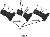
FIG. 1 is a perspective view of a trial femoral neck from left to right in a first image of a contracted neck position, a second image showing a potential neck expansion, and a third image of an expanded neck position. -
FIG. 2 is a perspective view of a trial femoral neck from left to right in a first image of a standard position of the stem in relation to the neck, a second image showing the potential lateral offset of the stem, and a third image of a laterally shifted stem in relation to the neck. -
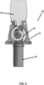
FIG. 3 is a front view of a first embodiment of a neck expansion and contraction mechanism trial femoral neck with a cutaway view within a housing that includes a tilted spiral cam. -
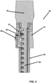
FIG. 4 is a side view of a first embodiment of a neck expansion and contraction mechanism trial femoral neck with a cutaway view of a notched rod interacting with the tilted spiral cam shown inFIG. 3 . -
FIG. 5 is a side view of a first embodiment of a neck expansion and contraction mechanism trial femoral neck rotated ninety degrees fromFIG. 4 with a cutaway view of a notched rod interacting with the tilted spiral cam with the notched rod extended and attached to the head and the bottom of the notched rod secured in a circular lower neck enclosure. -
FIG. 6 is a perspective view of a second embodiment for a neck expansion and contraction mechanism trial femoral neck that includes a driver tool that rotates a bevel pinion gear that engages a bevel gear on a head that expands or contracts the length of the neck. -
FIG. 7 is a perspective cutaway view of a second embodiment for a neck expansion and contraction mechanism trial femoral neck that includes a driver tool that rotates a bevel pinion gear that engages a bevel gear on a head that expands or contracts a length of a neck by engaging a screw located within a coupling sleeve that is secured within a head. -
FIG. 8 is a cutaway perspective view of a third embodiment for a neck expansion and contraction mechanism trial femoral neck that includes a first nested, telescoping threaded element attached to the stem, a third nested, telescoping threaded element attached to the head, and a second nested, telescoping threaded element located between the first nested, telescoping threaded element and the third nested, telescoping threaded element with a threaded nut that can travel up and down the second nested, telescoping threaded element and an anti-rotation guide located between the second nested, telescoping threaded element and the third nested, telescoping threaded element to lock rotation of the second nested, telescoping threaded element and the third nested, telescoping threaded element in relationship to each other in a contracted position. -
FIG. 9 is a cutaway perspective view of a third embodiment for a neck expansion and contraction mechanism trial femoral neck shown inFIG. 8 that includes a first nested, telescoping threaded element attached to the stem; a third nested, telescoping threaded element attached to the head, and a second nested, telescoping threaded element located between the first nested, telescoping threaded element and the third nested, telescoping threaded element with a threaded nut that can travel up and down the second nested, telescoping threaded element and an anti-rotation guide located between the second nested, telescoping threaded element and the third nested, telescoping threaded element to lock rotation of the second nested, telescoping threaded element and the third nested, telescoping threaded element in relationship to each other in an expanded position. -
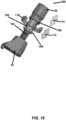
FIG. 10 is a perspective view of a third embodiment for a neck expansion and contraction mechanism trial femoral neck shown inFIG. 8 that includes a first nested, telescoping threaded element attached to the stem; a third nested, telescoping threaded element attached to the head, and a second nested, telescoping threaded element located between the first nested, telescoping threaded element and the third nested, telescoping threaded element with a threaded nut that can travel up and down the second nested, telescoping threaded element and an anti-rotation guide located between the second nested, telescoping threaded element and the third nested, telescoping threaded element to lock rotation of the second nested, telescoping threaded element and the third nested, telescoping threaded element in relationship to each other in an expanded position. - An artisan of ordinary skill in the art need not view, within isolated figure(s), the near-infinite distinct combinations of features described in the following detailed description to facilitate an understanding of the present disclosure.
- The present disclosure is not to be limited to that described herein. Mechanical, electrical, chemical, procedural, and/or other changes can be made without departing from the spirit and scope of the present disclosure. Unless otherwise indicated, no features shown or described are essential to permit basic operation of the present disclosure.
- Trial femoral neck segments and trial femoral modular heads are utilized to assess proper component position, joint stability, range of motion, and leg length.
- Referring now to
FIG. 1 , a trial femoral head and neck assembly is generally indicated by thenumeral 10. The adjustablefemur neck portion 12 of the trial femoral head andneck assembly 10 can adjust from standard to lateralized, and/or could expand over a range of sizes oftrial trunnion 20. Moreover, the adjustablefemur neck portion 12 can expand over a range of sizes that allows the surgeon to adjust theneck portion 12 while just using one neutral (+0 millimeters) trial head and would allow the surgeon to easily change the offset while the patient's joint is still reduced. The expansion mechanism of the adjustablefemoral neck portion 12 will be on the internal portion of the adjustablefemoral neck portion 12. It will be controlled by a separate instrument that the surgeon could turn with a click, indicating that it has adjusted to a new size.Trial trunnion 20 sizes range from -5 millimeters to+ 12 millimeters, so ideally, the trialfemoral neck 20 will be able to expand throughout that entire range. There is astem 22 for attachment to the femur. There can be a broach representative of the final stem implant geometry substituted for thestem 22. The is afirst length 14 of the adjustablefemur neck portion 12, a visual depiction of the expansive of neck portion along theneck axis 16 of the adjustablefemur neck portion 12, and asecond length 18 of the adjustablefemur neck portion 12. The images inFIG. 1 show how the adjustablefemoral neck portion 12 will expand along the axis of the neck to lengthen. It will expand in increments so that the user can easily tell how much they are expanding. Preferably, but not necessarily, it will also be laser marked to show the exact dimension. - Referring now to
FIG. 2 , another feature is to make the trial femoral head andneck 10 adjustable so that a change from standard to lateralized can be accomplished. Currently, there needs to be six total trial necks due to there being three different neck lengths, and one standard and one lateralized option for each one. If the adjustablefemoral neck portion 12 can be adjusted to be lateralized, that would reduce the total number of trial necks from six to three SKUs. As shown, stem 22 can go from a standard position of thestem 24 in relation to the adjustablefemoral neck portion 12, as shown by a lateral change ofstem 26 in relation to the adjustablefemoral neck portion 20 to a lateralized position of thestem 22 to the adjustablefemoral neck portion 28. Thetrunnion 20 can be moved back and forth and could click into the correct place so that the user obtains tactile feedback to verify that the adjustablefemoral neck portion 12 is located in the proper position. Preferably, there would be an indication showing the level of offset. - There is a first embodiment of a neck lengthening device that is generally indicated by the numeral 50 in
FIGS. 3 ,4 , and5 . Positioned below thetrunnion 20 is notchedrod 60 with surfaces that connect to surfaces of a tiltedspiral cam 52. The tiltedspiral cam 52 is located withinhousing 54. Thisneck lengthening device 50 provides an extension of theneck portion 66, shown inFIG. 5 , that cannot be back driven by pressure from the tissue or rotation of thetrunnion 20. The amount ofextension 66 of thetrunnion 20 can be accurately controlled or precisely "dialed in" based on the dimensions of the tiltedspiral cam 52. The tiltedspiral cam 52 includes aprotrusion 58 that engages anopening 59 in thehousing 54 to provide a securing mechanism. The longitudinal neck movement is generally indicated by the numeral 62, and the circular spiral cam movement that is converted to longitudinal neck movement is indicated by the numeral 64.Housing 54 is positioned above theneck portion 56, which is cylindrical and encloses the notchedrod 60. - A second embodiment of a neck lengthening device is generally indicated by the numeral 70 in
FIGS. 6 and7 . There is adriver tool 72 that provides a rotational force. Numerous embodiments of various types of tools can provide this type of rotational force comparable to a hand drill. Thedriver tool 72 includes an enclosedrotating shaft 74 that is attached to abevel pinion gear 78. The direction of rotation of therotating shaft 74 is indicated by the numeral 75. Thebevel pinion gear 78 engages abevel gear 80 that is attached to thetrunnion 20 with the rotation indicated by the numeral 86. As before, theneck portion 56 is positioned on top of thestem 22. - As shown in
FIG. 7 , there is acoupling sleeve 82 that includes abushing 88 that retains acircular protrusion 89 associated with thebevel pinion gear 78. There is retainedflange 94 as an upper component of thecoupling sleeve 82 that is held by aslot 96 in thetrunnion 20. Thebevel gear 80 engages ascrew 92, rotatable in a threadedinternal passage 90, that provides the power to extend and retract thetrunnion 20. Thebevel gear 80 is also connected to thecoupling sleeve 82, which serves to provide a proper alignment of thebevel pinion gear 78 andbevel gear 80 for engagement, as well as provide a bearing surface to guide the extension and retraction ofneck portion 56 indicated bynumeral 62. Thecoupling sleeve 82 is connected to theneck portion 56 by connectingscrews 84, as shown inFIG. 6 . - A third embodiment of a neck lengthening device is generally indicated by the numeral 100 in
FIGS. 8 ,9 , and10 . Thisneck lengthening device 100 includes nested, telescoping, threaded elements, e.g., three, with oppositely handed threads. In an illustrative, but nonlimiting, embodiment, a first nested, telescoping threadedelement 102, e.g., right-hand screw, has a thread running in one direction, e.g., clockwise, with anut 108 with matching internal thread that can go up and down the first nested, telescoping threadedelement 102. - This
nut 108 has an external thread of opposite handedness, e.g., counterclockwise, which engages a third nested, telescoping threadedelement 106, preferably with a matching internal thread, e.g., counterclockwise. This third nested, telescoping threadedelement 106 is connected to the first nested, telescoping threadedelement 102 via ananti-rotation guide 116, which locks the rotation of the first nested, telescoping threadedelement 102 and third nested, telescoping threadedelement 106. When the second nested, telescoping, threadedelement 104 is rotated, it rides up the first nested, telescoping threadedelement 102 and forces the third nested, telescoping threadedelement 106 to extend in the same direction. Because all threadedelements numeral 110 of the threadedelements - Also, because the third nested, telescoping threaded
element 106 is not rotating relative to the first nested, telescoping threadedelement 102 that forms a base element, the rotation of thetrunnion trial 20 does not affect the overall length of theneck lengthening device 100. The longitudinal extension and contraction of the second nested, telescoping, threadedelement 104 is indicated bynumeral 112, and the longitudinal extension and contraction of the third nested, telescoping, threadedelement 106 is indicated bynumeral 114. - The advantage of this trial femoral head and
neck assembly 10 is an expandable trial neck is that it will reduce operating room time by allowing the surgeon to determine the appropriate trial implants (either head offset or stem offset) without dislocating the joint. The surgeon will be able to use an instrument that could provide tactile feedback by clicking at each offset size so that instead of dislocating the joint, replacing the head, and reducing the joint again, the surgeon will be able to leave the joint reduced and turn the instrument to change the offset size.... - This technology will also reduce instrumentation significantly because there could be one trial neck for both standard and lateralized necks. There will also only need to be one neutral offset (+0 millimeter) head that the surgeon will trial with. Reducing instrumentation is especially important in joint arthroplasty due to the increasing presence of ambulatory surgery centers that do not have room to store large amounts of instrumentation. Having less instrumentation also makes things much easier for the scrub technician, making the whole procedure much smoother and quicker.
- From the foregoing, it can be seen that the present disclosure accomplishes at least all of the stated objectives.
- The following table of reference characters and descriptors are not exhaustive, nor limiting, and include reasonable equivalents. If possible, elements identified by a reference character below and/or those elements which are near ubiquitous within the art can replace or supplement any element identified by another reference character.
Table 1: List of Reference Characters 10 Trial femoral head and neck assembly 12 Adjustable femoral neck portion 14 First length of an adjustable femoral neck portion 16 Expansion of neck portion along neck axis 18 Second length of an adjustable femoral neck portion 20 Trunnion 22 Stem or broach 24 Standard position of the stem or broach in relation to an adjustable femoral neck portion 26 Lateral change of stem or broach in relation to an adjustable femoral neck portion 28 Lateralized position of the stem or broach to an adjustable femoral neck portion 50 First embodiment of a neck-lengthening device 52 Tilted spiral cam 54 Housing 56 Neck portion 58 Protrusion 59 Opening 60 Notched rod 62 Longitudinal neck movement 64 Spiral cam movement that converts to longitudinal neck movement 66 Extension of the neck portion 70 Second embodiment of a neck-lengthening device 72 Driver tool 74 Enclosed rotating shaft 75 Direction of rotation of a rotating shaft 78 Bevel pinion gear 80 Bevel gear 82 Coupling sleeve 84 Connecting screws 86 Direction of rotation of the femoral head 88 Bevel pinion gear bushing 89 Circular protrusion 90 Threaded internal passage 92 Screw 94 Retained flange as an upper component of the coupling sleeve 96 Slot located within the trunnion for retaining the retained flange 100 Third embodiment of a neck-lengthening device 102 First nested, telescoping threaded element 104 Second nested, telescoping threaded element 106 Third outer nested, telescoping threaded element 108 Nut 110 Rotation of threaded elements 112 Direction upward and downward of the second nested, telescoping threaded element 114 Direction upward and downward of the third nested, telescoping threaded element 116 Anti-rotation guide - Unless defined otherwise, all technical and scientific terms used above have the same meaning as commonly understood by one of ordinary skill in the art to which embodiments of the present disclosure pertain.
- The terms "a," "an," and "the" include both singular and plural referents.
- The term "or" is synonymous with "and/or" and means any one member or combination of members of a particular list.
- As used herein, the term "exemplary" refers to an example, an instance, or an illustration, and does not indicate a most preferred embodiment unless otherwise stated.
- The term "about" as used herein refers to slight variations in numerical quantities with respect to any quantifiable variable. Inadvertent error can occur, for example, through use of typical measuring techniques or equipment or from differences in the manufacture, source, or purity of components.
- The term "substantially" refers to a great or significant extent. "Substantially" can thus refer to a plurality, majority, and/or a supermajority of said quantifiable variables, given proper context.
- The term "generally" encompasses both "about" and "substantially."
- The term "configured" describes structure capable of performing a task or adopting a particular configuration. The term "configured" can be used interchangeably with other similar phrases, such as constructed, arranged, adapted, manufactured, and the like.
- Terms characterizing sequential order, a position, and/or an orientation are not limiting and are only referenced according to the views presented.
- The "invention" is not intended to refer to any single embodiment of the particular invention but encompass all possible embodiments as described in the specification and the claims. The "scope" of the present disclosure is defined by the appended claims, along with the full scope of equivalents to which such claims are entitled. The scope of the disclosure is further qualified as including any possible modification to any of the aspects and/or embodiments disclosed herein which would result in other embodiments, combinations, subcombinations, or the like that would be obvious to those skilled in the art.
- The invention could be inter alia defined by the following examples:
- 1. A trial femoral assembly for hip arthroplasty, comprising: a head; a neck connected to the head; and a stem or broach connected to the neck, wherein the neck is expandible and collapsible.
- 2. The trial femoral assembly for hip arthroplasty according to Claim 1, wherein the stem or broach can move laterally in relation to the longitudinal axis of the neck.
- 3. The trial femoral assembly for hip arthroplasty according to Example 1, further comprising a notched rod located within a housing and within a circular lower neck portion having a tilted spiral cam that interacts with the notched rod to provide movement involving extension or retraction of the neck.
- 4. The trial femoral assembly for hip arthroplasty according to Example 3, wherein the tilted spiral cam includes a protrusion that engages an opening in the housing to provide a securing mechanism.
- 5. The trial femoral assembly for hip arthroplasty according to Example 1, further comprising a bevel gear located on an outer surface of the head that engages a screw located inside the head to move the neck to provide extension or retraction.
- 6. The trial femoral assembly for hip arthroplasty according to Example 5, further comprising a driver tool attached to a bevel pinion gear that rotates the bevel gear when the bevel pinion gear is in contact with the bevel gear.
- 7. The trial femoral assembly for hip arthroplasty according to Example 5, further comprising a coupling sleeve having a flange member at an outer end that engages a slot located internally within the head.
- 8. The trial femoral assembly for hip arthroplasty according to Example 7, wherein the coupling sleeve is attached to the neck.
- 9. The trial femoral assembly for hip arthroplasty according to Example 1, further comprising a plurality of nested, telescoping threaded elements with oppositely handed threads that extend or retract the neck.
- 10. The trial femoral assembly for hip arthroplasty according to Example 9, further comprising a first nested, telescoping threaded element attached to the stem or broach, a third nested, telescoping threaded element attached to the head, and a second nested, telescoping threaded element located between the first nested, telescoping threaded element attached to the stem or broach and the third nested, telescoping threaded element attached to the head.
- 11. The trial femoral assembly for hip arthroplasty according to Example 10, further comprising a threaded nut that can travel up and down the first nested, telescoping threaded element and an anti-rotation guide located between the first nested, telescoping threaded element and the third nested, telescoping threaded element to lock rotation of the first nested, telescoping threaded element and the third nested, telescoping threaded element in relationship to each other.
- 12. The trial femoral assembly for hip arthroplasty according to Example 11, wherein there is at least a fifty percent overlap between the plurality of nested, telescoping threaded elements at any one time and the threaded nut has threads in the same direction as the third nested, telescoping threaded element and of an opposite direction to that of the first nested, telescoping threaded element, wherein the third nested, telescoping threaded element is not rotating relative to the first nested, telescoping threaded element so that rotation of the head does not affect an overall length of the trial femoral assembly.
- 13. A method of utilizing a trial femoral assembly for hip arthroplasty, comprising: placing a trial femoral assembly on a patient that includes a head, a neck connected to the head, and a stem or broach connected to the neck, where the surgeon can expand or contract the neck to reduce the patient's joint and find the preferred range of motion, soft tissue balance and leg length for the patient.
- 14. The method of utilizing a trial femoral assembly for hip arthroplasty according to Example 13, further comprising the step of laterally moving the stem or broach in relation to a longitudinal axis of the neck.
- 15. The method of utilizing a trial femoral assembly for hip arthroplasty according to Example 13, further comprising utilizing a notched rod located within a housing and within a circular lower neck portion having a tilted spiral cam that interacts with the notched rod to provide movement of the neck for extension or retraction.
- 16. The method of utilizing a trial femoral assembly for hip arthroplasty according to Example 13, further comprising utilizing a bevel gear located on the outer surface of the head that engages a screw located inside the head to provide extension or retraction of the neck.
- 17. The method of utilizing a trial femoral assembly for hip arthroplasty according to Example 16, further comprising utilizing a driver tool attached to the bevel pinion gear that rotates the bevel gear when the bevel pinion gear is in contact with the bevel gear.
- 18. The method of utilizing a trial femoral assembly for hip arthroplasty according to Example 13, further comprising utilizing a plurality of nested, telescoping threaded elements with oppositely handed threads to extend or retract the neck.
- 19. The method of utilizing a trial femoral assembly for hip arthroplasty according to Example 13, further comprising utilizing a first nested, telescoping threaded element attached to the stem or broach, a third nested, telescoping threaded element attached to the head, and a second nested, telescoping threaded element located between the first nested, telescoping threaded element and the third nested, telescoping threaded element to extend or retract the neck.
- 20. The method of utilizing a trial femoral assembly for hip arthroplasty according to Example 19, further comprising utilizing a threaded nut that can travel up and down the first nested, telescoping threaded element and an anti-rotation guide located between the first nested, telescoping threaded element and the third nested, telescoping threaded element to lock rotation of the first nested, telescoping threaded element and the third nested, telescoping threaded element in relationship to each other.
Claims (12)
- A trial femoral assembly for hip arthroplasty, comprising:a head;a neck connected to the head; anda stem or broach connected to the neck, wherein the neck is expandible and collapsible.
- The trial femoral assembly for hip arthroplasty according to Claim 1 or 2, wherein the stem or broach can move laterally in relation to the longitudinal axis of the neck.
- The trial femoral assembly for hip arthroplasty according to any one of the preceding claims, further comprising a notched rod located within a housing and within a circular lower neck portion having a tilted spiral cam that interacts with the notched rod to provide movement involving extension or retraction of the neck.
- The trial femoral assembly for hip arthroplasty according to Claim 3, wherein the tilted spiral cam includes a protrusion that engages an opening in the housing to provide a securing mechanism.
- The trial femoral assembly for hip arthroplasty according to any one of the preceding claims, further comprising a bevel gear located on an outer surface of the head that engages a screw located inside the head to move the neck to provide extension or retraction.
- The trial femoral assembly for hip arthroplasty according to Claim 5, further comprising a driver tool attached to a bevel pinion gear that rotates the bevel gear when the bevel pinion gear is in contact with the bevel gear.
- The trial femoral assembly for hip arthroplasty according to Claim 5, further comprising a coupling sleeve having a flange member at an outer end that engages a slot located internally within the head.
- The trial femoral assembly for hip arthroplasty according to Claim 7, wherein the coupling sleeve is attached to the neck.
- The trial femoral assembly for hip arthroplasty according to any one of the preceding claims, further comprising a plurality of nested, telescoping threaded elements with oppositely handed threads that extend or retract the neck.
- The trial femoral assembly for hip arthroplasty according to Claim 9, further comprising a first nested, telescoping threaded element attached to the stem or broach, a third nested, telescoping threaded element attached to the head, and a second nested, telescoping threaded element located between the first nested, telescoping threaded element attached to the stem or broach and the third nested, telescoping threaded element attached to the head.
- The trial femoral assembly for hip arthroplasty according to Claim 10, further comprising a threaded nut that can travel up and down the first nested, telescoping threaded element and an anti-rotation guide located between the first nested, telescoping threaded element and the third nested, telescoping threaded element to lock rotation of the first nested, telescoping threaded element and the third nested, telescoping threaded element in relationship to each other.
- The trial femoral assembly for hip arthroplasty according to Claim 11, wherein there is at least a fifty percent overlap between the plurality of nested, telescoping threaded elements at any one time and the threaded nut has threads in the same direction as the third nested, telescoping threaded element and of an opposite direction to that of the first nested, telescoping threaded element, wherein the third nested, telescoping threaded element is not rotating relative to the first nested, telescoping threaded element so that rotation of the head does not affect an overall length of the trial femoral assembly.
Applications Claiming Priority (1)
| Application Number | Priority Date | Filing Date | Title |
|---|---|---|---|
| US18/454,472 US20250064592A1 (en) | 2023-08-23 | 2023-08-23 | Expandable trial femoral neck and associated method of use |
Publications (1)
| Publication Number | Publication Date |
|---|---|
| EP4512374A1 true EP4512374A1 (en) | 2025-02-26 |
Family
ID=92503665
Family Applications (1)
| Application Number | Title | Priority Date | Filing Date |
|---|---|---|---|
| EP24195675.4A Pending EP4512374A1 (en) | 2023-08-23 | 2024-08-21 | Expandable trial femoral neck |
Country Status (3)
| Country | Link |
|---|---|
| US (2) | US20250064592A1 (en) |
| EP (1) | EP4512374A1 (en) |
| JP (1) | JP7756211B2 (en) |
Families Citing this family (2)
| Publication number | Priority date | Publication date | Assignee | Title |
|---|---|---|---|---|
| USD1136195S1 (en) * | 2022-04-21 | 2026-07-21 | Depuy Ireland Unlimited Company | Neck trial |
| USD1141127S1 (en) | 2022-04-21 | 2026-08-11 | Depuy Ireland Unlimited Company | Trial liner |
Citations (5)
| Publication number | Priority date | Publication date | Assignee | Title |
|---|---|---|---|---|
| US7425214B1 (en) * | 2005-03-03 | 2008-09-16 | Howmedica Osteonics Corp. | Hip arthroplasty trialing apparatus with adjustable proximal trial and method |
| US20160262912A1 (en) * | 2015-03-13 | 2016-09-15 | Brian G. Burnikel | Temporary, modular, hip joint with neck-length modification mechanism |
| WO2019034769A1 (en) * | 2017-08-18 | 2019-02-21 | Depuy Ireland Unlimited Company | Adjustable trial neck |
| WO2019057698A1 (en) * | 2017-09-19 | 2019-03-28 | Depuy Ireland Unlimited Company | Adjustable trial neck |
| US20210093332A1 (en) * | 2017-12-21 | 2021-04-01 | PMSW Research Pty Ltd | Minimally invasive hip arthroplasty techniques and apparatus |
Family Cites Families (2)
| Publication number | Priority date | Publication date | Assignee | Title |
|---|---|---|---|---|
| US8579985B2 (en) * | 2006-12-07 | 2013-11-12 | Ihip Surgical, Llc | Method and apparatus for hip replacement |
| US20090112210A1 (en) * | 2007-10-30 | 2009-04-30 | Hipco, Inc. | Femoral Neck Support Structure, System, and Method of Use |
-
2023
- 2023-08-23 US US18/454,472 patent/US20250064592A1/en active Pending
-
2024
- 2024-08-21 EP EP24195675.4A patent/EP4512374A1/en active Pending
- 2024-08-23 JP JP2024141909A patent/JP7756211B2/en active Active
-
2026
- 2026-03-23 US US19/574,534 patent/US20260215925A1/en active Pending
Patent Citations (5)
| Publication number | Priority date | Publication date | Assignee | Title |
|---|---|---|---|---|
| US7425214B1 (en) * | 2005-03-03 | 2008-09-16 | Howmedica Osteonics Corp. | Hip arthroplasty trialing apparatus with adjustable proximal trial and method |
| US20160262912A1 (en) * | 2015-03-13 | 2016-09-15 | Brian G. Burnikel | Temporary, modular, hip joint with neck-length modification mechanism |
| WO2019034769A1 (en) * | 2017-08-18 | 2019-02-21 | Depuy Ireland Unlimited Company | Adjustable trial neck |
| WO2019057698A1 (en) * | 2017-09-19 | 2019-03-28 | Depuy Ireland Unlimited Company | Adjustable trial neck |
| US20210093332A1 (en) * | 2017-12-21 | 2021-04-01 | PMSW Research Pty Ltd | Minimally invasive hip arthroplasty techniques and apparatus |
Also Published As
| Publication number | Publication date |
|---|---|
| JP7756211B2 (en) | 2025-10-17 |
| US20260215925A1 (en) | 2026-07-30 |
| JP2025031685A (en) | 2025-03-07 |
| US20250064592A1 (en) | 2025-02-27 |
Similar Documents
| Publication | Publication Date | Title |
|---|---|---|
| US20250064592A1 (en) | Expandable trial femoral neck and associated method of use | |
| US20250064603A1 (en) | Expandable trial femoral neck and associated method of use | |
| US8518050B2 (en) | Modular taper assembly device | |
| US20250152275A1 (en) | Depth limiter for robotically assisted arthroplasty | |
| US8632546B2 (en) | Expandable proximal reamer | |
| US12232774B2 (en) | Adjustable strut assemblies for external fixation systems | |
| US6918914B2 (en) | Minimally invasive adjustable acetubular reamer | |
| US7297166B2 (en) | Assembly tool for modular implants and associated method | |
| US8998919B2 (en) | Assembly tool for modular implants, kit and associated method | |
| US20160262912A1 (en) | Temporary, modular, hip joint with neck-length modification mechanism | |
| US20130289567A1 (en) | Proximal reamer | |
| RU2663714C2 (en) | Implant trialling | |
| US20220339005A1 (en) | Joint replacement alignment guides, systems and methods of use and assembly | |
| EP3618732B1 (en) | Targeting system for the guided insertion of a guide wire or a bone screw | |
| US8956357B2 (en) | Expandable proximal reamer | |
| WO2019034769A1 (en) | Adjustable trial neck | |
| AU2006251341A2 (en) | Femoral neck prosthesis | |
| CN111956330B (en) | Quick locking detachable surgical mechanical device | |
| IT202000016882A1 (en) | DEVICE FOR FINISHING AND CUTTING A BONE GRAFT | |
| CN213787730U (en) | High-precision multi-dimensional adjustment device | |
| US20250325285A1 (en) | Reaming Guide System and Method for Using Same | |
| CN112244975A (en) | High-precision multi-dimensional adjustment device |
Legal Events
| Date | Code | Title | Description |
|---|---|---|---|
| PUAI | Public reference made under article 153(3) epc to a published international application that has entered the european phase |
Free format text: ORIGINAL CODE: 0009012 |
|
| STAA | Information on the status of an ep patent application or granted ep patent |
Free format text: STATUS: REQUEST FOR EXAMINATION WAS MADE |
|
| 17P | Request for examination filed |
Effective date: 20240821 |
|
| AK | Designated contracting states |
Kind code of ref document: A1 Designated state(s): AL AT BE BG CH CY CZ DE DK EE ES FI FR GB GR HR HU IE IS IT LI LT LU LV MC ME MK MT NL NO PL PT RO RS SE SI SK SM TR |
|
| STAA | Information on the status of an ep patent application or granted ep patent |
Free format text: STATUS: EXAMINATION IS IN PROGRESS |
|
| 17Q | First examination report despatched |
Effective date: 20260522 |