EP4512360A1 - Camera-based guidance for needle intervention - Google Patents
Camera-based guidance for needle intervention Download PDFInfo
- Publication number
- EP4512360A1 EP4512360A1 EP24153415.5A EP24153415A EP4512360A1 EP 4512360 A1 EP4512360 A1 EP 4512360A1 EP 24153415 A EP24153415 A EP 24153415A EP 4512360 A1 EP4512360 A1 EP 4512360A1
- Authority
- EP
- European Patent Office
- Prior art keywords
- needle
- image data
- cam
- camera
- sub
- Prior art date
- Legal status (The legal status is an assumption and is not a legal conclusion. Google has not performed a legal analysis and makes no representation as to the accuracy of the status listed.)
- Pending
Links
Images



Classifications
-
- A—HUMAN NECESSITIES
- A61—MEDICAL OR VETERINARY SCIENCE; HYGIENE
- A61B—DIAGNOSIS; SURGERY; IDENTIFICATION
- A61B90/00—Instruments, implements or accessories specially adapted for surgery or diagnosis and not covered by any of the groups A61B1/00 - A61B50/00, e.g. for luxation treatment or for protecting wound edges
- A61B90/36—Image-producing devices or illumination devices not otherwise provided for
-
- A—HUMAN NECESSITIES
- A61—MEDICAL OR VETERINARY SCIENCE; HYGIENE
- A61B—DIAGNOSIS; SURGERY; IDENTIFICATION
- A61B90/00—Instruments, implements or accessories specially adapted for surgery or diagnosis and not covered by any of the groups A61B1/00 - A61B50/00, e.g. for luxation treatment or for protecting wound edges
- A61B90/36—Image-producing devices or illumination devices not otherwise provided for
- A61B90/361—Image-producing devices, e.g. surgical cameras
-
- A—HUMAN NECESSITIES
- A61—MEDICAL OR VETERINARY SCIENCE; HYGIENE
- A61B—DIAGNOSIS; SURGERY; IDENTIFICATION
- A61B34/00—Computer-aided surgery; Manipulators or robots specially adapted for use in surgery
- A61B34/10—Computer-aided planning, simulation or modelling of surgical operations
-
- A—HUMAN NECESSITIES
- A61—MEDICAL OR VETERINARY SCIENCE; HYGIENE
- A61B—DIAGNOSIS; SURGERY; IDENTIFICATION
- A61B90/00—Instruments, implements or accessories specially adapted for surgery or diagnosis and not covered by any of the groups A61B1/00 - A61B50/00, e.g. for luxation treatment or for protecting wound edges
- A61B90/10—Instruments, implements or accessories specially adapted for surgery or diagnosis and not covered by any of the groups A61B1/00 - A61B50/00, e.g. for luxation treatment or for protecting wound edges for stereotaxic surgery, e.g. frame-based stereotaxis
- A61B90/11—Instruments, implements or accessories specially adapted for surgery or diagnosis and not covered by any of the groups A61B1/00 - A61B50/00, e.g. for luxation treatment or for protecting wound edges for stereotaxic surgery, e.g. frame-based stereotaxis with guides for needles or instruments, e.g. arcuate slides or ball joints
- A61B90/13—Instruments, implements or accessories specially adapted for surgery or diagnosis and not covered by any of the groups A61B1/00 - A61B50/00, e.g. for luxation treatment or for protecting wound edges for stereotaxic surgery, e.g. frame-based stereotaxis with guides for needles or instruments, e.g. arcuate slides or ball joints guided by light, e.g. laser pointers
-
- A—HUMAN NECESSITIES
- A61—MEDICAL OR VETERINARY SCIENCE; HYGIENE
- A61B—DIAGNOSIS; SURGERY; IDENTIFICATION
- A61B34/00—Computer-aided surgery; Manipulators or robots specially adapted for use in surgery
- A61B34/10—Computer-aided planning, simulation or modelling of surgical operations
- A61B2034/107—Visualisation of planned trajectories or target regions
-
- A—HUMAN NECESSITIES
- A61—MEDICAL OR VETERINARY SCIENCE; HYGIENE
- A61B—DIAGNOSIS; SURGERY; IDENTIFICATION
- A61B90/00—Instruments, implements or accessories specially adapted for surgery or diagnosis and not covered by any of the groups A61B1/00 - A61B50/00, e.g. for luxation treatment or for protecting wound edges
- A61B90/36—Image-producing devices or illumination devices not otherwise provided for
- A61B2090/364—Correlation of different images or relation of image positions in respect to the body
- A61B2090/365—Correlation of different images or relation of image positions in respect to the body augmented reality, i.e. correlating a live optical image with another image
-
- A—HUMAN NECESSITIES
- A61—MEDICAL OR VETERINARY SCIENCE; HYGIENE
- A61B—DIAGNOSIS; SURGERY; IDENTIFICATION
- A61B90/00—Instruments, implements or accessories specially adapted for surgery or diagnosis and not covered by any of the groups A61B1/00 - A61B50/00, e.g. for luxation treatment or for protecting wound edges
- A61B90/36—Image-producing devices or illumination devices not otherwise provided for
- A61B90/37—Surgical systems with images on a monitor during operation
- A61B2090/372—Details of monitor hardware
-
- A—HUMAN NECESSITIES
- A61—MEDICAL OR VETERINARY SCIENCE; HYGIENE
- A61B—DIAGNOSIS; SURGERY; IDENTIFICATION
- A61B90/00—Instruments, implements or accessories specially adapted for surgery or diagnosis and not covered by any of the groups A61B1/00 - A61B50/00, e.g. for luxation treatment or for protecting wound edges
- A61B90/36—Image-producing devices or illumination devices not otherwise provided for
- A61B90/37—Surgical systems with images on a monitor during operation
- A61B2090/376—Surgical systems with images on a monitor during operation using X-rays, e.g. fluoroscopy
- A61B2090/3762—Surgical systems with images on a monitor during operation using X-rays, e.g. fluoroscopy using computed tomography systems [CT]
Definitions
- the invention relates to a method for generating augmented camera image data for guiding a needle intervention.
- the invention also concerns a camera-based method for guiding a needle intervention. Further, the invention refers to an intervention control device. Furthermore, the invention relates to an intervention system.
- a needle path is planned based on a planning scan, e.g. a CT spiral scan.
- the planning consists of annotating a target point inside the body where the needle tip shall be positioned, and a needle insertion point on the skin surface.
- the needle path is planned such that sensitive structures like vessels, other organs, or bones are not harmed.
- the key challenge in intervention workflows is to transfer the needle path planned based on the medical data to the actual patient. In particular, the exact insertion point on the skin has to be located and the correct direction has to be applied when inserting the needle into the body.
- the z-position of the slice (the z-axis is the symmetry axis of the medical imaging system) in which the entry point is located is read from the image text of the planning scan.
- the patient table is positioned in a way that this z-position exactly lines up with the scan plane, which is marked by the gantry laser. In this way, the z-position for the injection point is located.
- the distance on the skin from the central laser is measured within the planning image and is also measured on the actual patient with a ruler and marked on the skin.
- a metal grid can be used which is taped to the skin before the planning scan and which has metal wires running parallel in z-direction.
- the wires appear on the planning scan and can be used to identify the ideal injection point (e.g. between the 3 rd and 4 th wire from the left).
- the needle When the injection point has been located and marked on the patient's skin using one of the two methods described above, the needle must be inserted into the skin with the correct angle as planned in the planning scan.
- the user views the planned needle path on an in-room monitor next to the patient and aligns the angle in which he injects the needle into patient's body with the angle of the planned needle path using an eye balling approach. If the needle path is only tilted within the x-y scan plane (in-plane intervention) this method works relatively well.
- This task is accomplished by a method for generating augmented camera image data for guiding a needle intervention according to claim 1, by a camera-based method for guiding a needle intervention according to claim 11, by an intervention control device according to claim 12 and by an intervention system according to claim 13.
- the method for generating augmented camera image data for guiding a needle intervention comprises the step of receiving medical image data of an examination portion of a patient.
- the examination portion comprises a region of the body of a patient which is intended to be the object of a medical intervention performed using a needle.
- the medical image data are generated by a medical imaging system.
- the medical imaging system comprises an imaging technique for generating 3D medical images of the inside of the body of a patient.
- the medical imaging system preferably comprises an X-ray based imaging system.
- the medical imaging system comprises a computer tomography system.
- the medical imaging may alternatively comprise other modalities, e.g. a magnetic resonance or ultrasound imaging system.
- the medical image data preferably comprise 3D images.
- the medical image data provide information for determining and planning a pose of a needle for a planned intervention.
- the medical image data comprise information about the interior of the body of a patient and details of the examination portion such that sub-portions of the inner body which have to be avoided by the needle and sub-portions of the inner body which are intended to be drilled through by the needle are able to be identified and to be localized.
- the medical image data are assigned to a coordinate system of the medical image data.
- Such a medical image data coordinate system preferably comprises a 3D-coordinate system including the origin on a symmetry axis, in particular the z-axis of the medical imaging system.
- camera image data of the examination portion are received.
- the camera image data are generated by an observation camera or monitoring camera being arranged in the examination room for observing the patient lying on the patient table of the medical imaging system.
- the camera comprises a 2D image camera. 2D images enable a complete overview of an insertion scenario.
- the camera image data are intended to be used for monitoring and guiding a needle intervention in an examination portion of a patient.
- the coordinate system of the camera also named camera coordinate system, differs from the coordinate system of the medical imaging system.
- information concerning a planned insertion pose of the needle is determined based on the received medical image data as already mentioned above.
- the information about the planned insertion pose of the needle comprises at least information about a planned position of the needle, in particular of a planned insertion position of the needle and an orientation of the needle while the needle is inserted.
- the information concerning a planned insertion pose of the needle preferably comprises information about the planned end position of the tip of the needle and also preferred information about the planned end position of the head of the needle and further preferred information about the planned orientation of the needle at the end position.
- coordinates assigned to the planned insertion pose of the needle in the medical image data coordinate system are determined based on the medical image data.
- the medical image data provide information about organs or bones or tissue or blood vessels to be targeted in the body of a patient using the needle and organs or bones or tissue or blood vessels to be avoided by the needle.
- coordinates assigned to the planned insertion pose of the needle in the camera coordinate system of the camera are determined by transforming the coordinates assigned to the planned insertion pose of the needle from the medical image data coordinate system into the camera coordinate system.
- the coordinate system of the medical imaging system and the coordinate system of the camera differ from each other due to different positions of the origins of these different systems, due to different orientation of these systems and possibly due to a different geometry of these systems.
- a planned pose of the needle is able to be determined.
- the template for the needle is to be shown in the display of the camera, a transformation between the coordinate systems of these different systems has to be performed.
- augmented camera image data are generated based on the determined coordinates in the camera coordinate system and the received camera image data by combining templates or marks based on the determined coordinates with the received camera image data.
- the workflow step of transferring a planned needle path to the actual patient can be simplified significantly.
- Many modern medical imaging systems are already equipped with cameras for patient observation or for patient positioning and scan automation.
- observation cameras are also frequently installed in examination rooms.
- the use of an already existing camera in the context of an imaging-guided medical intervention workflow, particularly for the initial placement of the needle provides a precise placement of the needle based on a path planned using the medical imaging data.
- the display of the needle tip may help to save time and to avoid mistakes during the otherwise manual transfer of the medical imaging planning result to the skin of the patient.
- having a good indication of the planned needle orientation and stop position may help to avoid some control scans during the intervention to track the needle, thereby saving time and radiation dose.
- there is no need for additional resources as already existing and installed hardware is used for observing the needle.
- the method for generating augmented camera image data for guiding a needle according to the invention is performed, wherein coordinates assigned to a planned insertion pose of the needle in a camera coordinate system of a camera are determined and augmented camera image data are generated based thereon.
- the augmented camera image data preferably comprise templates or marks as needle alignment guide for guiding an insertion of the needle.
- the templates or marks comprise a guideline, preferably comprising at least one of the following signs: a dotted line, a solid line, a marking cross, a marking circle.
- the augmented camera image data are displayed.
- the needle and a planned pose of the needle are displayed in the camera image data based on the determined coordinates.
- the camera-based method for guiding a needle intervention according to the invention shares the advantages of the method for generating augmented camera image data for guiding a needle intervention.
- the intervention control device comprises a medical image data interface for receiving medical image data of an examination portion of a patient and a camera image data interface for receiving camera image data of the examination portion.
- the intervention control device comprises a determination unit for determining information concerning a planned insertion pose of a needle based on the received medical image data. For determining information concerning a planned insertion pose of the needle, coordinates assigned to the insertion pose of the needle in the medical image data coordinate system are determined based on the medical image data.
- the intervention control device comprises a transformation unit for determining the coordinates assigned to the insertion pose of the needle in the camera coordinate system of the camera by transforming the coordinates assigned to the insertion pose in the medical image data coordinate system into the camera coordinate system.
- the intervention control device also comprises a generation unit for generating augmented camera image data based on the determined coordinates in the camera coordinate system and based on the received camera image data.
- the intervention control device shares the advantages of the camera-based guidance method for guiding a needle intervention according to the invention.
- the intervention system comprises a medical imaging system, preferably a CT-system, for generating medical image data from an examination portion of a patient. Further, the intervention system comprises a camera for observing the patient and for acquiring camera image data from the patient and in particular from the examination portion of the patient. Furthermore, the intervention system includes a needle for an intervention.
- a medical imaging system preferably a CT-system
- the intervention system comprises a camera for observing the patient and for acquiring camera image data from the patient and in particular from the examination portion of the patient.
- the intervention system includes a needle for an intervention.
- the intervention system also comprises an intervention control device according to the invention for generating augmented camera image data based on medical image data from the medical imaging system and camera data from the camera and for controlling the intervention using the needle based on the augmented camera image data.
- the intervention system further comprises a display for displaying the augmented camera image data generated by the intervention control device.
- the needle and a template or mark indicating a planned pose of the needle are depicted.
- the display is used for displaying the camera image data and for displaying a template of the planned pose of the needle such that a physician is enabled to follow the displayed template with the needle.
- Some units or modules of the intervention control device mentioned above can be completely or partially realized as software modules running on a processor of a respective computing system, e.g. of a control device of a medical imaging system.
- a realization largely in the form of software modules can have the advantage that applications already installed on an existing computing system can be updated, with relatively little effort, to install and run these units of the present application.
- the object of the invention is also achieved by a computer program product with a computer program that is directly loadable into the memory of a computing system, and which comprises program units to perform the steps of the inventive method for generating augmented camera image data for guiding a needle intervention, in particular the steps of receiving medical image data, of receiving camera image data, of determining information concerning a planned insertion pose of the needle, of determining coordinates assigned to the planned insertion pose of the needle in the camera coordinate system and of generating augmented camera image data, or the software-based steps of the camera-based method for guiding a needle intervention, in particular the above-mentioned steps of the method for generating augmented camera image data for guiding a needle intervention, when the program is executed by the computing system.
- a computer program product can also comprise further parts such as documentation and/or additional components, also hardware components such as a hardware key (dongle etc.) to facilitate access to the software.
- a computer readable medium such as a memory stick, a harddisk or other transportable or permanently-installed carrier can serve to transport and/or to store the executable parts of the computer program product so that these can be read from a processor unit of a computing system.
- a processor unit can comprise one or more microprocessors or their equivalents.
- the information concerning a planned insertion pose of the needle in the received medical image data comprises an insertion point of the needle.
- the planned insertion point is displayed as template such that a physician is enabled to guide the needle to the virtually marked insertion position visible on a display.
- the needle insertion point q CT from the planning scan i.e. the medical image data in the medical image data coordinate system
- the intrinsic calibration of the camera consists of the focal length f, the principal point, and distortion coefficients.
- a visual marker like a dot is displayed as an overlay onto the camera image in the camera image data. The physician can then align the tip of the actual needle with the marker to insert the needle at the right position.
- the sub-step of transforming the coordinates assigned to the insertion pose in the medical image data coordinate system into a 3D camera coordinate system comprises an application of a camera transform T CT,CAM to the insertion pose assigned to the medical image data coordinate system.
- the coordinates are transformed into the coordinate system of the camera which is used for observing the needle and in particular the insertion of the needle.
- the sub-step of transforming the coordinates assigned to the insertion pose in the medical image data coordinate system into a 3D camera coordinate system comprises an application of a transformation T TABLE representing a new table position in case the table position is changed.
- a movement of the table is taken into account for the coordinates in the camera image.
- the camera transform T CT,CAM is determined based on an extrinsic calibration step.
- the camera transform T CT,CAM can be calculated based on extrinsic calibration parameters. Extrinsic parameters describe the position and orientation of a camera in space.
- the camera image data comprise 2D camera image data as discussed later.
- 2D image data can be simply acquired and easily perceived by a physician, wherein the physician gets a complete overview of a needle insertion scenario.
- the information concerning a planned insertion pose of the needle based on the received medical image data comprises a needle orientation for the needle intervention and the step of determining information concerning an insertion pose of the needle in the received medical image data comprises at least one of the following sub-steps, preferably more than one of the following sub-steps, most preferably all of the following sub-steps, of determining:
- the augmented-reality visualization is further enriched with information about the orientation in which the needle shall be inserted.
- the physician receives all the information about the planned pose of the needle to be inserted into the examination portion.
- the knowledge about the length 1 of the needle is used. Then the needle end point u CT in the medical image data coordinate system is constructed at the start of the insertion by virtually moving the needle insertion point q CT in opposite direction of the planned needle direction.
- the needle insertion point q and the end point u are visualized for example as dots or as line ranging from q 2D to u 2D in a live camera image, preferably a 2D live camera image.
- the needle end point u CT at the start of the insertion is determined by virtually moving the needle insertion point q CT in the opposite direction of the planned needle direction, as explained in context with formula (4).
- a second marking point for positioning the needle at the start of the insertion is determined which facilitates the positioning and alignment of the needle at the beginning of the insertion.
- the information concerning an insertion pose of the needle in the received medical image data preferably comprises an end point of the needle head at the end of the needle intervention.
- the physician receives a precise information about the end position of the needle head he has to reach in the end of the insertion.
- the information concerning a planned insertion pose comprises an end point of the needle head at the end of the needle intervention
- the end point of the needle head at the end of the needle intervention is determined by adding the target needle tip position to the end point of the needle at the start of the insertion and subtracting therefrom the insertion point of the needle.
- v CT u CT + p CT ⁇ q CT , wherein the needle tip is transferred to the target needle tip position p CT inside the body.
- a visual indication like a dot is then placed at this position to indicate the stop position for the needle end point in the live 2D camera image.
- the step of determining the coordinates assigned to the insertion pose of the needle in the camera image data preferably includes the sub-steps of:
- the target points of the needle are projected into 2D camera image data, which are used for observing the patient and in particular the examination portion.
- the sub-step of projecting the coordinates concerning the planned insertion pose into the camera image data preferably comprises the step of applying a projection T CT,CAM to the coordinates concerning the insertion pose in the 3D camera coordinate system.
- FIG 1 a schematic illustration 10 of an intervention using a needle 1 guided by a laser beam LB of a laser L according to prior art is shown.
- the initial needle placement on a planned path is assisted by a laser L emitting a laser beam LB onto a patient P, wherein a marking point MP is projected onto the planned insertion position q of the needle 1.
- a physician M places the needle 1 on the marked insertion point q guided by the laser beam LB.
- FIG 2 a schematic illustration 20 of an intervention using a needle 1 guided by a camera of a smartphone 2 is depicted.
- a smartphone application overlays the planned angle on the smartphone's camera display 3 in real-time based on the smartphone's orientation.
- the needle's angle is selected by visually comparing the actual needle with the guideline GL in the display 3 of the smartphone 2.
- this system also lacks integration with the CT system.
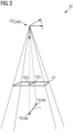
- FIG 3 a perspective view 30 of a perspective projection of points q, u in 3D-space onto an image plane or view plane VP is shown.
- a coordinate system KS CAM of the camera is depicted, wherein the origin of the coordinate system represents the camera origin.
- the view plane VP of the camera a projection of the needle 1 and particularly the projected insertion point q 2D and the projected end point u 2D of the needle 1 are illustrated.
- the needle 1 itself in 3D space is illustrated and the insertion point q CAM and the endpoint u CAM of the needle 1 at the start of the intervention are depicted.
- FIG 4 a sectional view 40 of a perspective projection of points in 3D-space onto the image view plane VP is shown.
- FIG 5 a 2D view of the projected insertion point q 2D and the projected end point u 2D at the start of the intervention in the image plane VP is illustrated.
- the intersection point c of the z axis of the 3D camera coordinate system with the view plane VP of the camera is marked.
- the u-axis u and the v-axis v of the coordinate system of the view plane VP is marked on the lower left portion of FIG 5 .
- FIG 6 a virtual image 60 of a needle 1 at the beginning of a treatment is shown.
- the needle alignment guide NAG i.e. the initial needle orientation, is drawn as a solid line. The user needs to align the real needle tip T with one ending of the virtual guidance needle overlay and the needle head h with the other ending of the virtual needle.
- the visualization q 2D of the needle insertion point q is achieved as follows: in order to provide augmented-reality guidance to the physician M during the intervention, a real-time view of the patient P acquired with the camera is displayed on a screen, for example on an in-room monitor or a tablet next to the patient P. In addition, the planned needle insertion point q is displayed as an overlay graphic, as illustrated in FIG 6 . Therefore, the transformation T CT,AM from scanner / medical image coordinates to camera coordinates is determined in an extrinsic calibration step. This step is performed once during installation of the camera. The calibration can be performed for example with a checkerboard phantom that is aligned to the scanner positioning lasers.
- the insertion point q CT from the planning scan can be transferred to the camera image point q CAM using the scanner to camera transform T CT,CAM as mentioned in formula (1) .
- the needle insertion point in camera coordinates q CAM is then projected into the camera image using the intrinsic calibration expressed through the projection P CAM according to formula (3).
- the intrinsic calibration of the camera consists of the focal length f, the principal point, and distortion coefficients.
- a visual marker like a dot is displayed as an overlay onto the live camera image. The physician can then align the tip of the actual needle with the marker to insert the needle at the right position.
- FIG 7 a virtual image 70 of a needle 1 when the needle 1 is partially inserted, is shown.
- the projected insertion point q 2D is visualized as a cross.
- the augmented-reality visualization may be further enriched with information about the orientation in which the needle 1 shall be inserted. Therefore, the length l of the needle 1 is entered into the system.
- the system then constructs the needle end point u CT at the start of the insertion by moving the needle insertion point q CT in opposite direction of the planned needle direction.
- the direction d CT from the needle insertion point q to the planned needle end point is calculated according to formula (4).
- the needle end point u CT is calculated according to formula (5) .
- This needle end point u CT is then also transformed to camera coordinates u CAM and projected into the 2D camera image according to formula (6).
- the needle insertion point q and end point u are visualized for example as dots or as line ranging from q 2D to u 2D in the live 2D camera image, as illustrated in FIG 6 .
- the physician aligns the tip T of the actual needle 1 in the live 2D camera image with the projected needle insertion point q 2D to set the insertion point and the end of the needle with the projected needle end point u 2D to set the needle direction.
- FIG 8 a virtual image 80 of a needle 1 including the planned needle end position is shown.
- the planned needle end position v is visualized by the projected planned needle end position V 2D to indicate to the user when to stop the insertion as the planned target position p of the tip of the needle (not shown) is reached. Further, also the projected insertion point q 2D is visualized in FIG 8 .
- the initial needle orientation is drawn as a dashed line.
- the visualization may also comprise information about the target point p where the needle shall stop inside the body.
- the tip of the needle obviously cannot be seen as it approaches the target point p inside the body.
- the visualization on the outside of the body can indicate where the end of the needle shall be when the tip is at the target. Therefore, the end point v CT of the needle head (at the start of the intervention) is moved in needle direction according to formula (7).
- the position v 2D of the end point v CT of the needle head at the end of the intervention in 2D camera image data is calculated according to formula (8).
- a visual indication like a dot is then placed at this position to indicate the stop position for the needle end point in the live 2D camera image, as illustrated in FIG 8 .
- FIG 9 a flow chart 900 is shown, illustrating the camera-based method for determining information for guiding a needle intervention.
- step 9.I medical image data MID of an examination portion of a patient P are received.
- step 9.II camera image data CID of the examination portion are received.
- an planned insertion position q CT , a needle end point u CT during the start of insertion of the needle 1 and a planned needle end position v CT are determined in the received medical image data MID in the medical image data coordinate system KS CT .
- the template for the planned insertion of a needle is preferably determined such that the violation of organs is avoided and the examination portion is hit by the needle.
- step 9.IV the coordinates q CT , u CT , v CT assigned to the planned insertion pose of the needle 1 are transformed from the medical image data coordinate system KS CT into a 3D camera coordinate system KS CAM .
- step 9.V the transformed coordinates q CAM , u CAM , v cam are projected into a 2D camera image coordinate system and 2D coordinates p 2D , u 2D , v 2D assigned to the planned insertion pose are determined.
- step 9.VI augmented camera image data ACID are generated based on the determined 2D coordinates p 2D , u 2D , v 2D and the camera image data CID.
- FIG 10 a schematic view of an intervention control device 100 according to an embodiment of the invention is shown.
- the intervention control device 100 comprises a medical image data interface 101 for receiving medical image data MID of an examination portion of a patient.
- the intervention control device 100 comprises a camera image data interface 102 for receiving camera image data CID of the examination portion.
- the intervention control device 100 comprises a determination unit 103 for determining information concerning an insertion pose of the needle 1 in the received medical image data MID, wherein coordinates q CT , u CT , v CT assigned to the insertion pose of the needle 1 in the medical image data coordinate system KS CT are determined.
- the intervention control device 100 also includes a transformation unit 104 for transforming the coordinates q CT , u CT , v CT assigned to the insertion pose of the needle 1 in the medical image data coordinate system KS CT into 2D coordinates q 2D , u 2D , v 2D assigned to a 2D view plane of the camera.
- the intervention control device 100 further comprises a generation unit 105 for generating augmented camera image data ACID based on the determined coordinates q 2D , u 2D , v 2D in the camera coordinate system KS CAM and based on the received camera image data CID.
Landscapes
- Health & Medical Sciences (AREA)
- Surgery (AREA)
- Life Sciences & Earth Sciences (AREA)
- Engineering & Computer Science (AREA)
- Animal Behavior & Ethology (AREA)
- General Health & Medical Sciences (AREA)
- Biomedical Technology (AREA)
- Heart & Thoracic Surgery (AREA)
- Medical Informatics (AREA)
- Molecular Biology (AREA)
- Nuclear Medicine, Radiotherapy & Molecular Imaging (AREA)
- Veterinary Medicine (AREA)
- Public Health (AREA)
- Oral & Maxillofacial Surgery (AREA)
- Pathology (AREA)
- Robotics (AREA)
- Physics & Mathematics (AREA)
- Optics & Photonics (AREA)
- Infusion, Injection, And Reservoir Apparatuses (AREA)
- Apparatus For Radiation Diagnosis (AREA)
Abstract
A method for generating augmented camera image data (ACID) for guiding a needle intervention is described. According to the method for determining information for guiding a needle intervention, medical image data (MID) of an examination portion of a patient are received and also camera image data (CID) of the examination portion are received. Further, information concerning a planned insertion pose of the needle (1) are determined based on the received medical image data (MID), wherein coordinates (q<sub>CT</sub>, u<sub>CT</sub>, v<sub>CT</sub>) assigned to the planned insertion pose of the needle (1) in a coordinate system (KS<sub>CT</sub>) of the medical image data are (MID) determined. Furthermore, coordinates (q<sub>2D</sub>, u<sub>2D</sub>, v<sub>2D</sub>, q<sub>CAM</sub>, u<sub>CAM</sub>, v<sub>CAM</sub>) assigned to the planned insertion pose of the needle (1) in the camera coordinate system (KS<sub>CAM</sub>) of the camera (CAM) are determined by transforming the coordinates (q<sub>CT</sub>, u<sub>CT</sub>, v<sub>CT</sub>) assigned to the planned insertion pose from the medical image data coordinate system (KS<sub>CT</sub>) into the camera coordinate system (KS<sub>CAM</sub>). In the end, augmented camera image data (ACID) are generated based on the determined coordinates (q<sub>2D</sub>, u<sub>2D</sub>, v<sub>2D</sub>, q<sub>CAM</sub>, u<sub>CAM</sub>, v<sub>CAM</sub>) in the camera coordinate system (KS<sub>CAM</sub>) and the received camera image data (CID). Further, a camera-based method for guiding a needle intervention is described. Also an intervention control device (100) is described. Furthermore, an intervention system (110) is described.
Description
- The invention relates to a method for generating augmented camera image data for guiding a needle intervention. The invention also concerns a camera-based method for guiding a needle intervention. Further, the invention refers to an intervention control device. Furthermore, the invention relates to an intervention system.
- Medical imaging systems are also often used to guide needle interventions like biopsies. During preparation of the intervention, a needle path is planned based on a planning scan, e.g. a CT spiral scan. The planning consists of annotating a target point inside the body where the needle tip shall be positioned, and a needle insertion point on the skin surface. The needle path is planned such that sensitive structures like vessels, other organs, or bones are not harmed. The key challenge in intervention workflows is to transfer the needle path planned based on the medical data to the actual patient. In particular, the exact insertion point on the skin has to be located and the correct direction has to be applied when inserting the needle into the body.
- For identification of the needle entry point on the patient's skin, the following workflow is most common: the z-position of the slice (the z-axis is the symmetry axis of the medical imaging system) in which the entry point is located is read from the image text of the planning scan. The patient table is positioned in a way that this z-position exactly lines up with the scan plane, which is marked by the gantry laser. In this way, the z-position for the injection point is located. To identify the x- and y-position within the z-plane, the distance on the skin from the central laser is measured within the planning image and is also measured on the actual patient with a ruler and marked on the skin. As an alternative for this measurement, a metal grid can be used which is taped to the skin before the planning scan and which has metal wires running parallel in z-direction.
- The wires appear on the planning scan and can be used to identify the ideal injection point (e.g. between the 3rd and 4th wire from the left). When the injection point has been located and marked on the patient's skin using one of the two methods described above, the needle must be inserted into the skin with the correct angle as planned in the planning scan. The user views the planned needle path on an in-room monitor next to the patient and aligns the angle in which he injects the needle into patient's body with the angle of the planned needle path using an eye balling approach. If the needle path is only tilted within the x-y scan plane (in-plane intervention) this method works relatively well. However, if the needle is also tilted towards the z-axis (double angulated needle path) this is not easy to accomplish by eyeballing resulting in a decreased precision. As an alternative, few radiologists actually measure the angle of the needle to match the angle on the planned needle path.
- It is therefore a task to provide a method and a system for guiding a needle intervention with more reliability than in prior art.
- This task is accomplished by a method for generating augmented camera image data for guiding a needle intervention according to
claim 1, by a camera-based method for guiding a needle intervention according to claim 11, by an intervention control device according to claim 12 and by an intervention system according to claim 13. - The method for generating augmented camera image data for guiding a needle intervention according to the invention comprises the step of receiving medical image data of an examination portion of a patient. The examination portion comprises a region of the body of a patient which is intended to be the object of a medical intervention performed using a needle. The medical image data are generated by a medical imaging system. The medical imaging system comprises an imaging technique for generating 3D medical images of the inside of the body of a patient. The medical imaging system preferably comprises an X-ray based imaging system. Most preferably, the medical imaging system comprises a computer tomography system. However, the medical imaging may alternatively comprise other modalities, e.g. a magnetic resonance or ultrasound imaging system. The medical image data preferably comprise 3D images. The medical image data provide information for determining and planning a pose of a needle for a planned intervention. In particular, the medical image data comprise information about the interior of the body of a patient and details of the examination portion such that sub-portions of the inner body which have to be avoided by the needle and sub-portions of the inner body which are intended to be drilled through by the needle are able to be identified and to be localized. The medical image data are assigned to a coordinate system of the medical image data. Such a medical image data coordinate system preferably comprises a 3D-coordinate system including the origin on a symmetry axis, in particular the z-axis of the medical imaging system.
- Further, camera image data of the examination portion are received. The camera image data are generated by an observation camera or monitoring camera being arranged in the examination room for observing the patient lying on the patient table of the medical imaging system. Preferably, the camera comprises a 2D image camera. 2D images enable a complete overview of an insertion scenario. The camera image data are intended to be used for monitoring and guiding a needle intervention in an examination portion of a patient. Generally, the coordinate system of the camera, also named camera coordinate system, differs from the coordinate system of the medical imaging system.
- Furthermore, information concerning a planned insertion pose of the needle is determined based on the received medical image data as already mentioned above. The information about the planned insertion pose of the needle comprises at least information about a planned position of the needle, in particular of a planned insertion position of the needle and an orientation of the needle while the needle is inserted. Further, the information concerning a planned insertion pose of the needle preferably comprises information about the planned end position of the tip of the needle and also preferred information about the planned end position of the head of the needle and further preferred information about the planned orientation of the needle at the end position.
- For determining the mentioned information, coordinates assigned to the planned insertion pose of the needle in the medical image data coordinate system are determined based on the medical image data. In particular, the medical image data provide information about organs or bones or tissue or blood vessels to be targeted in the body of a patient using the needle and organs or bones or tissue or blood vessels to be avoided by the needle.
- Furthermore, coordinates assigned to the planned insertion pose of the needle in the camera coordinate system of the camera are determined by transforming the coordinates assigned to the planned insertion pose of the needle from the medical image data coordinate system into the camera coordinate system. The coordinate system of the medical imaging system and the coordinate system of the camera differ from each other due to different positions of the origins of these different systems, due to different orientation of these systems and possibly due to a different geometry of these systems. Based on the medical image data, a planned pose of the needle is able to be determined. However, since the template for the needle is to be shown in the display of the camera, a transformation between the coordinate systems of these different systems has to be performed.
- In the end, augmented camera image data are generated based on the determined coordinates in the camera coordinate system and the received camera image data by combining templates or marks based on the determined coordinates with the received camera image data.
- Using a camera, the workflow step of transferring a planned needle path to the actual patient can be simplified significantly. Many modern medical imaging systems are already equipped with cameras for patient observation or for patient positioning and scan automation. Moreover, observation cameras are also frequently installed in examination rooms. The use of an already existing camera in the context of an imaging-guided medical intervention workflow, particularly for the initial placement of the needle, provides a precise placement of the needle based on a path planned using the medical imaging data. The display of the needle tip may help to save time and to avoid mistakes during the otherwise manual transfer of the medical imaging planning result to the skin of the patient. In addition, having a good indication of the planned needle orientation and stop position may help to avoid some control scans during the intervention to track the needle, thereby saving time and radiation dose. In contrast to alternative solutions, there is no need for additional resources, as already existing and installed hardware is used for observing the needle.
- In the camera-based method for guiding a needle intervention according to the invention, the method for generating augmented camera image data for guiding a needle according to the invention is performed, wherein coordinates assigned to a planned insertion pose of the needle in a camera coordinate system of a camera are determined and augmented camera image data are generated based thereon. The augmented camera image data preferably comprise templates or marks as needle alignment guide for guiding an insertion of the needle. Preferably, the templates or marks comprise a guideline, preferably comprising at least one of the following signs: a dotted line, a solid line, a marking cross, a marking circle. Further, the augmented camera image data are displayed.
- Hence, the needle and a planned pose of the needle are displayed in the camera image data based on the determined coordinates. The camera-based method for guiding a needle intervention according to the invention shares the advantages of the method for generating augmented camera image data for guiding a needle intervention.
- The intervention control device according to the invention comprises a medical image data interface for receiving medical image data of an examination portion of a patient and a camera image data interface for receiving camera image data of the examination portion.
- Further, the intervention control device according to the invention comprises a determination unit for determining information concerning a planned insertion pose of a needle based on the received medical image data. For determining information concerning a planned insertion pose of the needle, coordinates assigned to the insertion pose of the needle in the medical image data coordinate system are determined based on the medical image data.
- Furthermore, the intervention control device according to the invention comprises a transformation unit for determining the coordinates assigned to the insertion pose of the needle in the camera coordinate system of the camera by transforming the coordinates assigned to the insertion pose in the medical image data coordinate system into the camera coordinate system.
- The intervention control device also comprises a generation unit for generating augmented camera image data based on the determined coordinates in the camera coordinate system and based on the received camera image data.
- The intervention control device according to the invention shares the advantages of the camera-based guidance method for guiding a needle intervention according to the invention.
- The intervention system according to the invention comprises a medical imaging system, preferably a CT-system, for generating medical image data from an examination portion of a patient. Further, the intervention system comprises a camera for observing the patient and for acquiring camera image data from the patient and in particular from the examination portion of the patient. Furthermore, the intervention system includes a needle for an intervention.
- The intervention system also comprises an intervention control device according to the invention for generating augmented camera image data based on medical image data from the medical imaging system and camera data from the camera and for controlling the intervention using the needle based on the augmented camera image data.
- The intervention system further comprises a display for displaying the augmented camera image data generated by the intervention control device. In the augmented camera image data, the needle and a template or mark indicating a planned pose of the needle are depicted. Hence, the display is used for displaying the camera image data and for displaying a template of the planned pose of the needle such that a physician is enabled to follow the displayed template with the needle. The intervention system shares the advantages of the intervention control device according to the invention.
- Some units or modules of the intervention control device mentioned above can be completely or partially realized as software modules running on a processor of a respective computing system, e.g. of a control device of a medical imaging system. A realization largely in the form of software modules can have the advantage that applications already installed on an existing computing system can be updated, with relatively little effort, to install and run these units of the present application. The object of the invention is also achieved by a computer program product with a computer program that is directly loadable into the memory of a computing system, and which comprises program units to perform the steps of the inventive method for generating augmented camera image data for guiding a needle intervention, in particular the steps of receiving medical image data, of receiving camera image data, of determining information concerning a planned insertion pose of the needle, of determining coordinates assigned to the planned insertion pose of the needle in the camera coordinate system and of generating augmented camera image data, or the software-based steps of the camera-based method for guiding a needle intervention, in particular the above-mentioned steps of the method for generating augmented camera image data for guiding a needle intervention, when the program is executed by the computing system. In addition to the computer program, such a computer program product can also comprise further parts such as documentation and/or additional components, also hardware components such as a hardware key (dongle etc.) to facilitate access to the software.
- A computer readable medium such as a memory stick, a harddisk or other transportable or permanently-installed carrier can serve to transport and/or to store the executable parts of the computer program product so that these can be read from a processor unit of a computing system. A processor unit can comprise one or more microprocessors or their equivalents.
- The dependent claims and the following description each contain particularly advantageous embodiments and developments of the invention. In particular, the claims of one claim category can also be developed analogously to the dependent claims of another claim category. In addition, within the scope of the invention, the various features of different exemplary embodiments and claims can also be combined to form new exemplary embodiments.
- In a preferred variant of the method for generating augmented camera image data for guiding a needle intervention according to the invention, the information concerning a planned insertion pose of the needle in the received medical image data comprises an insertion point of the needle. Advantageously, the planned insertion point is displayed as template such that a physician is enabled to guide the needle to the virtually marked insertion position visible on a display.
- Assuming that the patient has not moved since the planning scan was performed, the needle insertion point qCT from the planning scan, i.e. the medical image data in the medical image data coordinate system, can be transferred to the camera image point qCAM in the 3D camera coordinate system using the scanner to camera transform TCT,CAM:

- In case at the intervention treatment that table position is different to the planning scan position, an additional translation regarding the new table position (describing by the transformation TTABLE) has to be applied while computing the point in camera coordinates:

- The needle insertion point in camera coordinates qCAM is then projected into the camera image data using the intrinsic calibration expressed through the projection PCAM:

- The intrinsic calibration of the camera consists of the focal length f, the principal point, and distortion coefficients. A visual marker like a dot is displayed as an overlay onto the camera image in the camera image data. The physician can then align the tip of the actual needle with the marker to insert the needle at the right position.
- As discussed above, preferably, the sub-step of transforming the coordinates assigned to the insertion pose in the medical image data coordinate system into a 3D camera coordinate system comprises an application of a camera transform TCT,CAM to the insertion pose assigned to the medical image data coordinate system. Advantageously, the coordinates are transformed into the coordinate system of the camera which is used for observing the needle and in particular the insertion of the needle.
- As also mentioned above, preferably, the sub-step of transforming the coordinates assigned to the insertion pose in the medical image data coordinate system into a 3D camera coordinate system comprises an application of a transformation TTABLE representing a new table position in case the table position is changed. Advantageously, a movement of the table is taken into account for the coordinates in the camera image.
- In a preferred version of the method for generating augmented camera image data for guiding a needle intervention according to the invention, the camera transform TCT,CAM is determined based on an extrinsic calibration step. Advantageously, the camera transform TCT,CAM can be calculated based on extrinsic calibration parameters. Extrinsic parameters describe the position and orientation of a camera in space.
- Preferably, the camera image data comprise 2D camera image data as discussed later. Advantageously, 2D image data can be simply acquired and easily perceived by a physician, wherein the physician gets a complete overview of a needle insertion scenario.
- Preferably, the information concerning a planned insertion pose of the needle based on the received medical image data comprises a needle orientation for the needle intervention and the step of determining information concerning an insertion pose of the needle in the received medical image data comprises at least one of the following sub-steps, preferably more than one of the following sub-steps, most preferably all of the following sub-steps, of determining:
- an end point of the needle at the start of the insertion based on a target needle tip position,
- a planned needle direction
and - the length of the needle.
- Hence, the augmented-reality visualization is further enriched with information about the orientation in which the needle shall be inserted. Advantageously, the physician receives all the information about the planned pose of the needle to be inserted into the examination portion.
- For calculating an end point of the needle, the knowledge about the
length 1 of the needle is used. Then the needle end point uCT in the medical image data coordinate system is constructed at the start of the insertion by virtually moving the needle insertion point qCT in opposite direction of the planned needle direction. The planned needle direction dCT from the needle insertion point q to the planned needle end point is calculated as follows:
- The needle end point uCT is calculated as follows:


- The needle insertion point q and the end point u are visualized for example as dots or as line ranging from q2D to u2D in a live camera image, preferably a 2D live camera image.
- Hence, also preferred, the needle end point uCT at the start of the insertion is determined by virtually moving the needle insertion point qCT in the opposite direction of the planned needle direction, as explained in context with formula (4). Advantageously, a second marking point for positioning the needle at the start of the insertion is determined which facilitates the positioning and alignment of the needle at the beginning of the insertion.
- As mentioned above, the information concerning an insertion pose of the needle in the received medical image data preferably comprises an end point of the needle head at the end of the needle intervention. Advantageously, the physician receives a precise information about the end position of the needle head he has to reach in the end of the insertion.
- In case the information concerning a planned insertion pose comprises an end point of the needle head at the end of the needle intervention, preferably, the end point of the needle head at the end of the needle intervention is determined by adding the target needle tip position to the end point of the needle at the start of the insertion and subtracting therefrom the insertion point of the needle.
- The end point uCT of the needle head (at the start of the intervention) is moved in needle direction to the end point vCT of the needle head at the end of the needle intervention:

- If the camera image data comprise 2D image data, a projection into the view plane of the camera is performed as explained above for determining a 2D projection v2D of the end point vCT of the needle head at the end of the needle intervention in the 2D image data:

- A visual indication like a dot is then placed at this position to indicate the stop position for the needle end point in the live 2D camera image.
- Hence, if the camera image data comprises 2D camera image data, the step of determining the coordinates assigned to the insertion pose of the needle in the camera image data preferably includes the sub-steps of:
- transforming the coordinates qCT, uCT, vCT assigned to the insertion pose from the medical image data coordinate system into a 3D camera coordinate system,
- projecting the transformed coordinates qCAM, uCAM, vCAM from the 3D camera coordinate system into 2D camera image data, wherein 2D coordinates q2D, u2D, v2D in the 2D camera image data concerning the insertion pose are determined.
- Advantageously, the target points of the needle are projected into 2D camera image data, which are used for observing the patient and in particular the examination portion.
- Even if the camera image data comprises 3D camera image data, in the method for generating augmented camera image data for guiding a needle intervention according to the invention, the sub-step of projecting the coordinates concerning the planned insertion pose into the camera image data preferably comprises the step of applying a projection TCT,CAM to the coordinates concerning the insertion pose in the 3D camera coordinate system.
- The invention is explained below with reference to the figures enclosed once again. The same components are provided with identical reference numbers in the various figures. The figures are usually not to scale.
- FIG 1
- shows a schematic illustration of an intervention using a needle guided by a laser beam according to prior art,
- FIG 2
- shows a schematic illustration of an intervention using a needle guided by a camera of a smartphone according to prior art,
- FIG 3
- shows a perspective view of a perspective projection of points in 3D-space onto an image plane,
- FIG 4
- shows a sectional view of a perspective projection of points in 3D-space onto the image view plane of a camera,
- FIG 5
- shows a 2D view of projected points in the image view plane of a camera,
- FIG 6
- shows a virtual image of a needle at the beginning of a treatment,
- FIG 7
- shows a virtual image of a needle, when the needle is partially inserted,
- FIG 8
- shows a virtual image of a needle including the planned needle end position,
- FIG 9
- shows a flow chart illustrating the camera-based method for guiding a needle intervention according to an embodiment of the invention,
- FIG 10
- shows a schematic view of an intervention control device according to an embodiment of the invention,
- FIG 11
- shows an intervention system according to an embodiment of the invention.
- In
FIG 1 , aschematic illustration 10 of an intervention using aneedle 1 guided by a laser beam LB of a laser L according to prior art is shown. As can be taken fromFIG 1 , the initial needle placement on a planned path is assisted by a laser L emitting a laser beam LB onto a patient P, wherein a marking point MP is projected onto the planned insertion position q of theneedle 1. Hence, a physician M places theneedle 1 on the marked insertion point q guided by the laser beam LB. - In
FIG 2 , aschematic illustration 20 of an intervention using aneedle 1 guided by a camera of a smartphone 2 is depicted. A smartphone application overlays the planned angle on the smartphone'scamera display 3 in real-time based on the smartphone's orientation. The needle's angle is selected by visually comparing the actual needle with the guideline GL in thedisplay 3 of the smartphone 2. However, this system also lacks integration with the CT system. - In
FIG 3 , aperspective view 30 of a perspective projection of points q, u in 3D-space onto an image plane or view plane VP is shown. In the upper portion ofFIG 3 a coordinate system KSCAM of the camera is depicted, wherein the origin of the coordinate system represents the camera origin. Further, in the view plane VP of the camera a projection of theneedle 1 and particularly the projected insertion point q2D and the projected end point u2D of theneedle 1 are illustrated. Further, on the lower part ofFIG 3 theneedle 1 itself in 3D space is illustrated and the insertion point qCAM and the endpoint uCAM of theneedle 1 at the start of the intervention are depicted. - In
FIG 4 , asectional view 40 of a perspective projection of points in 3D-space onto the image view plane VP is shown. As can be taken from the radiation theorem, the v-coordinate q2Dv of the projection q2D of the insertion point is achieved by:
- Analogue to formular (9) also the u-coordinate q2Du of the projection q2D of the insertion point q can be calculated as follows:

- In
FIG 5 , a 2D view of the projected insertion point q2D and the projected end point u2D at the start of the intervention in the image plane VP is illustrated. As can be taken fromFIG 5 , in the center of the view plane VP, the intersection point c of the z axis of the 3D camera coordinate system with the view plane VP of the camera is marked. Further the u-axis u and the v-axis v of the coordinate system of the view plane VP is marked on the lower left portion ofFIG 5 . - In
FIG 6 , avirtual image 60 of aneedle 1 at the beginning of a treatment is shown. The needle alignment guide NAG, i.e. the initial needle orientation, is drawn as a solid line. The user needs to align the real needle tip T with one ending of the virtual guidance needle overlay and the needle head h with the other ending of the virtual needle. - The visualization q2D of the needle insertion point q is achieved as follows: in order to provide augmented-reality guidance to the physician M during the intervention, a real-time view of the patient P acquired with the camera is displayed on a screen, for example on an in-room monitor or a tablet next to the patient P. In addition, the planned needle insertion point q is displayed as an overlay graphic, as illustrated in
FIG 6 . Therefore, the transformation TCT,AM from scanner / medical image coordinates to camera coordinates is determined in an extrinsic calibration step. This step is performed once during installation of the camera. The calibration can be performed for example with a checkerboard phantom that is aligned to the scanner positioning lasers. - Assuming that the patient P has not moved since the planning scan was performed, the insertion point qCT from the planning scan can be transferred to the camera image point qCAM using the scanner to camera transform TCT,CAM as mentioned in formula (1) .
- In case at the intervention treatment that table position is different to the planning scan position, an additional translation regarding the new table position (described by the transformation TTABLE) has to be applied while computing the point in camera coordinates according to formula (2).
- The needle insertion point in camera coordinates qCAM is then projected into the camera image using the intrinsic calibration expressed through the projection PCAM according to formula (3).
- The intrinsic calibration of the camera consists of the focal length f, the principal point, and distortion coefficients. A visual marker like a dot is displayed as an overlay onto the live camera image. The physician can then align the tip of the actual needle with the marker to insert the needle at the right position.
- In
FIG 7 , avirtual image 70 of aneedle 1 when theneedle 1 is partially inserted, is shown. The projected insertion point q2D is visualized as a cross. - The augmented-reality visualization may be further enriched with information about the orientation in which the
needle 1 shall be inserted. Therefore, the length l of theneedle 1 is entered into the system. The system then constructs the needle end point uCT at the start of the insertion by moving the needle insertion point qCT in opposite direction of the planned needle direction. The direction dCT from the needle insertion point q to the planned needle end point is calculated according to formula (4). - The needle end point uCT is calculated according to formula (5) .
- This needle end point uCT is then also transformed to camera coordinates uCAM and projected into the 2D camera image according to formula (6).
- The needle insertion point q and end point u are visualized for example as dots or as line ranging from q2D to u2D in the live 2D camera image, as illustrated in
FIG 6 . At the start of the intervention, the physician aligns the tip T of theactual needle 1 in the live 2D camera image with the projected needle insertion point q2D to set the insertion point and the end of the needle with the projected needle end point u2D to set the needle direction. - In
FIG 8 , avirtual image 80 of aneedle 1 including the planned needle end position is shown. The planned needle end position v is visualized by the projected planned needle end position V2D to indicate to the user when to stop the insertion as the planned target position p of the tip of the needle (not shown) is reached. Further, also the projected insertion point q2D is visualized inFIG 8 . The initial needle orientation is drawn as a dashed line. - The visualization may also comprise information about the target point p where the needle shall stop inside the body. The tip of the needle obviously cannot be seen as it approaches the target point p inside the body. However, the visualization on the outside of the body can indicate where the end of the needle shall be when the tip is at the target. Therefore, the end point vCT of the needle head (at the start of the intervention) is moved in needle direction according to formula (7). Then, the position v2D of the end point vCT of the needle head at the end of the intervention in 2D camera image data is calculated according to formula (8). A visual indication like a dot is then placed at this position to indicate the stop position for the needle end point in the live 2D camera image, as illustrated in
FIG 8 . - In
FIG 9 , aflow chart 900 is shown, illustrating the camera-based method for determining information for guiding a needle intervention. - In step 9.I, medical image data MID of an examination portion of a patient P are received.
- In step 9.II, camera image data CID of the examination portion are received.
- In step 9.III, an planned insertion position qCT, a needle end point uCT during the start of insertion of the
needle 1 and a planned needle end position vCT are determined in the received medical image data MID in the medical image data coordinate system KSCT. As mentioned above, the template for the planned insertion of a needle is preferably determined such that the violation of organs is avoided and the examination portion is hit by the needle. - In step 9.IV, the coordinates qCT, uCT, vCT assigned to the planned insertion pose of the
needle 1 are transformed from the medical image data coordinate system KSCT into a 3D camera coordinate system KSCAM. - In step 9.V, the transformed coordinates qCAM, uCAM, vcam are projected into a 2D camera image coordinate system and 2D coordinates p2D, u2D, v2D assigned to the planned insertion pose are determined.
- In step 9.VI, augmented camera image data ACID are generated based on the determined 2D coordinates p2D, u2D, v2D and the camera image data CID.
- In
FIG 10 , a schematic view of anintervention control device 100 according to an embodiment of the invention is shown. - The
intervention control device 100 comprises a medicalimage data interface 101 for receiving medical image data MID of an examination portion of a patient. - Further, the
intervention control device 100 comprises a cameraimage data interface 102 for receiving camera image data CID of the examination portion. - Furthermore, the
intervention control device 100 comprises adetermination unit 103 for determining information concerning an insertion pose of theneedle 1 in the received medical image data MID, wherein coordinates qCT, uCT, vCT assigned to the insertion pose of theneedle 1 in the medical image data coordinate system KSCT are determined. - The
intervention control device 100 also includes atransformation unit 104 for transforming the coordinates qCT, uCT, vCT assigned to the insertion pose of theneedle 1 in the medical image data coordinate system KSCT into 2D coordinates q2D, u2D, v2D assigned to a 2D view plane of the camera. - The
intervention control device 100 further comprises ageneration unit 105 for generating augmented camera image data ACID based on the determined coordinates q2D, u2D, v2D in the camera coordinate system KSCAM and based on the received camera image data CID. - In
FIG 11 , anintervention system 110 comprising amedical imaging system 120 is shown. For example, themedical imaging system 120 comprises a CT system. Themedical imaging system 120 is used for generating medical image data MID from an examination portion of a patient. It is planned to insert a needle into an insertion portion and further to an examination portion of a patient for carrying out an intervention in the examination portion. For identifying and localizing the insertion portion and the examination portion, the medical image data MID are used. Further, theintervention system 110 comprises an observation camera CAM. The camera CAM is used for observing the patient and in particular the insertion portion by recording camera image data CID. Theintervention system 110 also comprises aneedle 1 for intervention (not shown inFIG 11 ). Furthermore, theintervention system 110 comprises anintervention control device 100 as illustrated inFIG 10 for controlling the intervention using theneedle 1. The intervention is performed based on augmented camera image data generated by theintervention control device 100. - Further, the
intervention system 110 comprises adisplay 130 for displaying the augmented camera image data ACID theneedle 1 and for displaying a planned pose of theneedle 1 based on determined coordinates p2D, u2D, v2D provided by theintervention control device 100. - Finally, it should be pointed out once again that the detailed methods and structures described above are exemplary embodiments and that the basic principle can also be varied in wide areas by the person skilled in the art without leaving the scope of the invention, insofar as it is specified by the claims. For the sake of completeness, it should also be noted that the use of the indefinite articles "a" or "an" does not exclude the fact that the characteristics in question can be present multiple times. Likewise, the term "unit" does not exclude the fact that it consists of several components, which may also be spatially distributed. Further, independent of the grammatical term usage, individuals with male, female or other gender identities are included within the term.
Claims (15)
- Computer-implemented method for generating augmented camera image data (ACID) for guiding a needle intervention,- receiving medical image data (MID) of an examination portion of a patient (P),- receiving camera image data (CID) of the examination portion acquired using a camera (CAM),- determining information concerning a planned insertion pose of the needle (1) based on the received medical image data (MID), wherein coordinates (qCT, uCT, vCT) assigned to the planned insertion pose of the needle (1) in a medical image data coordinate system (KSCT) are determined,- determining coordinates (q2D, u2D, v2D, qCAM, uCAM, vCAM) assigned to the planned insertion pose of the needle (1) in a camera coordinate system (KSCAM) of the camera (CAM) by transforming the coordinates (qCT, uCT, vCT) assigned to the planned insertion pose in the medical image data coordinate system (KSCT) into the camera coordinate system (KSCAM),- generating augmented camera image data (ACID) based on the determined coordinates (q2D, u2D, v2D, qCAM, uCAM, vCAM) in the camera coordinate system (KSCAM) and based on the received camera image data (CID).
- Method according to claim 1, wherein the information concerning the planned insertion pose of the needle (1) in the received medical image data (MID) comprises a needle insertion point (qCT).
- Method according to claim 2, wherein the information concerning the planned insertion pose of the needle (1) in the received medical image data (MID) comprises a needle orientation for the needle intervention and the step of determining information concerning the planned insertion pose of the needle (1) in the received medical image data (MID) comprises the sub-step of determining at least one of:- an end point (uCT) of the needle at the start of the insertion based on a target needle tip position (pCT),- a planned needle direction (dCT)
and- the length (l) of the needle. - Method according to claim 3, wherein the end point (uCT) of the needle at the start of the insertion is determined by virtually moving the needle insertion point (qCT) in the opposite direction of the planned needle direction (dCT).
- Method according to any of the preceding claims, wherein the information concerning the planned insertion pose of the needle (1) in the received medical image data (MID) comprises a planned end point (vCT) of the needle head at the end of the needle intervention.
- Method according to claim 5, wherein the planned end point (vCT) of the needle head at the end of the needle intervention is determined by addition of the target needle tip position (pCT) to the end point (uCT) of the needle at the start of the insertion and subtracting therefrom the needle insertion point (qCT).
- Method according to any of the preceding claims, wherein the camera image data (CID) comprise 2D camera image data and the step of determining the coordinates (q2D, u2D, v2D, qCAM, uCAM, vCAM) assigned to the planned insertion pose of the needle (1) in the camera coordinate system (KSCAM) of the camera (CAM) includes the sub-steps of:- transforming the coordinates (qCT, uCT, vCT) assigned to the planned insertion pose from the medical image data coordinate system (KSCT) into a 3D camera coordinate system (KSCAM),- projecting the transformed coordinates (qCAM, uCAM, vCAM) into 2D camera image data, wherein 2D coordinates (p2D, u2D, v2D) assigned to the planned insertion pose are determined.
- Method according to claim 7, wherein the sub-step of transforming the coordinates (qCT, uCT, vCT) assigned to the planned insertion pose from the medical image data coordinate system (KSCT) into a 3D camera coordinate system (KSCAM) comprises an application of a camera transform (TCT,CAM) to the coordinates (qCT, uCT, vCT) assigned to the planned insertion pose in the medical image data coordinate system (KSCT).
- Method according to claim 7 or 8, wherein the sub-step of transforming the coordinates (qCT, uCT, vCT) assigned to the planned insertion pose from the medical image data coordinate system (KSCT) into a 3D camera coordinate system (KSCAM) comprises an application of a transformation (TTABLE) representing a new table position.
- Method according to claim 8 or 9, wherein the camera transform (TCT,CAM) is determined based on an extrinsic calibration step.
- Camera-based method for guiding a needle intervention, comprising the steps:- generating augmented camera image data (ACID) by performing the method according to any of the claims 1 to 10,- displaying the augmented camera image data (ACID).
- Intervention control device (100), comprising:- a medical image data interface (101) for receiving medical image data (MID) of an examination portion of a patient,- a camera image data interface (102) for receiving camera image data (CID) of the examination portion,- a determination unit (103) for determining information concerning a planned insertion pose of the needle (1) based on the received medical image data (MID), wherein coordinates (qCT, uCT, vCT) assigned to the planned insertion pose of the needle (1) in a medical image data coordinate system (KSCT) are determined,- a transformation unit (104) for determining coordinates (q2D, u2D, v2D, qCAM, uCAM, vCAM) assigned to the planned insertion pose (P) of the needle (1) in a camera coordinate system (KSCAM) of the camera (CAM) by transforming the coordinates (qCT, uCT, vCT) assigned to the planned insertion pose from the medical image data coordinate system (KSCT) into the camera coordinate system (KSCAM),- a generation unit (105) for generating augmented camera image data (ACID) based on the determined coordinates (q2D, u2D, v2D, qCAM, uCAM, vCAM) in the camera coordinate system (KSCAM) and based on the received camera image data (CID).
- Intervention system (110), comprising:- a medical imaging system (120),- a camera (CAM),- a needle (1) for an intervention,- an intervention control device (100) according to claim 12 for generating augmented camera image data (ACID) based on medical image data (MID) from the medical imaging system (120) and camera image data (CID) from the camera (CAM) for controlling the intervention using the needle (1) based on the augmented camera image data (ACID),- a display (130) for displaying the augmented camera image data (ACID) generated by the intervention control device (100) .
- A computer program product comprising instructions which, when the program is executed by a computer, cause the computer to carry out the steps of the method of any of the claims 1 to 11.
- A computer-readable storage medium comprising instructions which, when executed by a computer, cause the computer to carry out the steps of the method of any of the claims 1 to 11.
Priority Applications (2)
| Application Number | Priority Date | Filing Date | Title |
|---|---|---|---|
| EP24153415.5A EP4512360A1 (en) | 2024-01-23 | 2024-01-23 | Camera-based guidance for needle intervention |
| US19/032,888 US20250235288A1 (en) | 2024-01-23 | 2025-01-21 | Camera-based guidance for needle intervention |
Applications Claiming Priority (1)
| Application Number | Priority Date | Filing Date | Title |
|---|---|---|---|
| EP24153415.5A EP4512360A1 (en) | 2024-01-23 | 2024-01-23 | Camera-based guidance for needle intervention |
Publications (1)
| Publication Number | Publication Date |
|---|---|
| EP4512360A1 true EP4512360A1 (en) | 2025-02-26 |
Family
ID=89707913
Family Applications (1)
| Application Number | Title | Priority Date | Filing Date |
|---|---|---|---|
| EP24153415.5A Pending EP4512360A1 (en) | 2024-01-23 | 2024-01-23 | Camera-based guidance for needle intervention |
Country Status (2)
| Country | Link |
|---|---|
| US (1) | US20250235288A1 (en) |
| EP (1) | EP4512360A1 (en) |
Citations (4)
| Publication number | Priority date | Publication date | Assignee | Title |
|---|---|---|---|---|
| US9498132B2 (en) * | 2010-11-12 | 2016-11-22 | Deutsches Krebsforschungszentrum Stiftung des öffentlichen Rechts | Visualization of anatomical data by augmented reality |
| US20210153969A1 (en) * | 2019-11-25 | 2021-05-27 | Ethicon, Inc. | Method for precision planning, guidance, and placement of probes within a body |
| US20220409290A1 (en) * | 2019-11-11 | 2022-12-29 | ATLAS medical Technologies GmbH | Method and system for reproducing an insertion point for a medical instrument |
| WO2023086592A2 (en) * | 2021-11-12 | 2023-05-19 | Materialise Nv | Systems, methods and devices for augmented reality assisted surgery |
Family Cites Families (4)
| Publication number | Priority date | Publication date | Assignee | Title |
|---|---|---|---|---|
| EP3009091A1 (en) * | 2014-10-17 | 2016-04-20 | Imactis | Medical system for use in interventional radiology |
| US9895131B2 (en) * | 2015-10-13 | 2018-02-20 | Siemens Healthcare Gmbh | Method and system of scanner automation for X-ray tube with 3D camera |
| EP3773305B1 (en) * | 2018-04-09 | 2025-10-29 | 7D Surgical ULC | Systems for performing intraoperative guidance |
| US20240074810A1 (en) * | 2022-09-06 | 2024-03-07 | Shanghai United Imaging Intelligence Co., Ltd. | Systems and methods for surgery planning |
-
2024
- 2024-01-23 EP EP24153415.5A patent/EP4512360A1/en active Pending
-
2025
- 2025-01-21 US US19/032,888 patent/US20250235288A1/en active Pending
Patent Citations (4)
| Publication number | Priority date | Publication date | Assignee | Title |
|---|---|---|---|---|
| US9498132B2 (en) * | 2010-11-12 | 2016-11-22 | Deutsches Krebsforschungszentrum Stiftung des öffentlichen Rechts | Visualization of anatomical data by augmented reality |
| US20220409290A1 (en) * | 2019-11-11 | 2022-12-29 | ATLAS medical Technologies GmbH | Method and system for reproducing an insertion point for a medical instrument |
| US20210153969A1 (en) * | 2019-11-25 | 2021-05-27 | Ethicon, Inc. | Method for precision planning, guidance, and placement of probes within a body |
| WO2023086592A2 (en) * | 2021-11-12 | 2023-05-19 | Materialise Nv | Systems, methods and devices for augmented reality assisted surgery |
Also Published As
| Publication number | Publication date |
|---|---|
| US20250235288A1 (en) | 2025-07-24 |
Similar Documents
| Publication | Publication Date | Title |
|---|---|---|
| Wang et al. | A practical marker-less image registration method for augmented reality oral and maxillofacial surgery | |
| CN103607959B (en) | MPR slice selection for visualization of catheters in 3D ultrasound | |
| JP2950340B2 (en) | Registration system and registration method for three-dimensional data set | |
| US20060036162A1 (en) | Method and apparatus for guiding a medical instrument to a subsurface target site in a patient | |
| US6675032B2 (en) | Video-based surgical targeting system | |
| US7359746B2 (en) | Image guided interventional method and apparatus | |
| US6690960B2 (en) | Video-based surgical targeting system | |
| US20210196387A1 (en) | System and method for interventional procedure using medical images | |
| CN105555221B (en) | Medical needle path is shown | |
| JP5837261B2 (en) | Multi-camera device tracking | |
| US20080123910A1 (en) | Method and system for providing accuracy evaluation of image guided surgery | |
| US20160354152A1 (en) | Accurate Three-Dimensional Instrument Positioning | |
| US8731643B2 (en) | Imaging system and methods for medical needle procedures | |
| CN104000654A (en) | Computer-implemented technique for calculating a position of a surgical device | |
| JP2016512973A (en) | Tracking device for tracking an object relative to the body | |
| CN105708485A (en) | Imaging arrangement and method for positioning a patient in an imaging modality | |
| KR20220100613A (en) | Method and system for reproducing the insertion point of a medical device | |
| CN114652443A (en) | Ultrasonic operation navigation system and method, storage medium and device | |
| EP1787594A2 (en) | System and method for improved ablation of tumors | |
| Fichtinger et al. | Image overlay for CT-guided needle insertions | |
| CN115486937A (en) | 2D image surgical positioning navigation system and method | |
| Morita et al. | Mixed reality needle guidance application on smartglasses without pre-procedural CT image import with manually matching coordinate systems | |
| JP5073484B2 (en) | Method, computer program, apparatus and imaging system for image processing | |
| CN108852513A (en) | A kind of instrument guidance method of bone surgery guidance system | |
| US12622755B2 (en) | Method and device for generating an uncertainty map for guided percutaneous procedures |
Legal Events
| Date | Code | Title | Description |
|---|---|---|---|
| PUAI | Public reference made under article 153(3) epc to a published international application that has entered the european phase |
Free format text: ORIGINAL CODE: 0009012 |
|
| STAA | Information on the status of an ep patent application or granted ep patent |
Free format text: STATUS: THE APPLICATION HAS BEEN PUBLISHED |
|
| AK | Designated contracting states |
Kind code of ref document: A1 Designated state(s): AL AT BE BG CH CY CZ DE DK EE ES FI FR GB GR HR HU IE IS IT LI LT LU LV MC ME MK MT NL NO PL PT RO RS SE SI SK SM TR |
|
| STAA | Information on the status of an ep patent application or granted ep patent |
Free format text: STATUS: REQUEST FOR EXAMINATION WAS MADE |
|
| 17P | Request for examination filed |
Effective date: 20250825 |