EP4512325A1 - Continuous glucose monitor - Google Patents
Continuous glucose monitor Download PDFInfo
- Publication number
- EP4512325A1 EP4512325A1 EP24195633.3A EP24195633A EP4512325A1 EP 4512325 A1 EP4512325 A1 EP 4512325A1 EP 24195633 A EP24195633 A EP 24195633A EP 4512325 A1 EP4512325 A1 EP 4512325A1
- Authority
- EP
- European Patent Office
- Prior art keywords
- circuit board
- continuous glucose
- glucose monitor
- capacitive sensor
- sensor
- Prior art date
- Legal status (The legal status is an assumption and is not a legal conclusion. Google has not performed a legal analysis and makes no representation as to the accuracy of the status listed.)
- Withdrawn
Links
Images

Classifications
-
- A—HUMAN NECESSITIES
- A61—MEDICAL OR VETERINARY SCIENCE; HYGIENE
- A61B—DIAGNOSIS; SURGERY; IDENTIFICATION
- A61B5/00—Measuring for diagnostic purposes; Identification of persons
- A61B5/145—Measuring characteristics of blood in vivo, e.g. gas concentration or pH-value ; Measuring characteristics of body fluids or tissues, e.g. interstitial fluid or cerebral tissue
- A61B5/14532—Measuring characteristics of blood in vivo, e.g. gas concentration or pH-value ; Measuring characteristics of body fluids or tissues, e.g. interstitial fluid or cerebral tissue for measuring glucose, e.g. by tissue impedance measurement
-
- A—HUMAN NECESSITIES
- A61—MEDICAL OR VETERINARY SCIENCE; HYGIENE
- A61B—DIAGNOSIS; SURGERY; IDENTIFICATION
- A61B5/00—Measuring for diagnostic purposes; Identification of persons
- A61B5/145—Measuring characteristics of blood in vivo, e.g. gas concentration or pH-value ; Measuring characteristics of body fluids or tissues, e.g. interstitial fluid or cerebral tissue
- A61B5/1495—Calibrating or testing of in-vivo probes
-
- A—HUMAN NECESSITIES
- A61—MEDICAL OR VETERINARY SCIENCE; HYGIENE
- A61B—DIAGNOSIS; SURGERY; IDENTIFICATION
- A61B5/00—Measuring for diagnostic purposes; Identification of persons
- A61B5/68—Arrangements of detecting, measuring or recording means, e.g. sensors, in relation to patient
- A61B5/6801—Arrangements of detecting, measuring or recording means, e.g. sensors, in relation to patient specially adapted to be attached to or worn on the body surface
- A61B5/683—Means for maintaining contact with the body
- A61B5/6832—Means for maintaining contact with the body using adhesives
- A61B5/6833—Adhesive patches
-
- A—HUMAN NECESSITIES
- A61—MEDICAL OR VETERINARY SCIENCE; HYGIENE
- A61B—DIAGNOSIS; SURGERY; IDENTIFICATION
- A61B5/00—Measuring for diagnostic purposes; Identification of persons
- A61B5/68—Arrangements of detecting, measuring or recording means, e.g. sensors, in relation to patient
- A61B5/6801—Arrangements of detecting, measuring or recording means, e.g. sensors, in relation to patient specially adapted to be attached to or worn on the body surface
- A61B5/6843—Monitoring or controlling sensor contact pressure
-
- A—HUMAN NECESSITIES
- A61—MEDICAL OR VETERINARY SCIENCE; HYGIENE
- A61B—DIAGNOSIS; SURGERY; IDENTIFICATION
- A61B2562/00—Details of sensors; Constructional details of sensor housings or probes; Accessories for sensors
- A61B2562/02—Details of sensors specially adapted for in-vivo measurements
- A61B2562/0247—Pressure sensors
Definitions
- the present disclosure relates to the technical field of glucose monitoring, and more particularly relates to a continuous glucose monitor.
- a continuous glucose monitor is a glucose measuring device that continuously measures glucose concentration in blood through a subcutaneously implanted sensor, and can provide a user with continuous and dynamic glucose data.
- the CGM not only can greatly improve life experience of diabetics, but also can provide more complete and more dynamic glucose data, thus providing more basis for medication and treatment of the diabetics.
- the CGM is generally implanted on an outer side of an arm. When a user is sleeping, the CGM will be compressed in some sleeping postures (such as side lying), thereby resulting in poor circulation of blood and tissue fluid in the arm, and sharply increasing glucose measurement errors.
- the auxiliary sensor is a capacitive sensor, and when the capacitive sensor is subjected to compression, a capacitance value detected by the capacitive sensor will change.
- the auxiliary sensor is a pressure sensor, and when the pressure sensor is subjected to compression, a pressure value detected by the pressure sensor will change.
- the capacitive sensor is arranged in the housing, and is electrically connected to the circuit board.
- the probe assembly comprises a probe that extends to outside through an opening at one end of the housing.
- the capacitive sensor and the probe assembly are arranged on a same surface of the circuit board.
- the capacitive sensor and the probe assembly are arranged on different surfaces of the circuit board.
- the capacitive sensor is arranged on a side edge of the circuit board, and the probe assembly is arranged on a lower surface of the circuit board.
- the circuit board is a printed circuit board.
- the electronic component comprises a microcontroller unit.
- the embodiments of the present disclosure provide a continuous glucose monitor, which can identify its own compressed state, thereby improving the accuracy of blood glucose measurement.
- first and second are only used for distinguishing between similar objects, and cannot be understood as indicating or implying relative importance or implicitly indicating the number of indicated technical features.
- features defined with “first,” “second,” or the like may explicitly or implicitly include one or more of the features.
- FIG. 1 shows a schematic structural diagram of a continuous glucose monitor provided in an embodiment of the present disclosure.
- the continuous glucose monitor 100 comprises a housing 101 and a circuit board 102 arranged in the housing, wherein an electronic component is provided in the circuit board 102;
- a probe assembly 103 configured to penetrate skin, the probe assembly 103 being connected to the circuit board 102;
- auxiliary sensor 104 connected to the circuit board 102, the auxiliary sensor 104 being configured to detect a compressed state of the continuous glucose monitor 100.
- the continuous glucose monitor 100 in an embodiment of the present disclosure can identify its own compressed state, thereby improving the accuracy of glucose measurement.
- the circuit board 102 may be a printed circuit board (PCB).
- the printed circuit board not only can be electrically connected to the probe assembly 103 and the auxiliary sensor 104, but also can play a certain supporting role for the probe assembly 103 and the auxiliary sensor 104.
- the electronic component carried on the circuit board 102 includes a microcontroller unit (MCU).
- MCU microcontroller unit
- the auxiliary sensor 104 can transmit compressed state information to the microcontroller unit, and the microcontroller unit can compensate for and correct a blood glucose measurement result based on the received compressed state information to avoid occurrence of a very large measurement error, thereby improving the accuracy of glucose measurement.
- the auxiliary sensor 104 can transmit the compressed state information to cloud software, and the cloud software can compensate for and correct a blood glucose measurement result based on the received compressed state information to avoid occurrence of a very large measurement error, thereby improving the accuracy of glucose measurement.
- the auxiliary sensor 104 is a capacitive sensor, and when the capacitive sensor is subjected to compression, a capacitance value detected by the capacitive sensor will change. By detecting the capacitance value of the capacitive sensor, whether the continuous glucose monitor 100 is subjected to compression can be determined, and the information can be transmitted to the MCU or the cloud software to correct the glucose measurement result.
- the capacitive sensor is arranged in the housing 101, and is electrically connected to the circuit board 102.
- the housing 101 can provide certain support and protection for the capacitive sensor arranged therein.
- the capacitive sensor is arranged inside the housing 101 on one side close to skin during use by a user, so that the capacitive sensor can achieve better capacitance detection effects in most usage scenarios.
- the electronic component carried on the circuit board 102 further comprises a capacitance detection chip, and the capacitive sensor can be connected to the capacitance detection chip on the circuit board 102 through leads.
- the probe assembly 103 comprises a probe 1031, the probe 1031 extends to the outside through an opening 105 at one end of the housing 101, so that the probe 1031 can be very easily implanted under the skin.
- the capacitive sensor and the probe assembly 103 are arranged on a same surface of the circuit board 102.
- the side where the probe assembly 103 is located is the side close to the user's skin, and the capacitive sensor and the probe assembly 103 are arranged on the same surface of the circuit board 102, so that the capacitive sensor is also arranged on the side close to the user's skin, thereby achieving better capacitance detection effects in most usage scenarios during use, e.g., on an arm or an abdominal surface.
- the capacitive sensor and the probe assembly 103 are arranged on different surfaces of the circuit board 102.
- the side where the probe assembly 103 is located is still the side close to the user's skin, but the capacitive sensor is arranged on one side away from the user's skin.
- Such an arrangement can achieve better capacitance detection effects in some particular usage scenarios during use, e.g., at an underarm site or an intercrural site.
- the capacitive sensor is arranged on a side edge of the circuit board 102, and the probe assembly 103 is arranged on a lower surface of the circuit board 102. Based on different product designs, the capacitive sensor can be arranged on the side edge of the circuit board 102, thereby reducing the thickness of the continuous glucose monitor 100, and improving the user experience.
- the auxiliary sensor 104 is a pressure sensor, and when the pressure sensor is subjected to compression, a pressure value detected by the pressure sensor will change. By detecting the pressure value of the pressure sensor, whether the continuous glucose monitor 100 is subjected to compression can be determined, and the information can be transmitted to the MCU or the cloud software to correct the glucose measurement result.
- FIG. 2 shows a schematic diagram of a body posture of a user.
- the continuous glucose monitor 100 As shown in FIG. 2 , after the user normally wears the continuous glucose monitor 100 on his arm, if the user is in a body posture, such as standing, sitting, or flat lying, the continuous glucose monitor 100 will not be compressed.
- the auxiliary sensor 104 is a capacitive sensor, in this case, a signal sensed by the capacitive sensor is a capacitance value formed between the capacitive sensor and user's skin 200.
- FIG. 3 shows a schematic diagram of another body posture of a user.
- the continuous glucose monitor 100 As shown in FIG. 3 , after the user normally wears the continuous glucose monitor 100 on his arm, if the user is in a body posture of side lying, the continuous glucose monitor 100 will sink into the user's skin 200 because the skin on the arm is soft, thereby producing the effect of being wrapped.
- the auxiliary sensor 104 is a capacitive sensor, in this case, the capacitance value formed between the capacitive sensor and the user's skin 200 will be significantly increased. This feature can be used to implement compression detection of the continuous glucose monitor 100.
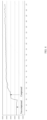
- FIG. 4 shows a capacitance value variation diagram of a continuous glucose monitor when being non-compressed and when being compressed provided in an embodiment of the present disclosure.
- the auxiliary sensor 104 inside the continuous glucose monitor 100 is a capacitive sensor.
- abscissas in the figure represent sampling points (33 sampling points per second), and ordinates represent capacitance values.
- the continuous glucose monitor 100 Before the 100th sampling point, the continuous glucose monitor 100 is not compressed, and the capacitance value of the capacitive sensor is in a stable state. After the 100th sampling point, the continuous glucose monitor 100 is subjected to compression, and the capacitance value of the capacitive sensor is significantly increased. Therefore, the capacitance value changes of the capacitive sensor can be detected to identify the compressed state of the continuous glucose monitor 100.
- a capacitive sensor is additionally provided in the continuous glucose monitor 100, to identify the compressed state of the continuous glucose monitor 100 using the characteristic that the capacitance of the capacitive sensor is increased in the compressed state, and then provide the compressed state information to a MCU or a host computer, so that the MCU or the host computer can compensate for and correct the glucose measurement result based on the compressed state information, thereby improving the accuracy of glucose measurement.
Landscapes
- Health & Medical Sciences (AREA)
- Life Sciences & Earth Sciences (AREA)
- Physics & Mathematics (AREA)
- Biomedical Technology (AREA)
- Medical Informatics (AREA)
- Biophysics (AREA)
- Pathology (AREA)
- Engineering & Computer Science (AREA)
- Veterinary Medicine (AREA)
- Heart & Thoracic Surgery (AREA)
- Public Health (AREA)
- Molecular Biology (AREA)
- Surgery (AREA)
- Animal Behavior & Ethology (AREA)
- General Health & Medical Sciences (AREA)
- Optics & Photonics (AREA)
- Emergency Medicine (AREA)
- Measurement Of The Respiration, Hearing Ability, Form, And Blood Characteristics Of Living Organisms (AREA)
Abstract
Description
- The present disclosure relates to the technical field of glucose monitoring, and more particularly relates to a continuous glucose monitor.
- A continuous glucose monitor (CGM) is a glucose measuring device that continuously measures glucose concentration in blood through a subcutaneously implanted sensor, and can provide a user with continuous and dynamic glucose data. Compared with conventional glucose monitoring, which requires sampling fingertip blood for measurement, the CGM not only can greatly improve life experience of diabetics, but also can provide more complete and more dynamic glucose data, thus providing more basis for medication and treatment of the diabetics. The CGM is generally implanted on an outer side of an arm. When a user is sleeping, the CGM will be compressed in some sleeping postures (such as side lying), thereby resulting in poor circulation of blood and tissue fluid in the arm, and sharply increasing glucose measurement errors.
- Therefore, how to identify a compressed state of the CGM to improve accuracy of glucose measurement is a technical problem to be urgently solved.
- A continuous glucose monitor provided in a first aspect of embodiments of the present disclosure comprises:
- a housing and a circuit board arranged in the housing, wherein an electronic component is carried on the circuit board;
- a probe assembly configured to penetrate skin and connected to the circuit board; and
- an auxiliary sensor connected to the circuit board and configured to detect a compressed state of the continuous glucose monitor.
- In a possible embodiment, the auxiliary sensor is a capacitive sensor, and when the capacitive sensor is subjected to compression, a capacitance value detected by the capacitive sensor will change.
- In a possible embodiment, the auxiliary sensor is a pressure sensor, and when the pressure sensor is subjected to compression, a pressure value detected by the pressure sensor will change.
- In a possible embodiment, the capacitive sensor is arranged in the housing, and is electrically connected to the circuit board.
- In a possible embodiment, the probe assembly comprises a probe that extends to outside through an opening at one end of the housing.
- In a possible embodiment, the capacitive sensor and the probe assembly are arranged on a same surface of the circuit board.
- In a possible embodiment, the capacitive sensor and the probe assembly are arranged on different surfaces of the circuit board.
- In a possible embodiment, the capacitive sensor is arranged on a side edge of the circuit board, and the probe assembly is arranged on a lower surface of the circuit board.
- In a possible embodiment, the circuit board is a printed circuit board.
- In a possible embodiment, the electronic component comprises a microcontroller unit.
- The embodiments of the present disclosure provide a continuous glucose monitor, which can identify its own compressed state, thereby improving the accuracy of blood glucose measurement.
-
-
FIG. 1 is a schematic structural diagram of a continuous glucose monitor provided in an embodiment of the present disclosure. -
FIG. 2 is a schematic diagram of a body posture of a user. -
FIG. 3 is a schematic diagram of another body posture of a user. -
FIG. 4 is a capacitance value variation diagram of a continuous glucose monitor when being non-compressed and when being compressed provided in an embodiment of the present disclosure. - Technical solutions of embodiments of the present disclosure will be clearly and completely described below with reference to the drawings.
- The terms used in the present disclosure are intended merely to describe particular embodiments, and are not intended to limit the present disclosure. The singular forms of "a" and "the" used in the present disclosure and the appended claims are also intended to include plural forms, unless the context clearly indicates other meanings.
- In addition, the terms such as "first" and "second" are only used for distinguishing between similar objects, and cannot be understood as indicating or implying relative importance or implicitly indicating the number of indicated technical features. Thus, features defined with "first," "second," or the like may explicitly or implicitly include one or more of the features.
-
FIG. 1 shows a schematic structural diagram of a continuous glucose monitor provided in an embodiment of the present disclosure. - As shown in
FIG. 1 , thecontinuous glucose monitor 100 comprises ahousing 101 and acircuit board 102 arranged in the housing, wherein an electronic component is provided in thecircuit board 102; - a
probe assembly 103 configured to penetrate skin, theprobe assembly 103 being connected to thecircuit board 102; and - an
auxiliary sensor 104 connected to thecircuit board 102, theauxiliary sensor 104 being configured to detect a compressed state of thecontinuous glucose monitor 100. - The continuous glucose monitor 100 in an embodiment of the present disclosure can identify its own compressed state, thereby improving the accuracy of glucose measurement.
- Optionally, the
circuit board 102 may be a printed circuit board (PCB). The printed circuit board not only can be electrically connected to theprobe assembly 103 and theauxiliary sensor 104, but also can play a certain supporting role for theprobe assembly 103 and theauxiliary sensor 104. - As an optional embodiment, the electronic component carried on the
circuit board 102 includes a microcontroller unit (MCU). After detecting that thecontinuous glucose monitor 100 is in the compressed state, theauxiliary sensor 104 can transmit compressed state information to the microcontroller unit, and the microcontroller unit can compensate for and correct a blood glucose measurement result based on the received compressed state information to avoid occurrence of a very large measurement error, thereby improving the accuracy of glucose measurement. - As another optional embodiment, after detecting that the
continuous glucose monitor 100 is in the compressed state, theauxiliary sensor 104 can transmit the compressed state information to cloud software, and the cloud software can compensate for and correct a blood glucose measurement result based on the received compressed state information to avoid occurrence of a very large measurement error, thereby improving the accuracy of glucose measurement. - As an optional embodiment, the
auxiliary sensor 104 is a capacitive sensor, and when the capacitive sensor is subjected to compression, a capacitance value detected by the capacitive sensor will change. By detecting the capacitance value of the capacitive sensor, whether thecontinuous glucose monitor 100 is subjected to compression can be determined, and the information can be transmitted to the MCU or the cloud software to correct the glucose measurement result. - Optionally, the capacitive sensor is arranged in the
housing 101, and is electrically connected to thecircuit board 102. Thehousing 101 can provide certain support and protection for the capacitive sensor arranged therein. Preferably, the capacitive sensor is arranged inside thehousing 101 on one side close to skin during use by a user, so that the capacitive sensor can achieve better capacitance detection effects in most usage scenarios. - Optionally, the electronic component carried on the
circuit board 102 further comprises a capacitance detection chip, and the capacitive sensor can be connected to the capacitance detection chip on thecircuit board 102 through leads. - Optionally, referring to
FIG. 1 , theprobe assembly 103 comprises aprobe 1031, theprobe 1031 extends to the outside through anopening 105 at one end of thehousing 101, so that theprobe 1031 can be very easily implanted under the skin. - As an optional embodiment, the capacitive sensor and the
probe assembly 103 are arranged on a same surface of thecircuit board 102. When the user uses thecontinuous glucose monitor 100, the side where theprobe assembly 103 is located is the side close to the user's skin, and the capacitive sensor and theprobe assembly 103 are arranged on the same surface of thecircuit board 102, so that the capacitive sensor is also arranged on the side close to the user's skin, thereby achieving better capacitance detection effects in most usage scenarios during use, e.g., on an arm or an abdominal surface. - As another optional embodiment, the capacitive sensor and the
probe assembly 103 are arranged on different surfaces of thecircuit board 102. In this embodiment, when the user uses thecontinuous glucose monitor 100, the side where theprobe assembly 103 is located is still the side close to the user's skin, but the capacitive sensor is arranged on one side away from the user's skin. Such an arrangement can achieve better capacitance detection effects in some particular usage scenarios during use, e.g., at an underarm site or an intercrural site. - As another optional embodiment, the capacitive sensor is arranged on a side edge of the
circuit board 102, and theprobe assembly 103 is arranged on a lower surface of thecircuit board 102. Based on different product designs, the capacitive sensor can be arranged on the side edge of thecircuit board 102, thereby reducing the thickness of thecontinuous glucose monitor 100, and improving the user experience. - As an optional embodiment, the
auxiliary sensor 104 is a pressure sensor, and when the pressure sensor is subjected to compression, a pressure value detected by the pressure sensor will change. By detecting the pressure value of the pressure sensor, whether thecontinuous glucose monitor 100 is subjected to compression can be determined, and the information can be transmitted to the MCU or the cloud software to correct the glucose measurement result. - It is worth noting that the relevant settings for the capacitive sensor in the embodiments of the present disclosure can also be used for the pressure sensor.
-
FIG. 2 shows a schematic diagram of a body posture of a user. - As shown in
FIG. 2 , after the user normally wears thecontinuous glucose monitor 100 on his arm, if the user is in a body posture, such as standing, sitting, or flat lying, thecontinuous glucose monitor 100 will not be compressed. When theauxiliary sensor 104 is a capacitive sensor, in this case, a signal sensed by the capacitive sensor is a capacitance value formed between the capacitive sensor and user'sskin 200. -
FIG. 3 shows a schematic diagram of another body posture of a user. - As shown in
FIG. 3 , after the user normally wears the continuous glucose monitor 100 on his arm, if the user is in a body posture of side lying, the continuous glucose monitor 100 will sink into the user'sskin 200 because the skin on the arm is soft, thereby producing the effect of being wrapped. When theauxiliary sensor 104 is a capacitive sensor, in this case, the capacitance value formed between the capacitive sensor and the user'sskin 200 will be significantly increased. This feature can be used to implement compression detection of thecontinuous glucose monitor 100. -
FIG. 4 shows a capacitance value variation diagram of a continuous glucose monitor when being non-compressed and when being compressed provided in an embodiment of the present disclosure. Theauxiliary sensor 104 inside the continuous glucose monitor 100 is a capacitive sensor. - As shown in
FIG. 4 , abscissas in the figure represent sampling points (33 sampling points per second), and ordinates represent capacitance values. Before the 100th sampling point, the continuous glucose monitor 100 is not compressed, and the capacitance value of the capacitive sensor is in a stable state. After the 100th sampling point, the continuous glucose monitor 100 is subjected to compression, and the capacitance value of the capacitive sensor is significantly increased. Therefore, the capacitance value changes of the capacitive sensor can be detected to identify the compressed state of thecontinuous glucose monitor 100. - In a preferred embodiment of the present disclosure, a capacitive sensor is additionally provided in the continuous glucose monitor 100, to identify the compressed state of the continuous glucose monitor 100 using the characteristic that the capacitance of the capacitive sensor is increased in the compressed state, and then provide the compressed state information to a MCU or a host computer, so that the MCU or the host computer can compensate for and correct the glucose measurement result based on the compressed state information, thereby improving the accuracy of glucose measurement.
- The preferred embodiments of the present disclosure are described in detail above with reference to the drawings. However, the present disclosure is not limited to the specific details of the above-mentioned embodiments. Within the scope of the technical concept of the present disclosure, multiple simple modifications can be made to the technical solutions of the present disclosure, and the simple modifications are all encompassed within the scope of protection of the present disclosure.
Claims (10)
- A continuous glucose monitor, comprising:a housing and a circuit board arranged in the housing, wherein an electronic component is carried on the circuit board;a probe assembly configured to penetrate skin and connected to the circuit board; andan auxiliary sensor connected to the circuit board and configured to detect a compressed state of the continuous glucose monitor.
- The continuous glucose monitor according to claim 1, wherein the auxiliary sensor is a capacitive sensor, and when the capacitive sensor is subjected to compression, a capacitance value detected by the capacitive sensor changes.
- The continuous glucose monitor according to claim 1, wherein the auxiliary sensor is a pressure sensor, and when the pressure sensor is subjected to compression, a pressure value detected by the pressure sensor changes.
- The continuous glucose monitor according to claim 2, wherein the capacitive sensor is arranged in the housing, and is electrically connected to the circuit board.
- The continuous glucose monitor according to claim 4, wherein the probe assembly comprises a probe that extends to outside through an opening at one end of the housing.
- The continuous glucose monitor according to claim 5, wherein the capacitive sensor and the probe assembly are arranged on a same surface of the circuit board.
- The continuous glucose monitor according to claim 5, wherein the capacitive sensor and the probe assembly are arranged on different surfaces of the circuit board.
- The continuous glucose monitor according to claim 5, wherein the capacitive sensor is arranged on a side edge of the circuit board, and the probe assembly is arranged on a lower surface of the circuit board.
- The continuous glucose monitor according to any one of claims 1 to 8, wherein the circuit board is a printed circuit board.
- The continuous glucose monitor according to any one of claims 1 to 8, wherein the electronic component comprises a microcontroller unit.
Applications Claiming Priority (1)
| Application Number | Priority Date | Filing Date | Title |
|---|---|---|---|
| CN202311068111.1A CN117045247A (en) | 2023-08-23 | 2023-08-23 | A continuous blood glucose monitoring device |
Publications (1)
| Publication Number | Publication Date |
|---|---|
| EP4512325A1 true EP4512325A1 (en) | 2025-02-26 |
Family
ID=88658635
Family Applications (1)
| Application Number | Title | Priority Date | Filing Date |
|---|---|---|---|
| EP24195633.3A Withdrawn EP4512325A1 (en) | 2023-08-23 | 2024-08-21 | Continuous glucose monitor |
Country Status (3)
| Country | Link |
|---|---|
| US (1) | US20250064350A1 (en) |
| EP (1) | EP4512325A1 (en) |
| CN (1) | CN117045247A (en) |
Families Citing this family (2)
| Publication number | Priority date | Publication date | Assignee | Title |
|---|---|---|---|---|
| WO2025256649A1 (en) * | 2024-06-14 | 2025-12-18 | 深圳硅基传感科技有限公司 | Sensor control apparatus and related calibration method |
| CN118969246A (en) * | 2024-07-29 | 2024-11-15 | 上海联影微电子科技有限公司 | Data correction method, device and computer equipment |
Citations (3)
| Publication number | Priority date | Publication date | Assignee | Title |
|---|---|---|---|---|
| US20180279928A1 (en) * | 2011-04-15 | 2018-10-04 | Dexcom, Inc. | Advanced analyte sensor calibration and error detection |
| US20190339224A1 (en) * | 2018-05-03 | 2019-11-07 | Dexcom, Inc. | Automatic analyte sensor calibration and error detection |
| US20210228114A1 (en) * | 2020-01-23 | 2021-07-29 | Waveform Technologies, Inc. | Adjunct data to improve the performance of a continuous glucose monitoring system |
Family Cites Families (3)
| Publication number | Priority date | Publication date | Assignee | Title |
|---|---|---|---|---|
| EP4333325B1 (en) * | 2010-09-29 | 2026-02-25 | Dexcom, Inc. | Advanced continuous analyte monitoring system |
| JP7059194B2 (en) * | 2016-03-30 | 2022-04-25 | デックスコム・インコーポレーテッド | System for sample monitoring system |
| CN221308195U (en) * | 2023-08-23 | 2024-07-12 | 深圳市汇顶科技股份有限公司 | Continuous blood sugar monitoring device |
-
2023
- 2023-08-23 CN CN202311068111.1A patent/CN117045247A/en active Pending
-
2024
- 2024-08-19 US US18/808,501 patent/US20250064350A1/en active Pending
- 2024-08-21 EP EP24195633.3A patent/EP4512325A1/en not_active Withdrawn
Patent Citations (3)
| Publication number | Priority date | Publication date | Assignee | Title |
|---|---|---|---|---|
| US20180279928A1 (en) * | 2011-04-15 | 2018-10-04 | Dexcom, Inc. | Advanced analyte sensor calibration and error detection |
| US20190339224A1 (en) * | 2018-05-03 | 2019-11-07 | Dexcom, Inc. | Automatic analyte sensor calibration and error detection |
| US20210228114A1 (en) * | 2020-01-23 | 2021-07-29 | Waveform Technologies, Inc. | Adjunct data to improve the performance of a continuous glucose monitoring system |
Also Published As
| Publication number | Publication date |
|---|---|
| US20250064350A1 (en) | 2025-02-27 |
| CN117045247A (en) | 2023-11-14 |
Similar Documents
| Publication | Publication Date | Title |
|---|---|---|
| US20250064350A1 (en) | Continuous glucose monitor | |
| EP3469983B1 (en) | Portable smart health monitoring device | |
| CN105873514B (en) | Dynamic glucose harvester and host | |
| US10722125B2 (en) | Blood pressure signal acquisition using a pressure sensor array | |
| US20070185409A1 (en) | Method and system for determining an operable stimulus intensity for nerve conduction testing | |
| CN105722454A (en) | Pregnancy monitoring system and method | |
| EP2329764A3 (en) | Device for determining the glucose level in body tissue | |
| US20160206224A1 (en) | Ecg electrode snap connector and associated methods | |
| JP2010536469A (en) | Skin penetration detection system and method | |
| CN221308195U (en) | Continuous blood sugar monitoring device | |
| US20180344213A1 (en) | Biological information measurement device, personal identification device, and personal identification method | |
| TWI729387B (en) | Wearable device for physiological data detection | |
| CN1293943A (en) | Dynamic hemomanometer and its measuring method | |
| CN222091672U (en) | Detection components and electronic equipment | |
| EP3880065A2 (en) | Handheld ecg monitoring system with fault detection | |
| CN204557396U (en) | A kind of human body physiological parameter detects mouse | |
| CN115804595B (en) | Glucose monitoring system for glucose concentration levels before and after sleep | |
| CN221411209U (en) | A continuous blood glucose monitoring system | |
| CN209252850U (en) | A multifunctional blood pressure measuring instrument | |
| US20170164856A1 (en) | Sensing of a user's physiological context using a hand-held device | |
| JP7861531B2 (en) | Biological information measuring device, control method and program for biological information measuring device | |
| CN111603156B (en) | Method for improving effective electrocardiograph measurement and electrocardiograph measurement device thereof | |
| CN223246606U (en) | Electronic equipment | |
| US20260033783A1 (en) | Detection of signal variations due to pressure on analyte sensor | |
| TWI507171B (en) | Physiological signal measuring device, measuring system and data processing method |
Legal Events
| Date | Code | Title | Description |
|---|---|---|---|
| PUAI | Public reference made under article 153(3) epc to a published international application that has entered the european phase |
Free format text: ORIGINAL CODE: 0009012 |
|
| STAA | Information on the status of an ep patent application or granted ep patent |
Free format text: STATUS: REQUEST FOR EXAMINATION WAS MADE |
|
| 17P | Request for examination filed |
Effective date: 20240821 |
|
| AK | Designated contracting states |
Kind code of ref document: A1 Designated state(s): AL AT BE BG CH CY CZ DE DK EE ES FI FR GB GR HR HU IE IS IT LI LT LU LV MC ME MK MT NL NO PL PT RO RS SE SI SK SM TR |
|
| STAA | Information on the status of an ep patent application or granted ep patent |
Free format text: STATUS: EXAMINATION IS IN PROGRESS |
|
| 17Q | First examination report despatched |
Effective date: 20260330 |
|
| STAA | Information on the status of an ep patent application or granted ep patent |
Free format text: STATUS: THE APPLICATION HAS BEEN WITHDRAWN |
|
| 18W | Application withdrawn |
Effective date: 20260630 |