EP4512316A1 - Biometric information measurement apparatus and electronic device - Google Patents
Biometric information measurement apparatus and electronic device Download PDFInfo
- Publication number
- EP4512316A1 EP4512316A1 EP23822225.1A EP23822225A EP4512316A1 EP 4512316 A1 EP4512316 A1 EP 4512316A1 EP 23822225 A EP23822225 A EP 23822225A EP 4512316 A1 EP4512316 A1 EP 4512316A1
- Authority
- EP
- European Patent Office
- Prior art keywords
- connecting plate
- blood pressure
- finger
- finger stall
- biometric information
- Prior art date
- Legal status (The legal status is an assumption and is not a legal conclusion. Google has not performed a legal analysis and makes no representation as to the accuracy of the status listed.)
- Pending
Links
Images



Classifications
-
- A—HUMAN NECESSITIES
- A61—MEDICAL OR VETERINARY SCIENCE; HYGIENE
- A61B—DIAGNOSIS; SURGERY; IDENTIFICATION
- A61B5/00—Measuring for diagnostic purposes; Identification of persons
- A61B5/02—Detecting, measuring or recording for evaluating the cardiovascular system, e.g. pulse, heart rate, blood pressure or blood flow
- A61B5/021—Measuring pressure in heart or blood vessels
- A61B5/022—Measuring pressure in heart or blood vessels by applying pressure to close blood vessels, e.g. against the skin; Ophthalmodynamometers
- A61B5/02233—Occluders specially adapted therefor
- A61B5/02241—Occluders specially adapted therefor of small dimensions, e.g. adapted to fingers
-
- A—HUMAN NECESSITIES
- A61—MEDICAL OR VETERINARY SCIENCE; HYGIENE
- A61B—DIAGNOSIS; SURGERY; IDENTIFICATION
- A61B5/00—Measuring for diagnostic purposes; Identification of persons
- A61B5/02—Detecting, measuring or recording for evaluating the cardiovascular system, e.g. pulse, heart rate, blood pressure or blood flow
- A61B5/021—Measuring pressure in heart or blood vessels
- A61B5/02108—Measuring pressure in heart or blood vessels from analysis of pulse wave characteristics
-
- A—HUMAN NECESSITIES
- A61—MEDICAL OR VETERINARY SCIENCE; HYGIENE
- A61B—DIAGNOSIS; SURGERY; IDENTIFICATION
- A61B5/00—Measuring for diagnostic purposes; Identification of persons
- A61B5/02—Detecting, measuring or recording for evaluating the cardiovascular system, e.g. pulse, heart rate, blood pressure or blood flow
- A61B5/021—Measuring pressure in heart or blood vessels
- A61B5/02141—Details of apparatus construction, e.g. pump units or housings therefor, cuff pressurising systems, arrangements of fluid conduits or circuits
-
- A—HUMAN NECESSITIES
- A61—MEDICAL OR VETERINARY SCIENCE; HYGIENE
- A61B—DIAGNOSIS; SURGERY; IDENTIFICATION
- A61B5/00—Measuring for diagnostic purposes; Identification of persons
- A61B5/02—Detecting, measuring or recording for evaluating the cardiovascular system, e.g. pulse, heart rate, blood pressure or blood flow
- A61B5/024—Measuring pulse rate or heart rate
- A61B5/02416—Measuring pulse rate or heart rate using photoplethysmograph signals, e.g. generated by infrared radiation
- A61B5/02427—Details of sensor
- A61B5/02433—Details of sensor for infrared radiation
-
- A—HUMAN NECESSITIES
- A61—MEDICAL OR VETERINARY SCIENCE; HYGIENE
- A61B—DIAGNOSIS; SURGERY; IDENTIFICATION
- A61B5/00—Measuring for diagnostic purposes; Identification of persons
- A61B5/02—Detecting, measuring or recording for evaluating the cardiovascular system, e.g. pulse, heart rate, blood pressure or blood flow
- A61B5/024—Measuring pulse rate or heart rate
- A61B5/02438—Measuring pulse rate or heart rate with portable devices, e.g. worn by the patient
-
- A—HUMAN NECESSITIES
- A61—MEDICAL OR VETERINARY SCIENCE; HYGIENE
- A61B—DIAGNOSIS; SURGERY; IDENTIFICATION
- A61B5/00—Measuring for diagnostic purposes; Identification of persons
- A61B5/145—Measuring characteristics of blood in vivo, e.g. gas concentration or pH-value ; Measuring characteristics of body fluids or tissues, e.g. interstitial fluid or cerebral tissue
- A61B5/1455—Measuring characteristics of blood in vivo, e.g. gas concentration or pH-value ; Measuring characteristics of body fluids or tissues, e.g. interstitial fluid or cerebral tissue using optical sensors, e.g. spectral photometrical oximeters
- A61B5/14551—Measuring characteristics of blood in vivo, e.g. gas concentration or pH-value ; Measuring characteristics of body fluids or tissues, e.g. interstitial fluid or cerebral tissue using optical sensors, e.g. spectral photometrical oximeters for measuring blood gases
- A61B5/14552—Details of sensors specially adapted therefor
-
- A—HUMAN NECESSITIES
- A61—MEDICAL OR VETERINARY SCIENCE; HYGIENE
- A61B—DIAGNOSIS; SURGERY; IDENTIFICATION
- A61B5/00—Measuring for diagnostic purposes; Identification of persons
- A61B5/68—Arrangements of detecting, measuring or recording means, e.g. sensors, in relation to patient
- A61B5/6801—Arrangements of detecting, measuring or recording means, e.g. sensors, in relation to patient specially adapted to be attached to or worn on the body surface
- A61B5/6813—Specially adapted to be attached to a specific body part
- A61B5/6825—Hand
- A61B5/6826—Finger
-
- A—HUMAN NECESSITIES
- A61—MEDICAL OR VETERINARY SCIENCE; HYGIENE
- A61B—DIAGNOSIS; SURGERY; IDENTIFICATION
- A61B5/00—Measuring for diagnostic purposes; Identification of persons
- A61B5/68—Arrangements of detecting, measuring or recording means, e.g. sensors, in relation to patient
- A61B5/6801—Arrangements of detecting, measuring or recording means, e.g. sensors, in relation to patient specially adapted to be attached to or worn on the body surface
- A61B5/683—Means for maintaining contact with the body
- A61B5/6838—Clamps or clips
-
- A—HUMAN NECESSITIES
- A61—MEDICAL OR VETERINARY SCIENCE; HYGIENE
- A61B—DIAGNOSIS; SURGERY; IDENTIFICATION
- A61B2560/00—Constructional details of operational features of apparatus; Accessories for medical measuring apparatus
- A61B2560/04—Constructional details of apparatus
- A61B2560/0406—Constructional details of apparatus specially shaped apparatus housings
-
- A—HUMAN NECESSITIES
- A61—MEDICAL OR VETERINARY SCIENCE; HYGIENE
- A61B—DIAGNOSIS; SURGERY; IDENTIFICATION
- A61B2560/00—Constructional details of operational features of apparatus; Accessories for medical measuring apparatus
- A61B2560/04—Constructional details of apparatus
- A61B2560/0462—Apparatus with built-in sensors
-
- A—HUMAN NECESSITIES
- A61—MEDICAL OR VETERINARY SCIENCE; HYGIENE
- A61B—DIAGNOSIS; SURGERY; IDENTIFICATION
- A61B2562/00—Details of sensors; Constructional details of sensor housings or probes; Accessories for sensors
- A61B2562/02—Details of sensors specially adapted for in-vivo measurements
- A61B2562/0247—Pressure sensors
-
- A—HUMAN NECESSITIES
- A61—MEDICAL OR VETERINARY SCIENCE; HYGIENE
- A61B—DIAGNOSIS; SURGERY; IDENTIFICATION
- A61B2562/00—Details of sensors; Constructional details of sensor housings or probes; Accessories for sensors
- A61B2562/16—Details of sensor housings or probes; Details of structural supports for sensors
- A61B2562/168—Fluid filled sensor housings
Definitions
- a first aspect of embodiments of the present disclosure provides an apparatus for detecting biometric information, including:
- the apparatus further includes a pressure detector electrically connected to the analog front end.
- the finger stall is a two-end through type finger stall with an annular cross section.
- the finger stall is a non-through type
- the finger stall further includes an air conduit connected to the gasbag.
- the mechanical structure includes a spring structure, where the spring structure includes a spring body and a connecting plate; and the connecting plate is connected to one end of the spring body, another end of the spring body is connected to the finger stall, and the spring structure is arranged on one side inside the finger stall close to the opening.
- the spring body includes a first spring body and a second spring body
- the connecting plate includes a first connecting plate and a second connecting plate
- the first connecting plate is connected to the first spring body
- the second connecting plate is connected to the second spring body
- the light emitter is arranged on the first connecting plate
- the photodiode is arranged on the second connecting plate.
- the mechanical structure or the gasbag is arranged on one side inside the finger stall close to the opening.
- the mechanical structure includes a motor structure, where the motor structure includes a motor and a connecting plate, the connecting plate is connected to the motor, the motor is configured to control movement of the connecting plate, and the motor structure is arranged on one side inside the finger stall close to the opening.
- the biometric information further includes at least one of a heart rate value and a blood oxygen value.
- a second aspect of the embodiments of the present disclosure provides an electronic device, including the apparatus for detecting biometric information provided in the first aspect of the embodiments of the present disclosure and a display screen arranged on an outer surface of the apparatus, where the display screen is configured to display the biometric information.
- the electronic device includes a smart ring, a finger clip-type blood pressure meter, a finger clip-type blood pressure oximeter, and a finger clip-type multi-parameter meter.
- Embodiments of the present disclosure provide an apparatus for detecting biometric information that can measure blood pressure based on a finger, and complete accurate blood pressure measurement in a small volume, thereby miniaturizing a blood pressure measuring apparatus, and facilitating offering portability for users.
- the embodiments of the present disclosure further provide an electronic device that can facilitate quickly and conveniently monitoring real-time blood pressure of hypertension users in a non-household environment, and improving the user experience.
- first and second are only used for distinguishing between similar objects, but cannot be understood as indicating or implying relative importance or implicitly indicating the number of indicated technical features.
- features defined with “first,” “second,” or the like may explicitly or implicitly include one or more of the features.
- FIG. 1 shows a schematic diagram of a finger blood vessel changing from diastole to systole, and then returning to diastole.
- a finger 10 includes a bone 101 and a blood vessel 102.
- the blood vessel 102 In the case when the finger 10 is in a normal resting state, the blood vessel 102 is in a diastolic state.
- the blood vessel 102 on either side of the finger 10 will gradually change from the diastolic state to a systolic state, as shown in FIG. 1(b) .
- blood flow in the blood vessel 102 will decrease to a nearly cutoff state.
- the blood vessel 102 will gradually restore from the systolic state to the diastolic state.
- a pressure value and a pressure pulse wave or a photoelectric pulse wave of the blood vessel 102 are recorded synchronously.
- a waveform of the pressure pulse wave and a waveform of the photoelectric pulse wave have similar morphological characteristics.
- the pressure pulse wave and the photoelectric pulse wave are actually two different manifestations of a same arterial periodic pulsation process, and therefore both essentially reflect a functional state of the cardiovascular system. Therefore, characteristics of pressure pulse wave or photoelectric pulse wave signals may be analyzed and studied, to extract physiological and pathological information contained therein, thus providing assistance for early diagnosis and prevention of cardiovascular system-related diseases.
- the pressure pulse wave is generally detected and acquired at superficial arteries such as radial artery, carotid artery, or femoral artery.
- a change curve of arterial pressure over time is photoplethysmographized using a pressure detector to obtain the waveform of the pressure pulse wave.
- the photoelectric pulse wave is generally detected and acquired using a photoelectric sensor, is therefore often referred to as photoelectric volume pulse wave, and is usually detected and obtained by photo plethysmography (PPG).
- PPG photo plethysmography
- a change curve of blood volume over time photoplethysmographized using this method is called the waveform of the photoelectric pulse wave, and is also abbreviated as PPG waveform below.
- a peak value of the PPG waveform is extracted based on the waveform of the pressure pulse wave or the photoelectric pulse wave during systole or diastole, to plot an envelope curve.
- a maximum amplitude is the Mean Blood Pressure (MBP)
- MBP Mean Blood Pressure
- a systolic blood pressure (SBP) and a diastolic blood pressure (DBP) can be obtained by conventional double Gaussian fitting, envelope bathmometry, or deep learning algorithm.
- FIG. 2 shows a schematic structural diagram of an apparatus for detecting biometric information provided in an embodiment of the present disclosure
- FIG. 3 shows a schematic structural diagram of another apparatus for detecting biometric information provided in an embodiment of the present disclosure
- FIG. 4 shows a schematic structural diagram of still another apparatus for detecting biometric information provided in an embodiment of the present disclosure.
- inventions of the present disclosure provide an apparatus 20 for detecting biometric information.
- the apparatus 20 includes: a finger stall 200, the finger stall 200 including a mechanical structure 24 or a gasbag 25, where the mechanical structure 24 or the gasbag 25 is configured to fix the finger stall 200 on a finger 10 of a user.
- the finger stall 200 is a two-end through type
- the two-end through type finger stall 202 has an annular cross section, including a circular annular shape, a triangular annular shape, a square annular shape, an elliptical annular shape, and a wavy annular shape.
- the finger stall 202 in FIG. 4 is similar to a ring.
- the user can wear the two-end through type finger stall 202 on a third knuckle (as shown in FIG. 4(a) ) or a second knuckle (as shown in FIG. 4(b) ) of the finger 10, to conveniently and quickly achieve blood pressure detection.
- the finger stall 200 is a non-through type. That is, the non-through type finger stall 201 is only provided with an opening at one end, a cross section of the non-through type finger stall 201 is one of rectangle, circle, ellipse, and polygon, and the non-through type finger stall 201 has an internal space for accommodating the finger 10 of the user. In daily use, the non-through type finger stall 201 is less affected by environmental light, thereby not only achieving highly accurate blood pressure detection, but also satisfying the requirements for convenience and high efficiency.
- the two-end through type finger stall 202 and the non-through type finger stall 201 may each include the mechanical structure 24 or the gasbag 25.
- the mechanical structure 24 or the gasbag 25 is arranged on one side inside the finger stall 200 close to the opening.
- the opening side of the non-through type finger stall 201 is close to the third knuckle of the finger 10, and the mechanical structure 24 or the gasbag 25 is arranged on one side inside the non-through type finger stall 201 close to the opening, to collect a waveform of a pressure pulse wave or a photoelectric pulse wave at the third knuckle.
- the finger stall 200 includes the gasbag 25 and an air conduit 270, where the air conduit 270 is connected to the gasbag 25, and the air conduit 270 can inflate and deflate the gasbag 25.
- the finger stall 200 includes the mechanical structure 24, where the mechanical structure 24 is configured to fix the finger stall 200 on the finger 10 of the user.
- the mechanical structure 24 includes a spring structure 240, where the spring structure 240 includes a spring body 241 and a connecting plate 242.
- the connecting plate 242 is connected to one end of the spring body 241, another end of the spring body 241 is connected to the finger stall 200, and the spring structure 240 is arranged on one side inside the finger stall 200 close to the opening.
- the spring body 241 includes a first spring body 2411 and a second spring body 2412
- the connecting plate 242 includes a first connecting plate 2421 and a second connecting plate 2422
- the first connecting plate 2421 is connected to the first spring body 2411
- the second connecting plate 2422 is connected to the second spring body 2412
- a light emitter 211 is arranged on the first connecting plate 2421
- a photodiode 212 is arranged on the second connecting plate 2422.
- the mechanical structure 24 includes a motor structure, where the motor structure includes a motor and a connecting plate, the connecting plate is connected to the motor, the motor is configured to control movement of the connecting plate, and the motor structure is arranged on one side inside the finger stall 200 close to the opening.
- the motor can control the connecting plate to perform systolic and diastolic operations on the blood vessel 102.
- a pulse wave sensor 210 including the light emitter 211 and the photodiode 212, where the light emitter 211 is configured to emit a light signal which reaches the photodiode 212 after being reflected or transmitted by a to-be-detected object, and the photodiode 212 is configured to convert the received light signal into an electrical signal.
- the light signal emitted from the light emitter 211 is received by the photodiode 212 through muscles, bones, veins, and other connecting tissues of the finger 10.
- the reflection-type pulse wave sensor 210 in the reflection-type pulse wave sensor 210, the light signal emitted from the light emitter 211 is reflected to the photodiode 212 through skin tissues of the finger 10.
- An analog front end (AFE) 220 the analog front end 220 being electrically connected to the pulse wave sensor 210, the analog front end 220 being configured to receive the electrical signal and output an analog front end signal.
- the analog front end 220 can perform, e.g., amplification, filtering, and analog-to-digital (AD) conversion on the electrical signal sensed by the pulse wave sensor 210, and the processed signal is the analog front end signal.
- AD analog-to-digital
- a microcontroller unit (MCU) 230 the microcontroller unit 230 being electrically connected to the analog front end 220, the microcontroller unit 230 being configured to receive the analog front end signal and output the biometric information, the biometric information including a blood pressure value.
- the microcontroller unit can process the analog front end signal by conventional double Gaussian fitting, envelope bathmometry, or deep learning algorithm, and then obtain a blood pressure value including a systolic blood pressure (SBP) and a diastolic blood pressure (DBP).
- SBP systolic blood pressure
- DBP diastolic blood pressure
- the biometric information further includes at least one of a heart rate value and a blood oxygen value.
- the pulse wave sensor 210 can be used for both blood pressure detection, and heart rate and blood oxygen detection, thereby achieving multiplexing of the pulse wave sensor 210, simplifying the structure of the apparatus 20, and saving costs.
- the apparatus 20 further comprises a pressure detector 260, where the pressure detector 260 is electrically connected to the analog front end 220.
- the pressure detector 260 can be configured to measure the pressure pulse wave, and then compute the blood pressure value based on the pressure pulse wave, while the pulse wave sensor 210 will be configured to measure the heart rate value and the blood oxygen value.
- the pressure detector 260 and the pulse wave sensor 210 can be combined to measure the blood pressure value, and two initial blood pressure values can be computed based on the pressure pulse wave measured by the pressure detector 260 and the photoelectric pulse wave measured by the pulse wave sensor 210, respectively. Then, the two initial blood pressure values can be processed, e.g., by averaging to obtain a target blood pressure value.
- the blood pressure value is computed using both the pressure detector 260 and the pulse wave sensor 210, thereby improving the accuracy of the computation result of the blood pressure value.
- the pressure detector 260 not only can be applied to the apparatus in FIG. 3 and FIG. 4 , but also can be applied to the apparatus 20 in FIG. 2 .
- the scope of application of the pressure detector 260 is not limited in the embodiments of the present disclosure.
- FIG. 5 is a PPG waveform amplitude curve of a blood vessel in a process of changing from complete systole to recovery of diastole.
- the photoelectric pulse wave amplitude curve is acquired by applying a pressure to the finger 10 to achieve a process of blocking the blood vessel 102.
- Multi-dimensional curve features are acquired by curve fitting to acquire a final blood pressure result, namely the systolic blood pressure (SBP) and the diastolic blood pressure (DBP) in FIG. 5 , based on curve fitting parameters (Parameter 1, Parameter 2, Parameter 3, ... in FIG. 5 ).
- SBP systolic blood pressure
- DBP diastolic blood pressure
- a pressure corresponding to maximum change of the blood vessel volume is the mean blood pressure (MBP), and then an internal relationship between the systolic blood pressure (SBP), the diastolic blood pressure (DBP), and the mean blood pressure (MBP) is determined based on envelope curve features, to finally obtain the blood pressure result.
- SBP systolic blood pressure
- DBP diastolic blood pressure
- MBP mean blood pressure
- FIG. 6 is a schematic diagram of computing blood pressure by double Gaussian fitting.
- A1 and B1 are an ordinate and an abscissa of a peak point of the envelope curve respectively
- A2 is an ordinate of an intersection point of the envelope curve and the y-axis
- B2 is a difference between an abscissa of a point that is located to the left of the peak point and is half the height of the peak point on the envelope curve (that can be called the left half height point) and the abscissa of the peak point
- B3 is a difference between an abscissa of a point that is located to the right of the peak point and is half the height of the peak point on the envelope curve (that can be called the right half height point) and the abscissa of the peak point.
- DBP diastolic blood pressure
- SBP systolic blood pressure
- MBP mean blood pressure
- the blood pressure can be computed not only by the above-mentioned double Gaussian fitting, but also selectively by envelope bathmometry.
- the principle of the envelope bathmometry is that: an artery has highest elasticity under zero transmural pressure conditions, and two inflection points are located to the left and to the right of the peak point of the envelope curve of the pressure pulse wave. Cuff pressures corresponding to the two inflection points are the systolic blood pressure (SBP) and the diastolic blood pressure (DBP), respectively.
- SBP systolic blood pressure
- DBP diastolic blood pressure
- the inflection points correspond to largest pressure changes, so that an absolute value of a first derivative of the corresponding envelope curve is a maximum value. In this case, a value of a second derivative of the corresponding envelope curve should be 0.
- the two inflection points to the left and to the right of the peak point of the envelope curve can be found by computing the value of the first derivative or the value of the second derivative of the envelope curve of the pressure pulse wave, thereby computing the systolic blood pressure (SBP) and the diastolic blood pressure (DBP) respectively.
- SBP systolic blood pressure
- DBP diastolic blood pressure
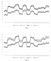
- FIG. 7 and FIG. 8 are a schematic diagram of a blood pressure detection result detected at a third knuckle of a finger via an apparatus for detecting biometric information provided in an embodiment of the present disclosure and a schematic diagram of a blood pressure detection result detected at a second knuckle of a finger via an apparatus for detecting biometric information provided in an embodiment of the present disclosure, respectively.
- the abscissas represent different tested objects, while the ordinates represent sizes of blood pressure values (mmHg).
- SBP0 and DBP0 represent real values of the systolic blood pressure and the diastolic blood pressure recorded using a mercury stethoscope
- SBP1 and DBP1 represent values of the systolic blood pressure and the diastolic blood pressure computed by collecting a pressure pulse wave at a fingertip.
- the blood pressure detection results at the third knuckle and the second knuckle are very close to the blood pressure detection results recorded using a mercury stethoscope. Therefore, it is feasible to perform blood pressure detection at the third knuckle and the second knuckle.
- blood pressure measurement is performed on 25 subjects at different sites such as the arm, wrist, third knuckle, and second knuckle by collecting pressure pulse waves via oscillography, by envelope fitting via extraction of peaks of the pressure pulse waves, and finally by computing a correlation coefficient among the envelope peak (EP) and the systolic blood pressure (SBP), the diastolic blood pressure (DBP), and the mean arterial pressure (MAP).
- Table 1 Position Normal blood pressure (15 people) Hypertension (10 people) SBP vs. EP DBP vs. EP MAP vs. EP SBP vs. EP DBP vs. EP MAP vs.
- the correlation coefficient among the systolic blood pressure (SBP), the diastolic blood pressure (DBP), and the mean arterial pressure (MAP) measured at the arm, wrist, third knuckle, and second knuckle and the envelope peak EP is strongly correlated with blood pressures at the third knuckle and the second knuckle, no matter for subjects with normal blood pressure or for subjects with hypertension.
- the MD represents a median deviation (MD)
- SD represents a standard deviation (SD).
- the accuracy evaluation results of the blood pressure data measured at the third knuckle and the second knuckle can be seen from Table 2.
- an absolute value of a median deviation (SBP_MD) of the systolic blood pressure (SBP) and an absolute value of a median deviation (DBP_MD) of the diastolic blood pressure (DBP) are each less than 5, and an absolute value of a standard deviation (SBP_SD) of the systolic blood pressure (SBP) and an absolute value of a standard deviation (DBP_SD) of the diastolic blood pressure (DBP) are each less than 8, complying with the ISO medical standard.
- the apparatus 20 for detecting biometric information provided in the embodiments of the present disclosure measures blood pressure at the third knuckle and the second knuckle, and the accuracy of the obtained blood pressure data is up to standard.
- FIG. 9 is a structural block diagram of an electronic device provided in an embodiment of the present disclosure.
- the embodiment of the present disclosure further provides an electronic device 40.
- the electronic device 40 includes the apparatus 20 for detecting biometric information provided in the above embodiments of the present disclosure and a display screen 30, where the display screen 30 is arranged on an outer surface of the apparatus 20, and the display screen 30 is configured to display the biometric information.
- the biometric information displayed on the display screen 30 includes a blood pressure value, a blood oxygen value, and a heart rate value.
- the display screen 30 can display the blood pressure value separately, or can display the blood pressure value, the blood oxygen value, and the heart rate value simultaneously.
- the wearable device further includes a portable blood pressure measuring device, such as a smart ring, a finger clip-type blood pressure meter, a finger clip-type blood pressure oximeter, and a finger clip-type multi-parameter meter.
- a portable blood pressure measuring device such as a smart ring, a finger clip-type blood pressure meter, a finger clip-type blood pressure oximeter, and a finger clip-type multi-parameter meter.
- FIG. 10 is a schematic diagram of an electronic device provided in an embodiment of the present disclosure.
- the electronic device 40 is a multifunctional finger clip-type blood pressure oximeter, which can measure the biometric information, such as a heart rate value, a blood oxygen value, a heart rate variability (HRV), and a blood pressure value.
- biometric information such as a heart rate value, a blood oxygen value, a heart rate variability (HRV), and a blood pressure value.
- HRV heart rate variability
- the electronic device 40 in the embodiments of the present disclosure can facilitate quickly and conveniently monitoring real-time blood pressure of hypertension users in a non-household environment, and improve the user experience.
Landscapes
- Health & Medical Sciences (AREA)
- Life Sciences & Earth Sciences (AREA)
- Physics & Mathematics (AREA)
- Cardiology (AREA)
- Medical Informatics (AREA)
- Animal Behavior & Ethology (AREA)
- Pathology (AREA)
- Engineering & Computer Science (AREA)
- Biomedical Technology (AREA)
- Heart & Thoracic Surgery (AREA)
- Veterinary Medicine (AREA)
- Molecular Biology (AREA)
- Surgery (AREA)
- Biophysics (AREA)
- General Health & Medical Sciences (AREA)
- Public Health (AREA)
- Physiology (AREA)
- Vascular Medicine (AREA)
- Optics & Photonics (AREA)
- Spectroscopy & Molecular Physics (AREA)
- Dentistry (AREA)
- Ophthalmology & Optometry (AREA)
- Measuring Pulse, Heart Rate, Blood Pressure Or Blood Flow (AREA)
Abstract
Description
- The present disclosure relates to the technical field of wearable devices, and more specifically relates to an apparatus for detecting biometric information and an electronic device.
- At present, a mercury sphygmomanometer is a golden standard in the field of blood pressure measurement. The mercury sphygmomanometer requires a user to have certain professional knowledge, and can be dynamically regulated by the user according to actual situation of a testee, so that its test result is accurate and it is applicable to a wide range of people. Electronic sphygmomanometers available on the current market may not need to be used and operated by professional personnel, but the electronic sphygmomanometers cannot meet the needs of hypertension groups for real-time blood pressure management because their overall size is large and they are generally suitable for placement in households and are not portable.
- Therefore, how to miniaturize a blood pressure measuring apparatus, so that it facilitates offering portability for users, and achieves blood pressure monitoring in a non-household environment for the users, is a technical problem in urgent need of solution.
- A first aspect of embodiments of the present disclosure provides an apparatus for detecting biometric information, including:
- a finger stall comprising a mechanical structure or a gasbag, where the mechanical structure or the gasbag is configured to fix the finger stall on a finger of a user;
- a pulse wave sensor comprising a light emitter and a photodiode, where the light emitter is configured to emit a light signal which reaches the photodiode after being reflected or transmitted by a to-be-detected object, and the photodiode is configured to convert the received light signal into an electrical signal;
- an analog front end electrically connected to the pulse wave sensor and configured to receive the electrical signal and output an analog front end signal; and
- a microcontroller unit electrically connected to the analog front end and configured to receive the analog front end signal and output the biometric information, the biometric information including a blood pressure value.
- In a possible embodiment, the apparatus further includes a pressure detector electrically connected to the analog front end.
- In a possible embodiment, the finger stall is a two-end through type finger stall with an annular cross section.
- In a possible embodiment, the finger stall is a non-through type;
- the non-through type finger stall is only provided with an opening at one end; and
- a cross section of the non-through type finger stall is one of rectangle, circle, ellipse, and polygon, and the non-through type finger stall has an internal space for accommodating the finger of the user.
- In a possible embodiment, the finger stall further includes an air conduit connected to the gasbag.
- In a possible embodiment, the mechanical structure includes a spring structure, where the spring structure includes a spring body and a connecting plate; and
the connecting plate is connected to one end of the spring body, another end of the spring body is connected to the finger stall, and the spring structure is arranged on one side inside the finger stall close to the opening. - In a possible embodiment, the spring body includes a first spring body and a second spring body, and the connecting plate includes a first connecting plate and a second connecting plate; and
the first connecting plate is connected to the first spring body, the second connecting plate is connected to the second spring body, the light emitter is arranged on the first connecting plate, and the photodiode is arranged on the second connecting plate. - In a possible embodiment, the mechanical structure or the gasbag is arranged on one side inside the finger stall close to the opening.
- In a possible embodiment, the mechanical structure includes a motor structure, where the motor structure includes a motor and a connecting plate, the connecting plate is connected to the motor, the motor is configured to control movement of the connecting plate, and the motor structure is arranged on one side inside the finger stall close to the opening.
- In a possible embodiment, the biometric information further includes at least one of a heart rate value and a blood oxygen value.
- A second aspect of the embodiments of the present disclosure provides an electronic device, including the apparatus for detecting biometric information provided in the first aspect of the embodiments of the present disclosure and a display screen arranged on an outer surface of the apparatus, where the display screen is configured to display the biometric information.
- In a possible embodiment, the electronic device includes a smart ring, a finger clip-type blood pressure meter, a finger clip-type blood pressure oximeter, and a finger clip-type multi-parameter meter.
- Embodiments of the present disclosure provide an apparatus for detecting biometric information that can measure blood pressure based on a finger, and complete accurate blood pressure measurement in a small volume, thereby miniaturizing a blood pressure measuring apparatus, and facilitating offering portability for users.
- The embodiments of the present disclosure further provide an electronic device that can facilitate quickly and conveniently monitoring real-time blood pressure of hypertension users in a non-household environment, and improving the user experience.
-
-
FIG. 1 is a schematic diagram of a finger blood vessel changing from diastole to systole, and then returning to diastole. -
FIG. 2 is a schematic structural diagram of an apparatus for detecting biometric information provided in an embodiment of the present disclosure. -
FIG. 3 is a schematic structural diagram of another apparatus for detecting biometric information provided in an embodiment of the present disclosure. -
FIG. 4 is a schematic structural diagram of still another apparatus for detecting biometric information provided in an embodiment of the present disclosure. -
FIG. 5 is a PPG waveform amplitude curve of a blood vessel in a process of changing from complete systole to recovery of diastole. -
FIG. 6 is a schematic diagram of computing blood pressure by double Gaussian fitting. -
FIG. 7 is a schematic diagram of a blood pressure detection result detected at a third knuckle of a finger via an apparatus for detecting biometric information provided in an embodiment of the present disclosure. -
FIG. 8 is a schematic diagram of a blood pressure detection result detected at a second knuckle of a finger via an apparatus for detecting biometric information provided in an embodiment of the present disclosure. -
FIG. 9 is a structural block diagram of an electronic device provided in an embodiment of the present disclosure. -
FIG. 10 is a schematic diagram of an electronic device provided in an embodiment of the present disclosure. - Technical solutions of embodiments of the present disclosure will be clearly and completely described below with reference to the drawings.
- The terms used in the present disclosure are intended merely to describe particular embodiments, and are not intended to limit the present disclosure. The singular forms of "a" and "the" used in the present disclosure and the appended claims are also intended to include plural forms, unless the context clearly indicates other meanings.
- In addition, the terms such as "first" and "second" are only used for distinguishing between similar objects, but cannot be understood as indicating or implying relative importance or implicitly indicating the number of indicated technical features. Thus, features defined with "first," "second," or the like may explicitly or implicitly include one or more of the features.
-
FIG. 1 shows a schematic diagram of a finger blood vessel changing from diastole to systole, and then returning to diastole. - As shown in
FIG. 1(a) , afinger 10 includes abone 101 and ablood vessel 102. In the case when thefinger 10 is in a normal resting state, theblood vessel 102 is in a diastolic state. When a pressure is applied to thefinger 10, theblood vessel 102 on either side of thefinger 10 will gradually change from the diastolic state to a systolic state, as shown inFIG. 1(b) . In this case, blood flow in theblood vessel 102 will decrease to a nearly cutoff state. Then, in the case when the pressure applied to thefinger 10 is gradually released, as shown inFIG. 1(c) , theblood vessel 102 will gradually restore from the systolic state to the diastolic state. - In the case when the
blood vessel 102 is systolic or theblood vessel 102 is diastolic, a pressure value and a pressure pulse wave or a photoelectric pulse wave of theblood vessel 102 are recorded synchronously. - A waveform of the pressure pulse wave and a waveform of the photoelectric pulse wave have similar morphological characteristics. The pressure pulse wave and the photoelectric pulse wave are actually two different manifestations of a same arterial periodic pulsation process, and therefore both essentially reflect a functional state of the cardiovascular system. Therefore, characteristics of pressure pulse wave or photoelectric pulse wave signals may be analyzed and studied, to extract physiological and pathological information contained therein, thus providing assistance for early diagnosis and prevention of cardiovascular system-related diseases.
- The pressure pulse wave is generally detected and acquired at superficial arteries such as radial artery, carotid artery, or femoral artery. A change curve of arterial pressure over time is photoplethysmographized using a pressure detector to obtain the waveform of the pressure pulse wave. The photoelectric pulse wave is generally detected and acquired using a photoelectric sensor, is therefore often referred to as photoelectric volume pulse wave, and is usually detected and obtained by photo plethysmography (PPG). A change curve of blood volume over time photoplethysmographized using this method is called the waveform of the photoelectric pulse wave, and is also abbreviated as PPG waveform below.
- Relevant features, such as a peak value of the PPG waveform, are extracted based on the waveform of the pressure pulse wave or the photoelectric pulse wave during systole or diastole, to plot an envelope curve. According to the principle of oscillography, a maximum amplitude is the Mean Blood Pressure (MBP), and then, a systolic blood pressure (SBP) and a diastolic blood pressure (DBP) can be obtained by conventional double Gaussian fitting, envelope bathmometry, or deep learning algorithm.
- Specifically,
FIG. 2 shows a schematic structural diagram of an apparatus for detecting biometric information provided in an embodiment of the present disclosure,FIG. 3 shows a schematic structural diagram of another apparatus for detecting biometric information provided in an embodiment of the present disclosure, andFIG. 4 shows a schematic structural diagram of still another apparatus for detecting biometric information provided in an embodiment of the present disclosure. - As shown in
FIG. 2, FIG. 3 , andFIG. 4 , embodiments of the present disclosure provide anapparatus 20 for detecting biometric information. Theapparatus 20 includes:
afinger stall 200, thefinger stall 200 including amechanical structure 24 or agasbag 25, where themechanical structure 24 or thegasbag 25 is configured to fix thefinger stall 200 on afinger 10 of a user. - Optionally, referring to
FIG. 4 , thefinger stall 200 is a two-end through type, and the two-end throughtype finger stall 202 has an annular cross section, including a circular annular shape, a triangular annular shape, a square annular shape, an elliptical annular shape, and a wavy annular shape. Thefinger stall 202 inFIG. 4 is similar to a ring. The user can wear the two-end throughtype finger stall 202 on a third knuckle (as shown inFIG. 4(a) ) or a second knuckle (as shown inFIG. 4(b) ) of thefinger 10, to conveniently and quickly achieve blood pressure detection. - Optionally, referring to
FIG. 2 and FIG. 3 , thefinger stall 200 is a non-through type. That is, the non-throughtype finger stall 201 is only provided with an opening at one end, a cross section of the non-throughtype finger stall 201 is one of rectangle, circle, ellipse, and polygon, and the non-throughtype finger stall 201 has an internal space for accommodating thefinger 10 of the user. In daily use, the non-throughtype finger stall 201 is less affected by environmental light, thereby not only achieving highly accurate blood pressure detection, but also satisfying the requirements for convenience and high efficiency. - In the embodiment of the present disclosure, the two-end through
type finger stall 202 and the non-throughtype finger stall 201 may each include themechanical structure 24 or thegasbag 25. - Optionally, the
mechanical structure 24 or thegasbag 25 is arranged on one side inside thefinger stall 200 close to the opening. - When the non-through
type finger stall 201 is worn on thefinger 10 of the user, the opening side of the non-throughtype finger stall 201 is close to the third knuckle of thefinger 10, and themechanical structure 24 or thegasbag 25 is arranged on one side inside the non-throughtype finger stall 201 close to the opening, to collect a waveform of a pressure pulse wave or a photoelectric pulse wave at the third knuckle. - As an optional embodiment, referring to
FIG. 3 andFIG. 4 , thefinger stall 200 includes thegasbag 25 and anair conduit 270, where theair conduit 270 is connected to thegasbag 25, and theair conduit 270 can inflate and deflate thegasbag 25. - As another optional embodiment, the
finger stall 200 includes themechanical structure 24, where themechanical structure 24 is configured to fix thefinger stall 200 on thefinger 10 of the user. Themechanical structure 24 includes aspring structure 240, where thespring structure 240 includes aspring body 241 and a connectingplate 242. The connectingplate 242 is connected to one end of thespring body 241, another end of thespring body 241 is connected to thefinger stall 200, and thespring structure 240 is arranged on one side inside thefinger stall 200 close to the opening. - Specifically, as an optional embodiment, referring to
FIG. 2 , thespring body 241 includes afirst spring body 2411 and a second spring body 2412, and the connectingplate 242 includes a first connectingplate 2421 and a second connecting plate 2422; and
the first connectingplate 2421 is connected to thefirst spring body 2411, the second connecting plate 2422 is connected to the second spring body 2412, alight emitter 211 is arranged on the first connectingplate 2421, and aphotodiode 212 is arranged on the second connecting plate 2422. - As another optional embodiment, the
mechanical structure 24 includes a motor structure, where the motor structure includes a motor and a connecting plate, the connecting plate is connected to the motor, the motor is configured to control movement of the connecting plate, and the motor structure is arranged on one side inside thefinger stall 200 close to the opening. The motor can control the connecting plate to perform systolic and diastolic operations on theblood vessel 102. - A
pulse wave sensor 210, thepulse wave sensor 210 including thelight emitter 211 and thephotodiode 212, where thelight emitter 211 is configured to emit a light signal which reaches thephotodiode 212 after being reflected or transmitted by a to-be-detected object, and thephotodiode 212 is configured to convert the received light signal into an electrical signal. - Specifically, referring to the
pulse wave sensor 210 inFIG. 2 , in the transmission-typepulse wave sensor 210, the light signal emitted from thelight emitter 211 is received by thephotodiode 212 through muscles, bones, veins, and other connecting tissues of thefinger 10. - Specifically, referring to the
pulse wave sensor 210 inFIG. 4 , in the reflection-typepulse wave sensor 210, the light signal emitted from thelight emitter 211 is reflected to thephotodiode 212 through skin tissues of thefinger 10. - An analog front end (AFE) 220, the analog
front end 220 being electrically connected to thepulse wave sensor 210, the analogfront end 220 being configured to receive the electrical signal and output an analog front end signal. - Specifically, the analog
front end 220 can perform, e.g., amplification, filtering, and analog-to-digital (AD) conversion on the electrical signal sensed by thepulse wave sensor 210, and the processed signal is the analog front end signal. - A microcontroller unit (MCU) 230, the
microcontroller unit 230 being electrically connected to the analogfront end 220, themicrocontroller unit 230 being configured to receive the analog front end signal and output the biometric information, the biometric information including a blood pressure value. - Optionally, during blood pressure detection, the microcontroller unit (MCU) can process the analog front end signal by conventional double Gaussian fitting, envelope bathmometry, or deep learning algorithm, and then obtain a blood pressure value including a systolic blood pressure (SBP) and a diastolic blood pressure (DBP).
- As an optional embodiment, the biometric information further includes at least one of a heart rate value and a blood oxygen value. The
pulse wave sensor 210 can be used for both blood pressure detection, and heart rate and blood oxygen detection, thereby achieving multiplexing of thepulse wave sensor 210, simplifying the structure of theapparatus 20, and saving costs. - Optionally, referring to
FIG. 3 andFIG. 4 , theapparatus 20 further comprises apressure detector 260, where thepressure detector 260 is electrically connected to the analogfront end 220. - As an optional embodiment, the
pressure detector 260 can be configured to measure the pressure pulse wave, and then compute the blood pressure value based on the pressure pulse wave, while thepulse wave sensor 210 will be configured to measure the heart rate value and the blood oxygen value. - As another optional embodiment, the
pressure detector 260 and thepulse wave sensor 210 can be combined to measure the blood pressure value, and two initial blood pressure values can be computed based on the pressure pulse wave measured by thepressure detector 260 and the photoelectric pulse wave measured by thepulse wave sensor 210, respectively. Then, the two initial blood pressure values can be processed, e.g., by averaging to obtain a target blood pressure value. In the present embodiment, the blood pressure value is computed using both thepressure detector 260 and thepulse wave sensor 210, thereby improving the accuracy of the computation result of the blood pressure value. - It should be noted that the
pressure detector 260 not only can be applied to the apparatus inFIG. 3 andFIG. 4 , but also can be applied to theapparatus 20 inFIG. 2 . The scope of application of thepressure detector 260 is not limited in the embodiments of the present disclosure. -
FIG. 5 is a PPG waveform amplitude curve of a blood vessel in a process of changing from complete systole to recovery of diastole. - Specifically, referring to both
FIG. 1 andFIG. 5 , taking the blood pressure measurement by oscillography as an example, the photoelectric pulse wave amplitude curve is acquired by applying a pressure to thefinger 10 to achieve a process of blocking theblood vessel 102. Multi-dimensional curve features are acquired by curve fitting to acquire a final blood pressure result, namely the systolic blood pressure (SBP) and the diastolic blood pressure (DBP) inFIG. 5 , based on curve fitting parameters (Parameter 1,Parameter 2,Parameter 3, ... inFIG. 5 ). In the PPG waveform amplitude curve shown inFIG. 5 , the abscissa is pressure, and the ordinate is the PPG waveform amplitude. - General computing method of the oscillography is that: a pressure corresponding to maximum change of the blood vessel volume is the mean blood pressure (MBP), and then an internal relationship between the systolic blood pressure (SBP), the diastolic blood pressure (DBP), and the mean blood pressure (MBP) is determined based on envelope curve features, to finally obtain the blood pressure result.
-
FIG. 6 is a schematic diagram of computing blood pressure by double Gaussian fitting. With reference toFIG. 5 and FIG. 6 , the method for computing the blood pressure result is as follows:
first, the envelope curve is fitted using a double Gaussian function:
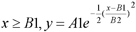
- A1 and B1 are an ordinate and an abscissa of a peak point of the envelope curve respectively, A2 is an ordinate of an intersection point of the envelope curve and the y-axis, B2 is a difference between an abscissa of a point that is located to the left of the peak point and is half the height of the peak point on the envelope curve (that can be called the left half height point) and the abscissa of the peak point, and B3 is a difference between an abscissa of a point that is located to the right of the peak point and is half the height of the peak point on the envelope curve (that can be called the right half height point) and the abscissa of the peak point.
- Then, after parameters of the envelope curve are obtained, the diastolic blood pressure (DBP), the systolic blood pressure (SBP), and the mean blood pressure (MBP) are computed as per the following formula:


- The blood pressure can be computed not only by the above-mentioned double Gaussian fitting, but also selectively by envelope bathmometry.
- Specifically, the principle of the envelope bathmometry is that: an artery has highest elasticity under zero transmural pressure conditions, and two inflection points are located to the left and to the right of the peak point of the envelope curve of the pressure pulse wave. Cuff pressures corresponding to the two inflection points are the systolic blood pressure (SBP) and the diastolic blood pressure (DBP), respectively. The inflection points correspond to largest pressure changes, so that an absolute value of a first derivative of the corresponding envelope curve is a maximum value. In this case, a value of a second derivative of the corresponding envelope curve should be 0. Therefore, the two inflection points to the left and to the right of the peak point of the envelope curve can be found by computing the value of the first derivative or the value of the second derivative of the envelope curve of the pressure pulse wave, thereby computing the systolic blood pressure (SBP) and the diastolic blood pressure (DBP) respectively.
-
FIG. 7 and FIG. 8 are a schematic diagram of a blood pressure detection result detected at a third knuckle of a finger via an apparatus for detecting biometric information provided in an embodiment of the present disclosure and a schematic diagram of a blood pressure detection result detected at a second knuckle of a finger via an apparatus for detecting biometric information provided in an embodiment of the present disclosure, respectively. - In
FIG. 7 and FIG. 8 , the abscissas represent different tested objects, while the ordinates represent sizes of blood pressure values (mmHg). - The SBP0 and DBP0 represent real values of the systolic blood pressure and the diastolic blood pressure recorded using a mercury stethoscope, while SBP1 and DBP1 represent values of the systolic blood pressure and the diastolic blood pressure computed by collecting a pressure pulse wave at a fingertip.
- As can be seen from
FIG. 7 and FIG. 8 , the blood pressure detection results at the third knuckle and the second knuckle are very close to the blood pressure detection results recorded using a mercury stethoscope. Therefore, it is feasible to perform blood pressure detection at the third knuckle and the second knuckle. - In Table 1 below, blood pressure measurement is performed on 25 subjects at different sites such as the arm, wrist, third knuckle, and second knuckle by collecting pressure pulse waves via oscillography, by envelope fitting via extraction of peaks of the pressure pulse waves, and finally by computing a correlation coefficient among the envelope peak (EP) and the systolic blood pressure (SBP), the diastolic blood pressure (DBP), and the mean arterial pressure (MAP).
Table 1 Position Normal blood pressure (15 people) Hypertension (10 people) SBP vs. EP DBP vs. EP MAP vs. EP SBP vs. EP DBP vs. EP MAP vs. EP Arm 0.9682 0.9845 0.9799 0.9492 0.8307 0.9161 Wrist 0.8655 0.9550 0.9625 0.7405 0.7444 0.7627 Third knuckle 0.8332 0.9013 0.8975 0.6945 0.8776 0.7203 Second knuckle 0.8181 0.8006 0.8338 0.6922 0.8924 0.8226 - As can be seen from Table 1, the correlation coefficient among the systolic blood pressure (SBP), the diastolic blood pressure (DBP), and the mean arterial pressure (MAP) measured at the arm, wrist, third knuckle, and second knuckle and the envelope peak EP is strongly correlated with blood pressures at the third knuckle and the second knuckle, no matter for subjects with normal blood pressure or for subjects with hypertension.
- The accuracy evaluation results of the blood pressure data measured at the third knuckle and the second knuckle are presented in Table 2 below, respectively.
Table 2 Test site ISO standard (SD<8, MD<5) SBP_MD SBP_SD DBP_MD DBP_SD Third knuckle -4.44 5.67 -3.89 4.16 Second knuckle 4.17 7.73 1.53 4.64 - The MD represents a median deviation (MD), and SD represents a standard deviation (SD).
- The accuracy evaluation results of the blood pressure data measured at the third knuckle and the second knuckle can be seen from Table 2. Specifically, an absolute value of a median deviation (SBP_MD) of the systolic blood pressure (SBP) and an absolute value of a median deviation (DBP_MD) of the diastolic blood pressure (DBP) are each less than 5, and an absolute value of a standard deviation (SBP_SD) of the systolic blood pressure (SBP) and an absolute value of a standard deviation (DBP_SD) of the diastolic blood pressure (DBP) are each less than 8, complying with the ISO medical standard.
- The
apparatus 20 for detecting biometric information provided in the embodiments of the present disclosure measures blood pressure at the third knuckle and the second knuckle, and the accuracy of the obtained blood pressure data is up to standard. -
FIG. 9 is a structural block diagram of an electronic device provided in an embodiment of the present disclosure. - As shown in
FIG. 9 , the embodiment of the present disclosure further provides anelectronic device 40. Theelectronic device 40 includes theapparatus 20 for detecting biometric information provided in the above embodiments of the present disclosure and adisplay screen 30, where thedisplay screen 30 is arranged on an outer surface of theapparatus 20, and thedisplay screen 30 is configured to display the biometric information. - Specifically, the biometric information displayed on the
display screen 30 includes a blood pressure value, a blood oxygen value, and a heart rate value. Thedisplay screen 30 can display the blood pressure value separately, or can display the blood pressure value, the blood oxygen value, and the heart rate value simultaneously. - Optionally, the wearable device further includes a portable blood pressure measuring device, such as a smart ring, a finger clip-type blood pressure meter, a finger clip-type blood pressure oximeter, and a finger clip-type multi-parameter meter.
-
FIG. 10 is a schematic diagram of an electronic device provided in an embodiment of the present disclosure. - As shown in
FIG. 10 , theelectronic device 40 is a multifunctional finger clip-type blood pressure oximeter, which can measure the biometric information, such as a heart rate value, a blood oxygen value, a heart rate variability (HRV), and a blood pressure value. - The
electronic device 40 in the embodiments of the present disclosure can facilitate quickly and conveniently monitoring real-time blood pressure of hypertension users in a non-household environment, and improve the user experience. - The preferred embodiments of the present disclosure are described in detail above with reference to the drawings. However, the present disclosure is not limited to the specific details of the above-mentioned embodiments. Within the scope of the technical concept of the present disclosure, multiple simple modifications can be made to the technical solutions of the present disclosure, and the simple modifications are all encompassed within the scope of protection of the present disclosure.
Claims (12)
- An apparatus for detecting biometric information, comprising:a finger stall comprising a mechanical structure or a gasbag, wherein the mechanical structure or the gasbag is configured to fix the finger stall on a finger of a user;a pulse wave sensor comprising a light emitter and a photodiode, wherein the light emitter is configured to emit a light signal which reaches the photodiode after being reflected or transmitted by a to-be-detected object, and the photodiode is configured to convert the received light signal into an electrical signal;an analog front end electrically connected to the pulse wave sensor and configured to receive the electrical signal and output an analog front end signal; anda microcontroller unit electrically connected to the analog front end and configured to receive the analog front end signal and output the biometric information, the biometric information comprising a blood pressure value.
- The apparatus according to claim 1, wherein the apparatus further comprises a pressure detector electrically connected to the analog front end.
- The apparatus according to claim 1 or 2, wherein the finger stall is a two-end through type finger stall with an annular cross section.
- The apparatus according to claim 1 or 2, wherein the finger stall is a non-through type;the non-through type finger stall is only provided with an opening at one end; anda cross section of the non-through type finger stall is one of rectangle, circle, ellipse, and polygon, and the non-through type finger stall has an internal space for accommodating the finger of the user.
- The apparatus according to claim 3, wherein the finger stall further comprises an air conduit connected to the gasbag.
- The apparatus according to claim 4, wherein the mechanical structure comprises a spring structure, wherein the spring structure comprises a spring body and a connecting plate; and
the connecting plate is connected to one end of the spring body, another end of the spring body is connected to the finger stall, and the spring structure is arranged on one side inside the finger stall close to the opening. - The apparatus according to claim 6, wherein the spring body comprises a first spring body and a second spring body, and the connecting plate comprises a first connecting plate and a second connecting plate; and
the first connecting plate is connected to the first spring body, the second connecting plate is connected to the second spring body, the light emitter is arranged on the first connecting plate, and the photodiode is arranged on the second connecting plate. - The apparatus according to claim 4, wherein the mechanical structure or the gasbag is arranged on one side inside the finger stall close to the opening.
- The apparatus according to claim 4, wherein the mechanical structure comprises a motor structure, wherein the motor structure comprises a motor and a connecting plate, the connecting plate is connected to the motor, the motor is configured to control movement of the connecting plate, and the motor structure is arranged on one side inside the finger stall close to the opening.
- The apparatus according to claim 1, wherein the biometric information further comprises at least one of a heart rate value and a blood oxygen value.
- An electronic device, comprising the apparatus according to any one of claims 1 to 10 and a display screen arranged on an outer surface of the apparatus, wherein the display screen is configured to display the biometric information.
- The electronic device according to claim 11, comprising a smart ring, a finger clip-type blood pressure meter, a finger clip-type blood pressure oximeter, and a finger clip-type multi-parameter meter.
Applications Claiming Priority (1)
| Application Number | Priority Date | Filing Date | Title |
|---|---|---|---|
| PCT/CN2023/102523 WO2025000204A1 (en) | 2023-06-26 | 2023-06-26 | Biometric information measurement apparatus and electronic device |
Publications (2)
| Publication Number | Publication Date |
|---|---|
| EP4512316A1 true EP4512316A1 (en) | 2025-02-26 |
| EP4512316A4 EP4512316A4 (en) | 2026-03-04 |
Family
ID=93928069
Family Applications (1)
| Application Number | Title | Priority Date | Filing Date |
|---|---|---|---|
| EP23822225.1A Pending EP4512316A4 (en) | 2023-06-26 | 2023-06-26 | DEVICE FOR MEASURING BIOMETRIC INFORMATION AND ELECTRONIC DEVICE |
Country Status (3)
| Country | Link |
|---|---|
| US (1) | US20240423488A1 (en) |
| EP (1) | EP4512316A4 (en) |
| WO (1) | WO2025000204A1 (en) |
Family Cites Families (24)
| Publication number | Priority date | Publication date | Assignee | Title |
|---|---|---|---|---|
| JPH0751123B2 (en) * | 1987-06-25 | 1995-06-05 | オムロン株式会社 | Electronic blood pressure monitor for fingers |
| IL135077A0 (en) * | 2000-03-15 | 2001-05-20 | Orsense Ltd | A probe for use in non-invasive measurements of blood related parameters |
| AU2004203059A1 (en) * | 2004-06-08 | 2005-12-22 | The Government Of The United States Of America As Represented By The Secretary Of The Department Of Health And Human Services, Centers For Disease Control And Prevention | Apparatus and method for assessing peripheral circulation to evaluate a physiological condition |
| KR100660349B1 (en) * | 2005-01-07 | 2006-12-21 | 메디게이트(주) | Mobile blood pressure monitoring device using optical blood flow measurement signal |
| DE102005054152A1 (en) * | 2005-11-14 | 2007-05-16 | Viasys Healthcare Gmbh | Pulse sensor, pulse meter, oximeter, joystick and helmet |
| EP1978864A2 (en) * | 2006-01-30 | 2008-10-15 | Cardiosense, Ltd. | Apparatus, system and method for determining cardio-respiratory state |
| KR20090052442A (en) * | 2007-11-21 | 2009-05-26 | 엘지전자 주식회사 | Non-invasive blood pressure measuring method and apparatus |
| WO2011097399A1 (en) * | 2010-02-03 | 2011-08-11 | Nellcor Puritan Bennett Llc | Combined physiological sensor systems and methods |
| US10893837B2 (en) * | 2013-02-22 | 2021-01-19 | Cloud Dx, Inc. | Simultaneous multi-parameter physiological monitoring device with local and remote analytical capability |
| US10694958B2 (en) * | 2015-01-08 | 2020-06-30 | Cnsystems Medizintechnik Ag | Wearable hemodynamic sensor |
| CN107773223A (en) * | 2016-08-24 | 2018-03-09 | 上海佑壳尔科技有限公司 | A kind of online finger instrument for obtaining pulse wave and acquisition pulse wave peak shape parameter method |
| US10874307B2 (en) * | 2017-01-24 | 2020-12-29 | Verily Life Sciences Llc | Digital artery blood pressure monitor |
| US11382522B2 (en) * | 2017-09-29 | 2022-07-12 | Fitbit, Inc. | Position detection of blood pressure device |
| US20190150839A1 (en) * | 2017-11-17 | 2019-05-23 | Analog Devices, Inc. | Material characteristic signal detection method and apparatus |
| US11576583B2 (en) * | 2018-03-27 | 2023-02-14 | Samsung Electronics Co., Ltd. | Noninvasive blood pressure measurement method and device |
| US11089966B2 (en) * | 2018-05-07 | 2021-08-17 | The Chinese University Of Hong Kong | Devices and methods for non-invasive capillary blood pressure measurement |
| CN210138143U (en) * | 2019-05-06 | 2020-03-13 | 南京唐潮科技有限公司 | Finger-clamping type multi-parameter detector |
| TWI829953B (en) * | 2019-07-29 | 2024-01-21 | 美商心環科技股份有限公司 | Bioinformation measuring device |
| CN111839530A (en) * | 2020-06-15 | 2020-10-30 | 惠州市源医科技有限公司 | Finger clip oximeter capable of accurately measuring |
| CN111603173B (en) * | 2020-06-18 | 2021-02-05 | 深圳市美韵声科技有限公司 | Finger clamping mechanism of intelligent oximeter |
| CN214208328U (en) * | 2020-12-04 | 2021-09-17 | 福州数据技术研究院有限公司 | Integrated fingertip pulse diagnosis instrument and system |
| CN215503017U (en) * | 2020-12-25 | 2022-01-14 | 深圳市麦瑞康科技有限公司 | Finger clip oximeter |
| CN113786193B (en) * | 2021-09-22 | 2023-06-16 | 惠州安博臣科技有限公司 | Oximeter with protective structure |
| CN114983364B (en) * | 2022-05-26 | 2023-09-15 | 杭州兆观传感科技有限公司 | A blood pressure detection device based on arteriolar photoplethysm pulse wave |
-
2023
- 2023-06-26 EP EP23822225.1A patent/EP4512316A4/en active Pending
- 2023-06-26 WO PCT/CN2023/102523 patent/WO2025000204A1/en not_active Ceased
- 2023-12-15 US US18/541,084 patent/US20240423488A1/en active Pending
Also Published As
| Publication number | Publication date |
|---|---|
| US20240423488A1 (en) | 2024-12-26 |
| EP4512316A4 (en) | 2026-03-04 |
| WO2025000204A1 (en) | 2025-01-02 |
Similar Documents
| Publication | Publication Date | Title |
|---|---|---|
| US8574161B2 (en) | Vital sign monitor for cufflessly measuring blood pressure using a pulse transit time corrected for vascular index | |
| US11576583B2 (en) | Noninvasive blood pressure measurement method and device | |
| US7179228B2 (en) | Cuffless system for measuring blood pressure | |
| CN101810475B (en) | Electronic auscultation sphygmomanometer based on combination of Korotkoff sound method and oscillometric method | |
| CN101327121B (en) | Physiological parameter measuring device | |
| US9131859B2 (en) | Blood pressure measurement apparatus, recording medium that records blood pressure derivation program, and blood pressure derivation method | |
| US11006885B2 (en) | Apparatus for determining blood pressure | |
| US20060264771A1 (en) | Apparatus for evaluating cardiovascular functions | |
| US7270636B2 (en) | Apparatus and method for pulse detection | |
| CN105943005A (en) | Non-invasive blood pressure detection method based on mixing of photoelectric green-light pulses and electrocardiogram | |
| CN105708431A (en) | Real-time blood pressure measuring device and measuring method | |
| CN101229058A (en) | Initial calibration device for measuring arterial blood pressure by pulse wave transmission time method | |
| CN112890790B (en) | Wearable noninvasive dynamic blood pressure tracking and monitoring method | |
| CN116636821B (en) | Blood pressure management system and method | |
| US20120108985A1 (en) | Cuffless blood pressure monitor | |
| CN220512844U (en) | Biological characteristic information detection device and electronic equipment | |
| CN1552282A (en) | Blood pressure measuring method and device based on heart sound signals | |
| CN116746894A (en) | Biometric information detection device and electronic equipment | |
| US20240423488A1 (en) | Apparatus for detecting biometric information and electronic device | |
| TWI644628B (en) | Physiological sensing fabric and method thereof | |
| Jin-ling et al. | Design of electronic blood pressure monitoring system based on mobile telemedicine system | |
| US11412942B2 (en) | Apparatus, system and method for obtaining hemodynamic data of an individual | |
| TW201740878A (en) | Physiological detection method and device thereof | |
| Shyu et al. | Development of a cuffless blood pressure measurement system | |
| US12268481B2 (en) | Photoplethysmography-based blood pressure monitoring device |
Legal Events
| Date | Code | Title | Description |
|---|---|---|---|
| STAA | Information on the status of an ep patent application or granted ep patent |
Free format text: STATUS: UNKNOWN |
|
| STAA | Information on the status of an ep patent application or granted ep patent |
Free format text: STATUS: THE INTERNATIONAL PUBLICATION HAS BEEN MADE |
|
| PUAI | Public reference made under article 153(3) epc to a published international application that has entered the european phase |
Free format text: ORIGINAL CODE: 0009012 |
|
| STAA | Information on the status of an ep patent application or granted ep patent |
Free format text: STATUS: REQUEST FOR EXAMINATION WAS MADE |
|
| 17P | Request for examination filed |
Effective date: 20231222 |
|
| AK | Designated contracting states |
Kind code of ref document: A1 Designated state(s): AL AT BE BG CH CY CZ DE DK EE ES FI FR GB GR HR HU IE IS IT LI LT LU LV MC ME MK MT NL NO PL PT RO RS SE SI SK SM TR |
|
| REG | Reference to a national code |
Ref country code: DE Ref legal event code: R079 Free format text: PREVIOUS MAIN CLASS: A61B0005021000 Ipc: A61B0005000000 |
|
| A4 | Supplementary search report drawn up and despatched |
Effective date: 20260204 |
|
| RIC1 | Information provided on ipc code assigned before grant |
Ipc: A61B 5/00 20060101AFI20260129BHEP Ipc: A61B 5/021 20060101ALI20260129BHEP Ipc: A61B 5/022 20060101ALI20260129BHEP Ipc: A61B 5/024 20060101ALI20260129BHEP Ipc: A61B 5/1455 20060101ALI20260129BHEP |