EP4512263A1 - Aerosol generating device and heating module - Google Patents
Aerosol generating device and heating module Download PDFInfo
- Publication number
- EP4512263A1 EP4512263A1 EP23811064.7A EP23811064A EP4512263A1 EP 4512263 A1 EP4512263 A1 EP 4512263A1 EP 23811064 A EP23811064 A EP 23811064A EP 4512263 A1 EP4512263 A1 EP 4512263A1
- Authority
- EP
- European Patent Office
- Prior art keywords
- electrode
- heating member
- heating
- electrical conduction
- aerosol generating
- Prior art date
- Legal status (The legal status is an assumption and is not a legal conclusion. Google has not performed a legal analysis and makes no representation as to the accuracy of the status listed.)
- Pending
Links
Images




Classifications
-
- A—HUMAN NECESSITIES
- A24—TOBACCO; CIGARS; CIGARETTES; SIMULATED SMOKING DEVICES; SMOKERS' REQUISITES
- A24F—SMOKERS' REQUISITES; MATCH BOXES; SIMULATED SMOKING DEVICES
- A24F40/00—Electrically operated smoking devices; Component parts thereof; Manufacture thereof; Maintenance or testing thereof; Charging means specially adapted therefor
- A24F40/50—Control or monitoring
- A24F40/57—Temperature control
-
- A—HUMAN NECESSITIES
- A24—TOBACCO; CIGARS; CIGARETTES; SIMULATED SMOKING DEVICES; SMOKERS' REQUISITES
- A24F—SMOKERS' REQUISITES; MATCH BOXES; SIMULATED SMOKING DEVICES
- A24F40/00—Electrically operated smoking devices; Component parts thereof; Manufacture thereof; Maintenance or testing thereof; Charging means specially adapted therefor
- A24F40/40—Constructional details, e.g. connection of cartridges and battery parts
- A24F40/46—Shape or structure of electric heating means
-
- A—HUMAN NECESSITIES
- A24—TOBACCO; CIGARS; CIGARETTES; SIMULATED SMOKING DEVICES; SMOKERS' REQUISITES
- A24F—SMOKERS' REQUISITES; MATCH BOXES; SIMULATED SMOKING DEVICES
- A24F40/00—Electrically operated smoking devices; Component parts thereof; Manufacture thereof; Maintenance or testing thereof; Charging means specially adapted therefor
- A24F40/20—Devices using solid inhalable precursors
-
- A—HUMAN NECESSITIES
- A24—TOBACCO; CIGARS; CIGARETTES; SIMULATED SMOKING DEVICES; SMOKERS' REQUISITES
- A24F—SMOKERS' REQUISITES; MATCH BOXES; SIMULATED SMOKING DEVICES
- A24F40/00—Electrically operated smoking devices; Component parts thereof; Manufacture thereof; Maintenance or testing thereof; Charging means specially adapted therefor
- A24F40/50—Control or monitoring
Definitions
- Embodiments of this application relate to the field of aerosol generating technologies, and in particular, to an aerosol generating device and a heating module.
- An aerosol generating device is configured to heat an aerosol generating product, to generate an aerosol.
- the aerosol generating device includes a heating body configured to heat the aerosol generating product.
- the existing heating body usually generates heat in an entire section simultaneously in a non-diversified manner, which cannot meet a plurality of current heating requirements for the aerosol generating product.
- the switch control circuit can control the positive electrode output end and the negative electrode output end of the power supply assembly to be in electrical conduction with different electrodes, so that different electrodes can become a negative electrode and a positive electrode. Therefore, the first heating member and the second heating member have a plurality of switchable operation modes.
- the switch control circuit controls the second electrode to be in electrical conduction with the positive electrode output end, to allow the second electrode to become a positive electrode, and controls the first electrode and the third electrode to be in electrical conduction with the negative electrode output end separately or simultaneously, to allow at least one of the first electrode and the third electrode to become a negative electrode, so that the first heating member and the second heating member can perform heating separately or simultaneously in parallel.
- the switch control circuit controls the first electrode to be in electrical conduction with the positive electrode output end, to allow the first electrode to become a positive electrode, and controls the second electrode and the third electrode to be in electrical conduction with the negative electrode output end one after the other, to allow the second electrode and the third electrode to become negative electrodes one after the other, so that the first heating member may perform heating earlier than the second heating member, and a heating mode thereof may be: the first heating member performs heating alone, the first heating member and the second heating member perform heating simultaneously, or the like.
- first”, “second”, and “third” of this application are used for descriptive purposes only and should not be construed as indicating or implying relative importance or implicitly indicating the number or order of technical features indicated. All directional indications (for example, up, down, left, right, front, back) in the embodiments of this application are only used for explaining relative position relationships, movement situations or the like between the various components in a specific posture (as shown in the accompanying drawings). If the specific posture changes, the directional indications change accordingly.
- the terms “include”, “have”, and any variant thereof are intended to cover a non-exclusive inclusion.
- the aerosol generating device includes a receiving cavity 2 configured to receive the aerosol generating product 1 and a heating module 4 configured to heat the aerosol generating product 1, and further includes a power supply assembly 3, and the power supply assembly 3 is configured to supply power for operation of the heating module 4.
- the aerosol generating device has an insertion opening, and the aerosol generating product 1 is removably received in the receiving cavity 2 through the insertion opening.
- the heating module 4 has at least one part extending in a longitudinal direction in the receiving cavity 2, and generates heat through electromagnetic induction under a changing magnetic field, or generates heat through a resistor when being energized, or radiates infrared rays to the aerosol generating product 1 when being excited, to heat the aerosol generating product 1 (for example, a cigarette), and volatilize at least one component of the aerosol generating product 1 to form an aerosol for inhalation.
- the heating module 4 includes a heating assembly 41.
- the heating assembly 41 may release energy and heat the aerosol generating product 1 by using the released energy, to allow the aerosol generating product to generate an aerosol.
- the heating assembly 41 is made of a resistive conductive material including iron-chromium-aluminum alloy, nickel-chromium alloy, nickel-iron alloy, platinum, tungsten, silver, conductive ceramic, and the like, or made of a conductive material including at least one of the foregoing materials, and therefore can generate heat through a resistor when conducting electricity, to heat the aerosol generating product 1, to volatilize at least one component in the aerosol generating product 1 to form an aerosol.
- a resistive conductive material including iron-chromium-aluminum alloy, nickel-chromium alloy, nickel-iron alloy, platinum, tungsten, silver, conductive ceramic, and the like, or made of a conductive material including at least one of the foregoing materials, and therefore can generate heat through a resistor when conducting electricity, to heat the aerosol generating product 1, to volatilize at least one component in the aerosol generating product 1 to form an aerosol.
- the infrared electrothermal coating may be formed by infrared electric heating ink, ceramic powder, and an inorganic adhesive that are fully stirred, evenly coated on the outer surface of the base body 412, and then dried for solidification for a specified period of time.
- a thickness of the infrared electrothermal coating ranges from 30 ⁇ m to 50 ⁇ m.
- the infrared electrothermal coating may also be formed by tin(IV) chloride, tin(II) oxide, antimony(III) chloride, titanium(IV) chloride, and anhydrous copper(II) sulfate that are mixed in a specified proportion, stirred, and coated on the outer surface of the base body 412.
- the heating member 411 may be arranged on an outer surface of the tubular body.
- a preparation manner may be to arrange the heating member on the outer surface of the tubular body by plasma spraying or the like.
- the base body 412 may be made of a transparent material, for example, a quartz material, to increase a transmittance of infrared rays, so that the infrared rays can better radiate into the accommodating cavity 413.
- the infrared electrothermal coating may be arranged on the inner surface of the base body 412 to come into contact with the aerosol generating product 1, thereby reducing energy loss by shortening a distance between the aerosol generating product 1 and the infrared electrothermal coating.
- the heating assembly 41 further includes a conductive module, and the conductive module includes a first electrode 414 and a second electrode 415 that are arranged on the base body 412. Both the first electrode 414 and the electrode 415 are at least partially electrically connected to the infrared electrothermal coating 411, so that a current can flow from one electrode to the other electrode through the infrared electrothermal coating.
- Polarities of the first electrode 414 and the second electrode 415 are opposite, for example: the first electrode 414 is a positive electrode, and the second electrode 415 is a negative electrode; or the first electrode 414 is a negative electrode, and the second electrode 415 is a positive electrode.
- both the first electrode 414 and the second electrode 415 are in a ring shape (a closed ring shape) or a strip shape (a non-closed ring shape or a bar shape).
- the first electrode 414 and the second electrode 415 may be ring-shaped conductive coatings or strip-shaped conductive coatings coated on the outer surface of the base body 412 and close to two opposite ends of the base body, and the conductive coatings may be made of silver, gold, palladium, platinum, copper, nickel, molybdenum, tungsten, niobium, or an alloy material of the foregoing metal.
- the first electrode 414 and the second electrode 415 may alternatively be ring-shaped conductive sheets or arc-shaped conductive sheets sleeved on the outer surface of the base body 412 and close to two opposite ends of the base body, and the conductive sheets are conductive sheets made of a metal material, for example, copper sheets or steel sheets.
- the conductive module includes three electrodes, that is, a first electrode 414, a second electrode 415, and a third electrode 416.
- the first electrode 414 is electrically connected to the first heating member 4111
- the third electrode 416 is electrically connected to the second heating member 4112
- the first electrode 414 and the third electrode 415 are not in direct contact with each other and are spaced apart from each other
- the second electrode 415 is electrically connected to both the first heating member 4111 and the second heating member 4112
- the first heating member 4111 is electrically connected to the second heating member 4112 by the connection of the second electrode 415.
- the first electrode 414, the second electrode 415, and the third electrode 416 are arranged on the base body 412, and the first electrode 414 and the third electrode 416 are respectively arranged on two opposite sides of the second electrode 415.
- the first electrode 414, the second electrode 415, and the third electrode 416 are arranged on the base body 412, and all extend to a same end portion of the base body 412.
- the power supply assembly 3 includes a positive electrode output end and a negative electrode output end.
- the positive electrode output end is configured to output a positive current or voltage
- the negative electrode output end is configured to output a negative current or voltage.
- the aerosol generating device further includes a switch control circuit 5.
- the switch control circuit 5 may be arranged on the circuit board 31.
- the switch control circuit 5 is connected to the power supply assembly 3 and the electrodes, to allow one or more of the plurality of electrodes to be in electrical conduction with the positive electrode output end, thereby forming one or more positive electrodes, and allow one or more of the plurality of electrodes to be in electrical conduction with the negative electrode output end, thereby forming one or more negative electrodes.
- the second electrode 415 is a positive electrode configured to connect to a positive current or voltage, so that the second electrode 415 may form a common positive electrode of the first heating member 4111 and the second heating member 4112, and the first electrode 414 and the third electrode 416 are configured to connect to a negative current or voltage, and are both negative electrodes.
- the second electrode 415 is in electrical conduction with the positive electrode output end and the other two electrodes are in electrical conduction with the negative electrode output end.
- an equivalent circuit shown in FIG. 9 shows a circuit layout of the first heating member 4111, the second heating member 4112, the first electrode 414, the second electrode 415, and the third electrode 416.
- a voltage applied to the first heating member is greater than a voltage applied to the first heating member 4111 when the first heating member 4111 and the second heating member 4112 operate simultaneously (the first electrode 414 and the third electrode 416 are in electrical conduction through the first heating member 4111, the second electrode 415, and the second heating member 4112), so that when operation alone, the first heating member 4111 has a larger operation voltage because the voltage of the first heating member is not offloaded by the second heating member 4112, and then has larger heating efficiency. Therefore, the aerosol generating product 1 can quickly heat up, which helps reduce a waiting time for aerosol generating.
- the heating module 4 may be constructed into a tube shape, in which a cavity is provided.
- An upper end region of the cavity may be provided for the aerosol generating product 1 to be inserted, so as to accommodate the aerosol generating product 1, and the first heating member 4111 is arranged on a periphery of the aerosol generating product 1, so as to heat or perform heat preservation for the aerosol generating product 1.
- a lower end region of the cavity may be provided for the air heater 6 to be mounted, to accommodate the air heater 6.
- the air heater 6 may be in a porous structure made of a high heat conducting material, such as a honeycomb structure made of ceramic, graphite alloy, graphene, or the like, or the air heater 6 may be made of foamed metal, or the like.
- the heating members 411 are annular metal sheets, and the electrodes are also annular metal sheets.
- An electrode is electrically connected by nesting with a corresponding heating member 411, so as to jointly form a tube shape.
- the switch control circuit 5 automatically selects, according to an inhalation requirement, one of the electrodes to be in electrical conduction with the positive electrode output end of the power supply assembly 3 to become a positive electrode, and selects one or more of the remaining electrodes to be in electrical conduction with the negative electrode output end of the power supply assembly 3 to become one or more negative electrodes, so that an operation mode of the heating members can be selected, for example, a parallel relationship or a series relationship between the heating members can be determined.
- the second electrode 415 that is electrically connected to both the first heating member 4111 and the second heating member 4112 is selected as a positive electrode.
- the positive electrode may be switched by the switch control circuit 5, so that any electrode may become the positive electrode.
- the negative electrodes can be switched by the switch control circuit 5, so that different electrodes can form the negative electrodes and are in electrical conduction with the positive electrode.
- the switch control circuit 5 automatically selects, by using a preset program, a negative electrode that is preferentially in electrical conduction, or performs negative electrode switching.
- a negative electrode that is preferentially in electrical conduction
- the first electrode 414 is automatically selected to be in electrical conduction with the second electrode 415 when the heating module 4 just starts, so that the third electrode 416 is turned off or floated, thereby enabling the first heating member 4111 to operate alone under a relatively high voltage.
- the circuit board 31 automatically switches the second electrode 415 and the third electrode 416, so that the third electrode 416 is in electrical conduction with the first electrode 414, and the second electrode 415 is floated or turned off, thereby enabling the first heating member 4111 and the second heating member 4112 to operate simultaneously.
- the switch control circuit may be manually controlled by using a key or a control panel, so that the switch control circuit 5 selects a positive electrode and a negative electrode that is in electrical conduction with the positive electrode.
- the heating module 4 further includes a temperature detection element 42.
- the temperature detection element 42 is configured to detect a real-time temperature of the heating assembly 41 and transfer information about the detected temperature to a controller on the circuit board 31.
- the controller controls power input to the heating assembly 41 according to the real-time temperature, to prevent the temperature of the heating assembly 41 from being excessively high or low, ensure the yield of the aerosol and the taste, and reduce the generation of harmful substances.
- the temperature detection element 42 is in contact with the heating assembly 41, that is, collects the temperature of the heating assembly 41 through contact.
- the temperature detection element 42 may include an NTC (negative temperature coefficient) thermistor element, a PTC (positive temperature coefficient) thermistor element, or the like, and is not limited herein, as long as the temperature detection element can come into contact with the heating assembly 41 and can detect the temperature of the heating assembly 41 in real time.
- NTC negative temperature coefficient
- PTC positive temperature coefficient
- the temperature detection element 42 is in direct contact with the infrared electrothermal coating 411 in the heating assembly 41, to improve accuracy and real-time performance of temperature detection.
- the heating assembly 41 includes the foregoing base body 412, to prevent the temperature detection element 42 from occupying the accommodating cavity 413, thereby affecting the close fitting between the heating assembly 41 and the aerosol generating product 1, or affecting the insertion and removal of the aerosol generating product 1 relative to the accommodating cavity 413
- the infrared electrothermal coating 411 is preferentially arranged on the outer surface of the base body 412, and the temperature detection element 42 is in contact with the infrared electrothermal coating 411 on the outer side of the base body 412.
- the temperature detection element 42 is in surface contact with the heating assembly 41, to increase accuracy and sensitivity of temperature detection.
- the heat shrinkable tube may melt and foam at a high temperature, and after melting, adhere to the infrared electrothermal coating arranged on the heating assembly 42.
- the heating assembly 41 repeatedly generates heat and cools, the heat shrinkable tube cyclically expands and contracts, thereby tearing and destroying the infrared electrothermal coating 411.
- the heat shrinkable tube tears and destroys the infrared electrothermal coating 411 due to adhesion.
- a heat insulation layer 44 may be arranged between the heating assembly 42 and the fixing member 43.
- the heat insulation layer 44 may be made of one or more of aerogel, fiberglass felt, and heat insulation cotton.
- the heat insulation layer 44 can adapt to a shape of a surface of the heating assembly 42, and therefore can be better attached to the surface of the heating assembly 42.
- the heat insulation layer 44 is arranged on the surface of the heating assembly 42.
- An avoidance groove 441 is provided on the heat insulation layer 44.
- the temperature detection element 42 is arranged in the avoidance groove 441 and is in direct contact with the heating assembly 42 in the avoidance groove 441.
- a part of the temperature detection element 42 protrudes from the avoidance groove 441, so that the fixing member 43 can directly press the temperature detection element 42, the temperature detection element 42 is kept in contact with the heating assembly 41, and the temperature detection element 42 is limited in the avoidance groove 441, thereby ensuring that the temperature detection element 441 does not shake and is not displaced.
- the heat insulation layer 44 can absorb the thickness of the temperature detection element 42 through the avoidance groove 441, to reduce a height of a bulge at a position where the fixing member 43 comes into contact with the temperature detection element 42, which can effectively prevent local excessive tightening or stress concentration of the fixing member 43, and help balance forces in positions on the fixing member 43, thereby slowing the aging speed of the fixing member 43 and prolonging the service life of the fixing member 43.
- a lead of the temperature detection element 42 may be buried in the heat insulation layer 44, and preferably does not cause the outer surface of the heat insulation layer 44 to form a bulge.
- the heat insulation layer 44 covers the temperature detection element 42, and the temperature detection element 42 is arranged between the heat insulation layer 44 and the tubular body 41, so that the heat insulation layer 44 can have a relatively large thickness to absorb the thickness of the temperature detection element 42.
- an outer surface on the heat insulation layer 44 corresponding to the temperature detection element 42 and an outer surface adjacent to the temperature detection element have the same curvature, that is, the temperature detection element 42 does not cause the outer surface of the heat insulation layer 44 to form a bulge, thereby facilitating arrangement of the fixing member 43 on the outer side of the heat insulation layer 44, and effectively preventing the fixing member 43 from being unevenly stressed due to a local bulge.
- the heat insulation layer 44 is in a shape of a plurality of sheets or blocks arranged intermittently, or the heat insulation layer 44 is not formed into an annular strip shape.
- the heat insulation layer 44 mainly plays a role in separation, to prevent the fixing member 43 from coming into direct contact with the heating assembly 41.
- the fixing member 43 tightly hoops the heat insulation layer 44, so that the heat insulation layer 44 is fixed on the heating assembly 41.
- the heat insulation layer 44 is formed into a complete ring shape, and is arranged around the heating assembly 41 (in this case, the heating assembly 41 may be in a tubular shape, a sheet shape, or the like).
- the heat insulation layer 44 has a uniform thickness throughout. If the heating assembly 41 is tubular, regardless of the shape of the outer contour of the cross-section of the heating member, the outer contour of the cross-section of the heat insulation layer 44 may be preferably formed into a circle, so that the fixing member 43 can be assembled more smoothly.
- the fixing member is arranged around the heat insulation layer, to tightly hoop the heat insulation layer to fix the heat insulation layer on the heating assembly.
- the temperature detection element 42 may be displaced in the process, or the temperature detection element 42 also needs to be taken into account in the process to prevent the temperature detection element from being separated from the heating assembly 41.
- the temperature detection element 42 may be preliminarily fixed on the heating assembly 41 by using a high-temperature adhesive first.
- the temperature detection element 42 is preferably kept in direct contact with the heating assembly 41 by bundling or covering and adhering with a high-temperature adhesive tape.
- the reason for selecting the high-temperature adhesive includes: The high-temperature adhesive has balanced thermal coefficients, and does not contract after being cured, so that the infrared electrothermal coating 411 is not damaged by tearing the infrared electrothermal coating 411 on the surface of the heating assembly 41 during expansion and contraction.
- the heat insulation layer 44 may be preliminarily fixed on the heating assembly 41 by using a high-temperature adhesive first.
- the heat insulation layer 44 is preferably held on the heating assembly 41 by bundling or covering and adhering with a high-temperature adhesive tape.
- the high-temperature adhesive with balanced thermal coefficients and a low expansion and contraction rate is still used, so that a degree to which the heat shrinkable tube used as the fixing member 43 shrinks under heating is not affected, which can ensure maximum shrinkage of the heat shrinkable tube and squeeze the heat insulation layer 44 and the temperature detection element 42.
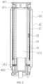
- the heating module 4 further includes a housing 45, a first holder 461, and a second holder 462.
- the first holder 461 is connected to an upper end of the heating assembly 41 and the housing 45, so that the upper end of the heating assembly 41 is positioned in the housing 45.
- the second holder 462 is connected to a lower end of the heating assembly 41 and the housing 45, so that the lower end of the heating assembly 42 is positioned in the housing 45.
- the first holder 461 and the second holder 462 may be made of a high-temperature-resistant plastic material, such as PEEK or PBI, which has low heat transfer efficiency, thereby effectively avoiding a case that the heat on the heating assembly 41 is transferred to the housing 45, resulting in heat loss and scalding of the housing 45.
- a high-temperature-resistant plastic material such as PEEK or PBI
- the first connecting member 471 connects the upper end of the heating assembly 41 and the first holder 461, so that the first holder 461 cannot be in direct contact with the heating assembly 41, thereby preventing the first holder 461 from being scorched by high temperature.
- the second connecting member 472 connects the lower end of the heating assembly 41 and the second holder 462, so that the second holder 462 cannot be in direct contact with the heating assembly 41, thereby preventing the second holder 462 from being scorched by high temperature. Therefore, the heating assembly 41 can adopt a larger heating power, which helps to shorten a waiting time for aerosol generating, can meet a requirement of the user for quick smoke emission, and can ensure a generation amount of aerosol per unit time, thereby facilitating improvement in the taste.
- the first holder 461 and the first connecting member 471 may be riveted together in an interference fit manner
- the second holder 462 and the second connecting member 472 may be riveted together in an interference fit manner.
- the reason why the upper end of the heating assembly 41 is held in the housing 45 in such a manner that the first holder 461 and the first connecting member 471 cooperate with each other includes: A complex structure may be arranged on the first holder 461 through a process such as injection molding, to simplify the first connecting member 471 as much as possible, so that the first connecting member 471 made of ceramic can be modularly mass-produced, which helps reduce production costs and improve production efficiency.
- the reason why the lower end of the heating assembly 41 is held in the housing in such a manner that the second holder 462 and the second connecting member 472 cooperate with each other also includes the foregoing reason.
- the housing 45 includes a heat preservation layer 451.
- the heat preservation layer 451 is arranged on a periphery of the heating assembly 41, and is configured to prevent heat from leaking and perform heat preservation for the heating assembly 41.
- the heat preservation layer 451 is a vacuum heat preservation layer, to improve the heat preservation effect.
- the switch control circuit controls the second electrode to be in electrical conduction with the positive electrode output end, to allow the second electrode to become a positive electrode, and controls the first electrode and the third electrode to be in electrical conduction with the negative electrode output end separately or simultaneously, to allow at least one of the first electrode and the third electrode to become a negative electrode, so that the first heating member 4111 and the second heating member 4112 can heat separately or simultaneously in parallel.
- the switch control circuit controls the first electrode to be in electrical conduction with the positive electrode output end, to allow the first electrode to become a positive electrode, and controls the second electrode and the third electrode to be in electrical conduction with the negative electrode output end one after the other, to allow the second electrode and the third electrode to become negative electrodes one after the other, so that the first heating member 4111 may perform heating earlier than the second heating member 4112, and a heating mode thereof may be: the first heating member 4111 performs heating alone, the first heating member 4111 and the second heating member 4112 perform heating simultaneously, or the like.
- the switch control circuit controls the third electrode to be in electrical conduction with the positive electrode output end, to allow the third electrode to become a positive electrode, and controls the second electrode and the first electrode to be in electrical conduction with the negative electrode output end one after the other, to allow the second electrode and the first electrode to become negative electrodes one after the other, so that the second heating member 4112 may perform heating earlier than the first heating member 4111, and a heating mode thereof may be: the second heating member 4112 performs heating alone, the second heating member 4112 and the first heating member 4111 perform heating simultaneously, or the like. Therefore, the aerosol generating device and the heating member 411 in the heating module 4 provided in this application have a plurality of operation modes and heating modes, so as to meet and adapt to a plurality of heating requirements.
Landscapes
- Resistance Heating (AREA)
Abstract
Description
- This application claims priority to
Chinese Patent Application No. 202210575878.2, filed with the China National Intellectual Property Administration on May 24, 2022 - Embodiments of this application relate to the field of aerosol generating technologies, and in particular, to an aerosol generating device and a heating module.
- An aerosol generating device is configured to heat an aerosol generating product, to generate an aerosol.
- The aerosol generating device includes a heating body configured to heat the aerosol generating product. However, during operation, the existing heating body usually generates heat in an entire section simultaneously in a non-diversified manner, which cannot meet a plurality of current heating requirements for the aerosol generating product.
- Embodiments of this application provide an aerosol generating device and a heating module. A plurality of heating members are arranged. Electrodes that are in electrical conduction with a positive electrode output end and a negative electrode output end of a power supply assembly are selected and controlled according to a switch control circuit, so that the heating members in the heating module can have a plurality of heating modes to meet different heating requirements.
- An embodiment of this application provides an aerosol generating device, including:
- a power supply assembly, including a positive electrode output end and a negative electrode output end;
- a heating module, the heating module including a plurality of heating members and a plurality of electrodes, the plurality of heating members including a first heating member and a second heating member, the plurality of electrodes including a first electrode, a second electrode and a third electrode, the first electrode being electrically connected to the first heating member, the second electrode being electrically connected to the first heating member and the second heating member, and the third electrode being electrically connected to the second heating member; and
- a switch control circuit, connected to the power supply assembly and the plurality of electrodes so as to selectively allow electrical conduction between one of the first electrode, the second electrode and the third electrode and the positive electrode output end, and allow electrical conduction between the other two of the first electrode, the second electrode and the third electrode and the negative electrode output end.
- An embodiment of this application provides a heating module, including a plurality of heating members and a plurality of electrodes;
- the plurality of heating members include a first heating member and a second heating member, both of which are configured to heat an aerosol generating product; and
- the plurality of electrodes include:
- a first electrode, electrically connected to the first heating member;
- a second electrode, electrically connected to the first heating member and the second heating member;
- a third electrode, electrically connected to the second heating member; and
- one of the first electrode, the second electrode, and the third electrode is a positive electrode, and the other two electrodes are both negative electrodes.
- In the aerosol generating device and the heating module described above, the switch control circuit can control the positive electrode output end and the negative electrode output end of the power supply assembly to be in electrical conduction with different electrodes, so that different electrodes can become a negative electrode and a positive electrode. Therefore, the first heating member and the second heating member have a plurality of switchable operation modes. For example, the switch control circuit controls the second electrode to be in electrical conduction with the positive electrode output end, to allow the second electrode to become a positive electrode, and controls the first electrode and the third electrode to be in electrical conduction with the negative electrode output end separately or simultaneously, to allow at least one of the first electrode and the third electrode to become a negative electrode, so that the first heating member and the second heating member can perform heating separately or simultaneously in parallel. In another example, the switch control circuit controls the first electrode to be in electrical conduction with the positive electrode output end, to allow the first electrode to become a positive electrode, and controls the second electrode and the third electrode to be in electrical conduction with the negative electrode output end one after the other, to allow the second electrode and the third electrode to become negative electrodes one after the other, so that the first heating member may perform heating earlier than the second heating member, and a heating mode thereof may be: the first heating member performs heating alone, the first heating member and the second heating member perform heating simultaneously, or the like. In still another example, the switch control circuit controls the third electrode to be in electrical conduction with the positive electrode output end, to allow the third electrode to become a positive electrode, and controls the second electrode and the first electrode to be in electrical conduction with the negative electrode output end one after the other, to allow the second electrode and the first electrode to become negative electrodes one after the other, so that the second heating member may perform heating earlier than the first heating member, and a heating mode thereof may be: the second heating member performs heating alone, the second heating member and the first heating member perform heating simultaneously, or the like. Therefore, the aerosol generating device and the heating member in the heating module provided in this application have a plurality of operation modes and heating modes, so as to meet and adapt to a plurality of heating requirements.
- One or more embodiments are exemplarily described with reference to the corresponding figures in the accompanying drawings, and the descriptions do not constitute a limitation to the embodiments. Components in the accompanying drawings that have same reference numerals are represented as similar components, and unless otherwise particularly stated, the figures in the accompanying drawings are not drawn to scale.
-
FIG. 1 is a schematic diagram of an aerosol generating device according to an embodiment of this application; -
FIG. 2 is a cross-sectional view of an aerosol generating device according to an embodiment of this application; -
FIG. 3 is a schematic exploded view of an aerosol generating device according to an embodiment of this application; -
FIG. 4 is a schematic exploded view of a heating module according to an embodiment of this application; -
FIG. 5 is another schematic exploded view of a heating module according to an embodiment of this application; -
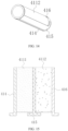
FIG. 6 is a cross-sectional view of a heating module according to another embodiment of this application; -
FIG. 7 is a schematic transverse-sectional view of a heating module according to another embodiment of this application; -
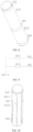
FIG. 8 is a schematic diagram of a heating assembly according to an embodiment of this application; -
FIG. 9 is a schematic diagram of electrodes and heating members on the heating assembly provided inFIG. 8 ; -
FIG. 10 is a schematic diagram of a heating assembly according to another embodiment of this application; -
FIG. 11 is a schematic diagram of unfolding electrodes and heating members of the heating assembly provided inFIG. 10 ; -
FIG. 12 is a schematic diagram of an equivalent circuit of electrodes and heating members on the heating assembly provided inFIG. 10 ; -
FIG. 13 is a schematic diagram of another equivalent circuit of electrodes and heating members on the heating assembly provided inFIG. 10 ; -
FIG. 14 is a schematic diagram of a heating assembly according to still another embodiment of this application; -
FIG. 15 is a schematic diagram of unfolding electrodes and heating members of the heating assembly provided inFIG. 14 ; -
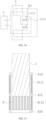
FIG. 16 is a schematic diagram of selecting an electrode by a switch control circuit according to an embodiment of this application; and -
FIG. 17 is a schematic transverse-sectional view of a heating module according to another embodiment of this application. - In the figures:
- 1. Aerosol generating product; 2. Receiving cavity; 3. Power supply assembly; 31. Circuit board; 32. Battery cell;
- 4. Heating module;
- 41. Heating assembly; 411. Heating member; 4111. First heating member; 4112. Second heating member; 412. Base body; 413. Accommodating cavity; 414. First electrode; 415. Second electrode; 416. Third electrode;
- 42. Temperature detection element; 43. Fixing member; 44. Heat insulation layer; 441. Avoidance groove; 45. Housing; 451. Heat preservation layer; 461. First holder; 462. Second holder; 471. First connecting member; 472. Second connecting member;
- 5. Switch control circuit; and 6. Air heater.
- The technical solutions in embodiments of this application are clearly and completely described in the following with reference to the accompanying drawings in the embodiments of this application. Apparently, the described embodiments are merely some rather than all of the embodiments of this application. All other embodiments obtained by a person of ordinary skill in the art based on the embodiments of this application without creative efforts shall fall within the protection scope of this application.
- The terms "first", "second", and "third" of this application are used for descriptive purposes only and should not be construed as indicating or implying relative importance or implicitly indicating the number or order of technical features indicated. All directional indications (for example, up, down, left, right, front, back) in the embodiments of this application are only used for explaining relative position relationships, movement situations or the like between the various components in a specific posture (as shown in the accompanying drawings). If the specific posture changes, the directional indications change accordingly. In addition, the terms "include", "have", and any variant thereof are intended to cover a non-exclusive inclusion. For example, a process, method, system, product, or device that includes a series of steps or units is not limited to the listed steps or units; and instead, further optionally includes a step or unit that is not listed, or further optionally includes another step or unit that is intrinsic to the process, method, product, or device.
- Embodiment mentioned in the specification means that particular features, structures, or characteristics described with reference to the embodiment may be included in at least one embodiment of this application. The term appearing at different positions of the specification may not refer to the same embodiment or an independent or alternative embodiment that is mutually exclusive with another embodiment. A person skilled in the art explicitly or implicitly understands that the embodiments described in the specification may be combined with other embodiments.
- It should be noted that, when a component is referred to as "being fixed to" another component, the component may be directly on the other component, or an intervening component may be present. When an element is considered as "being connected to" another element, the element may be directly connected to the another element, or one or more intermediate elements may exist between the element and the another element. The terms "vertical", "horizontal", "left", "right", and similar expressions used in this specification are only for purposes of illustration but not indicate a unique implementation.
- An embodiment of this application provides an aerosol generating device. The device may be configured to heat an aerosol generating product, so that the aerosol generating product is volatilized into an aerosol for inhalation. The aerosol may include Chinese herb, nicotine, or a flavor substance such as a tobacco spice. In this embodiment shown in
FIG. 1 , theaerosol generating product 1 is a tobacco product (such as a cigarette or cigar), but is not limited thereto. - In this embodiment shown in
FIG. 1 , the aerosol generating device includes a receivingcavity 2 configured to receive theaerosol generating product 1 and aheating module 4 configured to heat theaerosol generating product 1, and further includes apower supply assembly 3, and thepower supply assembly 3 is configured to supply power for operation of theheating module 4. - Referring to
FIG. 1 andFIG. 2 , the aerosol generating device has an insertion opening, and theaerosol generating product 1 is removably received in the receivingcavity 2 through the insertion opening. Theheating module 4 has at least one part extending in a longitudinal direction in the receivingcavity 2, and generates heat through electromagnetic induction under a changing magnetic field, or generates heat through a resistor when being energized, or radiates infrared rays to theaerosol generating product 1 when being excited, to heat the aerosol generating product 1 (for example, a cigarette), and volatilize at least one component of theaerosol generating product 1 to form an aerosol for inhalation. - The
power supply assembly 3 includes abattery cell 32 and acircuit board 31. Thebattery cell 32 is a rechargeable direct current battery cell that can output a direct current. Thecircuit board 31 is electrically connected to therechargeable battery cell 32 to control output of a current, a voltage, or an electric power of thebattery cell 32. In some embodiments, when a susceptor that can generate heat in a changing magnetic field is used as a heating member, thecircuit board 31 may change a direct current outputted by thebattery cell 32 into an alternating current, a changing magnetic field is generated under the alternating current by using a magnetic field generator (for example, an induction coil), and then theheating module 4 generates heat. In other embodiments, thebattery cell 32 may alternatively be a disposable battery that is not rechargeable or does not need to be charged. In other embodiments, thepower supply assembly 3 may be a wired power supply, and the wired power supply is directly connected to mains power through a plug to supply power to the aerosol generating device. - In an embodiment, a direct current supply voltage provided by the
battery cell 32 ranges from 2.5 V to 9.0 V, and a direct current that can be provided by thebattery cell 32 ranges from 2.5 A to 20 A. - Further, in an optional embodiment, the
aerosol generating product 1 is preferably made of a tobacco-containing material that releases a volatile compound from theaerosol generating product 1 when being heated; or may be made of a non-tobacco material suitable for electric heating and smoking. Theaerosol generating product 1 may be preferably made of a solid substrate, including one or more of powders, particles, fragmented strips, strips, or flakes of one or more of vanilla leaves, tobacco leaves, homogeneous tobacco, and expanded tobacco. Alternatively, theaerosol generating product 1 may include additional tobacco or non-tobacco volatile aroma compounds to be released when theaerosol generating product 1 is heated. In some optional embodiments, theaerosol generating product 1 is prepared in a shape of a conventional cigarette or cigar. - In the embodiments shown in
FIG. 1 andFIG. 2 , theheating module 4 includes aheating assembly 41. Theheating assembly 41 may release energy and heat theaerosol generating product 1 by using the released energy, to allow the aerosol generating product to generate an aerosol. - In an embodiment, the
heating assembly 41 includes a magnetic inductive material that can generate heat in a changing magnetic field, such as grade 430 stainless steel (SS430), grade 420 stainless steel (SS420), and an iron-nickel alloy material (such as permalloy), so that theheating assembly 41 can generate heat in the changing magnetic field, then generates heat spontaneously due to generation of eddy currents and magnetic hysteresis in the changing magnetic field, and conducts and/or radiates heat to theaerosol generating product 1, to heat theaerosol generating product 1. Correspondingly, the aerosol generating device further includes a magnetic field generator, such as an induction coil, configured to generate a changing magnetic field under an alternating current. Thecircuit board 31 is connected to thebattery cell 32 and the induction coil, and may convert a direct current outputted by thebattery cell 32 into an alternating current. Preferably, a frequency of the alternating current ranges from 80 KHz to 400 KHz. More specifically, the frequency may range from about 200 KHz to 300 KHz. - In an embodiment, the
heating assembly 41 is made of a resistive conductive material including iron-chromium-aluminum alloy, nickel-chromium alloy, nickel-iron alloy, platinum, tungsten, silver, conductive ceramic, and the like, or made of a conductive material including at least one of the foregoing materials, and therefore can generate heat through a resistor when conducting electricity, to heat theaerosol generating product 1, to volatilize at least one component in theaerosol generating product 1 to form an aerosol. - In an embodiment, the
heating assembly 41 is provided with aheating member 411. Theheating member 411 may be an infrared electrothermal coating, a resistive film, a flexible heating film (such as an FPC heating film), or the like. The infrared electrothermal coating can be excited by a current provided by thebattery cell 32 to radiate infrared rays to heat at least part of theaerosol generating product 1. When a wavelength of the infrared rays matches an absorption wavelength of theaerosol generating product 1, energy of the infrared rays is easily absorbed by theaerosol generating product 1. In an implementation of this application, the wavelength of the infrared rays is not limited and may be 0.75 µm to 1000 µm infrared rays, preferably 1.5 µm to 400 µm far infrared rays. - In an embodiment, the
heating assembly 41 further includes abase body 412. Thebase body 412 serves as a carrier of theheating member 411 and is configured to support theheating member 411. Referring toFIG. 5 , thebase body 412 is constructed into a tubular body, in which anaccommodating cavity 413 for accommodating theaerosol generating product 1 is provided, and theaerosol generating product 1 is heated in theaccommodating cavity 413 to generate an aerosol. Theheating member 411 may be arranged on an inner surface of the tubular body. A specific preparation manner may be to form theheating member 411 on the inner surface of the tubular body by electroplating. Alternatively, thebase body 412 is configured to be inserted into theaerosol generating product 1. - The infrared electrothermal coating may be formed by infrared electric heating ink, ceramic powder, and an inorganic adhesive that are fully stirred, evenly coated on the outer surface of the
base body 412, and then dried for solidification for a specified period of time. A thickness of the infrared electrothermal coating ranges from 30 µm to 50 µm. Certainly, the infrared electrothermal coating may also be formed by tin(IV) chloride, tin(II) oxide, antimony(III) chloride, titanium(IV) chloride, and anhydrous copper(II) sulfate that are mixed in a specified proportion, stirred, and coated on the outer surface of thebase body 412. Alternatively, the infrared electrothermal coating may be one of a silicon carbide ceramic layer, a carbon fiber composite layer, a titanium zirconium oxide ceramic layer, a titanium zirconium nitride ceramic layer, a titanium zirconium boride ceramic layer, a titanium zirconium carbide ceramic layer, a ferric oxide ceramic layer, a ferric nitride ceramic layer, a ferric boride ceramic layer, a ferric carbide layer, a rare earth oxide ceramic layer, a rare earth nitride ceramic layer, a rare earth boride ceramic layer, a rare earth carbide layer, a nickel cobalt oxide ceramic layer, a nickel cobalt nitride ceramic layer, a nickel cobalt boride ceramic layer, a nickel cobalt carbide layer, or a high silica molecular sieve ceramic layer. The infrared electrothermal coating may alternatively be a coating made of another existing material. - In another embodiment, as shown in
FIG. 5 , theheating member 411 may be arranged on an outer surface of the tubular body. A preparation manner may be to arrange the heating member on the outer surface of the tubular body by plasma spraying or the like. In this case, thebase body 412 may be made of a transparent material, for example, a quartz material, to increase a transmittance of infrared rays, so that the infrared rays can better radiate into theaccommodating cavity 413. - The
accommodating cavity 413 for accommodating theaerosol generating product 1 is provided inside thebase body 412. To protect theheating member 411 and prevent the heating member from being corroded and damaged by the aerosol, theheating member 411 may be arranged on the outer surface of thebase body 412, so as to isolate the infrared electrothermal coating from the aerosol. Alternatively, a protective layer may be arranged on the surface of the infrared electrothermal coating. The protective layer may be one or a combination of a polytetrafluroethylene layer and a glaze layer, or be made of another high temperature resistant material. The protective layer can isolate the infrared electrothermal coating from the aerosol and prevent wear of the infrared electrothermal coating. Therefore, the infrared electrothermal coating may be arranged on the inner surface of thebase body 412 to come into contact with theaerosol generating product 1, thereby reducing energy loss by shortening a distance between theaerosol generating product 1 and the infrared electrothermal coating. - In an embodiment, as shown in
FIG. 5 , a wall thickness of thebase body 412 is uniform, and on the base body, there are no obvious indentations and protrusions and there are no hollow holes and no blind grooves, to ensure that the heat is evenly distributed throughout thebase body 412, thereby ensuring uniform heating of theaerosol generating product 1. - In an embodiment, the
heating assembly 41 further includes a conductive module, and the conductive module includes afirst electrode 414 and asecond electrode 415 that are arranged on thebase body 412. Both thefirst electrode 414 and theelectrode 415 are at least partially electrically connected to the infraredelectrothermal coating 411, so that a current can flow from one electrode to the other electrode through the infrared electrothermal coating. Polarities of thefirst electrode 414 and thesecond electrode 415 are opposite, for example: thefirst electrode 414 is a positive electrode, and thesecond electrode 415 is a negative electrode; or thefirst electrode 414 is a negative electrode, and thesecond electrode 415 is a positive electrode. If theheating member 411 is arranged on the outer surface of thebase body 412, thefirst electrode 411 is arranged on the outer surface of thebase body 412 close to one end, and thesecond electrode 415 is arranged on the outer surface of the base body close to the other end. If theheating member 411 is arranged on the inner surface of thebase body 412, the conductive module may alternatively be arranged on the inner surface of thebase body 412, or span the inner surface and the outer surface of thebase body 412. - In an embodiment, both the
first electrode 414 and thesecond electrode 415 are in a ring shape (a closed ring shape) or a strip shape (a non-closed ring shape or a bar shape). Thefirst electrode 414 and thesecond electrode 415 may be ring-shaped conductive coatings or strip-shaped conductive coatings coated on the outer surface of thebase body 412 and close to two opposite ends of the base body, and the conductive coatings may be made of silver, gold, palladium, platinum, copper, nickel, molybdenum, tungsten, niobium, or an alloy material of the foregoing metal. Thefirst electrode 414 and thesecond electrode 415 may alternatively be ring-shaped conductive sheets or arc-shaped conductive sheets sleeved on the outer surface of thebase body 412 and close to two opposite ends of the base body, and the conductive sheets are conductive sheets made of a metal material, for example, copper sheets or steel sheets. - Referring to
FIG. 8 to FIG. 15 , there are twoheating members 411, that is, afirst heating member 4111 and asecond heating member 4112, and the conductive module includes three electrodes, that is, afirst electrode 414, asecond electrode 415, and athird electrode 416. Thefirst electrode 414 is electrically connected to thefirst heating member 4111, thethird electrode 416 is electrically connected to thesecond heating member 4112, thefirst electrode 414 and thethird electrode 415 are not in direct contact with each other and are spaced apart from each other, thesecond electrode 415 is electrically connected to both thefirst heating member 4111 and thesecond heating member 4112, and thefirst heating member 4111 is electrically connected to thesecond heating member 4112 by the connection of thesecond electrode 415. - Referring to
FIG. 8 , thefirst electrode 414, thesecond electrode 415, and thethird electrode 416 are arranged on thebase body 412, and thefirst electrode 414 and thethird electrode 416 are respectively arranged on two opposite sides of thesecond electrode 415. - Referring to
FIG. 10 , thefirst electrode 414, thesecond electrode 415, and thethird electrode 416 are arranged on thebase body 412, and all extend to a same end portion of thebase body 412. - In an embodiment, as shown in
FIG. 16 , thepower supply assembly 3 includes a positive electrode output end and a negative electrode output end. The positive electrode output end is configured to output a positive current or voltage, and the negative electrode output end is configured to output a negative current or voltage. The aerosol generating device further includes aswitch control circuit 5. Theswitch control circuit 5 may be arranged on thecircuit board 31. Theswitch control circuit 5 is connected to thepower supply assembly 3 and the electrodes, to allow one or more of the plurality of electrodes to be in electrical conduction with the positive electrode output end, thereby forming one or more positive electrodes, and allow one or more of the plurality of electrodes to be in electrical conduction with the negative electrode output end, thereby forming one or more negative electrodes. - In an embodiment, as shown in
FIG. 8 , thesecond electrode 415 is a positive electrode configured to connect to a positive current or voltage, so that thesecond electrode 415 may form a common positive electrode of thefirst heating member 4111 and thesecond heating member 4112, and thefirst electrode 414 and thethird electrode 416 are configured to connect to a negative current or voltage, and are both negative electrodes. This is a case that thesecond electrode 415 is in electrical conduction with the positive electrode output end and the other two electrodes are in electrical conduction with the negative electrode output end. In this case, an equivalent circuit shown inFIG. 9 shows a circuit layout of thefirst heating member 4111, thesecond heating member 4112, thefirst electrode 414, thesecond electrode 415, and thethird electrode 416. That is, thefirst heating member 4111 and thesecond heating member 4112 are connected in parallel, so that thefirst heating member 4111 and thesecond heating member 4112 may be switched to perform heating separately, or may be switched to perform heating simultaneously. Therefore, thefirst heating member 4111 and thesecond heating member 4112 may perform segmented heating on theaerosol generating product 1, or perform heating on theaerosol generating product 1 in different time segments, or perform heating on theaerosol generating product 1 in a same time segment. That is, either thefirst electrode 414 or thethird electrode 416 is in electrical conduction with the negative electrode output end, or the first electrode and the third electrode may be in electrical conduction with the negative electrode output end in different time segments. - In an embodiment, the
second electrode 415 is a common positive electrode of thefirst heating member 4111 and thesecond heating member 4112. Therefore, when thefirst heating member 4111 and thesecond heating member 4112 perform heating simultaneously, thefirst heating member 4111 and thesecond heating member 4112 may have a same operation voltage. Therefore, heating efficiency of thefirst heating member 4111 and thesecond heating member 4112 is related to operation resistances of thefirst heating member 4111 and thesecond heating member 4112. According to a heating requirement, thefirst heating member 4111 and thesecond heating member 4112 may be set to have different operation resistances. The operation resistances of thefirst heating member 4111 and thesecond heating member 4112 are not specifically limited in this embodiment. - In an embodiment, in an aerosol flowing direction, the
first heating member 4111 is located downstream of thesecond heating member 4112, thesecond heating member 4112 is configured to heat an upstream segment of theaerosol generating product 1, and thefirst heating member 4111 is configured to heat a relatively downstream segment of theaerosol generating product 1. In theaerosol generating product 1, air and/or the generated aerosol in the upstream segment of theaerosol generating product 1 has a high temperature under the action of thesecond heating member 4112, and flows into and heats the downstream segment of theaerosol generating product 1. In this case, heating efficiency of thefirst heating member 4111 may be less than heating efficiency of thesecond heating member 4112. Thefirst heating member 4111 is configured to replenish the temperature of the air that flows into the downstream segment and perform auxiliary heating on the downstream segment of theaerosol generating product 1, so that the downstream segment of theaerosol generating product 1 generates an aerosol. In addition, heating power of thefirst heating member 4111 may be reduced, to further reduce power consumption of the aerosol generating device. - In an embodiment, to meet the need for quick aerosol output, the
switch control circuit 5 of the aerosol generating device may be such arranged that thefirst heating member 4111 located downstream heats theaerosol generating product 1 in preference to thesecond heating member 4112, and aerosol generated in a downstream part of theaerosol generating product 1 may be preferably discharged, to shorten a distance by which the aerosol leaves theaerosol generating product 1, and avoid a case that the aerosol is cooled by anotheraerosol generating product 1 during flowing and condensed. Alternatively, when thefirst heating member 4111 generates heat alone, an input voltage or current is increased, so that thefirst heating member 4111 has higher heating power, to reduce an aerosol generating time. - In an embodiment, as shown in
FIG. 10 to FIG. 13 , in an aerosol flowing direction, thefirst heating member 4111 is located downstream of thesecond heating member 4112, thefirst electrode 414 electrically connected to thefirst heating member 4111 is a positive electrode, and thesecond electrode 415 and thethird electrode 416 are negative electrodes. This is a case that thefirst electrode 414 is in electrical conduction with the positive electrode output end and the other two electrodes are in electrical conduction with the negative electrode output end. Therefore, thefirst electrode 414 may form a common positive electrode of thefirst heating member 4111 and thesecond heating member 4112. Thethird electrode 416 and thesecond electrode 415 are configured to be in electrical conduction with a negative electrode output end of thepower supply assembly 3 in different time segments. That is, either thesecond electrode 415 or thethird electrode 416 is in electrical conduction with the negative electrode output end, or the first electrode and the third electrode may be in electrical conduction with the negative electrode output end in different time segments. - An equivalent circuit shown in
FIG. 12 shows a circuit layout of thefirst heating member 4111, thesecond heating member 4112, thefirst electrode 414, thesecond electrode 415, and thethird electrode 416. In this case, when thefirst electrode 414 is in electrical conduction with thethird electrode 416, thefirst heating member 4111 and thesecond heating member 4112 are connected in series, and operate simultaneously; and when thefirst electrode 414 is in electrical conduction with thesecond electrode 415, thefirst heating member 4111 operates, and thesecond heating member 4112 does not operate. Under the control of theswitch control circuit 5, a case that thefirst electrode 414 forms a common positive electrode of thefirst heating member 4111 and thesecond heating member 4112 and a total input voltage of theheating module 4 remains unchanged is used as an example. In a first case, if thefirst heating member 4111 operates alone (thefirst electrode 414 and thesecond electrode 415 are in electrical conduction through the first heating member 4111), a voltage applied to the first heating member is greater than a voltage applied to thefirst heating member 4111 when thefirst heating member 4111 and thesecond heating member 4112 operate simultaneously (thefirst electrode 414 and thethird electrode 416 are in electrical conduction through thefirst heating member 4111, thesecond electrode 415, and the second heating member 4112), so that when operation alone, thefirst heating member 4111 has a larger operation voltage because the voltage of the first heating member is not offloaded by thesecond heating member 4112, and then has larger heating efficiency. Therefore, theaerosol generating product 1 can quickly heat up, which helps reduce a waiting time for aerosol generating. In a second case, if thefirst heating member 4111 and thesecond heating member 4112 operate simultaneously, because thefirst heating member 4111 and thesecond heating member 4112 are connected in series, the voltage of thefirst heating member 4111 is offloaded by thesecond heating member 4112, so that a current flowing through thefirst heating member 4111 is reduced, and a current flowing through thesecond heating member 4112 is the same as or less than the current flowing through thefirst heating member 4111. Therefore, thefirst heating member 4111 and thesecond heating member 4112 can gently heat theaerosol generating product 1, to gradually release volatile substances evenly and fully. The first case and the second case may be arranged in different heating stages of theaerosol generating product 1 according to a heating requirement of the aerosol generating device. That is, theswitch control circuit 5 is configured to first control electrical conduction between thefirst electrode 414 and thesecond electrode 415, and then control electrical conduction between thefirst electrode 414 and thethird electrode 416, to allow thefirst heating member 4111 to generate heat earlier than thesecond heating member 4112. - Specifically, the
switch control circuit 5 starts theheating module 4 to operate, so that thefirst electrode 414 is in electrical conduction with thesecond electrode 415, and thefirst heating member 4111 operates preferentially, to meet the need for quick aerosol output. Then, thefirst electrode 414 is in electrical conduction with thethird electrode 416, the connection between thesecond electrode 415 and the negative electrode output end is interrupted or thesecond electrode 415 is floated, so that thefirst heating member 4111 and thesecond heating member 4112 operate together. It may be understood that the two negative electrodes are not in electrical conduction with the positive electrode simultaneously, to prevent thefirst heating member 4111 or thesecond heating member 4112 from being short-circuited. - As shown in
FIG. 10 to FIG. 13 , an extension length of thefirst heating member 4111 in the axial direction of theheating module 4 is less than an extension length of thesecond heating member 4112 in the axial direction of theheating module 4. On the premise that thefirst electrode 414 forms a common positive electrode of thefirst heating member 4111 and thesecond heating member 4112, thefirst heating member 4111 can quickly heat up theaerosol generating product 1 when operation alone, but inevitably heat theaerosol generating product 1 unevenly in the radial direction. Therefore, on the premise that the generated aerosol meets a puff, the axial length of thefirst heating member 4111 can be reduced, to reduce the waste of theaerosol generating product 1 on the periphery of the downstream segment of theaerosol generating product 1 corresponding to thefirst heating member 4111, and further help to save energy. That is, the length of thefirst heating member 4111 in the axial direction of theheating module 4 may be configured to be less than the length of thesecond heating member 4112 in the axial direction of theheating module 4. In another embodiment, when a direction of the current in thefirst heating member 4111 is the axial direction of theheating module 4, for example, axially upward or axially downward, a longer length of thefirst heating member 4111 in the axial direction of theheating module 4 indicates larger resistance of the first heating member. Therefore, under the same operation voltage, a shorter length of thefirst heating member 4111 in the axial direction of theheating module 4 indicates higher heating efficiency of the first heating member. Therefore, proper shortening of the length of thefirst heating member 4111 in the axial direction of theheating module 4 can increase heating efficiency of thefirst heating member 4111 when performing heating alone, thereby facilitating faster aerosol generating. - In another embodiment, the
first heating member 4111 is located downstream of thesecond heating member 4112 in an aerosol flowing direction; and thethird electrode 416 electrically connected to thesecond heating member 4112 is a positive electrode. Therefore, thethird electrode 416 may form a common positive electrode of thefirst heating member 4111 and thesecond heating member 4112. This is a case that thethird electrode 416 is in electrical conduction with the positive electrode output end and the other two electrodes are in electrical conduction with the negative electrode output end. Thefirst electrode 414 and thesecond electrode 415 are configured to be in electrical conduction with a negative electrode output end of thepower supply assembly 3 in different time segments. That is, either thefirst electrode 414 or thesecond electrode 415 is in electrical conduction with the negative electrode output end, or the first electrode and the third electrode may be in electrical conduction with the negative electrode output end in different time segments. - An equivalent circuit shown in
FIG. 13 shows a circuit layout of thefirst heating member 4111, thesecond heating member 4112, thefirst electrode 414, thesecond electrode 415, and thethird electrode 416. In this case, when thefirst electrode 414 is in electrical conduction with thethird electrode 416, the connection between thesecond electrode 415 and the negative electrode output end is interrupted or thesecond electrode 415 is floated, and thefirst heating member 4111 and thesecond heating member 4112 are connected in series, and operate simultaneously; and when thethird electrode 416 is in electrical conduction with thesecond electrode 415, the connection between thefirst electrode 414 and the negative electrode output end is interrupted or thefirst electrode 414 is floated, thesecond heating member 4112 operates, while thefirst heating member 4111 does not operate. - Under the control of the
switch control circuit 5, a case that thethird electrode 416 forms a common positive electrode of thefirst heating member 4111 and thesecond heating member 4112 and a total input voltage of theheating module 4 remains unchanged is used as an example. In a first case, if thesecond heating member 4112 operates alone (thethird electrode 416 and thesecond electrode 415 are in electrical conduction through the second heating member 4112), a voltage applied to the second heating member is greater than a voltage applied to thesecond heating member 4112 when thefirst heating member 4111 and thesecond heating member 4112 operate simultaneously (thefirst electrode 414 and thethird electrode 416 are in electrical conduction through thefirst heating member 4111, thesecond electrode 415, and the second heating member 4112), so that when operation alone, thesecond heating member 4112 has a larger operation voltage because the voltage of the second heating member is not offloaded by thefirst heating member 4111, and then has larger heating efficiency. In a second case, if thefirst heating member 4111 and thesecond heating member 4112 operate simultaneously, because thefirst heating member 4111 and thesecond heating member 4112 are connected in series, the voltage of thesecond heating member 4112 is offloaded by thefirst heating member 4111, so that a current flowing through thesecond heating member 4112 is reduced, and a current flowing through thefirst heating member 4111 is the same as or less than the current flowing through thesecond heating member 4112. Therefore, thefirst heating member 4111 and thesecond heating member 4112 can gently perform heating. The first case and the second case may be arranged in different heating stages of theaerosol generating product 1 according to a heating requirement of the aerosol generating device. That is, theswitch control circuit 5 is configured to first control electrical conduction between thethird electrode 416 and thesecond electrode 415, and then control electrical conduction between thefirst electrode 414 and thethird electrode 416, to allow thesecond heating member 4112 to generate heat earlier than thefirst heating member 4111. - In an embodiment, referring to
FIG. 17 , on the premise that thethird electrode 416 forms a common positive electrode of thefirst heating member 4111 and thesecond heating member 4112, the aerosol generating device further includes anair heater 6, where thefirst heating member 4111 is configured to heat or perform heat preservation for anaerosol generating product 1, and thesecond heating member 4112 is configured to heat theair heater 6. - The
heating module 4 may be constructed into a tube shape, in which a cavity is provided. An upper end region of the cavity may be provided for theaerosol generating product 1 to be inserted, so as to accommodate theaerosol generating product 1, and thefirst heating member 4111 is arranged on a periphery of theaerosol generating product 1, so as to heat or perform heat preservation for theaerosol generating product 1. A lower end region of the cavity may be provided for theair heater 6 to be mounted, to accommodate theair heater 6. Theair heater 6 may be in a porous structure made of a high heat conducting material, such as a honeycomb structure made of ceramic, graphite alloy, graphene, or the like, or theair heater 6 may be made of foamed metal, or the like. Any structure that can allow air to pass through and can heat up under the energy released by thesecond heating member 4112 to heat the flowing air may form theair heater 6 required in this embodiment. Thesecond heating member 4112 is arranged on a periphery of theair heater 6, and is configured to heat theair heater 6, then theair heater 6 heats air flowing into the air heater to form the air into hot air, and the hot air continues to flow to enter theaerosol generating product 1, to bake theaerosol generating product 1. - On the premise that the
third electrode 416 forms a common positive electrode of thefirst heating member 4111 and thesecond heating member 4112, thesecond heating member 4112 has a high heating power when performing heating alone, so that theair heater 6 can be quickly heated, and then hot air can be quickly formed. When thefirst heating member 4111 and thesecond heating member 4112 perform heating simultaneously, the heating power of both thefirst heating member 4111 and thesecond heating member 4112 is low, so that thefirst heating member 4111 can preheat and perform heat preservation for theaerosol generating product 1, and thesecond heating member 4112 can perform heat preservation for theair heater 6. Therefore, theswitch control circuit 5 switches the negative electrode in electrical conduction with thethird electrode 416 back and forth according to a preset frequency, or allows thethird electrode 416 to be in electrical conduction with thesecond electrode 415 and thefirst electrode 414 in turn according to a preset frequency, to heat theaerosol generating product 1 and theair heater 6, so that theaerosol generating product 1 can be fully baked to generate an aerosol, and energy consumption can be greatly reduced, thereby saving energy. - In an embodiment, as shown in
FIG. 14 and FIG. 15 , thefirst heating member 4111 and thesecond heating member 4112 separately extend in an axial direction of theheating module 4, and thefirst heating member 4111 and thesecond heating member 4112 are distributed in parallel in a circumferential direction of theheating module 4. In this case, the electrode connection between thefirst heating member 4111 and thesecond heating member 4112 may include the following three cases: Case (1): Thesecond electrode 415 connected to both thefirst heating member 4111 and thesecond heating member 4112 is a common positive electrode, and thefirst electrode 414 and thethird electrode 416 are negative electrodes. An equivalent circuit thereof is shown inFIG. 9 . Case (2): Thefirst electrode 414 is a positive electrode, and thesecond electrode 415 and thethird electrode 416 are negative electrodes. It may be understood that the two negative electrodes are not in electrical conduction with the positive electrode simultaneously, to prevent thefirst heating member 4111 or thesecond heating member 4112 from being short-circuited. Case (3): Thethird electrode 416 is a positive electrode, and thesecond electrode 415 and thefirst electrode 414 are negative electrodes. It may be understood that the two negative electrodes are not in electrical conduction with the positive electrode simultaneously, to prevent thefirst heating member 4111 or thesecond heating member 4112 from being short-circuited. That is, one of thefirst electrode 414, thesecond electrode 415, and thethird electrode 416 is in electrical conduction with the positive electrode output end, and the other two electrodes are in electrical conduction with the negative electrode output end. In other embodiments, there may be three ormore heating members 411. Correspondingly, the electrodes may include a fourth electrode, a fifth electrode, and the like. When there are more than twoheating members 411, the plurality ofheating members 411 may be preferably electrically connected in sequence, and twoadjacent heating members 411 may share one electrode. The positive electrode may form a common positive electrode of the plurality ofheating members 411, and the remainingheating members 411 are electrically connected to the negative electrodes. Therefore, different negative electrodes may be selected to be in electrical conduction with the positive electrode, so thatdifferent heating members 411 are connected in series and participate in heating operation. - In an embodiment, as shown in
FIG. 14 and FIG. 15 , thefirst heating member 4111 and thesecond heating member 4112 are arranged distributively on thebase body 412 in a circumferential direction of thebase body 412; and thefirst electrode 414, thesecond electrode 415, and thethird electrode 416 are arranged on thebase body 412, and thefirst electrode 414 and thethird electrode 416 are respectively arranged on two opposite sides of thesecond electrode 415. - In other embodiments, there may be three or
more heating members 411. Correspondingly, the electrodes may include a fourth electrode, a fifth electrode, and the like. Therefore, theheating module 4 may include a plurality of heating groups. Each heating group includes afirst heating member 4111 and asecond heating member 4112, and further includes afirst electrode 414, asecond electrode 415, and athird electrode 416. Thesecond electrode 415 is electrically connected to thefirst heating member 4111 and thesecond heating member 4112, thefirst electrode 414 is electrically connected to thefirst heating member 4111, thethird electrode 416 is electrically connected to thesecond heating member 4112, one of thefirst electrode 414, thesecond electrode 415, and thethird electrode 416 is a positive electrode, and the remaining two electrodes are negative electrodes. The plurality of heating groups are arranged at different positions on theheating module 4, so that the plurality of heating groups may generate heat cooperatively, for example, all the heating groups generate heat simultaneously at the same power (single-segment heating), or the plurality of heating groups generate heat at different times (segmented heating), or the plurality of heating groups generate heat simultaneously but at different powers, or the plurality of heating groups generate heat at different times selectively based on a condition preset by theswitch control circuit 5. - In other embodiments, the
heating members 411 are annular metal sheets, and the electrodes are also annular metal sheets. An electrode is electrically connected by nesting with acorresponding heating member 411, so as to jointly form a tube shape. - In other embodiments, through a preset program, the
switch control circuit 5 automatically selects, according to an inhalation requirement, one of the electrodes to be in electrical conduction with the positive electrode output end of thepower supply assembly 3 to become a positive electrode, and selects one or more of the remaining electrodes to be in electrical conduction with the negative electrode output end of thepower supply assembly 3 to become one or more negative electrodes, so that an operation mode of the heating members can be selected, for example, a parallel relationship or a series relationship between the heating members can be determined. For example, thesecond electrode 415 that is electrically connected to both thefirst heating member 4111 and thesecond heating member 4112 is selected as a positive electrode. When both thefirst electrode 414 that is electrically connected to thefirst heating member 4111 and thethird electrode 416 that is electrically connected to thesecond heating member 4112 are selected to be in electrical conduction with the negative electrode output end of thepower supply assembly 3, thefirst heating member 4111 and thesecond heating member 4112 are connected in parallel to each other, and may simultaneously generate heat. When one of thefirst electrode 414 that is electrically connected to thefirst heating member 4111 and thethird electrode 416 that is electrically connected to thesecond heating member 4112 is selected to be in electrical conduction with the negative electrode output end of thepower supply assembly 3, either of thefirst heating member 4111 and thesecond heating member 4112 may independently generate heat. In another example, when thefirst electrode 414 electrically connected to thefirst heating member 4111 is selected as a positive electrode, and thethird electrode 416 electrically connected to thesecond heating member 4112 is selected to be in electrical conduction with the negative electrode output end, thefirst heating member 4111 and thesecond heating member 4112 may be connected in series, and thefirst heating member 4111 and thesecond heating member 4112 simultaneously generate heat; and when thefirst electrode 414 electrically connected to thefirst heating member 4111 is selected as a positive electrode, and thesecond electrode 415 electrically connected to thesecond heating member 4112 is selected to be in electrical conduction with the negative electrode output end, thefirst heating member 4111 may generate heat alone, and thesecond heating member 4112 does not generate heat. - It may be understood that the positive electrode may be switched by the
switch control circuit 5, so that any electrode may become the positive electrode. The negative electrodes can be switched by theswitch control circuit 5, so that different electrodes can form the negative electrodes and are in electrical conduction with the positive electrode. - In other embodiments, when the positive electrode is determined, the
switch control circuit 5 automatically selects, by using a preset program, a negative electrode that is preferentially in electrical conduction, or performs negative electrode switching. For example, when thefirst electrode 414 is a positive electrode, thefirst electrode 414 is automatically selected to be in electrical conduction with thesecond electrode 415 when theheating module 4 just starts, so that thethird electrode 416 is turned off or floated, thereby enabling thefirst heating member 4111 to operate alone under a relatively high voltage. After 3S (not limited to this time), thecircuit board 31 automatically switches thesecond electrode 415 and thethird electrode 416, so that thethird electrode 416 is in electrical conduction with thefirst electrode 414, and thesecond electrode 415 is floated or turned off, thereby enabling thefirst heating member 4111 and thesecond heating member 4112 to operate simultaneously. - In other embodiments, the switch control circuit may be manually controlled by using a key or a control panel, so that the
switch control circuit 5 selects a positive electrode and a negative electrode that is in electrical conduction with the positive electrode. - In the embodiments shown in
FIG. 2 to FIG. 7 , theheating module 4 further includes atemperature detection element 42. Thetemperature detection element 42 is configured to detect a real-time temperature of theheating assembly 41 and transfer information about the detected temperature to a controller on thecircuit board 31. The controller controls power input to theheating assembly 41 according to the real-time temperature, to prevent the temperature of theheating assembly 41 from being excessively high or low, ensure the yield of the aerosol and the taste, and reduce the generation of harmful substances. - The
temperature detection element 42 is in contact with theheating assembly 41, that is, collects the temperature of theheating assembly 41 through contact. Thetemperature detection element 42 may include an NTC (negative temperature coefficient) thermistor element, a PTC (positive temperature coefficient) thermistor element, or the like, and is not limited herein, as long as the temperature detection element can come into contact with theheating assembly 41 and can detect the temperature of theheating assembly 41 in real time. Certainly, it is not excluded that in other embodiments, a non-contact temperature detection device is used to detect the temperature of theheating assembly 41 in real time. - As shown in
FIG. 5 to FIG. 7 , thetemperature detection element 42 is in direct contact with the infraredelectrothermal coating 411 in theheating assembly 41, to improve accuracy and real-time performance of temperature detection. When theheating assembly 41 includes the foregoingbase body 412, to prevent thetemperature detection element 42 from occupying theaccommodating cavity 413, thereby affecting the close fitting between theheating assembly 41 and theaerosol generating product 1, or affecting the insertion and removal of theaerosol generating product 1 relative to theaccommodating cavity 413, the infraredelectrothermal coating 411 is preferentially arranged on the outer surface of thebase body 412, and thetemperature detection element 42 is in contact with the infraredelectrothermal coating 411 on the outer side of thebase body 412. Optionally, thetemperature detection element 42 is in surface contact with theheating assembly 41, to increase accuracy and sensitivity of temperature detection. - As shown in
FIG. 3 to FIG. 7 , theheating module 4 further includes a fixingmember 43, and the fixingmember 43 is configured to keep thetemperature detection element 42 in contact with theheating assembly 41. - The fixing
member 43 may be a heat shrinkable tube that contracts to implement tight hooping after being heated. After the heat shrinkable tube contracts, the heat shrinkable tube does not return to an original state. In other words, once the heat shrinkable tube contracts, the heat shrinkable tube can always press thetemperature detection element 42 and theheating assembly 41 tightly. The heat shrinkable tube may be one of heat shrinkable tubes such as a PVC heat shrinkable tube, a PET heat shrinkable tube, a PTFE heat shrinkable tube, and a silicone heat shrinkable tube. A shrinkage ratio of the heat shrinkable tube may be 1.6:1 or 4:1. A shrinkage ratio of the heat shrinkable tube may alternatively be 1.8:1, 2.2:1, or 3.6:1. A shrinkage ratio of the heat shrinkable tube may alternatively be other ratios, which are not listed one by one herein. In other embodiments, the fixingmember 43 may alternatively be an object such as an adhesive tape or a structural member that can keep thetemperature detection element 42 in contact with theheating assembly 41 through bundling, clamping, or the like. - However, the heat shrinkable tube may melt and foam at a high temperature, and after melting, adhere to the infrared electrothermal coating arranged on the
heating assembly 42. As theheating assembly 41 repeatedly generates heat and cools, the heat shrinkable tube cyclically expands and contracts, thereby tearing and destroying the infraredelectrothermal coating 411. Alternatively, during rework and disassembly, the heat shrinkable tube tears and destroys the infraredelectrothermal coating 411 due to adhesion. However, the costs of a heat shrinkable tube that can withstand a high temperature are very high. Therefore, in an embodiment, aheat insulation layer 44 may be arranged between theheating assembly 42 and the fixingmember 43. Theheat insulation layer 44 not only can prevent the temperature of theheating assembly 42 from being dissipated outward, but also can protect the fixingmember 43, and prevent the fixing member from being damaged by the high temperature. In addition, the fixingmember 43 is not in direct contact with theheating assembly 42, thereby protecting the infraredelectrothermal coating 411 and preventing the infrared electrothermal coating from being damaged. Since theheat insulation layer 44 is arranged between theheater 41 and the fixingmember 43, the fixingmember 43 cannot be in direct contact with theheater 41, and theheat insulation layer 44 can isolate a large amount of heat dissipated by theheater 41 to the fixingmember 43. Therefore, a heat shrinkable tube with a low temperature resistance can become the fixingmember 43 described in this application, such as a PVC heat shrinkable tube or a PET heat shrinkable tube. In other words, a requirement for a material of the heat shrinkable tube can be reduced, and costs of the selected heat shrinkable tube can be reduced. - The
heat insulation layer 44 may be made of one or more of aerogel, fiberglass felt, and heat insulation cotton. Optionally, theheat insulation layer 44 can adapt to a shape of a surface of theheating assembly 42, and therefore can be better attached to the surface of theheating assembly 42. - In an embodiment, as shown in
FIG. 3 to FIG. 5 , theheat insulation layer 44 is arranged on the surface of theheating assembly 42. Anavoidance groove 441 is provided on theheat insulation layer 44. Thetemperature detection element 42 is arranged in theavoidance groove 441 and is in direct contact with theheating assembly 42 in theavoidance groove 441. In addition, a part of thetemperature detection element 42 protrudes from theavoidance groove 441, so that the fixingmember 43 can directly press thetemperature detection element 42, thetemperature detection element 42 is kept in contact with theheating assembly 41, and thetemperature detection element 42 is limited in theavoidance groove 441, thereby ensuring that thetemperature detection element 441 does not shake and is not displaced. - The
heat insulation layer 44 can absorb the thickness of thetemperature detection element 42 through theavoidance groove 441, to reduce a height of a bulge at a position where the fixingmember 43 comes into contact with thetemperature detection element 42, which can effectively prevent local excessive tightening or stress concentration of the fixingmember 43, and help balance forces in positions on the fixingmember 43, thereby slowing the aging speed of the fixingmember 43 and prolonging the service life of the fixingmember 43. In an optional embodiment, a lead of thetemperature detection element 42 may be buried in theheat insulation layer 44, and preferably does not cause the outer surface of theheat insulation layer 44 to form a bulge. - In an embodiment, as shown in
FIG. 6 and FIG. 7 , there is noavoidance groove 441 on theheat insulation layer 44, theheat insulation layer 44 covers thetemperature detection element 42, and thetemperature detection element 42 is arranged between theheat insulation layer 44 and thetubular body 41, so that theheat insulation layer 44 can have a relatively large thickness to absorb the thickness of thetemperature detection element 42. Preferably, an outer surface on theheat insulation layer 44 corresponding to thetemperature detection element 42 and an outer surface adjacent to the temperature detection element have the same curvature, that is, thetemperature detection element 42 does not cause the outer surface of theheat insulation layer 44 to form a bulge, thereby facilitating arrangement of the fixingmember 43 on the outer side of theheat insulation layer 44, and effectively preventing the fixingmember 43 from being unevenly stressed due to a local bulge. - In an embodiment, the
heat insulation layer 44 is in a shape of a plurality of sheets or blocks arranged intermittently, or theheat insulation layer 44 is not formed into an annular strip shape. Theheat insulation layer 44 mainly plays a role in separation, to prevent the fixingmember 43 from coming into direct contact with theheating assembly 41. In addition, the fixingmember 43 tightly hoops theheat insulation layer 44, so that theheat insulation layer 44 is fixed on theheating assembly 41. - In another embodiment, as shown in
FIG. 7 , theheat insulation layer 44 is formed into a complete ring shape, and is arranged around the heating assembly 41 (in this case, theheating assembly 41 may be in a tubular shape, a sheet shape, or the like). Preferably, theheat insulation layer 44 has a uniform thickness throughout. If theheating assembly 41 is tubular, regardless of the shape of the outer contour of the cross-section of the heating member, the outer contour of the cross-section of theheat insulation layer 44 may be preferably formed into a circle, so that the fixingmember 43 can be assembled more smoothly. The fixing member is arranged around the heat insulation layer, to tightly hoop the heat insulation layer to fix the heat insulation layer on the heating assembly. - Because a process is required to arrange the
heat insulation layer 44 on theheating assembly 41, thetemperature detection element 42 may be displaced in the process, or thetemperature detection element 42 also needs to be taken into account in the process to prevent the temperature detection element from being separated from theheating assembly 41. To resolve this problem, in a preferred embodiment, thetemperature detection element 42 may be preliminarily fixed on theheating assembly 41 by using a high-temperature adhesive first. Thetemperature detection element 42 is preferably kept in direct contact with theheating assembly 41 by bundling or covering and adhering with a high-temperature adhesive tape. The reason for selecting the high-temperature adhesive includes: The high-temperature adhesive has balanced thermal coefficients, and does not contract after being cured, so that the infraredelectrothermal coating 411 is not damaged by tearing the infraredelectrothermal coating 411 on the surface of theheating assembly 41 during expansion and contraction. - Similarly, a process is also required to arrange the fixing
member 43 on theheat insulation layer 44. To prevent theheat insulation layer 44 from being displaced in the process, in a preferred embodiment, theheat insulation layer 44 may be preliminarily fixed on theheating assembly 41 by using a high-temperature adhesive first. Theheat insulation layer 44 is preferably held on theheating assembly 41 by bundling or covering and adhering with a high-temperature adhesive tape. The high-temperature adhesive with balanced thermal coefficients and a low expansion and contraction rate is still used, so that a degree to which the heat shrinkable tube used as the fixingmember 43 shrinks under heating is not affected, which can ensure maximum shrinkage of the heat shrinkable tube and squeeze theheat insulation layer 44 and thetemperature detection element 42. - Referring to
FIG. 2 andFIG. 3 , theheating module 4 further includes ahousing 45, afirst holder 461, and asecond holder 462. Thefirst holder 461 is connected to an upper end of theheating assembly 41 and thehousing 45, so that the upper end of theheating assembly 41 is positioned in thehousing 45. Thesecond holder 462 is connected to a lower end of theheating assembly 41 and thehousing 45, so that the lower end of theheating assembly 42 is positioned in thehousing 45. Thefirst holder 461 and thesecond holder 462 may be made of a high-temperature-resistant plastic material, such as PEEK or PBI, which has low heat transfer efficiency, thereby effectively avoiding a case that the heat on theheating assembly 41 is transferred to thehousing 45, resulting in heat loss and scalding of thehousing 45. - However, when the temperature on the
heating assembly 41 exceeds a melting threshold of thefirst holder 461 and thesecond holder 462, for example, exceeds 300°C, thefirst holder 461 and thesecond holder 462 may be deformed, thereby affecting fixing of theheating assembly 41. To resolve this problem, in a preferred embodiment, as shown inFIG. 2 andFIG. 3 , theheating module 4 further includes a first connectingmember 471 and a second connectingmember 472. The first connectingmember 471 and the second connectingmember 472 may be made of ceramic that is more resistant to high temperature than thefirst holder 461 and thesecond holder 462. The first connectingmember 471 connects the upper end of theheating assembly 41 and thefirst holder 461, so that thefirst holder 461 cannot be in direct contact with theheating assembly 41, thereby preventing thefirst holder 461 from being scorched by high temperature. The second connectingmember 472 connects the lower end of theheating assembly 41 and thesecond holder 462, so that thesecond holder 462 cannot be in direct contact with theheating assembly 41, thereby preventing thesecond holder 462 from being scorched by high temperature. Therefore, theheating assembly 41 can adopt a larger heating power, which helps to shorten a waiting time for aerosol generating, can meet a requirement of the user for quick smoke emission, and can ensure a generation amount of aerosol per unit time, thereby facilitating improvement in the taste. - The
first holder 461 and the first connectingmember 471 may be riveted together in an interference fit manner, and thesecond holder 462 and the second connectingmember 472 may be riveted together in an interference fit manner. The reason why the upper end of theheating assembly 41 is held in thehousing 45 in such a manner that thefirst holder 461 and the first connectingmember 471 cooperate with each other includes: A complex structure may be arranged on thefirst holder 461 through a process such as injection molding, to simplify the first connectingmember 471 as much as possible, so that the first connectingmember 471 made of ceramic can be modularly mass-produced, which helps reduce production costs and improve production efficiency. Similarly, the reason why the lower end of theheating assembly 41 is held in the housing in such a manner that thesecond holder 462 and the second connectingmember 472 cooperate with each other also includes the foregoing reason. - In this embodiment shown in
FIG. 2 , thehousing 45 includes aheat preservation layer 451. Theheat preservation layer 451 is arranged on a periphery of theheating assembly 41, and is configured to prevent heat from leaking and perform heat preservation for theheating assembly 41. Preferably, theheat preservation layer 451 is a vacuum heat preservation layer, to improve the heat preservation effect. - In the aerosol generating device and the heating module described above, the switch control circuit can control the positive electrode output end and the negative electrode output end of the power supply assembly to be in electrical conduction with different electrodes, so that different electrodes can become a negative electrode and a positive electrode. Therefore, the
first heating member 4111 and thesecond heating member 4112 have a plurality of switchable operation modes. For example, the switch control circuit controls the second electrode to be in electrical conduction with the positive electrode output end, to allow the second electrode to become a positive electrode, and controls the first electrode and the third electrode to be in electrical conduction with the negative electrode output end separately or simultaneously, to allow at least one of the first electrode and the third electrode to become a negative electrode, so that thefirst heating member 4111 and thesecond heating member 4112 can heat separately or simultaneously in parallel. In another example, the switch control circuit controls the first electrode to be in electrical conduction with the positive electrode output end, to allow the first electrode to become a positive electrode, and controls the second electrode and the third electrode to be in electrical conduction with the negative electrode output end one after the other, to allow the second electrode and the third electrode to become negative electrodes one after the other, so that thefirst heating member 4111 may perform heating earlier than thesecond heating member 4112, and a heating mode thereof may be: thefirst heating member 4111 performs heating alone, thefirst heating member 4111 and thesecond heating member 4112 perform heating simultaneously, or the like. In still another example, the switch control circuit controls the third electrode to be in electrical conduction with the positive electrode output end, to allow the third electrode to become a positive electrode, and controls the second electrode and the first electrode to be in electrical conduction with the negative electrode output end one after the other, to allow the second electrode and the first electrode to become negative electrodes one after the other, so that thesecond heating member 4112 may perform heating earlier than thefirst heating member 4111, and a heating mode thereof may be: thesecond heating member 4112 performs heating alone, thesecond heating member 4112 and thefirst heating member 4111 perform heating simultaneously, or the like. Therefore, the aerosol generating device and theheating member 411 in theheating module 4 provided in this application have a plurality of operation modes and heating modes, so as to meet and adapt to a plurality of heating requirements. - It should be noted that, the specification of this application and the accompanying drawings thereof illustrate preferred embodiments of this application, but this application is not limited to the embodiments described in the specification. Further, a person of ordinary skill in the art may make improvements or variations according to the foregoing descriptions, and such improvements and variations shall all fall within the protection scope of the appended claims of this application.
Claims (20)
- An aerosol generating device, characterized by:a power supply assembly, comprising a positive electrode output end and a negative electrode output end;a heating module, the heating module comprising a plurality of heating members and a plurality of electrodes, the plurality of heating members comprising a first heating member and a second heating member, the plurality of electrodes comprising a first electrode, a second electrode and a third electrode, the first electrode electrically connected to the first heating member, the second electrode electrically connected to the first heating member and the second heating member, and the third electrode electrically connected to the second heating member; anda switch control circuit, connected to the power supply assembly and the plurality of electrodes so as to selectively allow electrical conduction between one of the first electrode, the second electrode and the third electrode and the positive electrode output end, and allow electrical conduction between the other two of the first electrode, the second electrode and the third electrode and the negative electrode output end.
- The aerosol generating device according to claim 1, wherein the second electrode is allowed to be in electrical conduction with the positive electrode output end to become a positive electrode, and the first electrode and/or the third electrode are/is allowed to be in electrical conduction with the negative electrode output end to become negative electrodes/a negative electrode; orthe first electrode is allowed to be in electrical conduction with the positive electrode output end to become a positive electrode, and either the second electrode or the third electrode is allowed to be in electrical conduction with the negative electrode output end to become a negative electrode; orthe third electrode is allowed to be in electrical conduction with the positive electrode output end to become a positive electrode, and either the first electrode or the second electrode is allowed to be in electrical conduction with the negative electrode output end to become a negative electrode.
- The aerosol generating device according to claim 2, wherein the switch control circuit is configured to separately control the two negative electrodes to be in electrical conduction with the positive electrode, to allow electrical conduction between the two negative electrodes and the positive electrode in different time segments.
- The aerosol generating device according to claim 3, wherein the first electrode is in electrical conduction with the positive electrode output end to become a positive electrode, wherein the switch control circuit is configured to control either of the two negative electrodes to be in electrical conduction with the positive electrode, to allow the first heating member to generate heat alone, or the first heating member and the second heating member to generate heat simultaneously; or
the third electrode is in electrical conduction with the positive electrode output end to become a positive electrode, wherein the switch control circuit is configured to control either of the two negative electrodes to be in electrical conduction with the positive electrode, to allow the second heating member to generate heat alone, or the first heating member and the second heating member to generate heat simultaneously. - The aerosol generating device according to claim 1, wherein the switch control circuit is configured to separately control electrical conduction between the first electrode and the second electrode or electrical conduction between the second electrode and the third electrode, to allow the first heating member and the second heating member to generate heat in different time segments.
- The aerosol generating device according to claim 5, wherein the second electrode is allowed to be in electrical conduction with the positive electrode output end to become a positive electrode; and the first electrode or the third electrode is allowed to be in electrical conduction with the negative electrode output end in different time segments to become a negative electrode.
- The aerosol generating device according to claim 1, wherein the first heating member is located downstream of the second heating member in a direction of an aerosol outlet, the switch control circuit is configured to first control electrical conduction between the first electrode and the second electrode, and then control electrical conduction between the first electrode and the third electrode, to allow the first heating member to generate heat earlier than the second heating member.
- The aerosol generating device according to claim 7, wherein the first electrode is allowed to be in electrical conduction with the positive electrode output end to become a positive electrode; and the switch control circuit is configured to control either the second electrode or the third electrode to be in electrical conduction with the negative electrode output end to become a negative electrode, and allow electrical conduction between the second electrode and the first electrode to occur earlier than electrical conduction between the third electrode and the first electrode.
- The aerosol generating device according to claim 1, wherein the first heating member is located downstream of the second heating member in a direction of an aerosol outlet, the switch control circuit is configured to first control electrical conduction between the second electrode and the third electrode, and then control electrical conduction between the first electrode and the third electrode, to allow the second heating member to generate heat earlier than the first heating member.
- The aerosol generating device according to claim 9, wherein the third electrode is allowed to be in electrical conduction with the positive electrode output end to become a positive electrode; and the switch control circuit is configured to control either the first electrode or the second electrode to be in electrical conduction with the negative electrode output end to become a negative electrode, and allow electrical conduction between the second electrode and the third electrode to occur earlier than electrical conduction between the first electrode and the third electrode.
- The aerosol generating device according to claim 9, wherein the aerosol generating device further comprises an air heater, wherein the first heating member is configured to heat an aerosol generating product, and the second heating member is configured to heat the air heater.
- A heating module, configured to heat an aerosol generating product, characterized in that the heating module comprises a plurality of heating members and a plurality of electrodes;
the plurality of heating members comprise a first heating member and a second heating member; the plurality of electrodes comprise:a first electrode, electrically connected to the first heating member;a second electrode, electrically connected to the first heating member and the second heating member; anda third electrode, electrically connected to the second heating member; andone of the first electrode, the second electrode, and the third electrode is a positive electrode, and the other two electrodes are both negative electrodes. - The heating module according to claim 12, wherein the first heating member and the second heating member are arranged in an axial direction of the heating module.
- The heating module according to claim 13, wherein the heating module further comprises a base body, and the first heating member and the second heating member are arranged distributively on the base body in an axial direction of the base body; andthe first electrode, the second electrode, and the third electrode are arranged on the base body, and all extend to a same end portion of the base body; orthe first electrode, the second electrode, and the third electrode are arranged on the base body, and the first electrode and the third electrode are respectively arranged on two opposite sides of the second electrode.
- The heating module according to claim 13, wherein the first heating member is located downstream of the second heating member in a direction of an aerosol outlet, and a length of the first heating member in the axial direction of the heating module is less than a length of the second heating member in the axial direction of the heating module.
- The heating module according to claim 12, wherein the first heating member and the second heating member are arranged in a circumferential direction of the heating module.
- The heating module according to claim 16, wherein the heating module further comprises a base body, and the first heating member and the second heating member are arranged distributively on the base body in a circumferential direction of the base body; and
the first electrode, the second electrode, and the third electrode are arranged on the base body, and the first electrode and the third electrode are respectively arranged on two opposite sides of the second electrode. - The heating module according to claim 12, wherein the heating module further comprises a base body, the base body is a tubular body, and the first heating member and the second heating member are arranged on an outer surface of the base body; andthe base body is provided with an accommodating cavity for accommodating the aerosol generating product; orthe base body is configured to be inserted into the aerosol generating product.
- The heating module according to claim 18, wherein at least one of the first heating member and the second heating member comprises an infrared electrothermal coating arranged on the outer surface of the base body.
- The heating module according to claim 18, wherein at least one of the first electrode, the second electrode, and the third electrode is a conductive coating formed on the outer surface of the tubular body.
Applications Claiming Priority (2)
| Application Number | Priority Date | Filing Date | Title |
|---|---|---|---|
| CN202210575878.2A CN117137197A (en) | 2022-05-24 | 2022-05-24 | Aerosol generating device and heating module |
| PCT/CN2023/095872 WO2023226993A1 (en) | 2022-05-24 | 2023-05-23 | Aerosol generating device and heating module |
Publications (2)
| Publication Number | Publication Date |
|---|---|
| EP4512263A1 true EP4512263A1 (en) | 2025-02-26 |
| EP4512263A4 EP4512263A4 (en) | 2025-08-27 |
Family
ID=88906814
Family Applications (1)
| Application Number | Title | Priority Date | Filing Date |
|---|---|---|---|
| EP23811064.7A Pending EP4512263A4 (en) | 2022-05-24 | 2023-05-23 | AEROSOL GENERATION DEVICE AND HEATING MODULE |
Country Status (3)
| Country | Link |
|---|---|
| EP (1) | EP4512263A4 (en) |
| CN (1) | CN117137197A (en) |
| WO (1) | WO2023226993A1 (en) |
Family Cites Families (8)
| Publication number | Priority date | Publication date | Assignee | Title |
|---|---|---|---|---|
| CN210929629U (en) * | 2019-09-09 | 2020-07-07 | 湖北中烟工业有限责任公司 | Heater and electric heating system using same |
| CN113057376B (en) * | 2020-01-02 | 2022-10-14 | 湖南中烟工业有限责任公司 | Heater for heating a medium to form an aerosol |
| CN113170927A (en) * | 2020-07-24 | 2021-07-27 | 深圳市卓力能技术有限公司 | A heating component and aerosol generating device |
| CN212488479U (en) * | 2020-07-24 | 2021-02-09 | 深圳市卓力能技术股份有限公司 | Heating element and aerosol generating device |
| CN213848764U (en) * | 2020-08-03 | 2021-08-03 | 深圳市合元科技有限公司 | Heater and smoking article including the same |
| CN114098166A (en) * | 2020-09-01 | 2022-03-01 | 深圳市合元科技有限公司 | Aerosol generating device and infrared heater |
| CN214483265U (en) * | 2020-12-01 | 2021-10-26 | 深圳市吉迩科技有限公司 | Rapid heating plate and atomization assembly thereof |
| CN219353083U (en) * | 2022-05-24 | 2023-07-18 | 深圳市合元科技有限公司 | Aerosol generating device and heating module |
-
2022
- 2022-05-24 CN CN202210575878.2A patent/CN117137197A/en active Pending
-
2023
- 2023-05-23 EP EP23811064.7A patent/EP4512263A4/en active Pending
- 2023-05-23 WO PCT/CN2023/095872 patent/WO2023226993A1/en not_active Ceased
Also Published As
| Publication number | Publication date |
|---|---|
| CN117137197A (en) | 2023-12-01 |
| WO2023226993A1 (en) | 2023-11-30 |
| EP4512263A4 (en) | 2025-08-27 |
Similar Documents
| Publication | Publication Date | Title |
|---|---|---|
| KR102124636B1 (en) | A heater installed in an aerosol generating apparatus | |
| KR102790850B1 (en) | An electrically heated smoking system with improved heater | |
| US5322075A (en) | Heater for an electric flavor-generating article | |
| FI109519B (en) | Tubular heater for use in an electric smoking product | |
| EP3266323B1 (en) | An electrically heated smoking system with external heater | |
| US12161163B2 (en) | Heater and cigarette device having same | |
| EP4501152A1 (en) | Heating module and aerosol generating apparatus | |
| CN219353083U (en) | Aerosol generating device and heating module | |
| CN217184817U (en) | Heater, aerosol generating device and aerosol generating system | |
| CN213908509U (en) | A zoned temperature sensing heating body and low temperature smoking set using the same | |
| CN220109135U (en) | Gas mist generating device and heater for gas mist generating device | |
| CN219353089U (en) | Heater and aerosol generating device | |
| CN210381343U (en) | Electric heating film and electric heater provided with same | |
| CN218831990U (en) | Heating module and aerosol generating device | |
| RU2851944C2 (en) | Aerosol generating device and heat generating module | |
| CN117137197A (en) | Aerosol generating device and heating module | |
| CN221430312U (en) | Gas mist generating device and heater for gas mist generating device | |
| CN221449905U (en) | Aerosol generating device and heating module | |
| CN218073474U (en) | Heating module and aerosol generating device | |
| JP7828461B2 (en) | Heat generating assembly and aerosol generating device | |
| CN100544525C (en) | A kind of electro-thermal film ceramic heating element of hot-air fan and preparation method thereof | |
| CN220545834U (en) | Heating components and aerosol generating devices | |
| EP4544937A1 (en) | Heating assembly and aerosol generating apparatus | |
| CN223157893U (en) | Aerosol generating device | |
| CN218104898U (en) | Heating pipe, heating assembly and aerosol generating device |
Legal Events
| Date | Code | Title | Description |
|---|---|---|---|
| STAA | Information on the status of an ep patent application or granted ep patent |
Free format text: STATUS: THE INTERNATIONAL PUBLICATION HAS BEEN MADE |
|
| PUAI | Public reference made under article 153(3) epc to a published international application that has entered the european phase |
Free format text: ORIGINAL CODE: 0009012 |
|
| STAA | Information on the status of an ep patent application or granted ep patent |
Free format text: STATUS: REQUEST FOR EXAMINATION WAS MADE |
|
| 17P | Request for examination filed |
Effective date: 20241120 |
|
| AK | Designated contracting states |
Kind code of ref document: A1 Designated state(s): AL AT BE BG CH CY CZ DE DK EE ES FI FR GB GR HR HU IE IS IT LI LT LU LV MC ME MK MT NL NO PL PT RO RS SE SI SK SM TR |
|
| A4 | Supplementary search report drawn up and despatched |
Effective date: 20250728 |
|
| DAV | Request for validation of the european patent (deleted) | ||
| DAX | Request for extension of the european patent (deleted) | ||
| RIC1 | Information provided on ipc code assigned before grant |
Ipc: A24F 40/46 20200101AFI20250722BHEP Ipc: A24F 40/57 20200101ALI20250722BHEP |