EP4512238A2 - Carrier - Google Patents
Carrier Download PDFInfo
- Publication number
- EP4512238A2 EP4512238A2 EP23816485.9A EP23816485A EP4512238A2 EP 4512238 A2 EP4512238 A2 EP 4512238A2 EP 23816485 A EP23816485 A EP 23816485A EP 4512238 A2 EP4512238 A2 EP 4512238A2
- Authority
- EP
- European Patent Office
- Prior art keywords
- pet
- box body
- binding
- carrier
- carrier according
- Prior art date
- Legal status (The legal status is an assumption and is not a legal conclusion. Google has not performed a legal analysis and makes no representation as to the accuracy of the status listed.)
- Pending
Links
Images









































Classifications
-
- A—HUMAN NECESSITIES
- A01—AGRICULTURE; FORESTRY; ANIMAL HUSBANDRY; HUNTING; TRAPPING; FISHING
- A01K—ANIMAL HUSBANDRY; AVICULTURE; APICULTURE; PISCICULTURE; FISHING; REARING OR BREEDING ANIMALS, NOT OTHERWISE PROVIDED FOR; NEW BREEDS OF ANIMALS
- A01K1/00—Housing animals; Equipment therefor
- A01K1/02—Pigsties; Dog-kennels; Rabbit-hutches or the like
- A01K1/0236—Transport boxes, bags, cages, baskets, harnesses for animals; Fittings therefor
- A01K1/0272—Boxes, bags, cages, baskets, harnesses especially adapted for transport in or on automobiles
-
- B—PERFORMING OPERATIONS; TRANSPORTING
- B60—VEHICLES IN GENERAL
- B60N—SEATS SPECIALLY ADAPTED FOR VEHICLES; VEHICLE PASSENGER ACCOMMODATION NOT OTHERWISE PROVIDED FOR
- B60N2/00—Seats specially adapted for vehicles; Arrangement or mounting of seats in vehicles
- B60N2/24—Seats specially adapted for vehicles; Arrangement or mounting of seats in vehicles for particular purposes or particular vehicles
-
- B—PERFORMING OPERATIONS; TRANSPORTING
- B60—VEHICLES IN GENERAL
- B60N—SEATS SPECIALLY ADAPTED FOR VEHICLES; VEHICLE PASSENGER ACCOMMODATION NOT OTHERWISE PROVIDED FOR
- B60N2/00—Seats specially adapted for vehicles; Arrangement or mounting of seats in vehicles
- B60N2/24—Seats specially adapted for vehicles; Arrangement or mounting of seats in vehicles for particular purposes or particular vehicles
- B60N2/26—Seats specially adapted for vehicles; Arrangement or mounting of seats in vehicles for particular purposes or particular vehicles for children
- B60N2/28—Seats readily mountable on, and dismountable from, existing seats or other parts of the vehicle
- B60N2/2803—Adaptations for seat belts
- B60N2/2806—Adaptations for seat belts for securing the child seat to the vehicle
-
- B—PERFORMING OPERATIONS; TRANSPORTING
- B60—VEHICLES IN GENERAL
- B60N—SEATS SPECIALLY ADAPTED FOR VEHICLES; VEHICLE PASSENGER ACCOMMODATION NOT OTHERWISE PROVIDED FOR
- B60N2/00—Seats specially adapted for vehicles; Arrangement or mounting of seats in vehicles
- B60N2/24—Seats specially adapted for vehicles; Arrangement or mounting of seats in vehicles for particular purposes or particular vehicles
- B60N2/26—Seats specially adapted for vehicles; Arrangement or mounting of seats in vehicles for particular purposes or particular vehicles for children
- B60N2/28—Seats readily mountable on, and dismountable from, existing seats or other parts of the vehicle
- B60N2/2803—Adaptations for seat belts
- B60N2/2806—Adaptations for seat belts for securing the child seat to the vehicle
- B60N2/2809—Adaptations for seat belts for securing the child seat to the vehicle with additional tether connected to the top of the child seat and passing above the top of the back-rest
-
- B—PERFORMING OPERATIONS; TRANSPORTING
- B60—VEHICLES IN GENERAL
- B60N—SEATS SPECIALLY ADAPTED FOR VEHICLES; VEHICLE PASSENGER ACCOMMODATION NOT OTHERWISE PROVIDED FOR
- B60N2/00—Seats specially adapted for vehicles; Arrangement or mounting of seats in vehicles
- B60N2/24—Seats specially adapted for vehicles; Arrangement or mounting of seats in vehicles for particular purposes or particular vehicles
- B60N2/26—Seats specially adapted for vehicles; Arrangement or mounting of seats in vehicles for particular purposes or particular vehicles for children
- B60N2/28—Seats readily mountable on, and dismountable from, existing seats or other parts of the vehicle
- B60N2/2842—Seats readily mountable on, and dismountable from, existing seats or other parts of the vehicle adapted to carry the child, when dismounted from the vehicle
- B60N2/2848—Seats readily mountable on, and dismountable from, existing seats or other parts of the vehicle adapted to carry the child, when dismounted from the vehicle being convertible or adaptable to a preambulator, e.g. a baby-carriage or a push-chair
-
- B—PERFORMING OPERATIONS; TRANSPORTING
- B60—VEHICLES IN GENERAL
- B60N—SEATS SPECIALLY ADAPTED FOR VEHICLES; VEHICLE PASSENGER ACCOMMODATION NOT OTHERWISE PROVIDED FOR
- B60N2/00—Seats specially adapted for vehicles; Arrangement or mounting of seats in vehicles
- B60N2/24—Seats specially adapted for vehicles; Arrangement or mounting of seats in vehicles for particular purposes or particular vehicles
- B60N2/26—Seats specially adapted for vehicles; Arrangement or mounting of seats in vehicles for particular purposes or particular vehicles for children
- B60N2/28—Seats readily mountable on, and dismountable from, existing seats or other parts of the vehicle
- B60N2/2854—Children's cots; Hammocks
-
- B—PERFORMING OPERATIONS; TRANSPORTING
- B60—VEHICLES IN GENERAL
- B60N—SEATS SPECIALLY ADAPTED FOR VEHICLES; VEHICLE PASSENGER ACCOMMODATION NOT OTHERWISE PROVIDED FOR
- B60N2/00—Seats specially adapted for vehicles; Arrangement or mounting of seats in vehicles
- B60N2/24—Seats specially adapted for vehicles; Arrangement or mounting of seats in vehicles for particular purposes or particular vehicles
- B60N2/26—Seats specially adapted for vehicles; Arrangement or mounting of seats in vehicles for particular purposes or particular vehicles for children
- B60N2/28—Seats readily mountable on, and dismountable from, existing seats or other parts of the vehicle
- B60N2/2887—Fixation to a transversal anchorage bar, e.g. isofix
-
- B—PERFORMING OPERATIONS; TRANSPORTING
- B60—VEHICLES IN GENERAL
- B60N—SEATS SPECIALLY ADAPTED FOR VEHICLES; VEHICLE PASSENGER ACCOMMODATION NOT OTHERWISE PROVIDED FOR
- B60N2/00—Seats specially adapted for vehicles; Arrangement or mounting of seats in vehicles
- B60N2/24—Seats specially adapted for vehicles; Arrangement or mounting of seats in vehicles for particular purposes or particular vehicles
- B60N2/26—Seats specially adapted for vehicles; Arrangement or mounting of seats in vehicles for particular purposes or particular vehicles for children
- B60N2/28—Seats readily mountable on, and dismountable from, existing seats or other parts of the vehicle
- B60N2/2887—Fixation to a transversal anchorage bar, e.g. isofix
- B60N2/289—Fixation to a transversal anchorage bar, e.g. isofix coupled to the vehicle frame
-
- B—PERFORMING OPERATIONS; TRANSPORTING
- B60—VEHICLES IN GENERAL
- B60N—SEATS SPECIALLY ADAPTED FOR VEHICLES; VEHICLE PASSENGER ACCOMMODATION NOT OTHERWISE PROVIDED FOR
- B60N2/00—Seats specially adapted for vehicles; Arrangement or mounting of seats in vehicles
- B60N2/24—Seats specially adapted for vehicles; Arrangement or mounting of seats in vehicles for particular purposes or particular vehicles
- B60N2/26—Seats specially adapted for vehicles; Arrangement or mounting of seats in vehicles for particular purposes or particular vehicles for children
- B60N2/28—Seats readily mountable on, and dismountable from, existing seats or other parts of the vehicle
- B60N2/2887—Fixation to a transversal anchorage bar, e.g. isofix
- B60N2/2893—Fixation to a transversal anchorage bar, e.g. isofix coupled to the seat sub-frame
-
- B—PERFORMING OPERATIONS; TRANSPORTING
- B60—VEHICLES IN GENERAL
- B60R—VEHICLES, VEHICLE FITTINGS, OR VEHICLE PARTS, NOT OTHERWISE PROVIDED FOR
- B60R22/00—Safety belts or body harnesses in vehicles
- B60R22/10—Safety belts or body harnesses in vehicles specially adapted for children or animals
-
- B—PERFORMING OPERATIONS; TRANSPORTING
- B60—VEHICLES IN GENERAL
- B60N—SEATS SPECIALLY ADAPTED FOR VEHICLES; VEHICLE PASSENGER ACCOMMODATION NOT OTHERWISE PROVIDED FOR
- B60N2/00—Seats specially adapted for vehicles; Arrangement or mounting of seats in vehicles
- B60N2/24—Seats specially adapted for vehicles; Arrangement or mounting of seats in vehicles for particular purposes or particular vehicles
- B60N2/26—Seats specially adapted for vehicles; Arrangement or mounting of seats in vehicles for particular purposes or particular vehicles for children
- B60N2/28—Seats readily mountable on, and dismountable from, existing seats or other parts of the vehicle
- B60N2/2842—Seats readily mountable on, and dismountable from, existing seats or other parts of the vehicle adapted to carry the child, when dismounted from the vehicle
-
- B—PERFORMING OPERATIONS; TRANSPORTING
- B60—VEHICLES IN GENERAL
- B60N—SEATS SPECIALLY ADAPTED FOR VEHICLES; VEHICLE PASSENGER ACCOMMODATION NOT OTHERWISE PROVIDED FOR
- B60N2/00—Seats specially adapted for vehicles; Arrangement or mounting of seats in vehicles
- B60N2/24—Seats specially adapted for vehicles; Arrangement or mounting of seats in vehicles for particular purposes or particular vehicles
- B60N2/26—Seats specially adapted for vehicles; Arrangement or mounting of seats in vehicles for particular purposes or particular vehicles for children
- B60N2/28—Seats readily mountable on, and dismountable from, existing seats or other parts of the vehicle
- B60N2002/2896—Seats readily mountable on, and dismountable from, existing seats or other parts of the vehicle the child seat being foldable, e.g. to facilitate transport
Definitions
- the present disclosure relates to a carrier, and in particular, to a carrier installed in a vehicle for carrying an infant or a pet.
- the present disclosure relates to a carrier, including: a box body, including a bottom portion and a peripheral wall connected to the bottom portion, where the bottom portion and the peripheral wall define an accommodating space for accommodating a pet; and a first fixing device, including: a primary frame, connected to the bottom portion of the box body; a connecting frame, including a first connecting bracket, wherein the first connecting bracket is connected with the primary frame and movable relative to the primary frame; and a connector, connected to an end of the first connecting bracket and extending out of a first side of the box body along with a movement of the connecting frame relative to the primary frame, and the carrier is connected to a vehicle seat through the connector.
- a plurality of first connecting brackets and a plurality of connectors respectively connected with respective ends of the plurality of first connecting brackets are provided.
- the connecting frame further includes at least one second connecting bracket, and the at least one second connecting bracket is connected with the plurality of first connecting brackets.
- the first fixing device further includes a pulling belt, connected to the at least one second connecting bracket and may be pulled to drive the connecting frame to move relative to the primary frame.
- the box body further includes at least one positioning structure formed at the bottom portion to position at least one second connecting bracket of the connecting frame to combine the first fixing device with the box body.
- the plurality of first connecting brackets include two first connecting brackets, the at least one positioning structure includes a first positioning structure and a second positioning structure, and the at least one second connecting bracket includes a first positioning rod and a second positioning rod connected between the two first connecting brackets.
- the at least one positioning structure has a T-shaped structure, and a first positioning slot and a second positioning slot are formed on an outer surface of the bottom portion and the T-shaped structure.
- an inclined plane is formed on either side or both sides of the at least one positioning structure, so that the connecting frame slides into the first positioning slot and/or the second positioning slot from the inclined plane by using the second connecting bracket of the connecting frame.
- the carrier further includes a steering device, where the first fixing device is pivotally connected to the bottom portion of the box body through the steering device and is pivotable between the first region and the second region of the bottom portion.
- the first fixing device is provided with a steering lock release mechanism
- the steering lock release mechanism includes an operating element and a locking pin provided on the primary frame
- the primary frame is positioned at the bottom portion of the box body through the locking pin
- the operating element is used for unlocking the locking pin to release the positioning of the primary frame in the box body.
- the box body includes an annular guide rail formed on the outer surface of the bottom portion of the box body.
- the steering device includes a pivot having two ends connected to the primary frame, and a pair of guide lugs provided on the pivot so that the pivot passes through the pair of guide lugs.
- the pair of guide lugs are jointed with the annular guide rail with their respective outer edges and may be displaced along the annular guide rail.
- the box body includes a circular groove formed on the outer surface of the bottom portion of the box body.
- the steering device includes a circular turntable accommodated in the circular groove and rotatable in the circular groove; and a pivot fixedly provided in a diameter direction of the circular turntable, and two ends of the pivot are connected to the primary frame.
- the first fixing device further includes a pulling belt, an end of the pulling belt is connected to the primary frame or the connecting frame, and the pulling belt extends between the pivot and the outer surface of the bottom portion.
- the first fixing device further includes a linkage assembly.
- the linkage assembly includes the pulling belt provided with a connecting belt and an adjusting end; a sliding block connected with the connecting belt and movable relative to the first connecting bracket; a locking pin linked with the sliding block to be engaged with or disengaged from an engagement hole of the first connecting bracket along with a movement of the sliding block; and a reset spring, acting on the sliding block and making the locking pin tend to be engaged with the engagement hole.
- the adjusting end may be operated to move the sliding block and drive the locking pin to disengage from an engagement with the first connecting bracket, to unlock an engagement between the first connecting bracket and the bottom portion of the box body.
- two first connecting brackets and two connectors respectively connected with the respective ends of the two first connecting brackets are provided.
- the first fixing device further includes the pulling belt provided with two connecting belts and an adjusting end; a pair of sliding blocks connected with a corresponding one of the two connecting belts respectively and movable relative to a corresponding one of the two first connecting brackets; a pair of locking pins respectively linked with a corresponding one of the pair of sliding blocks to be respectively engaged with or disengaged from the engagement hole of the corresponding one of the two first connecting brackets along with the movement of the sliding blocks; and a reset spring provided between the pair of sliding blocks and making the pair of locking pins tend to engage with a corresponding engagement hole.
- the adjusting end may be operated to make the pair of sliding blocks relatively displace and drive the pair of locking pins to disengage from an engagement with the two first connecting brackets, to unlock an engagement between the two first connecting brackets and the bottom portion of the box body.
- the carrier further includes a second fixing device.
- the second fixing device includes a belt portion extending through the bottom portion of the box body; a connector connected to an end of the belt portion and extending out of the first side of the box body for connecting to a corresponding fixing point of the vehicle seat; and an adjuster fixedly provided at a second side opposite to the first side of the box body, and the other end of the belt portion is positioned by the adjuster.
- the carrier further includes an anchoring device configured to fix the carrier to an anchoring point of the vehicle seat.
- the anchoring device includes a tether having a first end connected to the bottom portion of the box body; an adjuster connected to the tether, and a second end of the tether extends through the adjuster and is exposed from the adjuster; a connecting strap having a first end connected to the adjuster; and a connecting element connected to a second end of the connecting strap for being fixed to the anchoring point.
- the bottom portion of the box body is provided with a through hole
- the first end of the tether includes a fixing element
- the tether is engaged with the through hole through the fixing element
- the first fixing device includes two first connecting brackets and two connectors respectively connected with the respective ends of the two first connecting brackets.
- the anchoring device is linked to the first fixing device.
- the anchoring device includes a first tether and a second tether, and the respective first ends of the first tether and the second tether are respectively connected to the respective combining ends of the two first connecting brackets; an adjuster, through which the respective second ends of the first tether and the second tether connected extend to be exposed from the adjuster; a connecting strap having the first end connected to the adjuster; and a connecting element connected to the second end of the connecting strap for being fixed to the anchoring point.
- the carrier further includes a handle, two ends of which may be movably connected to two sides of the box body; and at least one guide element, provided on the handle, and a width and a size of the at least one guide element can allow one of the first tether or the second tether of the anchoring device to pass through and to be positioned in the at least one guide element.
- the carrier further includes: a handle, pivotally connected to two opposite sides of the box body; and at least one guide element, provided on the handle, and a width and a size of at least one guide element may be used for the safety belt of the vehicle seat to pass through and be positioned in the at least one guide element.
- the carrier further includes an extension belt provided on the outer surface of the peripheral wall, and the extension belt connects the safety belt of the vehicle seat with a corresponding safety belt female buckle to fix the box body to the vehicle seat.
- two ends of the handle are pivots and are pivotally connected to the first side and the second side of the box body.
- the box body further includes at least one bottom opening, and the at least one bottom opening is formed at the bottom portion and penetrates through the bottom portion.
- the carrier further includes a binding device, and the binding device includes a binding webbing, and the binding webbing penetrates through the at least one bottom opening and is used for matching with a connecting element provided on a pet vest worn by the pet at a contact point, so that the pet is limited in the accommodating space.
- the box body further includes a positioning buckle provided at a side of the bottom portion and through which a free end of the binding webbing passes, and forms an adjusting end for adjusting tightness of the binding webbing.
- the binding device further includes a retractor, the bottom portion is further provided with a cavity communicating with the at least one bottom opening, the retractor is accommodated in the cavity, and the adjusting end of the binding webbing is connected with the retractor.
- the binding device further includes a buckle assembly.
- the buckle assembly includes a first buckle element provided at a free end of the binding webbing; and a second buckle element provided on the bottom portion, and the free end of the binding webbing is detachably connected with the bottom portion through a fastening of the first buckle element and the second buckle element.
- the binding device further includes a hook provided at a free end of the binding webbing, and the hook buckles the connecting element, so that the binding webbing and the connecting element are mutually matched.
- the binding webbing is a fastening belt, wherein the fastening belt protrudes through an interface between the bottom portion and a long side of the box body, passes through the contact point matched with the connecting element, and is connected with a fixing belt fixed at the other long side of the box body.
- the box body further includes a plurality of bottom openings, and the plurality of bottom openings are formed on the bottom portion and penetrate through the bottom portion.
- the carrier further includes a binding device.
- the binding device includes a plurality of binding webbings, and the plurality of binding webbings penetrate through the plurality of bottom openings and are respectively matched with a plurality of connecting elements provided on a pet vest worn by a pet at a plurality of contact points, so that the pet is limited in the accommodating space.
- the number of the plurality of bottom openings is greater than the number of the plurality of binding webbings.
- the box body further includes at least one box belt, passing through other bottom openings through which the plurality of binding webbing do not pass among the plurality of bottom openings, and fixed at the bottom portion of the box body, and respective free ends of the plurality of binding webbings are respectively connected to the at least one box belt, to bind the pet to the box body.
- the plurality of binding webbings include a plurality of fastening belts spaced apart from each other by a predetermined interval, extending out through an interface between the bottom portion and a long side of the box body, passing through the plurality of contact points matched with the connecting element, and respectively connected with a plurality of fixing belts fixed at the other long side of the box body.
- the plurality of fixing belts are provided at intervals at the other long side, and the plurality of fastening belts are respectively connected with corresponding fixing belts, so that the plurality of fastening belts extend parallel to each other.
- an end of each of the plurality of fixing belts passes through a corresponding positioning buckle provided on the box body, and the tightness of the fixing belt is adjustable by the positioning buckle.
- the present disclosure further relates to a carrier, including a box body that includes a bottom portion and a peripheral wall connected to the bottom portion, and the bottom portion and the peripheral wall surrounding to define an accommodating space for accommodating a pet, and the bottom portion including at least one bottom opening; and a binding device that includes a binding webbing, and the binding webbing penetrates through the at least one bottom opening and is used for matching with at least one connecting element provided on a pet vest worn by the pet, so that the pet is limited in the accommodating space.
- a carrier including a box body that includes a bottom portion and a peripheral wall connected to the bottom portion, and the bottom portion and the peripheral wall surrounding to define an accommodating space for accommodating a pet, and the bottom portion including at least one bottom opening; and a binding device that includes a binding webbing, and the binding webbing penetrates through the at least one bottom opening and is used for matching with at least one connecting element provided on a pet vest worn by the pet, so that the pet is limited in the accommodating space.
- the binding webbing penetrates through the connecting element, so that the binding webbing and the connecting element are mutually matched.
- the binding device further includes a buckle assembly.
- the buckle assembly includes a first buckle element provided at a free end of the binding webbing; and a second buckle element provided on the bottom portion, and the free end of the binding webbing is detachably connected with the bottom portion through a fastening of the first buckle element and the second buckle element.
- the binding device further includes a hook, the hook is provided at a free end of the binding webbing, and the hook buckles the connecting element, so that the binding webbing and the connecting element are mutually matched.
- the hook includes a connecting portion and a buckling portion.
- the connecting portion is connected with the free end of the binding webbing, and the buckling portion is fixedly connected or rotationally connected with the connecting portion.
- the binding device further includes an adjuster, the binding webbing penetrates through the adjuster, an adjusting end of the binding webbing is exposed out of the adjuster, and the adjuster is used for adjusting and locking the binding webbing, so that the binding webbing cannot move relative to the adjuster.
- the binding device further includes a guide element which is close to the retractor and used for guiding the binding webbing to be close to a turning section of the retractor.
- the bottom portion further includes a body element and a rotating element which can rotate relative to the body element, the bottom opening and the cavity are formed in the rotating element, and the second buckle element is provided in the rotating element.
- the locking device further includes a resetting element.
- the resetting element is connected with the first locking element and used for driving the first locking element to disengage from the locking notch.
- the operating element is rotatably provided on the bottom portion, and the operating element includes a cam structure sliding against the driving element when the operating element rotates.
- the first engaging assembly includes a first engaging element and a second engaging element, and the first engaging element and the second engaging element are provided in parallel and at intervals.
- the carrier further includes a second engaging assembly provided on the bottom portion, the first engaging assembly and the second engaging assembly are spaced from each other, and the carrier is installed on the base through cooperation between one of the first engaging assembly and the second engaging assembly and the base, and the second engaging assembly includes a third engaging assembly and a fourth engaging assembly, and the third engaging element and the fourth engaging element are provided in parallel and at intervals.
- the carrier further includes a structural reinforcement provided between the first engaging element and the second engaging element, and the structural reinforcement is approximately parallel to a short axis direction of the box body.
- the carrier further includes a handle, and two ends of the handle are respectively pivotally connected to two sides of the peripheral wall.
- the pet vest used with the carrier includes a central strap, a first strap and a second strap.
- the first strap is provided around the pet
- the second strap is provided around the pet and spaced from the first strap.
- the central strip is connected between the first strap and the second strap, and the connecting element is formed on at least one of the first strap, the second strap and the central strip, and the binding webbing passes through the connecting element.
- the binding webbing passes through at least one of a gap between the pet and the first strap, a gap between the pet and the second strap, and at least one connecting element on the first strap and/or the second strap and/or the central strap.
- the binding webbing is connected with a box belt and/or a fixing belt fixed on the bottom portion of the box body.
- the binding webbing includes at least one fastening belt extending out through an interface between the bottom portion and a long side of the box body, passing through at least one connecting element on the first strap and/or the second strap, and connected with at least one fixing belt fixed at the other long side of the box body.
- the binding webbing includes a first binding webbing and a second binding webbing
- the first binding webbing, the second binding webbing and the pet vest form at least one contact point.
- the at least one contact point includes at least one of at least one first contact point formed by at least one of the first binding webbing and the second binding webbing with the first strap, at least one second contact point formed by at least one of the first binding webbing and the second binding webbing with the second strap, and at least one third contact point formed by intersecting the first binding webbing and the second binding webbing with each other.
- the at least one contact point includes the at least one first contact point and the at least one second contact point, the at least one first contact point is on a shoulder or a chest of the pet, and the at least one second contact point is on a middle back of the pet.
- the at least one contact point includes the at least one third contact point, and the at least one third contact point is on the chest or the shoulder of the pet, or the at least one third contact point is on a back of the pet.
- the at least one third contact point includes two third contact points, one of the two third contact points is formed on the chest or shoulder of the pet, and the other of the two third contact points is formed on the back of the pet.
- the second third contact point is located at an intersection position around an annular member provided at an end of the central strip.
- the at least one contact point includes the at least one first contact point and the at least one third contact point, the at least one first contact point is on a shoulder or a chest of the pet, and the at least one third contact point is at the central strap.
- the at least one third contact point is located at an intersection position around an annular member provided at least at one end of the central strip.
- the at least one third contact point includes two third contact points, one of the two third contact points is formed on the chest or the shoulder of the pet, and the other of the two third contact points is formed on the back of the pet.
- the binding webbing is a Y-belt.
- the Y-belt includes an extension section and two shoulder sections.
- the extension section penetrates through the bottom opening, and the two shoulder sections respectively correspond to the first binding webbing and the second binding webbing and are connected to the extension section through a connecting portion, and the connecting portion is used as the third contact point.
- the at least one contact point includes two third contact points, one of the two third contact points is on the chest or shoulder of the pet, and the other of which is on the back of the pet.
- the first binding webbing and the second binding webbing respectively form a first contact point and a fourth contact point with a connecting element provided on the chest pad.
- the first contact point is at the shoulder of the pet, and the fourth contact point is located around two sides of a hypogastrium of the pet.
- the connecting element is provided at the central region of the chest pad and/or the back pad, through which the first binding webbing and the second binding webbing pass and intersect to form the third contact point.
- a carrier 1100 with an integrated fixing device is provided for fixing the carrier 1100 to a vehicle seat.
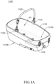
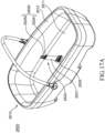
- FIG. 1A is a perspective view of the carrier 1100 of this embodiment
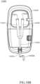
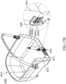
- FIG. 1B is a perspective view of the carrier 1100 viewed from bottom portion
- FIG. 1C is an enlarged view of a dashed-line framed area 1100A in FIG. 1B
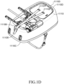
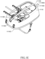
- FIGS. 1D and 1E are perspective views of variations of the aforementioned embodiment viewed from bottom portion.
- the carrier 1100 of this embodiment mainly includes a box body (also called “main body”) 1110, a handle 1120 and a fixing device 1130 (also referred to as a "first fixing device”).
- the box body 1110 is a box-shaped structure with a raised peripheral wall to enclose and define a carrying space S1, which may carry an infant, or an animal (or a pet).
- the box body 1110 has two opposite long sides 1110A and 1110B.
- the long side 1110A is a side where the box body 1110 abuts against a backrest of a vehicle seat (e.g., a rear seat).
- the handle 1120 is approximately in a U-shaped structure, which is linked to the box body 1110 in a movable or detachable way, so that a user (such as an infant caregiver or an animal owner) can conveniently draw and carry the carrier 1100 of this embodiment.
- two ends of the handle 1120 are pivotally connected to two respective long sides of the box body 1110, that is, the two ends of the handle 1120 may rotate to an upper edge of a peripheral wall of the box body 1110 along pivots 1121, 1122 to a direction of the box body 1110, to be stacked on the peripheral wall of the box body 1110 and be convenient for storage.
- the handle 1120 may also be detached from the box body 1110.
- the pivots of the handle 1120 may also be provided on outer surfaces of the two sides of the box body 1110, instead of upper edges of the two long sides of the box body 1110, to reduce the chance of the handle 1120 and its pivots colliding with an animal in the box body 1110, and avoid the animal from colliding with the handle 1120 due to the change of vehicle speed during driving, and then being frightened or injured.
- the carrier 1100 is fixed to the vehicle seat by a fixing device 1130.
- the carrier 1100 of this embodiment has a fixing device 1130 combined with the box body 1110, that is, the fixing device 1130 is directly provided (e.g., embedded) at a bottom portion of the box body 1110.
- the fixing device 1130 may be, for example, a rigid ISOFIX system, which includes a primary frame 1131, a connecting frame 1132, connectors 1133, 1134 (e.g., ISOFIX connectors), and a pulling belt 1135.
- the primary frame 1131 is directly fixed to the bottom portion of the box body 1110, for example, but not limited to, by a fixing way of embedding, locking or welding, etc.
- the connecting frame 1132 is U-shaped and consists of a pair of longitudinal connecting brackets 11321, 11322 and a transverse rod 11323 connecting the longitudinal connecting brackets 11321, 11322.
- Respective ends (or referred to as "back ends") of the two longitudinal connecting brackets 11321, 11322 are movably connected to the primary frame 1131, for example, by a socket mode, to enable the connecting frame 1132 to be telescopically moved relative to the primary frame 1131, so that the connectors 1133 and 1134 provided at a front end of the connecting frame 1132 may act between a position at the bottom portion of the box body 1110 and a position exposed from the long side 1110A of the box body 1110.
- the pulling belt 1135 is connected to a transverse rod 11323 of the U-shaped connecting frame 1132 for a user (such as an infant caregiver or an animal owner) to pull to drive the connecting frame 1132 to move relative to the primary frame 1131.
- the connectors 1133 and 1134 are used to connect to a corresponding fixing system at the vehicle seat, such as an ISOFIX fixing point, to stably fix the carrier 1100 of this embodiment to the vehicle seat.
- the fixing device 1110 of the carrier 1100 does not include the pulling belt 1135, and the user may adjust the positions of the connectors 1133 and 1134 by directly pulling the connectors 1133 and 1134.
- the "longitudinal” and “transverse” of the "longitudinal connecting bracket” and “transverse rod” correspond to the relative direction of the carrier, which is convenient to distinguish some parts and/or elements, that is, the "longitudinal connecting bracket” and the “transverse rod” may also be called a “first connecting bracket” and a “second connecting bracket”.
- a short side 1110C of the box body 1110 far away from the bottom board openings 1101 and 11102 is provided with a positioning buckle, through which a free end (not shown) of the fixing pulling belt may passes, and an adjusting end is formed there for the user to adjust the tightness of the fixing pulling belt.
- the fixing device 1130 of the carrier 1100 further includes a lock release handgrip 1136, which is also directly provided at the bottom portion of the box body 1110 of the carrier 1100.
- a lock release handgrip 1136 When the lock release handgrip 1136 is pulled, engagement pins 1136A and 1136B may be disengaged from an engagement hole (for example, an engagement hole 11322A) on the primary frame 1131 and one of engagement holes on the connector 11322 corresponding to the engagement hole of the primary frame 1131, respectively.
- an engagement hole for example, an engagement hole 11322A
- the connecting frame 1132 By pulling the pulling belt 1135, the user may make the connecting frame 1132 be stretched to move toward an outside of the box body 1110 relative to the primary frame 1131.
- the adjusting handgrip 1136 is loosened, so that the engaging pins 1136A and 1136B may be reset and inserted into the corresponding engagement holes of the primary frame and the connecting frame for positioning, and further movement of the connecting frame 1132 can be avoided.
- the connecting frame 1132 may be pushed to be folded, so that the connectors 1133 and 1134 may be disengaged from a rear seat fixing point after the lock is released (as described below).
- the fixing device 1130 of the carrier 1100 of this embodiment further includes a lock release device, which is also directly provided at the bottom portion of the box body 1110 of the carrier 1100 and is composed of a lock release mechanism 1137 connected with lock release linkage steel wires 1138A, 1138B.
- a lock release device which is also directly provided at the bottom portion of the box body 1110 of the carrier 1100 and is composed of a lock release mechanism 1137 connected with lock release linkage steel wires 1138A, 1138B.
- One end of each of the lock release linkage steel wires 1138A, 1138B is connected to the lock release mechanism 1137, and the other end of each of the lock release linkage steel wires 1138A and 1138B is connected to a lock block (not shown) of each of the connectors 1133, 1134.
- the fixing device 1130 of the carrier 1100 is directly fixed or embedded in the bottom portion of the box body 1110, so the box body 1110 of the carrier 1100 may be directly and stably fixed to the vehicle seat without matching with another fixing base or a base with supporting leg, and thereby completing a stable installation of the carrier 1100 in the vehicle.
- a positioning buckle 11103 of the carrier 1100 may be provided at the bottom portion of the box body 1110 and on a short side 1110D near the bottom board openings 11101, 11102.
- two ends of a Y-shaped fixing pulling belt pass through the bottom board openings 11101, 11102 respectively and are exposed out of a carrying space of the box body 1110 for fixing an infant and an animal (which will be further illustrated in FIGS. 10A and 10B , and FIGS. 11A and 11B ).
- a belt body part (also called a fixing strap) 11106 of the Y-shaped fixing pulling belt extends through a guide structure 11105 provided at the short side 1110C to change its extending direction, extends toward the short side 1110D and further passes through the positioning buckle 11103 provided at the short side 1110D.
- An adjusting end 11106A is formed for the user to adjust the tightness of the fixing pulling belt.
- the short side 1110D is a side close to the head of an infant or an animal, and also a side close to a caregiver in the rear seat.
- the carrier 1100 of this embodiment can facilitate the caregiver to adjust the tightness of the fixing belt according to the actual situation during driving, and to avoid the infant or the animal in the carrying space from being excessively pressed by the fixing belt.
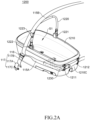
- FIGS. 2A to 2B a carrier 1200 with an integrated fixing device according to another embodiment of the first aspect of the present disclosure is schematically illustrated.
- FIG. 2A is a perspective view of the carrier 1200 of this embodiment
- FIG. 2B is a perspective view of the carrier 1200 viewed from the bottom portion.
- the carrier 1200 shown in FIG. 2A has a similar structure and composition to the carrier 1100 of the foregoing embodiment, including a box body 1210, a handle 1220 and a fixing device 1230.
- the box body 1210 is a box-shaped structure with a raised peripheral wall to enclose and define a carrying space S1.
- the handle 1220 is approximately in a U-shaped structure, which is linked to the box body 1210 in a movable or detachable way, so that a user (such as an infant caregiver or an animal owner) can conveniently draw and carry the carrier 1200 of this embodiment.
- the carrier in addition to the carrier 1200 being fixed to the corresponding ISOFIX fixing point of the rear seat of the vehicle by the fixing device 1230, and when the carrier is provided on the rear seat of the vehicle, the carrier may also be fastened by using the safety belt belly belt (or the waist belt) 115A of the rear seat of the vehicle passing through the guide elements 1211, 1212 on the periphery of the short side 1210C of the box body 1210, and the shoulder belt 115B of the safety belt passing through the guide element 1223 on the handle 1220, which are connected together and inserted into a corresponding female buckle (not shown) at the rear seat by means of their jointly connected tongue piece 116.
- the safety belt belly belt or the waist belt
- the combination of the safety belt in the rear seat of the vehicle with the box body 1210 and the handle 1220 may provide the stable and fixed effect for the carrier 1200 of this embodiment.
- the guide element 1223 on the handle 1220 limits the shoulder belt 115B of the safety belt on the handle 1220, which is beneficial to make the shoulder belt 115B of the safety belt fit with a part of the handle 1220 and extend along it. Therefore, the handle 1220 may also provide auxiliary support for the shoulder belt 115B of the safety belt and prevent the shoulder belt 115B from moving randomly when the vehicle is traveling.
- the carrier 1200 of this embodiment further includes an extension belt 117 provided on an outer surface of the box body.
- an extension belt 117 provided on an outer surface of the box body.
- the extension belt 117 includes an extension strap 117A, the ends of which are respectively connected with a female buckle fastening element 117B and a male buckle fastening element (e.g., a tongue piece) 117C.
- a female buckle fastening element 117B After passing through the guide elements 1211, 1212 on the box body 1210 and the guide element 1223 on the handle 1220 respectively, the belly belt 115A and the shoulder belt 115B of the safety belt of the rear seat of the vehicle are inserted into the female buckle fastening element 117B of the extension belt 117 by their jointly connected tongue piece 116, and further inserted into the female buckle of the vehicle safety belt by the male buckle fastening element 117C (e.g., a tongue piece) of the extension belt 117, so that the seat belt of the rear seat of the vehicle is used to fix the rear seat of the vehicle to complete the stable installation of the carrier 1200 in the embodiment.
- the male buckle fastening element 117C e.g., a tongue piece
- the carrier 1300 has a structure and composition similar to those of the carriers 1100, 1200 of the foregoing embodiment, including a box body 1310, a handle 320, guides 1311, 1312 and 1323, and an extension belt 117, an extension strap 117A, a female buckle fastening element 117B, a male buckle fastening element 117C, etc.
- similar reference numerals are used to indicate the same functions or components, and the same parts will not be repeated to avoid confusing the inventive concept.
- This embodiment is different from the carrier 1200 shown in FIGS.
- the carrier 1300 is not provided with the ISOFIX fixing device 1230, but is directly fixed to the rear seat of the vehicle by the rear seat safety belt.
- the carrier 1300 may be fixedly installed in the vehicle by fixing the rear seat of the vehicle with the rear seat safety belt of the vehicle.
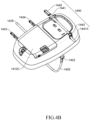
- FIGS. 4A to 4C a carrier 1400 with an integrated fixing device according to an embodiment of the first aspect of the present disclosure is schematically illustrated.
- FIG. 4A is a perspective view of the carrier 1400 of this embodiment
- FIG. 4B is a perspective view of the carrier 1400 viewed from bottom portion
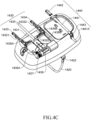
- FIG. 4C is also a perspective view of the carrier 1400 viewed from bottom portion.
- a bottom cover 1410C of the box body 1410 is removed to reveal the composition and assembly of the fixing device 1430 of the carrier 1400.
- the carrier 1400 shown in FIGS. 4A to 4C has a similar structure and composition to the carriers 1100, 1200 of the foregoing embodiments, including a box body 1410, a handle 1420 and a fixing device 1430.
- the box body 1410 is a box-shaped structure with a raised peripheral wall to enclose and define a carrying space S1.
- the handle 1420 includes pivots 1421, 1422.
- the fixing device 1430 includes a primary frame 431, longitudinal connecting brackets 14321, 14322 connecting to the frame, connectors 1433, 1434, a transverse rod 14323, a pulling belt 1435, a lock release handgrip 1436, engagement pins 1436A, 1436B, a lock release mechanism 1437, and lock release linkage steel wires 1438A, 1438B.
- the carrier 1400 includes not only the above-mentioned fixing device 1430 as the first fixing device, but also a second fixing device 1440, which is, for example, a soft ISOFIX system, to provide another fixing point for the carrier 1400 to the rear seat.
- a second fixing device 1440 which is, for example, a soft ISOFIX system
- the second fixing device 1440 includes a belt portion 1441 (e.g., a webbing) and a connector 1442 connected to an end of the belt portion 1441.
- the connector 1442 may be, for example, an ISOFIX connector, which may be connected to a corresponding ISOFIX fixing point of the rear seat of the vehicle.
- the belt portion 1441 extends at the bottom portion of the box body 1410, and the other end (an adjustment end) 1441A is exposed outside the box body 1410 through an adjuster 1443 provided at a long side 1410B of the box body 1410, so that the user can quickly and simply adjust a belt length of the belt portion 1441 of the flexible (soft) connection fixing system 1440.
- the carrier 1400 may also include guide elements correspondingly provided on the outer surface of the box body 1410 and the handle 1420, as like the guide elements 1211, 1212 and 1223 in the foregoing embodiment, through which the safety belt (not shown) of the vehicle seat pass and positioned therein, to provide further stable and fixed effect for the carrier 1400.
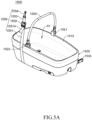
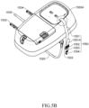
- FIG. 5A is a perspective view of the carrier 1500 of this embodiment
- FIG. 5B is a perspective view of the carrier 1500 viewed from bottom portion
- FIG. 5C is an enlarged view of a bearing surface in the box body carrying space corresponding to a dashed-line area 1500A in FIG. 5B
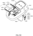
- FIG. 5D is a schematic view of the carrier 1500 of this embodiment showing the composition and components of the fixing device 1530 after removing a bottom cover of the box body 1510.
- the carrier 1500 shown in FIGS. 5A to 5D has a similar structure and composition to the carriers 1100, 1200 and 1400 of the foregoing embodiments, including a box body 1510, a handle 1520 and a fixing device 1530.
- the box body 1510 is a box-shaped structure with a raised peripheral wall to enclose and define a carrying space S1.
- the handle 1520 includes pivots 1521, 1522.
- the fixing device 1530 includes a primary frame 1531, a connecting frame 1532, longitudinal connecting brackets 15321, 15322, connectors 1533, 1534, a transverse rod 15323, a pulling belt 1535, a lock release handle 1536, locking pins 1536A, 1536B, a lock release mechanism, a lock release linkage steel wire and the like.
- the carrier 1500 further includes an anchoring device (a top tether) 1550 in addition to the above-mentioned fixing device 1530 to further fix the carrier 1500 to an anchoring point (not shown) in the rear seat of the vehicle.
- the anchoring device 1550 includes a tether 1551, an adjuster 1552, a connecting strap 1553 and a connecting element 1554 (such as a hook element).
- a length of the connecting strap 1553 is fixed, and the user may pull the tether adjusting end 1551A passing through the adjuster 1552 to adjust a length of the tether 1551 in coordination with the fixing of the adjuster 1552, to adjust the overall belt length of the anchoring device 1550 to adapt to a position of the fixing point.
- the length of the tether 1551 may be fixed, and the user uses the adjuster 1552 to adjust the length of the connecting strap 1553, thereby adjusting the overall belt length of the anchoring device 1550 to adapt to the fixing point of the rear seat of the vehicle.
- an end of the tether 1551 of the anchoring device 1550 passes through a through hole 1510S on the box body 1510 inward from an outer surface of the bottom portion of the box body 1510, and is abutted against an inner surface of the box body 1510 by a fixing element (for example, but not limited to, a tri-glide buckle, such as a fixing element 1555) connected to the end of the tether 1551.
- the fixing element 1555 is exposed from the inner surface of the box body 1510 out of the carrying space S1 surrounded by the peripheral wall of the box body 1510.
- the carrier 1500 may also include guide elements correspondingly provided on the outer surface of the box body 1510 and the handle 1520, as like the guide elements 1211, 1212 and 1223 in the foregoing embodiment, through which the safety belt (not shown) of the vehicle seat or the tether 1551 of the anchoring device 1550 may pass and be positioned therein, to provide further stable and fixed effect for the carrier 1500.
- a carrier 1600 with an integrated fixing device according to an embodiment of the first aspect of the present disclosure is schematically illustrated.
- the carrier 1600 shown in FIG. 6 has a structure and composition similar to that of the carrier 1500 of the foregoing embodiment, including a box body 1610, a carrying space S1 defined by the box body 1610, a handle 1620, pivots 1621, 1622 of the handle 1620, a fixing device including a connector 1633 and other components, and an anchoring device 1650.
- the connector 1633 is an ISOFIX connector, and connecting ends of which have directionality, that is, a thick end 1633A located above and a relatively thin end 1633B located below.
- the connector 1633 also includes a lock release button 1633C for the user to press to release the connector 1633, so that it may be separated from the ISOFIX fixing point of the vehicle seat.
- the fixing device of the carrier may change its connection direction to be adaptively fixed to a corresponding fixing point of a left vehicle seat (i.e., behind a driver's seat) or a right vehicle seat (i.e., behind an assistant seat). As described in detail in FIGS. 7A to 7D below.
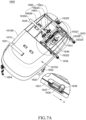
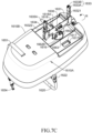
- FIGS. 7A to 7E the detailed structure and action of the fixing device in the carrier 1600 of the embodiment shown in FIG. 6 are schematically illustrated.
- the carrier 1600 of this embodiment has a fixing device combined with a box body 1610. That is, the fixing device is directly provided at the bottom portion of the box body 1610, so that the carrier 1600 of this embodiment may be directly and fixedly installed to the rear seat of the vehicle without any additional fixing base or base with supporting leg.
- the fixing device may be, for example, a rigid ISOFIX system, which includes a primary frame 1631, a connecting frame including longitudinal connecting brackets 16321, 16322, and a transverse rod 16323, connectors 1633, 1634, and a linkage assembly 1670 including a pulling belt 1635.
- the carrier 1600 of this embodiment further includes a steering device 1660, and the fixing device is connected to the steering device 1660 through the primary frame 1631 to pivot to the bottom portion of the box body 1610, and the fixing device may pivot from an original first region to a second region at the bottom portion of the box body 1610 through the steering device 1660.
- the fixing device may change its connection direction to the rear seat of the vehicle, to be adaptively fixed to the corresponding fixing point on the left side (i.e., behind the driver's seat) or the right side (i.e., behind the assistant seat) of the rear seat.
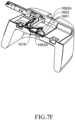
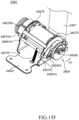
- FIG. 7F it schematically illustrates the detailed structure of the steering device of this embodiment.
- the steering device 1660 includes a pivot 1661, lugs 1662A and 1662B, and a circular turntable 1663.
- a circular groove 1616 is formed at the bottom portion of the box body of the carrier 1600, which accommodates the circular turntable 1663 of the steering device 1660 and serves as a space for the steering device 1660 to act.
- the circular turntable 1663 may rotate in the circular groove with a rotation center 1663A.
- the rotation center 1663A is a central axis where a center of the circular groove 1616 (not shown) and a center of the circular turntable 1663 are coincided.
- the pivot 1661 is fixed in a diameter direction of the circular turntable 1663 through lugs 1662A and 1662B (marked in FIG. 7A ), so that the pivot 1661 may rotate with the rotation of the circular turntable 1663.
- the pivot 1661 passes through the lugs 1662A and 1662B and has a gap with the bottom portion of the box body, so that the primary frame 1631 connected to the pivot 1661 also has a gap with the bottom portion of the box body without contacting with the outer surface of the bottom portion of the box body. This gap provides an appropriate space for the primary frame 1631 to turn over (as described below).
- annular guide rail may also be formed at the bottom portion of the box body 1610.
- the steering device 1660 includes a pivot, and a pair of guide lugs at the outer side of the pivot and close to two ends of the pivot.
- the guide lugs are respectively engaged with the annular guide rail with their outer edges and may move along the annular guide rail, thereby driving the pivot to rotate around a center of the annular guide rail.
- a side of the primary frame 1631 of the fixing device is connected to the pivot 1661.
- the primary frame 1631 also has a gap from the outer surface of the bottom portion of the box body 1610, so that the primary frame 1631 may rotate along the pivot 1661 to drive the connecting frame, connectors 1633, 1634 to turn toward a relative long side of the box body 1610 (further explained below).
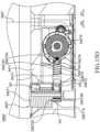
- the primary frame 1631 of the fixing device is provided with a steering lock release mechanism, which includes an operating element 1636, a locking pin 1637 and a reset spring 1638 sleeved outside the locking pin 1637.
- the locking pin 1637 may engage with an engagement hole (to be described later) on the inside of an accommodating slot at the bottom portion of the box body 1610, and the primary frame 1631 is positioned at the bottom portion of the box body 1610 by engaging the locking pin 1637 with the engagement hole.
- an operating element 1636 of the steering lock release handgrip in an arrow direction U shown in the enlarged view of FIG. 7A
- the locking pin 1637 is driven to move in the same direction, thereby unlocking the primary frame 1631, and the primary frame 1631 is released from its position on the bottom portion of the box body 1610 and is in an operable state.
- the locking pin 1637 is restored by a restoring elastic force of a reset spring 1638, and may be engaged with the corresponding engagement hole, so that the primary frame 1631 may be positioned relative to the box body 1610.
- the carrier 1600 of this embodiment may be fixed to the ISOFIX fixing point of a left vehicle seat (i.e., behind the driver's seat) with connectors 1633, 1634 provided on a long side 1610A of the carrier 1600, and may be further fixed to a corresponding fixing point above the rear seat of the vehicle or over the seat to the rear bottom portion through a tether 1651, a connecting strap and a connecting element (e.g., a hook element) 1654 of an anchoring device of the carrier 1600, taken as an anchoring point.
- a connecting strap and a connecting element e.g., a hook element
- the user When the user wants to fix the carrier 1600 to the right vehicle seat according to the actual application, the user first presses the lock release button 1633C of the connector 1633 (as shown in FIG. 6 ) to release the connector 1633 and presses the lock release button 1634 of the connector 1634 (not shown) to release the connector 1634, so that the connectors 1633, 1634 are separated from the ISOFIX fixing point of the vehicle seat. Then, the operating element 1636 of the steering lock release mechanism is pushed or pulled, so that the locking pin 1637 is disengaged from the engagement hole 1617A (as shown in FIG. 7B ) in the accommodating slot 1617, and the primary frame 1631 may be released.
- the user pulls the adjusting end 1635A of the pulling belt 1635, to release the linkage assembly 1670.
- the primary frame 1631 together with the connecting frame and connectors 1633, 1634 may be pulled up, so that the primary frame 1631 of the fixing device together with the connecting frames and connectors 1633, 1634 may be turned over from the originally located first region to a vertical plane at the bottom portion of the box body 1610 along the pivot 1661, so that the primary frame 1631 of the fixing device together with the connecting frame and connectors 1633, 1634 presents an upright state as shown in FIG. 7C .
- the linkage assembly 1670 includes a pair of sliding blocks 1672A, 1672B, a reset spring 1671 provided between the sliding blocks 1672A, 1672B, and a pulling belt 1635.
- the pulling belt 1635 has a Y-shaped structure, and connecting belts 16351, 16352 at both ends are connected with the sliding blocks 1672A, 1672B respectively, so that the sliding blocks 1672A, 1672B may be driven, and the sliding blocks 1672A, 1672B are pushed by the pulling belt 1635 to press the reset spring 1671 and move toward each other, thereby disengaging the locking pins 1676A, 1676B of the linkage assembly 1670 from the engagement holes (not shown) of the longitudinal connecting brackets 16321, 16322, respectively, and releasing the longitudinal connecting brackets 16321, 16322 of the connecting frame.
- the connecting belts 16351, 16352 at both ends of the pulling belt 1635 may be connected with corresponding ring elements 1670A, 1670B on the sliding blocks 1672A and 1672B respectively, for example, by threading and sewing, to move the sliding blocks 1672A, 1672B when being pulled to release the connecting frame from the bottom portion of the box body 1610.
- the primary frame 1631 together with the connecting frame and connectors 1633, 1634 may be pulled up, so that the primary frame 1631 may be turned over from the originally located first region to the vertical plane at the bottom portion of the box body 1610 along the pivot 1661, and the primary frame 1631 of the fixing device together with the connecting frames and connectors 1633, 1634 may be in an upright state as shown in FIG. 7C .
- the circular turntable 1663 of the steering device 1660 rotates along the central axis 1663A in the circular groove 1616 of the box body 1610 or moves in the annular guide rail by using the guide lug, which drives the primary frame 1631 connected with the steering device 1660 to rotate counterclockwise (as shown by the arrow direction R in FIG. 7C ) by 180 degrees, and the pulling belt 1635 rotates with the primary frame 1631, and the adjusting end 1635A of the pulling belt 1635 is shifted from extending out of the long side 1610B to extending out of the long side 1610A.
- the primary frame 1631 is turned over to a parallel plane of the bottom portion of the box body 1610 along the pivot 1661 and then abuts against a second region of the bottom portion of the box body 1610.
- the sliding blocks 1672A, 1672B of the linkage assembly 1670 are reset to both sides by the restoring force of the reset spring 1671 to push the locking pins 1676A, 1676B to engage with the engagement holes of the longitudinal connecting brackets 16321, 16322, respectively.
- the user can pull the operating element 1636 of the steering lock release mechanism, and the locking pin 1637 is reset and locked in the engagement hole 1618A of the accommodating slot 1618, so that the fixing device presents a state as shown in FIG.
- the linkage assembly 1670 further includes a first wall 16701 and a second wall 16702, and the first wall 16701 has two openings 16701A, 16701B.
- the first wall 16701 and the second wall 16702 form a track 16703 for the sliding blocks 1672A, 1672B to move stably, and the openings 16701A, 16701B of the first wall 16701 may be used for the webbing fixing portions of the sliding blocks 1672A, 1672B to expose respectively, so that the connecting belts 16351, 16352 may be connected to the sliding blocks 1672A, 1672B through two webbing fixing portions, respectively.
- a direction of the tether 1651 of the anchoring device 1650 is adjusted so that the tether 1651, an adjuster 652, a connecting strap 653 and a connecting element 1654 extend from the periphery of the bottom portion of the box body 1610 toward the long side 1610A, as shown in FIG. 7E .
- the positions of the connectors 1633, 1634 have been changed from extending out of the long side 1610A to extending out of the long side 1610B, so that the carrier 1600 of this embodiment may be fixed to the ISOFIX fixing point of the right vehicle seat (that is, behind the assistant seat) with the connectors 1633, 1634 provided on the long side 1610B, and may be further fixed to a corresponding fixing point above the rear seat of the vehicle or over the seat to the rear bottom portion through a tether 1651, a connecting strap 653 and a connecting element 1654 the an anchoring device of the carrier 1600, taken as an anchoring point.
- the length of the tether 1651 of the anchoring device 1650 may be adjusted to adapt to the fixing point position of the vehicle.
- an anchoring device 1850 of the carrier 1800 is formed in a Y-shaped structure.
- the anchoring device 1850 mainly includes a first tether 18511 and a second tether 18512, an adjuster 1852 and a connecting strap 1853.
- An end of the first tether 18511 and an end of the second tether 18512 are connected to the same side of the adjuster 1852, or the end of the first tether 18511 and the end of the second tether 18512 are combined (e.g., by sewing) into a tether 1851 in order to be connected to the same side of the adjuster 1852.
- the carrier 1800 is fixed to the corresponding ISOFIX fixing point of the rear seat of the vehicle by the fixing device (e.g., through the connector 1833 of the fixing device) of the carrier 1800, and when carrier 1800 is provided on the rear seat of the vehicle, the combination of the tether of the anchoring device 1850 with the box body 1810 and the handle 1820 may further provide a stable and fixed effect of the carrier 1800 of this embodiment.
- the fixing device e.g., through the connector 1833 of the fixing device
- the fixing device and the anchoring device 1850 are integrated through a connection of the tether and the connecting bracket.
- the fixing device and the anchoring device 1850 may also be independent devices or components, which provide the carrier with fixing and anchoring functions respectively.
- the first positioning structure 1817 is formed with a transverse portion 18171 and a longitudinal portion 18172, and the longitudinal portion 18172 is connected at a center of the transverse portion 18171 and has a narrow width, so that a left positioning slot 1817A and a right positioning slot 1817B are formed on both sides of the longitudinal portion 18172 at the joint of the transverse portion 18171 and the longitudinal portion 18172.
- the longitudinal portion 18182 of the second positioning structure 1818 is connected to the center of a transverse portion 18181 and has a relatively narrow width, so that a left positioning slot 1818A and a right positioning slot 1818B are formed on both sides of the longitudinal portion 18182 at the joint of the transverse portion 18181 and the longitudinal portion 18182.
- the first belt 11071 and the second belt 11072 respectively protrude from a first bottom board opening 11011 and a second bottom board opening 11012 which are formed at the bottom portion of the box body 11010 and penetrate through the bottom portion, and ends of which are connected with respective fastening elements 11071A, 11072A, for example, a tongue piece or other forms of male buckle fastening elements.
- the first belt 11071 and the second belt 11072 are respectively buckled with a buckle (such as a safety belt female buckle) 11075A on the fixing buckle belt (also called "box belt”) 11075 through their respective fastening elements 11071A, 11072A, and thereby forming a closed fixing structure and providing corresponding fixing and support for the shoulder of the infant.
- a buckle such as a safety belt female buckle
- box belt also called "box belt”
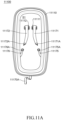
- FIGS. 11A and 11B a carrier for transporting an animal or a pet according to an embodiment of the first aspect of the present disclosure is schematically illustrated.
- FIG. 11A is a schematic front view of the carrier 11100 of this embodiment
- FIG. 11B is a schematic back view of the carrier 11100 of this embodiment.
- a fixing pulling belt of the carrier 11100 includes a first belt 11171 and a first belt 11172 (also called a “back belt”), and a main pulling belt 11170 (similar to the "belt body part 11106" in the foregoing embodiment, also called a "fixing strap") connected to the respective fixing ends of the first belt 11171 and the second belt 11172, and thereby presenting a Y structure.
- the first belt 11171 and the second belt 11172 respectively protrude from a first bottom board opening 11111 and a second bottom board opening 11112, which are formed at the bottom portion of the box body 11110 and penetrate through the bottom portion, and ends of the belts are connected with respective fastening elements (i.e., a tongue piece or other forms of male buckle fastening elements) 11171A, 11172AB.
- respective fastening elements i.e., a tongue piece or other forms of male buckle fastening elements
- the first belt 11171 and the second belt 11172 are respectively buckled with buckles (i.e., safety belt female buckles) 11175A, 11176A at one end of fixing buckle belts 11175, 11176 through their respective fastening elements 11171A, 11172A, and thereby forming a closed fixing structure and providing corresponding fixing and support for the shoulder and back of the animal. As shown in FIG.
- the first belt 11171 and the second belt 11172 extend on the back of the box body 11110 and are jointly connected to one end of the main pulling belt 11170, and the other end (i.e., a free end) of the main pulling belt 11170 further extends through the positioning buckle 11113 provided on the short side of the box body 11110, and an adjusting end 1170a is exposed there, so that the user may adjust the tightness of the fixing pulling belt by pulling the adjusting end 1170a and positioning the positioning buckle 11113.
- the carrier 11000 and the fixing pulling belt in the carrier 11100 may be applied to the carriers of the above-mentioned multiple embodiments, and the present disclosure does not limit to the possible combined embodiments of the above-mentioned carriers.
- the positioning buckle on the short side of the box body may also be replaced by the guide structure 11105 shown in FIGS. 1D and 1E , and a positioning buckle 11103 is provided on the other short side, so that it is convenient for the caregiver to adjust the tightness of the fixing pulling belt at any time.
- box body shapes of the carriers are all cuboids
- the present disclosure does not limit to the shape of the box body of the carrier, and they may also be cubes, instead of having two long sides and two short sides, they have four sides with roughly equal lengths.
- integrated fixing device or “integrated-type fixing device” means that the fixing device of the carrier of the present disclosure is directly fixed or embedded in the bottom portion of the box body and combined with the box body of the carrier, so that the carrier of the present disclosure may be directly fixed on the vehicle seat with the box body itself.
- the first aspect of the present disclosure provides a carrier with an integrated fixing device and a corresponding fixing device.
- the fixing device of the carrier is directly fixed or embedded in the bottom portion of the box body, so the box body may be directly and stably fixed to the rear seat of the vehicle without matching with an additional fixing base, and thereby completing the stable installation of the carrier in the vehicle.
- the first aspect of the present disclosure also provides a carrier with changeable fixing direction.
- the fixing device of the carrier of the present disclosure the user can quickly and easily fix the carrier to the left side (i.e., behind the driver's seat) or the right side (i.e., behind the assistant seat) of the rear seat of the vehicle according to the actual application requirements.
- a carrier in particular a pet carrier
- a carrier in particular a pet carrier
- similar structures in the following different embodiments have similar reference numerals.
- the reference numerals of pet carriers in the first embodiment to the eighth embodiment according to the second aspect of the present disclosure are "2100" to "2800" respectively.
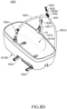
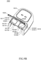
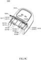
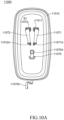
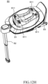
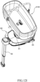
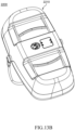
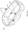
- FIGS. 12A and 12B are schematic appearance views of a pet carrier 2100 according to a first embodiment in the second aspect of the present disclosure from different view angles.
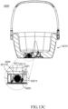
- FIG. 12C is a schematic sectional view of the pet carrier according to the first embodiment of the second aspect of the present disclosure.
- FIG. 12D is a schematic view of a binding device 2120 according to the first embodiment of the second aspect of the present disclosure.
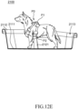
- FIGS. 12E and 12F are schematic views of the pet carrier in different use states according to the first embodiment of the second aspect of the present disclosure.
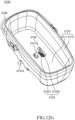
- FIG. 12G is a schematic view of the pet carrier according to the first embodiment of the second aspect of the present disclosure when the handle is folded. As shown in FIG. 12A to FIG.
- the pet carrier 2100 includes a box body 2110 and a binding device 2120, and the box body 2110 includes a bottom portion 2111 and a peripheral wall 2112 connected with the bottom portion 2111, the bottom portion 2111 and the peripheral wall 2112 surround to define an accommodation space 2113 for accommodating a pet, the bottom portion 2111 includes a bottom opening 21111, and the binding device 2120 includes a binding webbing 2121.
- the binding webbing 2121 passes through the bottom opening 21111 and is at least partially located in the accommodating space 2113.
- the binding webbing 2121 may be used to cooperate with a connecting element provided on a pet vest P0 worn by the pet, to limit the pet in the accommodating space 2113, and the connecting element may be a fixing ring, such as a metal ring, a webbing ring or a buckle ring made of other materials that can bear high tension.
- the box body 2110 may have a substantially rectangular structure, but the present disclosure is not limited thereto. In another embodiment, the box body may have a substantially square structure.
- the binding webbing 2121 may pass through a connecting element P1 on the pet vest P0 near a back of the pet or the connecting element P2 on the pet vest P0 near a chest or belly of the pet, so that the binding webbing 2121 may cooperate with the corresponding connecting element, but the present disclosure is not limited thereto, and the binding webbing may pass through any connecting element on the pet vest.
- the binding device 2120 further includes a buckle assembly 2122 that includes a first buckle element 21221 and a second buckle element 21222.
- the first buckle element 21221 and the second buckle element 21222 may be a male buckle and a female buckle, respectively.
- the first buckle element 21221 is provided at a free end 21211 of the binding webbing 2121.
- the second buckle element 21222 is provided at the bottom portion 2111 of the box body 2110.
- the free end 21211 of the binding webbing 2121 is detachably connected with the bottom portion 2111 of the box body 2110 through an engagement of the first buckle element 21221 and the second buckle element 21222.
- the binding device 2120 further includes an adjuster 2123, through which the binding webbing 2121 penetrates. An adjusting end 21212 of the binding webbing 2121 is exposed out of the adjuster 2123.
- the adjuster 2123 is used to lock the binding webbing 2121 so that the binding webbing 2121 cannot move relative to the adjuster 2123, and the adjuster 2123 is also used to release the binding webbing 2121, so that the binding webbing 2121 can move relative to the adjuster 2123, to allow the user to pull the free end 21211 or the adjusting end 21212 according to actual needs (such as the size of a pet) to adjust the length of the binding webbing 2121 in the accommodating space 2113.
- the bottom opening 21111 may penetrate through the bottom portion 2111 of the box body 2110, and the adjuster 2123 may be provided on the outer surface of the box body 2110 and close to the long side of the bottom portion 2111 of the box body 2110, to facilitate the user's operation and avoid being touched by the pet mistakenly.
- the user may first operate the adjuster 2123 (e.g., press a button 21231 of the adjuster 2123 to pivot in an arrow direction as shown in FIG. 12C ) to release the binding webbing 2121, and then penetrate the binding webbing 2121 through the connecting element P1 on the pet vest P0 near the back of the pet or the connecting element P2 on the pet vest P0 near the chest or belly of pet, so that the binding webbing 2121 may cooperate with the connecting element P1 or the connecting element P2.
- the adjuster 2123 e.g., press a button 21231 of the adjuster 2123 to pivot in an arrow direction as shown in FIG. 12C
- the user may fasten the first buckle element 21221 to the second buckle element 21222, so that the free end 21211 of the binding webbing 2121 may be detachably connected to the bottom portion 2111 of the box body 2110.
- the adjuster 2123 is operated (for example, the button 21231 of the adjuster 2123 is released to pivot in the direction opposite to the arrow as shown in FIG. 12C ) to lock the binding webbing 2121, thereby achieving the purpose of limiting the pet in the accommodating space 2113 and improving the pet's riding safety.
- FIG. 12H is a schematic view of a base B0 used with the pet carrier 2100 according to the first embodiment of the second aspect of the present disclosure
- FIG. 12I is a schematic view when the pet carrier 2100 according to the first embodiment of the second aspect of the present disclosure is installed on the base B0.
- the pet carrier 2100 further includes at least one engaging assembly.
- at least one engaging assembly includes a first engaging assembly 2130 and a second engaging assembly 2140, which are provided at the bottom portion 2111 of the box body 2110 and spaced apart from each other along a long axis direction of the box body 2110.
- the first engagement assembly 2130 includes a first engaging element 2131 and a second engaging element 2132.
- the second engagement assembly 2140 includes a third engaging element 2141 and a fourth engaging element 2142, which are spaced apart from each other along a short axis direction of the box body 2110.
- the first engaging element 2131 and the third engaging element 2141 are aligned with each other along a long axis direction of the box body 2110, and the second engaging element 2132 and the fourth engaging element 2142 are aligned with each other along the long axis direction of the box body 2110.
- the user may selectively adjust an installation orientation of the pet carrier 2100 with respect to the base B0 by making the first engaging element 2131 and the second engaging element 2132 engage into a corresponding engaging portion B11 of the engaging structure B1 or making the third engaging element 2141 and the fourth engaging element 2142 engage into a corresponding engaging portion B11 of the engaging structure B1, respectively.
- the user may choose to make the first engaging element 2131 and the second engaging element 2132 engage into the corresponding engaging portion B11 of the engaging structure B1, so that the pet carrier 2100 may be positioned at a position relative to the base B0 as shown in FIG. 12I .
- the pet carrier 2100 further includes two structural reinforcements 2150 and a handle 2160.
- the two structural reinforcements 2150 are provided at the bottom portion 2111 of the box body 2110 at intervals, and each structural reinforcement 2150 may be a convex rib with its long axis direction roughly parallel to the short axis direction of the box body 2110.
- the structural reinforcements 2150 may enhance a structural strength of the pet carrier 2100, in order to improve its impact resistance.
- the structure of the pet carrier of the present disclosure is not limited thereto.
- the pet carrier may only include one structural reinforcement.
- at least one of the structural reinforcements and the handle may be omitted.
- the handle may be detached from the peripheral wall.
- FIGS. 13A and 13B are schematic appearance views of a pet carrier according to a second embodiment of the second aspect of the present disclosure from different view angles.
- FIG. 13C is a schematic sectional view of the pet carrier according to the second embodiment of the second aspect of the present disclosure.
- FIG. 13D is a partial structural schematic view of a binding device according to the second embodiment of the second aspect of the present disclosure.
- the pet carrier 2200 of this embodiment includes a box body 2210 and a binding device 2220.
- the binding device 2220 of this embodiment includes a retractor 2224, but not include an adjuster.
- the binding device 2220 further includes a guide element 2225 that is close to the retractor 2224 and used for guiding the binding webbing 2221 to approach a turning section 22213 of the retractor 2224.
- the guide element 2225 has an arc surface for contacting with the binding webbing 2221, so that the turning section 22213 of the binding webbing 2221 has a smooth path, so that the winding or extension operation of the binding webbing is smoother.
- the binding device does not include a guide element.
- FIGS. 14A and 14B are schematic appearance views of a pet carrier according to a third embodiment of the second aspect of the present disclosure from different view angles
- FIG. 14C is a schematic sectional view of the pet carrier according to the third embodiment of the second aspect of the present disclosure.
- the pet carrier 2300 of this embodiment includes a box body 2310 and a binding device 2320.
- the bottom portion 2311 of the box body 2310 of this embodiment includes a body element 23113 and a rotating element 23114 that is rotatable relative to the body element 23113.
- FIGS. 15A and 15B are schematic appearance views of a pet carrier according to a fourth embodiment of the second aspect of the present disclosure from different view angles.
- FIG. 15C is a schematic sectional view of the pet carrier according to the fourth embodiment of the second aspect of the present disclosure.
- FIGS. 15D and 15E are partial internal structural schematic views of the pet carrier according to the fourth embodiment of the second aspect of the present disclosure.
- FIG. 15F is a partial structural schematic view of a binding device according to the fourth embodiment of the second aspect of the present disclosure.
- the pet carrier 2400 of this embodiment includes a box body 2410 and a binding device 2420.
- the binding device 2420 of this embodiment includes a hook 2426, but not include a buckle assembly.
- the hook 2426 is provided at a free end 24211 of the binding webbing 2421, and the hook 2426 buckles a connecting element on the pet vest, thereby enabling the binding webbing2421 to match with the connecting element on the pet vest.
- the binding device 2420 further includes a locking device 2427, which is used to lock the retractor 2424, and the retractor 2424 cannot rotate, so that the retractor 2424 cannot wind up or release the binding webbing 2421.
- the driving element 24272 is slidably provided at the bottom portion 2411 of the box body 2410 and includes a first end 24272A and a second end 24272B.
- the first end 24272A of the driving element 24272 is formed with a depression 24272C for matching with the first locking element 24274, and the second end 24272B of the driving element 24272 is formed with an accommodating slot 24272D for matching with the operating element 24271.
- the bottom portion 2411 of the box body 2410 is formed with a raised column 412 for the driving element 24272 to pass through and located between the first end 24272A and the second end 24272B.
- the elastic element 24273 is released to move the driving element 24272 in the first direction D1, so that the first end 24272A of the driving element 24272 drives the first locking element 24274 to engage with the corresponding locking notch 24275A in a first direction D1.
- the operating element 24271 is switched from the unlocked position as shown in FIG. 15E to the locked position as shown in FIG.
- the cam structure 24271A only contacts with a first side wall W1 of the accommodating slot 24272D and does not contact with a second side wall W2 of the accommodating slot 24272D, that is, an avoidance space S2 is formed between the cam structure 24271A and the second side wall W2 of the accommodating slot 24272D to allow the driving element 24272 to move in a second direction D2 opposite to the first direction D1.
- the retractor 2424 cannot be rotated.
- the cam structure 24271A of the operating element 24271 pushes against the first side wall W1 of the accommodating slot 24272D to move the driving element 24272 in the second direction D2, so that the avoidance space S2 is gradually reduced until the second side wall W2 of the accommodating slot 24272D contacts with the cam structure 24271A.
- the elastic element 24273 is elastically compressed, and the resetting element 24276 drives the first locking element 24274 to disengage from the corresponding locking notch 24275A in the second direction D2 to rotate the retractor 2424, that is, the pet carrier 2400 of this embodiment allows the user to operate the operating element 24271 of the locking device 2427 to lock the retractor 2424 according to actual needs, to limit the winding or extension of the binding webbing 2421, or to operate the operating element 24271 of the locking device 2427 to release the retractor 2424 to allow the binding webbing 2421 to be wound or extended.
- the structure of the locking device disclosed in the present disclosure is not limited thereto.
- the locking device may not include an elastic element and a resetting element, and the operating element is slidably provided at the bottom portion of the box body and used for sliding to drive the driving element to engage or disengage from the corresponding locking notch.
- the locking device may only include a second locking element at one side of the retractor, and the second locking element includes one or more locking notches.
- both ends of the resetting element 24276 are respectively connected with the first locking element 24274 and the bracket 24241 of the retractor 2424, and a side of the bracket 24241 close to the second locking element 2475 is formed with sliding slots 24241A through which corresponding ends of the first locking element 24274 may slide, and the long axis direction of each sliding slots 24241A is parallel to the first direction D1.
- the side of the bracket 24241 is also provided with a revolving element 24242 which can rotate relative to the bracket 24241.
- a skewed slot 24242A is formed on the revolving element 24242, and an extending direction of the skewed slot 24242A is inclined relative to the first direction D1.
- the binding webbing 2421 is pulled to rotate the revolving element 24242 in the arrow direction, through a coordination of the skewed slot 24242A, the sliding slot 24241A and the first locking element 24274, the first locking element 24274 may be moved along the first direction D1 to engage the locking notch 24275A, so that the binding webbing 2421 cannot extend.
- the binding webbing connected with the hook may also pass through the adjuster without connecting the retractor.
- FIG. 17A is a schematic appearance view of a pet carrier according to a sixth embodiment of the second aspect of the present disclosure
- FIG. 17B is a schematic sectional view of the pet carrier according to the sixth embodiment of the second aspect of the present disclosure
- FIGS. 17C and 17D are schematic views of a stopper 2628 according to the sixth embodiment of the second aspect of the present disclosure from different view angles.
- the pet carrier 2600 of this embodiment includes a box body 2610 and a binding device 2620.
- the hook 2626 of the binding device 2620 of this embodiment includes a connecting portion 26261 and a buckling portion 26262 that rotatably connects with the connecting portion 26261 to avoid winding and knotting the binding webbing 2621. That is, the hook 2626 of this embodiment is similar to the hook 2526 of the fifth embodiment, and the binding device 2620 includes a stopper 2628, but not include a locking device.
- the stopper 2628 is provided on the binding webbing 2621 to abut against the bottom portion 2611 of the box body 2610, to limit a winding length of the binding webbing 2621 wound by the retractor to avoid the length of the binding webbing 2621 in the accommodating space from being too short.
- the length of the binding webbing 2621 in the accommodating space may not exceed beyond a height of the peripheral wall 2612 of the box body 2610 protruding from the bottom portion 2611 (for example, between 30 cm and 40 cm, but not limited thereto).
- the stopper 2628 may be a tri-glide webbing buckle, and a plurality of convex teeth 26281 are formed on the tri-glide webbing buckle, which may contact the binding webbing 2621 to increase a friction force of the tri-glide webbing buckle on the binding webbing 2621, so that the stopper 2628 may be positioned at any position on the binding webbing, but the structure of the stopper disclosed in the present disclosure is not limited thereto.
- FIG. 18A is a schematic appearance view of a pet carrier according to a seventh embodiment of the second aspect of the present disclosure, FIG.
- FIG. 18B is a schematic sectional view of the pet carrier according to the seventh embodiment of the second aspect of the present disclosure
- FIGS. 18C and 18D are schematic views of a stopper 2728 according to the sixth embodiment of the second aspect of the present disclosure from different view angles.
- FIG. 19A is a schematic appearance view of a pet carrier according to an eighth embodiment of the second aspect of the present disclosure
- FIG. 19B is a schematic sectional view of the pet carrier according to the eighth embodiment of the second aspect of the present disclosure
- FIG. 19C is a schematic view of a stopper according to the eighth embodiment of the second aspect of the present disclosure
- FIG. 19D is a schematic sectional view of the stopper according to the eighth embodiment of the second aspect of the present disclosure.
- the stopper 2728 of this embodiment may be a webbing ring, and a plurality of convex teeth 27281 are formed on the webbing ring, and the plurality of convex teeth may be in contact with the binding webbing 2721 to increase the friction force exerted on the binding webbing 2721 by the webbing ring.
- the stopper 2828 of this embodiment may be a webbing clip, and at least one convex tooth 28281 is formed on the webbing clip, and the convex tooth may be in contact with the binding webbing 2821 to increase the friction force acting on the binding webbing 2821 by the webbing clip.
- an elongation length of the binding webbing may also be limited by using a stop mechanism like a stopper or other mechanisms.
- the pet carrier of the second aspect of the present disclosure may be matched with the connecting element of the pet vest worn by the pet through the binding webbing penetrating the bottom opening, thereby limiting the pet in the accommodating space, so that the pet carrier of the second aspect of the present disclosure can improve the riding safety of the pet.
- the pet carrier in the second aspect of the present disclosure may also be provided with an integrated fixing device (such as the "integrated fixing device" described in the embodiments of the first aspect of the present disclosure) to be installed on the vehicle seat, that is, it may be stably fixed to the vehicle seat directly through the integrated fixing device without matching with a separate fixing base or a base with a supporting leg.
- an integrated fixing device such as the "integrated fixing device” described in the embodiments of the first aspect of the present disclosure
- a pet travel system or an animal travel system in particular, a pet travel system or an animal travel system for fixing a pet or an animal in a vehicle.
- the pet travel system includes a pet travel device for fixing a pet or an animal wearing a wearable item such as a chest harness or vest, and such a wearable item for a pet.
- the pet travel system according to the present disclosure may provide a secure support for the pet or the animal in the vehicle, to prevent the pet from being hit or injured due to sudden changes in vehicle speed.
- the pet travel device 310 includes a pet carrier 312 and a base 314, and the pet carrier 312 may be installed and fixed on the base 314.
- the base 314 may be installed in a vehicle (not shown), and the pet carrier 312 may be mechanically installed with the base 314 through locking mechanisms (not shown) at the bottom portion of the pet carrier 312 and on the base 314, respectively.
- the pet carrier 312 mainly includes a seat portion 3121 and a box portion 3122 embed with the seat portion 3121 (also referred to as a "box body”, similar to the "box body” in the first aspect and second aspect of the present disclosure), and may optionally include removable handles 3123 (also referred to as “carrying handles”) coupled to opposite sides of the pet carrier 312 through pivots 3123A, 3123B (also referred to as an "attachment mechanism").
- the seat portion 3121 is made of plastic, wood, metal or any material with a certain hardness, and has a function of being mounted to the base 314 through a locking rod (not shown).
- a box portion 3122 defining the accommodation space S3 for a pet may be made of a cushioning material or a foam material, such as EPP (expanded polypropylene) or EPS (expandable polystyrene), to reduce the impact on the pet accommodated in the box portion 3122 caused by the rapid change of vehicle speed.
- a height of the box portion 3122 may cover some or all of the pivots 3123A, 3123B to protect the pet's body or head from directly hitting the handle 3123.
- a pet or an animal may be restrained and fixed in the box portion 3122 of the pet travel device 310 when wearing a wearable item such as a chest safety belt or a pet vest.
- the pet travel device 310 and the wearable item further described below are designed and constructed to provide stable and safe support for the pet by combining the pet travel device and the wearable item.
- the pet travel system including the pet travel device 310 and the wearable item for the pet of the present disclosure may apply a supporting force to the body of the pet or the animal at certain positions, for example, at least at a position of the scapula, as shown in FIG. 21 , to realize safe and stable support for the pet or the animal during the running of the vehicle.
- FIGS. 22 to 34 these figures schematically illustrate pet travel devices, in particular pet carriers, according to various embodiments of the present disclosure.
- the handle of the pet carrier according to the present disclosure is omitted for the sake of clarity.
- the serial numbers of the embodiments, such as first, second, etc. are only used to distinguish these embodiments, and do not indicate any preference for these embodiments.
- the pet carrier 332 includes a box portion 3322 embedded with a seat portion (not shown) and a detachable handle (not shown).
- the box portion 3322 of the pet carrier 332 is substantially rectangular, and handle is coupled to opposite long sides of the pet carrier 332.
- the handle is coupled to the pet carrier 332 at a position close to the front portion, in a direction indicated by an arrow F, of the pet carrier 332.
- the handle may be detached from the pet carrier 332.
- the pet carrier 332 includes two slots 3324A, 3324B (also referred to as a "bottom opening") formed on its bottom portion and penetrating through its bottom portion. More specifically, the slots 3324A, 3324B are formed and opened on the bottom portion 3322B of the box portion 3322 and penetrate through the seat portion of the pet carrier 332, so that the corresponding belts (hereinafter referred to as "shoulder belts") 336A, 336B may pass therethrough.
- the pet carrier 332 further includes a box belt 338, which protrudes from the slot 3326, is fixed on the bottom portion 3322B of the box portion 3322 and is located at a position near the rear portion (a direction indicated by an arrow R) of the pet carrier 332.
- two shoulder belts 336A, 336B may be connected to the box belt 338 to restrain a pet or an animal in the box portion 3322.
- the shoulder belts 336A, 336B include corresponding tongue elements 3362A, 3362B connected to the shoulder belts 336A, 336B at ends of the shoulder belts 336A, 336B, and the box belt 338 includes a buckle clip 3382 at its ends, so that the tongue elements 3362a, 3362B may be inserted into or clipped into the buckle clip 3382 to achieve buckling.
- the shoulder belts 336A, 336B may be latched to the box belt 338 by various buckling devices 3382, which include but not limited to a buckle clip, a cam lock, a fastener, a lock catch, a hasp, a snap lock and the like.
- FIG. 23 a top view of a pet carrier 342 of a pet travel device according to a second embodiment of the third aspect of the present disclosure is schematically illustrated.
- the pet carrier 342 shown in the figure has a structure and construction similar to that of the pet carrier 332, and includes a box portion 3422, slots 3424A, 3424B formed on the bottom portion 3422B of the box portion 3422 of the pet carrier 342, shoulder belts 346A, 346B, and buckling devices such as tongue elements 3462A, 3462B corresponding to the shoulder belts 346A, 346B.
- the pet carrier 342 is different from the pet carrier 332 in FIG. 22 in that, in this embodiment, the pet carrier 342 includes two box belts 348A, 348B that are constructed on opposite long sides of the box portion 3422 and located at a corresponding position near the rear portion (a direction indicated by an arrow R) of the pet carrier 342. More specifically, the pet carrier 342 includes slots 3426A, 3426B in pair (and optionally, slots 3426C, 3416D in pair), each of which is formed on a corresponding one of the opposite long sides of the box portion 3422 at a position near the rear portion. As shown in FIG.
- the slots 3426A, 3426B in pair and the slots 3426C, 3426D in pair are formed on the corresponding long sides of the box portion 3422 and are spaced apart by a certain distance.
- the box belts 348A, 348B in pair may be arranged to optionally protrude from the slots 3426A, 3426B or from the slots 3426C, 3416D, depending on a size of the pet to be accommodated in the box portion 3422.
- the slots 3426A, 3426B in pair and the slots 3426C, 346D in pair are both formed to penetrate the bottom portion 3422B of the box portion 3422 and the bottom portion of the seat portion (not shown), so that the box belts 348A and 348B in pair may protrude from the back (i.e., from the seat portion) of the pet carrier 342 and be exposed in the box portion 3422.
- the box belts 348A, 348B are adaptively extended from the slots 3426A, 3426B in pair or from the slots 3426C, 3416D in pair, they may be held in place by the corresponding fixing members, such as fixing members 3484A.
- the shoulder belts 346A, 346B may be latched to the corresponding box belts 348A, 348B by various buckling devices 3482A, 3482B, including but not limited to a buckle clip, a cam lock, a fastener, a lock buckle, a snap, a snap lock and the like.
- FIG. 24 a top view of a pet carrier 352 of a pet travel device according to a third embodiment of the third aspect of the present disclosure is schematically illustrated.
- the pet carrier 352 shown in the figure has a structure and construction similar to that of the pet carrier 342, and includes a box portion 3522, slots 3524A, 3524B formed on the bottom portion 3522B of the box portion 3522 of the pet carrier 352, shoulder belts 356A, 356B, and buckling devices such as tongue elements 3562A, 3562B of the corresponding shoulder belts 356A, 356B.
- the pet carrier 352 is different from the pet carrier 342 of FIG. 23 in that in this embodiment, the box belts 358A, 358B are connected to corresponding adjusting belts 3586A, 3586B, or alternatively, to the corresponding adjusting belts 3586C, 3586D, to be fixed to the box portion 3522. More specifically, the adjusting belts 3586A and 3586B in pair (and optionally adjusting belts 3586C, 3586D in pair) are fixed to the bottom portion 3522B of the box portion 3522 at a position close to the rear portion (a direction indicated by an arrow R) of the pet carrier 352. As shown in FIG.
- the paired adjusting belts 3586A, 3586B and the paired adjusting belts 3586C, 3586D are fixed on the corresponding long sides of the box portion 3522 and are spaced apart by a certain distance.
- a free end of each of the adjusting belts 3586A, 3586B, 3586C and 3586D is connected with ladder lock 3584A, 3584B, 3584C and 3584D, and connected to corresponding box belts 358A, 358B, and further connected to corresponding shoulder belts 356A, 356B.
- the shoulder belts 356A, 356B may be latched to the box belts 358A, 358B, which are optionally connected to the shoulder belts 3586A, 3586B or to the shoulder belts 3586C, 3586D, depending on the size of the pet to be accommodated in the box portion 3522.
- the shoulder belts 356A, 356B may be latched to the corresponding box belts 358A, 358B by various buckling devices 3582A, 3582B, including but not limited to buckle clips, cam locks, fasteners, lock buckles, snaps and snap locks.
- FIG. 25 a top view of a pet carrier 362 of a pet travel device according to a fourth embodiment of the third aspect of the present disclosure is schematically illustrated.
- the pet carrier 362 shown in the figure has a structure and construction similar to that of the pet carrier 352, including a box portion 3622, slots 3624A and 3624B formed on the bottom portion 3622B of the box portion 3622B of the pet carrier 362, and buckling devices such as tongue elements 3662A, 3662B of corresponding shoulder belts 366A, 366B.
- the design and construction (e.g., slots, adjusting buckles and adjusting belts with ladder locks) of the box belts as shown in FIG. 23 or FIG. 24 are applicable to the box belts 368A, 368B of this embodiment.
- the pet carrier 362 is different from the pet carrier 352 of FIG. 24 in that in this embodiment, shoulder belts 366A, 366B are combined with a pet harness 365 (or a vest) for wearing on a pet or an animal. More specifically, the pet harness 365 includes, for example, four straps 3651 to 3654 protruding from a center of the pet harness 365. As shown in FIG. 25 , in this embodiment, free ends of shoulder straps 3651, 3652 in pair are connected to a male buckle 3651A and a female buckle 3652A, respectively, so that the shoulder straps 3651, 3652 in pair may be buckled to surround a body of the pet or animal.
- free ends of the back straps 3653, 3654 in pair are connected to the corresponding male buckle 3653A and female buckle 3654A, so that the paired back straps 3653, 3654 may be buckled to enclose the body of the pet or animal around the chest or belly.
- the straps 3651, 3653 are anchored to the shoulder belt 366A at determined positions of the straps 3651, 3653, such as centers of the straps 3651 and 3653, respectively.
- the straps 3652, 3654 are anchored to the shoulder belt 366B at determined positions of the straps 3652, 3654, such as centers of the straps 3652, 3654, respectively.
- the pet carrier 362 is allowed to provide relatively more stable and safe support for the pet.
- the pet carrier 362 with the wearable item integrated with the belts 366A, 366B may be used to carry the pet.
- wearable items such as the vest or the harness with the belts of the pet carrier, the discomfort and tension of the pet can be reduced.
- the shoulder belts 366A, 366B may be latched to the corresponding box belts 368A, 368B by various buckling devices, including but not limited to buckle clips, cam locks, fasteners, lock buckles, snaps, snap locks, and the like.
- the seat portion 3721 may be coupled to a base installed in a vehicle (not shown) by engaging two locking rods 378A, 378B on the bottom portion 3721B with a seat mounting portion of the base, for example, a seat mounting portion 3154 shown in FIG. 34 .
- two locking rods 378A, 378B are arranged in parallel at the long side of the seat portion 3721, and through the two locking rods 378A, 378B, the pet carrier may be coupled to the base in a transverse direction of the base (i.e., the direction indicated by an arrow R), parallel to the rear seat of the vehicle.
- the seat portion 3721 includes two slots 3724A, 3724B, which penetrate through the bottom portion 3721B of the seat portion 3721 and the bottom portion of the box body portion (not shown).
- Two belts 376A, 376B (hereinafter referred to as "back belts") may pass through the corresponding slots 3724A, 3724B to protrude from slots (e.g., slots 3324A, 3324B, 3424A, 3424B, 3524A, 3524B and 3624A, 3624B) formed at the bottom portion of the box body.
- Two back belts 376A, 376B are anchored to a connecting portion 3762, and a fixing strap 3764 is connected to the connecting portion 3762.
- the bottom portion 3721B of the seat portion 3721 is provided with fixing blocks 3781A, 3782A, 3781a and 3782B at both ends of each of the locking rods 378A, 378B. More specifically, the fixing blocks 3781A, 3782A are located at both ends of the locking rod 378A, while the fixing blocks 3781B, 3782B are located at both ends of the locking rod 378B.
- the locking rods 378A, 378B are attached to corresponding restraint portions of the seat mounting portion, for example, the corresponding restraint portions 3154A, 3154B of the seat mounting portion 3154 shown in FIG.
- the locking rods 378A, 378B may be restricted from moving as they are blocked by the fixing blocks 3781A, 3782A and the fixing blocks 3781B, 3782B provided at both ends.
- the fixing blocks 3781A, 3782A and the fixing blocks 3781B, 3782B at both ends, the fixing strength and stability of the locking rods 378A, 378B attached to the seat portion 3721 can be enhanced.
- the fixing blocks 3781A, 3782A, 3781B and 3782B may be integrally formed with the seat portion 3721 of the pet carrier.
- the fixing block may be a separate structure that is appropriately attached to the seat portion of the pet carrier.
- the positioning buckle 3726 may allow a user (owner of a pet) to adjust the tightness of the back belt, and thus adjust the tightness of the shoulder belt and fixing the length of the fixing strap in a simple manner.
- the positioning buckle 3726 may include, but not limited to, a so-called “A-lock”, a buckle or lock clip, a pulley lock, and the like.
- the positioning buckle 3726 may be an "A-lock", which is known to those skilled in the art and is commonly used in existing safety seats.
- the pet carriers may be combined with a base (not shown) installed in the vehicle through locking rods 378A', 378B' arranged in a direction transverse to the long side of the seat portion 3721, as shown in FIG. 26B .
- the pet carrier may be combined with the base in a direction parallel to the base (i.e., in a direction transverse to the rear seat of the vehicle as indicated by the arrow R).
- the fixing strap 3764 may be stored in a space between the bottom portion 3721B of the seat portion 3721 and the locking rods 378A', 378B' in pair to avoid swinging.
- the slots in pair may be formed as penetrating through the bottom portion of the box portion (not shown) and the bottom portion 3721B of the seat portion 3721, respectively, so that the paired box belts, such as the box belts 348A, 348B, may protrude from the paired slots to be exposed in the box portion.
- FIG. 27 a top view of a pet carrier 382 of a pet travel device according to a fifth embodiment of the third aspect of the present disclosure is schematically illustrated.
- the pet carrier 382 shown in the figure has a structure and construction similar to that of the pet carrier 352, including a box portion 3822, shoulder belts 386A, 386B, box belts 388A, 388B, adjustment belts 3886A to 3886D with corresponding ladder locks 3884A to 3884D connected to their free ends, and buckling devices such as tongue elements 3862A, 3862B and buckling devices such as buckle clips 3882A, 3882B corresponding to the shoulder belts 386A, 386B.
- FIG. 28 a top view of a pet carrier 392 of a pet travel device according to a sixth embodiment of the third aspect of the present disclosure is schematically illustrated.
- the pet carrier 392 shown in the figure has a structure and configuration similar to that of the pet carrier 382, including a box portion 3922, shoulder belts 396A, 396B, slots 3924A to 3922D formed on the bottom portion 3922B of the box portion 3922B, buckling devices such as tongue elements 3962A, 3962B corresponding to the shoulder belts 396A, 396B, box belts 98A, 98B, and buckling devices such as buckle clips 3982A, 3982B.
- the pet carrier 392 is different from the pet carrier 382 of FIG. 27 in that, in this embodiment, the adjusting belts 3986A to 3986D are provided on the bottom portion 3922B of the box portion 3922, rather than on opposite long sides of the box portion. As shown in FIG. 28 , the adjusting belts 3986A, 3986B in pair are formed on the bottom portion 3922B of the box portion 3922, located at a position closer to the rear portion (the direction indicated by the arrow R) of the pet carrier 392 than the paired adjusting belts 3986C, 3986D. In this embodiment, a spacing between the paired adjusting belts 3986A, 3986B (or 3986C, 3986D) can be reduced. Compared with the above-mentioned pet carrier 382, the pet carrier 392 is more suitable for fixing pets with relatively thin bodies.
- the shoulder belts 396A, 396B may be latched to the corresponding box belts 98A, 98B by various buckling devices, including but not limited to buckle clips 3982A, 3982B, cam locks, fasteners, lock buckles, snaps, snap locks, and the like.
- FIG. 29 schematically shows a bottom view of the pet carrier (for example, the pet carrier 382 or 392) according to the fifth embodiment and the sixth embodiment of the third aspect of the present disclosure. More specifically, the seat portion 31021 shown in FIG. 29 is adapted to the box portion 3822 or 3922, that is to say, the box portion 3822 or 3922 may be embedded in the seat portion 31021 of FIG. 29 .
- the seat portion 31021 may be combined to a base (not shown) installed in a vehicle through an engagement of two locking rods 3108A, 3108B provided on the bottom portion 31021B with a seat mounting portion of the base.
- the seat portion 31021 has a similar structure and configuration to the seat portion 3721 of FIGS. 26A and 26B , including back belts 3106A, 3106B, a fixing strap 31064 and a positioning buckle 31026.
- the seat portion 31021 shown in the figure is different from the seat portion 3721 shown in FIGS. 26A and 26B in that, in this embodiment, there are four slots 31024A to 31024D, which are formed on the bottom portion 31021B of the seat portion 31021 and penetrate through the bottom portion 31021B.
- the slots 31024C, 31024D in pair are formed at a position closer to the front portion (the direction indicated by the arrow F) of the seat portion 31021 than the slots 31024A, 31024B in pair.
- Two pairs of slots 31024A, 31024B and slots 31024C, 31024D are capable of adjusting the shoulder belt (not shown) to accommodate pets of different sizes. More specifically, when a size of a pet is relatively small, the shoulder belts 3106A, 3106B may selectively protrude from the slots 31024A, 31024B to protrude from slots (slots 3824A, 3824B as shown in FIG. 27 and slots 3924A, 3924B as shown in FIG.
- the shoulder belts 3106A, 3106B may selectively protrude from the slots 31024C, 31024D to protrude from the slots (such as the slots 3824C, 3824D shown in FIG. 27 and the slots 3924C, 3924D shown in FIG. 28 ) formed at the bottom portion of the box body and thus be exposed here, taken as shoulder belts.
- the connecting portion 31062 is a T-shaped connecting element that connects the two back belts 3106A, 3106B and the fixing strap 31064. More specifically, the two back belts 3106A, 3106B are connected to the connecting portion 31062 by passing two arms of the T-shaped connecting element through corresponding rings formed at the free end of each of the back belts 3106A, 3106B.
- the fixing strap 31064 is connected to the connecting portion 31062, especially to a pillar of the T-shaped connecting element, for quickly and easily changing the protrusion of the back belts 3106A, 3106B between different pairs of slots, for example, for making the back belts 3106A, 3106B protrude from the paired slots 31024A, 31024B, or for making the back belts 3106A, 3106B protrude from the paired slots 31024C, 31024D.
- an adjustable fixing strap 31064 one end of which is connected to the connecting portion 31062, passes through the positioning buckle 31026 and is fixed at a certain position to fix a length of the adjusted fixing strap 31064. In other words, by positioning the buckle 31026, the tightness of the fixing strap 31064 and the back belts 3106A, 3106B can be adjusted to suit the pet or animal that may be fixed in the box potion by the shoulder belts as described above.
- the positioning buckle 31026 is an "A-lock".
- the present disclosure is not limited thereto.
- FIG. 30 a top view of a pet carrier of a pet travel device according to a seventh embodiment of the third aspect of the present disclosure is schematically illustrated.
- the pet carrier 3112 has a similar structure and construction to the pet carrier 352, including a box portion 31122 and buckling devices such as tongue elements 31166A, 31166B corresponding to shoulder sections 31164A, 31164B.
- the main design and structure of the box belt as shown in FIG. 24 for example, the adjusting buckle and the adjusting belt with the ladder lock, are applicable to the box belts 3118A, 3118B of this embodiment.
- the pet carrier 3112 shown in the figure is different from the pet carrier 352 shown in FIG. 24 in that, in this embodiment, only one slot 31124 is formed on the bottom portion 31122B of the box portion 31122, and the shoulder belt is Y-shaped. More specifically, the Y-belt includes an extension section 3116 and two separate shoulder sections 31164A, 31164B that are connected to the extension section 3116 by a connecting portion 31162.
- the slot 31124 is formed to penetrate through the bottom portion 31122B and the seat portion (not shown) of the box portion 31122, so that the extension section 3116 of the Y-belt may protrude from the bottom portion of the seat portion and be connected to the shoulder sections 31164A, 31164B via the connecting portion 31162.
- the shoulder sections 31164A, 31164B include corresponding buckling devices, such as tongue elements 31166A, 31136b connected to their respective ends, for fixing to the fastening devices, such as buckle clips 31182A, 31182B of the respective box belts 3118A, 3118B.
- shoulder sections 31164A, 31164B may be latched to paired box belts 3118A, 3118B that are optionally connected to adjusting belts 31186A, 31186B or to adjusting belts 31186C, 31186D, depending on the size of the pet to be accommodated in the box portion 31122.
- the shoulder sections 31164A, 31164B may be latched to the corresponding box belts 3118A, 3118B by various buckling devices, including but not limited to buckle clips, cam locks, fasteners, lock buckles, snaps and snap locks, and the like.
- FIG. 31 schematically shows a bottom view of a pet carrier (i.e., a pet carrier 3112) according to a seventh embodiment of the third aspect of the present disclosure. More specifically, the seat portion 31221 shown in FIG. 31 is adapted to the box portion 31122, that is to say, the box portion 31122 may be embedded in the seat portion 31221 shown in FIG. 31 .
- the seat portion 31221 may be combined to a base (not shown) installed in a vehicle through the engagement of two locking rods 3128A, 3128B provided on the bottom portion 31221B with the seat mounting portion of the base.
- the seat portion 31221 includes a slot 31224 penetrating through the bottom portion 31221B of the box portion 31122 and the bottom portion (not shown) of the box portion.
- the slot 31224 corresponds to the slot 31124 shown in FIG. 30 .
- the belt (hereinafter referred to as the "back belt") 3126 may pass through the slot 31224, protrude from the slot 31124 formed on the bottom portion 31122B of the box portion 31122 (as shown in FIG. 30 ) and remain here taken as the extension section 3116 of the Y-belt as described above (as shown in FIG. 30 ).
- the seat portion 31221 is provided with a positioning buckle 31226.
- the fixing strap 31264 passing through the positioning buckle 31226 may be fixed at a determined position, so that the length of the fixing strap 31264 is fixed after adjustment.
- the tightness of the fixing strap 31264 and the Y-belt may be adjusted to suit for the pet or the animal that may be fixed in the box portion through the shoulder portion of the Y-belt as described above.
- the positioning buckle 31226 is an "A-lock" for the user (the owner of the pet) to adjust the tightness of the Y-belt and fix the length of the fixing strap in a simple way.
- the present disclosure is not limited thereto.
- FIGS. 32 and 33 a pet carrier of a pet travel device according to an eighth embodiment of the third aspect of the present disclosure is shown, where FIG. 32 schematically shows a top view of a box portion 31322 of the pet carrier 3132 of this embodiment, and FIG. 33 schematically shows a bottom view of a seat portion 31421 of the pet carrier 3132 of this embodiment.
- FIGS. 32A, 32B , 33A and 33B schematically show enlarged views of various positioning buckles of the pet carrier, respectively.
- the seat portion 31421 may be combined to a base (not shown) installed in a vehicle through the engagement of two locking rods 3148A, 3148B provided on the bottom portion 31421B with a mounting mechanism of the base.
- the pet carrier 3132 includes a box portion 31322 and a seat portion 31421 as shown in the figure, which is different from the pet carrier of the foregoing embodiment.
- fastening belts 3136A, 3136B spaced apart from each other by a predetermined interval protrude from the seat portion 31421 through an interface between the bottom portion 31322B and a long side L1 of the box portion 31322.
- the fixing belts 3138A, 3138B are fixed on the other long side L2 (opposite to the side L1) at a predetermined interval therebetween.
- the fastening belts 3136A, 3136B are fixed to the fixing belts 3138A, 3138B by suitable buckling devices.
- the fixing belts 3138A, 3138B may adopt a structure and arrangement similar to that of the box belt in the foregoing embodiment (e.g., the box belt 348B in FIG. 23 ), that is, the fixing belts 3138A, 3138B may protrude from a slot or a bottom opening provided in the bottom portion 31322B and may be fixed on the bottom portion 31322B, specifically, for example, may be fixed at an interface between the bottom portion 31322B and the other long side L2.
- the two fixing straps 31364A, 31364B may pass through corresponding slots formed at an interface between the bottom portion 31421B and a long side L1 of the seat portion 31421 (or the box portion 31322), and may protrude from there to be exposed on the bottom portion 31322B as the fastening belts 3136A, 3136B as described above.
- the fixing straps 31364A, 31364B, having ends passing through the corresponding positioning buckle 31326A or 31326B, may be fixed at a determined position such that the lengths of the fixing straps 31364A, 31364B may be fixed after adjustment.
- the tightness of the fixing straps 31364A, 31364B and the fastening belts 3136A, 3136B may be adjusted to suit for the pet or the animal to be fixed in the box portion by the shoulder belts as described above.
- the positioning buckles 31326A, 31326B may allow a user (an owner of a pet) to adjust the tightness of the fastening belt and fix the length of the fixing strap in a simple manner.
- the positioning buckle may include, but not limited to, the so-called "A-lock", a buckle clip or locking clip, a pulley lock, a cam buckle, a tri-glide buckle, etc.
- the positioning buckles 31326A, 31326B may be cam buckles (i.e., the positioning buckles 31326A as shown in FIGS. 32A and 33A ) or the tri-glide buckles (i.e., the positioning buckle 31326A as shown in FIGS. 32B and 33B ).
- webbing, belt and strap of the pet carrier according to the present disclosure may be made of the same material as the safety belt of the vehicle, and thus show increased safety strength.
- FIG. 34 a perspective view of a base of a pet travel device according to an embodiment of the present disclosure is schematically illustrated.
- the base 315 as shown in the figure may be installed in a vehicle (not shown), with a load leg 3152 of the base 315 in contact with a floor of the vehicle, and the pet carrier according to the present disclosure may be mechanically installed with the base 315 through locking mechanisms (e.g., two locking rods) on the bottom portion of the pet carrier (not shown). More specifically, the base 315 may be placed on a vehicle seat (not shown), such as its ISOFIX connector 3156 firmly attached to an anchoring point. The load leg 3152 of the base 315 may extend to the floor of the vehicle. Under the condition that the load leg 3152 is in complete contact with the vehicle floor pan, the base 315 may be firmly supported.
- locking mechanisms e.g., two locking rods
- the base 315 includes a seat mounting portion 3154 for receiving and fixing the seat portion of the pet carrier so that the pet carrier may be firmly attached to the base 315. More specifically, the pet carrier according to the present disclosure may latch locking rods (e.g., locking rods 378A and 378B, 378A' and 378B', 3108A and 3108B, 3128A, 3128B, 3148A, 3148B as described above) provided on the bottom portion of the seat portion of the pet carrier to corresponding restraining portions 3154A, 3154B of the seat mounting portion 3154, so as to be firmly latched to the base.
- locking rods e.g., locking rods 378A and 378B, 378A' and 378B', 3108A and 3108B, 3128A, 3128B, 3148A, 3148B as described above
- the vest 317E includes a chest pad 3175 and a back pad 3175' that are adjustably connected with each other through a corresponding strap, such as the existing vest known to those skilled in the art.
- a corresponding strap such as the existing vest known to those skilled in the art.
- webbings 31751A, 31751B, 31752A and 31752B attached to the chest pad 3175 and the back pad 3175' by sewing, for example, are provided, so that corresponding rings are formed by the strap and a pad body.
- the vest 317F shown in the figure has a similar structure and construction to the vest 317E, including a chest pad 3176, a back pad 3176' and webbing 31761A, 31761B, 31762A and 31762B, which are attached to the chest pad 3176 and the back pad 3176' and form corresponding rings with them.
- the vest 317F is different in that the webbing 31765 is attached to the chest pad 3176 (especially the center of the chest pad 3176) by sewing, for example, to form a central ring with the chest pad 3176.
- the pet's head when wearing the vest 317F may face the direction indicated by the arrow H.
- the pet carrier may be in the form of a cradle or a cart, which has a structure and configuration corresponding to those shown and illustrated in the pet carrier of the pet travel device of the present disclosure above.
- two shoulder belts 336A, 336B extend parallel to each other along both sides of a vertebrae, and form four contact points with a pet vest worn on the dog 31800.
- Two contact points are shoulder points on the shoulder portion corresponding to a position of the dog's scapula, as shown in FIG. 21 .
- the shoulder belt forms a first contact point with the first strap of the pet vest, for example, a shoulder strap of the pet vest, which may be a chest strap in other embodiments.
- the other two contact points are back points on the middle back of the dog 31800, corresponding to both sides of the thoracic vertebrae, as shown in FIG. 21 .
- the shoulder belt forms a second contact point with the second strap of the pet vest, for example, the back strap of the pet vest.
- four contact points, especially two shoulder points allow providing relatively firm, stable and safe support for the dog 32000.
- the shoulder belts 336A, 336B according to the present embodiment are further confined in the ring formed by the webbing 31721A, 31721B, 31722A, 31722B and the corresponding shoulder straps (or chest straps) or back straps, so that the shoulder belts 336A, 336B may always be kept in place during the running of the vehicle.
- the shoulder belt 356A may be connected to the box belt 358B by the tongue element 3562A engaged in the buckle clip 3582A, and the shoulder belt 356B may be connected to the box belt 358A by the tongue element 3562B engaged in the buckle clip 3582A.
- the box belts 358A, 358B are connected to the adjusting belts 3586A, 3586B through ladder locks 3584A, 3584B, respectively.
- the user may pull the adjusting belt 3764 to adjust its tightness and fix the adjusting belt 3764 with the positioning buckle 3726 after adjustment.
- the adjusting belt 3764 is connected to two back belts (i.e., back belts 376A, 376B as shown in FIGS. 26A and 26B ), which are the same as the corresponding shoulder belts 356A, 356B of the pet carrier 352, the tightness of the shoulder belts 356A, 356B may be adjusted by pulling the adjusting belt 3764 to adapt to the body shape of the dog 32200.
- a pet travel system in use is schematically shown.
- the pet carrier 352 shown in FIG. 24 and the vest shown in FIG. 36C as an example, it will be explained how the combination of the belt of the pet carrier 352 and the strap or strip of the vest can provide support for the pet confined in the box portion of the pet carrier 352.
- the structure or components of the pet carrier 352 or vest that are not necessary for the strap/strip combination of the present disclosure may not be shown in the drawings or redundantly described.
- the shoulder belts 356A, 356B may protrude from the slots 3524A, 3524B, may be pulled upward to extend along respective two front legs of the dog 32400, pass through respective rings formed by the webbings 31731A, 31731B and the shoulder strap of the vest, cross with each other and pass through the annular member 31736, and may be latched to the buckle clips 3582B, 3582A with the respective tongue elements 3562A, 3562B, so as to be connected to the corresponding box belts 358B, 358A of the pet carrier 352.
- the shoulder belt 356A may be connected to the box belt 358B by the tongue element 3562A provided in the buckle clip 3582A, and the shoulder belt 356B may be connected to the box belt 358A by the tongue element 3562B provided in the buckle clip 3582a.
- box belts 358A, 358B are preferably connected to the adjusting belts 3586A, 3586B through ladder locks 3584A, 3584B, respectively.
- two shoulder belts 356A, 356B first extend parallel to each other along both sides of the vertebrae to form two contact points with a pet vest worn on the dog 32400, that is, two shoulder points, and then cross with each other to provide a third contact point at an intersection position around the annular member 31736.
- the shoulder point is on the shoulder portion of the dog 32400, corresponding to the position of the dog's scapula, as shown in FIG. 21 , which allows to provide firm, stable and safe support for the dog 32400 compared with the existing transport cage or vest.
- the third contact point at the intersection position around the annular member 31736 also allows for increased support for the dog 32400 and is safer for the dog 32400 in the moving vehicle.
- FIGS. 45 and 46 a pet travel system in use according to an embodiment of the present disclosure is schematically shown.
- the pet carrier 352 shown in FIG. 24 and the vest shown in FIG. 36D as an example, it will be explained how the combination of the belt of the pet carrier 352 and the strap or strip of the vest can provide support for the pet confined in the box portion of the pet carrier 352.
- the structure or components of the pet carrier 352 or vest that are not necessary for the strap/strip combination of the present disclosure may not be shown in the drawings or redundantly described.
- FIG. 45 is a top view schematically showing that a pet (such as a dog 32600) is restrained in the box portion of the pet carrier 352 of FIG. 24 and wears the vest of FIG. 36D
- FIG. 46 is a schematic side view of FIG. 45 .
- the shoulder belts 356A, 356B may protrude from the slots 3524A, 3524B, may be pulled upward to pass through a space between the two front legs of the dog 32600, and cross with each other at a position around the chest of the dog 32600, extend along the body of the dog 32600 to the back of the dog 32600, cross with each other again and extend through the annular member 31746, and may be latched to the buckle clips 3582A, 3582B with the respective tongue elements 3562A, 3562B, so as to be connected to the corresponding box belts 358B, 358A of the pet carrier.
- the shoulder belt 356A may be connected to the box belt 358A by the tongue element 3562A provided in the buckle clip 3582A
- the shoulder belt 356B may be connected to the box belt 358B by the tongue element 3562B provided in the buckle clip 3582B.
- the box belts 358A, 358B are preferably connected to the adjusting belts 3586A, 3586B through the ladder locks 3584A and 3584B, respectively.
- the shoulder belts 356A, 356B are not bound by any vest strap for supporting the dog 32600.
- two intersections S31, S32 in different planes are formed with respect to the dog 32600 (i.e., one intersection is located around the chest and the other intersection is located around the back).
- the shoulder belts 356A, 356B first cross at a position close to the shoulder or chest (such as around the chest), that is, at a position (the intersection S31) close to the shoulder belt strap or chest strap (the first strap), then continue to extend, and again cross at a position around the back, that is, at a position (the intersection S32) close to the back strap (the second strap).
- the intersection S31 and the intersection S32 are formed as two third contact points between the shoulder belt and the pet vest, and the two third contact points are generally located at the central strap.
- the two shoulder belts 356A, 356B are in direct contact with the shoulders of the dog 32600 on the chest side, thereby providing basic support for the dog 32600, and the intersection S31 formed around the chest of the dog 32600 and the intersection S32 formed around the back of the dog 32600 allow further support to be applied to the dog 32600 from different planes.
- the shoulder belts support the dog 32600 in such a way that they are spirally wound around each other along the dog 32600, and therefore, there may be at least two intersections formed by belts extending along the body of the dog 32600. In this way, the present disclosure provides a relatively firm, stable and safe support for the dog 32600 compared with the existing transport cage or vest.
- FIGS. 47 and 48 a pet travel system in use according to an embodiment of the present disclosure is schematically shown.
- the pet carrier 342 and vest vest 317A as shown in FIG. 36A
- the combination of the belt of the pet carrier 342 and the strap or strip of the vest can provide support for the pet confined in the box portion of the pet carrier 342.
- the structure or components of the pet carrier 342 or vest that are not necessary for the strap/strip combination of the present disclosure may not be shown in the drawings and will not be redundantly described.
- FIG. 47 is a top view schematically showing that a pet (such as a dog 32800) is restrained in the box portion of the pet carrier 342 of FIG. 23 and wears the vest of FIG. 36A
- FIG. 48 is a schematic side view of FIG. 47 .
- the shoulder belts 346A, 346B may protrude from the slots 3424A, 3424B, may be pulled upward to extend along respective two front legs of the dog 32800, pass through a gap between respective two shoulders of the dog 32800 and respective two shoulder straps 31710A, 31710B of the vest worn on the dog 32800, cross with each other and extend through the annular member 31716, and may be latched to the buckle clips 3582B, 3582A with the respective tongue elements 3562A, 3562B, so as to be connected to the corresponding box belts 358B, 358A of the pet carrier 342.
- the shoulder belt 346A may be connected to the box belt 348B by the tongue element 3462A provided in the buckle clip 3482B, and the shoulder belt 346B may be connected to the box belt 348A by the tongue element 3462B provided in the buckle clip 3482A.
- the user may pull the adjusting belt 3764 to adjust its tightness and fix the adjusting belt 3764 with the positioning buckle 3726 after adjustment.
- the adjusting belt 3764 is connected to two back belts (i.e., back belts 376A, 376B shown in FIGS. 26A and 26B ), which are as same as the corresponding shoulder belts 346A, 346B of the pet carrier 342, the tightness of the shoulder belts 346A, 346B may be adjusted by pulling the adjusting belt 3764 to adapt to the body shape of the dog 32800.
- two shoulder belts 346A, 346B first extend parallel to each other along both sides of the vertebrae to form two contact points (i.e., first contact points, for example, two shoulder points) with a pet vest worn on the dog 32800, and then cross with each other to provide a third contact point at a crossing position around the annular member 31716.
- the shoulder point is on the shoulder of the dog 32800 (corresponding to the position of the dog's scapula, as shown in FIG. 21 ), which allows to provide firm, stable and safe support for the dog 32800 compared with the existing transport cage or vest.
- the third contact point at the crossing position around the annular member 31716 also allows for increased support for the dog 32800 and is safer for the dog 32800 in the moving vehicle. Therefore, even if the dog 32800 wears an existing vest similar to the vest 317A shown in FIG. 36A , the pet carrier 342 of the present disclosure can still provide relatively firm, stable and safe support for the dog 32800 compared with the existing transport cage or vest.
- FIGS. 49 , 49A and 49B a pet travel system in use according to an embodiment of the present disclosure is schematically shown.
- the pet carrier 342 and vest (vest 317A as shown in FIG. 36A ) shown in FIG. 23 are also taken as an example to explain how the combination of the belt of the pet carrier 342 and the strap or strip of the vest provides support for the pet confined in the box portion of the pet carrier 342 in a different way from the embodiment shown in FIGS. 47 and 48 .
- the structure or components of the pet carrier 342 or vest that are not necessary for the strap/strip combination of the present disclosure may not be shown in the drawings and will not be redundantly described.
- FIG. 49 is a top view schematically showing that a pet (such as a dog 33000) is restrained in the box portion of the pet carrier 342 of FIG. 23 and wears the vest of FIG. 36A
- FIGS. 49A and 49B are schematic side views of FIG. 49 , respectively showing that the dog 33000 is standing and lying in the pet carrier 342.
- the shoulder belts 346A, 346B may protrude from the slots 3424A, 3424B and be pulled upward to extend along the respective two front legs of the dog 33000.
- the shoulder belts 346A, 346B pass through gaps between the two shoulders of the dog 33000 and the two shoulder straps 31710A, 31710B of the vest worn on the dog 33000 from the lower and outer sides of the shoulder straps 31710A, 31710B, and extend to the periphery of two sides of the vertebrae of the dog 33000 along the shoulder straps 31710A, 31710B.
- the shoulder belts 346A, 346B further extend along the central strap of the vest, cross with each other and extend through the annular member 31716, and then are latched to the buckle clips 3482B, 3482A through the corresponding tongue elements 3462A, 3462B, thereby being connected to the corresponding box belts 348B, 348A of the pet carrier 342. More specifically, since the shoulder belts 346A, 346B cross at the position of the annular member 31716, the shoulder belt 346A may be connected to the box belt 348B by the tongue element 3462A provided in the buckle clip 3482B, and the shoulder belt 346B may be connected to the box belt 348A by the tongue element 3462B provided in the buckle clip 3482A.
- the user may pull the adjusting belt 3764 to adjust its tightness and fix the adjusting belt 3764 with the positioning buckle 3726 after adjustment. Since the adjusting belt 3764 is connected to two back belts (i.e., back belts 376A, 376B shown in FIGS. 26A and 26B ), which are same as the corresponding shoulder belts 346A, 346B of the pet carrier 342, the tightness of the shoulder belts 346A, 346B may be adjusted by pulling the adjusting belt 3764 to adapt to the body shape of the dog 33000.
- back belts i.e., back belts 376A, 376B shown in FIGS. 26A and 26B
- the shoulder point is located at the shoulder of the dog 33000 (corresponding to the position of the dog's scapula, as shown in FIG. 21 ), which allows to provide firm, stable and safe support for the dog 33000 compared with the existing transport cage or vest.
- the third contact point at the intersection position around the annular member 31716 also allows for increased support for the dog 33000 and is safer for the dog 33000 in the moving vehicle. Therefore, even if the dog 33000 wears an existing vest similar to the vest 317A shown in FIG. 36A , the pet carrier 342 of the present disclosure can still provide relatively firm, stable and safe support for the dog 33000 compared with the existing transport cage or vest.
- a pet travel system in use is schematically shown.
- the pet carrier 3112 and vest vest 317C as shown in FIG. 30
- the combination of the belt of the pet carrier 3112 and the strap or strip of the vest can provide support for the pet confined in the box portion of the pet carrier 3112.
- the structure or components of the pet carrier 3112 or vest that are not necessary for the strap/strip combination of the present disclosure may not be shown in the drawings and are not redundantly described.
- FIG. 50 is a top view schematically showing that a pet (such as a dog 33100) is restrained in the box portion of the pet carrier 3112 of FIG. 30 and wears the vest of FIG. 36C
- FIG. 51 is a schematic side view of FIG. 50 .
- an extension section 3116 of the Y-belt may protrude from the slot (i.e., the slot 31124 shown in FIG.
- two separate shoulder sections 31164A, 31164B (which are connected to the extension section 3116 through the connecting portion 31162 protruding therefrom) extend along respective two shoulder straps 31730A, 31730B of the vest worn on the dog 32800, and pass through a respective ring formed by the webbings 31731A, 31731B.
- the two shoulder sections 31164A, 31164B cross with each other and extend through the annular member 31716, and then are latched to the buckle clips 31182B, 31182A with corresponding tongue elements, thereby being connected to the corresponding box belts 3118B, 3118A of the pet carrier 3112.
- the shoulder section 31164A may be connected to the box belt 3118B by the tongue element provided in the buckle clip 31182B, and the shoulder section 31164B may be connected to the box belt 3118A by the tongue element provided in the buckle clip 31182A.
- the box belts 3118A, 3118B are connected to adjusting belts 31186A, 31186B through ladder locks 31184A, 31184B, respectively.
- the connecting portion 31162 may be used as an intersection on a chest plane of the dog 33100 (e.g., the intersection S31 as a third contact point), while the shoulder sections 31164A, 31164B form the second intersection S32 (i.e., another third contact point) on a back plane of the dog 33100. Therefore, even if the shoulder sections 31164A, 31164B are not constrained by any vest strap for supporting the dog 33100, the two intersections S31, S32 are located in different planes (i.e., one is located around the chest and the other is located around the back) with respect to the dog 33100, and stable supporting force is still allowed to be applied to the dog 33100 from different planes. In this way, the present disclosure allows providing a relatively firm, stable and safe support for the dog 33100 as compared with the existing transport cage or vest.
- FIGS. 52 and 53 a pet travel system in use according to an embodiment of the present disclosure is schematically shown.
- the pet carrier 3132 shown in FIG. 32 and the vest similar to the vest shown in FIG. 36B , in which the fixing direction of the webbing on the shoulder belt and the back strap is different from the original fixing direction of the webbing in FIG. 36B
- webbing attached to the shoulder strap and its back strap as an example
- the combination of the belt of the pet carrier 3132 and the strap or strip of the vest can provide support for the pet confined in the box portion of the pet carrier 3132.
- the structure or components of the pet carrier 3132 or vest that are not necessary for the strap/strip combination of the present disclosure may not be shown in the drawings and will not be redundantly described.
- FIG. 52 is a top view schematically showing that a pet (such as a dog 33300) wears a vest (similar to the vest shown in FIG. 36B ) and is restrained in the box portion of the pet carrier 3132 of FIG. 32
- FIG. 53 is a schematic side view of FIG. 52 .
- fastening belts 3136A, 3136B of the pet carrier 3132 spaced apart from each other by a predetermined interval protrude from the seat portion pass through an interface between the bottom portion and one long side of the box portion of the pet carrier 3132, and are latched to fixing belts 3138A, 3138B fixed on opposite sides of the box portion of the pet carrier 3132.
- the fastening belt 3136A is pulled to pass through a ring formed by the webbing 31721A and a right shoulder strap of the vest, and then passes through a ring formed by the webbing 31721B and a left shoulder strap of the vest.
- the fastening belt 3136B is pulled upward to pass through the ring formed by the webbing 31722A and the right back strap of the vest, and then passes through the ring formed by the webbing 31722B and the left back strap of the vest.
- the fastening belts 3136A, 3136B may thus extend parallel to each other to be connected to the corresponding fixing belts 3138A, 3138B by the corresponding tongue elements 31362A, 31362B provided in the buckle clips 31382A, 31382B.
- the user may pull the corresponding adjusting belts 31364A, 31364B to adjust their tightness, and fix the adjusting belts 31364A, 31364B with corresponding positioning buckles (not shown) after adjustment. Since the corresponding adjusting belts 31364A, 31364B are the same belt as the corresponding fastening belts 3136A, 3136B of the pet carrier 3132, the tightness of the fastening belt 3136 may be adjusted by pulling the corresponding adjusting belts 31364A, 31364B to adapt to the body shape of the dog 33300.
- the fastening belts 3136A, 3136B pass parallel to each other from one long side to an opposite long side of the pet carrier 3132, and contact with the shoulder strap and the back strap along the lengths of the fastening belts, and thereby forming two linear contact regions parallel to each other, including one linear contact region passing through the shoulder (corresponding to a position of the dog's scapula, as shown in FIG. 21 ) of the dog 33300 and another linear contact region passing through the middle back (corresponding to both sides of the thoracic vertebrae, as shown in FIG. 21 ) of the dog 33300.
- the two linear contact regions especially the regions passing through the two shoulder portions of the dog 33300, allow the dog 33300 to be provided with relatively firm, stable and safe support.
- the parallel configuration of the fastening belts 3136A, 3136B may provide a relatively large range of motion for the dog 33300, to avoid the dog 33300 from feeling uncomfortable due to excessive restriction.
- FIGS. 54 and 55 a pet travel system in use according to an embodiment of the present disclosure is schematically shown.
- the pet carrier 3132 shown in FIG. 32 and the vest (vest 317B as shown in FIG. 36B ) are also taken as an example to explain how the combination of the belt of the pet carrier 3132 and the strap or strip of the vest can provide support for the pet confined in the box portion of the pet carrier 3132 in a different way from the embodiment shown in FIGS. 52 and 53 .
- the structure or components of the pet carrier 3132 or vest that are not necessary for the strap/strip combination of the present disclosure may not be shown in the drawings and will not be redundantly described.
- FIG. 54 is a top view schematically showing that a pet (such as a dog 33500) wears a vest (similar to the vest shown in FIG. 36B , in which the fixing direction of the webbing on the shoulder strap and the back strap is different from the original fixing direction of the webbing in FIG. 36B ) and is restrained in the box portion of the pet carrier 3132 of FIG. 32
- FIG. 55 is a schematic side view of FIG. 54 .
- the fastening belts 3136A, 3136B of the pet carrier 3132 spaced apart from each other by a predetermined interval protrude from the seat portion pass through an interface between the bottom portion and one long side of the box portion of the pet carrier 3132, and are latched to the corresponding fixing belts 3138B, 3138A fixed on the opposite sides of the box portion of the pet carrier 3132. More specifically, the fastening belt 3136A is pulled up to pass through a ring formed by the webbing 31721A and the right shoulder strap of the vest, and then passes through a ring formed by the webbing 31722B and the left back strap of the vest.
- the fastening belt 3136B is pulled up to pass through the ring formed by the webbing 31722A and the right back strap of the vest, and then passes through the ring formed by the webbing 31721B and the left shoulder strap of the vest.
- the fastening belts 3136A, 3136B cross with each other at a position on the central strap of the vest to form the intersection S31 on the back (corresponding to a position on the vertebrae) of the dog 33300.
- the fastening belts 3136A, 3136B are connected to the corresponding fixing belts 3138B, 3138A by the corresponding tongue elements 31362A, 31362B provided in the buckle clips 31382B, 31382A.
- the user may pull the corresponding adjusting belts 31364A, 31364B to adjust their tightness, and fix the adjusting belts 31364A, 31364B with corresponding positioning buckles (not shown) after adjustment. Since the corresponding adjusting belts 31364A, 31364B are the same belt as the corresponding fastening belts 3136A, 3136B of the pet carrier 3132, the tightness of the fastening belts 3136A, 3136B may be adjusted by pulling the corresponding adjusting belts 31364A, 31364B to adapt to the body shape of the dog 33500.
- the fastening belt 3136A forms a first contact point (i.e., a shoulder point) with the vest worn on the dog 33500 by passing through the ring formed by the webbing 31721A and the right shoulder strap of the vest, and a second contact point (e.g., a back point) by passing through the ring formed by the webbing 31722B and the left back strap of the vest.
- the fastening belt 3136B forms another second contact point (i.e., another back point) by passing through the ring formed by the webbing 31722A and the right back strap of the vest, and another first contact point (e.g., another shoulder point) by passing through the ring formed by the webbing 31721B and the left shoulder strap of the vest.
- intersection of the fastening belts 3136A, 3136B provides a third contact point (i.e., the intersection S31) at the intersection position of the central strip.
- the two shoulder points are located at the corresponding shoulders of the dog 33500 (corresponding to the position of the dog's scapula, as shown in FIG. 21 ), which allows to provide firm, stable and safe support for the dog 33500 compared with the existing transport cage or vest.
- the intersection S31 according to this embodiment also allows increased support for the dog 33500.
- Such a five-point support e.g., two shoulder points, two back points, and one intersection
- FIGS. 56 and 57 a pet travel system in use according to an embodiment of the present disclosure is schematically shown.
- the pet carrier 342 shown in FIG. 23 and the vest the vest 317E shown in FIG. 36E
- the combination of the belt of the pet carrier 342 and the strap or strip of the vest can provide support for the pet confined in the box portion of the pet carrier 342.
- the structure or components of the pet carrier 342 or vest that are not necessary for the strap/strip combination of the present disclosure may not be shown in the drawings and will not be redundantly described.
- FIG. 56 is a top view schematically showing that a pet (such as a dog 33700) wears the vest of FIG. 36E and is restrained in the box portion of the pet carrier 342 of FIG. 23
- FIG. 57 is a schematic side view of FIG. 56 .
- the shoulder belts 346A, 346B may protrude from the slots 3424A, 3424B, may be pulled upward to extend along the respective two front legs of the dog 33700, pass through the ring formed by the respective webbings 31751A, 31751B and the chest pad 3175 of the vest from a lower side of the strap, extend along the body of the dog 33700 to cross with each other at the position of the back of the dog 33700, and then pass through the ring formed by the corresponding webbings 31752B, 31752A and the back pad 3175' of the vest, and may be latched to the buckle clips 3482B, 3482A with the corresponding tongue elements 3462A, 3462B, thereby being connected to the corresponding box belts 348B, 348A of the pet carrier 342.
- the shoulder belt 346A may be connected to the box belt 348B by the tongue element 3462A provided in the buckle clip 3482B, and the shoulder belt 346B may be connected to the box belt 348A by the tongue element 3462B provided in the buckle clip 3482A.
- the shoulder belts 346A, 346B may pass through the ring formed by the webbing 31755 and the back pad 3175' on the vest, and cross with each other in the ring to prevent the belts from moving easily.
- the user may pull the adjusting belt 3764 to adjust its tightness and fix the adjusting belt 3764 with the positioning buckle 3726 after adjustment.
- the adjusting belt 3764 is connected to two back belts (i.e., the back belts 376A, 376B shown in FIGS. 26A and 26B ), which are the same belt as the corresponding shoulder belts 346A, 346B of the pet carrier 342, the tightness of the shoulder belts 346A, 346B may be adjusted by pulling the adjusting belt 3764 to adapt to the body shape of the dog 33700.
- two shoulder belts 346A, 346B contact with the vest at four points to form four contact points, which include two shoulder points (i.e., the first contact point on the shoulder, corresponding to the position of the dog's scapula, as shown in FIG. 21 ) and two abdominal points around two sides of the hypogastrium of the dog 3700 (also called as "forth contact point" of the shoulder belt and the pet vest).
- the crossing of the belts 346A, 346B at the intersection S31 allows increased support for the dog 33700. In this five-point support mode, it is allowed to support the dog 33700 in the moving vehicle more safely.
- FIGS. 58 and 59 a pet travel system in use according to an embodiment of the present disclosure is schematically shown.
- the pet carrier 342 and vest vest 317E shown in FIG. 36E
- FIG. 23 it is explained how the combination of the belt of the pet carrier 342 and the strap or strip of the vest can provide support for the pet confined in the box portion of the pet carrier 342 in a different way from the embodiment shown in FIGS. 56 and 57 .
- the structure or components of the pet carrier 342 or vest that are not necessary for the strap/strip combination of the present disclosure may not be shown in the drawings and will not be redundantly described.
- FIG. 58 is a top view schematically showing that a pet (such as a dog 33900) wears the vest of FIG. 36E and is restrained in the box portion of the pet carrier 342 of FIG. 23
- FIG. 59 is a schematic side view of FIG. 58
- the shoulder belts 346A, 346B may protrude from the slots 3424A and 3424B, may be pulled upward to extend along the respective two front legs of the dog 33900, and pass through the ring formed by the respective webbings 31751A, 31751B and the chest pad 3175 of the vest from the lower side of the strap.
- the shoulder belts 346A, 346B may extend in the longitudinal direction along both sides of the body of the dog 33700, and pass through the ring formed by the corresponding webbings 31752A, 31752B and the chest pad 3175 of the vest, and may be latched to the buckle clips 3482A, 3482B with the corresponding tongue elements 3462A, 3462B, so as to be connected to the corresponding box belts 348A, 348B of the pet carrier 342.
- the user may pull the adjusting belt 3764 to adjust its tightness and fix the adjusting belt 3764 with the positioning buckle 3726 after adjustment.
- the adjusting belt 3764 is connected to two back belts (i.e., back belts 376A, 376B shown in FIGS. 26A and 26B ), which are the same belt as the corresponding shoulder belts 346A, 346B of the pet carrier 342, the tightness of the shoulder belts 346A, 346B may be adjusted by pulling the adjusting belt 3764 to adapt to the body shape of the dog 33900.
- the shoulder belts 346A, 346B extend in parallel, compared with those shown in FIGS. 56 and 57 , no intersection is formed in this embodiment.
- four contact points, especially two shoulder points still allow to provide relatively firm, stable and safe support for the dog 33900.
- the "shoulder belt” in the third aspect of the present disclosure is similar to the "binding webbing" in the second aspect of the present disclosure, and the “fastening belt” may also be regarded as another binding webbing.
- the pet carrier of each embodiment of the third aspect may include a binding device having a binding webbing.
- the binding webbing may include the shoulder belt and/or the fastening belt, which pass through the slot at the bottom portion of the pet carrier to cooperate with a corresponding connecting element (such as a corresponding structure of the pet harness, the vest, etc.) of the wearable item and the like for the pet, so as to confine the pet in the accommodation space formed by the box portion (also called as "box body") of the pet carrier.
- the box body e.g., the binding device
- the box body may further include a box belt which protrudes from corresponding other slots at the bottom portion of the box portion, and further, the shoulder belt may be connected to the box belt to restrain the pet in the box portion.
- the "ring” formed by the shoulder strap, the back strap and the center strap and the webbing of the vest in the third aspect of the present disclosure may correspond to the "connecting element" of the pet vest in the second aspect of the present disclosure.
- the pet travel device or the pet travel system which includes a base for fixing the pet carrier to the vehicle
- the pet carrier or pet travel system as shown in the figure may be fixed to the vehicle without a base.
- the pet carrier or the pet travel system according to the present disclosure may be fixed to the vehicle through an integrated anchoring system, or combined with a top strap anchoring system and an integrated anchoring system (as shown in FIG. 60 or FIG. 61 ), or fixed through a safety belt of an automobile (as shown in FIG. 62 ).
- a pet travel device with a rigid anchoring system includes a storage compartment for storing anchors. Therefore, the anchor may not protrude outward from an outward facing side of a housing of the seat portion.
- a shape of the storage compartment may correspond to a shape of the anchor.
- a size of the storage compartment may also be set to be substantially similar to that of the anchor.
- the rigid anchoring system may be telescopically adjustable, which is formed along the side of the seat portion and is switched between a storage position and an operation position. When the rigid anchoring system is in the storage position, it will be completely arranged in the storage compartment space of the seat portion.
- the rigid anchoring system further includes a cross member to adjust a distance between the anchors.
- the anchor When the rigid anchoring system is in the operation position, by releasing a button, the anchor may protrude from the housing of the seat portion by sliding or rotating for mounting to the vehicle seat.
- the seat portion also includes legs under the carrier or positioned in a space between the anchors. The legs may move between an unfolded mode and a folded mode. In the unfolded mode, the legs extend beyond the outer surface of the seat portion.
- the legs may be coupled to at least one of the anchors such that movement of one or two anchors may cause the legs to move relative to the pet carrier and the one or two anchors.
- the movement of the anchor may be different or opposite to the movement of the legs. For example, when the anchor rotates counterclockwise, the legs may rotate clockwise, and vice versa.
- FIG. 60 schematically shows a pet carrier 34100 with a combination of a soft latch system and a rigid latch system for fixing to a vehicle.
- the soft latch is a third anchoring point in addition to the integrated rigid anchoring system (such as ISOFIX connector 34120, which forms one or more anchoring points).
- the soft latch system includes one or more anchors that may be positioned diagonally relative to the rigid latch system.
- the soft latch system may be integrated with the rigid latch system provided on the opposite surface of the seat portion.
- the rigid latch system further includes a rotatable anchor and an extendable legs as described above.
- the soft latch system includes a top strap and at least one anchor.
- the top strap is a piece of webbing used as a top strap, which is attached to the rear portion of the pet carrier 34100 by a crook 34110 at the end. The top strap may be tightened and fixed to the vehicle seat by the crook 34110.
- FIG. 61 schematically shows a pet carrier 34200 with a combination of a soft latch system and a rigid latch system for fixing to a vehicle.
- the soft latch system and the rigid latch system may be provided at a same surface of the seat portion.
- the rigid latch system may also include a rotatable anchor and an extendable legs as described above.
- the pet carrier 34200 includes a length of webbing that is attached to the rear portion of the pet carrier 34200 through the ISOFIX connector 34210 to be fixed to the vehicle.
- the pet carrier 34200 further includes a rigid frame 34220 forming an ISOFIX, which has two connectors fixed to the vehicle.
- FIG. 62 schematically shows that the pet carrier 34300 is fixed to the vehicle by a safety belt on the vehicle.
- the safety belt of an automobile may include a safety belt shoulder belt 3430A (also referred to as a safety belt chest belt) and a safety belt belly belt 3430B, which are connected to each other at ends to be engaged in a buckle.
- the safety belt shoulder belt 3430A may contact and extend along the handle 34301 of the pet carrier 34300, and the safety belt belly belt 3430B extends along the side periphery of the pet carrier 34300 under the guidance of the guide elements 34330A, 34330B.
- the guide elements 34330A, 34330B may be attachments of the pet carrier 34300 attached or fixed to the pet carrier 34300.
- Safety belts i.e., both the safety belt shoulder belt 3430A and the safety belt belly belt 3430B are connected to the extension strap 34310, which may be an attachment of the pet carrier 34300.
- the extension strap 34310 is further engaged in a buckle (not shown) fixed to the vehicle.
- the safety belt shoulder belt 3430A may be fixed to the handle 34301 through an optional guide element 34340 (e.g., a clip) to be supported and not easily moved.
- the pet carrier or pet travel system in various embodiments of the third aspect of the present disclosure may also be provided with the "integrated fixing device" as described in the first aspect of the present disclosure, and the pet carrier or the pet travel system may be installed on the vehicle seat through the integrated fixing device.
- the present disclosure provides a carrier with an integrated fixing device and a corresponding fixing device.
- a fixing device of the carrier is directly fixed or embedded in a bottom portion of a box body of a carrier, so the box body of the carrier itself may be directly and stably fixed to the vehicle seat without matching with another fixing base (or a base with a supporting leg) to complete the stable installation of the carrier in the vehicle.
- the present disclosure also provides a vehicle with changeable fixing direction.
- the carrier may be quickly and easily fixed to a left side (i.e., behind the driver's seat) or a right side (i.e., behind the assistant seat) of the rear seat of the carrier according to the actual application requirements.
- the present disclosure provides a carrier, which includes: a box body, including a bottom portion and a peripheral wall connected to the bottom portion, the box body defining a carrying space for accommodating an infant or an animal; and a first fixing device, including: a primary frame, combined with the bottom portion of the box body; a connecting frame, including a pair of longitudinal connecting brackets connected to the primary frame and movable relative to the primary frame; and a pair of connectors, connected to respective ends of the pair of longitudinal connecting brackets and extending out of a first side of the box body along with a movement of the connecting frame relative to the primary frame, the carrier being fixed to a vehicle seat through the pair of connectors.
- the connecting frame further includes a transverse rod which connects the pair of longitudinal connecting brackets.
- the box body further includes: at least one bottom board opening formed at the bottom portion and penetrates through the bottom portion for the fixing pulling belt to pass through; and a positioning buckle provided at a side of the bottom portion for a free end of the fixing pulling belt to pass through and form an adjusting end for adjusting a level of tightness of the fixing pulling belt.
- the carrier further includes a plurality of guide elements that are provided on an outer surface of the peripheral wall, and widths and sizes of the guide elements may be used for the safety belt of the vehicle seat to pass through and be positioned therein.
- the two ends of the handle are pivots and are pivotally connected to the first side and the second side of the box body.
- the carrier further includes a second fixing device.
- the second fixing device includes: a belt portion, extending through the bottom portion of the box body; a connector, connected to an end of the belt portion and extending out of the first side of the box body for connecting to a corresponding fixing point of the vehicle seat; and an adjuster, fixedly provided on the second side relative to the first side of the box body, in which the other end of the belt portion is positioned by the adjuster.
- the carrier further includes an anchoring device for fixing the carrier to an anchoring point of the vehicle seat.
- the anchoring device includes: a tether, a first end of which is connected to the bottom portion of the box body; an adjuster, connected to the tether, in which a second end of the tether extends through the adjuster and is exposed from the adjuster; a connecting strap, a first end of which is connected to the adjuster; and a connecting element, connected to a second end of the connecting strap, in which the connecting element is used for being fixed to the anchoring point.
- the bottom portion of the box body is provided with a through hole
- the first end of the tether includes a fixing element, and the tether is engaged with the through hole through the fixing element.
- the present disclosure discloses a carrier.
- the carrier includes: a box body, including a bottom portion and a peripheral wall connected to the bottom portion, and the box body defines a carrying space for accommodating an infant or an animal; the fixing device, combined with the bottom portion of the box body and provided in a first region of the bottom portion, in which the carrier is fixed to the vehicle seat through the fixing device; and a steering device, in which the fixing device is pivoted to the bottom portion of the box body through the steering device, and the fixing device may be pivoted to a second region of the bottom portion through the steering mechanism, and the first region is different from the second region.
- the fixing device includes: a primary frame; a connecting frame, including a pair of longitudinal connecting brackets which are connected to the primary frame and can move relative to the primary frame; and a pair of connectors, connected to respective ends of the pair of longitudinal connecting brackets and extending out of a first side of the box body along with a movement of the connecting frame relative to the primary frame, in which the carrier is fixed to the vehicle seat through the pair of connectors, and the primary frame is connected to the steering device to be pivoted to the bottom portion of the box body.
- the connecting frame further includes a transverse rod which connects the pair of longitudinal connecting brackets.
- the fixing device further includes a locking pin and an operating element, which are provided on the primary frame, and the primary frame is positioned at the bottom portion of the box body through the locking pin, and the operating element is used for unlocking the locking pin to release a positioning of the primary frame in the box body.
- the box body includes an annular guide rail formed on an outer surface of the bottom portion of the box body.
- the steering device includes: a pivot, two ends of which are connected to the primary frame; and a pair of guide lugs, provided on the pivot so that the pivot passes through it, and the guide lugs are engaged with the annular guide rail with their respective outer edge and may be displaced along the annular guide rail.
- the box body includes a circular groove formed on the outer surface of the bottom portion of the box body.
- the steering device includes: a circular turntable, accommodated in and rotatable in the circular groove; and a pivot, fixedly provided in a diameter direction of the circular turntable, and two ends of the pivot are connected to the primary frame.
- the fixing device further includes a pulling belt.
- One end of the pulling belt is connected to one of the primary frame or the connecting frame, and the pulling belt extends between the pivot and the outer surface of the bottom portion.
- the pulling belt has two connecting belts and an adjusting end
- the fixing device further includes a pair of locking pins, which are respectively engaged with an engagement hole of one corresponding of the pair of longitudinal connecting brackets; a pair of sliding blocks, which are respectively connected with corresponding one of the two connecting belts and are respectively connected with corresponding one of the pair of longitudinal connecting brackets through corresponding one of the pair of locking pins; and a reset spring, provided between the pair of sliding blocks; and the adjusting end may be operated to relatively displace the pair of sliding blocks and drive the pair of locking pins to disengage from an engagement with the pair of longitudinal connecting brackets, so as to unlock the engagement between the pair of longitudinal connecting brackets and the bottom portion of the box body.
- the carrier further includes an anchoring device for fixing the carrier to an anchoring point of the vehicle seat.
- the anchoring device includes: a tether, a first end of which is connected to the bottom portion of the box body; an adjuster, connected to the tether, where a second end of the tether extends through the adjuster and is exposed from the adjuster; a connecting strap, a first end of which is connected to the adjuster; and a connecting element, connected to a second end of the connecting strap, where the connecting element is used for being fixed to the anchoring point.
- the bottom portion of the box body is provided with a through hole
- the first end of the tether includes a fixing element, and the tether is engaged with the through hole through the fixing element.
- the carrier further includes a plurality of guide elements, which are provided on an outer surface of the peripheral wall of the box body, and widths and sizes of the guide elements may be used for the safety belt of the vehicle seat to pass through and be positioned therein.
- the carrier further includes: a handle, two ends of which are movably connected to the first side and a second side opposite to the first side of the box body; and at least one guide element, provided on the handle, where a width and a size of the at least one guide element may be used for the safety belt of the vehicle seat to pass through and be positioned therein.
- the box body further includes: at least one bottom board opening which is formed at the bottom portion and penetrates through the bottom portion for the fixing pulling belt to pass through; and a positioning buckle provided at a side of the bottom portion for a free end of the fixing pulling belt to pass through and form an adjusting end for adjusting a level of tightness of the fixing pulling belt.
- the present disclosure provides a carrier, including: a box body, including a bottom portion and a peripheral wall connected to the bottom portion, where the box body defines a carrying space for accommodating an infant or an animal, and the box body includes at least one positioning structure formed on an outer surface of the bottom portion; and a fixing device, which includes: a connecting frame, including a pair of longitudinal connecting brackets and at least one transverse positioning rod connected between the pair of longitudinal connecting brackets; and a pair of connectors, respectively connected to each of the pair of longitudinal connecting brackets; where the fixing device is combined with the box body through the at least one transverse positioning rod of the connecting frame abutting against the at least one positioning structure of the box body.
- the at least one positioning structure includes a first positioning structure and a second positioning structure
- the at least one transverse positioning rod includes a first transverse positioning rod and a second transverse positioning rod connected between the pair of longitudinal connecting brackets.
- the at least one positioning structure has a T-shaped structure, and a first positioning slot and a second positioning slot are formed between the T-shaped structure and the outer surface of the bottom portion.
- the carrier further includes a plurality of guide elements, which are provided on an outer surface of the peripheral wall of the box body, and widths and sizes of the guide elements may be used for the safety belt of the vehicle seat to pass through and be positioned therein.
- the carrier further includes an anchoring device that is linked to the fixing device for fixing the carrier to an anchoring point of the vehicle seat.
- the anchoring device includes a first tether and a second tether, and respective first ends of the first tether and the second tether are respectively connected to respective combining ends of the pair of longitudinal connecting brackets; an adjuster, where respective second ends of the first tether and the second tether are connected to each other and extend through the adjuster to be exposed from the adjuster; a connecting strap, a first end of which is connected to the adjuster; and a connecting element, connected to a second end of the connecting strap, and the connecting element is used for being fixed to the anchoring point.
- the carrier further includes: a handle, two ends of which are movably connected to two sides of the box body; at least one guide element, provided on the handle, where a width and a size of the at least one guide element may be used for one of the first tether or the second tether of the anchoring device to pass through and be positioned therein.
- the disclosure also provides a carrier, including a box body and a plurality of guide elements, where the plurality of guide elements are provided on an outer surface of the peripheral wall of the box body, and widths and sizes of the plurality of guide elements may be used for the safety belt of vehicle seat to pass through and be positioned therein.
- the carrier further includes: a handle, pivoted at two opposite sides of the box body; and at least one guide element, provided on the handle, where a width and a size of the at least one guide element may be used for the safety belt of the vehicle seat to pass through and be positioned therein.
- the carrier further includes an extension belt provided on an outer surface of the peripheral wall, and the extension belt connects the safety belt of the vehicle seat with a corresponding safety belt female buckle to fix the box body to the vehicle seat.
- the provided carrier with the integrated fixing device may be used as a transport device for transporting a general infant or as a transport device for transporting an animal or a pet.
- a pet carrier which includes a box body and a binding device, where the box body includes a bottom portion and a peripheral wall connected to the bottom portion, the bottom portion and the peripheral wall surround to define an accommodation space for accommodating a pet, and the bottom portion includes a bottom opening; and the binding device includes a binding webbing which penetrates through the bottom opening and is used for matching with a connecting element provided on a pet vest worn by the pet, so that the pet is limited in the accommodation space.
- the binding webbing penetrates through the connecting element, so that the binding webbing and the connecting element are mutually matched.
- the binding device further includes a buckle assembly, which includes a first buckle element and a second buckle element, where the first buckle element is provided at a free end of the binding webbing, and the second buckle element is provided at the bottom portion, and the free end of the binding webbing is detachably connected with the bottom portion through a fastening of the first buckle element and the second buckle element.
- a buckle assembly which includes a first buckle element and a second buckle element, where the first buckle element is provided at a free end of the binding webbing, and the second buckle element is provided at the bottom portion, and the free end of the binding webbing is detachably connected with the bottom portion through a fastening of the first buckle element and the second buckle element.
- the binding device further includes a hook, and the hook is provided at a free end of the binding webbing, and the hook buckles the connecting element, so that the binding webbing and the connecting element are mutually matched.
- the hook includes a connecting portion and a buckling portion, where the connecting portion is connected with the free end of the binding webbing, and the buckling portion is fixedly connected or rotationally connected with the connecting portion.
- the binding device further includes an adjuster, and the binding webbing penetrates through the adjuster, and an adjusting end of the binding webbing is exposed out of the adjuster, and the adjuster is used for adjusting and locking the binding webbing, so that the binding webbing cannot move relative to the adjuster.
- the bottom opening penetrates through the bottom portion, and the adjuster is provided on an outer surface of the box body and close to a side of the bottom portion.
- the binding device further includes a retractor
- the bottom portion further includes a cavity communicated with the bottom opening, where the retractor is accommodated in the cavity, and the adjusting end of the binding webbing is connected with the retractor.
- the binding device further includes a guide element which is close to the retractor and used for guiding the binding webbing to be close to a turning section of the retractor.
- the locking device includes an operating element, a driving element, an elastic element, a first locking element and a second locking element, where the second locking element is coaxially provided with the retractor, the second locking element includes a locking notch, and the operating element may be switched between a locking position and a unlocking position; and when the operating element is switched from the unlocking position to the locking position, the elastic element drives the driving element, so as to drive the first locking element to engage with the locking notch, and when the first locking element engages with the locking notch, the retractor is unable to rotate.
- the locking device further includes a resetting element, and the resetting element is connected with the first locking element and used for driving the first locking element to disengage from the locking notch.
- the pet carrier further includes a second engaging assembly, which is provided on the bottom portion, the first engaging assembly and the second engaging assembly are spaced from each other, the pet carrier is installed on the base through a cooperation of one of the first engaging assembly and the second engaging assembly with the base, and where the second engaging assembly includes a third engaging assembly and a fourth engaging assembly, and the third engaging element and the fourth engaging element are provided in parallel and at intervals.
- the connecting element is a fixing ring.
- the pet carrier of this aspect of the present disclosure may be matched with the connecting element of the pet vest worn by the pet through the binding webbing penetrating the bottom opening, and thereby limiting the pet in the accommodating space, so the pet carrier of the present disclosure can improve the riding safety of the pet.
Landscapes
- Engineering & Computer Science (AREA)
- Life Sciences & Earth Sciences (AREA)
- Mechanical Engineering (AREA)
- Transportation (AREA)
- Aviation & Aerospace Engineering (AREA)
- Health & Medical Sciences (AREA)
- Child & Adolescent Psychology (AREA)
- General Health & Medical Sciences (AREA)
- Environmental Sciences (AREA)
- Biodiversity & Conservation Biology (AREA)
- Animal Husbandry (AREA)
- Zoology (AREA)
- Housing For Livestock And Birds (AREA)
- Handcart (AREA)
- Seats For Vehicles (AREA)
- Purses, Travelling Bags, Baskets, Or Suitcases (AREA)
Abstract
Description
- The present disclosure relates to a carrier, and in particular, to a carrier installed in a vehicle for carrying an infant or a pet.
- Recently, more and more people regard their animals (hereinafter collectively referred to as "pets") as their family members or companions, so they pay more and more attention to the companion and care of pets, including the safety of pets in vehicles. However, for pet owners, how to prevent their pets from accidentally jumping out of pet carriers and how to prevent their pets from being hit or injured due to sudden changes in vehicle speed are still urgent problems to be solved.
- The present disclosure relates to a carrier, including: a box body, including a bottom portion and a peripheral wall connected to the bottom portion, where the bottom portion and the peripheral wall define an accommodating space for accommodating a pet; and a first fixing device, including: a primary frame, connected to the bottom portion of the box body; a connecting frame, including a first connecting bracket, wherein the first connecting bracket is connected with the primary frame and movable relative to the primary frame; and a connector, connected to an end of the first connecting bracket and extending out of a first side of the box body along with a movement of the connecting frame relative to the primary frame, and the carrier is connected to a vehicle seat through the connector.
- In an embodiment, a plurality of first connecting brackets and a plurality of connectors respectively connected with respective ends of the plurality of first connecting brackets are provided.
- In an embodiment, the connecting frame further includes at least one second connecting bracket, and the at least one second connecting bracket is connected with the plurality of first connecting brackets.
- In an embodiment, the first fixing device further includes a pulling belt, connected to the at least one second connecting bracket and may be pulled to drive the connecting frame to move relative to the primary frame.
- In an embodiment, the box body further includes at least one positioning structure formed at the bottom portion to position at least one second connecting bracket of the connecting frame to combine the first fixing device with the box body.
- In an embodiment, the plurality of first connecting brackets include two first connecting brackets, the at least one positioning structure includes a first positioning structure and a second positioning structure, and the at least one second connecting bracket includes a first positioning rod and a second positioning rod connected between the two first connecting brackets.
- In an embodiment, the at least one positioning structure has a T-shaped structure, and a first positioning slot and a second positioning slot are formed on an outer surface of the bottom portion and the T-shaped structure.
- In an embodiment, an inclined plane is formed on either side or both sides of the at least one positioning structure, so that the connecting frame slides into the first positioning slot and/or the second positioning slot from the inclined plane by using the second connecting bracket of the connecting frame.
- In an embodiment, the carrier further includes a steering device, where the first fixing device is pivotally connected to the bottom portion of the box body through the steering device and is pivotable between the first region and the second region of the bottom portion.
- In an embodiment, the first fixing device is provided with a steering lock release mechanism, and the steering lock release mechanism includes an operating element and a locking pin provided on the primary frame, the primary frame is positioned at the bottom portion of the box body through the locking pin, and the operating element is used for unlocking the locking pin to release the positioning of the primary frame in the box body.
- In an embodiment, the box body includes an annular guide rail formed on the outer surface of the bottom portion of the box body.
- In an embodiment, the steering device includes a pivot having two ends connected to the primary frame, and a pair of guide lugs provided on the pivot so that the pivot passes through the pair of guide lugs. The pair of guide lugs are jointed with the annular guide rail with their respective outer edges and may be displaced along the annular guide rail.
- In an embodiment, the box body includes a circular groove formed on the outer surface of the bottom portion of the box body.
- In an embodiment, the steering device includes a circular turntable accommodated in the circular groove and rotatable in the circular groove; and a pivot fixedly provided in a diameter direction of the circular turntable, and two ends of the pivot are connected to the primary frame.
- In an embodiment, the first fixing device further includes a pulling belt, an end of the pulling belt is connected to the primary frame or the connecting frame, and the pulling belt extends between the pivot and the outer surface of the bottom portion.
- In an embodiment, the first fixing device further includes a linkage assembly. The linkage assembly includes the pulling belt provided with a connecting belt and an adjusting end; a sliding block connected with the connecting belt and movable relative to the first connecting bracket; a locking pin linked with the sliding block to be engaged with or disengaged from an engagement hole of the first connecting bracket along with a movement of the sliding block; and a reset spring, acting on the sliding block and making the locking pin tend to be engaged with the engagement hole. The adjusting end may be operated to move the sliding block and drive the locking pin to disengage from an engagement with the first connecting bracket, to unlock an engagement between the first connecting bracket and the bottom portion of the box body.
- In an embodiment, two first connecting brackets and two connectors respectively connected with the respective ends of the two first connecting brackets are provided.
- In an embodiment, the first fixing device further includes the pulling belt provided with two connecting belts and an adjusting end; a pair of sliding blocks connected with a corresponding one of the two connecting belts respectively and movable relative to a corresponding one of the two first connecting brackets; a pair of locking pins respectively linked with a corresponding one of the pair of sliding blocks to be respectively engaged with or disengaged from the engagement hole of the corresponding one of the two first connecting brackets along with the movement of the sliding blocks; and a reset spring provided between the pair of sliding blocks and making the pair of locking pins tend to engage with a corresponding engagement hole. The adjusting end may be operated to make the pair of sliding blocks relatively displace and drive the pair of locking pins to disengage from an engagement with the two first connecting brackets, to unlock an engagement between the two first connecting brackets and the bottom portion of the box body.
- In an embodiment, the carrier further includes a second fixing device. The second fixing device includes a belt portion extending through the bottom portion of the box body; a connector connected to an end of the belt portion and extending out of the first side of the box body for connecting to a corresponding fixing point of the vehicle seat; and an adjuster fixedly provided at a second side opposite to the first side of the box body, and the other end of the belt portion is positioned by the adjuster.
- In an embodiment, the carrier further includes an anchoring device configured to fix the carrier to an anchoring point of the vehicle seat.
- In an embodiment, the anchoring device includes a tether having a first end connected to the bottom portion of the box body; an adjuster connected to the tether, and a second end of the tether extends through the adjuster and is exposed from the adjuster; a connecting strap having a first end connected to the adjuster; and a connecting element connected to a second end of the connecting strap for being fixed to the anchoring point.
- In an embodiment, the bottom portion of the box body is provided with a through hole, the first end of the tether includes a fixing element, and the tether is engaged with the through hole through the fixing element.
- In an embodiment, the first fixing device includes two first connecting brackets and two connectors respectively connected with the respective ends of the two first connecting brackets. The anchoring device is linked to the first fixing device.
- In an embodiment, the anchoring device includes a first tether and a second tether, and the respective first ends of the first tether and the second tether are respectively connected to the respective combining ends of the two first connecting brackets; an adjuster, through which the respective second ends of the first tether and the second tether connected extend to be exposed from the adjuster; a connecting strap having the first end connected to the adjuster; and a connecting element connected to the second end of the connecting strap for being fixed to the anchoring point.
- In an embodiment, the carrier further includes a handle, two ends of which may be movably connected to two sides of the box body; and at least one guide element, provided on the handle, and a width and a size of the at least one guide element can allow one of the first tether or the second tether of the anchoring device to pass through and to be positioned in the at least one guide element.
- In an embodiment, the carrier further includes a plurality of guide elements provided on an outer surface of the peripheral wall of the box body, and widths and sizes of the plurality of guide elements are used for a safety belt of the vehicle seat to pass through and be positioned in the plurality of guide elements.
- In an embodiment, the carrier further includes: a handle, pivotally connected to two opposite sides of the box body; and at least one guide element, provided on the handle, and a width and a size of at least one guide element may be used for the safety belt of the vehicle seat to pass through and be positioned in the at least one guide element.
- In an embodiment, the carrier further includes an extension belt provided on the outer surface of the peripheral wall, and the extension belt connects the safety belt of the vehicle seat with a corresponding safety belt female buckle to fix the box body to the vehicle seat.
- In an embodiment, two ends of the handle are pivots and are pivotally connected to the first side and the second side of the box body.
- In an embodiment, the box body further includes at least one bottom opening, and the at least one bottom opening is formed at the bottom portion and penetrates through the bottom portion. The carrier further includes a binding device, and the binding device includes a binding webbing, and the binding webbing penetrates through the at least one bottom opening and is used for matching with a connecting element provided on a pet vest worn by the pet at a contact point, so that the pet is limited in the accommodating space.
- In an embodiment, the box body further includes a positioning buckle provided at a side of the bottom portion and through which a free end of the binding webbing passes, and forms an adjusting end for adjusting tightness of the binding webbing.
- In an embodiment, the binding device further includes a retractor, the bottom portion is further provided with a cavity communicating with the at least one bottom opening, the retractor is accommodated in the cavity, and the adjusting end of the binding webbing is connected with the retractor.
- In an embodiment, the binding device further includes a buckle assembly. The buckle assembly includes a first buckle element provided at a free end of the binding webbing; and a second buckle element provided on the bottom portion, and the free end of the binding webbing is detachably connected with the bottom portion through a fastening of the first buckle element and the second buckle element.
- In an embodiment, the binding device further includes a hook provided at a free end of the binding webbing, and the hook buckles the connecting element, so that the binding webbing and the connecting element are mutually matched.
- In an embodiment, the binding webbing is a fastening belt, wherein the fastening belt protrudes through an interface between the bottom portion and a long side of the box body, passes through the contact point matched with the connecting element, and is connected with a fixing belt fixed at the other long side of the box body.
- In an embodiment, the box body further includes a plurality of bottom openings, and the plurality of bottom openings are formed on the bottom portion and penetrate through the bottom portion. The carrier further includes a binding device. The binding device includes a plurality of binding webbings, and the plurality of binding webbings penetrate through the plurality of bottom openings and are respectively matched with a plurality of connecting elements provided on a pet vest worn by a pet at a plurality of contact points, so that the pet is limited in the accommodating space.
- In an embodiment, the number of the plurality of bottom openings is greater than the number of the plurality of binding webbings. The box body further includes at least one box belt, passing through other bottom openings through which the plurality of binding webbing do not pass among the plurality of bottom openings, and fixed at the bottom portion of the box body, and respective free ends of the plurality of binding webbings are respectively connected to the at least one box belt, to bind the pet to the box body.
- In an embodiment, the plurality of binding webbings include a plurality of fastening belts spaced apart from each other by a predetermined interval, extending out through an interface between the bottom portion and a long side of the box body, passing through the plurality of contact points matched with the connecting element, and respectively connected with a plurality of fixing belts fixed at the other long side of the box body.
- In an embodiment, the plurality of fixing belts are provided at intervals at the other long side, and the plurality of fastening belts are respectively connected with corresponding fixing belts, so that the plurality of fastening belts extend parallel to each other.
- In an embodiment, an end of each of the plurality of fixing belts passes through a corresponding positioning buckle provided on the box body, and the tightness of the fixing belt is adjustable by the positioning buckle.
- The present disclosure further relates to a carrier, including a box body that includes a bottom portion and a peripheral wall connected to the bottom portion, and the bottom portion and the peripheral wall surrounding to define an accommodating space for accommodating a pet, and the bottom portion including at least one bottom opening; and a binding device that includes a binding webbing, and the binding webbing penetrates through the at least one bottom opening and is used for matching with at least one connecting element provided on a pet vest worn by the pet, so that the pet is limited in the accommodating space.
- In an embodiment, the binding webbing penetrates through the connecting element, so that the binding webbing and the connecting element are mutually matched.
- In an embodiment, the binding device further includes a buckle assembly. The buckle assembly includes a first buckle element provided at a free end of the binding webbing; and a second buckle element provided on the bottom portion, and the free end of the binding webbing is detachably connected with the bottom portion through a fastening of the first buckle element and the second buckle element.
- In an embodiment, the binding device further includes a hook, the hook is provided at a free end of the binding webbing, and the hook buckles the connecting element, so that the binding webbing and the connecting element are mutually matched.
- In an embodiment, the hook includes a connecting portion and a buckling portion. The connecting portion is connected with the free end of the binding webbing, and the buckling portion is fixedly connected or rotationally connected with the connecting portion.
- In an embodiment, the binding device further includes an adjuster, the binding webbing penetrates through the adjuster, an adjusting end of the binding webbing is exposed out of the adjuster, and the adjuster is used for adjusting and locking the binding webbing, so that the binding webbing cannot move relative to the adjuster.
- In an embodiment, the bottom opening penetrates through the bottom portion, and the adjuster is provided on an outer surface of the box body and close to a side of the bottom portion.
- In an embodiment, the binding device further includes a retractor, and the bottom portion further includes a cavity communicated with the bottom opening, and the retractor is accommodated in the cavity, and the adjusting end of the binding webbing is connected with the retractor.
- In an embodiment, the binding device further includes a guide element which is close to the retractor and used for guiding the binding webbing to be close to a turning section of the retractor.
- In an embodiment, the binding device further includes a retractor, and the bottom portion also includes a cavity communicated with the bottom opening. The retractor is accommodated in the cavity, and the adjusting end of the binding webbing is connected with the retractor.
- In an embodiment, the bottom portion further includes a body element and a rotating element which can rotate relative to the body element, the bottom opening and the cavity are formed in the rotating element, and the second buckle element is provided in the rotating element.
- In an embodiment, the binding device further includes a locking device. The locking device is used for locking the retractor, and the retractor cannot rotate, so that the retractor cannot roll up or release the binding webbing.
- In an embodiment, the locking device includes an operating element, a driving element, an elastic element, a first locking element and a second locking element. The second locking element is coaxially arranged with the retractor, the second locking element includes a locking notch, and the operating element may be switched between a locking position and an unlocking position; and when the operating element is switched from the unlocking position to the locking position, the elastic element drives the driving element, to drive the first locking element to engage with the locking notch, and when the first locking element engages with the locking notch, the retractor is unable to rotate.
- In an embodiment, the locking device further includes a resetting element. The resetting element is connected with the first locking element and used for driving the first locking element to disengage from the locking notch.
- In an embodiment, the operating element is rotatably provided on the bottom portion, and the operating element includes a cam structure sliding against the driving element when the operating element rotates.
- In an embodiment, the binding device further includes a stopper, and the stopper is provided on the binding webbing and used for abutting against the bottom portion, to limit a winding length of the binding webbing wound by the retractor.
- In an embodiment, the stopper is a webbing buckle, a webbing ring or a webbing clip.
- In an embodiment, the carrier further includes a first engaging assembly provided on the bottom portion, and the carrier is installed on a base through cooperation between the first engaging assembly and the base.
- In an embodiment, the first engaging assembly includes a first engaging element and a second engaging element, and the first engaging element and the second engaging element are provided in parallel and at intervals.
- In an embodiment, the carrier further includes a second engaging assembly provided on the bottom portion, the first engaging assembly and the second engaging assembly are spaced from each other, and the carrier is installed on the base through cooperation between one of the first engaging assembly and the second engaging assembly and the base, and the second engaging assembly includes a third engaging assembly and a fourth engaging assembly, and the third engaging element and the fourth engaging element are provided in parallel and at intervals.
- In an embodiment, the carrier further includes a structural reinforcement provided between the first engaging element and the second engaging element, and the structural reinforcement is approximately parallel to a short axis direction of the box body.
- In an embodiment, the carrier further includes a handle, and two ends of the handle are respectively pivotally connected to two sides of the peripheral wall.
- In an embodiment, the connecting element is a fixing ring.
- In an embodiment, the pet vest used with the carrier includes a central strap, a first strap and a second strap. The first strap is provided around the pet, and the second strap is provided around the pet and spaced from the first strap.
- In an embodiment, the central strip is connected between the first strap and the second strap, and the connecting element is formed on at least one of the first strap, the second strap and the central strip, and the binding webbing passes through the connecting element.
- In an embodiment, the binding webbing passes through at least one of a gap between the pet and the first strap, a gap between the pet and the second strap, and at least one connecting element on the first strap and/or the second strap and/or the central strap. The binding webbing is connected with a box belt and/or a fixing belt fixed on the bottom portion of the box body.
- In an embodiment, the binding webbing includes at least one fastening belt extending out through an interface between the bottom portion and a long side of the box body, passing through at least one connecting element on the first strap and/or the second strap, and connected with at least one fixing belt fixed at the other long side of the box body.
- In an embodiment, the at least one fastening belt includes a first fastening belt and a second fastening belt, and the first fastening belt and the second fastening belt extend parallel to each other from a long side to an opposite long side of the box body, respectively. The first fastening belt and the first strap form a first linear contact region, and the second fastening belt and the second strap form a second linear contact region.
- In an embodiment, a connecting element of the pet vest is a fixing ring, or a ring formed by the first strap, the second strap or the central strap and a corresponding webbing thereon.
- In an embodiment, the binding webbing includes a first binding webbing and a second binding webbing, and the first binding webbing, the second binding webbing and the pet vest form at least one contact point. The at least one contact point includes at least one of at least one first contact point formed by at least one of the first binding webbing and the second binding webbing with the first strap, at least one second contact point formed by at least one of the first binding webbing and the second binding webbing with the second strap, and at least one third contact point formed by intersecting the first binding webbing and the second binding webbing with each other.
- In an embodiment, the at least one contact point includes the at least one first contact point and the at least one second contact point, the at least one first contact point is on a shoulder or a chest of the pet, and the at least one second contact point is on a middle back of the pet.
- In an embodiment, the at least one contact point includes the at least one third contact point, and the at least one third contact point is located at the central strip or at an intersection position around an annular member provided at one end of the central strip.
- In an embodiment, the at least one contact point includes the at least one third contact point, and the at least one third contact point is on the chest or the shoulder of the pet, or the at least one third contact point is on a back of the pet.
- In an embodiment, the at least one third contact point includes two third contact points, one of the two third contact points is formed on the chest or shoulder of the pet, and the other of the two third contact points is formed on the back of the pet.
- In an embodiment, the second third contact point is located at an intersection position around an annular member provided at an end of the central strip.
- In an embodiment, the at least one contact point includes the at least one first contact point and the at least one third contact point, the at least one first contact point is on a shoulder or a chest of the pet, and the at least one third contact point is at the central strap.
- In an embodiment, the at least one third contact point is located at an intersection position around an annular member provided at least at one end of the central strip.
- In an embodiment, the at least one third contact point includes two third contact points, one of the two third contact points is formed on the chest or the shoulder of the pet, and the other of the two third contact points is formed on the back of the pet.
- In an embodiment, the binding webbing is a Y-belt. The Y-belt includes an extension section and two shoulder sections. The extension section penetrates through the bottom opening, and the two shoulder sections respectively correspond to the first binding webbing and the second binding webbing and are connected to the extension section through a connecting portion, and the connecting portion is used as the third contact point.
- In an embodiment, the at least one contact point includes two third contact points, one of the two third contact points is on the chest or shoulder of the pet, and the other of which is on the back of the pet.
- In an embodiment, the pet vest includes a chest pad and a back pad, and at least one connecting element is provided on the chest pad and/or the back pad, through which the binding webbing passes. The binding webbing includes a first binding webbing and a second binding webbing.
- In an embodiment, the first binding webbing and the second binding webbing respectively form a first contact point and a fourth contact point with a connecting element provided on the chest pad. The first contact point is at the shoulder of the pet, and the fourth contact point is located around two sides of a hypogastrium of the pet.
- In an embodiment, the connecting element is provided at the central region of the chest pad and/or the back pad, through which the first binding webbing and the second binding webbing pass and intersect to form the third contact point.
- To further understand the features and technical contents of the present disclosure, the following detailed description of the embodiments of the present disclosure and the accompanying drawings are provided. The detailed description and accompanying drawings are only for reference and explanation, and are not intended to limit the present disclosure; in which,
-
FIGS. 1A to 1E schematically illustrate a carrier with an integrated fixing device according to an embodiment of a first aspect of the present disclosure; -
FIGS. 2A to 2B schematically illustrate a carrier with an integrated fixing device according to another embodiment of the first aspect of the present disclosure; -
FIG. 3 schematically illustrates a carrier with an integrated fixing device according to yet another embodiment of the first aspect of the present disclosure; -
FIGS. 4A to 4C schematically illustrate a carrier with an integrated fixing device according to an embodiment of the first aspect of the present disclosure; -
FIGS. 5A to 5D schematically illustrate a carrier with an integrated fixing device according to an embodiment of the first aspect of the present disclosure; -
FIG. 6 schematically illustrates a carrier with an integrated fixing device according to an embodiment of the first aspect of the present disclosure; -
FIGS. 7A to 7F schematically illustrate a detailed structure and action of the integrated fixing device in the embodiment shown inFIG. 6 ; -
FIGS. 8A to 8D schematically illustrate a carrier with an integrated fixing device according to an embodiment of the first aspect of the present disclosure; -
FIGS. 9A to 9C schematically illustrate a function and configuration of a transverse positioning rod of a connecting frame and a positioning slot at a bottom portion of a box body of the carrier in the embodiment shown inFIGS. 8A to 8D ; -
FIGS. 10A and10B schematically illustrate a carrier for accommodating an infant according to an embodiment of the first aspect of the present disclosure; and -
FIGS. 11A and11B schematically illustrate a carrier for accommodating an animal according to an embodiment of the first aspect of the present disclosure. -
FIGS. 12A and12B are schematic appearance views of a pet carrier according to a first embodiment of a second aspect of the present disclosure from different views. -
FIG. 12C is a schematic sectional view of the pet carrier according to the first embodiment of the second aspect of the present disclosure. -
FIG. 12D is a schematic view of a binding device according to the first embodiment of the second aspect of the present disclosure. -
FIG. 12E andFIG. 12F are schematic view of the pet carrier in different use states according to the first embodiment of the second aspect of the present disclosure. -
FIG. 12G is a schematic view of the pet carrier according to the first embodiment of the second aspect of the present disclosure when the handle is folded. -
FIG. 12H is a schematic view of a base used with the pet carrier according to the first embodiment of the second aspect of the present disclosure. -
FIG. 12I is a schematic view of the pet carrier according to the first embodiment of the second aspect of the present disclosure when the pet carrier is installed on the base. -
FIGS. 13A and13B are schematic appearance views of a pet carrier according to a second embodiment of the second aspect of the present disclosure from different view angles. -
FIG. 13C is a schematic sectional view of the pet carrier according to the second embodiment of the second aspect of the present disclosure. -
FIG. 13D is a partial structural schematic view of a binding device according to the second embodiment of the second aspect of the present disclosure. -
FIGS. 14A and14B are schematic appearance views of a pet carrier according to a third embodiment of the second aspect of the present disclosure from different view angles. -
FIG. 14C is a schematic sectional view of the pet carrier according to the third embodiment of the second aspect of the present disclosure. -
FIGS. 15A and15B are schematic appearance views of a pet carrier according to a fourth embodiment of the second aspect of the present disclosure from different view angles. -
FIG. 15C is a schematic sectional view of the pet carrier according to the fourth embodiment of the second aspect of the present disclosure. -
FIG. 15D andFIG. 15E are partial internal structural schematic views of the pet carrier according to the fourth embodiment of the second aspect of the present disclosure. -
FIG. 15F is a partial structural schematic view of a binding device according to the fourth embodiment of the second aspect of the present disclosure. -
FIG. 15G is a schematic view of an operating element according to the fourth embodiment of the second aspect of the present disclosure. -
FIG. 16 is a partial structural schematic view of a binding device according to a fifth embodiment of the second aspect of the present disclosure. -
FIG. 17A is a schematic appearance view of a pet carrier according to a sixth embodiment of the second aspect of the present disclosure. -
FIG. 17B is a schematic sectional view of the pet carrier according to the sixth embodiment of the second aspect of the present disclosure. -
FIG. 17C andFIG. 17D are schematic view of a stopper according to the sixth embodiment of the second aspect of the present disclosure from different view angles. -
FIG. 18A is a schematic appearance view of a pet carrier according to a seventh embodiment of the second aspect of the present disclosure. -
FIG. 18B is a schematic sectional view of the pet carrier according to the seventh embodiment of the second aspect of the present disclosure. -
FIG. 18C andFIG. 18D are schematic views of a stopper according to the seventh embodiment of the second aspect of the present disclosure from different view angles. -
FIG. 19A is a schematic appearance view of a pet carrier according to an eighth embodiment of the second aspect of the present disclosure. -
FIG. 19B is a schematic sectional view of the pet carrier according to the eighth embodiment of the second aspect of the present disclosure. -
FIG. 19C is a schematic view of a stopper according to the eighth embodiment of the second aspect of the present disclosure. -
FIG. 19D is a schematic sectional view of the stopper according to the eighth embodiment of the second aspect of the present disclosure. -
FIG. 20 is a perspective view schematically showing a pet travel device according to an embodiment of a third aspect of the present disclosure. -
FIG. 21 schematically shows a bone structure of a dog to be fixed in a pet device according to the present disclosure. -
FIG. 22 schematically shows a top view of a pet carrier of a pet travel device according to a first embodiment of the third aspect of the present disclosure. -
FIG. 23 schematically shows a top view of a pet carrier of a pet travel device according to a second embodiment of the third aspect of the present disclosure. -
FIG. 24 schematically shows a top view of a pet carrier of a pet travel device according to a third embodiment of the third aspect of the present disclosure. -
FIG. 25 schematically shows a top view of a pet carrier of a pet travel device according to a fourth embodiment of the third aspect of the present disclosure. -
FIG. 26A schematically shows a bottom view of a pet carrier, especially a seat portion of the pet carrier, according to the first embodiment, the second embodiment, the third embodiment and the fourth embodiment of the third aspect of the present disclosure. -
FIG. 26B schematically shows a bottom view of another pet carrier, especially a seat portion of the pet carrier, according to the first embodiment, the second embodiment, the third embodiment and the fourth embodiment of the third aspect of the present disclosure. -
FIG. 27 schematically shows a top view of a pet carrier of a pet travel device according to a fifth embodiment of the third aspect of the present disclosure. -
FIG. 28 schematically shows a top view of a pet carrier of a pet travel device according to a sixth embodiment of the third aspect of the present disclosure. -
FIG. 29 schematically shows a bottom view of the pet carrier according to the fifth embodiment and the sixth embodiment of the third aspect of the present disclosure. -
FIG. 30 schematically shows a top view of a pet carrier of a pet travel device according to a seventh embodiment of the third aspect of the present disclosure. -
FIG. 31 schematically shows a bottom view of a pet carrier according to the seventh embodiment of the third aspect of the present disclosure. -
FIG. 32 schematically shows a top view of a pet carrier of a pet travel device according to an eighth embodiment of the third aspect of the present disclosure. -
FIGS. 32A and 32B schematically show enlarged views of a positioning buckle of the pet carrier shown inFIG. 32 . -
FIG. 33 schematically shows a bottom view of a pet carrier of the eighth embodiment of the third aspect of the present disclosure. -
FIGS. 33A and 33B schematically show enlarged views of a positioning buckle of the pet carrier shown inFIG. 33 . -
FIG. 34 schematically shows a perspective view of a base of a pet travel device according to an embodiment of the third aspect of the present disclosure. -
FIG. 35 schematically shows a dog wearing a wearable item according to the present disclosure. -
FIGS. 36A to 36F schematically show perspective views of corresponding wearable items according to various embodiments of the third aspect of the present disclosure. -
FIGS. 37 and38 schematically show a pet travel system in use according to an embodiment of the third aspect of the present disclosure. -
FIGS. 39 and40 schematically show a pet travel system in use according to an embodiment of the third aspect of the present disclosure. -
FIGS. 41 and42 schematically show a pet travel system in use according to an embodiment of the third aspect of the present disclosure. -
FIGS. 43 and44 schematically show a pet travel system in use according to an embodiment of the third aspect of the present disclosure. -
FIGS. 45 and46 schematically show a pet travel system in use according to an embodiment of the third aspect of the present disclosure. -
FIGS. 47 and48 schematically show a pet travel system in use according to an embodiment of the third aspect of the present disclosure. -
FIGS. 49 ,49A and49B schematically show a pet travel system in use according to an embodiment of the third aspect of the present disclosure. -
FIGS. 50 and51 schematically show a pet travel system in use according to an embodiment of the third aspect of the present disclosure. -
FIGS. 52 and53 schematically show a pet travel system in use according to an embodiment of the third aspect of the present disclosure. -
FIGS. 54 and55 schematically show a pet travel system in use according to an embodiment of the third aspect of the present disclosure. -
FIGS. 56 and57 schematically show a pet travel system in use according to an embodiment of the third aspect of the present disclosure. -
FIGS. 58 and59 schematically show a pet travel system in use according to an embodiment of the third aspect of the present disclosure. -
FIG. 60 schematically shows a perspective view of baseless-securing of a pet carrier to a vehicle according to an embodiment of the third aspect of the present disclosure. -
FIG. 61 schematically shows a perspective view of baseless-securing of the pet carrier to the vehicle according to another embodiment of the third aspect of the present disclosure. -
FIG. 62 schematically shows a perspective view of baseless-securing of the pet carrier to the vehicle according to yet another embodiment of the third aspect of the present disclosure. - Hereinafter, the technical concept and connotation of the present disclosure will be described by way of examples with reference to the drawings. In the accompanying drawings or descriptions, the same or similar parts are denoted by the same or corresponding reference numerals. Furthermore, the accompanying drawings are drawn for the convenience of understanding, and the size and shape of each component in the accompanying drawings are not the actual size or proportional relationship of the component.
- In addition, the following descriptions of the accompanying drawings and embodiments are not meant to limit the scope of implementation of the present disclosure to a single implementation. Other implementations are also possible by replacing part or all of the components described or shown. Furthermore, in the case that some components of the disclosed embodiments can use part or all of the known components, in some cases, only those parts of such known components that are necessary for understanding the embodiments of the present disclosure are described, and detailed descriptions of other parts of these known components are omitted to avoid confusing the concepts and embodiments of the present disclosure.
- In the first aspect of the present disclosure, a
carrier 1100 with an integrated fixing device is provided for fixing thecarrier 1100 to a vehicle seat. - Referring to
FIGS. 1A to 1E , acarrier 1100 with an integrated fixing device according to an embodiment of the first aspect of the present disclosure is schematically illustrated.FIG. 1A is a perspective view of thecarrier 1100 of this embodiment,FIG. 1B is a perspective view of thecarrier 1100 viewed from bottom portion,FIG. 1C is an enlarged view of a dashed-line framed area 1100A inFIG. 1B , andFIGS. 1D and1E are perspective views of variations of the aforementioned embodiment viewed from bottom portion. - As shown in
FIG. 1A , thecarrier 1100 of this embodiment mainly includes a box body (also called "main body") 1110, ahandle 1120 and a fixing device 1130 (also referred to as a "first fixing device"). Thebox body 1110 is a box-shaped structure with a raised peripheral wall to enclose and define a carrying space S1, which may carry an infant, or an animal (or a pet). Thebox body 1110 has two oppositelong sides long side 1110A is a side where thebox body 1110 abuts against a backrest of a vehicle seat (e.g., a rear seat). Thehandle 1120 is approximately in a U-shaped structure, which is linked to thebox body 1110 in a movable or detachable way, so that a user (such as an infant caregiver or an animal owner) can conveniently draw and carry thecarrier 1100 of this embodiment. In this embodiment, two ends of thehandle 1120 are pivotally connected to two respective long sides of thebox body 1110, that is, the two ends of thehandle 1120 may rotate to an upper edge of a peripheral wall of thebox body 1110 alongpivots box body 1110, to be stacked on the peripheral wall of thebox body 1110 and be convenient for storage. Alternatively, in other embodiments, thehandle 1120 may also be detached from thebox body 1110. Alternatively, in other embodiments, the pivots of thehandle 1120 may also be provided on outer surfaces of the two sides of thebox body 1110, instead of upper edges of the two long sides of thebox body 1110, to reduce the chance of thehandle 1120 and its pivots colliding with an animal in thebox body 1110, and avoid the animal from colliding with thehandle 1120 due to the change of vehicle speed during driving, and then being frightened or injured. - In this embodiment, the
carrier 1100 is fixed to the vehicle seat by afixing device 1130. Referring toFIG. 1B , thecarrier 1100 of this embodiment has afixing device 1130 combined with thebox body 1110, that is, thefixing device 1130 is directly provided (e.g., embedded) at a bottom portion of thebox body 1110. Specifically, in this embodiment, thefixing device 1130 may be, for example, a rigid ISOFIX system, which includes aprimary frame 1131, a connectingframe 1132,connectors 1133, 1134 (e.g., ISOFIX connectors), and a pullingbelt 1135. Theprimary frame 1131 is directly fixed to the bottom portion of thebox body 1110, for example, but not limited to, by a fixing way of embedding, locking or welding, etc. The connectingframe 1132 is U-shaped and consists of a pair of longitudinal connectingbrackets transverse rod 11323 connecting the longitudinal connectingbrackets brackets primary frame 1131, for example, by a socket mode, to enable the connectingframe 1132 to be telescopically moved relative to theprimary frame 1131, so that theconnectors frame 1132 may act between a position at the bottom portion of thebox body 1110 and a position exposed from thelong side 1110A of thebox body 1110. The pullingbelt 1135 is connected to atransverse rod 11323 of the U-shaped connectingframe 1132 for a user (such as an infant caregiver or an animal owner) to pull to drive the connectingframe 1132 to move relative to theprimary frame 1131. Theconnectors carrier 1100 of this embodiment to the vehicle seat. Alternatively, in another embodiment, thefixing device 1110 of thecarrier 1100 does not include the pullingbelt 1135, and the user may adjust the positions of theconnectors connectors - In this embodiment, as shown in
FIG. 1B , the bottom portion of thebox body 1110 of thecarrier 1100 is provided withbottom board openings 11101 and 11102 (also referred to as "bottom openings") penetrating through the bottom portion, through which a fixing pulling belt (not shown) of thecarrier 1100 passes, to fix an infant or an animal in a carrying space S1 of the carrier 1100 (which is further illustrated inFIGS. 10A and10B , andFIGS. 11A and11B ). In addition, ashort side 1110C of thebox body 1110 far away from thebottom board openings 1101 and 11102 is provided with a positioning buckle, through which a free end (not shown) of the fixing pulling belt may passes, and an adjusting end is formed there for the user to adjust the tightness of the fixing pulling belt. - More specifically, as shown in
FIG. 1B , in this embodiment, thefixing device 1130 of thecarrier 1100 further includes alock release handgrip 1136, which is also directly provided at the bottom portion of thebox body 1110 of thecarrier 1100. When thelock release handgrip 1136 is pulled, engagement pins 1136A and 1136B may be disengaged from an engagement hole (for example, anengagement hole 11322A) on theprimary frame 1131 and one of engagement holes on theconnector 11322 corresponding to the engagement hole of theprimary frame 1131, respectively. By pulling the pullingbelt 1135, the user may make the connectingframe 1132 be stretched to move toward an outside of thebox body 1110 relative to theprimary frame 1131. After the stretching adjustment is completed, the adjustinghandgrip 1136 is loosened, so that the engagingpins frame 1132 can be avoided. Similarly, after pulling thelock release handgrip 1136 to disengage the engagement pins 1136A and 1136B from the engagement holes, the connectingframe 1132 may be pushed to be folded, so that theconnectors - In addition, as shown in
FIG. 1C , thefixing device 1130 of thecarrier 1100 of this embodiment further includes a lock release device, which is also directly provided at the bottom portion of thebox body 1110 of thecarrier 1100 and is composed of alock release mechanism 1137 connected with lock releaselinkage steel wires linkage steel wires lock release mechanism 1137, and the other end of each of the lock releaselinkage steel wires connectors lock release mechanism 1137, the lock block may be driven by the lock releaselinkage steel wires connectors carrier 1100 of this embodiment may be disengaged from the ISOFIX fixing point at the vehicle seat for unloading. - According to this embodiment, the
fixing device 1130 of thecarrier 1100 is directly fixed or embedded in the bottom portion of thebox body 1110, so thebox body 1110 of thecarrier 1100 may be directly and stably fixed to the vehicle seat without matching with another fixing base or a base with supporting leg, and thereby completing a stable installation of thecarrier 1100 in the vehicle. - Referring to
FIGS. 1D and1E , a variation of the aforementioned embodiment is schematically illustrated. As shown in the figures, apositioning buckle 11103 of thecarrier 1100 may be provided at the bottom portion of thebox body 1110 and on ashort side 1110D near thebottom board openings bottom board openings box body 1110 for fixing an infant and an animal (which will be further illustrated inFIGS. 10A and10B , andFIGS. 11A and11B ). A belt body part (also called a fixing strap) 11106 of the Y-shaped fixing pulling belt extends through aguide structure 11105 provided at theshort side 1110C to change its extending direction, extends toward theshort side 1110D and further passes through thepositioning buckle 11103 provided at theshort side 1110D. An adjustingend 11106A is formed for the user to adjust the tightness of the fixing pulling belt. In this embodiment, as theshort side 1110D is a side close to the head of an infant or an animal, and also a side close to a caregiver in the rear seat. Thecarrier 1100 of this embodiment can facilitate the caregiver to adjust the tightness of the fixing belt according to the actual situation during driving, and to avoid the infant or the animal in the carrying space from being excessively pressed by the fixing belt. - According to this embodiment, the
box body 1110 may be made of a suitable material according to the use needs, including but not limited to plastic, wood, metal, or any material with certain hardness to provide support, and may also include but not limited to a cushioning material or a foaming material, such as expanded polypropylene (EPP) or expanded polystyrene (EPS). Preferably, thebox body 1110 may be made of a hard plastic material. - Referring to
FIGS. 2A to 2B , acarrier 1200 with an integrated fixing device according to another embodiment of the first aspect of the present disclosure is schematically illustrated.FIG. 2A is a perspective view of thecarrier 1200 of this embodiment, andFIG. 2B is a perspective view of thecarrier 1200 viewed from the bottom portion. - The
carrier 1200 shown inFIG. 2A has a similar structure and composition to thecarrier 1100 of the foregoing embodiment, including abox body 1210, ahandle 1220 and afixing device 1230. Thebox body 1210 is a box-shaped structure with a raised peripheral wall to enclose and define a carrying space S1. Thehandle 1220 is approximately in a U-shaped structure, which is linked to thebox body 1210 in a movable or detachable way, so that a user (such as an infant caregiver or an animal owner) can conveniently draw and carry thecarrier 1200 of this embodiment. In this embodiment, two ends of thehandle 1220 are pivotally connected above or outside the two respective long sides of thebox body 1210, that is, the two ends of thehandle 1220 may rotate to an upper edge of a peripheral wall of thebox body 1210 alongpivots box body 1210 for convenience of storage. Thefixing device 1230 may be, for example, a rigid ISOFIX system, which includes a primary frame, a connecting frame,connectors belt 1235. In this embodiment, thefixing device 1230 is also directly provided at the bottom portion of thebox body 1210, and is fixed to the bottom portion of thebox body 1210, for example by embedding, locking or welding of the primary frame of thefixing device 1230 to thebox body 1210. In this embodiment, the structures of the primary frame and the connecting frame of thefixing device 1230 are the same as those of theprimary frame 1131 and the connectingframe 1132 of the foregoing embodiment, that is, the integrated fixing device of thecarrier 1200 is formed by a fixing combination of the primary frame and thebox body 1210. In this embodiment, thefixing device 1230 also includes structures like alock release handgrip 1236 and a lock release device (not shown). - The
carrier 1200 of this embodiment may be further fixed at the rear seat of the vehicle by using the rear safety belt of the vehicle through the structural design of the carrier. Specifically, in this embodiment, at least one guide element (guideelements box body 1210 of the carrier 1200 (e.g., on a periphery of the peripheral wall of theshort side 1210C of the box body 1210), and aguide element 1223 is also provided on thehandle 1220. A width and a size of the guide element are designed for the rear safety belt of the vehicle to pass through and be positioned therein. - Generally speaking, the rear safety belt of the vehicle includes a belly belt (or a waist belt) extending through the passenger's belly, and a shoulder belt extending downward from the passenger's shoulder. The shoulder belt and the belly belt are jointly connected to a safety belt male buckle (such as a tongue piece), and the tongue piece is inserted into a corresponding female buckle at the rear seat to be buckled. As shown in the figure, in this embodiment, in addition to the
carrier 1200 being fixed to the corresponding ISOFIX fixing point of the rear seat of the vehicle by thefixing device 1230, and when the carrier is provided on the rear seat of the vehicle, the carrier may also be fastened by using the safety belt belly belt (or the waist belt) 115A of the rear seat of the vehicle passing through theguide elements short side 1210C of thebox body 1210, and theshoulder belt 115B of the safety belt passing through theguide element 1223 on thehandle 1220, which are connected together and inserted into a corresponding female buckle (not shown) at the rear seat by means of their jointly connectedtongue piece 116. Therefore, the combination of the safety belt in the rear seat of the vehicle with thebox body 1210 and thehandle 1220 may provide the stable and fixed effect for thecarrier 1200 of this embodiment. Especially, in this embodiment, theguide element 1223 on thehandle 1220 limits theshoulder belt 115B of the safety belt on thehandle 1220, which is beneficial to make theshoulder belt 115B of the safety belt fit with a part of thehandle 1220 and extend along it. Therefore, thehandle 1220 may also provide auxiliary support for theshoulder belt 115B of the safety belt and prevent theshoulder belt 115B from moving randomly when the vehicle is traveling. - According to this embodiment, the
fixing device 1230 of thecarrier 1200 is directly fixed or embedded in the bottom portion of thebox body 1210, and theguide elements box body 1210 and on thehandle 1220 to be combined and fixed with the safety belt of the rear seat of the vehicle, so that thecarrier 1200 may be directly fixed to the rear seat of the vehicle without matching with another fixing base provided or a fixing base with a supporting leg. - In an embodiment, the
carrier 1200 of this embodiment further includes anextension belt 117 provided on an outer surface of the box body. When a volume of thecarrier 1200 is large, or when abelly belt 115A and ashoulder belt 115B of the safety belt of the rear seat of the vehicle are not long enough to be connected to a safety belt female buckle under the rear seat, after passing through theguide elements box body 1210 and theguide element 1223 on thehandle 1220, respectively, theextension belt 117 may be used to lengthen a length of the rear seat safety belt. Specifically, theextension belt 117 includes anextension strap 117A, the ends of which are respectively connected with a femalebuckle fastening element 117B and a male buckle fastening element (e.g., a tongue piece) 117C. After passing through theguide elements box body 1210 and theguide element 1223 on thehandle 1220 respectively, thebelly belt 115A and theshoulder belt 115B of the safety belt of the rear seat of the vehicle are inserted into the femalebuckle fastening element 117B of theextension belt 117 by their jointly connectedtongue piece 116, and further inserted into the female buckle of the vehicle safety belt by the malebuckle fastening element 117C (e.g., a tongue piece) of theextension belt 117, so that the seat belt of the rear seat of the vehicle is used to fix the rear seat of the vehicle to complete the stable installation of thecarrier 1200 in the embodiment. - In an embodiment, as shown in
FIG. 3 , thecarrier 1300 has a structure and composition similar to those of thecarriers box body 1310, a handle 320, guides 1311, 1312 and 1323, and anextension belt 117, anextension strap 117A, a femalebuckle fastening element 117B, a malebuckle fastening element 117C, etc. In this embodiment, similar reference numerals are used to indicate the same functions or components, and the same parts will not be repeated to avoid confusing the inventive concept. This embodiment is different from thecarrier 1200 shown inFIGS. 2A and2B in that thecarrier 1300 is not provided with theISOFIX fixing device 1230, but is directly fixed to the rear seat of the vehicle by the rear seat safety belt. In this embodiment, thecarrier 1300 may be fixedly installed in the vehicle by fixing the rear seat of the vehicle with the rear seat safety belt of the vehicle. - Referring to
FIGS. 4A to 4C , acarrier 1400 with an integrated fixing device according to an embodiment of the first aspect of the present disclosure is schematically illustrated.FIG. 4A is a perspective view of thecarrier 1400 of this embodiment,FIG. 4B is a perspective view of thecarrier 1400 viewed from bottom portion, andFIG. 4C is also a perspective view of thecarrier 1400 viewed from bottom portion. Abottom cover 1410C of thebox body 1410 is removed to reveal the composition and assembly of thefixing device 1430 of thecarrier 1400. - The
carrier 1400 shown inFIGS. 4A to 4C has a similar structure and composition to thecarriers box body 1410, ahandle 1420 and afixing device 1430. Thebox body 1410 is a box-shaped structure with a raised peripheral wall to enclose and define a carrying space S1. Thehandle 1420 includespivots fixing device 1430 includes a primary frame 431, longitudinal connectingbrackets connectors transverse rod 14323, a pullingbelt 1435, alock release handgrip 1436, engagement pins 1436A, 1436B, alock release mechanism 1437, and lock releaselinkage steel wires 1438A, 1438B. - The difference between the
carrier 1400 and the foregoing embodiment is that in this embodiment, thecarrier 1400 includes not only the above-mentionedfixing device 1430 as the first fixing device, but also asecond fixing device 1440, which is, for example, a soft ISOFIX system, to provide another fixing point for thecarrier 1400 to the rear seat. - Specifically, as shown in
FIGS. 4B and4C , thesecond fixing device 1440 includes a belt portion 1441 (e.g., a webbing) and aconnector 1442 connected to an end of thebelt portion 1441. In this embodiment, theconnector 1442 may be, for example, an ISOFIX connector, which may be connected to a corresponding ISOFIX fixing point of the rear seat of the vehicle. Thebelt portion 1441 extends at the bottom portion of thebox body 1410, and the other end (an adjustment end) 1441A is exposed outside thebox body 1410 through anadjuster 1443 provided at a long side 1410B of thebox body 1410, so that the user can quickly and simply adjust a belt length of thebelt portion 1441 of the flexible (soft)connection fixing system 1440. - In this embodiment, the
adjuster 1443 of thesecond fixing device 1440 may be selected from any belt length adjusting buckle made by those skilled in the art to which the present disclosure belongs, such as, but not limited to, an adjusting buckle ring, a length adjusting buckle, a tri-glide buckle (such as "0"-shaped buckle), a stair buckle, a one-way adjusting buckle, a cam buckle and the like. - In this embodiment, the
carrier 1400 may also include guide elements correspondingly provided on the outer surface of thebox body 1410 and thehandle 1420, as like theguide elements carrier 1400. - Referring to
FIGS. 5A to 5D , acarrier 1500 with an integrated fixing device according to an embodiment of the first aspect of the present disclosure is schematically illustrated.FIG. 5A is a perspective view of thecarrier 1500 of this embodiment,FIG. 5B is a perspective view of thecarrier 1500 viewed from bottom portion,FIG. 5C is an enlarged view of a bearing surface in the box body carrying space corresponding to a dashed-line area 1500A inFIG. 5B , andFIG. 5D is a schematic view of thecarrier 1500 of this embodiment showing the composition and components of thefixing device 1530 after removing a bottom cover of thebox body 1510. - The
carrier 1500 shown inFIGS. 5A to 5D has a similar structure and composition to thecarriers box body 1510, ahandle 1520 and afixing device 1530. Thebox body 1510 is a box-shaped structure with a raised peripheral wall to enclose and define a carrying space S1. Thehandle 1520 includespivots fixing device 1530 includes aprimary frame 1531, a connecting frame 1532, longitudinal connectingbrackets 15321, 15322,connectors transverse rod 15323, a pullingbelt 1535, a lock release handle 1536, locking pins 1536A, 1536B, a lock release mechanism, a lock release linkage steel wire and the like. - The difference between the
carrier 1500 and the foregoing embodiment is that in this embodiment, thecarrier 1500 further includes an anchoring device (a top tether) 1550 in addition to the above-mentionedfixing device 1530 to further fix thecarrier 1500 to an anchoring point (not shown) in the rear seat of the vehicle. As shown in the figure, theanchoring device 1550 includes atether 1551, anadjuster 1552, a connectingstrap 1553 and a connecting element 1554 (such as a hook element). An end of thetether 1551 is connected to and extends through a side of theadjuster 1552, and the end is exposed outside theadjuster 1551 to form atether adjusting end 1551A, and the other side of theadjuster 1552 is connected to an end of a connectingstrap 1553. A relatively remote end of the connectingstrap 1553 is connected to a connectingelement 1554 for fixing to a corresponding fixing point (not shown) above the rear seat of the vehicle or crossing the seat to the rear bottom portion as an anchoring point. - In this embodiment, a length of the connecting
strap 1553 is fixed, and the user may pull thetether adjusting end 1551A passing through theadjuster 1552 to adjust a length of thetether 1551 in coordination with the fixing of theadjuster 1552, to adjust the overall belt length of theanchoring device 1550 to adapt to a position of the fixing point. Alternatively, in other embodiments, the length of thetether 1551 may be fixed, and the user uses theadjuster 1552 to adjust the length of the connectingstrap 1553, thereby adjusting the overall belt length of theanchoring device 1550 to adapt to the fixing point of the rear seat of the vehicle. - As shown in
FIG. 5C , in this embodiment, an end of thetether 1551 of theanchoring device 1550 passes through a throughhole 1510S on thebox body 1510 inward from an outer surface of the bottom portion of thebox body 1510, and is abutted against an inner surface of thebox body 1510 by a fixing element (for example, but not limited to, a tri-glide buckle, such as a fixing element 1555) connected to the end of thetether 1551. The fixingelement 1555 is exposed from the inner surface of thebox body 1510 out of the carrying space S1 surrounded by the peripheral wall of thebox body 1510. - In this embodiment, the
carrier 1500 may also include guide elements correspondingly provided on the outer surface of thebox body 1510 and thehandle 1520, as like theguide elements tether 1551 of theanchoring device 1550 may pass and be positioned therein, to provide further stable and fixed effect for thecarrier 1500. - Referring to
FIG. 6 , acarrier 1600 with an integrated fixing device according to an embodiment of the first aspect of the present disclosure is schematically illustrated. Thecarrier 1600 shown inFIG. 6 has a structure and composition similar to that of thecarrier 1500 of the foregoing embodiment, including abox body 1610, a carrying space S1 defined by thebox body 1610, ahandle 1620, pivots 1621, 1622 of thehandle 1620, a fixing device including aconnector 1633 and other components, and ananchoring device 1650. As shown in a partial enlarged view of the figure, theconnector 1633 is an ISOFIX connector, and connecting ends of which have directionality, that is, athick end 1633A located above and a relativelythin end 1633B located below. Theconnector 1633 also includes alock release button 1633C for the user to press to release theconnector 1633, so that it may be separated from the ISOFIX fixing point of the vehicle seat. - The difference between the
carrier 1600 and the foregoing embodiment is that in this embodiment, the fixing device of the carrier may change its connection direction to be adaptively fixed to a corresponding fixing point of a left vehicle seat (i.e., behind a driver's seat) or a right vehicle seat (i.e., behind an assistant seat). As described in detail inFIGS. 7A to 7D below. - Referring to
FIGS. 7A to 7E , the detailed structure and action of the fixing device in thecarrier 1600 of the embodiment shown inFIG. 6 are schematically illustrated. - As shown in
FIG. 7A , thecarrier 1600 of this embodiment has a fixing device combined with abox body 1610. That is, the fixing device is directly provided at the bottom portion of thebox body 1610, so that thecarrier 1600 of this embodiment may be directly and fixedly installed to the rear seat of the vehicle without any additional fixing base or base with supporting leg. - Specifically, in this embodiment, the fixing device may be, for example, a rigid ISOFIX system, which includes a
primary frame 1631, a connecting frame including longitudinal connectingbrackets transverse rod 16323,connectors linkage assembly 1670 including a pullingbelt 1635. Thecarrier 1600 of this embodiment further includes asteering device 1660, and the fixing device is connected to thesteering device 1660 through theprimary frame 1631 to pivot to the bottom portion of thebox body 1610, and the fixing device may pivot from an original first region to a second region at the bottom portion of thebox body 1610 through thesteering device 1660. With the assistance and function of thesteering device 1660, the fixing device may change its connection direction to the rear seat of the vehicle, to be adaptively fixed to the corresponding fixing point on the left side (i.e., behind the driver's seat) or the right side (i.e., behind the assistant seat) of the rear seat. Referring toFIG. 7F , it schematically illustrates the detailed structure of the steering device of this embodiment. In this embodiment, thesteering device 1660 includes apivot 1661, lugs 1662A and 1662B, and acircular turntable 1663. Acircular groove 1616 is formed at the bottom portion of the box body of thecarrier 1600, which accommodates thecircular turntable 1663 of thesteering device 1660 and serves as a space for thesteering device 1660 to act. Thecircular turntable 1663 may rotate in the circular groove with arotation center 1663A. In this embodiment, therotation center 1663A is a central axis where a center of the circular groove 1616 (not shown) and a center of thecircular turntable 1663 are coincided. Thepivot 1661 is fixed in a diameter direction of thecircular turntable 1663 throughlugs FIG. 7A ), so that thepivot 1661 may rotate with the rotation of thecircular turntable 1663. In this embodiment, thepivot 1661 passes through thelugs primary frame 1631 connected to thepivot 1661 also has a gap with the bottom portion of the box body without contacting with the outer surface of the bottom portion of the box body. This gap provides an appropriate space for theprimary frame 1631 to turn over (as described below). - Alternatively, in other embodiments, an annular guide rail may also be formed at the bottom portion of the
box body 1610. Thesteering device 1660 includes a pivot, and a pair of guide lugs at the outer side of the pivot and close to two ends of the pivot. The guide lugs are respectively engaged with the annular guide rail with their outer edges and may move along the annular guide rail, thereby driving the pivot to rotate around a center of the annular guide rail. - In this embodiment, a side of the
primary frame 1631 of the fixing device is connected to thepivot 1661. As there is a gap between thepivot 1661 and the outer surface of the bottom portion of thebox body 1610, theprimary frame 1631 also has a gap from the outer surface of the bottom portion of thebox body 1610, so that theprimary frame 1631 may rotate along thepivot 1661 to drive the connecting frame,connectors primary frame 1631 of the fixing device is provided with a steering lock release mechanism, which includes anoperating element 1636, alocking pin 1637 and areset spring 1638 sleeved outside thelocking pin 1637. In this embodiment, thelocking pin 1637 may engage with an engagement hole (to be described later) on the inside of an accommodating slot at the bottom portion of thebox body 1610, and theprimary frame 1631 is positioned at the bottom portion of thebox body 1610 by engaging thelocking pin 1637 with the engagement hole. When the user pulls or pushes anoperating element 1636 of the steering lock release handgrip in an arrow direction U shown in the enlarged view ofFIG. 7A , thelocking pin 1637 is driven to move in the same direction, thereby unlocking theprimary frame 1631, and theprimary frame 1631 is released from its position on the bottom portion of thebox body 1610 and is in an operable state. When the user releases theoperating element 1636, thelocking pin 1637 is restored by a restoring elastic force of areset spring 1638, and may be engaged with the corresponding engagement hole, so that theprimary frame 1631 may be positioned relative to thebox body 1610. - Specifically, in the state shown in
FIG. 7A , thecarrier 1600 of this embodiment may be fixed to the ISOFIX fixing point of a left vehicle seat (i.e., behind the driver's seat) withconnectors long side 1610A of thecarrier 1600, and may be further fixed to a corresponding fixing point above the rear seat of the vehicle or over the seat to the rear bottom portion through atether 1651, a connecting strap and a connecting element (e.g., a hook element) 1654 of an anchoring device of thecarrier 1600, taken as an anchoring point. - When the user wants to fix the
carrier 1600 to the right vehicle seat according to the actual application, the user first presses thelock release button 1633C of the connector 1633 (as shown inFIG. 6 ) to release theconnector 1633 and presses thelock release button 1634 of the connector 1634 (not shown) to release theconnector 1634, so that theconnectors operating element 1636 of the steering lock release mechanism is pushed or pulled, so that thelocking pin 1637 is disengaged from theengagement hole 1617A (as shown inFIG. 7B ) in theaccommodating slot 1617, and theprimary frame 1631 may be released. On the other hand, the user pulls the adjustingend 1635A of the pullingbelt 1635, to release thelinkage assembly 1670. Further, theprimary frame 1631 together with the connecting frame andconnectors primary frame 1631 of the fixing device together with the connecting frames andconnectors box body 1610 along thepivot 1661, so that theprimary frame 1631 of the fixing device together with the connecting frame andconnectors FIG. 7C . - Specifically, as shown in
FIG. 7B , in this embodiment, thelinkage assembly 1670 includes a pair of slidingblocks reset spring 1671 provided between the slidingblocks belt 1635. The pullingbelt 1635 has a Y-shaped structure, and connectingbelts blocks blocks blocks belt 1635 to press thereset spring 1671 and move toward each other, thereby disengaging the locking pins 1676A, 1676B of thelinkage assembly 1670 from the engagement holes (not shown) of the longitudinal connectingbrackets brackets belts belt 1635 may be connected with correspondingring elements blocks blocks box body 1610. In this way, theprimary frame 1631 together with the connecting frame andconnectors primary frame 1631 may be turned over from the originally located first region to the vertical plane at the bottom portion of thebox body 1610 along thepivot 1661, and theprimary frame 1631 of the fixing device together with the connecting frames andconnectors FIG. 7C . - Then, the
circular turntable 1663 of thesteering device 1660 rotates along thecentral axis 1663A in thecircular groove 1616 of thebox body 1610 or moves in the annular guide rail by using the guide lug, which drives theprimary frame 1631 connected with thesteering device 1660 to rotate counterclockwise (as shown by the arrow direction R inFIG. 7C ) by 180 degrees, and the pullingbelt 1635 rotates with theprimary frame 1631, and the adjustingend 1635A of the pullingbelt 1635 is shifted from extending out of thelong side 1610B to extending out of thelong side 1610A. Finally, theprimary frame 1631 is turned over to a parallel plane of the bottom portion of thebox body 1610 along thepivot 1661 and then abuts against a second region of the bottom portion of thebox body 1610. The slidingblocks linkage assembly 1670 are reset to both sides by the restoring force of thereset spring 1671 to push the locking pins 1676A, 1676B to engage with the engagement holes of the longitudinal connectingbrackets operating element 1636 of the steering lock release mechanism, and thelocking pin 1637 is reset and locked in theengagement hole 1618A of theaccommodating slot 1618, so that the fixing device presents a state as shown inFIG. 7D , which is convenient for fixing thecarrier 1600 to the vehicle seat through thelong side 1610B of thebox body 1610. Further, thelinkage assembly 1670 further includes afirst wall 16701 and asecond wall 16702, and thefirst wall 16701 has twoopenings 16701A, 16701B. In this embodiment, thefirst wall 16701 and thesecond wall 16702 form atrack 16703 for the slidingblocks openings 16701A, 16701B of thefirst wall 16701 may be used for the webbing fixing portions of the slidingblocks belts blocks - Finally, a direction of the
tether 1651 of theanchoring device 1650 is adjusted so that thetether 1651, an adjuster 652, a connecting strap 653 and a connectingelement 1654 extend from the periphery of the bottom portion of thebox body 1610 toward thelong side 1610A, as shown inFIG. 7E . In the state shown inFIG. 7E , the positions of theconnectors long side 1610A to extending out of thelong side 1610B, so that thecarrier 1600 of this embodiment may be fixed to the ISOFIX fixing point of the right vehicle seat (that is, behind the assistant seat) with theconnectors long side 1610B, and may be further fixed to a corresponding fixing point above the rear seat of the vehicle or over the seat to the rear bottom portion through atether 1651, a connecting strap 653 and a connectingelement 1654 the an anchoring device of thecarrier 1600, taken as an anchoring point. Similarly, by adjusting the adjustingend 1651A of thetether 1651, the length of thetether 1651 of theanchoring device 1650 may be adjusted to adapt to the fixing point position of the vehicle. - In this embodiment, the
carrier 1600 may also include guide elements correspondingly provided on the outer surface of thebox body 1610 and thehandle 1620, as like theguide elements tether 1651 of theanchoring device 1650 may pass and be positioned therein, to provide further stable and fixed effect for thecarrier 1600. - Referring to
FIGS. 8A to 8D , acarrier 1800 with an integrated fixing device according to an embodiment of the first aspect of the present disclosure is schematically illustrated. Thecarrier 1800 of this embodiment has a similar structure and composition to thecarrier 1500 of the foregoing embodiment, including abox body 1810 and ahandle 1820. Thebox body 1810 is a box-shaped structure with a raised peripheral wall to enclose and define a carrying space S1. Thebox body 1810 has two oppositelong sides FIGS. 8A and8B , thecarrier 1800 abuts against a backrest of the rear seat of the vehicle with thelong sides 1810A. Thehandle 1820 has a U-shaped structure, which is movably or detachably connected to thebox body 1810, so that a user (such as an infant caregiver or an animal owner) may conveniently draw and carry thecarrier 1800 of this embodiment. In this embodiment, two ends of thehandle 1820 are pivotally connected to two respective long sides of thebox body 1810. That is, the two ends of thehandle 1820 may rotate to an upper edge of a peripheral wall of thebox body 1810 alongpivots box body 1810, for convenience of storage. Alternatively, in an alternative embodiment, thehandle 1820 may also be detached from thebox body 1810. - The difference between the
carrier 1800 and the foregoing embodiment is that, as shown inFIG. 8A , in this embodiment, ananchoring device 1850 of thecarrier 1800 is formed in a Y-shaped structure. In detail, theanchoring device 1850 mainly includes afirst tether 18511 and asecond tether 18512, anadjuster 1852 and a connectingstrap 1853. An end of thefirst tether 18511 and an end of thesecond tether 18512 are connected to the same side of theadjuster 1852, or the end of thefirst tether 18511 and the end of thesecond tether 18512 are combined (e.g., by sewing) into atether 1851 in order to be connected to the same side of theadjuster 1852. In this embodiment, the connectingstrap 1853 of theanchoring device 1850 extends through the other side of theadjuster 1852 with one end to form an adjustingend 1853A. The opposite end of the adjustingend 1853A of the connectingstrap 1853 is connected with a connecting element (e.g., a hook element) 1854 for being fixed to a corresponding fixing point (not shown) above the rear seat of the vehicle or over the seat to the rear bottom portion, taken as an anchoring point. - As shown in
FIG. 8A , in this embodiment, both sides of theU-shaped handle 1820 of thecarrier 1800 are respectively provided with afirst guide element 1823 and asecond guide element 1824, and widths and sizes of theguide elements first tether 18511 or thesecond tether 18512 of theanchoring device 1850 to pass through and be positioned therein. - As shown in the figure, in this embodiment, the
carrier 1800 is fixed to the corresponding ISOFIX fixing point of the rear seat of the vehicle by the fixing device (e.g., through theconnector 1833 of the fixing device) of thecarrier 1800, and whencarrier 1800 is provided on the rear seat of the vehicle, the combination of the tether of theanchoring device 1850 with thebox body 1810 and thehandle 1820 may further provide a stable and fixed effect of thecarrier 1800 of this embodiment. Especially, in this embodiment, theguide element 1823 on thehandle 1820 positions thesecond tether 18512 of theanchoring device 1850 on thehandle 1820, which is beneficial to make thesecond tether 18512 fit to a part of thehandle 1820 and extend alonghandle 1820, thereby thehandle 1820 may also provide auxiliary support for theanchoring device 1850, and prevent thesecond tether 18512 from moving randomly when the vehicle travels. - As mentioned above, in this embodiment, the
handle 1820 of thecarrier 1800 is pivoted at its two ends to the two respective long sides of thebox body 1810, and thehandle 1820 may be rotated at its two ends along thepivots box body 1810 to be stacked on the peripheral wall of thebox body 1810, as shown inFIG. 8B . In the state shown inFIG. 8B , since thehandle 1820 is stacked on the upper edge of the peripheral wall of thebox body 1810, theguide element 1823 on thehandle 1820 moves in a short side direction of thebox body 1810 with thehandle 1820, thereby increasing a distance between the positions where thesecond tether 18512 and thefirst tether 18511 respectively are in contact with the upper edge of the peripheral wall of thebox body 1810. This increased spacing may make the supporting force of theanchoring device 1850 to thebox body 1810 more evenly distributed, and thereby being beneficial to further stabilizing the fixing of thecarrier 1800 in the rear seat of the vehicle and avoiding thecarrier 1800 from tilting easily due to vehicle steering or speed change. - Referring to
FIG. 8C , another difference between thecarrier 1800 of this embodiment and the foregoing embodiment is schematically illustrated. As shown inFIG. 8C , in this embodiment, theanchoring device 1850 of thecarrier 1800 and the connectingframe 1832 of the fixing device are integrated. As shown in the figure, the connectingframe 1832 of the fixing device includes two longitudinal connectingbrackets FIG. 8C , twotransverse positioning rods brackets brackets first tether 18511 and thesecond tether 18512 of theanchoring device 1850, for example, but not limited to by sewing and riveting. In this embodiment, thetransverse positioning rods frame 1832 are positioned in positioning slots (described further below) at the bottom portion of thebox body 1810, so that theanchoring device 1850 and the fixing device are integrated with thebox body 1810. - In this embodiment, the
carrier 1800 may also include guide elements correspondingly provided on the outer surface of thebox body 1810, as like theguide elements carrier 1800. - It should be noted that in this embodiment, the fixing device and the
anchoring device 1850 are integrated through a connection of the tether and the connecting bracket. Alternatively, in other embodiments, the fixing device and theanchoring device 1850 may also be independent devices or components, which provide the carrier with fixing and anchoring functions respectively. - With the fixing device, the anchoring device and the positioning slot at the bottom portion of the box body of the carrier of this embodiment, the user may easily change a fixing direction and position of the
carrier 1800 to the rear seat of the vehicle. As shown inFIG. 8D , in this embodiment, the integrated fixing device and the anchoring device may be integrally disassembled and fixed to thebox body 1810 in an opposite direction, and thereby forming the state shown in the figure. Specifically, in the state shown inFIG. 8D , thecarrier 1800 abuts against the seat backrest of the rear seat of the vehicle with thelong side 1810B of thecarrier 1800, and is anchored to corresponding fixing points of the rear seat of the vehicle throughconnectors long side 1810B, so that thecarrier 1800 is fixed to a right side of the rear seat of the vehicle, that is, behind the assistant seat. In this embodiment, in addition to thecarrier 1800 that is fixed to the corresponding ISOFIX fixing point in the rear seat of the vehicle by the fixing device, for example, through itsISOFIX connectors carrier 1800 is provided on the rear seat of the vehicle, the combination of the tether of theanchoring device 1850 with thebox body 1810 and thehandle 1820 may also be used to further provide the stable and fixed effect for thecarrier 1800 of this embodiment. Especially, in this embodiment, theguide element 1824 on thehandle 1820 buckles thefirst tether 18511 of theanchoring device 1850 on thehandle 1820, which is beneficial to make thefirst tether 18511 fit a part of thehandle 1820 and extend along thehandle 1820, and thehandle 1820 may also provide an auxiliary support for theanchoring device 1850 and prevent thefirst tether 18511 from moving randomly when the vehicle is traveling. - Referring to
FIGS. 9A to 9C , the function and configuration of the connecting frame positioning rod and the bottom portion positioning slot of the box body of the carrier in the embodiment shown inFIGS. 8A to 8D are schematically illustrated. - As shown in the figure, a
first positioning structure 1817 and asecond positioning structure 1818 are formed at the bottom portion of thebox body 1810, so that the first positioning rod (e.g., a transverse positioning rod 18323) and the second positioning rod (e.g., a transverse positioning rod 18324) of the connectingframe 1832 may be respectively positioned therein, so that the fixing device of this embodiment may be stably combined with thebox body 1810. As viewed from the short side direction of thecarrier 1800, thepositioning structures first positioning structure 1817 is formed with atransverse portion 18171 and alongitudinal portion 18172, and thelongitudinal portion 18172 is connected at a center of thetransverse portion 18171 and has a narrow width, so that aleft positioning slot 1817A and aright positioning slot 1817B are formed on both sides of thelongitudinal portion 18172 at the joint of thetransverse portion 18171 and thelongitudinal portion 18172. Similarly, thelongitudinal portion 18182 of thesecond positioning structure 1818 is connected to the center of atransverse portion 18181 and has a relatively narrow width, so that aleft positioning slot 1818A and aright positioning slot 1818B are formed on both sides of thelongitudinal portion 18182 at the joint of thetransverse portion 18181 and thelongitudinal portion 18182. - In this embodiment, a lower edge of the
transverse portion 18171 of thefirst positioning structure 1817, which faces the bottom portion of thebox body 1810, and a lower edge of thetransverse portion 18181 of thesecond positioning structure 1818, which faces the bottom portion of thebox body 1810, are formed as respective inclined planes, that is, a leftinclined plane 1817A' and a rightinclined plane 1817B' of thefirst positioning structure 1817, and a leftinclined plane 1818A' and a rightinclined plane 1818B' of thesecond positioning structure 1818. As shown inFIG. 9B andFIG. 9C , with this inclined plane design, the connectingframe 1832 may slide into correspondingleft positioning slots inclined planes 1817A', 1818A' by using itspositioning rods box body 1810, as shown inFIG. 9C . Alternatively, when the position and direction of thecarrier 1800 fixed to the vehicle seat of this embodiment are changed, for example, when thecarrier 1800 is fixed to the right side of the vehicle rear seat in a way as shown inFIG. 8D , that is, behind the assistant seat, thepositioning rods right positioning slots inclined planes 1817B', 1818B' respectively and positioned therein. - It should be noted that although the embodiment shown in
FIGS. 8A to 8D and the embodiment shown inFIGS. 9A to 9C are exemplified that the connectingframe 1832 includes twotransverse positioning rods frame 1832 may only include one transverse positioning rod connected between the two longitudinal connectingbrackets carrier 1800 may slide into theright positioning slot 1817B and theleft positioning slot 1818A from theinclined plane 1817B' or 1818A' at the bottom portion of thebox body 1810 for positioning, and thereby achieving the effect of fixing thecarrier 1800 to the rear seat of the vehicle in a selected position and direction. - According to the present disclosure, the carrier with the integrated fixing device as provided may be used as a flat-lying vehicle safety seat device for a general infant or provided as a vehicle transport device for transporting an animal or a pet.
- Referring to
FIGS. 10A and10B , a carrier for accommodating an infant according to an embodiment of the first aspect of the present disclosure is schematically illustrated.FIG. 10A is a front schematic view of thecarrier 11000 of this embodiment, andFIG. 10B is a back schematic view of thecarrier 11000 of this embodiment. In this embodiment, a fixing pulling belt of thecarrier 11000 includes afirst belt 11071, asecond belt 11072, and a main pulling belt 11070 (similar to the "belt body part 11106" in the foregoing embodiment, which may also be called a "fixed strap") connected to the respective fixed ends of thefirst belt 11071 and thesecond belt 11072, and thereby presenting a Y-shaped structure. Thefirst belt 11071 and thesecond belt 11072 respectively protrude from a firstbottom board opening 11011 and a secondbottom board opening 11012 which are formed at the bottom portion of thebox body 11010 and penetrate through the bottom portion, and ends of which are connected withrespective fastening elements first belt 11071 and thesecond belt 11072 are respectively buckled with a buckle (such as a safety belt female buckle) 11075A on the fixing buckle belt (also called "box belt") 11075 through theirrespective fastening elements FIG. 10B , thefirst belt 11071 and thesecond belt 11072 extend on the back of thebox body 11010 and are jointly connected to one end of the main pullingbelt 11070, and the other end (i.e., a free end) of the main pullingbelt 11070 further extends through thepositioning buckle 11013 provided on the short side of thebox body 11010, and an adjustingend 11070A is exposed there, so that the user may adjust a tightness of the fixing pulling belt by pulling the adjustingend 11070A and positioning thepositioning buckle 11013. - Referring to
FIGS. 11A and11B , a carrier for transporting an animal or a pet according to an embodiment of the first aspect of the present disclosure is schematically illustrated.FIG. 11A is a schematic front view of thecarrier 11100 of this embodiment, andFIG. 11B is a schematic back view of thecarrier 11100 of this embodiment. In this embodiment, a fixing pulling belt of thecarrier 11100 includes afirst belt 11171 and a first belt 11172 (also called a "back belt"), and a main pulling belt 11170 (similar to the "belt body part 11106" in the foregoing embodiment, also called a "fixing strap") connected to the respective fixing ends of thefirst belt 11171 and thesecond belt 11172, and thereby presenting a Y structure. Thefirst belt 11171 and thesecond belt 11172 respectively protrude from a firstbottom board opening 11111 and a secondbottom board opening 11112, which are formed at the bottom portion of thebox body 11110 and penetrate through the bottom portion, and ends of the belts are connected with respective fastening elements (i.e., a tongue piece or other forms of male buckle fastening elements) 11171A, 11172AB. Thefirst belt 11171 and thesecond belt 11172 are respectively buckled with buckles (i.e., safety belt female buckles) 11175A, 11176A at one end of fixingbuckle belts respective fastening elements FIG. 11B , thefirst belt 11171 and thesecond belt 11172 extend on the back of thebox body 11110 and are jointly connected to one end of the main pullingbelt 11170, and the other end (i.e., a free end) of the main pullingbelt 11170 further extends through thepositioning buckle 11113 provided on the short side of thebox body 11110, and an adjusting end 1170a is exposed there, so that the user may adjust the tightness of the fixing pulling belt by pulling the adjusting end 1170a and positioning thepositioning buckle 11113. - In an embodiment, the
carrier 11000 and the fixing pulling belt in thecarrier 11100 may be applied to the carriers of the above-mentioned multiple embodiments, and the present disclosure does not limit to the possible combined embodiments of the above-mentioned carriers. In addition, for the carriers of the above embodiments, the positioning buckle on the short side of the box body may also be replaced by theguide structure 11105 shown inFIGS. 1D and1E , and apositioning buckle 11103 is provided on the other short side, so that it is convenient for the caregiver to adjust the tightness of the fixing pulling belt at any time. Furthermore, in the above-mentioned embodiments, although the box body shapes of the carriers are all cuboids, the present disclosure does not limit to the shape of the box body of the carrier, and they may also be cubes, instead of having two long sides and two short sides, they have four sides with roughly equal lengths. - In the present disclosure, the term "integrated fixing device" or "integrated-type fixing device" means that the fixing device of the carrier of the present disclosure is directly fixed or embedded in the bottom portion of the box body and combined with the box body of the carrier, so that the carrier of the present disclosure may be directly fixed on the vehicle seat with the box body itself.
- To this end, the first aspect of the present disclosure provides a carrier with an integrated fixing device and a corresponding fixing device. According to the present disclosure, the fixing device of the carrier is directly fixed or embedded in the bottom portion of the box body, so the box body may be directly and stably fixed to the rear seat of the vehicle without matching with an additional fixing base, and thereby completing the stable installation of the carrier in the vehicle.
- The first aspect of the present disclosure also provides a carrier with changeable fixing direction. With the fixing device of the carrier of the present disclosure, the user can quickly and easily fix the carrier to the left side (i.e., behind the driver's seat) or the right side (i.e., behind the assistant seat) of the rear seat of the vehicle according to the actual application requirements.
- In the second aspect of the present disclosure, a carrier, in particular a pet carrier, is provided. For the convenience of understanding, similar structures in the following different embodiments have similar reference numerals. For example, the reference numerals of pet carriers in the first embodiment to the eighth embodiment according to the second aspect of the present disclosure are "2100" to "2800" respectively.
- Referring to
FIG. 12A to FIG. 12G ,FIGS. 12A and12B are schematic appearance views of apet carrier 2100 according to a first embodiment in the second aspect of the present disclosure from different view angles.FIG. 12C is a schematic sectional view of the pet carrier according to the first embodiment of the second aspect of the present disclosure.FIG. 12D is a schematic view of abinding device 2120 according to the first embodiment of the second aspect of the present disclosure.FIGS. 12E and12F are schematic views of the pet carrier in different use states according to the first embodiment of the second aspect of the present disclosure.FIG. 12G is a schematic view of the pet carrier according to the first embodiment of the second aspect of the present disclosure when the handle is folded. As shown inFIG. 12A to FIG. 12G , thepet carrier 2100 includes abox body 2110 and abinding device 2120, and thebox body 2110 includes abottom portion 2111 and aperipheral wall 2112 connected with thebottom portion 2111, thebottom portion 2111 and theperipheral wall 2112 surround to define anaccommodation space 2113 for accommodating a pet, thebottom portion 2111 includes abottom opening 21111, and thebinding device 2120 includes abinding webbing 2121. Thebinding webbing 2121 passes through thebottom opening 21111 and is at least partially located in theaccommodating space 2113. Thebinding webbing 2121 may be used to cooperate with a connecting element provided on a pet vest P0 worn by the pet, to limit the pet in theaccommodating space 2113, and the connecting element may be a fixing ring, such as a metal ring, a webbing ring or a buckle ring made of other materials that can bear high tension. In addition, in this embodiment, thebox body 2110 may have a substantially rectangular structure, but the present disclosure is not limited thereto. In another embodiment, the box body may have a substantially square structure. - As shown in
FIG. 12E andFIG. 12F , the bindingwebbing 2121 may pass through a connecting element P1 on the pet vest P0 near a back of the pet or the connecting element P2 on the pet vest P0 near a chest or belly of the pet, so that thebinding webbing 2121 may cooperate with the corresponding connecting element, but the present disclosure is not limited thereto, and the binding webbing may pass through any connecting element on the pet vest. - As shown in
FIG. 12A to FIG. 12D andFIG. 12G , thebinding device 2120 further includes abuckle assembly 2122 that includes afirst buckle element 21221 and asecond buckle element 21222. Specifically, thefirst buckle element 21221 and thesecond buckle element 21222 may be a male buckle and a female buckle, respectively. Thefirst buckle element 21221 is provided at afree end 21211 of thebinding webbing 2121. Thesecond buckle element 21222 is provided at thebottom portion 2111 of thebox body 2110. Thefree end 21211 of thebinding webbing 2121 is detachably connected with thebottom portion 2111 of thebox body 2110 through an engagement of thefirst buckle element 21221 and thesecond buckle element 21222. - In addition, the
binding device 2120 further includes anadjuster 2123, through which thebinding webbing 2121 penetrates. An adjustingend 21212 of thebinding webbing 2121 is exposed out of theadjuster 2123. Theadjuster 2123 is used to lock thebinding webbing 2121 so that thebinding webbing 2121 cannot move relative to theadjuster 2123, and theadjuster 2123 is also used to release thebinding webbing 2121, so that thebinding webbing 2121 can move relative to theadjuster 2123, to allow the user to pull thefree end 21211 or the adjustingend 21212 according to actual needs (such as the size of a pet) to adjust the length of thebinding webbing 2121 in theaccommodating space 2113. - Specifically, as shown in
FIGS. 12A to 12C , thebottom opening 21111 may penetrate through thebottom portion 2111 of thebox body 2110, and theadjuster 2123 may be provided on the outer surface of thebox body 2110 and close to the long side of thebottom portion 2111 of thebox body 2110, to facilitate the user's operation and avoid being touched by the pet mistakenly. - The user may first operate the adjuster 2123 (e.g., press a
button 21231 of theadjuster 2123 to pivot in an arrow direction as shown inFIG. 12C ) to release thebinding webbing 2121, and then penetrate thebinding webbing 2121 through the connecting element P1 on the pet vest P0 near the back of the pet or the connecting element P2 on the pet vest P0 near the chest or belly of pet, so that thebinding webbing 2121 may cooperate with the connecting element P1 or the connecting element P2. When thebinding webbing 2121 penetrates through the connecting element P1 on the pet vest P0 near the back of the pet or the connecting element P2 on the pet vest P0 near the chest or belly of pet, the user may fasten thefirst buckle element 21221 to thesecond buckle element 21222, so that thefree end 21211 of thebinding webbing 2121 may be detachably connected to thebottom portion 2111 of thebox body 2110. Then, theadjuster 2123 is operated (for example, thebutton 21231 of theadjuster 2123 is released to pivot in the direction opposite to the arrow as shown inFIG. 12C ) to lock thebinding webbing 2121, thereby achieving the purpose of limiting the pet in theaccommodating space 2113 and improving the pet's riding safety. - Referring to
FIG. 12B ,FIG. 12H andFIG. 12I again,FIG. 12H is a schematic view of a base B0 used with thepet carrier 2100 according to the first embodiment of the second aspect of the present disclosure, andFIG. 12I is a schematic view when thepet carrier 2100 according to the first embodiment of the second aspect of the present disclosure is installed on the base B0. As shown inFIGS. 12B ,12H and12I , thepet carrier 2100 further includes at least one engaging assembly. Specifically, at least one engaging assembly includes a firstengaging assembly 2130 and a secondengaging assembly 2140, which are provided at thebottom portion 2111 of thebox body 2110 and spaced apart from each other along a long axis direction of thebox body 2110. Thepet carrier 2100 may be mounted on the base B0 through a cooperation between one of the firstengaging assembly 2130 and the secondengaging assembly 2140 and an engaging structure B1 of the base B0, so that thepet carrier 2100 may be mounted on the vehicle seat (not shown) through the base B0, and the base B0 may be mounted on the vehicle seat through a supporting leg B2 and a fixing device B3 (such as international standards organization fix). In another embodiment, the base may also be installed on the vehicle seat through a vehicle safety belt. - More specifically, the
first engagement assembly 2130 includes a firstengaging element 2131 and a secondengaging element 2132. Thesecond engagement assembly 2140 includes a thirdengaging element 2141 and a fourthengaging element 2142, which are spaced apart from each other along a short axis direction of thebox body 2110. The firstengaging element 2131 and the thirdengaging element 2141 are aligned with each other along a long axis direction of thebox body 2110, and the secondengaging element 2132 and the fourthengaging element 2142 are aligned with each other along the long axis direction of thebox body 2110. According to the installation position, the user may selectively adjust an installation orientation of thepet carrier 2100 with respect to the base B0 by making the firstengaging element 2131 and the secondengaging element 2132 engage into a corresponding engaging portion B11 of the engaging structure B1 or making the thirdengaging element 2141 and the fourthengaging element 2142 engage into a corresponding engaging portion B11 of the engaging structure B1, respectively. For example, when thepet carrier 2100 is arranged behind the driver's seat of a left-hand drive vehicle, the user may choose to make the firstengaging element 2131 and the secondengaging element 2132 engage into the corresponding engaging portion B11 of the engaging structure B1, so that thepet carrier 2100 may be positioned at a position relative to the base B0 as shown inFIG. 12I . When thepet carrier 2100 is arranged behind the assistant seat of a left-hand drive vehicle, the user may choose to make the thirdengaging element 2141 and the fourthengaging element 2142 engage into the corresponding engaging portion B11 of the engaging structure B1, so that thepet carrier 2100 is located at another position relative to the base B0, thereby avoiding the interference between thebox body 2110 and the vehicle door or other structures, and also avoiding theadjuster 2123 from being blocked when thepet carrier 2100 is installed in the vehicle seat. It should be understood that in another embodiment, at least one engaging assembly may only include the first engaging assembly or the second engaging assembly. Alternatively, in another embodiment, at least one engaging assembly may include a first engaging assembly, a first engaging assembly and a third engaging assembly arranged between the first engaging assembly and the second engaging assembly. - In addition, as shown in
FIG. 12A ,FIG. 12B andFIG. 12G , thepet carrier 2100 further includes twostructural reinforcements 2150 and ahandle 2160. The twostructural reinforcements 2150 are provided at thebottom portion 2111 of thebox body 2110 at intervals, and eachstructural reinforcement 2150 may be a convex rib with its long axis direction roughly parallel to the short axis direction of thebox body 2110. Thestructural reinforcements 2150 may enhance a structural strength of thepet carrier 2100, in order to improve its impact resistance. Two ends of thehandle 2160 are respectively pivoted to two long sides of theperipheral wall 2112 of thebox body 2110, so that thehandle 2160 may be pivoted and unfolded relative to theperipheral wall 2112 to facilitate the lifting of thepet carrier 2100 or may be pivoted and folded to facilitate the storage of thepet carrier 2100. In another embodiment, the structural reinforcement may also be a transverse rod protruding along a short axis direction of thebox body 2110. - In addition, it can be understood that the structure of the pet carrier of the present disclosure is not limited thereto. For example, in another embodiment, the pet carrier may only include one structural reinforcement. Alternatively, in another embodiment, at least one of the structural reinforcements and the handle may be omitted. Alternatively, in another embodiment, the handle may be detached from the peripheral wall.
- Referring to
FIGS. 13A to 13D ,FIGS. 13A and13B are schematic appearance views of a pet carrier according to a second embodiment of the second aspect of the present disclosure from different view angles.FIG. 13C is a schematic sectional view of the pet carrier according to the second embodiment of the second aspect of the present disclosure.FIG. 13D is a partial structural schematic view of a binding device according to the second embodiment of the second aspect of the present disclosure. As shown inFIGS. 13A to 13D , thepet carrier 2200 of this embodiment includes abox body 2210 and abinding device 2220. Different from thepet carrier 2100 of the first embodiment, thebinding device 2220 of this embodiment includes aretractor 2224, but not include an adjuster. Abottom portion 2211 of thebox body 2210 includes acavity 22112 communicating with thebottom opening 22111. Theretractor 2224 is accommodated in thecavity 22112, and an adjustingend 22212 of thebinding webbing 2221 is connected with theretractor 2224, which may allow thebinding webbing 2221 to be retracted or extended, that is, the user may extend by a length of thebinding webbing 2221 in the accommodating space by pulling thebinding webbing 2221 and release thebinding webbing 2221 to allow theretractor 2224 to retract thebinding webbing 2221. Furthermore, theretractor 2224 may also lock thebinding webbing 2221 when it is quickly pulled and extended, so that thebinding webbing 2221 cannot be extended. A structure of theretractor 2224 may be similar to that of the well-known vehicle safety belt retractor, which is not repeated here. - In addition, the
binding device 2220 further includes aguide element 2225 that is close to theretractor 2224 and used for guiding thebinding webbing 2221 to approach aturning section 22213 of theretractor 2224. Theguide element 2225 has an arc surface for contacting with thebinding webbing 2221, so that theturning section 22213 of thebinding webbing 2221 has a smooth path, so that the winding or extension operation of the binding webbing is smoother. However, the present disclosure is not limited thereto. For example, in another embodiment, the binding device does not include a guide element. - Other structures of this embodiment are similar to those of the first embodiment and have similar variety, they are not repeated here.
- Referring to
FIGS. 14A to 14C ,FIGS. 14A and14B are schematic appearance views of a pet carrier according to a third embodiment of the second aspect of the present disclosure from different view angles, andFIG. 14C is a schematic sectional view of the pet carrier according to the third embodiment of the second aspect of the present disclosure. As shown inFIGS. 14A to 14C , thepet carrier 2300 of this embodiment includes abox body 2310 and a binding device 2320. Different from thepet carrier 2200 of the second embodiment, thebottom portion 2311 of thebox body 2310 of this embodiment includes abody element 23113 and arotating element 23114 that is rotatable relative to thebody element 23113. Thebody element 23113 may be formed with arotating slot 23113A for accommodating therotating element 23114, therotating slot 23113A may be provided with aguide rail 23113B for positioning and guiding the rotation of therotating element 23114. Abottom opening 23111 and a cavity 23112 are formed in therotating element 23114. Afirst buckle 23221 and asecond buckle 23222 of thebuckle assembly 2322 are respectively provided on thebinding webbing 2321 and therotating element 23114. When the pet moves in theaccommodating space 2313, the bindingwebbing 2321 may be forced to rotate therotating element 23114, thebuckle assembly 2322, theretractor 2324 and theguide element 2325 along an arrow direction as shown inFIG. 14A . It can be understood that in another embodiment, the body element and the rotating element may be pivotally connected to each other merely by the pivot or by the guide rail and the pivot. - Other structures of this embodiment are similar to those of the second embodiment, and also have similar diverse changes, which are not repeated here.
- Referring to
FIGS. 15A to 15G ,FIGS. 15A and15B are schematic appearance views of a pet carrier according to a fourth embodiment of the second aspect of the present disclosure from different view angles.FIG. 15C is a schematic sectional view of the pet carrier according to the fourth embodiment of the second aspect of the present disclosure.FIGS. 15D and15E are partial internal structural schematic views of the pet carrier according to the fourth embodiment of the second aspect of the present disclosure.FIG. 15F is a partial structural schematic view of a binding device according to the fourth embodiment of the second aspect of the present disclosure. - As shown in
FIGS. 15A to 15G , thepet carrier 2400 of this embodiment includes abox body 2410 and abinding device 2420. Different from thepet carrier 2200 of the second embodiment, thebinding device 2420 of this embodiment includes ahook 2426, but not include a buckle assembly. Thehook 2426 is provided at afree end 24211 of thebinding webbing 2421, and thehook 2426 buckles a connecting element on the pet vest, thereby enabling the binding webbing2421 to match with the connecting element on the pet vest. - Specifically, the
hook 2426 includes a connectingportion 24261 and a bucklingportion 24262, the connectingportion 24261 is connected with afree end 24211 of thebinding webbing 2421, and the bucklingportion 24262 is fixedly connected with the connectingportion 24261 and used for fastening the connecting element on the pet vest, but the present disclosure is not limited thereto. For example, referring toFIG. 16, FIG. 16 is a partial structural schematic view of abinding device 2520 according to a fifth embodiment of the second aspect of the present disclosure. As shown inFIG. 16 , the bucklingportion 24262 of thehook 2526 is arotary connecting portion 25261 to avoid winding and knotting thebinding webbing 2521. - In addition, as shown in
FIGS. 15A to 15G , thebinding device 2420 further includes alocking device 2427, which is used to lock theretractor 2424, and theretractor 2424 cannot rotate, so that theretractor 2424 cannot wind up or release thebinding webbing 2421. - Specifically, the
locking device 2427 includes anoperating element 24271, a drivingelement 24272, anelastic element 24273, afirst locking element 24274, twosecond locking elements 24275 and aresetting element 24276. The twosecond locking elements 24275 are located on both sides of theretractor 2424 and are coaxially arranged with theretractor 2424, and eachsecond locking element 24275 includes a plurality of lockingnotches 24275A. Theoperating element 24271 may be rotatably provided at thebottom portion 2411 of thebox body 2410 and may be pivotally switched between a locking position as shown inFIG. 15D and an unlocking position as shown inFIG. 15E . The drivingelement 24272 is slidably provided at thebottom portion 2411 of thebox body 2410 and includes afirst end 24272A and asecond end 24272B. Thefirst end 24272A of the drivingelement 24272 is formed with adepression 24272C for matching with thefirst locking element 24274, and thesecond end 24272B of the drivingelement 24272 is formed with anaccommodating slot 24272D for matching with theoperating element 24271. Thebottom portion 2411 of thebox body 2410 is formed with a raised column 412 for the drivingelement 24272 to pass through and located between thefirst end 24272A and thesecond end 24272B. Theelastic element 24273 is located between thefirst end 24272A of the drivingelement 24272 and the raised column 412, and abuts against thefirst end 24272A of the drivingelement 24272 and the raised column 412. Theoperating element 24271 includes acam structure 24271A that is at least partially located in theaccommodating slot 24272D. Thecam structure 24271A may be pushed when theoperating element 24271 rotates. The resettingelement 24276 connects thefirst locking element 24274 and drives thefirst locking element 24274 to disengage from lockingnotch 24275A. When theoperating element 24271 is switched from the unlocked position shown inFIG. 15E to the locking position shown inFIG. 15D , theelastic element 24273 is released to move the drivingelement 24272 in the first direction D1, so that thefirst end 24272A of the drivingelement 24272 drives thefirst locking element 24274 to engage with thecorresponding locking notch 24275A in a first direction D1. In addition, when theoperating element 24271 is switched from the unlocked position as shown inFIG. 15E to the locked position as shown inFIG. 15D , thecam structure 24271A only contacts with a first side wall W1 of theaccommodating slot 24272D and does not contact with a second side wall W2 of theaccommodating slot 24272D, that is, an avoidance space S2 is formed between thecam structure 24271A and the second side wall W2 of theaccommodating slot 24272D to allow thedriving element 24272 to move in a second direction D2 opposite to the first direction D1. When thefirst locking element 24274 engages with thecorresponding locking notch 24275A, theretractor 2424 cannot be rotated. When theoperating element 24271 is switched from the locking position shown inFIG. 15D to the unlocking position shown inFIG. 15E , thecam structure 24271A of theoperating element 24271 pushes against the first side wall W1 of theaccommodating slot 24272D to move the drivingelement 24272 in the second direction D2, so that the avoidance space S2 is gradually reduced until the second side wall W2 of theaccommodating slot 24272D contacts with thecam structure 24271A. Therefore, theelastic element 24273 is elastically compressed, and the resettingelement 24276 drives thefirst locking element 24274 to disengage from thecorresponding locking notch 24275A in the second direction D2 to rotate theretractor 2424, that is, thepet carrier 2400 of this embodiment allows the user to operate theoperating element 24271 of thelocking device 2427 to lock theretractor 2424 according to actual needs, to limit the winding or extension of thebinding webbing 2421, or to operate theoperating element 24271 of thelocking device 2427 to release theretractor 2424 to allow thebinding webbing 2421 to be wound or extended. However, the structure of the locking device disclosed in the present disclosure is not limited thereto. For example, in another embodiment, the locking device may not include an elastic element and a resetting element, and the operating element is slidably provided at the bottom portion of the box body and used for sliding to drive the driving element to engage or disengage from the corresponding locking notch. Alternatively, in another embodiment, the locking device may only include a second locking element at one side of the retractor, and the second locking element includes one or more locking notches. - As shown in
FIG. 15F , in this embodiment, both ends of the resettingelement 24276 are respectively connected with thefirst locking element 24274 and thebracket 24241 of theretractor 2424, and a side of thebracket 24241 close to the second locking element 2475 is formed with slidingslots 24241A through which corresponding ends of thefirst locking element 24274 may slide, and the long axis direction of each slidingslots 24241A is parallel to the first direction D1. The side of thebracket 24241 is also provided with a revolvingelement 24242 which can rotate relative to thebracket 24241. A skewedslot 24242A is formed on the revolvingelement 24242, and an extending direction of the skewedslot 24242A is inclined relative to the first direction D1. When thebinding webbing 2421 is pulled to rotate the revolvingelement 24242 in the arrow direction, through a coordination of the skewedslot 24242A, the slidingslot 24241A and thefirst locking element 24274, thefirst locking element 24274 may be moved along the first direction D1 to engage thelocking notch 24275A, so that thebinding webbing 2421 cannot extend. - Other structures of this embodiment are similar to those of the second embodiment, and also have similar diverse changes, which are not repeated here.
- Furthermore, it can be understood that in another embodiment, the binding webbing connected with the hook may also pass through the adjuster without connecting the retractor.
- Referring to
FIGS. 17A to 17D again,FIG. 17A is a schematic appearance view of a pet carrier according to a sixth embodiment of the second aspect of the present disclosure,FIG. 17B is a schematic sectional view of the pet carrier according to the sixth embodiment of the second aspect of the present disclosure, andFIGS. 17C and17D are schematic views of astopper 2628 according to the sixth embodiment of the second aspect of the present disclosure from different view angles. As shown inFIG. 17A to FIG. 17D , thepet carrier 2600 of this embodiment includes abox body 2610 and abinding device 2620. Different from thepet carrier 2400 of the fourth embodiment, thehook 2626 of thebinding device 2620 of this embodiment includes a connectingportion 26261 and a bucklingportion 26262 that rotatably connects with the connectingportion 26261 to avoid winding and knotting thebinding webbing 2621. That is, thehook 2626 of this embodiment is similar to thehook 2526 of the fifth embodiment, and thebinding device 2620 includes astopper 2628, but not include a locking device. Thestopper 2628 is provided on thebinding webbing 2621 to abut against thebottom portion 2611 of thebox body 2610, to limit a winding length of thebinding webbing 2621 wound by the retractor to avoid the length of thebinding webbing 2621 in the accommodating space from being too short. Preferably, the length of thebinding webbing 2621 in the accommodating space (that is, the length of thebinding webbing 2621 exposed from thebottom portion 2611 of the box body 2610) may not exceed beyond a height of theperipheral wall 2612 of thebox body 2610 protruding from the bottom portion 2611 (for example, between 30 cm and 40 cm, but not limited thereto). - Specifically, the
stopper 2628 may be a tri-glide webbing buckle, and a plurality ofconvex teeth 26281 are formed on the tri-glide webbing buckle, which may contact thebinding webbing 2621 to increase a friction force of the tri-glide webbing buckle on thebinding webbing 2621, so that thestopper 2628 may be positioned at any position on the binding webbing, but the structure of the stopper disclosed in the present disclosure is not limited thereto. For example, referring toFIG. 18A to FIG. 19D ,FIG. 18A is a schematic appearance view of a pet carrier according to a seventh embodiment of the second aspect of the present disclosure,FIG. 18B is a schematic sectional view of the pet carrier according to the seventh embodiment of the second aspect of the present disclosure, andFIGS. 18C and18D are schematic views of astopper 2728 according to the sixth embodiment of the second aspect of the present disclosure from different view angles.FIG. 19A is a schematic appearance view of a pet carrier according to an eighth embodiment of the second aspect of the present disclosure,FIG. 19B is a schematic sectional view of the pet carrier according to the eighth embodiment of the second aspect of the present disclosure,FIG. 19C is a schematic view of a stopper according to the eighth embodiment of the second aspect of the present disclosure, andFIG. 19D is a schematic sectional view of the stopper according to the eighth embodiment of the second aspect of the present disclosure. As shown inFIG. 18A to FIG. 18D , unlike thestopper 2628 of the sixth embodiment, thestopper 2728 of this embodiment may be a webbing ring, and a plurality ofconvex teeth 27281 are formed on the webbing ring, and the plurality of convex teeth may be in contact with thebinding webbing 2721 to increase the friction force exerted on thebinding webbing 2721 by the webbing ring. As shown inFIG. 19A to FIG. 19D , unlike thestopper 2628 of the sixth embodiment, thestopper 2828 of this embodiment may be a webbing clip, and at least oneconvex tooth 28281 is formed on the webbing clip, and the convex tooth may be in contact with thebinding webbing 2821 to increase the friction force acting on thebinding webbing 2821 by the webbing clip. - Other structures of this embodiment are similar to those of that fourth embodiment and have similar variety, which are not repeated here.
- In addition, it can be understood that in another embodiment, an elongation length of the binding webbing may also be limited by using a stop mechanism like a stopper or other mechanisms.
- Compared with the prior art, the pet carrier of the second aspect of the present disclosure may be matched with the connecting element of the pet vest worn by the pet through the binding webbing penetrating the bottom opening, thereby limiting the pet in the accommodating space, so that the pet carrier of the second aspect of the present disclosure can improve the riding safety of the pet.
- It should be noted that the pet carrier in the second aspect of the present disclosure may also be provided with an integrated fixing device (such as the "integrated fixing device" described in the embodiments of the first aspect of the present disclosure) to be installed on the vehicle seat, that is, it may be stably fixed to the vehicle seat directly through the integrated fixing device without matching with a separate fixing base or a base with a supporting leg.
- In a third aspect of the present disclosure, there is also provided a pet travel system or an animal travel system, in particular, a pet travel system or an animal travel system for fixing a pet or an animal in a vehicle.
- Specifically, the pet travel system includes a pet travel device for fixing a pet or an animal wearing a wearable item such as a chest harness or vest, and such a wearable item for a pet. The pet travel system according to the present disclosure may provide a secure support for the pet or the animal in the vehicle, to prevent the pet from being hit or injured due to sudden changes in vehicle speed.
- Referring to
FIG. 20 , thepet travel device 310 according to the present disclosure includes apet carrier 312 and abase 314, and thepet carrier 312 may be installed and fixed on thebase 314. The base 314 may be installed in a vehicle (not shown), and thepet carrier 312 may be mechanically installed with the base 314 through locking mechanisms (not shown) at the bottom portion of thepet carrier 312 and on thebase 314, respectively. Thepet carrier 312 mainly includes aseat portion 3121 and abox portion 3122 embed with the seat portion 3121 (also referred to as a "box body", similar to the "box body" in the first aspect and second aspect of the present disclosure), and may optionally include removable handles 3123 (also referred to as "carrying handles") coupled to opposite sides of thepet carrier 312 throughpivots seat portion 3121 is made of plastic, wood, metal or any material with a certain hardness, and has a function of being mounted to the base 314 through a locking rod (not shown). Abox portion 3122 defining the accommodation space S3 for a pet may be made of a cushioning material or a foam material, such as EPP (expanded polypropylene) or EPS (expandable polystyrene), to reduce the impact on the pet accommodated in thebox portion 3122 caused by the rapid change of vehicle speed. Alternatively, a height of thebox portion 3122 may cover some or all of thepivots handle 3123. - According to the present disclosure, a pet or an animal (such as a dog) may be restrained and fixed in the
box portion 3122 of thepet travel device 310 when wearing a wearable item such as a chest safety belt or a pet vest. Thepet travel device 310 and the wearable item further described below are designed and constructed to provide stable and safe support for the pet by combining the pet travel device and the wearable item. More specifically, the pet travel system including thepet travel device 310 and the wearable item for the pet of the present disclosure may apply a supporting force to the body of the pet or the animal at certain positions, for example, at least at a position of the scapula, as shown inFIG. 21 , to realize safe and stable support for the pet or the animal during the running of the vehicle. - Turning to
FIGS. 22 to 34 , these figures schematically illustrate pet travel devices, in particular pet carriers, according to various embodiments of the present disclosure. It should be noted that in these drawings, the handle of the pet carrier according to the present disclosure is omitted for the sake of clarity. Furthermore, the serial numbers of the embodiments, such as first, second, etc., are only used to distinguish these embodiments, and do not indicate any preference for these embodiments. - Referring to
FIG. 22 , a top view of apet carrier 332 of a pet travel device according to a first embodiment of the third aspect of the present disclosure is schematically illustrated. As shown in the figure, thepet carrier 332 includes abox portion 3322 embedded with a seat portion (not shown) and a detachable handle (not shown). Thebox portion 3322 of thepet carrier 332 is substantially rectangular, and handle is coupled to opposite long sides of thepet carrier 332. In this embodiment, the handle is coupled to thepet carrier 332 at a position close to the front portion, in a direction indicated by an arrow F, of thepet carrier 332. For example, when thepet carrier 332 is mounted on a base (not shown) of a vehicle, the handle may be detached from thepet carrier 332. - In this embodiment, the
pet carrier 332 includes twoslots slots bottom portion 3322B of thebox portion 3322 and penetrate through the seat portion of thepet carrier 332, so that the corresponding belts (hereinafter referred to as "shoulder belts") 336A, 336B may pass therethrough. Thepet carrier 332 further includes abox belt 338, which protrudes from theslot 3326, is fixed on thebottom portion 3322B of thebox portion 3322 and is located at a position near the rear portion (a direction indicated by an arrow R) of thepet carrier 332. In this embodiment, twoshoulder belts box belt 338 to restrain a pet or an animal in thebox portion 3322. As shown inFIG. 22 , theshoulder belts tongue elements shoulder belts shoulder belts box belt 338 includes abuckle clip 3382 at its ends, so that thetongue elements 3362a, 3362B may be inserted into or clipped into thebuckle clip 3382 to achieve buckling. Alternatively, theshoulder belts box belt 338 by various bucklingdevices 3382, which include but not limited to a buckle clip, a cam lock, a fastener, a lock catch, a hasp, a snap lock and the like. - Referring to
FIG. 23 , a top view of apet carrier 342 of a pet travel device according to a second embodiment of the third aspect of the present disclosure is schematically illustrated. Thepet carrier 342 shown in the figure has a structure and construction similar to that of thepet carrier 332, and includes abox portion 3422,slots bottom portion 3422B of thebox portion 3422 of thepet carrier 342,shoulder belts tongue elements shoulder belts - The
pet carrier 342 is different from thepet carrier 332 inFIG. 22 in that, in this embodiment, thepet carrier 342 includes twobox belts box portion 3422 and located at a corresponding position near the rear portion (a direction indicated by an arrow R) of thepet carrier 342. More specifically, thepet carrier 342 includesslots slots 3426C, 3416D in pair), each of which is formed on a corresponding one of the opposite long sides of thebox portion 3422 at a position near the rear portion. As shown inFIG. 23 , theslots slots box portion 3422 and are spaced apart by a certain distance. Thebox belts slots slots 3426C, 3416D, depending on a size of the pet to be accommodated in thebox portion 3422. In this embodiment, theslots slots 3426C, 346D in pair are both formed to penetrate thebottom portion 3422B of thebox portion 3422 and the bottom portion of the seat portion (not shown), so that thebox belts pet carrier 342 and be exposed in thebox portion 3422. When thebox belts slots slots 3426C, 3416D in pair, they may be held in place by the corresponding fixing members, such as fixingmembers 3484A. - Similarly, the
shoulder belts corresponding box belts devices - Referring to
FIG. 24 , a top view of apet carrier 352 of a pet travel device according to a third embodiment of the third aspect of the present disclosure is schematically illustrated. Thepet carrier 352 shown in the figure has a structure and construction similar to that of thepet carrier 342, and includes abox portion 3522,slots bottom portion 3522B of thebox portion 3522 of thepet carrier 352,shoulder belts tongue elements corresponding shoulder belts - The
pet carrier 352 is different from thepet carrier 342 ofFIG. 23 in that in this embodiment, thebox belts belts corresponding adjusting belts box portion 3522. More specifically, the adjustingbelts belts bottom portion 3522B of thebox portion 3522 at a position close to the rear portion (a direction indicated by an arrow R) of thepet carrier 352. As shown inFIG. 24 , the paired adjustingbelts belts box portion 3522 and are spaced apart by a certain distance. A free end of each of the adjustingbelts ladder lock corresponding box belts shoulder belts shoulder belts box belts shoulder belts shoulder belts box portion 3522. - Similarly, the
shoulder belts corresponding box belts devices - Referring to
FIG. 25 , a top view of apet carrier 362 of a pet travel device according to a fourth embodiment of the third aspect of the present disclosure is schematically illustrated. Thepet carrier 362 shown in the figure has a structure and construction similar to that of thepet carrier 352, including abox portion 3622,slots bottom portion 3622B of thebox portion 3622B of thepet carrier 362, and buckling devices such astongue elements shoulder belts FIG. 23 orFIG. 24 are applicable to thebox belts - The
pet carrier 362 is different from thepet carrier 352 ofFIG. 24 in that in this embodiment,shoulder belts pet harness 365 includes, for example, fourstraps 3651 to 3654 protruding from a center of thepet harness 365. As shown inFIG. 25 , in this embodiment, free ends ofshoulder straps male buckle 3651A and afemale buckle 3652A, respectively, so that theshoulder straps back straps male buckle 3653A andfemale buckle 3654A, so that the paired backstraps straps shoulder belt 366A at determined positions of thestraps straps straps shoulder belt 366B at determined positions of thestraps straps tongue elements corresponding buckle clip pet carrier 362 is allowed to provide relatively more stable and safe support for the pet. - It should be noted that when the pet confined in the pet carrier is unwilling or resistant to wearing the wearable item, or when the pet owner is unwilling to let his pet wear the wearable item, the
pet carrier 362 with the wearable item integrated with thebelts - Similarly, the
shoulder belts corresponding box belts -
FIGS. 26A and26B schematically show bottom views of pet carriers according to the first embodiment, the second embodiment, the third embodiment and the fourth embodiment of the third aspect of the present disclosure, especially a seat portion of the pet carriers (for example,pet carriers seat portion 3721 shown inFIGS. 26A and26B is adapted to thebox portion box portions seat portion 3721 ofFIGS. 26A and26B . - The
seat portion 3721 may be coupled to a base installed in a vehicle (not shown) by engaging two lockingrods bottom portion 3721B with a seat mounting portion of the base, for example, aseat mounting portion 3154 shown inFIG. 34 . In this embodiment, two lockingrods seat portion 3721, and through the twolocking rods - As shown in
FIG. 26A , theseat portion 3721 includes twoslots bottom portion 3721B of theseat portion 3721 and the bottom portion of the box body portion (not shown). Twobelts slots slots back belts portion 3762, and a fixingstrap 3764 is connected to the connectingportion 3762. The connectingportion 3762 may be a separate connector, such as a T-shaped connecting element or a clamp, or may be formed by sewing twoback belts seat portion 3721 is located at a position near the rear portion of the pet carrier in the direction indicated by the arrow R, and a positioning buckle 3726 (also called a "fixing mechanism") is provided at the center of the short side of theseat portion 3721. The fixingstrap 3764 passing through thepositioning buckle 3726 may be fixed at a certain position, so that the length of the fixingstrap 3764 is fixed after adjustment. In other words, by positioning thepositioning buckle 3726, the tightness of the fixingstrap 3764 and theback belts - In this embodiment, the
bottom portion 3721B of theseat portion 3721 is provided with fixingblocks rods rod 378A, while the fixing blocks 3781B, 3782B are located at both ends of the lockingrod 378B. When the lockingrods restraint portions seat mounting portion 3154 shown inFIG. 34 , the lockingrods rods seat portion 3721 can be enhanced. In this embodiment, the fixing blocks 3781A, 3782A, 3781B and 3782B may be integrally formed with theseat portion 3721 of the pet carrier. Alternatively, the fixing block may be a separate structure that is appropriately attached to the seat portion of the pet carrier. - According to the present disclosure, the
positioning buckle 3726 may allow a user (owner of a pet) to adjust the tightness of the back belt, and thus adjust the tightness of the shoulder belt and fixing the length of the fixing strap in a simple manner. To this end, thepositioning buckle 3726 may include, but not limited to, a so-called "A-lock", a buckle or lock clip, a pulley lock, and the like. In this embodiment, thepositioning buckle 3726 may be an "A-lock", which is known to those skilled in the art and is commonly used in existing safety seats. - Alternatively, the pet carriers (e.g., the
pet carriers rods 378A', 378B' arranged in a direction transverse to the long side of theseat portion 3721, as shown inFIG. 26B . In other words, through the twolocking rods 378A', 378B', the pet carrier may be combined with the base in a direction parallel to the base (i.e., in a direction transverse to the rear seat of the vehicle as indicated by the arrow R). In this embodiment, the fixingstrap 3764 may be stored in a space between thebottom portion 3721B of theseat portion 3721 and the lockingrods 378A', 378B' in pair to avoid swinging. - It should be noted that for a pet carrier, such as the
pet carrier 342 shown inFIG. 23 , having at least one pair of slots for the box belt, the slots in pair may be formed as penetrating through the bottom portion of the box portion (not shown) and thebottom portion 3721B of theseat portion 3721, respectively, so that the paired box belts, such as thebox belts - Referring to
FIG. 27 , a top view of apet carrier 382 of a pet travel device according to a fifth embodiment of the third aspect of the present disclosure is schematically illustrated. Thepet carrier 382 shown in the figure has a structure and construction similar to that of thepet carrier 352, including abox portion 3822,shoulder belts box belts adjustment belts 3886A to 3886D with corresponding ladder locks 3884A to 3884D connected to their free ends, and buckling devices such astongue elements shoulder belts - The
pet carrier 382 is different from thepet carrier 352 ofFIG. 24 in that in this embodiment, fourslots 3824A to 3822d are formed on thebottom portion 3822B of thebox portion 3822. Theslots pet carrier 382 than theslots slots slots shoulder belts shoulder belts slots box belts belts shoulder belts slots box belts belts - Similarly, the
shoulder belts corresponding box belts clips - Referring to
FIG. 28 , a top view of apet carrier 392 of a pet travel device according to a sixth embodiment of the third aspect of the present disclosure is schematically illustrated. Thepet carrier 392 shown in the figure has a structure and configuration similar to that of thepet carrier 382, including abox portion 3922,shoulder belts slots 3924A to 3922D formed on thebottom portion 3922B of thebox portion 3922B, buckling devices such astongue elements shoulder belts - The
pet carrier 392 is different from thepet carrier 382 ofFIG. 27 in that, in this embodiment, the adjustingbelts 3986A to 3986D are provided on thebottom portion 3922B of thebox portion 3922, rather than on opposite long sides of the box portion. As shown inFIG. 28 , the adjustingbelts bottom portion 3922B of thebox portion 3922, located at a position closer to the rear portion (the direction indicated by the arrow R) of thepet carrier 392 than the paired adjustingbelts belts pet carrier 382, thepet carrier 392 is more suitable for fixing pets with relatively thin bodies. - Similarly, the
shoulder belts clips -
FIG. 29 schematically shows a bottom view of the pet carrier (for example, thepet carrier 382 or 392) according to the fifth embodiment and the sixth embodiment of the third aspect of the present disclosure. More specifically, theseat portion 31021 shown inFIG. 29 is adapted to thebox portion box portion seat portion 31021 ofFIG. 29 . - The
seat portion 31021 may be combined to a base (not shown) installed in a vehicle through an engagement of two lockingrods bottom portion 31021B with a seat mounting portion of the base. - As shown in
FIG. 29 , theseat portion 31021 has a similar structure and configuration to theseat portion 3721 ofFIGS. 26A and26B , including backbelts strap 31064 and apositioning buckle 31026. Theseat portion 31021 shown in the figure is different from theseat portion 3721 shown inFIGS. 26A and26B in that, in this embodiment, there are fourslots 31024A to 31024D, which are formed on thebottom portion 31021B of theseat portion 31021 and penetrate through thebottom portion 31021B. Theslots seat portion 31021 than theslots slots slots shoulder belts slots slots FIG. 27 andslots FIG. 28 ) formed at the bottom portion of the box body and thus be exposed here, taken as the aforementioned shoulder belts. Alternatively, when the size of the pet is relatively large, theshoulder belts slots slots FIG. 27 and theslots FIG. 28 ) formed at the bottom portion of the box body and thus be exposed here, taken as shoulder belts. - In addition, in this embodiment, the connecting
portion 31062 is a T-shaped connecting element that connects the twoback belts strap 31064. More specifically, the twoback belts portion 31062 by passing two arms of the T-shaped connecting element through corresponding rings formed at the free end of each of theback belts strap 31064 is connected to the connectingportion 31062, especially to a pillar of the T-shaped connecting element, for quickly and easily changing the protrusion of theback belts back belts slots back belts slots FIG. 29 , anadjustable fixing strap 31064, one end of which is connected to the connectingportion 31062, passes through thepositioning buckle 31026 and is fixed at a certain position to fix a length of the adjusted fixingstrap 31064. In other words, by positioning thebuckle 31026, the tightness of the fixingstrap 31064 and theback belts - Similarly, in this embodiment, the
positioning buckle 31026 is an "A-lock". However, the present disclosure is not limited thereto. - Referring to
FIG. 30 , a top view of a pet carrier of a pet travel device according to a seventh embodiment of the third aspect of the present disclosure is schematically illustrated. As shown in the figure, thepet carrier 3112 has a similar structure and construction to thepet carrier 352, including abox portion 31122 and buckling devices such astongue elements sections FIG. 24 , for example, the adjusting buckle and the adjusting belt with the ladder lock, are applicable to thebox belts - The
pet carrier 3112 shown in the figure is different from thepet carrier 352 shown inFIG. 24 in that, in this embodiment, only oneslot 31124 is formed on thebottom portion 31122B of thebox portion 31122, and the shoulder belt is Y-shaped. More specifically, the Y-belt includes anextension section 3116 and twoseparate shoulder sections extension section 3116 by a connectingportion 31162. Theslot 31124 is formed to penetrate through thebottom portion 31122B and the seat portion (not shown) of thebox portion 31122, so that theextension section 3116 of the Y-belt may protrude from the bottom portion of the seat portion and be connected to theshoulder sections portion 31162. Theshoulder sections tongue elements 31166A, 31136b connected to their respective ends, for fixing to the fastening devices, such as buckle clips 31182A, 31182B of therespective box belts shoulder sections box belts belts belts box portion 31122. - Similarly, the
shoulder sections corresponding box belts -
FIG. 31 schematically shows a bottom view of a pet carrier (i.e., a pet carrier 3112) according to a seventh embodiment of the third aspect of the present disclosure. More specifically, theseat portion 31221 shown inFIG. 31 is adapted to thebox portion 31122, that is to say, thebox portion 31122 may be embedded in theseat portion 31221 shown inFIG. 31 . - The
seat portion 31221 may be combined to a base (not shown) installed in a vehicle through the engagement of two lockingrods bottom portion 31221B with the seat mounting portion of the base. - As shown in
FIG. 31 , theseat portion 31221 includes aslot 31224 penetrating through thebottom portion 31221B of thebox portion 31122 and the bottom portion (not shown) of the box portion. Theslot 31224 corresponds to theslot 31124 shown inFIG. 30 . The belt (hereinafter referred to as the "back belt") 3126 may pass through theslot 31224, protrude from theslot 31124 formed on thebottom portion 31122B of the box portion 31122 (as shown inFIG. 30 ) and remain here taken as theextension section 3116 of the Y-belt as described above (as shown inFIG. 30 ). Similarly, at the center of the short side of theseat portion 31221, near the rear portion of the pet carrier (in the direction indicated by arrow R), theseat portion 31221 is provided with apositioning buckle 31226. The fixingstrap 31264 passing through thepositioning buckle 31226 may be fixed at a determined position, so that the length of the fixingstrap 31264 is fixed after adjustment. In other words, by thepositioning buckle 31226, the tightness of the fixingstrap 31264 and the Y-belt may be adjusted to suit for the pet or the animal that may be fixed in the box portion through the shoulder portion of the Y-belt as described above. - Similarly, in this embodiment, the
positioning buckle 31226 is an "A-lock" for the user (the owner of the pet) to adjust the tightness of the Y-belt and fix the length of the fixing strap in a simple way. However, the present disclosure is not limited thereto. - Referring to
FIGS. 32 and33 , a pet carrier of a pet travel device according to an eighth embodiment of the third aspect of the present disclosure is shown, whereFIG. 32 schematically shows a top view of abox portion 31322 of thepet carrier 3132 of this embodiment, andFIG. 33 schematically shows a bottom view of aseat portion 31421 of thepet carrier 3132 of this embodiment. In addition,FIGS. 32A, 32B ,33A and 33B schematically show enlarged views of various positioning buckles of the pet carrier, respectively. Theseat portion 31421 may be combined to a base (not shown) installed in a vehicle through the engagement of two lockingrods bottom portion 31421B with a mounting mechanism of the base. - The
pet carrier 3132 includes abox portion 31322 and aseat portion 31421 as shown in the figure, which is different from the pet carrier of the foregoing embodiment. As shown inFIG. 32 ,fastening belts seat portion 31421 through an interface between thebottom portion 31322B and a long side L1 of thebox portion 31322. The fixingbelts fastening belts belts belts box belt 348B inFIG. 23 ), that is, the fixingbelts bottom portion 31322B and may be fixed on thebottom portion 31322B, specifically, for example, may be fixed at an interface between thebottom portion 31322B and the other long side L2. - As shown in
FIG. 33 , the two fixingstraps bottom portion 31421B and a long side L1 of the seat portion 31421 (or the box portion 31322), and may protrude from there to be exposed on thebottom portion 31322B as thefastening belts corresponding positioning buckle 31326A or 31326B, may be fixed at a determined position such that the lengths of the fixing straps 31364A, 31364B may be fixed after adjustment. In other words, by positioning the positioning buckles 31326A, 31326B, the tightness of the fixing straps 31364A, 31364B and thefastening belts - In this embodiment, the positioning buckles 31326A, 31326B may allow a user (an owner of a pet) to adjust the tightness of the fastening belt and fix the length of the fixing strap in a simple manner. To this end, the positioning buckle may include, but not limited to, the so-called "A-lock", a buckle clip or locking clip, a pulley lock, a cam buckle, a tri-glide buckle, etc. In this embodiment, the positioning buckles 31326A, 31326B may be cam buckles (i.e., the positioning buckles 31326A as shown in
FIGS. 32A and33A ) or the tri-glide buckles (i.e., thepositioning buckle 31326A as shown inFIGS. 32B and33B ). - It is worth noting that the webbing, belt and strap of the pet carrier according to the present disclosure may be made of the same material as the safety belt of the vehicle, and thus show increased safety strength.
- Referring to
FIG. 34 , a perspective view of a base of a pet travel device according to an embodiment of the present disclosure is schematically illustrated. - The base 315 as shown in the figure may be installed in a vehicle (not shown), with a
load leg 3152 of the base 315 in contact with a floor of the vehicle, and the pet carrier according to the present disclosure may be mechanically installed with the base 315 through locking mechanisms (e.g., two locking rods) on the bottom portion of the pet carrier (not shown). More specifically, thebase 315 may be placed on a vehicle seat (not shown), such as itsISOFIX connector 3156 firmly attached to an anchoring point. Theload leg 3152 of the base 315 may extend to the floor of the vehicle. Under the condition that theload leg 3152 is in complete contact with the vehicle floor pan, thebase 315 may be firmly supported. - The
base 315 includes aseat mounting portion 3154 for receiving and fixing the seat portion of the pet carrier so that the pet carrier may be firmly attached to thebase 315. More specifically, the pet carrier according to the present disclosure may latch locking rods (e.g., lockingrods portions seat mounting portion 3154, so as to be firmly latched to the base. In an embodiment of the present disclosure, theseat mounting portion 3154 of thebase 315 is rotatable, and thereby changing the direction of the pet carrier along with the rotation of theseat mounting portion 3154, for example, from a direction transverse to the vehicle seat to a direction parallel to the vehicle seat. - In order to carry a pet through the pet travel device including the pet carrier and the base and fix the pet in the vehicle through the pet travel device, the pet owner may wear the pet with a wearable item, such as a pet vest 316 (also called a "pet harness"), including a
chest pad 3162 and webbing rings 3164A, 3164B thereon, as shown inFIG. 35 . Preferably, the wearable item is designed to be adapted to a pet carrier according to the present disclosure. - According to the present disclosure, a wearable item, such as a pet vest or harness, may preferably be designed to be adapted to the pet carrier of the foregoing embodiment.
-
FIGS. 36A to 36F schematically illustrate perspective views of corresponding wearable items according to various embodiments of the present disclosure. It should be noted that a main structure of the wearable item is similar to the wearable item available in market known to those skilled in the art, which is not repeated here. - The vest as shown in
FIG. 36A may be close to the existing vest, that is to say, the vest in market may also be applied to the pet travel system of the present disclosure, and thereby providing a firm and stable support for the pet in a moving vehicle. Thevest 317A shown in the figure includes achest pad 3171,shoulder straps chest pad 3171, and acentral strap 31715 connecting theshoulder straps back straps chest pad 3171. The back straps 31714A, 31714B having correspondingclips chest pad 3171 for surrounding an upper chest of the pet, and the back straps may form a closed structure with thechest pad 3171 for surrounding the belly of the pet. Awebbing 31717 is provided on thecentral strip 31715 by sewing to form a ring with thecentral strip 31715. Thewebbing 31717 passes through theannular member 31716, so that theannular member 31716 can move along thewebbing 31717 within a ring formed by thewebbing 31717 and thecentral strip 31715. The pet's head when wearing thevest 317A may face the direction indicated by the arrow H. - Referring to
FIG. 36B , the structure and construction of thevest 317B shown in the figure are similar to those of thevest 317A shown inFIG. 36A , including achest pad 3172, chest straps 31720A, 31720B, back straps 31724A, 31724B, and acentral strap 31725 for connecting the chest straps 31720A, 31720B with the back straps 31724A, 31724B. Thevest 317B shown in the figure is different from thevest 317A ofFIG. 36A in that, in this embodiment, thecentral strap 31725 penetrates through theannular member 31726. In addition, there are webbings 31721A, 31721B attached to corresponding chest straps 31720A, 31720B and forming the corresponding rings, for example, and webbing rings 31722A, 31722B attached to corresponding back straps 31724A, 31724B by sewing and forming corresponding rings. The pet's head when wearing thevest 317B may face the direction indicated by the arrow H. - Referring to
FIG. 36C , thevest 317C shown in the figure has a structure and configuration similar to that of thevest 317B ofFIG. 36B , including achest pad 3173, chest straps 31730A, 31730B, webbings 31731A, 31731B attached to the chest straps 31730A, 31730B, and back straps 31734A, 31734B. The difference between the twovests webbing 31737 is attached to thecentral strap 31735 by sewing, and passes through theannular member 31736, for example, so that in the case that a ring is formed by thewebbing 31737 and thecentral strap 31735, the annular member may be movable. Similarly, the pet's head when wearing thevest 317C may face in the direction indicated by the arrow H. - Referring to
FIG. 36D , thevest 317D shown in the figure has a structure and construction similar to that of thevest 317B shown inFIG. 36B , including achest pad 3174, chest straps 31740A, 31740B, back straps 31744A, 31744B, acentral strap 31745, and anannular member 31746 passed by thecentral strap 31745. The difference between the twovests vest 317D and the webbing attached to the corresponding strap are not exposed. More specifically,webbing Webbings vest 317D may face the direction indicated by the arrow H. - It should be noted that in the above-mentioned embodiments of
FIGS. 36A to 36D , the "shoulder strap" and the "chest strap" may be called as the first strap, and the "back strap" may be called as the second strap, and the first strap and the second strap are provided at intervals. - Referring to
FIG. 36E , another type of vest according to an embodiment of the present disclosure is schematically illustrated. As shown in the figure, thevest 317E includes achest pad 3175 and aback pad 3175' that are adjustably connected with each other through a corresponding strap, such as the existing vest known to those skilled in the art. In this embodiment, at a position corresponding to the corresponding strap for connecting thechest pad 3175 and theback pad 3175', webbings 31751A, 31751B, 31752A and 31752B attached to thechest pad 3175 and theback pad 3175' by sewing, for example, are provided, so that corresponding rings are formed by the strap and a pad body. In this embodiment, the corresponding strap may pass through the ring formed by the corresponding webbing and the pad body (of thechest pad 3175 and theback pad 3175'). In addition, there is awebbing 31755 attached to theback pad 3175' (especially a center of theback pad 3175'), by sewing and forming a central ring with theback pad 3175', for example. The pet's head when wearing thevest 317E may face the direction indicated by the arrow H. - Referring to
FIG. 36F , thevest 317F shown in the figure has a similar structure and construction to thevest 317E, including achest pad 3176, a back pad 3176' andwebbing chest pad 3176 and the back pad 3176' and form corresponding rings with them. In this embodiment, thevest 317F is different in that thewebbing 31765 is attached to the chest pad 3176 (especially the center of the chest pad 3176) by sewing, for example, to form a central ring with thechest pad 3176. In addition, the pet's head when wearing thevest 317F may face the direction indicated by the arrow H. - According to the present disclosure, the webbing, belt and strap of the wearable item may be made of the same material as the safety belt of the vehicle, thereby showing increased safety strength.
- It should be understood that the connection between strips, or the connection between strips and pads may be realized by any mechanism known to those skilled in the art, including but not limited to clips, and tri-glide buckles, etc.
- The pet travel system according to the present disclosure includes a pet travel device and the wearable item as described above. The pet travel device according to the present disclosure may provide stable and safe support for the pet through the combination of various belts of the pet carrier and various straps/strips of the wearable item, especially when the pet wears the wearable item, such as the vest of the present disclosure, and the wearable item is properly adjusted in terms of tightness to adapt to the size of the pet in the moving vehicle.
- Although not shown, according to some examples, the pet carrier may be in the form of a cradle or a cart, which has a structure and configuration corresponding to those shown and illustrated in the pet carrier of the pet travel device of the present disclosure above.
- Referring to
FIGS. 37 and38 , a pet travel system in use according to an embodiment of the present disclosure is schematically illustrated. In this embodiment, taking thepet carrier 332 and vest (vest 317A as shown inFIG. 36A ) shown inFIG. 22 as an example, it may be explained how the combination of the belt of thepet carrier 332 and the strap or strip of the vest can provide a support for the pet confined in the box portion of thepet carrier 332. To avoid overshadowing the present disclosure, the figures may omit structures or components of thepet carrier 332 or vest that are not essential to understanding the strap/strip combination disclosed herein. Furthermore, to prevent redundancy, these non-essential elements will not be described in detail in the following. - As shown,
FIG. 37 schematically shows a top view of a pet (such as a dog 31800) wearing the vest ofFIG. 36A and being restrained in the box portion of thepet carrier 332 ofFIG. 22 , andFIG. 38 is a schematic side view ofFIG. 37 . In this embodiment, theshoulder belts slots dog 31800, pass through a gap between the corresponding two shoulders of thedog 31800 and corresponding twoshoulder straps dog 31800, and pass through a gap between a back of thedog 31800 and twoback straps 31714A, 31710b of thedog 31800. Theshoulder belts buckle clip 3382 via a tongue element (not shown), and thereby connecting to thebox belt 338 of thepet carrier 332. The user (or the pet owner) may pull the adjustingbelt 3764 to adjust its tightness and fix the adjustingbelt 3764 with thepositioning buckle 3726 after adjustment. Since the adjustingbelt 3764 is connected to two back belts (i.e.,back belts FIGS. 26A and26B ), which are the same belts as thecorresponding shoulder belts pet carrier 332, the tightness of theshoulder belts belt 3764 to adapt to a body shape of thedog 31800. - Alternatively, taking the
pet carrier 332 shown inFIG. 22 and the vest (vest 317D shown inFIG. 36D ) as an example, theshoulder belt 336A may pass through the corresponding ring formed by thewebbing 31742A and thewebbing 31741A, and theshoulder belt 336B may pass through the corresponding ring formed by thewebbing 31742B and thewebbing 31741B. - In this embodiment, two
shoulder belts dog 31800. Two contact points are shoulder points on the shoulder portion corresponding to a position of the dog's scapula, as shown inFIG. 21 . For example, the shoulder belt forms a first contact point with the first strap of the pet vest, for example, a shoulder strap of the pet vest, which may be a chest strap in other embodiments. The other two contact points are back points on the middle back of thedog 31800, corresponding to both sides of the thoracic vertebrae, as shown inFIG. 21 . For example, the shoulder belt forms a second contact point with the second strap of the pet vest, for example, a back strap of the pet vest. Compared with the existing transport cage or vest, four contact points, especially two shoulder points (i.e., the first contact point) allow thedog 31800 to be provided with relatively firm, stable and safe support. - Referring to
FIGS. 39 and40 , a pet travel system in use according to an embodiment of the present disclosure is schematically shown. In this embodiment, taking thepet carrier 332 shown inFIG. 22 and the vest shown inFIG. 36B as an example, it will be explained how the combination of the belt of thepet carrier 332 and the strap or strip of the vest can provide support for the pet confined in the box portion of thepet carrier 332. In order not to obscure the present disclosure, the structure or components of thepet carrier 332 or vest that are not necessary for the strap/strip combination of the present disclosure may not be shown in the figures and will not be redundantly described. - As shown,
FIG. 39 schematically shows a top view of a pet (such as a dog 32000) restrained in the box portion of thepet carrier 332 ofFIG. 22 wearing the vest ofFIG. 36B , andFIG. 40 is a schematic side view ofFIG. 39 . In this embodiment, theshoulder belts slots dog 32000, pass through corresponding rings formed by the shoulder strap andwebbings webbings buckle clip 3382 through a tongue element (not shown), so as to be connected to thecorresponding box belt 338 of thepet carrier 332. The user (or the pet owner) may pull the adjustingbelt 3764 to adjust its tightness and fix the adjustingbelt 3764 with thepositioning buckle 3726 after adjustment. Since the adjustingbelt 3764 is connected to two back belts (i.e.,back belts FIGS. 26A and26B ), which are the same belts as thecorresponding shoulder belts pet carrier 332, the tightness of theshoulder belts belt 3764 to adapt to the body shape of thedog 32000. - Similar to the embodiment shown in
FIGS. 37 and38 , in this embodiment, twoshoulder belts dog 32000. Two contact points are shoulder points on the shoulder portion (corresponding to the position of the dog's scapula, as shown inFIG. 21 ). For example, the shoulder belt forms the first contact point with the first strap of the pet vest (for example, the shoulder strap of the pet vest, which may also be the chest strap in other embodiments). The other two contact points are the back points in the middle back of thedog 32000, corresponding to both sides of the thoracic vertebrae, as shown inFIG. 21 . For example, the shoulder belt forms a second contact point with the second strap of the pet vest, for example, the back strap of the pet vest. Compared with the existing transport cage or vest, four contact points, especially two shoulder points (i.e., the first contact point) allow providing relatively firm, stable and safe support for thedog 32000. Compared with the embodiment ofFIGS. 37 and38 , theshoulder belts webbing shoulder belts - Referring to
FIGS. 41 and42 , a pet travel system in use according to an embodiment of the present disclosure is schematically shown. In this embodiment, taking thepet carrier 352 shown inFIG. 24 and the vest shown inFIG. 36B as an example, it will be explained how the combination of the belt of thepet carrier 352 and the strap or strip of the vest can provide support for the pet confined in the box portion of thepet carrier 352. To ensure clarity in the present disclosure, the figures intentionally exclude structures or components of thepet carrier 352 and vest that are not integral to the strap/strip combination introduced by this disclosure. Additionally, to avoid redundancy, the detailed description will be omitted in the following. - As shown in the figure,
FIG. 41 schematically shows a top view of a pet (such as a dog 32200) restrained in the box portion of thepet carrier 352 ofFIG. 24 wearing the vest ofFIG. 36B , andFIG. 42 is a schematic side view ofFIG. 41 . In this embodiment, theshoulder belts slots dog 32200, pass through corresponding rings formed by thewebbing webbing annular member 31726, and are latched to the buckle clips 3582B, 3582A by the correspondingtongue elements corresponding box belts pet carrier 352. More specifically, since theshoulder belts annular member 31726, theshoulder belt 356A may be connected to thebox belt 358B by thetongue element 3562A engaged in thebuckle clip 3582A, and theshoulder belt 356B may be connected to thebox belt 358A by thetongue element 3562B engaged in thebuckle clip 3582A. Preferably, in this embodiment, for a relativelylarge dog 32200, thebox belts belts - Similarly, the user (or the pet owner) may pull the adjusting
belt 3764 to adjust its tightness and fix the adjustingbelt 3764 with thepositioning buckle 3726 after adjustment. Since the adjustingbelt 3764 is connected to two back belts (i.e.,back belts FIGS. 26A and26B ), which are the same as thecorresponding shoulder belts pet carrier 352, the tightness of theshoulder belts belt 3764 to adapt to the body shape of thedog 32200. - As shown in
FIGS. 41 and42 , in this embodiment, twoshoulder belts FIG. 38 orFIG. 40 ), and then cross with each other to provide another at an intersection position around theannular member 31726. Two shoulder points are at the shoulder portion of thedog 32200, corresponding to the position of the dog's scapula, as shown inFIG. 21 , and two back points are located at the middle back of thedog 32200, corresponding to both sides of the thoracic vertebrae, as shown inFIG. 21 . In this embodiment, a third contact point is located approximately around the back, that is, at a position near the back strap. Compared with the existing transport cage or vest, four contact points, especially two shoulder points, allow providing relatively firm, stable and safe support for thedog 32200. Compared with the embodiment ofFIGS. 39 and40 , according to this embodiment, a five-point support is formed at another contact point at the intersection position around theannular member 31726, thereby allowing an increased support for thedog 32200, which is safer for thedog 32200 in the moving vehicle. - Referring to
FIGS. 43 and44 , a pet travel system in use according to an embodiment of the present disclosure is schematically shown. In this embodiment, taking thepet carrier 352 shown inFIG. 24 and the vest shown inFIG. 36C as an example, it will be explained how the combination of the belt of thepet carrier 352 and the strap or strip of the vest can provide support for the pet confined in the box portion of thepet carrier 352. In order not to obscure the present disclosure, the structure or components of thepet carrier 352 or vest that are not necessary for the strap/strip combination of the present disclosure may not be shown in the drawings or redundantly described. - As shown,
FIG. 43 is a top view schematically showing that a pet (such as a dog 32400) wears the vest ofFIG. 36C and is restrained in the box portion of thepet carrier 352 ofFIG. 24 , andFIG. 44 is a schematic side view ofFIG. 43 . In this embodiment, theshoulder belts slots dog 32400, pass through respective rings formed by thewebbings annular member 31736, and may be latched to the buckle clips 3582B, 3582A with therespective tongue elements corresponding box belts pet carrier 352. More specifically, since theshoulder belts annular member 31736, theshoulder belt 356A may be connected to thebox belt 358B by thetongue element 3562A provided in thebuckle clip 3582A, and theshoulder belt 356B may be connected to thebox belt 358A by thetongue element 3562B provided in the buckle clip 3582a. In this embodiment, for a relativelylarge dog 32200,box belts belts - Similarly, the user (or the pet owner) may pull the adjusting
belt 3764 to adjust its tightness and fix the adjustingbelt 3764 with thepositioning buckle 3726 after adjustment. Since the adjustingbelt 3764 is connected to two back belts (i.e.,back belts FIGS. 26A and26B ), which are same as thecorresponding shoulder belts pet carrier 352, the tightness of theshoulder belts belt 3764 to adapt to the body shape of thedog 32400. - As shown in
FIGS. 43 and44 , in this embodiment, twoshoulder belts dog 32400, that is, two shoulder points, and then cross with each other to provide a third contact point at an intersection position around theannular member 31736. The shoulder point is on the shoulder portion of thedog 32400, corresponding to the position of the dog's scapula, as shown inFIG. 21 , which allows to provide firm, stable and safe support for thedog 32400 compared with the existing transport cage or vest. According to this embodiment, the third contact point at the intersection position around theannular member 31736 also allows for increased support for thedog 32400 and is safer for thedog 32400 in the moving vehicle. - When a pet wears an existing vest similar to that shown in
FIG. 36D , the shoulder belts of the pet carrier may also be crossed to increase the support for the pet. Referring toFIGS. 45 and46 , a pet travel system in use according to an embodiment of the present disclosure is schematically shown. In this embodiment, taking thepet carrier 352 shown inFIG. 24 and the vest shown inFIG. 36D as an example, it will be explained how the combination of the belt of thepet carrier 352 and the strap or strip of the vest can provide support for the pet confined in the box portion of thepet carrier 352. In order not to obscure the present disclosure, the structure or components of thepet carrier 352 or vest that are not necessary for the strap/strip combination of the present disclosure may not be shown in the drawings or redundantly described. - As shown,
FIG. 45 is a top view schematically showing that a pet (such as a dog 32600) is restrained in the box portion of thepet carrier 352 ofFIG. 24 and wears the vest ofFIG. 36D , andFIG. 46 is a schematic side view ofFIG. 45 . In this embodiment, theshoulder belts slots dog 32600, and cross with each other at a position around the chest of thedog 32600, extend along the body of thedog 32600 to the back of thedog 32600, cross with each other again and extend through theannular member 31746, and may be latched to the buckle clips 3582A, 3582B with therespective tongue elements corresponding box belts shoulder belts dog 32600 and the position of theannular member 31716, respectively, theshoulder belt 356A may be connected to thebox belt 358A by thetongue element 3562A provided in thebuckle clip 3582A, and theshoulder belt 356B may be connected to thebox belt 358B by thetongue element 3562B provided in thebuckle clip 3582B. In this embodiment, for a relativelylarge dog 32600, thebox belts belts - In this embodiment, the
shoulder belts dog 32600. On the contrary, by the double crossing of theshoulder belts shoulder belts shoulder belts dog 32600 on the chest side, thereby providing basic support for thedog 32600, and the intersection S31 formed around the chest of thedog 32600 and the intersection S32 formed around the back of thedog 32600 allow further support to be applied to thedog 32600 from different planes. In this embodiment, the shoulder belts support thedog 32600 in such a way that they are spirally wound around each other along thedog 32600, and therefore, there may be at least two intersections formed by belts extending along the body of thedog 32600. In this way, the present disclosure provides a relatively firm, stable and safe support for thedog 32600 compared with the existing transport cage or vest. - Referring to
FIGS. 47 and48 , a pet travel system in use according to an embodiment of the present disclosure is schematically shown. In this embodiment, taking thepet carrier 342 and vest (vest 317A as shown inFIG. 36A ) as an example, it will be explained how the combination of the belt of thepet carrier 342 and the strap or strip of the vest can provide support for the pet confined in the box portion of thepet carrier 342. In order not to obscure the present disclosure, the structure or components of thepet carrier 342 or vest that are not necessary for the strap/strip combination of the present disclosure may not be shown in the drawings and will not be redundantly described. - As shown,
FIG. 47 is a top view schematically showing that a pet (such as a dog 32800) is restrained in the box portion of thepet carrier 342 ofFIG. 23 and wears the vest ofFIG. 36A , andFIG. 48 is a schematic side view ofFIG. 47 . In this embodiment, theshoulder belts slots dog 32800, pass through a gap between respective two shoulders of thedog 32800 and respective twoshoulder straps dog 32800, cross with each other and extend through theannular member 31716, and may be latched to the buckle clips 3582B, 3582A with therespective tongue elements corresponding box belts pet carrier 342. More specifically, since theshoulder belts annular member 31716, theshoulder belt 346A may be connected to thebox belt 348B by thetongue element 3462A provided in thebuckle clip 3482B, and theshoulder belt 346B may be connected to thebox belt 348A by thetongue element 3462B provided in thebuckle clip 3482A. - Similarly, the user (or the pet owner) may pull the adjusting
belt 3764 to adjust its tightness and fix the adjustingbelt 3764 with thepositioning buckle 3726 after adjustment. Since the adjustingbelt 3764 is connected to two back belts (i.e.,back belts FIGS. 26A and26B ), which are as same as thecorresponding shoulder belts pet carrier 342, the tightness of theshoulder belts belt 3764 to adapt to the body shape of thedog 32800. - As shown in
FIGS. 47 and48 , in this embodiment, twoshoulder belts dog 32800, and then cross with each other to provide a third contact point at a crossing position around theannular member 31716. The shoulder point is on the shoulder of the dog 32800 (corresponding to the position of the dog's scapula, as shown inFIG. 21 ), which allows to provide firm, stable and safe support for thedog 32800 compared with the existing transport cage or vest. According to this embodiment, the third contact point at the crossing position around theannular member 31716 also allows for increased support for thedog 32800 and is safer for thedog 32800 in the moving vehicle. Therefore, even if thedog 32800 wears an existing vest similar to thevest 317A shown inFIG. 36A , thepet carrier 342 of the present disclosure can still provide relatively firm, stable and safe support for thedog 32800 compared with the existing transport cage or vest. - Referring to
FIGS. 49 ,49A and49B , a pet travel system in use according to an embodiment of the present disclosure is schematically shown. In this embodiment, thepet carrier 342 and vest (vest 317A as shown inFIG. 36A ) shown inFIG. 23 are also taken as an example to explain how the combination of the belt of thepet carrier 342 and the strap or strip of the vest provides support for the pet confined in the box portion of thepet carrier 342 in a different way from the embodiment shown inFIGS. 47 and48 . In order not to obscure the present disclosure, the structure or components of thepet carrier 342 or vest that are not necessary for the strap/strip combination of the present disclosure may not be shown in the drawings and will not be redundantly described. - As shown,
FIG. 49 is a top view schematically showing that a pet (such as a dog 33000) is restrained in the box portion of thepet carrier 342 ofFIG. 23 and wears the vest ofFIG. 36A , whileFIGS. 49A and49B are schematic side views ofFIG. 49 , respectively showing that thedog 33000 is standing and lying in thepet carrier 342. - In this embodiment, the
shoulder belts slots dog 33000. Theshoulder belts dog 33000 and the twoshoulder straps dog 33000 from the lower and outer sides of theshoulder straps dog 33000 along theshoulder straps shoulder belts annular member 31716, and then are latched to the buckle clips 3482B, 3482A through the correspondingtongue elements corresponding box belts pet carrier 342. More specifically, since theshoulder belts annular member 31716, theshoulder belt 346A may be connected to thebox belt 348B by thetongue element 3462A provided in thebuckle clip 3482B, and theshoulder belt 346B may be connected to thebox belt 348A by thetongue element 3462B provided in thebuckle clip 3482A. - The user (or the pet owner) may pull the adjusting
belt 3764 to adjust its tightness and fix the adjustingbelt 3764 with thepositioning buckle 3726 after adjustment. Since the adjustingbelt 3764 is connected to two back belts (i.e.,back belts FIGS. 26A and26B ), which are same as thecorresponding shoulder belts pet carrier 342, the tightness of theshoulder belts belt 3764 to adapt to the body shape of thedog 33000. - Similarly, in this embodiment, the shoulder point is located at the shoulder of the dog 33000 (corresponding to the position of the dog's scapula, as shown in
FIG. 21 ), which allows to provide firm, stable and safe support for thedog 33000 compared with the existing transport cage or vest. According to this embodiment, the third contact point at the intersection position around theannular member 31716 also allows for increased support for thedog 33000 and is safer for thedog 33000 in the moving vehicle. Therefore, even if thedog 33000 wears an existing vest similar to thevest 317A shown inFIG. 36A , thepet carrier 342 of the present disclosure can still provide relatively firm, stable and safe support for thedog 33000 compared with the existing transport cage or vest. - Referring to
FIGS. 50 and51 , a pet travel system in use according to an embodiment of the present disclosure is schematically shown. In this embodiment, taking thepet carrier 3112 and vest (vest 317C as shown inFIG. 30 ) as an example, it will be explained how the combination of the belt of thepet carrier 3112 and the strap or strip of the vest can provide support for the pet confined in the box portion of thepet carrier 3112. In order not to obscure the present disclosure, the structure or components of thepet carrier 3112 or vest that are not necessary for the strap/strip combination of the present disclosure may not be shown in the drawings and are not redundantly described. - As shown,
FIG. 50 is a top view schematically showing that a pet (such as a dog 33100) is restrained in the box portion of thepet carrier 3112 ofFIG. 30 and wears the vest ofFIG. 36C , andFIG. 51 is a schematic side view ofFIG. 50 . In this embodiment, anextension section 3116 of the Y-belt may protrude from the slot (i.e., theslot 31124 shown inFIG. 30 ) and may be pulled upward to extend along the chest of thedog 33100, and twoseparate shoulder sections extension section 3116 through the connectingportion 31162 protruding therefrom) extend along respective twoshoulder straps dog 32800, and pass through a respective ring formed by thewebbings shoulder sections annular member 31716, and then are latched to the buckle clips 31182B, 31182A with corresponding tongue elements, thereby being connected to thecorresponding box belts pet carrier 3112. More specifically, since theshoulder sections annular member 31716, theshoulder section 31164A may be connected to thebox belt 3118B by the tongue element provided in thebuckle clip 31182B, and theshoulder section 31164B may be connected to thebox belt 3118A by the tongue element provided in thebuckle clip 31182A. Preferably, in this embodiment, for a relativelylarge dog 33100, thebox belts belts - In this embodiment, the connecting
portion 31162 may be used as an intersection on a chest plane of the dog 33100 (e.g., the intersection S31 as a third contact point), while theshoulder sections dog 33100. Therefore, even if theshoulder sections dog 33100, the two intersections S31, S32 are located in different planes (i.e., one is located around the chest and the other is located around the back) with respect to thedog 33100, and stable supporting force is still allowed to be applied to thedog 33100 from different planes. In this way, the present disclosure allows providing a relatively firm, stable and safe support for thedog 33100 as compared with the existing transport cage or vest. - Referring to
FIGS. 52 and53 , a pet travel system in use according to an embodiment of the present disclosure is schematically shown. In this embodiment, taking thepet carrier 3132 shown inFIG. 32 and the vest (similar to the vest shown inFIG. 36B , in which the fixing direction of the webbing on the shoulder belt and the back strap is different from the original fixing direction of the webbing inFIG. 36B ) with webbing attached to the shoulder strap and its back strap as an example, it will be explained how the combination of the belt of thepet carrier 3132 and the strap or strip of the vest can provide support for the pet confined in the box portion of thepet carrier 3132. In order not to obscure the present disclosure, the structure or components of thepet carrier 3132 or vest that are not necessary for the strap/strip combination of the present disclosure may not be shown in the drawings and will not be redundantly described. - As shown in the figure,
FIG. 52 is a top view schematically showing that a pet (such as a dog 33300) wears a vest (similar to the vest shown inFIG. 36B ) and is restrained in the box portion of thepet carrier 3132 ofFIG. 32 , andFIG. 53 is a schematic side view ofFIG. 52 . In this embodiment,fastening belts pet carrier 3132 spaced apart from each other by a predetermined interval protrude from the seat portion, pass through an interface between the bottom portion and one long side of the box portion of thepet carrier 3132, and are latched to fixingbelts pet carrier 3132. Thefastening belt 3136A is pulled to pass through a ring formed by thewebbing 31721A and a right shoulder strap of the vest, and then passes through a ring formed by thewebbing 31721B and a left shoulder strap of the vest. Thefastening belt 3136B is pulled upward to pass through the ring formed by thewebbing 31722A and the right back strap of the vest, and then passes through the ring formed by thewebbing 31722B and the left back strap of the vest. Thefastening belts corresponding fixing belts tongue elements - The user (or the pet owner) may pull the
corresponding adjusting belts belts corresponding adjusting belts corresponding fastening belts pet carrier 3132, the tightness of the fastening belt 3136 may be adjusted by pulling thecorresponding adjusting belts dog 33300. - In this embodiment, the
fastening belts pet carrier 3132, and contact with the shoulder strap and the back strap along the lengths of the fastening belts, and thereby forming two linear contact regions parallel to each other, including one linear contact region passing through the shoulder (corresponding to a position of the dog's scapula, as shown inFIG. 21 ) of thedog 33300 and another linear contact region passing through the middle back (corresponding to both sides of the thoracic vertebrae, as shown inFIG. 21 ) of thedog 33300. Compared with the existing transport cage or vest, the two linear contact regions, especially the regions passing through the two shoulder portions of thedog 33300, allow thedog 33300 to be provided with relatively firm, stable and safe support. In addition, the parallel configuration of thefastening belts dog 33300, to avoid thedog 33300 from feeling uncomfortable due to excessive restriction. - Referring to
FIGS. 54 and55 , a pet travel system in use according to an embodiment of the present disclosure is schematically shown. In this embodiment, thepet carrier 3132 shown inFIG. 32 and the vest (vest 317B as shown inFIG. 36B ) are also taken as an example to explain how the combination of the belt of thepet carrier 3132 and the strap or strip of the vest can provide support for the pet confined in the box portion of thepet carrier 3132 in a different way from the embodiment shown inFIGS. 52 and53 . In order not to obscure the present disclosure, the structure or components of thepet carrier 3132 or vest that are not necessary for the strap/strip combination of the present disclosure may not be shown in the drawings and will not be redundantly described. - As shown,
FIG. 54 is a top view schematically showing that a pet (such as a dog 33500) wears a vest (similar to the vest shown inFIG. 36B , in which the fixing direction of the webbing on the shoulder strap and the back strap is different from the original fixing direction of the webbing inFIG. 36B ) and is restrained in the box portion of thepet carrier 3132 ofFIG. 32 , andFIG. 55 is a schematic side view ofFIG. 54 . In this embodiment, thefastening belts pet carrier 3132 spaced apart from each other by a predetermined interval protrude from the seat portion, pass through an interface between the bottom portion and one long side of the box portion of thepet carrier 3132, and are latched to thecorresponding fixing belts pet carrier 3132. More specifically, thefastening belt 3136A is pulled up to pass through a ring formed by thewebbing 31721A and the right shoulder strap of the vest, and then passes through a ring formed by thewebbing 31722B and the left back strap of the vest. Thefastening belt 3136B is pulled up to pass through the ring formed by thewebbing 31722A and the right back strap of the vest, and then passes through the ring formed by thewebbing 31721B and the left shoulder strap of the vest. In other words, thefastening belts dog 33300. Thefastening belts corresponding fixing belts tongue elements - Similarly, the user (or the pet owner) may pull the
corresponding adjusting belts belts corresponding adjusting belts corresponding fastening belts pet carrier 3132, the tightness of thefastening belts corresponding adjusting belts dog 33500. - In this embodiment, the
fastening belt 3136A forms a first contact point (i.e., a shoulder point) with the vest worn on thedog 33500 by passing through the ring formed by thewebbing 31721A and the right shoulder strap of the vest, and a second contact point (e.g., a back point) by passing through the ring formed by thewebbing 31722B and the left back strap of the vest. Similarly, thefastening belt 3136B forms another second contact point (i.e., another back point) by passing through the ring formed by thewebbing 31722A and the right back strap of the vest, and another first contact point (e.g., another shoulder point) by passing through the ring formed by thewebbing 31721B and the left shoulder strap of the vest. The intersection of thefastening belts FIG. 21 ), which allows to provide firm, stable and safe support for thedog 33500 compared with the existing transport cage or vest. The intersection S31 according to this embodiment also allows increased support for thedog 33500. Such a five-point support (e.g., two shoulder points, two back points, and one intersection) allows for safer support for thedog 33500 in the moving vehicle. - Referring to
FIGS. 56 and57 , a pet travel system in use according to an embodiment of the present disclosure is schematically shown. In this embodiment, taking thepet carrier 342 shown inFIG. 23 and the vest (thevest 317E shown inFIG. 36E ) as an example, it will be explained how the combination of the belt of thepet carrier 342 and the strap or strip of the vest can provide support for the pet confined in the box portion of thepet carrier 342. In order not to obscure the present disclosure, the structure or components of thepet carrier 342 or vest that are not necessary for the strap/strip combination of the present disclosure may not be shown in the drawings and will not be redundantly described. - As shown,
FIG. 56 is a top view schematically showing that a pet (such as a dog 33700) wears the vest ofFIG. 36E and is restrained in the box portion of thepet carrier 342 ofFIG. 23 , andFIG. 57 is a schematic side view ofFIG. 56 . In this embodiment, theshoulder belts slots dog 33700, pass through the ring formed by therespective webbings chest pad 3175 of the vest from a lower side of the strap, extend along the body of thedog 33700 to cross with each other at the position of the back of thedog 33700, and then pass through the ring formed by the corresponding webbings 31752B, 31752A and theback pad 3175' of the vest, and may be latched to the buckle clips 3482B, 3482A with the correspondingtongue elements corresponding box belts pet carrier 342. More specifically, due to the intersection of theshoulder belts shoulder belt 346A may be connected to thebox belt 348B by thetongue element 3462A provided in thebuckle clip 3482B, and theshoulder belt 346B may be connected to thebox belt 348A by thetongue element 3462B provided in thebuckle clip 3482A. Preferably, theshoulder belts webbing 31755 and theback pad 3175' on the vest, and cross with each other in the ring to prevent the belts from moving easily. - Similarly, the user (or the pet owner) may pull the adjusting
belt 3764 to adjust its tightness and fix the adjustingbelt 3764 with thepositioning buckle 3726 after adjustment. Since the adjustingbelt 3764 is connected to two back belts (i.e., theback belts FIGS. 26A and26B ), which are the same belt as thecorresponding shoulder belts pet carrier 342, the tightness of theshoulder belts belt 3764 to adapt to the body shape of thedog 33700. - As shown in
FIG. 56 andFIG. 57 , in this embodiment, twoshoulder belts FIG. 21 ) and two abdominal points around two sides of the hypogastrium of the dog 3700 (also called as "forth contact point" of the shoulder belt and the pet vest). In addition, the crossing of thebelts dog 33700. In this five-point support mode, it is allowed to support thedog 33700 in the moving vehicle more safely. - Referring to
FIGS. 58 and59 , a pet travel system in use according to an embodiment of the present disclosure is schematically shown. In this embodiment, taking thepet carrier 342 and vest (vest 317E shown inFIG. 36E ) shown inFIG. 23 as an example, it is explained how the combination of the belt of thepet carrier 342 and the strap or strip of the vest can provide support for the pet confined in the box portion of thepet carrier 342 in a different way from the embodiment shown inFIGS. 56 and57 . In order not to obscure the present disclosure, the structure or components of thepet carrier 342 or vest that are not necessary for the strap/strip combination of the present disclosure may not be shown in the drawings and will not be redundantly described. - As shown,
FIG. 58 is a top view schematically showing that a pet (such as a dog 33900) wears the vest ofFIG. 36E and is restrained in the box portion of thepet carrier 342 ofFIG. 23 , andFIG. 59 is a schematic side view ofFIG. 58 . In this embodiment, theshoulder belts slots dog 33900, and pass through the ring formed by therespective webbings chest pad 3175 of the vest from the lower side of the strap. Theshoulder belts dog 33700, and pass through the ring formed by the correspondingwebbings chest pad 3175 of the vest, and may be latched to the buckle clips 3482A, 3482B with the correspondingtongue elements corresponding box belts pet carrier 342. - Similarly, the user (or the pet owner) may pull the adjusting
belt 3764 to adjust its tightness and fix the adjustingbelt 3764 with thepositioning buckle 3726 after adjustment. Since the adjustingbelt 3764 is connected to two back belts (i.e.,back belts FIGS. 26A and26B ), which are the same belt as thecorresponding shoulder belts pet carrier 342, the tightness of theshoulder belts belt 3764 to adapt to the body shape of thedog 33900. - In this embodiment, the
shoulder belts FIGS. 56 and57 , no intersection is formed in this embodiment. However, in this way, compared with the existing transport cages or vest, four contact points, especially two shoulder points, still allow to provide relatively firm, stable and safe support for thedog 33900. - It should be noted that the "shoulder belt" in the third aspect of the present disclosure is similar to the "binding webbing" in the second aspect of the present disclosure, and the "fastening belt" may also be regarded as another binding webbing. That is, the pet carrier of each embodiment of the third aspect may include a binding device having a binding webbing. The binding webbing may include the shoulder belt and/or the fastening belt, which pass through the slot at the bottom portion of the pet carrier to cooperate with a corresponding connecting element (such as a corresponding structure of the pet harness, the vest, etc.) of the wearable item and the like for the pet, so as to confine the pet in the accommodation space formed by the box portion (also called as "box body") of the pet carrier. Optionally, the box body (e.g., the binding device) may further include a box belt which protrudes from corresponding other slots at the bottom portion of the box portion, and further, the shoulder belt may be connected to the box belt to restrain the pet in the box portion.
- In addition, the "ring" formed by the shoulder strap, the back strap and the center strap and the webbing of the vest in the third aspect of the present disclosure may correspond to the "connecting element" of the pet vest in the second aspect of the present disclosure.
- Although the above illustration relates to the pet travel device or the pet travel system, which includes a base for fixing the pet carrier to the vehicle, it should be noted that the pet carrier or pet travel system as shown in the figure may be fixed to the vehicle without a base. It can be understood by those skilled in the art that the pet carrier or the pet travel system according to the present disclosure may be fixed to the vehicle through an integrated anchoring system, or combined with a top strap anchoring system and an integrated anchoring system (as shown in
FIG. 60 orFIG. 61 ), or fixed through a safety belt of an automobile (as shown inFIG. 62 ). - A pet travel device with a rigid anchoring system includes a storage compartment for storing anchors. Therefore, the anchor may not protrude outward from an outward facing side of a housing of the seat portion. A shape of the storage compartment may correspond to a shape of the anchor. A size of the storage compartment may also be set to be substantially similar to that of the anchor. The rigid anchoring system may be telescopically adjustable, which is formed along the side of the seat portion and is switched between a storage position and an operation position. When the rigid anchoring system is in the storage position, it will be completely arranged in the storage compartment space of the seat portion. In some embodiments, the rigid anchoring system further includes a cross member to adjust a distance between the anchors. When the rigid anchoring system is in the operation position, by releasing a button, the anchor may protrude from the housing of the seat portion by sliding or rotating for mounting to the vehicle seat. The seat portion also includes legs under the carrier or positioned in a space between the anchors. The legs may move between an unfolded mode and a folded mode. In the unfolded mode, the legs extend beyond the outer surface of the seat portion. The legs may be coupled to at least one of the anchors such that movement of one or two anchors may cause the legs to move relative to the pet carrier and the one or two anchors. The movement of the anchor may be different or opposite to the movement of the legs. For example, when the anchor rotates counterclockwise, the legs may rotate clockwise, and vice versa.
-
FIG. 60 schematically shows apet carrier 34100 with a combination of a soft latch system and a rigid latch system for fixing to a vehicle. As shown in the figure, the soft latch is a third anchoring point in addition to the integrated rigid anchoring system (such asISOFIX connector 34120, which forms one or more anchoring points). The soft latch system includes one or more anchors that may be positioned diagonally relative to the rigid latch system. The soft latch system may be integrated with the rigid latch system provided on the opposite surface of the seat portion. In some embodiments, the rigid latch system further includes a rotatable anchor and an extendable legs as described above. The soft latch system includes a top strap and at least one anchor. The top strap is a piece of webbing used as a top strap, which is attached to the rear portion of thepet carrier 34100 by acrook 34110 at the end. The top strap may be tightened and fixed to the vehicle seat by thecrook 34110. -
FIG. 61 schematically shows apet carrier 34200 with a combination of a soft latch system and a rigid latch system for fixing to a vehicle. The soft latch system and the rigid latch system may be provided at a same surface of the seat portion. The rigid latch system may also include a rotatable anchor and an extendable legs as described above. As shown in the figure, thepet carrier 34200 includes a length of webbing that is attached to the rear portion of thepet carrier 34200 through theISOFIX connector 34210 to be fixed to the vehicle. In addition, thepet carrier 34200 further includes arigid frame 34220 forming an ISOFIX, which has two connectors fixed to the vehicle. -
FIG. 62 schematically shows that thepet carrier 34300 is fixed to the vehicle by a safety belt on the vehicle. As shown in the figure, the safety belt of an automobile may include a safetybelt shoulder belt 3430A (also referred to as a safety belt chest belt) and a safetybelt belly belt 3430B, which are connected to each other at ends to be engaged in a buckle. The safetybelt shoulder belt 3430A may contact and extend along thehandle 34301 of thepet carrier 34300, and the safetybelt belly belt 3430B extends along the side periphery of thepet carrier 34300 under the guidance of theguide elements guide elements pet carrier 34300 attached or fixed to thepet carrier 34300. Safety belts (i.e., both the safetybelt shoulder belt 3430A and the safetybelt belly belt 3430B) are connected to theextension strap 34310, which may be an attachment of thepet carrier 34300. Theextension strap 34310 is further engaged in a buckle (not shown) fixed to the vehicle. In this embodiment, the safetybelt shoulder belt 3430A may be fixed to thehandle 34301 through an optional guide element 34340 (e.g., a clip) to be supported and not easily moved. - Certainly, the pet carrier or pet travel system in various embodiments of the third aspect of the present disclosure may also be provided with the "integrated fixing device" as described in the first aspect of the present disclosure, and the pet carrier or the pet travel system may be installed on the vehicle seat through the integrated fixing device.
- In addition, it should be noted that other components or structures of various embodiments of the present disclosure may be arbitrarily or selectively combined with each other, without interfering with the structure (i.e., maintaining the structural integrity).
- On the one hand, the present disclosure provides a carrier with an integrated fixing device and a corresponding fixing device. According to the present disclosure, a fixing device of the carrier is directly fixed or embedded in a bottom portion of a box body of a carrier, so the box body of the carrier itself may be directly and stably fixed to the vehicle seat without matching with another fixing base (or a base with a supporting leg) to complete the stable installation of the carrier in the vehicle.
- The present disclosure also provides a vehicle with changeable fixing direction. With the integrated fixing device of the carrier disclosed in the present disclosure, the carrier may be quickly and easily fixed to a left side (i.e., behind the driver's seat) or a right side (i.e., behind the assistant seat) of the rear seat of the carrier according to the actual application requirements.
- The present disclosure provides a carrier, which includes: a box body, including a bottom portion and a peripheral wall connected to the bottom portion, the box body defining a carrying space for accommodating an infant or an animal; and a first fixing device, including: a primary frame, combined with the bottom portion of the box body; a connecting frame, including a pair of longitudinal connecting brackets connected to the primary frame and movable relative to the primary frame; and a pair of connectors, connected to respective ends of the pair of longitudinal connecting brackets and extending out of a first side of the box body along with a movement of the connecting frame relative to the primary frame, the carrier being fixed to a vehicle seat through the pair of connectors.
- In an embodiment, the connecting frame further includes a transverse rod which connects the pair of longitudinal connecting brackets.
- In an embodiment, the box body further includes: at least one bottom board opening formed at the bottom portion and penetrates through the bottom portion for the fixing pulling belt to pass through; and a positioning buckle provided at a side of the bottom portion for a free end of the fixing pulling belt to pass through and form an adjusting end for adjusting a level of tightness of the fixing pulling belt.
- In an embodiment, the carrier further includes a plurality of guide elements that are provided on an outer surface of the peripheral wall, and widths and sizes of the guide elements may be used for the safety belt of the vehicle seat to pass through and be positioned therein.
- In an embodiment, the carrier further includes: a handle, two ends of which are movably connected to the first side and a second side opposite to the first side of the box body; and at least one guide element, provided on the handle, in which a width and a size of the at least one guide element may be used for the safety belt of the vehicle seat to pass through and be positioned therein.
- In an embodiment, the two ends of the handle are pivots and are pivotally connected to the first side and the second side of the box body.
- In an embodiment, the carrier further includes a second fixing device. The second fixing device includes: a belt portion, extending through the bottom portion of the box body; a connector, connected to an end of the belt portion and extending out of the first side of the box body for connecting to a corresponding fixing point of the vehicle seat; and an adjuster, fixedly provided on the second side relative to the first side of the box body, in which the other end of the belt portion is positioned by the adjuster.
- In an embodiment, the carrier further includes an anchoring device for fixing the carrier to an anchoring point of the vehicle seat.
- In an embodiment, the anchoring device includes: a tether, a first end of which is connected to the bottom portion of the box body; an adjuster, connected to the tether, in which a second end of the tether extends through the adjuster and is exposed from the adjuster; a connecting strap, a first end of which is connected to the adjuster; and a connecting element, connected to a second end of the connecting strap, in which the connecting element is used for being fixed to the anchoring point.
- In an embodiment, the bottom portion of the box body is provided with a through hole, and the first end of the tether includes a fixing element, and the tether is engaged with the through hole through the fixing element.
- The present disclosure discloses a carrier. The carrier includes: a box body, including a bottom portion and a peripheral wall connected to the bottom portion, and the box body defines a carrying space for accommodating an infant or an animal; the fixing device, combined with the bottom portion of the box body and provided in a first region of the bottom portion, in which the carrier is fixed to the vehicle seat through the fixing device; and a steering device, in which the fixing device is pivoted to the bottom portion of the box body through the steering device, and the fixing device may be pivoted to a second region of the bottom portion through the steering mechanism, and the first region is different from the second region.
- In an embodiment, the fixing device includes: a primary frame; a connecting frame, including a pair of longitudinal connecting brackets which are connected to the primary frame and can move relative to the primary frame; and a pair of connectors, connected to respective ends of the pair of longitudinal connecting brackets and extending out of a first side of the box body along with a movement of the connecting frame relative to the primary frame, in which the carrier is fixed to the vehicle seat through the pair of connectors, and the primary frame is connected to the steering device to be pivoted to the bottom portion of the box body.
- In an embodiment, the connecting frame further includes a transverse rod which connects the pair of longitudinal connecting brackets.
- In an embodiment, the fixing device further includes a locking pin and an operating element, which are provided on the primary frame, and the primary frame is positioned at the bottom portion of the box body through the locking pin, and the operating element is used for unlocking the locking pin to release a positioning of the primary frame in the box body.
- In an embodiment, the box body includes an annular guide rail formed on an outer surface of the bottom portion of the box body. The steering device includes: a pivot, two ends of which are connected to the primary frame; and a pair of guide lugs, provided on the pivot so that the pivot passe through it, and the guide lugs are engaged with the annular guide rail with their respective outer edge and may be displaced along the annular guide rail.
- In an embodiment, the box body includes a circular groove formed on the outer surface of the bottom portion of the box body. The steering device includes: a circular turntable, accommodated in and rotatable in the circular groove; and a pivot, fixedly provided in a diameter direction of the circular turntable, and two ends of the pivot are connected to the primary frame.
- In an embodiment, the fixing device further includes a pulling belt. One end of the pulling belt is connected to one of the primary frame or the connecting frame, and the pulling belt extends between the pivot and the outer surface of the bottom portion.
- In an embodiment, the pulling belt has two connecting belts and an adjusting end, and the fixing device further includes a pair of locking pins, which are respectively engaged with an engagement hole of one corresponding of the pair of longitudinal connecting brackets; a pair of sliding blocks, which are respectively connected with corresponding one of the two connecting belts and are respectively connected with corresponding one of the pair of longitudinal connecting brackets through corresponding one of the pair of locking pins; and a reset spring, provided between the pair of sliding blocks; and the adjusting end may be operated to relatively displace the pair of sliding blocks and drive the pair of locking pins to disengage from an engagement with the pair of longitudinal connecting brackets, so as to unlock the engagement between the pair of longitudinal connecting brackets and the bottom portion of the box body.
- In an embodiment, the carrier further includes an anchoring device for fixing the carrier to an anchoring point of the vehicle seat.
- In an embodiment, the anchoring device includes: a tether, a first end of which is connected to the bottom portion of the box body; an adjuster, connected to the tether, where a second end of the tether extends through the adjuster and is exposed from the adjuster; a connecting strap, a first end of which is connected to the adjuster; and a connecting element, connected to a second end of the connecting strap, where the connecting element is used for being fixed to the anchoring point.
- In an embodiment, the bottom portion of the box body is provided with a through hole, and the first end of the tether includes a fixing element, and the tether is engaged with the through hole through the fixing element.
- In an embodiment, the carrier further includes a plurality of guide elements, which are provided on an outer surface of the peripheral wall of the box body, and widths and sizes of the guide elements may be used for the safety belt of the vehicle seat to pass through and be positioned therein.
- In an embodiment, the carrier further includes: a handle, two ends of which are movably connected to the first side and a second side opposite to the first side of the box body; and at least one guide element, provided on the handle, where a width and a size of the at least one guide element may be used for the safety belt of the vehicle seat to pass through and be positioned therein.
- In an embodiment, the box body further includes: at least one bottom board opening which is formed at the bottom portion and penetrates through the bottom portion for the fixing pulling belt to pass through; and a positioning buckle provided at a side of the bottom portion for a free end of the fixing pulling belt to pass through and form an adjusting end for adjusting a level of tightness of the fixing pulling belt.
- The present disclosure provides a carrier, including: a box body, including a bottom portion and a peripheral wall connected to the bottom portion, where the box body defines a carrying space for accommodating an infant or an animal, and the box body includes at least one positioning structure formed on an outer surface of the bottom portion; and a fixing device, which includes: a connecting frame, including a pair of longitudinal connecting brackets and at least one transverse positioning rod connected between the pair of longitudinal connecting brackets; and a pair of connectors, respectively connected to each of the pair of longitudinal connecting brackets; where the fixing device is combined with the box body through the at least one transverse positioning rod of the connecting frame abutting against the at least one positioning structure of the box body.
- In an embodiment, the at least one positioning structure includes a first positioning structure and a second positioning structure, and the at least one transverse positioning rod includes a first transverse positioning rod and a second transverse positioning rod connected between the pair of longitudinal connecting brackets.
- In an embodiment, the at least one positioning structure has a T-shaped structure, and a first positioning slot and a second positioning slot are formed between the T-shaped structure and the outer surface of the bottom portion.
- In an embodiment, the carrier further includes a plurality of guide elements, which are provided on an outer surface of the peripheral wall of the box body, and widths and sizes of the guide elements may be used for the safety belt of the vehicle seat to pass through and be positioned therein.
- In an embodiment, the carrier further includes an anchoring device that is linked to the fixing device for fixing the carrier to an anchoring point of the vehicle seat.
- In an embodiment, the anchoring device includes a first tether and a second tether, and respective first ends of the first tether and the second tether are respectively connected to respective combining ends of the pair of longitudinal connecting brackets; an adjuster, where respective second ends of the first tether and the second tether are connected to each other and extend through the adjuster to be exposed from the adjuster; a connecting strap, a first end of which is connected to the adjuster; and a connecting element, connected to a second end of the connecting strap, and the connecting element is used for being fixed to the anchoring point.
- In an embodiment, the carrier further includes: a handle, two ends of which are movably connected to two sides of the box body; at least one guide element, provided on the handle, where a width and a size of the at least one guide element may be used for one of the first tether or the second tether of the anchoring device to pass through and be positioned therein.
- The disclosure also provides a carrier, including a box body and a plurality of guide elements, where the plurality of guide elements are provided on an outer surface of the peripheral wall of the box body, and widths and sizes of the plurality of guide elements may be used for the safety belt of vehicle seat to pass through and be positioned therein.
- In an embodiment, the carrier further includes: a handle, pivoted at two opposite sides of the box body; and at least one guide element, provided on the handle, where a width and a size of the at least one guide element may be used for the safety belt of the vehicle seat to pass through and be positioned therein.
- In an embodiment, the carrier further includes an extension belt provided on an outer surface of the peripheral wall, and the extension belt connects the safety belt of the vehicle seat with a corresponding safety belt female buckle to fix the box body to the vehicle seat.
- According to various embodiments of this aspect of the disclosure, the provided carrier with the integrated fixing device may be used as a transport device for transporting a general infant or as a transport device for transporting an animal or a pet.
- Another aspect of the present disclosure provides a pet carrier, which includes a box body and a binding device, where the box body includes a bottom portion and a peripheral wall connected to the bottom portion, the bottom portion and the peripheral wall surround to define an accommodation space for accommodating a pet, and the bottom portion includes a bottom opening; and the binding device includes a binding webbing which penetrates through the bottom opening and is used for matching with a connecting element provided on a pet vest worn by the pet, so that the pet is limited in the accommodation space.
- In an embodiment, the binding webbing penetrates through the connecting element, so that the binding webbing and the connecting element are mutually matched.
- In an embodiment, the binding device further includes a buckle assembly, which includes a first buckle element and a second buckle element, where the first buckle element is provided at a free end of the binding webbing, and the second buckle element is provided at the bottom portion, and the free end of the binding webbing is detachably connected with the bottom portion through a fastening of the first buckle element and the second buckle element.
- In an embodiment, the binding device further includes a hook, and the hook is provided at a free end of the binding webbing, and the hook buckles the connecting element, so that the binding webbing and the connecting element are mutually matched.
- In an embodiment, the hook includes a connecting portion and a buckling portion, where the connecting portion is connected with the free end of the binding webbing, and the buckling portion is fixedly connected or rotationally connected with the connecting portion.
- In an embodiment, the binding device further includes an adjuster, and the binding webbing penetrates through the adjuster, and an adjusting end of the binding webbing is exposed out of the adjuster, and the adjuster is used for adjusting and locking the binding webbing, so that the binding webbing cannot move relative to the adjuster.
- In an embodiment, the bottom opening penetrates through the bottom portion, and the adjuster is provided on an outer surface of the box body and close to a side of the bottom portion.
- In an embodiment, the binding device further includes a retractor, and the bottom portion further includes a cavity communicated with the bottom opening, where the retractor is accommodated in the cavity, and the adjusting end of the binding webbing is connected with the retractor.
- In an embodiment, the binding device further includes a guide element which is close to the retractor and used for guiding the binding webbing to be close to a turning section of the retractor.
- In an embodiment, the bottom portion further includes a body element and a rotating element which can rotate relative to the body element, the bottom opening and the cavity are formed in the rotating element, and the second buckle element is provided in the rotating element.
- In an embodiment, the binding device further includes a locking device, and the locking device is used for locking the retractor so that the retractor cannot rotate, so that the retractor cannot roll up or release the binding webbing.
- In an embodiment, the locking device includes an operating element, a driving element, an elastic element, a first locking element and a second locking element, where the second locking element is coaxially provided with the retractor, the second locking element includes a locking notch, and the operating element may be switched between a locking position and a unlocking position; and when the operating element is switched from the unlocking position to the locking position, the elastic element drives the driving element, so as to drive the first locking element to engage with the locking notch, and when the first locking element engages with the locking notch, the retractor is unable to rotate.
- In an embodiment, the locking device further includes a resetting element, and the resetting element is connected with the first locking element and used for driving the first locking element to disengage from the locking notch.
- In an embodiment, the operating element is rotatably provided on the bottom portion, and the operating element includes a cam structure which slides against the driving element when the operating element rotates.
- In an embodiment, the binding device further includes a stopper, and the stopper is provided on the binding webbing and used for abutting against the bottom portion, so as to limit a winding length of the binding webbing wound by the retractor.
- In an embodiment, the stopper is a webbing buckle, a webbing ring or a webbing clip.
- In an embodiment, the pet carrier further includes a first engaging assembly, which is provided on the bottom portion, and the pet carrier is installed on a base through cooperation between the first engaging assembly and the base.
- In an embodiment, the first engaging assembly includes a first engaging element and a second engaging element, and the first engaging element and the second engaging element are provided in parallel and at intervals.
- In an embodiment, the pet carrier further includes a second engaging assembly, which is provided on the bottom portion, the first engaging assembly and the second engaging assembly are spaced from each other, the pet carrier is installed on the base through a cooperation of one of the first engaging assembly and the second engaging assembly with the base, and where the second engaging assembly includes a third engaging assembly and a fourth engaging assembly, and the third engaging element and the fourth engaging element are provided in parallel and at intervals.
- In an embodiment, the pet carrier further includes a structural reinforcement, which is provided between the first engaging element and the second engaging element and is approximately parallel to a short axis direction of the box body.
- In an embodiment, the pet carrier further includes a handle, and two ends of the handle are respectively pivotally connected to two sides of the peripheral wall.
- In an embodiment, the connecting element is a fixing ring.
- To this end, the pet carrier of this aspect of the present disclosure may be matched with the connecting element of the pet vest worn by the pet through the binding webbing penetrating the bottom opening, and thereby limiting the pet in the accommodating space, so the pet carrier of the present disclosure can improve the riding safety of the pet.
- Yet another aspect of the present disclosure provides a pet carrier for fixing a pet wearing a wearable item. The pet carrier includes: a seat portion, with at least one bottom slot for a belt to pass through, and a positioning buckle provided on a short side of the seat portion far from the bottom slot for fixing the belt in a certain position; and a box portion, engaged with the seat portion, and having at least one slot formed on the bottom portion of the box portion and corresponding to the bottom slot, a belt protruding from the slot, and at least one fixing strap provided at a short side of the box portion, where when the pet wearing a wearable item is received in the box portion, the belt can form at least two contact points with the wearable item at a position around a shoulder of the pet.
- In an embodiment, the wearable item may be integrated with the belt of the pet carrier, for example, by stitching.
- The present disclosure further provides a pet travel device for a vehicle. The pet travel device includes: a base, provided with a load leg for being installed in the vehicle; and a pet carrier according to the first aspect of the present disclosure, where the base may be installed in the vehicle by bringing the load leg into contact with the bottom portion of the vehicle, and the pet carrier is installed on the base through its seat.
- The present disclosure further provides a pet wearable item, which includes: a chest pad and a back pad, which are opposite to each other; four straps, used for connecting the chest pad and the back pad at four positions corresponding to four legs of a pet, and forming an accommodating space for the pet; and at least one band, connected to one of the chest pad, the back pad and the strap for forming a ring through which the belt of the pet carrier according to the first aspect of the present disclosure passes.
- It should be noted that all the parameters, dimensions, materials and configurations described in the present disclosure are for illustrative purposes, and the actual parameters, dimensions, materials and/or configurations depend on the specific application or the application using the teachings of the present disclosure. It should be understood that the foregoing embodiments are mainly presented by way of illustration, and within the scope of the appended claims and their equivalents, the concepts and embodiments of the present disclosure may be realized otherwise than as specifically described and claimed. Embodiments of the present disclosure relate to each individual feature, component, product, material, assembly and/or method described above.
- Furthermore, if such features, components, products, materials, assemblies and/or methods are not inconsistent with each other, any combination of two or more such features, components, products, materials, assemblies and/or methods is included in the scope of the invention of the present disclosure. Without departing from the scope of the present disclosure, other substitutions, modifications, changes and omissions may be made to the design, operating conditions and configuration structures of the corresponding components of the above embodiments. The use of numerical ranges does not exclude equivalents that fall outside the range that meets the same function in the same way to produce the same result.
- Although certain examples have been described, these examples are not intended to limit the scope of the invention disclosed herein. Therefore, nothing in the above description means that any particular feature, characteristic, step, module or block is necessary or indispensable. In fact, the novel methods and systems described herein may be embodied in various other forms. Furthermore, various omissions, substitutions and changes may be made to the forms of the methods and systems described herein without departing from the inventive concepts disclosed herein. The appended claims and their equivalents are intended to cover forms or modifications that fall within the scope and spirit of the invention disclosed herein.
| 115A | safety belt belly belt |
| 115B | safety belt shoulder belt |
| 116 | tongue piece |
| 117 | extension belt |
| 117A | extension strap |
| 117B | female buckle fastening element |
| 117C | male buckle fastening element |
| 1100, 1200, 1300, 1400, 1500, 1600, 1800, 11000, 11100 | carrier |
| 1110, 1210, 1310, 1410, 1510, 1610, 1810, 11010, 11110 | box body |
| 1410C | bottom cover |
| 1110A, 1110B | long side |
| 1110C, 1110D, 1210C | short side |
| 11101, 11102, 11011, 11012, 11111, 11112 | bottom board opening (also known as "bottom opening") |
| 11103, 11013, 11113 | positioning buckle |
| 11105 | guide structure |
| 11106 | belt body part (also known as "fixing strap") |
| 11106A | adjusting end |
| 1211, 1212, 1223, 1311, 1312, 1323, 1823, 1824 | guide element |
| 1120, 1220, 1420, 1520, 1620, 1820 | handle |
| 1121, 1122, 1221, 1222, 1421, 1422, 1521, 1522, 1621, 1622, 1821, 1822 | pivot |
| 1130, 1230, 1430, 1530 | fixing device (also known as "first fixing device") |
| 1131, 1531, 1631 | primary frame |
| 1132, 1532, 1832 | connecting frame |
| 11321, 11322, 14321, 14322, 15321, 15322, 16321, 16322, 18321, 18322 | connecting bracket |
| 18321A, 18322A | connecting frame |
| 18321B, 18322B | combining end |
| 11322A | engagement hole |
| 11323, 14323, 15323, 16323 | transverse rod |
| 18323, 18324 | positioning rod (also known as "transverse rod") |
| 1133, 1134, 1233, 1234, 1433, 1434, 1533, 1534, 1633, 1634, 1833, 1834 | connector |
| 1633A | thick end |
| 1633B | thin end |
| 1633C | lock release button |
| 1135, 1235, 1435, 1535 | pulling belt |
| 1136, 1236, 1436, 1536 | lock release handgrip |
| 1136A, 1136B, 1436A, 1436B, 1536A, 1536B | engagement pin |
| 1137, 1437 | lock release mechanism |
| 1138A, 1138B, 1438A, 1438B | lock release linkage steel wire |
| 1440 | second fixing device |
| 1441 | belt portion |
| 1441A | adjusting end |
| 1442 | connector |
| 1443 | adjuster |
| 1550, 1650, 1850 | anchoring device |
| 1551, 1651, 1851, 18511, 18512 | tether |
| 1551A | adjusting end |
| 1552, 1852 | adjuster |
| 1553, 1853 | connecting strap |
| 1853A | adjusting end |
| 1554, 1654, 1854 | connecting element |
| 1555 | fixing element |
| 1616 | circular groove |
| 1617, 1618 | accommodating slot |
| 1617A, 1618A | engagement hole |
| 1635 | pulling belt |
| 1635A | adjusting end |
| 16351, 16352 | connecting belt |
| 1636 | operating element |
| 1637 | locking pin |
| 1638 | reset spring |
| 1660 | steering device |
| 1661 | pivot |
| 1662A, 1662B | lug |
| 1663 | circular turntable |
| 1663A | center shaft |
| 1670 | linkage assembly |
| 1670A, 1670B | ring element |
| 16701 | first wall |
| 16701A, 16701B | opening |
| 16702 | second wall |
| 16703 | track |
| 1671 | reset spring |
| 1672A, 1672B | sliding block |
| 1676A, 1676B | locking pin |
| 1817, 1818 | positioning structure |
| 1817A, 1817B | positioning slot |
| 1817A', 1817B' | inclined plane |
| 1818A', 1818B' | inclined plane |
| 1818A, 1818B | positioning slot |
| 18171, 18181 | transverse portion |
| 18172, 18182 | longitudinal portion |
| 11070, 11170 | main pulling belt (also known as "fixing strap") |
| 11070A, 11170A | adjusting end |
| 11071, 11171 | first belt |
| 11072, 11172 | second belt |
| 11071A, 11071B, 11171A, 11171B | fastening element |
| 11075, 11175, 11176 | fixing buckle belt (also known as "box belt") |
| 11075A, 11175A, 11175B | buckle |
| S1 | carrying space |
| 2100, 2200, 2300, 2400, 2600, 2700, 2800 | pet carrier |
| 2110, 2210, 2310, 2410, 2610 | box body |
| 2111, 2211, 2311, 2411, 2611 | bottom portion |
| 21111, 22111, 23111 | bottom opening |
| 2112, 2612 | peripheral wall |
| 2113, 2313 | accommodating space |
| 2120, 2220, 2320, 2420, 2520, 2620 | binding device |
| 2121, 2221,2321, 2421, 2521, 2621, 2721, 2821 | binding webbing |
| 21211, 24211 | free end |
| 21212, 22212 | adjusting end |
| 2122, 2322 | buckle assembly |
| 21221 | first buckle element |
| 21222 | second buckle element |
| 2123 | adjuster |
| 2130 | first engaging assembly |
| 2131 | first engaging element |
| 2132 | second engaging element |
| 2140 | second engaging assembly |
| 2141 | third engaging element |
| 2142 | fourth engaging element |
| 2150 | structural reinforcement |
| 2160 | handle |
| 22112, 23112 | cavity |
| 22213 | turning section |
| 2224, 2324, 2424 | retractor |
| 2225, 2325 | guide element |
| 23113 | body element |
| 23113A | rotating slot |
| 23113B | guide rail |
| 23114 | rotating element |
| 23221 | first buckle |
| 23222 | second buckle |
| 2412 | raised column |
| 24241 | bracket |
| 24241A | sliding slot |
| 24242 | revolving element |
| 24242A | skewed slot |
| 2426, 2526, 2626 | hook |
| 24261, 25261, 26261 | connecting portion |
| 24262, 25262, 26262 | buckling portion |
| 2427 | locking device |
| 24271 | operating element |
| 24271A | cam structure |
| 24272 | driving element |
| 24272A | first end |
| 24272B | second end |
| 24272C | depression |
| 24272D | accommodating slot |
| 24273 | elastic element |
| 24274 | first locking element |
| 24275 | second locking element |
| 24275A | locking notch |
| 24276 | resetting element |
| 2628, 2728, 2828 | stopper |
| 26281, 27281, 28281 | convex teeth |
| B0 | base |
| B1 | engaging structure |
| B11 | engaging portion |
| B2 | supporting leg |
| B3 | fixing device |
| D1 | first direction |
| D2 | second direction |
| P0 | pet vest |
| P1, P2 | connecting element |
| S2 | avoidance space |
| W1 | first side wall |
| W2 | second side wall |
| 310 | pet travel device |
| 312, 332, 342, 352, 362, 382, 392, 3112, 3132 | pet carrier |
| 3121, 3721, 31021, 31221, 31421 | seat portion |
| 3122, 3322, 3422, 3522, 3622, 3822, 3922, 31122, 31322 | box portion (also known as "box body") |
| 3123 | handle |
| 3123A, 3123B | pivot |
| 314 | base |
| 3322B,3422B,3522B,3622B,3822B,3922B, 31122B, 31322B | bottom portion |
| 3324A, 3324B, 3326, 3424A, 3424B, 3426A, 3426B, 3426C, 3426D, 3524A, 3524B, 3624A, 3624B, 3824A, 3824B, 3824C, 3824D, 3924A, 3924B, 3924C, 3924D, 31124, | slot (also known as "bottom opening") |
| 336A, 336B, 346A, 346B, 356A, 356B, 366A, 366B, 386A, 386B, 396A, 396B | shoulder belt |
| 3362A, 3362B, 3462A, 3462B, 3562A, 3562B, 3662A, 3662B, 3862A, 3862B, 3962A, 3962B, 31166A, 31166B, 31362A, 31362B | tongue element |
| 338, 348A, 348B, 358A, 358B, 368A, 368B, 388A, 388B, 398A, 398B, 3118A, 3118B | box belt |
| 3382, 3482A, 3482B, 3582A, 3582B, 3682A, 3682B, 3882A, 3882B, 3982A, 3982B, 31182A, 31182B, 31382A, 31382B | buckling device |
| 3484A | fixing element |
| 3584A, 3584B, 3584C, 3584D, 3884A, 3884B, 3884C, 3884D, 31184A, 31184B | ladder lock |
| 3586A, 3586B, 3586C, 3586D, 3886A, 3886B, 3886C, 3886D, 3986A, 3986B, 3986C, 3986D, 31186A, 31186B, 31186C, 31186D | adjusting belt |
| 365 | pet harness/vest |
| 3651, 3652 | shoulder belt |
| 3651A, 3653A | male buckle |
| 3652A, 3654A | female buckle |
| 3653, 3654 | back strap |
| 3721B, 31021B, 31221B, 31421B | bottom portion |
| 3724A, 3724B, 31024A, 31024B, 31024C, 31024D, 31224 | slot (also known as "bottom opening") |
| 3726, 31026, 31226, 31326A, 31326B | positioning buckle |
| 376A, 376B, 3106A, 3106B, 3126 | back belt |
| 3762, 31062, 31162 | connecting portion |
| 3764, 31064, 31264, 31364A, 31364B | fixing strap |
| 378A, 378B, 378A', 378B', 3108A, 3108B, 3128A, 3128B, 3148A, 3148B | locking rod |
| 3781A, 3782A, 3781B, 3782B | fixing block |
| 3116 | extension section |
| 31164A, 31164B | shoulder section |
| 3136A, 3136B | fastening belt |
| 3138A, 3138B | fixing belt |
| 315 | base |
| 3152 | load leg |
| 3154 | seat mounting portion |
| 3154A, 3154B | restraint portion |
| 3156 | ISOFIX connector |
| 316, 317A, 317B, 317C, 317D, 317E, 317F | vest/pet harness |
| 3162, 3171, 3172, 3173, 3174, 3175, 3176 | chest pad |
| 3175', 3176' | back pad |
| 3164A, 3164B | webbing ring |
| 31710A, 31710B | shoulder belt (also known as "first strap") |
| 31713A, 31713B | buckle clip |
| 31714A, 31714B, 31724A, 31724B, 31734A, 31734B, 31744A, 31744B | back strap (also known as "second strap") |
| 31715, 31725, 31735, 31745 | central strap |
| 31716, 31726, 31736, 31746 | annular member |
| 31717, 31721A, 31721B, 31722A, 31722B, 31731A, 31731B, 31737, 31741A, 31741B, 31742A, 31742B, 31751A, 31751B, 31752A, 31752B, 31755, 31761A, 31761B, 31762A, 31762B, 31765 | webbing |
| 31720A, 31720B, 31730A, 31730B, 31740A, 31740B | chest strap |
| 31733A, 31733B | quick release buckle |
| 31800, 32000, 32200, 32400, 32600, 32800, 33000, 33100, 33300, 33500, 33700, 33900 | dog/pet |
| 34100, 34200, 34300 | pet carrier |
| 34110 | crook |
| 34120, 34210 | ISOFIX connector |
| 34220 | rigid frame |
| 3430A | safety belt shoulder belt |
| 3430B | safety belt belly belt |
| 34301 | handle |
| 34310 | extension strap |
| 34330A, 34330B, 34340 | guide element |
Claims (77)
- A carrier, comprising:a box body, comprising a bottom portion and a peripheral wall connected to the bottom portion, the bottom portion and the peripheral wall defining an accommodating space for accommodating a pet; anda first fixing device, comprising:a primary frame, connected to the bottom portion of the box body;a connecting frame, comprising a first connecting bracket, the first connecting bracket being connected with the primary frame and movable relative to the primary frame; anda connector, connected to an end of the first connecting bracket and extending out of a first side of the box body along with a movement of the connecting frame relative to the primary frame, wherein the carrier is connected to a vehicle seat through the connector.
- The carrier according to claim 1, wherein a plurality of first connecting brackets and a plurality of connectors connected with respective ends of the plurality of first connecting brackets are provided, and
the connecting frame further comprises at least one second connecting bracket, and the at least one second connecting bracket is connected with the plurality of first connecting brackets. - The carrier according to claim 2, wherein the first fixing device further comprises:
a pulling belt, connected to the at least one second connecting bracket and capable of being pulled to drive the connecting frame to move relative to the primary frame. - The carrier according to claim 2, wherein the box body further comprises at least one positioning structure formed at the bottom portion to position at least one second connecting bracket of the connecting frame so as to combine the first fixing device with the box body.
- The carrier according to claim 4, wherein the plurality of first connecting brackets comprise two first connecting brackets, the at least one positioning structure comprises a first positioning structure and a second positioning structure, and the at least one second connecting bracket comprises a first positioning rod and a second positioning rod connected between the two first connecting brackets.
- The carrier according to claim 4 or 5, wherein the at least one positioning structure has a T-shaped structure, and a first positioning slot and a second positioning slot are formed between an outer surface of the bottom portion and the T-shaped structure.
- The carrier according to claim 6, wherein an inclined plane is formed on either side or both sides of the at least one positioning structure, so that the connecting frame slides into the first positioning slot and/or the second positioning slot from the inclined plane by using the second connecting bracket of the connecting frame.
- The carrier according to claim 1, wherein the carrier further comprises:
a steering device, wherein the first fixing device is pivotally connected to the bottom portion of the box body through the steering device and is pivotable between a first region and a second region of the bottom portion. - The carrier according to claim 8, wherein the first fixing device is provided with a steering lock release mechanism, and the steering lock release mechanism comprises an operating element and a locking pin provided on the primary frame, wherein the primary frame is positioned at the bottom portion of the box body through the locking pin, and the operating element is used for unlocking the locking pin to release positioning of the primary frame in the box body.
- The carrier according to claim 8, wherein the box body comprises an annular guide rail formed on an outer surface of the bottom portion of the box body, and
the steering device comprises:a pivot, two ends of which are connected to the primary frame; anda pair of guide lugs, provided on the pivot so that the pivot passes through the pair of guide lugs, wherein the pair of guide lugs are jointed with the annular guide rail with their respective outer edges and are capable of being displaced along the annular guide rail. - The carrier according to claim 8, wherein the box body comprises a circular groove formed on the outer surface of the bottom portion of the box body, and
the steering device comprises:a circular turntable, accommodated in the circular groove and rotatable in the circular groove; anda pivot, fixedly provided in a diameter direction of the circular turntable, wherein two ends of the pivot are connected to the primary frame. - The carrier according to claim 10 or 11, wherein the first fixing device further comprises a pulling belt, an end of the pulling belt is connected to the primary frame or the connecting frame, and the pulling belt extends between the pivot and the outer surface of the bottom portion.
- The carrier according to claim 12, wherein the first fixing device further comprises:
a linkage assembly, comprising:the pulling belt, provided with a connecting belt and an adjusting end;a sliding block, connected with the connecting belt and movable relative to the first connecting bracket;a locking pin, linked with the sliding block to be engaged with or disengaged from an engagement hole of the first connecting bracket along with a movement of the sliding block; anda reset spring, acting on the sliding block and making the locking pin tend to be engaged with the engagement hole;wherein the adjusting end is operatable to move the sliding block and drive the locking pin to disengage from an engagement with the first connecting bracket, so as to release an engagement between the first connecting bracket and the bottom portion of the box body. - The carrier according to claim 12, wherein,two first connecting brackets and two connectors respectively connected with an end of each of the two first connecting brackets are provided, andthe first fixing device further comprises:
a linkage assembly, comprising:the pulling belt, provided with two connecting belts and an adjusting end;a pair of sliding blocks, connected with a corresponding one of the two connecting belts respectively and movable relative to a corresponding one of the two first connecting brackets;a pair of locking pins, respectively linked with a corresponding one of the pair of sliding blocks to be respectively engaged with or disengaged from the engagement hole of the corresponding one of the two first connecting brackets along with the movement of the sliding block; anda reset spring, provided between the pair of sliding blocks and making the pair of locking pins tend to engage with a corresponding engagement hole;wherein the adjusting end is operatable to make the pair of sliding blocks relatively displace and drive the pair of locking pins to disengage from an engagement with the two first connecting brackets, to unlock an engagement between the two first connecting brackets and the bottom portion of the box body. - The carrier according to claim 1, further comprising:
a second fixing device, comprising:a belt portion, extending through the bottom portion of the box body;a connector, connected to one end of the belt portion and extending out of the first side of the box body, for connecting to a corresponding fixing point of the vehicle seat; andan adjuster, fixedly provided at a second side opposite to the first side of the box body,wherein the other end of the belt portion is positioned by the adjuster. - The carrier according to claim 1, further comprising:
an anchoring device, configured to fix the carrier to an anchoring point of the vehicle seat. - The carrier according to claim 16, wherein the anchoring device comprises:a tether, a first end of which is connected to the bottom portion of the box body;an adjuster, connected to the tether, wherein a second end of the tether extends through the adjuster and is exposed from the adjuster;a connecting strap, a first end of which is connected to the adjuster; anda connecting element, connected to a second end of the connecting strap for being fixed to the anchoring point.
- The carrier according to claim 17, wherein the bottom portion of the box body is provided with a through hole, and the first end of the tether comprises a fixing element, and the tether is engaged with the through hole through the fixing element.
- The carrier according to claim 16, wherein,the first fixing device comprises two first connecting brackets and two connectors respectively connected with respective ends of the two first connecting brackets, andthe anchoring device is linked to the first fixing device.
- The carrier according to claim 19, wherein the anchoring device comprises:a first tether and a second tether, wherein respective first ends of the first tether and the second tether are respectively connected to respective combining ends of the two first connecting brackets;an adjuster, wherein respective second ends of the first tether and the second tether are connected to each other and extend through the adjuster to be exposed from the adjuster;a connecting strap, a first end of which is connected to the adjuster; anda connecting element, connected to a second end of the connecting strap for being fixed to the anchoring point.
- The carrier according to claim 20, further comprising:a handle, two ends of which are movably connected to two sides of the box body; andat least one guide element, provided on the handle, wherein a width and a size of the at least one guide element allow one of the first tether or the second tether of the anchoring device to pass through and be positioned in the at least one guide element.
- The carrier according to claim 1, further comprising:
a plurality of guide elements, provided on an outer surface of the peripheral wall of the box body, wherein widths and sizes of the plurality of guide elements are configured to allow a safety belt of the vehicle seat to pass through and to be positioned in the plurality of guide elements. - The carrier according to claim 22, further comprising:a handle, pivotally connected to two opposite sides of the box body; andat least one guide element, provided on the handle, and a width and a size of at least one guide element are configured to allow the safety belt of the vehicle seat to pass through and to be positioned in the at least one guide element.
- The carrier according to claim 22 or 23, further comprising:an extension belt, provided on the outer surface of the peripheral wall,wherein the extension belt connects the safety belt of the vehicle seat with a corresponding safety belt female buckle to fix the box body to the vehicle seat.
- The carrier according to claim 23, wherein two ends of the handle are pivots and are pivotally connected to the first side and a second side of the box body.
- The carrier according to claim 1, wherein,the box body further comprises at least one bottom opening which is formed at the bottom portion and penetrates through the bottom portion, andthe carrier further comprises a binding device, wherein the binding device comprises a binding webbing, and the binding webbing penetrates through the at least one bottom opening and is used for matching with a connecting element provided on a pet vest worn by the pet at a contact point, so that the pet is limited in the accommodating space.
- The carrier according to claim 26, wherein the box body further comprises:
a positioning buckle, provided at a side of the bottom portion and through which a free end of the binding webbing passes through and form an adjusting end for adjusting a level of tightness of the binding webbing. - The carrier according to claim 26, wherein the binding device further comprises a retractor, the bottom portion is further provided with a cavity communicated with the at least one bottom opening, the retractor is accommodated in the cavity, and the adjusting end of the binding webbing is connected with the retractor.
- The carrier according to claim 26, wherein the binding device further comprises:
a buckle assembly, comprising:a first buckle element, provided at a free end of the binding webbing; anda second buckle element, provided on the bottom portion, wherein the free end of the binding webbing is detachably connected with the bottom portion through a fastening of the first buckle element and the second buckle element. - The carrier according to claim 26, wherein the binding device further comprises:a hook, provided at a free end of the binding webbing,wherein the hook buckles the connecting element, so that the binding webbing and the connecting element are mutually matched.
- The carrier according to claim 26, wherein the binding webbing is a fastening belt, wherein the fastening belt extends out through an interface between the bottom portion and a long side of the box body, passes through the contact point matched with the connecting element, and is connected with a fixing belt fixed at the other long side of the box body.
- The carrier according to claim 1, wherein the box body further comprises a plurality of bottom openings formed on the bottom portion and penetrating through the bottom portion, and
the carrier further comprises a binding device, wherein the binding device comprises a plurality of binding webbings, and the plurality of binding webbings penetrate through the plurality of bottom openings and are respectively matched with a plurality of connecting elements provided on a pet vest worn by the pet at a plurality of contact points, so that the pet is limited in the accommodating space. - The carrier according to claim 32, wherein a number of the plurality of bottom openings is greater than a number of the plurality of binding webbings, and
the box body further comprises:at least one box belt, passing through other bottom openings which are not passed through by the plurality of binding webbings among the plurality of bottom openings, and fixed on the bottom portion of the box body,wherein respective free ends of the plurality of binding webbings are respectively connected to the at least one box belt, so as to bind the pet to the box body. - The carrier according to claim 32, wherein the plurality of binding webbings comprise:
a plurality of fastening belts, spaced apart from each other by a predetermined interval, wherein the plurality of fastening belts extend out through an interface between the bottom portion and a long side of the box body, pass through the plurality of contact points matched with the connecting element, and are respectively connected with a plurality of fixing belts fixed at the other long side of the box body. - The carrier according to claim 34, wherein the plurality of fixing belts are provided at intervals at the other long side, and the plurality of fastening belts are respectively connected with corresponding fixing belts, so that the plurality of fastening belts extend parallel to each other.
- The carrier according to claim 34, wherein an end of each of the plurality of fixing belts passes through a corresponding positioning buckle provided on the box body, and tightness of the fixing belt is adjustable by the positioning buckle.
- A carrier, comprising:a box body, comprising a bottom portion and a peripheral wall connected to the bottom portion, the bottom portion and the peripheral wall surrounding to define an accommodating space for accommodating a pet, and the bottom portion comprising at least one bottom opening; anda binding device, comprising a binding webbing, wherein the binding webbing penetrates through the at least one bottom opening and is used for matching with at least one connecting element provided on a pet vest worn by a pet, so that the pet is limited in the accommodating space.
- The carrier according to claim 37, wherein the binding webbing penetrates through the connecting element, so that the binding webbing and the connecting element are mutually matched.
- The carrier according to claim 38, wherein the binding device further comprises a buckle assembly, and the buckle assembly comprises:a first buckle element, provided at a free end of the binding webbing; anda second buckle element, provided on the bottom portion, wherein the free end of the binding webbing is detachably connected with the bottom portion through a fastening of the first buckle element and the second buckle element.
- The carrier according to claim 37, wherein the binding device further comprises a hook, the hook is provided at a free end of the binding webbing, and the hook buckles the connecting element, so that the binding webbing and the connecting element are mutually matched.
- The carrier according to claim 40, wherein the hook comprises a connecting portion and a buckling portion, wherein the connecting portion is connected with the free end of the binding webbing, and the buckling portion is fixedly or rotationally connected with the connecting portion.
- The carrier according to claim 37, wherein the binding device further comprises an adjuster, the binding webbing penetrates through the adjuster, an adjusting end of the binding webbing is exposed out of the adjuster, and the adjuster is used for adjusting and locking the binding webbing, so that the binding webbing is unable to move relative to the adjuster.
- The carrier according to claim 42, wherein the bottom opening penetrates through the bottom portion, and the adjuster is provided on an outer surface of the box body and close to a side of the bottom portion.
- The carrier according to claim 37, wherein the binding device further comprises a retractor, and the bottom portion further comprises a cavity communicated with the bottom opening, wherein the retractor is accommodated in the cavity, and an adjusting end of the binding webbing is connected with the retractor.
- The carrier according to claim 44, wherein the binding device further comprises a guide element which is close to the retractor and used for guiding the binding webbing to be close to a turning section of the retractor.
- The carrier according to claim 39, wherein the binding device further comprises a retractor, the bottom portion further comprises a cavity communicated with the bottom opening, the retractor is accommodated in the cavity, and the adjusting end of the binding webbing is connected with the retractor.
- The carrier according to claim 46, wherein the bottom portion further comprises a body element and a rotating element rotatable relative to the body element, the bottom opening and the cavity are formed in the rotating element, and the second buckle element is provided in the rotating element.
- The carrier according to claim 44, wherein the binding device further comprises a locking device, and the locking device is used for locking the retractor to make the retractor unable to rotate, so that the retractor is unable to roll up or release the binding webbing.
- The carrier according to claim 48, wherein the locking device comprises an operating element, a driving element, an elastic element, a first locking element and a second locking element, wherein the second locking element is coaxially provided with the retractor, the second locking element comprises a locking notch, and the operating element is switchable between a locking position and an unlocking position; and when the operating element is switched from the unlocking position to the locking position, the elastic element drives the driving element, to drive the first locking element to engage with the locking notch, and when the first locking element engages with the locking notch, the retractor is unable to rotate.
- The carrier according to claim 49, wherein the locking device further comprises a resetting element, and the resetting element is connected with the first locking element and used for driving the first locking element to disengage from the locking notch.
- The carrier according to claim 49, wherein the operating element is rotatably provided on the bottom portion, and the operating element comprises a cam structure sliding against the driving element when the operating element rotates.
- The carrier according to claim 44, wherein the binding device further comprises a stopper, and the stopper is provided on the binding webbing to abut against the bottom portion, to limit a winding length of the binding webbing wound by the retractor.
- The carrier according to claim 52, wherein the stopper is a webbing buckle, a webbing ring or a webbing clip.
- The carrier according to claim 37, wherein the carrier further comprises a first engaging assembly, which is provided on the bottom portion, and the carrier is installed on a base through cooperation between the first engaging assembly and the base.
- The carrier according to claim 54, wherein the first engaging assembly comprises a first engaging element and a second engaging element, and the first engaging element and the second engaging element are provided in parallel and at intervals.
- The carrier according to claim 55, wherein the carrier further comprises a second engaging assembly provided on the bottom portion, the first engaging assembly and the second engaging assembly are spaced from each other, and the carrier is installed on the base through cooperation of one of the first engaging assembly and the second engaging assembly with the base, and the second engaging assembly comprises a third engaging element and a fourth engaging element provided in parallel and at intervals.
- The carrier according to claim 55, wherein the carrier further comprises a structural reinforcement provided between the first engaging element and the second engaging element, and the structural reinforcement is approximately parallel to a short axis direction of the box body.
- The carrier according to claim 37, wherein the carrier further comprises a handle, and two ends of the handle are respectively pivotally connected to two sides of the peripheral wall.
- The carrier according to claim 37, wherein the pet vest used with the carrier comprises a central strap, a first strap and a second strap;the first strap is provided around the pet, and the second strap is provided around the pet and spaced from the first strap;the central strip is connected between the first strap and the second strap; andthe connecting element is formed on at least one of the first strap, the second strap and the central strip, and the binding webbing passes through the connecting element.
- The carrier according to claim 59, wherein the binding webbing passes through at least one of: a gap between the pet and the first strap; a gap between the pet and the second strap; and at least one connecting element on the first strap and/or the second strap and/or the central strap, and the binding webbing is connected with a box belt and/or a fixing belt fixed on the bottom portion of the box body.
- The carrier according to claim 59, wherein the binding webbing comprises:
at least one fastening belt, extending out through an interface between the bottom portion and a long side of the box body, passing through at least one connecting element on the first strap and/or the second strap, and connected with at least one fixing belt fixed at the other long side of the box body. - The carrier according to claim 61, wherein the at least one fastening belt comprises a first fastening belt and a second fastening belt, and the first fastening belt and the second fastening belt extend parallel to each other from a long side to an opposite long side of the box body, respectively, and
the first fastening belt and the first strap form a first linear contact region, and the second fastening belt and the second strap form a second linear contact region. - The carrier according to any one of claims 59 to 62, wherein the connecting element of the pet vest is a fixing ring or a ring formed by the first strap, the second strap or the central strap and a corresponding webbing on the pet vest.
- The carrier according to claim 59, wherein the binding webbing comprises a first binding webbing and a second binding webbing, and the first binding webbing, the second binding webbing and the pet vest form at least one contact point,
wherein the at least one contact point comprises at least one of:at least one first contact point formed by at least one of the first binding webbing and the second binding webbing with the first strap;at least one second contact point formed by at least one of the first binding webbing and the second binding webbing with the second strap; andat least one third contact point formed by intersecting the first binding webbing and the second binding webbing with each other. - The carrier according to claim 64, wherein the at least one contact point comprises the at least one first contact point and the at least one second contact point, the at least one first contact point is on a shoulder or a chest of the pet, and the at least one second contact point is on a middle back of the pet.
- The carrier according to claim 64 or 65, wherein the at least one contact point comprises the at least one third contact point, and the at least one third contact point is at the central strip or at an intersection position around an annular member provided at an end of the central strip.
- The carrier according to claim 64 or 65, wherein the at least one contact point comprises the at least one third contact point, and the at least one third contact point is on a chest or a shoulder of the pet, or the at least one third contact point is on a back of the pet.
- The carrier according to claim 67, wherein the at least one third contact point comprises two third contact points, one of the two third contact points is formed on the chest or the shoulder of the pet, and the other of the two third contact points is formed on the back of the pet.
- The carrier according to claim 68, wherein the second third contact point is located at an intersection position around an annular member provided at an end of the central strip.
- The carrier according to claim 64, wherein the at least one contact point comprises the at least one first contact point and the at least one third contact point, the at least one first contact point is located at a shoulder or a chest of the pet, and the at least one third contact point is located at the central strap.
- The carrier according to claim 70, wherein the at least one third contact point is located at an intersection position around an annular member provided at least at an end of the central strip.
- The carrier according to claim 70, wherein the at least one third contact point comprises two third contact points, one of the two third contact points is formed on the chest or the shoulder of the pet, and the other of the two third contact points is formed on the back of the pet.
- The carrier according to claim 64, wherein the binding webbing is a Y-belt, and the Y-belt comprises an extension section and two shoulder sections, wherein the extension section penetrates through the bottom opening, and the two shoulder sections respectively correspond to the first binding webbing and the second binding webbing and are connected to the extension section through a connecting portion, wherein the connecting portion is used as the third contact point.
- The carrier according to claim 64, wherein the at least one contact point comprises two third contact points, one of the two third contact points is on a chest or a shoulder of the pet, and the other of the two third contact points is on a back of the pet.
- The carrier according to claim 37, wherein the pet vest comprises a chest pad and a back pad, and at least one connecting element is provided on the chest pad and/or the back pad, and the binding webbing passes through the connecting element, wherein the binding webbing comprises a first binding webbing and a second binding webbing.
- The carrier according to claim 75, wherein,
the first binding webbing and the second binding webbing respectively form a first contact point and a fourth contact point with the connecting element provided on the chest pad, wherein the first contact point is at the shoulder of the pet, and the fourth contact point is located around two sides of a hypogastrium of the pet. - The carrier according to claim 75 or 76, wherein the connecting element is provided at the central region of the chest pad and/or the back pad, to allow the first binding webbing and the second binding webbing to pass through and intersect to form the third contact point.
Applications Claiming Priority (4)
| Application Number | Priority Date | Filing Date | Title |
|---|---|---|---|
| US202263348593P | 2022-06-03 | 2022-06-03 | |
| CN202210834612 | 2022-07-14 | ||
| CN202211000772 | 2022-08-19 | ||
| PCT/SG2023/050398 WO2023234870A2 (en) | 2022-06-03 | 2023-06-01 | Carrier |
Publications (2)
| Publication Number | Publication Date |
|---|---|
| EP4512238A2 true EP4512238A2 (en) | 2025-02-26 |
| EP4512238A4 EP4512238A4 (en) | 2025-07-23 |
Family
ID=89026971
Family Applications (1)
| Application Number | Title | Priority Date | Filing Date |
|---|---|---|---|
| EP23816485.9A Pending EP4512238A4 (en) | 2022-06-03 | 2023-06-01 | CARRIER |
Country Status (9)
| Country | Link |
|---|---|
| US (1) | US20250331493A1 (en) |
| EP (1) | EP4512238A4 (en) |
| JP (1) | JP2025518730A (en) |
| KR (1) | KR20250018541A (en) |
| CN (2) | CN117207866A (en) |
| AU (1) | AU2023280730A1 (en) |
| CA (1) | CA3257706A1 (en) |
| TW (3) | TWI896397B (en) |
| WO (1) | WO2023234870A2 (en) |
Families Citing this family (4)
| Publication number | Priority date | Publication date | Assignee | Title |
|---|---|---|---|---|
| TWI897179B (en) * | 2024-01-05 | 2025-09-11 | 新加坡商居佳國際有限公司 | Animal transporter and animal carrier with integrated fixing device |
| US12434627B2 (en) | 2024-02-15 | 2025-10-07 | Microchip Technology Incorporated | Data link through vehicle safety system |
| WO2025174409A1 (en) * | 2024-02-15 | 2025-08-21 | Microchip Technology Incorporated | Data link through vehicle safety system |
| WO2026038997A2 (en) * | 2024-08-15 | 2026-02-19 | 居佳国际有限公司 | Carrier |
Family Cites Families (14)
| Publication number | Priority date | Publication date | Assignee | Title |
|---|---|---|---|---|
| US4597359A (en) * | 1985-01-14 | 1986-07-01 | Moorman Maurice D | Vehicle safety platform for pets |
| FR2914602B1 (en) * | 2007-04-04 | 2009-06-12 | Marie Pierre Montenon | PROTECTIVE DEVICE FOR USE IN A VEHICLE |
| US20100288204A1 (en) * | 2009-05-12 | 2010-11-18 | Tk Holdings Inc. | Vehicle pet restraint system |
| DE102015226109B4 (en) * | 2015-12-18 | 2021-11-04 | DOGSTYLER SOEST GmbH | Method of transporting animals in a vehicle with limited access |
| JP6755710B2 (en) * | 2016-05-19 | 2020-09-16 | コンビ株式会社 | Fixture |
| DE102017003646B4 (en) * | 2017-04-13 | 2024-05-02 | DOGSTYLER SOEST GmbH | Transport goods holding device for an interior of a motor vehicle |
| CN207257443U (en) * | 2017-08-03 | 2018-04-20 | 宁波宝贝第一母婴用品有限公司 | A kind of safety seat with ISOFIX backing stop structures |
| US10772288B1 (en) * | 2018-06-14 | 2020-09-15 | Doskocil Manufacturing Company, Inc | Pet carrier car seat |
| DE102018120395A1 (en) * | 2018-08-21 | 2020-02-27 | Daniel Konrad | Pet crate |
| CN209861910U (en) * | 2019-03-27 | 2019-12-31 | 刘校刚 | Use fixed mode utensil vehicle-mounted function's of ISOFIX combination pet package |
| KR20210080780A (en) * | 2019-12-23 | 2021-07-01 | 곽도렬 | pet protection car seat |
| US11678642B2 (en) * | 2020-02-25 | 2023-06-20 | Doskocil Manufacturing Company, Inc. | Pet carrier |
| KR102487721B1 (en) * | 2020-10-15 | 2023-01-11 | 김현민 | Carrier for pets |
| CN216533131U (en) * | 2021-11-01 | 2022-05-17 | 浙江吉利控股集团有限公司 | Portable pet bag connected with automobile seat |
-
2023
- 2023-06-01 WO PCT/SG2023/050398 patent/WO2023234870A2/en not_active Ceased
- 2023-06-01 EP EP23816485.9A patent/EP4512238A4/en active Pending
- 2023-06-01 JP JP2024570596A patent/JP2025518730A/en active Pending
- 2023-06-01 US US18/870,255 patent/US20250331493A1/en active Pending
- 2023-06-01 AU AU2023280730A patent/AU2023280730A1/en active Pending
- 2023-06-01 KR KR1020247043349A patent/KR20250018541A/en active Pending
- 2023-06-01 CA CA3257706A patent/CA3257706A1/en active Pending
- 2023-06-02 TW TW113141636A patent/TWI896397B/en active
- 2023-06-02 TW TW114129189A patent/TW202547349A/en unknown
- 2023-06-02 CN CN202310652652.2A patent/CN117207866A/en active Pending
- 2023-06-02 TW TW112120774A patent/TWI864795B/en active
- 2023-06-02 CN CN202321401124.1U patent/CN220562591U/en active Active
Also Published As
| Publication number | Publication date |
|---|---|
| WO2023234870A2 (en) | 2023-12-07 |
| CN117207866A (en) | 2023-12-12 |
| WO2023234870A3 (en) | 2024-01-25 |
| TW202412605A (en) | 2024-04-01 |
| JP2025518730A (en) | 2025-06-19 |
| TWI896397B (en) | 2025-09-01 |
| AU2023280730A1 (en) | 2024-12-05 |
| TW202506001A (en) | 2025-02-16 |
| CA3257706A1 (en) | 2025-04-15 |
| US20250331493A1 (en) | 2025-10-30 |
| CN220562591U (en) | 2024-03-08 |
| KR20250018541A (en) | 2025-02-06 |
| EP4512238A4 (en) | 2025-07-23 |
| TW202547349A (en) | 2025-12-16 |
| TWI864795B (en) | 2024-12-01 |
Similar Documents
| Publication | Publication Date | Title |
|---|---|---|
| EP4512238A2 (en) | Carrier | |
| US6253713B1 (en) | Pet restraint system | |
| US20050126510A1 (en) | Animal restraint system and universal seat buckle | |
| US8931437B2 (en) | Pet restraint harness system for vehicles | |
| US5154660A (en) | Pet restraining apparatus | |
| ES2303872T3 (en) | SYSTEM OF ANIMAL HOLDING HARNESSES FOR VEHICLES. | |
| CN222485701U (en) | Animal transport equipment | |
| US8622431B2 (en) | Seatbelt harnesses for pets such as dogs for use with a vehicle seatbelt system to restrain them for protection during their travel in a vehicle | |
| US20090212549A1 (en) | Passenger safety restraint, seat height adjustment assembly and method of restraining a passenger | |
| US20200086823A1 (en) | Car-Transportable Cradle for Injured Animals | |
| HK40117308A (en) | Carrier | |
| US20250366439A1 (en) | Carrier | |
| TW200413199A (en) | Security strap system | |
| CN223626647U (en) | Load-bearing device | |
| WO2022248088A1 (en) | Pet restraint in vehicle | |
| TWI921670B (en) | Animal travel apparatus | |
| CN220996193U (en) | Carrier and tape guide mechanism thereof | |
| TW202604754A (en) | Animal travel apparatus | |
| US20030067153A1 (en) | Restraint system for juvenile carriage | |
| TW202513365A (en) | Vehicle belt mount harness system for an animal | |
| TW202608312A (en) | Carrier | |
| CA2565376A1 (en) | Improved leash for pets |
Legal Events
| Date | Code | Title | Description |
|---|---|---|---|
| STAA | Information on the status of an ep patent application or granted ep patent |
Free format text: STATUS: THE INTERNATIONAL PUBLICATION HAS BEEN MADE |
|
| PUAI | Public reference made under article 153(3) epc to a published international application that has entered the european phase |
Free format text: ORIGINAL CODE: 0009012 |
|
| STAA | Information on the status of an ep patent application or granted ep patent |
Free format text: STATUS: REQUEST FOR EXAMINATION WAS MADE |
|
| 17P | Request for examination filed |
Effective date: 20241120 |
|
| AK | Designated contracting states |
Kind code of ref document: A2 Designated state(s): AL AT BE BG CH CY CZ DE DK EE ES FI FR GB GR HR HU IE IS IT LI LT LU LV MC ME MK MT NL NO PL PT RO RS SE SI SK SM TR |
|
| REG | Reference to a national code |
Ref country code: HK Ref legal event code: DE Ref document number: 40117308 Country of ref document: HK |
|
| A4 | Supplementary search report drawn up and despatched |
Effective date: 20250625 |
|
| RIC1 | Information provided on ipc code assigned before grant |
Ipc: A01K 1/02 20060101AFI20250618BHEP Ipc: A01K 1/06 20060101ALI20250618BHEP Ipc: B60N 2/28 20060101ALI20250618BHEP |
|
| DAV | Request for validation of the european patent (deleted) | ||
| DAX | Request for extension of the european patent (deleted) | ||
| STAA | Information on the status of an ep patent application or granted ep patent |
Free format text: STATUS: EXAMINATION IS IN PROGRESS |
|
| 17Q | First examination report despatched |
Effective date: 20260120 |