EP4510617A1 - Charging case for earphones - Google Patents
Charging case for earphones Download PDFInfo
- Publication number
- EP4510617A1 EP4510617A1 EP23895654.4A EP23895654A EP4510617A1 EP 4510617 A1 EP4510617 A1 EP 4510617A1 EP 23895654 A EP23895654 A EP 23895654A EP 4510617 A1 EP4510617 A1 EP 4510617A1
- Authority
- EP
- European Patent Office
- Prior art keywords
- disposed
- earphone
- housing
- magnetic suction
- charging case
- Prior art date
- Legal status (The legal status is an assumption and is not a legal conclusion. Google has not performed a legal analysis and makes no representation as to the accuracy of the status listed.)
- Pending
Links
Images






Classifications
-
- H—ELECTRICITY
- H02—GENERATION; CONVERSION OR DISTRIBUTION OF ELECTRIC POWER
- H02J—ELECTRIC POWER NETWORKS; CIRCUIT ARRANGEMENTS OR SYSTEMS FOR SUPPLYING OR DISTRIBUTING ELECTRIC POWER; SYSTEMS FOR STORING ELECTRIC ENERGY
- H02J7/00—Circuit arrangements for charging or discharging batteries or for supplying loads from batteries
- H02J7/70—Circuit arrangements for charging or discharging batteries or for supplying loads from batteries characterised by the mechanical construction
- H02J7/731—Circuit arrangements for charging or discharging batteries or for supplying loads from batteries characterised by the mechanical construction specially adapted for holding portable devices containing batteries
-
- A—HUMAN NECESSITIES
- A45—HAND OR TRAVELLING ARTICLES
- A45C—PURSES; LUGGAGE; HAND CARRIED BAGS
- A45C11/00—Receptacles for purposes not provided for in groups A45C1/00-A45C9/00
-
- H—ELECTRICITY
- H04—ELECTRIC COMMUNICATION TECHNIQUE
- H04R—LOUDSPEAKERS, MICROPHONES, GRAMOPHONE PICK-UPS OR LIKE ACOUSTIC ELECTROMECHANICAL TRANSDUCERS; ELECTRIC HEARING AIDS; PUBLIC ADDRESS SYSTEMS
- H04R1/00—Details of transducers, loudspeakers or microphones
- H04R1/10—Earpieces; Attachments therefor ; Earphones; Monophonic headphones
- H04R1/1025—Accumulators specially adapted for earpieces; Arrangements specially adapted for charging thereof
-
- A—HUMAN NECESSITIES
- A45—HAND OR TRAVELLING ARTICLES
- A45C—PURSES; LUGGAGE; HAND CARRIED BAGS
- A45C11/00—Receptacles for purposes not provided for in groups A45C1/00-A45C9/00
- A45C11/001—Receptacles for purposes not provided for in groups A45C1/00-A45C9/00 for storing portable audio devices, e.g. headphones or digital music players
-
- A—HUMAN NECESSITIES
- A45—HAND OR TRAVELLING ARTICLES
- A45C—PURSES; LUGGAGE; HAND CARRIED BAGS
- A45C13/00—Details; Accessories
- A45C13/02—Interior fittings; Means, e.g. inserts, for holding and packing articles
-
- H—ELECTRICITY
- H01—ELECTRIC ELEMENTS
- H01R—ELECTRICALLY-CONDUCTIVE CONNECTIONS; STRUCTURAL ASSOCIATIONS OF A PLURALITY OF MUTUALLY-INSULATED ELECTRICAL CONNECTING ELEMENTS; COUPLING DEVICES; CURRENT COLLECTORS
- H01R13/00—Details of coupling devices of the kinds covered by groups H01R12/70 or H01R24/00 - H01R33/00
- H01R13/02—Contact members
- H01R13/22—Contacts for co-operating by abutting
-
- H—ELECTRICITY
- H01—ELECTRIC ELEMENTS
- H01R—ELECTRICALLY-CONDUCTIVE CONNECTIONS; STRUCTURAL ASSOCIATIONS OF A PLURALITY OF MUTUALLY-INSULATED ELECTRICAL CONNECTING ELEMENTS; COUPLING DEVICES; CURRENT COLLECTORS
- H01R13/00—Details of coupling devices of the kinds covered by groups H01R12/70 or H01R24/00 - H01R33/00
- H01R13/62—Means for facilitating engagement or disengagement of coupling parts or for holding them in engagement
- H01R13/6205—Two-part coupling devices held in engagement by a magnet
-
- H—ELECTRICITY
- H04—ELECTRIC COMMUNICATION TECHNIQUE
- H04R—LOUDSPEAKERS, MICROPHONES, GRAMOPHONE PICK-UPS OR LIKE ACOUSTIC ELECTROMECHANICAL TRANSDUCERS; ELECTRIC HEARING AIDS; PUBLIC ADDRESS SYSTEMS
- H04R1/00—Details of transducers, loudspeakers or microphones
- H04R1/10—Earpieces; Attachments therefor ; Earphones; Monophonic headphones
- H04R1/1016—Earpieces of the intra-aural type
-
- H—ELECTRICITY
- H04—ELECTRIC COMMUNICATION TECHNIQUE
- H04R—LOUDSPEAKERS, MICROPHONES, GRAMOPHONE PICK-UPS OR LIKE ACOUSTIC ELECTROMECHANICAL TRANSDUCERS; ELECTRIC HEARING AIDS; PUBLIC ADDRESS SYSTEMS
- H04R1/00—Details of transducers, loudspeakers or microphones
- H04R1/10—Earpieces; Attachments therefor ; Earphones; Monophonic headphones
- H04R1/105—Earpiece supports, e.g. ear hooks
-
- H—ELECTRICITY
- H04—ELECTRIC COMMUNICATION TECHNIQUE
- H04R—LOUDSPEAKERS, MICROPHONES, GRAMOPHONE PICK-UPS OR LIKE ACOUSTIC ELECTROMECHANICAL TRANSDUCERS; ELECTRIC HEARING AIDS; PUBLIC ADDRESS SYSTEMS
- H04R1/00—Details of transducers, loudspeakers or microphones
- H04R1/10—Earpieces; Attachments therefor ; Earphones; Monophonic headphones
- H04R1/1058—Manufacture or assembly
- H04R1/1075—Mountings of transducers in earphones or headphones
-
- H—ELECTRICITY
- H04—ELECTRIC COMMUNICATION TECHNIQUE
- H04R—LOUDSPEAKERS, MICROPHONES, GRAMOPHONE PICK-UPS OR LIKE ACOUSTIC ELECTROMECHANICAL TRANSDUCERS; ELECTRIC HEARING AIDS; PUBLIC ADDRESS SYSTEMS
- H04R1/00—Details of transducers, loudspeakers or microphones
- H04R1/10—Earpieces; Attachments therefor ; Earphones; Monophonic headphones
- H04R1/1091—Details not provided for in groups H04R1/1008 - H04R1/1083
-
- H—ELECTRICITY
- H04—ELECTRIC COMMUNICATION TECHNIQUE
- H04R—LOUDSPEAKERS, MICROPHONES, GRAMOPHONE PICK-UPS OR LIKE ACOUSTIC ELECTROMECHANICAL TRANSDUCERS; ELECTRIC HEARING AIDS; PUBLIC ADDRESS SYSTEMS
- H04R1/00—Details of transducers, loudspeakers or microphones
- H04R1/20—Arrangements for obtaining desired frequency or directional characteristics
- H04R1/32—Arrangements for obtaining desired frequency or directional characteristics for obtaining desired directional characteristic only
- H04R1/34—Arrangements for obtaining desired frequency or directional characteristics for obtaining desired directional characteristic only by using a single transducer with sound reflecting, diffracting, directing or guiding means
- H04R1/345—Arrangements for obtaining desired frequency or directional characteristics for obtaining desired directional characteristic only by using a single transducer with sound reflecting, diffracting, directing or guiding means for loudspeakers
-
- H—ELECTRICITY
- H02—GENERATION; CONVERSION OR DISTRIBUTION OF ELECTRIC POWER
- H02J—ELECTRIC POWER NETWORKS; CIRCUIT ARRANGEMENTS OR SYSTEMS FOR SUPPLYING OR DISTRIBUTING ELECTRIC POWER; SYSTEMS FOR STORING ELECTRIC ENERGY
- H02J2105/00—Networks for supplying or distributing electric power characterised by their spatial reach or by the load
- H02J2105/40—Networks for supplying or distributing electric power characterised by their spatial reach or by the load characterised by the loads connecting to the networks or being supplied by the networks
- H02J2105/46—Medical devices, medical implants or life supporting devices
-
- H—ELECTRICITY
- H04—ELECTRIC COMMUNICATION TECHNIQUE
- H04R—LOUDSPEAKERS, MICROPHONES, GRAMOPHONE PICK-UPS OR LIKE ACOUSTIC ELECTROMECHANICAL TRANSDUCERS; ELECTRIC HEARING AIDS; PUBLIC ADDRESS SYSTEMS
- H04R1/00—Details of transducers, loudspeakers or microphones
- H04R1/02—Casings; Cabinets ; Supports therefor; Mountings therein
-
- H—ELECTRICITY
- H04—ELECTRIC COMMUNICATION TECHNIQUE
- H04R—LOUDSPEAKERS, MICROPHONES, GRAMOPHONE PICK-UPS OR LIKE ACOUSTIC ELECTROMECHANICAL TRANSDUCERS; ELECTRIC HEARING AIDS; PUBLIC ADDRESS SYSTEMS
- H04R1/00—Details of transducers, loudspeakers or microphones
- H04R1/10—Earpieces; Attachments therefor ; Earphones; Monophonic headphones
- H04R1/1008—Earpieces of the supra-aural or circum-aural type
-
- H—ELECTRICITY
- H04—ELECTRIC COMMUNICATION TECHNIQUE
- H04R—LOUDSPEAKERS, MICROPHONES, GRAMOPHONE PICK-UPS OR LIKE ACOUSTIC ELECTROMECHANICAL TRANSDUCERS; ELECTRIC HEARING AIDS; PUBLIC ADDRESS SYSTEMS
- H04R2201/00—Details of transducers, loudspeakers or microphones covered by H04R1/00 but not provided for in any of its subgroups
- H04R2201/10—Details of earpieces, attachments therefor, earphones or monophonic headphones covered by H04R1/10 but not provided for in any of its subgroups
-
- H—ELECTRICITY
- H04—ELECTRIC COMMUNICATION TECHNIQUE
- H04R—LOUDSPEAKERS, MICROPHONES, GRAMOPHONE PICK-UPS OR LIKE ACOUSTIC ELECTROMECHANICAL TRANSDUCERS; ELECTRIC HEARING AIDS; PUBLIC ADDRESS SYSTEMS
- H04R2460/00—Details of hearing devices, i.e. of ear- or headphones covered by H04R1/10 or H04R5/033 but not provided for in any of their subgroups, or of hearing aids covered by H04R25/00 but not provided for in any of its subgroups
- H04R2460/09—Non-occlusive ear tips, i.e. leaving the ear canal open, for both custom and non-custom tips
-
- H—ELECTRICITY
- H04—ELECTRIC COMMUNICATION TECHNIQUE
- H04R—LOUDSPEAKERS, MICROPHONES, GRAMOPHONE PICK-UPS OR LIKE ACOUSTIC ELECTROMECHANICAL TRANSDUCERS; ELECTRIC HEARING AIDS; PUBLIC ADDRESS SYSTEMS
- H04R2460/00—Details of hearing devices, i.e. of ear- or headphones covered by H04R1/10 or H04R5/033 but not provided for in any of their subgroups, or of hearing aids covered by H04R25/00 but not provided for in any of its subgroups
- H04R2460/17—Hearing device specific tools used for storing or handling hearing devices or parts thereof, e.g. placement in the ear, replacement of cerumen barriers, repair, cleaning hearing devices
-
- Y—GENERAL TAGGING OF NEW TECHNOLOGICAL DEVELOPMENTS; GENERAL TAGGING OF CROSS-SECTIONAL TECHNOLOGIES SPANNING OVER SEVERAL SECTIONS OF THE IPC; TECHNICAL SUBJECTS COVERED BY FORMER USPC CROSS-REFERENCE ART COLLECTIONS [XRACs] AND DIGESTS
- Y02—TECHNOLOGIES OR APPLICATIONS FOR MITIGATION OR ADAPTATION AGAINST CLIMATE CHANGE
- Y02E—REDUCTION OF GREENHOUSE GAS [GHG] EMISSIONS, RELATED TO ENERGY GENERATION, TRANSMISSION OR DISTRIBUTION
- Y02E60/00—Enabling technologies; Technologies with a potential or indirect contribution to GHG emissions mitigation
- Y02E60/10—Energy storage using batteries
Definitions
- the present disclosure relates to the technical field of electronic devices, and in particular, to charging cases for earphones.
- the electronic devices have become indispensable social and entertainment tools in people's daily life, and people's requirements for the electronic devices are also increasing.
- the electronic devices e.g., earphones
- the electronic devices have also been widely used in people's daily life, which can be used in conjunction with terminal devices (e.g., mobile phones, computers, etc.) to provide users with an auditory feast.
- terminal devices e.g., mobile phones, computers, etc.
- the earphones can generally be divided into gas-conducting earphones and bone-conducting earphones.
- the earphones can generally be divided into headset earphones, ear-hanging earphones, and in-ear earphones.
- the earphones can generally be divided into wired earphones and wireless earphones. Furthermore, when the power of the earphones is low or the earphones are not in use, the earphones can be placed in corresponding charging cases for charging and storing.
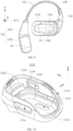
- the present disclosure provides a charging case for two earphones.
- Each of the two earphones may include a core module and a hook structure connected to the core module.
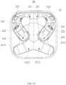
- the charging case may include a lower housing assembly, the lower housing assembly may be disposed with two profiling grooves, each of the two profiling grooves may be configured to accommodate one of the two earphones, and each of the two profiling grooves may include a first profiling groove region corresponding to the core module and a second profiling groove region corresponding to the hook structure.
- the second profiling groove regions of the two profiling grooves may be disposed to intersect with each other, such that when the two profiling grooves accommodate the two earphones, respectively, two hook structures of the two earphones overlap with each other.
- each of the two hook structures may include an elastic part, and the two second profiling groove regions may be disposed to cause the two elastic parts of the two earphones to overlap with each other.
- each of the two elastic parts when viewing directly above the charging case, may have an arc shape.
- two overlapping points may be formed, and the two profiling grooves may be mirror symmetrical with a line connecting the two overlapping points as an axis of symmetry.
- regions of the two second profiling groove regions located between the two overlapping points may integrate with each other.
- the hook structure may include a rigid part disposed between the elastic part and the core module
- the lower housing assembly may include a limiting structure.
- the limiting structure may apply a pressing force facing a bottom of the profiling groove on the rigid part of the earphone, and at least a portion of the elastic part of the earphone may forms a cantilevered structure with respect to an action point of the limiting structure on the rigid part.
- the limiting structure may be a bump that interferes with the rigid part when the earphone is placed into the corresponding profiling groove and taken out of the corresponding profiling groove.
- a count of the bump may be two, and the two bumps may be disposed on opposing sides of the corresponding profiling groove.
- the rigid part may be clamped into a space between the two bumps under a pressing force applied by a user.
- the lower housing assembly may include a first magnetic suction structure, a second magnetic suction structure, and a first electrode terminal, the first electrode terminal may be disposed between the first magnetic suction structure and the second magnetic suction structure.
- the limiting structure may be a position limiting groove connected with the two profiling grooves, and the hook structure may be further moved into the position limiting groove after the earphone is placed into the corresponding profiling groove.
- the lower housing assembly may include a first magnetic suction structure. After the earphone is placed into the corresponding profiling groove, a first magnetic suction structure of the lower housing assembly and a first magnetic suction member within the earphone may form a first magnetic suction matching pair to guide the hook structure of the earphone to further move into the position limiting groove.
- a bottom of the corresponding profiling groove may be disposed with a guiding surface for guiding the hook structure of the earphone to the position limiting groove.
- the lower housing assembly may include a second magnetic suction structure and a first electrode terminal, the first electrode terminal may be disposed between the first magnetic suction structure and the second magnetic suction structure.
- the second magnetic suction structure and a second magnetic suction member within the earphone may form a second magnetic suction matching pair, and the first magnetic suction matching pair and the second magnetic suction matching pair may cause the first electrode terminal and a second electrode terminal of the earphone in one-to-one contact.
- the first magnetic suction member may be a loudspeaker within the core module, and the second magnetic suction member may be a magnet disposed on the rigid part.
- the charging case may include an upper housing assembly and a shaft mechanism connecting the upper housing assembly and the lower housing assembly.
- the shaft mechanism may include a lower fixing seat integrally molded with the lower housing assembly, an upper fixing seat integrally molded with the upper housing assembly, and a shaft, and the lower fixing seat may extend into the upper housing assembly to be pivotally connected to the upper fixing seat through the shaft.
- the shaft mechanism may further include a reinforcement member connected to the lower fixing seat, and the shaft may be further penetrated through the reinforcement member.
- two upper fixing seats may be spaced apart along an extension direction of the shaft
- the lower fixing seat may be disposed between the two upper fixing seats and be spaced apart from the two upper fixing seats along the extension direction of the shaft.
- the reinforcement member may include a connecting portion connected to the lower fixing seat and two sleeve parts disposed at intervals along the extension direction of the shaft, the two sleeve parts may be disposed in a spacing region between the lower fixing seat and the two upper fixing seats, respectively, and the shaft may be inserted within the lower fixing seat, the two the sleeve portions, and the two upper fixing seats.
- the lower housing assembly may include a lower housing body and a lower housing liner disposed on an inner side of the lower housing body
- the upper housing assembly may include an upper housing body and an upper housing liner disposed on an inner side of the upper housing body.
- the lower fixing seat and the lower housing body may be integrally molded plastic parts
- the upper fixing seats and the upper housing body may be integrally molded plastic parts
- the two profiling grooves may be disposed on the lower housing liner
- the reinforcement member may be a metal part.
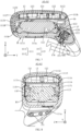
- the charging case may include a main control circuit board and a magnetic guide member disposed within the lower housing assembly, and a permanent magnet disposed within the upper housing assembly.
- the main control circuit board may be disposed with a Hall sensor, the Hall sensor may be disposed adjacent to the magnetic guide member.
- the permanent magnet may magnetize the magnetic guide member to different degrees, and the Hall sensor may sense a magnetic field of the magnetic guide member to detect the open state or the closed state.
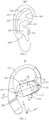
- FIG. 1 is a schematic diagram illustrating an exemplary anterior side profile of an ear of a user according to some embodiments of the present disclosure.
- an ear 100 of a user may include physiological parts, such as an external ear canal 101, a cavity of auricular concha 102, a cymba of auricular concha 103, a triangular fossa 104, an antihelix 105, a scapha 106, a helix 107, and a tragus 108.
- the external ear canal 101 has a certain depth and extends to a tympanic membrane of the ear 100, for the convenience of description and in combination with FIG.
- the external ear canal 101 refers to an entrance (i.e., an aperture) of the external ear canal 101 that is away from the tympanic membrane in the present disclosure.
- the physiological parts e.g., the cavity of auricular concha 102, the cymba of auricular concha 103, the triangular fossa 104, etc.
- the cavity of auricular concha 102 is directly connected to the external ear canal 101, which can be simply regarded as that the aperture is located at a bottom of the cavity of auricular concha 102.
- a simulator e.g., GRAS 45BC KEMAR
- a head and (left and right) ears of the head may be produced based on the ANSI: S3.36, S3.25 and IEC: 60318-7 standards. Therefore, in the present disclosure, embodiments such as "a user wears earphones,” “the earphones are in a wearing state,” “in the wearing state,” etc., may refer to the earphones of the present disclosure being worn on the ears of the simulator. Due to the individual differences between different users, there may be certain differences when the earphones are worn by different users and when the earphones are worn on the ears of the simulator, but the differences should be tolerated.
- sagittal plane refers to a section perpendicular to the ground made along anterior and posterior directions of the human body, which divides the human body into left and right parts.
- coronal plane refers to a section perpendicular to the ground made along left and right directions of the human body, which divides the human body into anterior and posterior parts.
- the horizontal plane refers to a section parallel to the ground made along upper and lower directions of the human body, which divides the human body into upper and lower parts.
- the sagittal axis refers to an axis along an anterior-posterior direction of the human body and perpendicular to the coronal plane
- the coronal axis refers to an axis along a left-right direction of the human body and perpendicular to the sagittal plane
- the perpendicular axis refers to an axis along an upper-lower direction of the human body and perpendicular to the horizontal plane.
- an "anterior side of the ear” of the present disclosure is a concept with respect to a "posterior side of the ear.”
- the anterior side refers to a side of the ear away from the head
- the posterior side refers to a side of the ear facing the head, both of which are directed toward the ear of the user.
- each of at least one earphone 10 may include a core module 11 and a hook structure 12 connected to the core module 11.
- the core module 11 may be disposed on an anterior side of an ear in a wearing state, and at least a portion of the hook structure 12 may be disposed on a posterior side of the ear in the wearing state, so as to dispose the earphone 10 on the ear in the wearing state.
- the core module 11 may include a connection end CE connected to the hook structure 12 and a free end FE not connected to the hook structure 12.
- the core module 11 may be disposed not to block an external ear canal in the wearing state, so that the earphone 10 serves as an "open earphone.” Due to individual differences between different users, when the earphone 10 is worn by different users, the core module 11 may partially block the external ear canal, but the external ear canal may remain unblocked.
- At least a portion of the hook structure 12 may be disposed as a profiling structure that fits with at least one of the posterior side of the ear and the head to increase a contact area between the hook structure 12 and the ear and/or the head, thereby increasing a resistance of the earphone 10 from falling off from the ear.
- at least a portion of the hook structure 12 may be disposed as an elastic structure to have a certain amount of deformation in the wearing state, so as to increase a positive pressure of the hook structure 12 on the ear and/or the head, thereby increasing the resistance of the earphone 10 from falling off from the ear.
- the hook structure 12 may be disposed to abut against the head in the wearing state to form a counterforce that presses on the ear, so as to press the core module 11 on the anterior side of the ear, thereby increasing the resistance of the earphone 10 from falling off from the ear.
- the core module 11 and the hook structure 12 may be disposed to clamp physiological part(s) (e.g., a region where an antihelix is located, a region where a cymba of auricular concha is located, etc.) from the anterior and posterior sides of the ear in the wearing state, thereby increasing the resistance of the earphone 10 from falling off from the ear.
- At least a portion of the core module 11 or an auxiliary structure connected to the core module 11 may be disposed to extend into the physiological part(s) (e.g., the cavity of auricular concha, a cymba of auricular concha, a triangular fossa, a scapha, etc.), thereby increasing the resistance of the earphone 10 from falling off from the ear.
- the physiological part(s) e.g., the cavity of auricular concha, a cymba of auricular concha, a triangular fossa, a scapha, etc.
- the free end FE of the core module 11 may extend into the cavity of auricular concha.
- the core module 11 and the hook structure 12 may be disposed to jointly clamp anterior and posterior sides of an ear region corresponding to the cavity of auricular concha, so as to increase the resistance of the earphone 10 from falling off from the ear, thereby improving the stability of the earphone 10 in the wearing state.
- the free end FE may press into the cavity of auricular concha in a thickness direction X.
- the free end FE may abut against the cavity of auricular concha in a length direction Y and a width direction Z.
- the free end FE of the core module 11 in addition to extending into the concha cavity, can not only be projected orthogonally on the antihelix, but also can be projected orthogonally on left and right sides of the head and be located at a position of the anterior side of the ear on the sagittal axis of the human body.
- the hook structure 12 may support the core module 11 to be worn to wearing positions of the cavity of auricular concha, the antihelix, the anterior side of the ear, etc.
- the core module 11 in the wearing state, may include an inner side surface IS facing the ear along the thickness direction X, an outer side surface OS away from the ear along the thickness direction X, and a connection surface connecting the inner side surface IS and the outer side surface OS.
- the thickness direction X may be defined as a direction in which the core module 11 approaches or moves away from the ear in the wearing state.
- at least a portion of the connection surface may be disposed within the cavity of auricular concha in the wearing state, and form a first contact region with the anterior side of the ear.
- the hook structure 12 may form a second contact region with the posterior side of the ear in the wearing state.
- the second contact region and the first contact region may at least partially overlap along the thickness direction of the ear region.
- a clamping force formed can be mainly manifested as a compressive stress, which improves the stability and comfort of the earphone 10 in the wearing state.
- the core module 11 may be disposed as a shape, such as a circle, an oval, a rounded square, a rounded rectangle, etc.
- the connection surface may refer to a curved side surface of the core module 11.
- the connection surface may include a lower side surface LS, an upper side surface US, and a rear side surface RS as mentioned later.
- the core module 11 may have the length direction Y and the width direction Z perpendicular to the thickness direction X, and the length direction Y and the width direction Z may be orthogonal to each other.
- the length direction Y may be defined as a direction in which the core module 11 approaches or moves away from the back of the user's head in the wearing state
- the width direction Z may be defined as a direction in which the core module 11 approaches or moves away from the top of the user's head in the wearing state. Therefore, for the convenience of description, the core module 11 being disposed as the rounded rectangle may be taken as an example for illustration in the present embodiment.
- a length of the core module 11 along the length direction Y may be greater than a width of the core module 11 along the width direction Z.
- connection end CE in the wearing state and viewed along the direction where the coronal axis of the human body is located, the connection end CE may be closer to the top of the head than the free end FE, so as to facilitate the free end FE to extend into the cavity of auricular concha.
- an included angle between the length direction Y and a direction where the sagittal axis of the human body is located may be within a range of 15 degrees to 60 degrees. If the included angle is too small, the free end FE may be unable to extend into the cavity of auricular concha, and a sound outlet hole 111a on the core module 11 may be too far away from the external ear canal.
- the free end FE may also be unable to extend into the cavity of auricular concha, and the external ear canal may be blocked by the core module 11.
- the included angle by disposing the included angle in such a manner, not only the free end FE can be able to extend into the cavity of auricular concha, but also a suitable distance between the sound outlet hole 111a on the core module 11 and the external ear canal can be disposed, so that sound waves generated by the core module 11 that the user can hear are increased when the external ear canal is not blocked.
- an orthographic projection of the hook structure 12 on a reference plane (e.g., an XZ plane in FIG. 4 ) perpendicular to the length direction Y may partially overlap with an orthographic projection of the free end FE on the same reference plane.
- An overlapping region formed by the orthographic projection of the hook structure 12 on the reference plane and the orthographic projection of the free end FE on the same reference plane may be located between the inner side surface IS and the outer side surface OS in the thickness direction X.
- the core module 11 and the hook structure 12 can jointly clamp the ear from the anterior and posterior sides of the ear, but also the clamping force formed may be mainly manifested as the compressive stress, which improves the stability and comfort of the earphone 10.
- the hook structure 12 may include an elastic metal wire 121 connected to the core module 11 and a battery housing 123 connected to an end of the elastic metal wire 121 away from the core module 11.
- a battery 14 coupled to the core module 11 may be disposed in the battery housing 123.
- An orthographic projection of the battery housing 123 on the reference plane may partially overlap with the orthographic projection of the free end FE on the same reference plane. In this way, when the free end FE abuts against the cavity of auricular concha, the battery housing 123 can support the ear from the posterior side of the ear, which improves the stability of the earphone 10 in the wearing state.
- the battery housing 123 may include a housing cover 1231 connected to the elastic metal wire 121 and a battery compartment 1232 connected to the housing cover 1231. The battery compartment 1232 and the housing cover 1231 may cooperate with each other to form a chamber structure for accommodating the battery 14.
- the core module 11 in the wearing state, may include the upper side surface US away from the external ear canal along the width direction Z, the lower side surface LS facing the external ear canal along the width direction Z, and the rear side surface RS connecting the upper side surface US and the lower side surface.
- the rear side surface RS may be disposed at an end of the length direction Y facing the back of the head in the wearing state, and at least a portion of the rear side surface RS may be disposed within the cavity of auricular concha.
- An edge of an orthographic projection of the hook structure 12 on a reference plane e.g., a YZ plane in FIG.
- an overall degree of curvature of the hook structure 12 in the first section S1 may be greater than an overall degree of curvature of the hook structure 12 in the second section S2. In this way, not only the free end FE can be allowed to extend into the cavity of auricular concha, but also the hook structure 12 can cooperate with the core module 11 to provide a suitable clamping force.
- the above overall degree of curvature may be used to qualitatively characterize a degree of curvature of different sections of the hook structure 12.
- a radius of curvature of each section may be a constant value or be continuously varied. Therefore, there may be at least one point within the first section S1 having a radius of curvature that is less than a radius of curvature of any point within the second section S2.
- the overall degree of curvature may also be quantitatively characterized by an average radius of curvature. That is, radii of curvature of N points on each section may be determined, and then averaged to obtain an average radius of curvature of each section.
- a length of the second section S2 may be greater than a length of the first section S1 in an extension direction of the hook structure 12, so as to facilitate the clamping of the ear by the hook structure 12 together with the core module 11, and to increase a contact area between the hook structure 12 and the user's skin, thereby improving the stability of the earphone 10 in the wearing state.
- the earphone 10 may include a first reference line section RL1 parallel to the width direction Z.
- a starting point of the first reference line section RL1 may be a point where the first reference line section RL1 intersects with the upper side surface US, and an ending point of the first reference line section RL1 may be the demarcation point DP.
- a second reference line section RL2, a third reference line section RL3, and a fourth reference line section RL4 as mentioned later may be sequentially increasingly farther away from the starting point of the first reference line section RL1 in the width direction Z.
- a length of the first reference line section RL1 may be within a range of 13 millimeters (mm) to 20 mm.
- the free end FE may be unable to extend into the cavity of auricular concha, and a sound outlet hole 111a on the core module 11 may be too far away from the external ear canal. If the length of the first reference line section RL1 is too large, the free end FE may also be unable to extend into the cavity of auricular concha, and the external ear canal may be blocked by the core module 11.
- the length of the first reference line section RL1 in such a manner, not only the free end FE can be able to extend into the cavity of auricular concha, but also the suitable distance between the sound outlet hole 111a on the core module 11 and the external ear canal can be disposed, so that sound waves generated by the core module 11 that the user can hear are increased when the external ear canal is not blocked.
- the second reference line section RL2 passing 1/4 of the first reference line section RL1 and parallel to the length direction Y may intersect with the first section S1 and the second section S2 at a first intersection point P1 and a second intersection point P2, respectively.
- a distance between the first intersection point P1 and the starting point of the first reference line section RL1 may be within a range of 9 mm to 15 mm, and a distance between the second intersection point P2 and the starting point of the first reference line section RL1 may be within a range of 12 mm to 19 mm.
- the third reference line section RL3 passing through 1/2 of the first reference line section RL1 and parallel to the length direction Y may intersect with the first section S1 and the second section S2 at a third intersection point P3 and a fourth intersection point P3, respectively.
- a distance between the third intersection point P3 and the starting point of the first reference line section RL1 may be within a range of 11 mm to 18 mm, and a distance between the fourth intersection point P4 and the starting point of the first reference line section RL1 may be within a range of 12 mm to 19 mm.
- the fourth reference line section RL4 passing through 3/4 of the first reference line section RL1 and parallel to the length direction Y may intersect with the first section S1 and the second section S2 at a fifth intersection point P5 and a sixth intersection point P6, respectively.
- a distance between the fifth intersection point P5 and the starting point of the first reference line section RL1 may be within a range of 12 mm to 19 mm
- a distance between the sixth intersection point P6 and the starting point of the first reference line section RL1 may be within a range of 12 mm to 19 mm.
- a fifth reference line section RL5 with a shortest spacing along the length direction Y between the second section S2 and the rear side surface RS.
- a length of the fifth reference line section RL5 may be within a range of 2 mm to 3 mm. If the length of the fifth reference line section RL5 is too small, the clamping force provided by the core module 11 and the hook structure 12 on the ear may be too large, causing wearing discomfort. If the length of the fifth reference line section RL5 is too large, the clamping force provided by the core module 11 and the hook structure 12 on the ear may be too small, causing wearing instability. In other words, by disposing the length of the fifth reference line section RL5 in such a manner, the stability and comfort of the earphone 10 in the wearing state can be considered.
- the fifth reference line section RL5 may be defined by designating a point where the fifth reference line section RL5 intersects with the rear side surface RS as a starting point of the fifth reference line section RL5, and designating a point where the fifth reference line section RL5 intersects with the second section S2 as an ending point of the fifth reference line section RL5.
- An orthographic projection of an intersection point between the first reference line section RL1 and the upper side surface US along the length direction Y may intersect with the second section S2 at a seventh intersection point P7, and an orthographic projection of an intersection point between an extension line of the first reference line section RL1 and the lower side surface LS along the length direction Y may intersect with the second section S2 at an eighth intersection point P8.
- a distance between the seventh intersection point P7 and the starting point of the fifth reference line section RL5 may be within a range of 5 mm to 9 mm, and a distance between the eighth intersection point P8 and the starting point of the fifth reference line section RL5 may be within a range of 5 mm to 9 mm. In this way, the hook structure 12 can be better fit with the ear while the stability and comfort of the earphone 10 in the wearing state can be considered.
- the core module 11 may include a core housing 111 connected to the hook structure 12 and a loudspeaker 112 disposed within the core housing 111.
- An inner side surface (e.g., the inner side surface IS) of the core housing 111 facing the ear in the wearing state may be disposed with the sound outlet hole 111a, and the sound waves generated by the loudspeaker 112 may be propagated out through the sound outlet hole 111a, so as to be easily transmitted into the external ear canal.
- the sound outlet hole 111a may also be disposed on a side of the core housing 111 corresponding to the lower side surface LS, and may also be disposed at a corner between the inner side surface and the lower side surface LS.
- the loudspeaker 112 may include a magnetic circuit system, a voice coil extending into the magnetic circuit system, and a diaphragm connected to the voice coil. A magnetic field generated by the voice coil after being energized may interact with a magnetic field formed by the magnetic circuit system to drive the diaphragm to generate mechanical vibrations, and then a sound may be generated by propagating the mechanical vibrations through media, such as air, etc.
- the earphone 10 may include a main control circuit board 13 disposed within the core housing 111 and the battery 14 disposed at one end of the hook structure 12 away from the core module 11.
- the battery 14 and the loudspeaker 112 may be coupled to the main control circuit board 13, respectively, to allow the battery 14 to power the loudspeaker 112 under the control of the main control circuit board 13.
- both the battery 14 and the loudspeaker 112 may also be disposed within the core housing 111, and the battery 14 may be located closer to the connection end CE while the loudspeaker 112 may be located closer to the free end FE.
- the core module 11 may cooperate with the cavity of auricular concha in the wearing state to form an auxiliary chamber that is connected to the external ear canal, and at least a portion of the sound outlet hole 111a may be located within the auxiliary chamber. In this way, in the wearing state, the sound waves generated by the loudspeaker 112 and propagated through the sound outlet hole 111a may be limited by the auxiliary chamber.
- the auxiliary chamber can aggregate the sound waves so that more of the sound waves can be propagated into the external ear canal, which increases the volume and sound quality of the sound heard by the user in a near field, thereby improving the acoustic effectiveness of the earphone 10.
- the auxiliary chamber since the core module 11 can be disposed not to block the external ear canal in the wearing state, the auxiliary chamber may be disposed in a semi-open arrangement.
- the core module 11 is generally disposed with an acoustic hole (e.g., a pressure relief hole 111c as mentioned later), and sound waves propagated through the acoustic hole generally form a second sound leakage in the far field.
- a phase of the first sound leakage and a phase of the second sound leakage are (proximity) opposite to each other, so that the two sound leakages can be canceled out in the far field inversely, thereby reducing the sound leakage of the earphone 10 in the far field.
- the earphone 10 may include an adjusting mechanism connecting the core module 11 and the hook structure 12.
- Different users can adjust a relative position of the core module 11 on the ear in the wearing state through the adjusting mechanism, so as to cause the core module 11 to be located at a suitable position, thereby causing the core module 11 to form the auxiliary chamber with the cavity of auricular concha.
- the adjusting mechanism due to the presence of the adjusting mechanism, the user can adjust the earphone 10 to be worn in a more stable and comfortable position.
- the earphone 10 was first worn on the simulator, a position of the core module 11 was adjusted on an ear of the simulator, and then a frequency response curve of the earphone 10 was measured by a detector (e.g., a microphone) disposed within an external ear canal (e.g., a position of a tympanic membrane, i.e., a listening position) of the simulator, so as to simulate a listening effectiveness of the user after wearing the earphone 10.
- the frequency response curve may be used to characterize a changing relationship between a vibration magnitude and a frequency.
- a horizontal coordinate of the frequency response curve may be denoted as a frequency in hertz (Hz), and a vertical coordinate of the frequency response curve may be denoted as a vibration magnitude in decibels (dB).
- a curve 6_1 may represent a frequency response curve when the core module 11 is in the wearing state without forming the auxiliary chamber with the cavity of auricular concha
- a curve 6_2 may represent a frequency response curve when the core module 11 is in the wearing state with forming the auxiliary chamber with the cavity of auricular concha. Based on this, it can be directly and unquestionably concluded from a comparison diagram of the frequency response curves shown in FIG. 6 that the curve 6_2 is located overall above the curve 6_1.
- the core module 11 forming the auxiliary chamber with the cavity of auricular concha in the wearing state can improve the acoustic effectiveness of the earphone 10.
- the core module 11 may include a flexible insert 1131 disposed outside the core housing 111.
- a hardness of the flexible insert 1131 may be smaller than a hardness of the core housing 111.
- the core housing 111 may be a plastic component.
- the flexible insert 1131 may be made of silicone, rubber, etc., and may be formed on a predetermined region of the core housing 111 by injection molding. In some embodiments, at least a portion of the flexible insert 1131 may cover a region of the core housing 111 corresponding to the free end FE, such that at least a portion of the core module 11 abuts against the cavity of auricular concha through the flexible insert 1131.
- the portion of the core housing 111 that extends into the cavity of auricular concha and is in contact with the cavity of auricular concha may be covered by the flexible insert 1131.
- the flexible insert 1131 may serve as a cushioning effect between the core housing 111 and the ear (e.g., the ear region) to relieve a pressure of the earphone 10 on the ear, thereby improving the comfort of the earphone 10 in the wearing state.
- the flexible insert 1131 may successively cover at least a portion of regions of the core housing 111 corresponding to the rear side surface RS, the upper side surface US, and the lower side surface LS.
- a region of the core housing 111 corresponding to the rear side surface RS may be covered more than 90% by the flexible insert 1131, and regions of the core housing 111 corresponding to the upper side surface US and the lower side surface LS may be respectively covered about 30% by the flexible insert 1131. In this way, the comfort of the earphone 10 in the wearing state and the need for structural components such as the loudspeaker 112 disposed in the core housing 111 may be considered.
- the flexible insert 1131 may have a U-shape viewed along the thickness direction X.
- a portion of the flexible insert 1131 corresponding to the lower side surface LS may abut against the tragus.
- a thickness of a portion of the flexible insert 1131 corresponding to the rear side surface RS may be smaller than a thickness of a portion of the flexible insert 1131 corresponding to the upper side surface US and a thickness of the portion of the flexible insert 1131 corresponding to the lower side surface LS, respectively, which provides good comfort even when the core module 11 abuts against an uneven position within the cavity of auricular concha.
- the core housing 111 may include a core inner housing 1111 and a core outer housing 1112 snap-fit with each other along the thickness direction X.
- the core inner housing 1111 may be closer to the ear than the core outer housing 1112 in the wearing state.
- a parting surface 111b between the core outer housing 1112 and the core inner housing 1111 may be inclined toward a side where the core inner housing 1111 is located in a direction close to the free end FE, which causes the flexible insert 1131 to be disposed in the region of the core housing 111 corresponding to the free end FE as much as possible.
- the whole flexible insert 1131 may be disposed in the region of the core housing 111 corresponding to the free end FE to simplify a structure of the core module 11 and reduce a processing cost.
- the core module 11 may include a flexible coating 1132.
- a hardness of the flexible coating 1132 may be smaller than the hardness of the core housing 111.
- the core housing 111 may be a plastic fabrication.
- the flexible coating 1132 may be made of silicone, rubber, etc., and may be formed on the predetermined region of the core housing 111 by injection molding, glue connection, etc.
- the flexible coating 1132 may integrally cover at least a portion of an outer surface of the flexible insert 1131 and at least a portion of an outer surface of the core outer housing 1112 that is not covered by the flexible insert 1131, which improves the consistency of the core module 11 in appearance.
- the flexible coating 1132 may further cover an outer surface of the core inner housing 1111.
- the hardness of the flexible insert 1131 may be smaller than the hardness of the flexible coating 1132 to allow the flexible insert 1131 to be soft enough.
- the flexible coating 1132 can also improve the comfort of the earphone 10 in the wearing state and have a certain structural strength to protect the flexible insert 1131.
- an area of the outer surface of the flexible insert 1131 may be within a range of 126 square millimeters (mm 2 ) to 189 mm 2 . If the area is too small, the comfort of the core module 11 in the wearing state can be reduced.
- a thickness of the flexible coating 1132 may be smaller than a thickness of the core outer housing 1112.
- the core module 11 may include a metallic function pattern, such as an antenna pattern 1141 and/or a touch pattern 1142 disposed between the core outer housing 1112 and the flexible coating 1132.
- the antenna pattern 1141 may be molded on an outer side of the core outer housing 1112 using a laser-direct-structuring (LDS) technique.
- the touch pattern 1142 may be molded on the outer side of the core outer housing 1112 using the LDS technique, or may be a flexible touch circuit board attached to the outer side of the core outer housing 1112.
- the core outer housing 1112 may be disposed with metalized holes connected to the antenna pattern 1141 and the touch pattern 1142, respectively.
- the main control circuit board 13 since the main control circuit board 13 is disposed in the core housing 111 (e.g., the main control circuit board 13 is connected to the core outer housing 1112), the main control circuit board 13 may be in contact with an inner wall of a corresponding metalized hole through an elastic metal component (e.g., a pogo-PIN, a metal shrapnel, etc.).
- an elastic metal component e.g., a pogo-PIN, a metal shrapnel, etc.
- the antenna pattern 1141 and the touch pattern 1142 may be connected to a pogo-PIN 131 and a pogo-PIN 132 soldered on the main control circuit board 13, respectively.
- the loudspeaker 112 may be disposed on a side of the main control circuit board 13 away from the core outer housing 1112.
- the antenna pattern 1141 may be disposed on the outer side of the core outer housing 1112, which can increase a spacing between the antenna pattern 1141 and the main control circuit board 13. That is, an antenna headroom region can be improved, thereby increasing the interference immunity of the antenna pattern 1141.
- an external signal trigger source e.g., a user's finger
- a touch spacing can be reduced, thereby increasing the sensitivity of the touch pattern 1142 to be triggered by the user.
- the antenna pattern 1141 may surround a periphery of the touch pattern 1142 to make full use of a space of the outer side of the core outer housing 1112.
- the antenna pattern 1141 may have a U-shape, and the touch pattern 1142 may have a square shape.
- the core module 11 may include a microphone 133 soldered on the main control circuit board 13.
- the microphone 133 may pick up a user voice and environment sound through a sound pickup through hole disposed in the core outer housing 1112.
- the main control circuit board 13 When the main control circuit board 13 is connected to the core outer housing 1112, the microphone 133 may be further pressed against the core outer housing 1112.
- the core inner housing 1111 may include a bottom wall 1113 and a first side wall 1114 connected to the bottom wall 1113
- the core outer housing 1112 may include a top wall 1115 and a second side wall 1116 connected to the top wall 1115.
- the second side wall 1116 and the first side wall 1114 may be snap-fit to each other along the parting surface 111b, and may support each other. Viewed along the width direction Z and in a reference direction (e.g., an opposite direction of an arrow Y in FIGs.
- a portion of the first side wall 1114 near the free end FE may be progressively closer to the bottom wall 1113 in the thickness direction X, and a portion of the second side wall 1116 near the free end FE may be progressively farther away from the top wall 1115 in the thickness direction X, such that the parting surface 111b is inclined toward the side where the core inner housing 1111 is located in the direction close to the free end FE.
- at least a portion of the flexible insert 1131 may be disposed on an outer side of the second side wall 1116.
- a portion of the flexible insert 1131 may be disposed on an outer side of the top wall 1115 in addition to being disposed on the outer side of the second side wall 1116.
- the sound outlet hole 111a may be disposed on the bottom wall 1113.
- the sound outlet hole 111a may also be disposed on a side of the first side wall 1114 corresponding to the lower side surface LS, and may also be disposed at a corner between the first side wall 1114 and the bottom wall 1113.
- the antenna pattern 1141, the touch pattern 1142, and their respective metalized holes may be disposed on the top wall 1115, and the sound pickup through hole of the microphone 133 may also be disposed on the top wall 1115.
- the core outer housing 1112 may be disposed with an embedding groove at least partially disposed on the second side wall 1116.
- the flexible insert 1131 may be embedded in the embedding groove, resulting in a continuous transition between an outer surface of a region of the core outer housing 1112 that is not covered by the flexible insert 1131 and the outer surface of the flexible insert 1131.
- a region where the flexible insert 1131 is located in FIG. 7 may be simply regarded as the embedding groove.
- the flexible insert 1131 it is not only beneficial for the flexible insert 1131 to be stacked on the core outer housing 1112 during the injection molding to avoid the flexible insert 1131 from overflowing, but is also beneficial to improve the appearance quality of the core module 11 to avoid the core module 11 from having a pitted surface.
- the second side wall 1116 may include a first sub-side wall segment 1117 and a second sub-side wall segment 1118 connected to the first sub-side wall segment 1117.
- the first sub-side wall segment 1117 may be closer to the top wall 1115 in the thickness direction X than the second sub-side wall segment 1118, and the second sub-side wall segment 1118 may protrude toward the outer side of the core housing 111 than the first sub-side wall segment 1117.
- the second side wall 1116 may have a step-like structure.
- the flexible insert 1131 it is not only beneficial for the flexible insert 1131 to be stacked on the core outer housing 1112 during the injection molding to avoid the flexible insert 1131 from overflowing, but is also beneficial for the core module 11 to abut against the cavity of auricular concha through the flexible insert 1131, thereby improving the comfort of the earphone10 in the wearing state.
- the main control circuit board 13 may be connected to the core outer housing 1112 (e.g., fixed to a heat stack connected to the top wall 1115), and may partially overlap with the first sub-side wall segment 1117 in the thickness direction X.
- the loudspeaker 112 may partially overlap with the second sub-side wall segment 1118 in the thickness direction X. In this way, a size of the loudspeaker 112 can be disposed in the core housing 111, thereby enhancing a volume of the sound generated by the earphone 10.
- the core housing 111 may be disposed with the pressure relief hole 111c.
- the pressure relief hole 111c may be configured to connect a space on a side of the loudspeaker 112 facing the main control circuit board 13 and the external environment. That is, air can freely move in and out of the space. In this way, a resistance of the diaphragm of the loudspeaker 112 can be reduced during vibration.
- the pressure relief hole 111c may face the top of the head in the wearing state, which prevents the sound waves propagated through the pressure relief hole 111c from forming a sound leakage (i.e., the second sound leakage) and being heard.
- an aperture of the pressure relief hole 111c may be as large as possible to shift a resonance frequency of the second sound leakage as much as possible towards relatively high frequency bands (e.g., a frequency range larger than 4 kilohertz (kHz)), which further avoids the second sound leakage from being heard.
- relatively high frequency bands e.g., a frequency range larger than 4 kilohertz (kHz)
- the core housing 111 may be disposed with a tuning hole 111d.
- the tuning hole 111d may be used to shift the resonant frequency of the second sound leakage as much as possible towards the relatively high frequency bands (e.g., the frequency range larger than 4 kHz), which further prevents the second sound leakage from being heard.
- An area of the tuning hole 111d may be smaller than an area of the pressure relief hole 111c to allow the space on the side of the loudspeaker 112 facing the main control circuit board 13 to be more connected to the external environment through the pressure relief hole 111c.
- a spacing between the sound outlet hole 111a and the pressure relief hole 111c in the width direction Z may be greater than a spacing between the sound outlet hole 111a and the tuning hole 111d in the width direction Z, so as to avoid sound waves respectively propagating through the sound outlet hole 111a and the pressure relief hole 111c to be canceled out in the near field inversely, thereby increasing the volume of the sound propagated through the sound outlet hole 111a heard by the user.
- the tuning hole 111d may be closer to the connection end CE than the sound outlet hole 111a to increase a spacing between the tuning hole 111d and the sound outlet hole 111a in the length direction Y, so as to avoid the sound waves respectively propagating through the sound outlet hole 111a and the tuning hole 111d to be canceled in the near field inversely, thereby increasing the volume of the sound propagated through the sound outlet hole 111a heard by the user.
- the sound outlet hole 111a, the pressure relief hole 111c, and the tuning hole 111d may be disposed on the core inner housing 1111.
- the sound outlet hole 111a may be disposed on the bottom wall 1113
- the pressure relief hole 111c and the tuning hole 111d may be disposed on the first side wall 1114, respectively.
- the pressure relief hole 111c and the tuning hole 111d may be disposed on opposite sides of the first side wall 1114 along the width direction Z, respectively.
- the sound outlet hole 111a, the pressure relief hole 111c, and the tuning hole 111d are disposed on the core inner housing 1111, the structure of the core outer housing 1112 can be simplified, thereby reducing the processing cost.
- the parting surface 111b may be symmetrically disposed with respect to a reference plane perpendicular to the width direction Z, thereby improving the appearance quality of the core module 11.
- the core module 11 may include a bracket 115 disposed within the core housing 111.
- the bracket 115 and the loudspeaker 112 may be surrounded to form an acoustic chamber 116 to separate the acoustic chamber 116 from other structures (e.g., the main control circuit board 13, etc.) within the core housing 111, thereby improving the acoustic performance of the core module 11.
- the core housing 111 may be disposed with an acoustic hole.
- the acoustic hole may include at least one of the pressure relief hole 111c or the tuning hole 111d.
- the bracket 115 may be disposed with an acoustic channel 1151 connecting the acoustic hole and the acoustic chamber 116, so as to allow the acoustic chamber 116 to be connected to the external environment. That is, air can freely move in and out of the acoustic chamber 116. In this way, the resistance of the diaphragm of the loudspeaker 112 can be reduced during vibration.
- the bracket 115 may cooperate with the core housing 111 to form a first glue accommodation groove 1171 surrounding at least a portion of the acoustic hole.
- the first glue accommodation groove 1171 may accommodate first glue for sealing an assembly gap between the bracket 115 and the core housing 111. That is, the first glue may be used for waterproof sealing, which avoids external liquid drop (e.g., sweat, rain, etc.) from intruding into a space where the main control circuit board 13 is located in the movement housing 111.
- the waterproof sealing through the first glue in the present disclosure may eliminate the silicone sleeve in the related technique, which shortens a length of a connection portion (including the acoustic channel 1151 and the acoustic hole) between the acoustic chamber 116 and the external environment, so as to shift the resonant frequency of the sound leakage (i.e., the second sound leakage) propagated out through the pressure relief hole 111c as much as possible towards the relatively high frequency bands (e.g., the frequency range larger than 4 kHz), which further avoids the second sound leakage from being heard.
- the relatively high frequency bands e.g., the frequency range larger than 4 kHz
- the first glue accommodation groove 1171 may surround at least a portion of the pressure relief hole 111c.
- the first glue accommodation groove 1171 may surround at least a portion of the tuning hole 111d.
- the first glue accommodation groove 1171 may surround at least a portion of the pressure relief hole 111c and the tuning hole 111d, respectively.
- the acoustic hole including the pressure relief hole 111c and the sound tuning hole 111d, and the first glue accommodation groove 1171 respectively surrounding at least a portion of the pressure relief hole 111c and tuning hole 111d are taken as an example in the present disclosure.
- the first glue accommodation groove 1171 may surround the whole acoustic hole. That is, the first glue accommodation groove 1171 may be an integrally ring-shaped structure.
- the bracket 115 may include an annular body part 1152 and a docking part 1153 connected to the annular body part 1152.
- the annular body part 1152 may be sleeved on the periphery of the loudspeaker 112 to form the acoustic chamber 116.
- the acoustic channel 1151 may penetrate through the docking part 1153 and the annular body part 1152.
- the docking part 1153 may be disposed between the annular body part 1152 and the core housing 111, and surround at least a portion of the acoustic hole. The docking part 1153 may cooperate with the core housing 111 to form the first glue accommodation groove 1171.
- the acoustic hole may include the pressure relief hole 111c and the tuning hole 111d
- two docking parts 1153 may be accordingly disposed, and two first glue-holding grooves 1171 may be accordingly disposed.
- the docking part 1153 may cooperate with the first side wall 1114 to form the first glue-holding groove 1171.
- the bracket 115 has an annular shape, a side of the loudspeaker 112 facing the main control circuit board 13 may be exposed, which reduces the thickness of the core module 11 in the thickness direction X.
- an inner side of the core housing 111 may be disposed with a depression region 1119.
- the acoustic hole may be disposed on a bottom of the depression region 1119.
- the core module 11 may include a sound barrier mesh 118 disposed within the depression region 1119.
- the docking part 1153 may press the sound barrier mesh 118 on the bottom of the depression region 1119.
- the sound barrier mesh 118 may be pre-fixed to the bottom of the depression region 1119 through double-sided tape or glue.
- the sound barrier mesh 118 may be pre-fixed to a protective steel mesh, and then the protective steel mesh may be pre-fixed to the bottom of the depression region 1119 through the double-sided tape or glue.
- the acoustic hole may include the pressure relief hole 111c and the tuning hole 111d, two depression regions 1119 may be accordingly disposed, and two sound barrier meshes 118 may be accordingly disposed.
- the first glue may be further used to seal the assembly gap between the bracket 115 and the sound barrier mesh 118 and/or the assembly gap between the sound barrier mesh 118 and the core housing 111 (e.g., a side wall of the depression region 1119), thereby further improving waterproof sealing.
- the docking part 1153 may be used to form a bottom wall and a side groove wall of the first glue accommodation groove 1171, and the core housing 111 may be used to form another side groove wall of the first glue-holding groove 1171.
- the side groove wall on the core housing 111 may be disposed opposite to the side groove wall on the docking part 1153, so that the first glue accommodation groove 1171 has a certain width and depth.
- the docking part 1153 may be used to form the side groove wall of the first glue accommodation groove 1171, and the core housing 111 may be used to form the bottom wall and another side groove wall of the first glue accommodation groove 1171.
- the docking part 1153 may be used to form the side groove wall and a portion of the bottom wall of the first glue accommodation groove 1171, and the core housing 111 may be used to form another side groove wall and another portion of the bottom wall of the first glue accommodation groove 1171.
- the loudspeaker 112 may include a body 1121 and an annular bearing platform 1122 disposed along a circumferential direction of the body 1121.
- a lower end of the bracket 115 may be supported on the annular bearing platform 1122.
- a side of the acoustic channel 1151 facing the annular bearing platform 1122 may be openly disposed, and the annular bearing platform 1122 may further seal the open portion of the acoustic channel 1151.
- the first glue accommodation groove 1171 may be simply regarded as surrounding a portion of the acoustic hole, so as to facilitate subsequent filling of the first glue accommodation groove 1171 with glue through, for example, a dispensing operation.
- the annular bearing platform 1122 may include a first annular platform surface 1123 and a second annular platform surface 1124 disposed in a stepped manner.
- the second annular platform surface 1124 may be disposed around a periphery of the first annular platform surface 1123.
- a portion of the lower end of the bracket 115 may be supported on the first annular platform surface 1123, and another portion of the lower end of the bracket 115 may form a spacing region with the second annular platform surface 1124, so that the bracket 115, the annular bearing platform 1122, and the core housing 111 may cooperate with each other to form a second glue accommodation groove 1172.
- the second glue accommodation groove 1172 may accommodate second glue used for sealing assembly gaps between any two of the bracket 115, the annular bearing table 1122, and the core housing 111, thereby performing corresponding waterproof sealing.
- an upper end of the bracket 115 may be lapped on the body 1121, and cooperate with the body 1121 to form a third glue accommodation groove 1173.
- the third glue accommodation groove 1173 may accommodate third glue used for sealing an assembly gap between the bracket 115 and the body 1121, thereby performing corresponding waterproof sealing.
- a specific assembly process of the core module 11 may include following processing operations, and a sequence of the processing operations may be adjusted as needed.
- the sound barrier mesh 118 may be pre-fixed to the bottom of the depression region 1119 through the double-sided tape.
- the loudspeaker 112 may be fixed to the bottom wall 1113, and glue may be dispensed into an assembly gap between the loudspeaker 112 and the bottom wall 1113. A portion of the corresponding glue may be stacked on the second annular platform surface 1124 of the loudspeaker 112.
- the bracket 115 may be fixed to the loudspeaker 112.
- the lower end of the bracket 115 may be supported on the first annular platform surface 1123 of the loudspeaker 112, so that a region between the lower end of the bracket 115 and the second annular platform surface 1124 is also filled with the glue.
- the docking part 1153 of the bracket 115 may be pressed on the sound barrier mesh 118 and cooperate with the first side wall 1114 to form the first glue accommodation groove 1171.
- the upper end of the bracket 115 may be lapped on the body 1121 and cooperate with the body 1121 to form the third glue accommodation groove 1173.
- the first glue accommodation groove 1171, the third glue accommodation groove 1173, the assembly gap between the lower end of the bracket 115 and the loudspeaker 112, and the assembly gap between the lower end of the bracket 115 and the core inner housing 1111 may be dispensed with the glue. Since the assembly gap between the lower end of the bracket 115 and the loudspeaker 112 and the assembly gap between the lower end of the bracket 115 and the core inner housing 1111 are close to the first glue accommodation groove 1171, the assembly gap between the lower end of the bracket 115 and the loudspeaker 112 and the assembly gap between the lower end of the bracket 115 and the core inner housing 1111 may be simply regarded as continuations of the first glue accommodation groove 1171. That is, the first glue accommodation groove 1171 and the second glue accommodation groove 1172 may be connected.
- the hook structure 12 may include an adapter housing 122 connected to the core module 11.
- the adapter housing 122 may be pre-disposed with an accommodation chamber 124, and the earphone10 may include an electronic component 15 that is subsequently installed in the accommodation chamber 124.
- the connection between the adapter housing 122 and the core module 11 may include a snap-fit connection, a soldered connection, a glued connection, a threaded connection, a screw connection, or the like, or any combination thereof.
- the electronic component 15 is installed in the accommodation chamber 124 pre-disposed in the hook structure 12 in the present disclosure, which saves the space of the core module 11 to make the core module 11 more compact and smaller in structure.
- the structure of the core module 11 can be simplified, and relative positions of various structural components in the earphone 10 can be reasonably arranged, which can improve the utilization of the core module 11 and the hook structure 12.
- the adapter housing 122 pre-disposed with the accommodation chamber 124 refers to that the accommodation chamber 124 is formed at the same time as the adapter housing 122 is molded, rather than being processed and formed after the adapter housing 122 is molded.
- the adapter housing 122 may be a plastic housing, and the corresponding accommodation chamber 124 may be obtained after the plastic housing is injection molded by disposing a corresponding mold core.
- the subsequent installation of the electronic component 15 in the accommodation chamber 124 refers to that the electronic component 15 and the adapter housing 122 are not integrally molded structural members.
- the adapter housing 122 may be a plastic housing, and the electronic component 15 may not be integrally injection molded into the plastic housing by way of an insert.
- the accommodation chamber 124 may also be obtained through a drilling operation after the adapter housing 122 has been molded, and the through hole 1251, the blind hole 1252, the through hole 1253, etc., may also be obtained through the drilling operation after the adapter housing 122 has been molded.
- the electronic component 15 may be coupled to the main control circuit board 13, so that the hook structure 12 can be electrically connected to the core module 11.
- the adapter housing 122 may be plugged and fixed with the core housing 111 to realize a structural connection between the hook structure 12 and the core module 11, which is simple and reliable.
- the plugging and fixing refers to that a portion of one of the adapter housing 122 and the core housing 111 is first inserted into the other along an assembly direction, and then plugged and fixed with the help of other limitation structures such as pins.
- An assembly direction of the limitation structure may not be parallel to the assembly direction.
- the plugging and fixing also refers to that one of the adapter housing 122 and the core housing 111 can be plugged and fixed without the aid of the limitation structure when a portion of one of the adapter housing 122 and the core housing 111 is extended into the other.
- the adapter housing 122 may be disposed with a first snap structure 1221, and the core housing 111 may be disposed with a second snap structure 1222.
- the first snap structure 1221 may extend into the core housing 111, and snap with the second snap structure 1222, so that the adapter housing 122 and the core housing 111 are snap-fixed.
- the first snap structure 1221 and the second snap structure 1222 may be directly plugged and fixed without the aid of other restriction structures, which is simple and reliable.
- two first snap structures 1221 may be integrally disposed on the adapter housing 122, and may be spaced apart in the thickness direction X.
- Two second snap structures 1222 may be integrally disposed on the core inner housing 1111, and may be disposed in one-to-one correspondence with the two first snap structures 1221.
- the earphone10 may include a flexible circuit board 16.
- a portion of the flexible circuit board 16 may be disposed within the accommodation chamber 124 to be connected to the electronic component 15 and extend into the core housing 111, which in turn allows the electronic components 15 to be connected to the main control circuit board 13 through the flexible circuit board 16.
- the electronic component 15 may be soldered to one end of the flexible circuit board 16 through surface mounted technology (SMT), and another end of a circuit board of the flexible circuit board 16 and the main control circuit board 13 may be snapped through a board to board (BTB) connector.
- the loudspeaker 112 may be disposed to be connected to the flexible circuit board 16 in an extension path of the flexible circuit board 16.
- leads of the loudspeaker 112 may be soldered to a corresponding region of the flexible circuit board 16. Therefore, the loudspeaker 112 may also be connected to the main control circuit board 13 through the flexible circuit board 16, so that the leads of the loudspeaker 112 do not need to be extended to connect to the main control circuit board 13, which simplifies an alignment structure of the earphone 10, reducing the production cost.
- the adapter housing 122 may be pre-disposed with the through hole 1251 in communication with the accommodation chamber 124.
- the electronic component 15 may include an electrode terminal 151 (also referred to as a second electrode terminal). At least a portion of the electrode terminal 151 may be disposed within the through hole 1251, and the electrode terminal 151 may include a retractable elastic component (e.g., a pogo-PIN) or a non-retractable rigid component (e.g., a metal pillar).
- An aperture of the through hole 1251 may be larger than an outer diameter of the electrode terminal 151 to facilitate subsequent installation of the electrode terminal 151.
- the electrode terminal 151 may also be integrally molded with the adapter housing 122 in the form of an insert. In some embodiments, the electrode terminal 151 may face the ear in the wearing state. Therefore, by making the electrode terminal 151 invisible in the wearing state, the appearance quality of the earphone 10 in the wearing state can be improved.
- an extension direction of the electrode terminal 151 may be a direction where the electrode terminal 151 retracts.
- the extension direction may be a direction where an axis of the electrode terminal 151 is located.
- multiple electrode terminals 151 may be disposed according to actual use requirements, such as for charging, detecting, etc.
- the electrode terminal 151 may include a charging positive terminal 1511 and a charging negative terminal 1512 spaced apart from each other.
- the charging positive terminal 1511 and the charging negative terminal 1512 may be disposed within corresponding through holes 1251, respectively, so as to facilitate the charging of the earphone 10 through the electrode terminal 151.
- only one of the charging positive terminal 1511 and the charging negative terminal 1512 may also be disposed on the adapter housing 122, and the other may be disposed on another housing in the hook structure 12 (e.g., the battery housing 123) or disposed on the core inner housing 1111.
- the electrode terminal 151 may include a detection terminal 1513 spaced apart from the charging positive terminal 1511 and the charging negative terminal 1512.
- the detection terminal 1513 may be used to perform detection functions, such as a charging detection, a detection of putting the earphone 10 into or out of the charging case, etc.
- the detection terminal 1513 may also be replaced by an electronic component, such as a Hall sensor.
- lines connecting each two of the charging positive terminal 1511, the charging negative terminal 1512, and the detecting terminal 1513 may form a triangle, such as a positive triangle.
- the charging positive terminal 1511, the charging negative terminal 1512, and the detection terminal 1513 may be spaced apart from each other to arrange in a line section, such as a straight line section.
- a spacing between the charging positive terminal 1511 and the charging negative terminal 1512 may be larger than a spacing between the charging negative terminal 1512 and the detection terminal 1513.
- the charging negative terminal 1512 may be disposed between the charging positive terminal 1511 and the detection terminal 1513, and the spacing between the charging positive terminal 1511 and the charging negative terminal 1512 may be larger than the spacing between the charging negative terminal 1512 and the detection terminal 1513.
- the detection terminal 1513 may be disposed between the charging positive terminal 1511 and the charging negative terminal 1512.
- the spacing between the charging positive terminal 1511 and the charging negative terminal 1512 can be increased as much as possible to avoid short circuits between the charging positive terminal 1511 and the charging negative terminal 1512.
- an outer side of the adapter housing 122 may be disposed with a boss 126.
- the through hole 1251 may further penetrate through the boss 126, so that the multiple electrode terminals 151 are exposed at the boss 126, respectively.
- a localization of the adapter housing 122 that is not flat due to having a certain curvature can be made flat through the boss 126 to facilitate the dispose of the electrode terminals 151.
- the charging positive terminal 1511, the charging negative terminal 1512, and the detecting terminal 1513 may be sequentially disposed at intervals along the a length direction of the boss 126.
- the hook structure 12 may include a magnet 127.
- the magnet 127 and the electrode terminal 151 may be exposed on a same side of the adapter housing 122. That is, the magnet 127 and the electrode terminal 151 may be visible on the same side of the adapter housing 122 to make the magnet 127 closer to the outside world where an exposed end of the electrode terminal 151 faces, thereby shortening a spacing between the magnet 127 and a magnetic suction structure used to cooperate with the magnet 127 in a charging device (e.g., the charging case), or a spacing between the magnet 127 and the Hall sensor used to cooperate with the magnet 127, which improves the reliability of functions, such as charging, detection, etc.
- a charging device e.g., the charging case
- the magnet 127 and the electrode terminal 151 may be disposed adjacent to each other to allow the magnet 127 to cooperate with the magnetic suction structure in the charging device (e.g., the charging case), such that the electrode terminal 151 cooperates with an electrode terminal in the charging device to facilitate charging.
- the boss 126 may protrude out of the adapter housing 122 around the magnet 127. That is, the magnet 127 may be lower than the boss 126, so that the electrode terminal 151 is in contact with the electrode terminal in the charging device (e.g., the charging case).
- the magnet 127 may be disposed adjacent to the electrode terminal 151.
- the electrode terminal in the charging device used to cooperate with the electrode terminal 151 may be disposed adjacent to the Hall sensor, which reduces an area of the charging device (e.g., the charging case) used for carrying the electrode terminal and the Hall sensor.
- the hook structure 12 may include a flexible coating 128.
- a hardness of the flexible coating 128 may be smaller than a hardness of the adapter housing 122.
- the adapter housing 122 may be a plastic fabrication.
- the flexible coating 128 may be made of silicone, rubber, etc., and may be formed on the adapter housing 122 by injection molding, glue connection, etc.
- the flexible coating 128 may cover the adapter housing 122 and the magnet 127, such that the magnet 127 is not exposed and the electrode terminal 151 is exposed. That is, the magnet 127 may be invisible and the electrode terminal 151 may be visible.
- the flexible coating 128 can be used to improve the comfort of the earphone 10 in the wearing state.
- a thickness of the flexible coating 128 may be smaller than a thickness of the adapter housing 122.
- the adapter housing 122 may be pre-disposed with the blind hole 1252.
- the blind hole 1252 may not be connected to the accommodation chamber 124 to increase the waterproof and dustproof performance of the accommodation chamber 124.
- the magnet 127 may be disposed at least within the blind hole 1252, and exposed through an open end of the blind hole 1252. In this way, not only the thickness of the adapter housing 122 in a region where the magnet 127 is located can be reduced, but also the appearance quality of the earphone 10 in the region where the magnet 127 is located can be improved.
- the blind hole 1252 may also be disposed as a through hole.
- the multiple electrode terminals 151 may be spaced apart from each other in a line section, such as a straight line section or a zigzag segment.
- the magnet 127 may be located on either side of the line section.
- the magnet 127 may intersect with the line section, and at least a portion of the magnet 127 may be located between any two adjacent electrode terminals 151.
- a count of the magnet 127 may be one, and the magnet 127 may be integrally located on one side of the line section.
- the magnet 127 may intersect with the line section, and be integrally located between any two adjacent electrode terminals 151.
- the count of the magnet 127 may be two. One magnet 127 may be integrally located on one side of the line section, and the other magnet 127 may be integrally located on the other side of the line section. As still another example, the count of the magnet 127 may be one. A portion of the magnet 127 may intersect with the line section and be located between any two adjacent electrode terminals 151, and another portion may be located below the electrode terminal 151 in the extension direction.
- the multiple electrode terminals 151 may include the charging positive terminal 1511, the charging negative terminal 1512, and the detecting terminal 1513 arranged in the straight line section.
- the magnet 127 may be located on one side of the straight line section.
- a center of the magnet 127 may have a first distance, a second distance, and a third distance from centers of the charging positive terminal 1511, the charging negative terminal 1512, and the detection terminal 1513, respectively.
- the third distance may be larger than the first distance and the second distance, respectively, so as to prioritize the charging reliability.
- the hook structure 12 is disposed with the flexible coating 128, in order to conveniently determine a relative position relationship between the magnet 127, the charging positive terminal 1511, the charging negative terminal 1512, and the detection terminal 1513, the flexible coating 128 can be removed first.
- the electronic component 15 may include the electrode terminal 151 and a microphone 152.
- the adapter housing 122 may be pre-disposed with the accommodation chamber 124, the through hole 1251, and the through hole 1253.
- the through hole 1251 and the through hole 1253 may be in communication with the accommodation chamber 124, respectively. Due to different roles of the electrode terminal 151 and the microphone 152, the through hole 1251 and the through hole 1253 may be disposed on different side walls of the adapter housing 122. Based on this, at least a portion of the electrode terminal 151 may be disposed within the through hole 1251.
- the microphone 152 may be disposed within the accommodation chamber 124 and pick up sounds (e.g., user voice, environmental sounds) outside the earphone 10 through the through hole 1253. In this way, by reasonably arranging a relative position between the electrode terminal 151 and the microphone 152, a space of the accommodation chamber 124 can be fully used, thereby causing the structure of the earphone 10 to be more compact and smaller.
- the earphone10 may include a support assembly 17. At least a portion of the support assembly 17 disposed within the accommodation chamber 124. The support assembly 17 may support and fix the electrode terminal 151 and the microphone 152 on the side walls corresponding to the through hole 1251 and the through hole 1253, respectively. In this way, the electrode terminal 151 and the microphone 152 can be prevented from separating from the adapter housing 122.
- the waterproof and dustproof performance of the electronic component 15 can be improved, and the structure can be simple and reliable.
- the flexible circuit board 16 may include a first circuit board part 161, a second circuit board part 162, and a third circuit board part 163 of an integrated structure.
- the electrode terminal 151 may be soldered on the first circuit board part 161, the second circuit board part 162 may be bent with respect to the first circuit board part 161, and the microphone 152 may be soldered to the third circuit board part 163 and bent with respect to the second circuit board part 162.
- the first circuit board part 161, the second circuit board part 162, and the third circuit board part 163 may correspond to three sides of a six-sided structure, and each two of the three sides may be adjacent.
- An end of the second circuit board part 162 away from the third circuit board part 163 may be connected to the first circuit board part 161, and other portions of the second circuit board part 162 may not be connected to the first circuit board part 161.
- an operator can be allowed to first press the end of the second circuit board part 162 connected to the first circuit board part 161, so that the second circuit board part 162 can flush with the first circuit board part 161 as much as possible to avoid the support assembly 17 subsequently assembled.
- the adapter housing 122 may include two housings whose parting surfaces are perpendicular to the extension direction of the electrode terminal 151.
- the two housings may be snapped with each other to form the accommodation chamber 124.
- the support assembly 17 may be integrally molded with one of the two housings, so as to support (or press) the electrode terminal 151 and the microphone 152, respectively, when the two housings are snapped together.
- at least one of a first support member for supporting the electrode terminal 151 and a second support member for supporting the microphone 152 in the support assembly 17 may be independent of the adapter housing 122, so as to support (or press) the electrode terminal 151 and the microphone 152, respectively, when the two housings are snapped together.
- the support assembly 17 may be assembled to support (or press) the electrode terminal 151 and microphone 152, respectively.
- At least a portion of the adapter housing 122 corresponding to the accommodation chamber 124 may be an integral housing structure. At least one of the first support member for supporting the electrode terminal 151 and the second support member of the support assembly 17 for supporting the microphone 152 in the support assembly 17 may be independent of the adapter housing 122 to at least facilitate the assembly of the electrode terminal 151.
- the support assembly 17 may be independent of the adapter housing 122, and inserted into the accommodation chamber 124. In this way, since the support assembly 17, the electrode terminal 151, and the microphone 152 are independent of the adapter housing 122, the support assembly 17, the electrode terminal 151, and the microphone 152 may be assembled according to a certain sequence, which avoids unnecessary interference in structure, thereby improving the assembly efficiency.
- the first support member for supporting the electrode terminal 151 and the second support member for supporting the microphone 152 in the support assembly 17 may be independent of the adapter housing 122, respectively. That is, the first support member and the second support member may be independent of each other to support (or press) the electrode terminal 151 and the microphone 152, respectively. Therefore, the first support member and the second support member in the support assembly 17 can be designed differently according to actual needs.
- the support assembly 17 may be an integrally molded structural member. That is, the first support member for supporting the electrode terminal 151 and the second support member for supporting the microphone 152 in the support assembly 17 may be connected to each other, which simplifies the structure of the support assembly 17, and avoids the first support member and the second support member being too small and difficult to assemble.
- the support assembly 17 may be fixed in a tight fit with a chamber wall of the accommodation chamber 124 after the support assembly 17 is inserted into place. That is, a process of insertion or extraction of the support assembly 17 may have a certain degree of damping, and the structure may be simple and reliable.
- the chamber wall of the accommodation chamber 124 may be disposed with a guiding groove and a limitation groove which are fit with the support assembly 17.
- the support assembly 17 may be further in a glue connection to the chamber wall of the accommodation chamber 124 through the dispensing operation.
- dimensions of at least a portion of the support assembly 17 and the accommodation chamber 124 in at least one reference direction perpendicular to an insertion direction (e.g., a direction indicated by arrows in FIGs. 17 and 18 ) of the support assembly 17 with respect to the accommodation chamber 124 may be disposed to progressively reduce along the insertion direction, so that the support assembly 17 inserts into an interval region between the electrode terminal 151 and the microphone 152.
- the dimension of at least a portion of the support assembly 17 in the at least one reference direction perpendicular to the insertion direction may be disposed to progressively reduce along the insertion direction
- the dimension of at least a portion of the accommodation chamber 124 in the same reference direction may be disposed to progressively reduce along the insertion direction.
- Trends of reduction of the support assembly 17 and the accommodation chamber 124 may be the same or similar, which facilitates the support assembly 17 to be tightly fitted and fixed with the chamber wall of the accommodation chamber 124 after being inserted in place.
- the chamber wall of the accommodation chamber 124 may include a first chamber wall 1241, a second chamber wall 1242, and a third chamber wall 1243.
- the first chamber wall 1241 and the second chamber wall 1242 may be disposed side by side with each other and spaced apart, and the third chamber wall 1243 may be used to connect the first chamber wall 1241 and the second chamber wall 1242.
- the through hole 1251 may be disposed on the first chamber wall 1241, and the through hole 1253 may be disposed on the third chamber wall 1243.
- the support assembly 17 may include a bottom plate 171 and a first side plate 172 connected to the bottom plate 171.
- the support assembly 17 may have an L-shaped structure.
- a main surface on one side of the bottom plate 171 may be disposed opposite the first chamber wall 1241, and support the electrode terminal 151.
- a main surface on one side of the first side plate 172 may be disposed opposite the third chamber wall 1243, and support the microphone 152.
- the support assembly 17 can be inserted into the accommodation chamber 124 along the insertion direction. After the support assembly 17 is inserted in place, the support assembly 17 can support the electrode terminal 151 and the microphone 152 through the bottom plate 171 and the first side wall, respectively.
- an orthographic projection of the microphone 152 on the first chamber wall 1241 may cover at least a portion of the electrode terminal 151.
- the microphone 152 may cover a portion of the charging positive terminal 1511, which facilitates the structure to be more compact.
- dimensions of at least a portion of the bottom plate 171 and the accommodation chamber 124 in a first reference direction RD1 that is perpendicular to the insertion direction and parallel to the main surface on the one side of the bottom plate 171 may be disposed to progressively reduce along the insertion direction. That is, one of a front end and a rear end of the bottom plate 171 in the insertion direction or a localization between the front end and the rear end may be disposed along the insertion direction, such that dimensions in the first reference direction RD1 remain unchanged.
- Dimensions of the first side plate 172 and the accommodation chamber 124 in a second reference direction RD2 that is perpendicular to the insertion direction and parallel to the main surface on the one side of the first side plate 172 may be disposed to remain unchanged along the insertion direction.
- dimensions of at least a portion of the first side plate 172 and the accommodation chamber 124 in the second reference direction RD2 that is perpendicular to the insertion direction and parallel to the main surface on the one side of the first side plate 172 may be disposed to progressively reduce along the insertion direction. That is, one of a front end and a rear end of the first side plate 172 in the insertion direction or a localization between the front end and the rear end may be disposed along the insertion direction, such that dimensions in the second reference direction RD2 remain unchanged.
- the dimensions of the bottom plate 171 and the accommodation chamber 124 in the first reference direction RD1 that is perpendicular to the insertion direction and parallel to the main surface on the one side of the bottom plate 171 may be disposed to remain unchanged along the insertion direction.
- the dimensions of at least a portion of the first side plate 172 and the accommodation chamber 124 in the second reference direction RD2 that is perpendicular to the insertion direction and parallel to the main surface on the one side of the first side plate 172 may be disposed to progressively reduce along the insertion direction.
- the dimensions of at least a portion of the first side plate 172 and the accommodation chamber 124 in the second reference direction RD2 that is perpendicular to the insertion direction and parallel to the main surface on the one side of the first side plate 172 may be disposed to progressively reduce along the insertion direction.
- the dimension of the bottom plate 171 in the first reference direction RD1 may be simply regarded as a width of the bottom plate 171
- the dimension of the first side plate 172 in the second reference direction RD2 may be simply regarded as a height of the first side plate 172.
- the support assembly 17 may include a second side plate 173 connected to the bottom plate 171.
- the second side plate 173 and the first side plate 172 may be disposed side by side with each other and spaced apart on a same side of the bottom plate 171.
- the second side plate 173 may abut against the second chamber wall 1242 to provide a support force facing the electrode terminal 151 for the bottom plate 171, which improves the support effectiveness of the support assembly 17 on the electrode terminal 151.
- the second side plate 173 may be disposed between the charging positive terminal 1511 and the charging negative terminal 1512, so that the force on each part of the electrode terminal 151 is uniform, further improving the support effectiveness of the support assembly 17 on the electrode terminal 151.
- the chamber wall of the accommodation chamber 124 may include a fourth chamber wall 1244.
- the fourth chamber wall 1244 may connect the first chamber wall 1241 and the second chamber wall 1242, and be opposite to the third chamber wall 1243.
- the first chamber wall 1241 and the second chamber wall 1242 may be disposed substantially as planar structures parallel to each other, and the third chamber wall 1243 and the fourth chamber wall 1244 may be disposed substantially as curved structures flared out from each other, so as to maximize a volume of the accommodation chamber 124 when a volume of the adapter housing 122 is limited.
- the support assembly 17 may include a third side plate 174 connected to the bottom plate 171.
- the first side plate 172 and the third side plate 174 may be respectively located on edges of two sides of the bottom plate 171 in a direction perpendicular to the insertion direction.
- the second side plate 173 may be located between the first side plate 172 and the third side plate 174.
- the third side plate 174 may abut against the fourth chamber wall 1244 to provide a support force facing the microphone 152 for the first side plate 172, thereby improving the support effectiveness of the support assembly 17 on the microphone 152.
- a height of the second side plate 173 may be larger than the height of the first side plate 172 and a height of the third side plate 174, respectively, so that the second side plate 173 abuts against the second chamber wall 1242, and the third side plate 174 abuts against the fourth chamber wall 1244. Since the second side plate 173 and the third side plate 174 are not in direct contact with either of the electrode terminal 151 and the microphone 152, the second side plate 173 and the third side plate 174 may be used for guiding during the process that the support assembly 17 is inserted into the accommodation chamber 124.
- the support assembly 17 may include a reinforcement 175 connecting the second side plate 173 to the bottom plate 171.
- the reinforcement 175 may be disposed on opposite sides of the second side plate 173 facing the first side plate 172 and the third side plate 174.
- the hook structure 12 may include an elastic metal wire 121, the adapter housing 122, the battery housing 123, and a conductor 129. Two ends of the elastic metal wire 121 and the conductor 129 may be connected to the adapter housing 122 and the battery housing 123, respectively, so that the conductor 129 extends along the elastic metal wire 121 and is threaded within the adapter housing 122 and the battery housing 123. In some embodiments, the conductor 129 may also be threaded within a predetermined threading channel after the elastic metal wire 121 is connected to the adapter housing 122 and the battery housing 123.
- the battery 14 may be disposed within the battery housing 123, and may be connected to the flexible circuit board 16 through the conductor 129, which in turn allows the battery 14 to be connected to the main control circuit board 13 through the flexible circuit board 16, which simplifies the alignment structure of the earphone 10, thereby reducing the production cost.
- components e.g., the electrode terminal 151, the microphone 152, the battery 14, etc.
- the hook structure 12 may be connected to the main control circuit board 13 through the flexible circuit board 16.
- the flexible coating 128 may at least further cover an exposed portion of the elastic metal wire 121 and the conductor 129, and at least a portion of the battery 123, so as to expose the conductor 129, which can improve the appearance quality of the earphone 10.
- the adapter housing 122 may also be a portion of the core housing 111.
- the adapter housing 122 may be integrally molded with the core inner housing 1111.
- a portion of the adapter housing 122 may be integrally molded with the core inner housing 1111, and a remaining portion of the adapter housing 122 may be integrally molded with the core outer housing 1112.
- a portion (e.g., an end of the elastic metal wire 121 away from the battery housing 123, the battery housing 123, etc.) of the hook structure 12 other than the adapter housing 122 may be fixedly connected (e.g., through a plug-in fixation) with the core module 11 having the adapter housing 122 at the adapter housing 122.
- positions of structural components e.g., the electrode terminal 151, the microphone 152, the magnet 127, etc.
- the housing assembly may include a plastic housing, a metallic function pattern, and a silicone coating.
- the metallic function pattern may be disposed on an outer side of the plastic housing, and the silicone coating may be covered on a side of the metallic function pattern back from the plastic housing and a portion of the plastic housing that is not covered by the metallic function pattern by injection molding, glue connection, etc.
- the metallic function pattern can be disposed on the outer side of the plastic housing facing the silicone coating, so as to make the metallic function pattern farther away from the interference of other electronic components in the housing assembly or closer to a signal trigger source outside the housing assembly, thereby increasing the anti-interference and sensitivity of the metallic function pattern.
- a structure of the plastic housing may be the same as or similar to that of the core housing 111 or the core outer housing 1112 of the core housing 111, and a structure of the silicone coating may be the same as or similar to that of the flexible coating 1132, which will not be repeated herein.
- the metallic function pattern may be disposed as the antenna pattern 1141 or the touch pattern 1142.
- the antenna pattern 1141 may be disposed on the outer side of the plastic housing, which may increase a spacing between the antenna pattern 1141 and other electronic components in the plastic housing. That is, the antenna headroom region can be increased, thereby increasing the interference immunity of the antenna pattern 1141.
- an external signal trigger source e.g., the user's finger
- a touch spacing can be reduced, thereby increasing the sensitivity of the touch pattern 1142 to be triggered by the user.
- the metal functional pattern may include the antenna pattern 1141 and the touch pattern 1142.
- the antenna pattern 1141 may surround the periphery of the touch pattern 1142 to make full use of the space of the outer side of the core outer housing 1112.
- the antenna pattern 1141 may have the U-shape, and the touch pattern 1142 may have the square shape.
- a thickness of the silicone coating may be smaller than a thickness of the plastic housing, so as to further increase the interference immunity and sensitivity of the metal functional pattern and reduce the volume of the housing assembly while blocking the silicone coating and protecting the metal functional pattern.
- the housing assembly may serve as the core housing that accommodates the loudspeaker 112.
- a relative position relationship between the plastic housing and the silicone coating may be the same or similar to that between the core housing 111 and the flexible coating 1132, which will not be repeated herein.
- the housing assembly may be applied to other electronic devices, such as smart glasses, in addition to the earphone 10.
- the electronic device may include the core module disposed with the loudspeaker 112, the main control circuit board 13, and the loudspeaker 112 and the battery 14 coupled to the main control circuit board 13, respectively.
- the housing assembly may be used to accommodate at least one of the electronic components, such as the loudspeaker 112, the main control circuit board 13, the battery 14, etc.
- the housing assembly may also be used to support the loudspeaker 112 in the electronic device to be a corresponding wearing position.
- the loudspeaker 112 may be adaptively adjusted to be a bone-conducting loudspeaker, and a basic structure of the bone-conducting loudspeaker is well known to those skilled in the art, which will not be repeated herein.
- the present disclosure provides a housing assembly.
- the housing assembly may include a first housing, the electrode terminal 151, the magnet 127, and the flexible coating 128.
- the electrode terminal 151 and the magnet 127 may be exposed on a same side of the first housing.
- the hardness of the flexible coating 128 may be smaller than a hardness of the first housing, and the flexible coating may cover the first housing and the magnet 127, such that the magnet 127 is not exposed and the electrode terminal 151 is exposed.
- the magnet 127 can be closer to the outside world where the exposed end of the electrode terminal 151 faces in the present disclosure, thereby shortening the spacing between the magnet 127 and the magnetic suction structure used to cooperate with the magnet 127 in the charging device (e.g., the charging case), or the spacing between the magnet 127 and the Hall sensor used to cooperate with the magnet 127, which improves the reliability of functions, such as charging, detection, etc. Therefore, the housing assembly may be applied to a powered device, such as the earphone 10, the smart glasses, etc., and may be applied to the charging device, such as the charging case. In other words, the electronic device may include both the powered device and the charging device.
- the first housing may be the adapter housing 122.
- the first housing may be disposed with the through hole 1251 and the blind hole 1252. At least a portion of the electrode terminal 151 may be disposed within the through hole 1251, and at least a portion of the magnet 127 may be disposed within the blind hole 1252 and exposed through the open end of the blind hole 1252. In this way, not only the thickness of the adapter housing 122 in a region where the magnet 127 is located can be reduced, but also the appearance quality of the earphone 10 in the region where the magnet 127 is located can be improved.
- the blind hole 1252 may also be disposed as a through hole.
- the outer side of the first housing may be disposed with the boss 126.
- the boss 126 may be disposed adjacent to the magnet 127, and protrude out of the first housing around the magnet 127.
- the through hole 1251 may further penetrate through the boss 126, so that the multiple electrode terminals 151 are exposed at the boss 126, respectively. In this way, a localization of the adapter housing 122 that is not flat due to having a certain curvature can be made flat through the boss 126 to facilitate the disposal of the electrode terminals 151.
- the boss 126 may have a long strip shape, with a simple and reliable structure.
- the housing assembly may include the flexible circuit board 16.
- the electrode terminal 151 may be connected to the flexible circuit board 16 to simplify the alignment of the electrode terminal 151.
- the first housing may be disposed with the accommodation chamber 124. At least a portion of the flexible circuit board 16 may be disposed within the accommodation chamber 124.
- the through hole 1251 may be connected to the accommodation chamber 124, and the blind hole 1252 may not be connected to the accommodation chamber 124, so as to improve the waterproof and dustproof performance of the first housing.
- the housing assembly may include a second housing, the elastic metal wire 121, and the conductor 129. Two ends of the elastic metal wire 121 and the conductor 129 may be connected to the first housing and second housing, respectively, such that the conductor 129 extends along the elastic metal wire 121 and is threaded within the first housing and the second housing.
- the second housing may be the battery housing 123.
- the battery 14 may be disposed in the second housing, and the battery 14 may be connected to the flexible circuit board 16 through the conductor 129. That is, both the battery 14 and the electrode terminal 151 may be connected to the flexible circuit board 16 to simplify the alignment.
- the flexible coating 128 may at least further cover the elastic metal wire 121 and the conductor 129, so as to expose the conductor 129.
- the housing assembly may be used for the earphone 10, and may include a third housing for accommodating the loudspeaker 112.
- the third housing may be plugged and fixed to the first housing.
- the third housing may be the core housing 111.
- the present disclosure provides a housing assembly.
- the housing assembly may include the first housing, the electrode terminal 151, the microphone 152, and the support assembly 17.
- the first housing may be disposed with the accommodation chamber 124, the through hole 1251, and the through hole 1253.
- the through hole 1251 and the through hole 1253 may be in communication with the accommodation chamber 124, respectively.
- the through hole 1251 and the through hole 1253 may be disposed on different side walls of the first housing.
- At least a portion of the electrode terminal 151 may be disposed within the through hole 1251.
- the microphone 152 may be disposed within the accommodation chamber 124, and pick up the sounds outside the housing assembly through the through hole 1253.
- the support assembly 17 may be disposed within the accommodation chamber 124.
- the support assembly 17 may support and fix the electrode terminal 151 and the microphone 152 on the side walls corresponding to the through hole 1251 and the through hole 1253, respectively. In this way, the electrode terminal 151 and the microphone 152 can be prevented from separating from the adapter housing 122.
- the waterproof and dustproof performance of the electronic component 15 can be improved, and the structure can be simple and reliable.
- the first housing may be either the adapter housing 122, or the core housing 111, or a housing structure integrally molded by the core housing 111 and the adapter housing 122.
- the support assembly 17 may be independent of the first housing and inserted in the accommodation chamber 124.
- the support assembly 17 may be an integrally molded structural member.
- the housing assembly may be used for the earphone 10, and may include the third housing for accommodating the loudspeaker 112.
- the third housing may be plugged and fixed to the first housing.
- the first housing may be the adapter housing 122, and the third housing may be the core housing 111.
- the housing assembly may be applied to other electronic devices, such as smart glasses, in addition to the earphone 10.
- the electronic device may include the main control circuit board 13, and the loudspeaker 112 and the battery 14 coupled to the main control circuit board 13, respectively.
- the housing assembly may be used to accommodate at least one of the electronic components, such as the loudspeaker 112, the main control circuit board 13, the battery 14, etc.
- the housing assembly may also be used to support the loudspeaker 112 in the electronic device to be a corresponding wearing position.
- the loudspeaker 112 may be adaptively adjusted to be a bone-conducting loudspeaker, and a basic structure of the bone-conducting loudspeaker is well known to those skilled in the art, which will not be repeated herein.
- each of two earphones 10 may include the core module 11 and the hook structure 12 connected to the core module 11.
- the charging case 20 may include a lower housing assembly 21.
- the lower housing assembly 21 may be disposed with two profiling grooves 211 for accommodating the two earphones 10.
- Each profiling groove 211 may include a first profiling groove region 2111 corresponding to the core module 11 and a second profiling groove region 2112 corresponding to the hook structure 12. Second profiling groove regions 2112 of the two profiling grooves 211 may be disposed intersecting with each other.
- the hook structures 12 of the two earphones 10 may overlap with each other, e.g., stacked on top and bottom, which can reduce a volume of the charging case 20 and make the charging case 20 compact, thereby being convenient for the user to carry.
- the charging case 20 may include a main control circuit board 221 disposed within the lower housing assembly 21 and electrode terminals 222 (also referred to as first electrode terminals) disposed on the main control circuit board 221.
- a plurality of sets (e.g., two sets) of electrode terminals 222 may be disposed according to need(s).
- the electrode terminal 151 in the earphone 10 may be in one-to-one contact with the electrode terminals 222 in the charging case 20 to satisfy requirement(s) of functions, such as charging, detection, etc.
- the electrode terminals 222 may include a power supply positive terminal and a power supply negative terminal, and may further include a detection terminal.
- Lines connecting each two of the power supply positive terminal, the power supply negative terminal, and the detection terminal may form a triangle, such as a positive triangle.
- the power supply positive terminal, the power supply negative terminal, and the detection terminal may be spaced apart along a straight line, such as spaced apart from each other and be collinear.
- the hook structure 12 may include the elastic part.
- the elastic part may be a portion of the elastic metal wire 121 exposed to the adapter housing 122 and the battery housing 123.
- the two second profiling groove regions 2112 may be disposed such that the elastic parts of the two earphones 10 overlap with each other. In this way, after one of the two earphones 10 is first placed into the profiling groove 211, the other one may also be placed into the profiling groove 211.
- the earphone 10 that is placed in first may undergo a certain degree of deformation to enable the earphone 10 that is placed in later to be better placed into the lower housing assembly 21.
- the elastic part of the hook structure 12 may have an arc shape.
- the elastic parts of the two earphones 10 may overlap with each other to form two overlapping points (e.g., as shown by OP1 and OP2 in FIG. 20 ), and the two profiling grooves 211 may be mirror symmetrical with a line connecting the two overlapping points (i.e., a line section OP1OP2) as the axis of symmetry, so as to improve the reasonableness of the distribution of the two profiling grooves 211, thereby improving the appearance quality of the charging case 20.
- regions of the two second profiling groove regions 2112 located between the two overlapping points may be a portion of the lower housing assembly 21. That is, the two second profiling groove regions 2112 may form an isolated island at their confluence, which limits the degree of freedom of either earphone 10 when placed into the profiling groove 211.
- the regions of the two second profiling groove regions 2112 that are located between the two overlapping points may integrate with each other. That is, the isolated island may not exist, so that the two second profiling groove regions 2112 integrate with each other at a convergence, which facilitates the earphones 10 to be easily placed into the corresponding profiling grooves 211.
- the hook structure 12 may include the rigid part disposed between the elastic part and the core module 11.
- the rigid part may include the adapter housing 122 and the electrode terminal 151, the magnet 127, etc. in the adapter housing 122.
- the lower housing assembly 21 may include a limiting structure 212, and the limiting structure 212 may be disposed within or adjacent to the profiling groove 211. After either earphone 10 is placed into the profiling groove 211, the limiting structure 212 may form a pressing force facing a bottom of the profiling groove 211 on the rigid part of the earphone 10, so as to maintain a relative position between the earphone 10 and the lower housing assembly 21.
- At least a portion of the elastic part of the same earphone 10 may form a cantilevered structure with respect to an action point of the limiting structure 212 on the rigid part. That is, at least a portion of the earphone 10 may not be in contact with the bottom of the profiling groove 211 (in particular, the second profiling groove region 2112). In this way, after one of the two earphones 10 is placed into the profiling groove 211 first, when the other earphone 10 is placed into the profiling groove 211 later, the elastic part of the first-placed earphone 10 can be more likely to deform to a certain extent, which facilitates the earphones 10 to be easily placed into the corresponding profiling grooves 211.
- the limiting structure 212 may be a bump that interferes with the rigid part of the earphone 10 when either earphone 10 is placed into the profiling groove 211 and taken out of the profiling groove 211.
- the bump may be disposed adjacent to the profiling groove 211.
- a count of the bump may be two, and the two bumps may be disposed on opposing sides of the profiling groove 211. During a process of placing either earphone 10 into the corresponding profiling groove 211, the rigid part of the earphone 10 may be clamped into a space between the two bumps under a pressing force applied by the user.
- the charging case 20 may include a first magnetic suction structure 231 and a second magnetic suction structure 232 disposed within the lower housing assembly 21.
- the electrode terminal 222 may be disposed between the first magnetic suction structure 231 and the second magnetic suction structure 232.
- the first magnetic suction structure 231 and a first magnetic suction member within the earphone 10 may form a first magnetic suction matching pair
- the second magnetic suction structure 232 and a second magnetic suction member within the earphone 10 may form a second magnetic suction matching pair.
- the first magnetic suction matching pair and the second magnetic suction matching pair may cause the electrode terminals 222 and the electrode terminals 151 in one-to-one contact.
- the contact between the earphone 10 and the charging case 20 can be improved. It should be noted that with the action of the limiting structure 212, the contact between the earphone 10 and the charging case 20 can be further ensured.
- the limiting structure 212 may be a position limiting groove connected with the profiling groove 211.
- the hook structure 12 may be further moved into the position limiting groove after either earphone 10 is placed into the profiling groove 211. That is, the earphone 10 may have a displacement as a whole.
- the position limiting groove may be disposed within the profiling groove 211.
- the charging case 20 may include the first magnetic suction structure 231 disposed within the lower housing assembly 21. After either earphone 10 is placed into the profiling groove 211, the first magnetic suction structure 231 and the first magnetic suction member within the earphone 10 may form the first magnetic suction matching pair (e.g., two magnets of opposite sex attracting each other), so as to guide the hook structure of the earphone 10 to further move into the position limiting groove.
- the bottom of the profiling groove 211 may be disposed with a guiding surface used for guiding the hook structure of the earphone 10 to the position limiting groove.
- a depth of a section of the second profiling groove region 2112 near the first profiling groove region 2111 may be larger than a depth of the first profiling groove region 2111. That is, there is a height difference between the section of the second profiling groove region 2112 and the first profiling groove region 2111, and the profiling groove 211 may be disposed as an inclined plane in a region having the height difference for transition, so as to form the guiding surface.
- the position limiting groove may also be located in the section of the second profiling groove region 2112 near the first profiling groove region 2111.
- the charging case 20 may include the second magnetic suction structure 232 disposed within the lower housing assembly 21, and the electrode terminal 222 may be disposed between the first magnetic suction structure 231 and the second magnetic suction structure 232.
- the second magnetic suction structure 232 and the second magnetic suction member within the earphone 10 may form the second magnetic suction matching pair, (e.g., two magnets of opposite sex attracting each other), so as to guide the hook structure of the earphone 10 together with the first magnetic suction matching pair to further move into the position limiting groove, and increase the power for further moving the earphone 10 into the position limiting groove.
- the first magnetic suction matching pair and the second magnetic suction matching pair may cause the electrode terminals 222 and the electrode terminals 151 in one-to-one contact.
- the contact between the earphone 10 and the charging case 20 can be improved. It should be noted that with the action of the limiting structure 212, the contact between the earphone 10 and the charging case 20 can be further ensured.
- the first magnetic suction member may be the loudspeaker 112 within the core module 11, for instance, a magnetic circuit system of the loudspeaker 112.
- the second magnetic suction member may be the magnet 127 disposed on the rigid part of the earphone 10.
- the charging case 20 may include the upper housing assembly 24 and the shaft mechanism 25 connecting the upper housing assembly 24 and the lower housing assembly 21 to enable the charging case 20 to be opened or closed.
- the shaft mechanism 25 may include a lower fixing seat 251 integrally molded with the lower housing assembly 21, an upper fixing seat 252 integrally molded with the upper housing assembly 24, and a shaft 253.
- the lower fixing seat 251 may extend into the upper housing assembly 24, which in turn is pivotally connected to the upper fixing seat 252 through the shaft 253.
- the shaft mechanism 25 may include a reinforcement member 254 connected to the lower fixing seat 251.
- a structural strength of the reinforcement member 254 may be larger than that of the lower fixing seat 251.
- the shaft 253 may be further penetrated through the reinforcement member 254 to provide structural reinforcement to the shaft mechanism 25.
- the reinforcement member 254 and the lower fixing seat 251 may be an integrally molded structural member, such as integrally molded by a metal insert injection molding operation.
- the reinforcement member 254 and the lower fixing seat 251 may be two separate structural members and connected by a glue connection, a screw connection, a clamping connection, or the like, or any combination thereof.
- the shaft mechanism 25 may include an elastic member 255.
- One end of the elastic member 255 may be connected to the lower housing assembly 21, for example, connected to the lower fixing seat 251.
- Another end of the elastic member 255 may be connected to the upper housing assembly 24, so as to maintain the charging case 20 in the open state or the closed state.
- the elastic member 255 may be elastically deformed to provide a certain sense of damping. A portion of the sense of damping may originate from a frictional resistance of the shaft 253 when the shaft 253 rotates with a structure connected to the shaft 253.
- the elastic member 255 may be disposed as a Z-type torsion spring.
- a basic structure of the Z-type torsion spring is well known to those skilled in the art, which will not be repeated herein.
- One of the lower fixing seat 251 or the upper housing assembly 24 may be disposed with a mounting hole 2411, and the other may be disposed with a mounting groove 2511.
- the mounting hole 2411 may be disposed on an upper housing body 241 and located between two upper fixing seats 252 in an extension direction of the shaft 253, and the mounting groove 2511 may be disposed on the lower fixing seat 251 and located between two sleeve parts 2542 in the extension direction of the shaft 253.
- one end of the elastic member 255 can extend into the mounting hole 2411 along an axial direction of the mounting hole 2411 firstly, and then another end of the elastic member 255 can be inserted into the mounting groove 2511 along a direction perpendicular to an axial direction of the mounting groove 2511, so as to reduce an amount of deformation of the elastic member 255 in the process of installing, thereby maintaining the reliability of the elastic member 255.
- the mounting hole 2411 and the mounting groove 2511 may be disposed in a through-hole structure along their axial directions, respectively.
- two upper fixing seats 252 may be spaced apart along the extension direction of the shaft 253.
- the lower fixing seat 251 may be disposed between the two upper fixing seats 252, and respectively spaced apart from the two upper fixing seats 252, which can support the shaft 253.
- the reinforcement member 254 may include a connecting portion 2541 connected to the lower fixing seat 251 and two sleeve parts disposed at intervals along the extension direction of the shaft 253.
- the two sleeve parts 2542 may be disposed in a spacing region between the lower fixing seat 251 and the two upper fixing seats 252, respectively.
- the shaft 253 may be inserted within the lower fixing seat 251, the two sleeve parts 2542, and the two upper fixing seats 252.
- the lower housing assembly 21 may include a lower housing body 213 and a lower housing liner 214 disposed on an inner side of the lower housing body 213.
- the lower fixing seat 251 and the lower housing body 213 may be integrally molded plastic parts, and the reinforcement member 254 may be a metal part.
- the connecting portion 2541 may be disposed between the lower housing body 213 and the lower housing liner 214, such that the reinforcement member 254 is not exposed at least when the charging case 20 is in the closed state.
- the profiling groove 211, the limiting structure 212, etc. may be disposed on the lower housing liner 214.
- the main control circuit board 221 (and the electrode terminals 222, the first magnetic structure 231, and the second magnetic structure 232, etc., on the main control circuit board 221) may be disposed between the lower housing body 213 and the lower housing liner 214.
- the upper housing assembly 24 may include an upper housing body 241 and an upper housing liner 242 disposed on an inner side of the upper housing body 241.
- the upper fixing seat 252 and the upper housing body 241 may be an integrally molded plastic part.
- the upper housing assembly 24 and the lower housing assembly 21 can be still connected together after the removal of the reinforcement member 254, and the reinforcement member 254 is not exposed, which can reduce the cost of the charging case 20 and maintain the consistency of the appearance.
- the charging case 20 may include a magnetic guide member 261 disposed within the lower housing assembly 21, and a permanent magnet 262 disposed within the upper housing assembly 24.
- the magnetic guide member 261 may be fixed to an inner side of the lower housing liner 214 away from the upper housing assembly 24, and the permanent magnet 262 may be fixed to an inner side of the upper housing liner 242 away from the lower housing assembly 21, which reduces a spacing between the magnetic guide member 261 and the permanent magnet 262 in the charging case 20 after the charging case 20 is closed.
- the main control circuit board 221 may be disposed with the Hall sensor 223.
- the Hall sensor 223 may be directly fixed to the main control circuit board 221, and the Hall sensor 223 may be disposed adjacent to the magnetic guide member 261.
- the permanent magnet 262 may magnetize the magnetic guide member 261 to different degrees, and the Hall sensor 223 may sense a magnetic field of the magnetic guide member 261 to detect the open state or the closed state.
- the magnetic guide member 261 can cause the magnetic field generated by the permanent magnet 262 to converge more towards the Hall sensor 223, thereby increasing the reliability of the detection by the Hall sensor 223 and reducing a dimension of the permanent magnet 262.
- the Hall sensor 223 can be directly fixed to the main control circuit board 221 in the present disclosure, thereby simplifying the alignment of the charging case 20.
- an orthographic projection of each profiling groove 211 and an orthographic projection of the magnetic guide member 261 on the main control circuit board 221 may be staggered to allow the magnetic guide member 261 to be as close as possible to the permanent magnet 262 after the charging case 20 is closed.
- the magnetic guide member 261 may be located in any one of a first position (e.g., as shown by a dashed box P1 in FIG. 23 ), a second position (e.g., as shown by a dashed box P2 in FIG. 23 ), or a third position (e.g., as shown by a dashed box P3 in FIG. 23 ) at a periphery of the two profiling grooves 211.
- the two profiling grooves 211 may be mirror symmetrical about a symmetry axis (e.g., as shown by a dotted line SA in FIG. 23 ) to allow the two earphones 10 to be neatly placed within the charging case 20.
- the magnetic guide member 261 may be disposed on the symmetry axis SA and away from the shaft mechanism 25. In this way, the amount of difference in the magnetic field of the magnetic guide member 261 in the open state and the closed state that is sensed by the Hall sensor 223, respectively, can be increased, so as to increase the reliability of the detection of the Hall sensor 223.
- the symmetry axis SA may be parallel to the line section OP1OP2, and the symmetry axis SA may also coincide with the line section OP1OP2.
- orthographic projections of the magnetic guide member 261 and the Hall sensor 223 on the main control circuit board 221 may be at least partially overlapped, which reduces a magnetic gap between the magnetic guide member 261 and the Hall sensor 223, thereby allowing more of the magnetic field generated by the permanent magnet 262 to converge toward the Hall sensor 223, especially in the closed state.
- the Hall sensor 223 may be disposed on a side of the main control circuit board 221 toward the magnetic guide member 261 to reduce the magnetic gap between the magnetic guide member 261 and the Hall sensor 223.
- the Hall sensor 223 and the magnetic guide member 261 may be spaced apart in a normal direction of the main control circuit board 221 to reduce the risk of collision between the magnetic guide member 261 and the Hall sensor 223, especially under extreme working conditions such as when the charging case 20 is dropped, etc.
- the orthographic projections of the permanent magnet 262 and the magnetic guide member 261 on the main control circuit board 221 may at least partially overlap, which reduces a magnetic gap between the magnetic guide member 261 and the Hall sensor 223, thereby allowing more of the magnetic field generated by the permanent magnet 262 to converge toward the Hall sensor 223, especially in the closed state.
Landscapes
- Engineering & Computer Science (AREA)
- Physics & Mathematics (AREA)
- Acoustics & Sound (AREA)
- Signal Processing (AREA)
- Health & Medical Sciences (AREA)
- Otolaryngology (AREA)
- Power Engineering (AREA)
- Manufacturing & Machinery (AREA)
- Headphones And Earphones (AREA)
- Charge And Discharge Circuits For Batteries Or The Like (AREA)
Abstract
Description
- This application claims priority of
Chinese Patent Application No. 2022115392518 filed on December 1, 2022 - The present disclosure relates to the technical field of electronic devices, and in particular, to charging cases for earphones.
- With the increasing popularity of electronic devices, the electronic devices have become indispensable social and entertainment tools in people's daily life, and people's requirements for the electronic devices are also increasing. The electronic devices (e.g., earphones) have also been widely used in people's daily life, which can be used in conjunction with terminal devices (e.g., mobile phones, computers, etc.) to provide users with an auditory feast. According to the working principle of the earphones, the earphones can generally be divided into gas-conducting earphones and bone-conducting earphones. According to the way that the user wears the earphones, the earphones can generally be divided into headset earphones, ear-hanging earphones, and in-ear earphones. According to the interaction between the earphones and the electronic devices, the earphones can generally be divided into wired earphones and wireless earphones. Furthermore, when the power of the earphones is low or the earphones are not in use, the earphones can be placed in corresponding charging cases for charging and storing.
- The present disclosure provides a charging case for two earphones. Each of the two earphones may include a core module and a hook structure connected to the core module. The charging case may include a lower housing assembly, the lower housing assembly may be disposed with two profiling grooves, each of the two profiling grooves may be configured to accommodate one of the two earphones, and each of the two profiling grooves may include a first profiling groove region corresponding to the core module and a second profiling groove region corresponding to the hook structure. The second profiling groove regions of the two profiling grooves may be disposed to intersect with each other, such that when the two profiling grooves accommodate the two earphones, respectively, two hook structures of the two earphones overlap with each other.
- In some embodiments, each of the two hook structures may include an elastic part, and the two second profiling groove regions may be disposed to cause the two elastic parts of the two earphones to overlap with each other.
- In some embodiments, when viewing directly above the charging case, each of the two elastic parts may have an arc shape. When the two elastic parts of the two earphones overlap with each other, two overlapping points may be formed, and the two profiling grooves may be mirror symmetrical with a line connecting the two overlapping points as an axis of symmetry.
- In some embodiments, regions of the two second profiling groove regions located between the two overlapping points may integrate with each other.
- In some embodiments, for anyone of the two earphones, the hook structure may include a rigid part disposed between the elastic part and the core module, the lower housing assembly may include a limiting structure. After the earphone is placed into the corresponding profiling groove, the limiting structure may apply a pressing force facing a bottom of the profiling groove on the rigid part of the earphone, and at least a portion of the elastic part of the earphone may forms a cantilevered structure with respect to an action point of the limiting structure on the rigid part.
- In some embodiments, the limiting structure may be a bump that interferes with the rigid part when the earphone is placed into the corresponding profiling groove and taken out of the corresponding profiling groove.
- In some embodiments, a count of the bump may be two, and the two bumps may be disposed on opposing sides of the corresponding profiling groove. During a process of placing the earphone into the corresponding profiling groove, the rigid part may be clamped into a space between the two bumps under a pressing force applied by a user.
- In some embodiments, the lower housing assembly may include a first magnetic suction structure, a second magnetic suction structure, and a first electrode terminal, the first electrode terminal may be disposed between the first magnetic suction structure and the second magnetic suction structure. After the earphone is placed into the corresponding profiling groove, the first magnetic suction structure and a first magnetic suction member within the earphone may form a first magnetic suction matching pair, the second magnetic suction structure and a second magnetic suction member within the earphone may form a second magnetic suction matching pair, and the first magnetic suction matching pair and the second magnetic suction matching pair may cause the first electrode terminal and a second electrode terminal of the earphone in one-to-one contact.
- In some embodiments, the limiting structure may be a position limiting groove connected with the two profiling grooves, and the hook structure may be further moved into the position limiting groove after the earphone is placed into the corresponding profiling groove.
- In some embodiments, the lower housing assembly may include a first magnetic suction structure. After the earphone is placed into the corresponding profiling groove, a first magnetic suction structure of the lower housing assembly and a first magnetic suction member within the earphone may form a first magnetic suction matching pair to guide the hook structure of the earphone to further move into the position limiting groove.
- In some embodiments, a bottom of the corresponding profiling groove may be disposed with a guiding surface for guiding the hook structure of the earphone to the position limiting groove.
- In some embodiments, the lower housing assembly may include a second magnetic suction structure and a first electrode terminal, the first electrode terminal may be disposed between the first magnetic suction structure and the second magnetic suction structure. After the earphone is placed into the corresponding profiling groove, the second magnetic suction structure and a second magnetic suction member within the earphone may form a second magnetic suction matching pair, and the first magnetic suction matching pair and the second magnetic suction matching pair may cause the first electrode terminal and a second electrode terminal of the earphone in one-to-one contact.
- In some embodiments, the first magnetic suction member may be a loudspeaker within the core module, and the second magnetic suction member may be a magnet disposed on the rigid part.
- In some embodiments, the charging case may include an upper housing assembly and a shaft mechanism connecting the upper housing assembly and the lower housing assembly. The shaft mechanism may include a lower fixing seat integrally molded with the lower housing assembly, an upper fixing seat integrally molded with the upper housing assembly, and a shaft, and the lower fixing seat may extend into the upper housing assembly to be pivotally connected to the upper fixing seat through the shaft. The shaft mechanism may further include a reinforcement member connected to the lower fixing seat, and the shaft may be further penetrated through the reinforcement member.
- In some embodiments, two upper fixing seats may be spaced apart along an extension direction of the shaft, the lower fixing seat may be disposed between the two upper fixing seats and be spaced apart from the two upper fixing seats along the extension direction of the shaft. The reinforcement member may include a connecting portion connected to the lower fixing seat and two sleeve parts disposed at intervals along the extension direction of the shaft, the two sleeve parts may be disposed in a spacing region between the lower fixing seat and the two upper fixing seats, respectively, and the shaft may be inserted within the lower fixing seat, the two the sleeve portions, and the two upper fixing seats.
- In some embodiments, the lower housing assembly may include a lower housing body and a lower housing liner disposed on an inner side of the lower housing body, and the upper housing assembly may include an upper housing body and an upper housing liner disposed on an inner side of the upper housing body. The lower fixing seat and the lower housing body may be integrally molded plastic parts, the upper fixing seats and the upper housing body may be integrally molded plastic parts, the two profiling grooves may be disposed on the lower housing liner, and the reinforcement member may be a metal part.
- In some embodiments, the charging case may include a main control circuit board and a magnetic guide member disposed within the lower housing assembly, and a permanent magnet disposed within the upper housing assembly. The main control circuit board may be disposed with a Hall sensor, the Hall sensor may be disposed adjacent to the magnetic guide member. During a process of switching between an open state and a closed state of the charging case, the permanent magnet may magnetize the magnetic guide member to different degrees, and the Hall sensor may sense a magnetic field of the magnetic guide member to detect the open state or the closed state.
- In order to more clearly illustrate the technical solutions in the embodiments of the present disclosure or the prior art, the following will briefly introduce the drawings that need to be used in the description of the embodiments or the prior art. Obviously, the accompanying drawings in the following description are merely some embodiments of the present disclosure. For those of ordinary skill in the art, other drawings may also be obtained according to these drawings without creative work, wherein:
-
FIG. 1 is a schematic diagram illustrating an exemplary anterior side profile of an ear of a user according to some embodiments of the present disclosure; -
FIG. 2 is a schematic diagram illustrating an exemplary structure of at least one earphone according to some embodiments of the present disclosure; -
FIG. 3 is a schematic diagram illustrating an exemplary earphone in a wearing state according to some embodiments of the present disclosure; -
FIG. 4 is a schematic diagram illustrating an exemplary earphone according to some embodiments of the present disclosure; -
FIG. 5 is a schematic diagram illustrating an exemplary earphone according to some embodiments of the present disclosure; -
FIG. 6 is a diagram illustrating frequency response curves measured at a same listening position when a core module of at least one earphone is located at different positions on an ear according to some embodiments of the present disclosure; -
FIG. 7 is a schematic diagram illustrating an exemplary sectional structure of the at least one earphone inFIG. 2 along a direction of A1-A1; -
FIG. 8 is a schematic diagram illustrating an exemplary sectional structure of the at least one earphone inFIG. 2 along a direction of A2-A2; -
FIG. 9 is a schematic diagram illustrating an exemplary structure of at least one earphone according to some embodiments of the present disclosure; -
FIG. 10 is a schematic diagram illustrating an exemplary structure of a core housing according to some embodiments of the present disclosure; -
FIG. 11 is a schematic diagram illustrating an exemplary structure of a core housing according to some embodiments of the present disclosure; -
FIG. 12 is a schematic diagram illustrating an exemplary structure of a bracket according to some embodiments of the present disclosure; -
FIG. 13 is a schematic diagram illustrating an exemplary enlarged structure of the at least one earphone inFIG. 8 in a B1 region; -
FIG. 14 is a schematic diagram illustrating an exemplary enlarged structure of the at least one earphone inFIG. 8 in a B2 region; -
FIG. 15 is a schematic diagram illustrating an exemplary hook structure according to some embodiments of the present disclosure; -
FIG. 16 is a schematic diagram illustrating an exemplary sectional structure of the hook structure inFIG. 15 along a direction of A3-A3; -
FIG. 17 is a schematic diagram illustrating an exemplary sectional structure of the hook structure inFIG. 15 along a direction perpendicular to the direction of A3-A3; -
FIG. 18 is a schematic diagram illustrating an exemplary exploded structure of the hook structure inFIG. 15 ; -
FIG. 19 is a schematic diagram illustrating an exemplary structure of a charging case according to some embodiments of the present disclosure; -
FIG. 20 is a schematic diagram illustrating an exemplary structure of the charging case inFIG. 19 after earphones have been placed inside; -
FIG. 21 is a schematic diagram illustrating an exemplary structure of a charging case according to some embodiments of the present disclosure; -
FIG. 22 is a schematic diagram illustrating an exemplary sectional structure of the charging case inFIG. 21 in a closed state along a direction of A4-A4; and -
FIG. 23 is a schematic diagram illustrating an exemplary structure of the charging case inFIG. 22 . - The following will clearly and completely describe the technical solutions in the embodiments of the present disclosure with reference to the accompanying drawings in the embodiments of the present disclosure. Obviously, the described embodiments are only a part of the embodiments of the present disclosure, and not all of them. Based on the embodiments of the present disclosure, all other embodiments obtained by persons of ordinary skill in the art without making creative efforts belong to the scope of protection of the present disclosure.
- Reference herein to the term "embodiment" means that a particular feature, structure, or
characteristic described in connection with the embodiment can be included in at least one embodiment of the present disclosure. The occurrences of the term in various places in the present disclosure are not necessarily all referring to the same embodiment, nor are separate or alternative embodiments mutually exclusive of other embodiments. It is understood explicitly and implicitly by those skilled in the art that the embodiments described herein can be combined with other embodiments. -
FIG. 1 is a schematic diagram illustrating an exemplary anterior side profile of an ear of a user according to some embodiments of the present disclosure. Referring toFIG. 1 , anear 100 of a user may include physiological parts, such as anexternal ear canal 101, a cavity ofauricular concha 102, a cymba ofauricular concha 103, atriangular fossa 104, anantihelix 105, ascapha 106, ahelix 107, and atragus 108. Although theexternal ear canal 101 has a certain depth and extends to a tympanic membrane of theear 100, for the convenience of description and in combination withFIG. 1 , unless otherwise specified, theexternal ear canal 101 refers to an entrance (i.e., an aperture) of theexternal ear canal 101 that is away from the tympanic membrane in the present disclosure. In some embodiments, the physiological parts (e.g., the cavity ofauricular concha 102, the cymba ofauricular concha 103, thetriangular fossa 104, etc.) have a certain volume and depth, and the cavity ofauricular concha 102 is directly connected to theexternal ear canal 101, which can be simply regarded as that the aperture is located at a bottom of the cavity ofauricular concha 102. - In some embodiments, there may be individual differences between different users, resulting in dimensional differences (e.g., different shapes, sizes, etc.) of ears. For the convenience of description and to reduce (or even eliminate) the individual differences between the users, a simulator (e.g., GRAS 45BC KEMAR) including a head and (left and right) ears of the head may be produced based on the ANSI: S3.36, S3.25 and IEC: 60318-7 standards. Therefore, in the present disclosure, embodiments such as "a user wears earphones," "the earphones are in a wearing state," "in the wearing state," etc., may refer to the earphones of the present disclosure being worn on the ears of the simulator. Due to the individual differences between different users, there may be certain differences when the earphones are worn by different users and when the earphones are worn on the ears of the simulator, but the differences should be tolerated.
- It should be noted that in the fields of medicine, anatomy, etc., three basic sections (i.e., a sagittal plane, a coronal plane, and a horizontal plane) and three basic axes (i.e., a sagittal axis, a coronal axis, and a vertical axis) of a human body may be defined. The sagittal plane refers to a section perpendicular to the ground made along anterior and posterior directions of the human body, which divides the human body into left and right parts. The coronal plane refers to a section perpendicular to the ground made along left and right directions of the human body, which divides the human body into anterior and posterior parts. The horizontal plane refers to a section parallel to the ground made along upper and lower directions of the human body, which divides the human body into upper and lower parts. Correspondingly, the sagittal axis refers to an axis along an anterior-posterior direction of the human body and perpendicular to the coronal plane, the coronal axis refers to an axis along a left-right direction of the human body and perpendicular to the sagittal plane, and the perpendicular axis refers to an axis along an upper-lower direction of the human body and perpendicular to the horizontal plane. In some embodiments, an "anterior side of the ear" of the present disclosure is a concept with respect to a "posterior side of the ear." The anterior side refers to a side of the ear away from the head, and the posterior side refers to a side of the ear facing the head, both of which are directed toward the ear of the user. By observing the ear of the simulator along a direction where the coronal axis of the human body is located, a schematic diagram of an anterior side profile of the
ear 100 can be obtained as shown inFIG. 1 . - In some embodiments, in combination with
FIGs. 2-5 , each of at least oneearphone 10 may include acore module 11 and ahook structure 12 connected to thecore module 11. Thecore module 11 may be disposed on an anterior side of an ear in a wearing state, and at least a portion of thehook structure 12 may be disposed on a posterior side of the ear in the wearing state, so as to dispose theearphone 10 on the ear in the wearing state. Thecore module 11 may include a connection end CE connected to thehook structure 12 and a free end FE not connected to thehook structure 12. In some embodiments, thecore module 11 may be disposed not to block an external ear canal in the wearing state, so that theearphone 10 serves as an "open earphone." Due to individual differences between different users, when theearphone 10 is worn by different users, thecore module 11 may partially block the external ear canal, but the external ear canal may remain unblocked. - In order to improve the stability of the
earphone 10 in the wearing state, one or more following manners may be used in theearphone 10. Firstly, at least a portion of thehook structure 12 may be disposed as a profiling structure that fits with at least one of the posterior side of the ear and the head to increase a contact area between thehook structure 12 and the ear and/or the head, thereby increasing a resistance of theearphone 10 from falling off from the ear. Secondly, at least a portion of thehook structure 12 may be disposed as an elastic structure to have a certain amount of deformation in the wearing state, so as to increase a positive pressure of thehook structure 12 on the ear and/or the head, thereby increasing the resistance of theearphone 10 from falling off from the ear. Thirdly, at least a portion of thehook structure 12 may be disposed to abut against the head in the wearing state to form a counterforce that presses on the ear, so as to press thecore module 11 on the anterior side of the ear, thereby increasing the resistance of theearphone 10 from falling off from the ear. Fourthly, thecore module 11 and thehook structure 12 may be disposed to clamp physiological part(s) (e.g., a region where an antihelix is located, a region where a cymba of auricular concha is located, etc.) from the anterior and posterior sides of the ear in the wearing state, thereby increasing the resistance of theearphone 10 from falling off from the ear. Fifthly, at least a portion of thecore module 11 or an auxiliary structure connected to thecore module 11 may be disposed to extend into the physiological part(s) (e.g., the cavity of auricular concha, a cymba of auricular concha, a triangular fossa, a scapha, etc.), thereby increasing the resistance of theearphone 10 from falling off from the ear. - In some embodiments, in combination with
FIG. 3 , in the wearing state, the free end FE of thecore module 11 may extend into the cavity of auricular concha. Thecore module 11 and thehook structure 12 may be disposed to jointly clamp anterior and posterior sides of an ear region corresponding to the cavity of auricular concha, so as to increase the resistance of theearphone 10 from falling off from the ear, thereby improving the stability of theearphone 10 in the wearing state. For example, the free end FE may press into the cavity of auricular concha in a thickness direction X. As another example, the free end FE may abut against the cavity of auricular concha in a length direction Y and a width direction Z. - It should be noted that in the wearing state, in addition to extending into the concha cavity, the free end FE of the
core module 11 can not only be projected orthogonally on the antihelix, but also can be projected orthogonally on left and right sides of the head and be located at a position of the anterior side of the ear on the sagittal axis of the human body. In other words, thehook structure 12 may support thecore module 11 to be worn to wearing positions of the cavity of auricular concha, the antihelix, the anterior side of the ear, etc. - In some embodiments, in combination with
FIGs. 3 and 4 , in the wearing state, thecore module 11 may include an inner side surface IS facing the ear along the thickness direction X, an outer side surface OS away from the ear along the thickness direction X, and a connection surface connecting the inner side surface IS and the outer side surface OS. The thickness direction X may be defined as a direction in which thecore module 11 approaches or moves away from the ear in the wearing state. In some embodiments, at least a portion of the connection surface may be disposed within the cavity of auricular concha in the wearing state, and form a first contact region with the anterior side of the ear. Thehook structure 12 may form a second contact region with the posterior side of the ear in the wearing state. The second contact region and the first contact region may at least partially overlap along the thickness direction of the ear region. In this way, not only thecore module 11 and thehook structure 12 can jointly clamp the ear from the anterior and posterior sides of the ear, but also a clamping force formed can be mainly manifested as a compressive stress, which improves the stability and comfort of theearphone 10 in the wearing state. - It should be noted that in the wearing state and viewed along a direction where the coronal axis is located, the
core module 11 may be disposed as a shape, such as a circle, an oval, a rounded square, a rounded rectangle, etc. When thecore module 11 is disposed as a shape, such as the circle, the oval, etc., the connection surface may refer to a curved side surface of thecore module 11. When thecore module 11 is disposed as a shape, such as the rounded corner square, the rounded corner rectangle, etc., the connection surface may include a lower side surface LS, an upper side surface US, and a rear side surface RS as mentioned later. In some embodiments, thecore module 11 may have the length direction Y and the width direction Z perpendicular to the thickness direction X, and the length direction Y and the width direction Z may be orthogonal to each other. The length direction Y may be defined as a direction in which thecore module 11 approaches or moves away from the back of the user's head in the wearing state, and the width direction Z may be defined as a direction in which thecore module 11 approaches or moves away from the top of the user's head in the wearing state. Therefore, for the convenience of description, thecore module 11 being disposed as the rounded rectangle may be taken as an example for illustration in the present embodiment. A length of thecore module 11 along the length direction Y may be greater than a width of thecore module 11 along the width direction Z. - In some embodiments, in combination with
FIGs. 2 ,3 , and5 , in the wearing state and viewed along the direction where the coronal axis of the human body is located, the connection end CE may be closer to the top of the head than the free end FE, so as to facilitate the free end FE to extend into the cavity of auricular concha. Based on this, an included angle between the length direction Y and a direction where the sagittal axis of the human body is located may be within a range of 15 degrees to 60 degrees. If the included angle is too small, the free end FE may be unable to extend into the cavity of auricular concha, and asound outlet hole 111a on thecore module 11 may be too far away from the external ear canal. If the included angle is too large, the free end FE may also be unable to extend into the cavity of auricular concha, and the external ear canal may be blocked by thecore module 11. In other words, by disposing the included angle in such a manner, not only the free end FE can be able to extend into the cavity of auricular concha, but also a suitable distance between thesound outlet hole 111a on thecore module 11 and the external ear canal can be disposed, so that sound waves generated by thecore module 11 that the user can hear are increased when the external ear canal is not blocked. - In some embodiments, in combination with
FIG. 4 , an orthographic projection of thehook structure 12 on a reference plane (e.g., an XZ plane inFIG. 4 ) perpendicular to the length direction Y may partially overlap with an orthographic projection of the free end FE on the same reference plane. An overlapping region formed by the orthographic projection of thehook structure 12 on the reference plane and the orthographic projection of the free end FE on the same reference plane may be located between the inner side surface IS and the outer side surface OS in the thickness direction X. In this way, not only thecore module 11 and thehook structure 12 can jointly clamp the ear from the anterior and posterior sides of the ear, but also the clamping force formed may be mainly manifested as the compressive stress, which improves the stability and comfort of theearphone 10. - In some embodiments, in combination with
FIGs. 2 ,4 ,5 , and9 , thehook structure 12 may include anelastic metal wire 121 connected to thecore module 11 and abattery housing 123 connected to an end of theelastic metal wire 121 away from thecore module 11. Abattery 14 coupled to thecore module 11 may be disposed in thebattery housing 123. An orthographic projection of thebattery housing 123 on the reference plane may partially overlap with the orthographic projection of the free end FE on the same reference plane. In this way, when the free end FE abuts against the cavity of auricular concha, thebattery housing 123 can support the ear from the posterior side of the ear, which improves the stability of theearphone 10 in the wearing state. Thebattery housing 123 may include ahousing cover 1231 connected to theelastic metal wire 121 and abattery compartment 1232 connected to thehousing cover 1231. Thebattery compartment 1232 and thehousing cover 1231 may cooperate with each other to form a chamber structure for accommodating thebattery 14. - In some embodiments, in combination with
FIG. 5 , in the wearing state, thecore module 11 may include the upper side surface US away from the external ear canal along the width direction Z, the lower side surface LS facing the external ear canal along the width direction Z, and the rear side surface RS connecting the upper side surface US and the lower side surface. The rear side surface RS may be disposed at an end of the length direction Y facing the back of the head in the wearing state, and at least a portion of the rear side surface RS may be disposed within the cavity of auricular concha. An edge of an orthographic projection of thehook structure 12 on a reference plane (e.g., a YZ plane inFIG. 5 ) perpendicular to the thickness direction X facing thecore module 11 may be divided into a first section S1 and a second section S2 in a continuous arcuate transition. A demarcation point DP between the first section S1 and the second section S2 may be a location where the edge is furthest away from the upper side surface US along the width direction Z. In some embodiments, an overall degree of curvature of thehook structure 12 in the first section S1 may be greater than an overall degree of curvature of thehook structure 12 in the second section S2. In this way, not only the free end FE can be allowed to extend into the cavity of auricular concha, but also thehook structure 12 can cooperate with thecore module 11 to provide a suitable clamping force. - It should be noted that the above overall degree of curvature may be used to qualitatively characterize a degree of curvature of different sections of the
hook structure 12. A radius of curvature of each section may be a constant value or be continuously varied. Therefore, there may be at least one point within the first section S1 having a radius of curvature that is less than a radius of curvature of any point within the second section S2. In some embodiments, the overall degree of curvature may also be quantitatively characterized by an average radius of curvature. That is, radii of curvature of N points on each section may be determined, and then averaged to obtain an average radius of curvature of each section. - In some embodiments, a length of the second section S2 may be greater than a length of the first section S1 in an extension direction of the
hook structure 12, so as to facilitate the clamping of the ear by thehook structure 12 together with thecore module 11, and to increase a contact area between thehook structure 12 and the user's skin, thereby improving the stability of theearphone 10 in the wearing state. - In some embodiments, the
earphone 10 may include a first reference line section RL1 parallel to the width direction Z. A starting point of the first reference line section RL1 may be a point where the first reference line section RL1 intersects with the upper side surface US, and an ending point of the first reference line section RL1 may be the demarcation point DP. A second reference line section RL2, a third reference line section RL3, and a fourth reference line section RL4 as mentioned later may be sequentially increasingly farther away from the starting point of the first reference line section RL1 in the width direction Z. In some embodiments, a length of the first reference line section RL1 may be within a range of 13 millimeters (mm) to 20 mm. If the length of the first reference line section RL1 is too small, the free end FE may be unable to extend into the cavity of auricular concha, and asound outlet hole 111a on thecore module 11 may be too far away from the external ear canal. If the length of the first reference line section RL1 is too large, the free end FE may also be unable to extend into the cavity of auricular concha, and the external ear canal may be blocked by thecore module 11. In other words, by disposing the length of the first reference line section RL1 in such a manner, not only the free end FE can be able to extend into the cavity of auricular concha, but also the suitable distance between thesound outlet hole 111a on thecore module 11 and the external ear canal can be disposed, so that sound waves generated by thecore module 11 that the user can hear are increased when the external ear canal is not blocked. - In some embodiments, the second reference line section RL2 passing 1/4 of the first reference line section RL1 and parallel to the length direction Y may intersect with the first section S1 and the second section S2 at a first intersection point P1 and a second intersection point P2, respectively. A distance between the first intersection point P1 and the starting point of the first reference line section RL1 may be within a range of 9 mm to 15 mm, and a distance between the second intersection point P2 and the starting point of the first reference line section RL1 may be within a range of 12 mm to 19 mm. The third reference line section RL3 passing through 1/2 of the first reference line section RL1 and parallel to the length direction Y may intersect with the first section S1 and the second section S2 at a third intersection point P3 and a fourth intersection point P3, respectively. A distance between the third intersection point P3 and the starting point of the first reference line section RL1 may be within a range of 11 mm to 18 mm, and a distance between the fourth intersection point P4 and the starting point of the first reference line section RL1 may be within a range of 12 mm to 19 mm. The fourth reference line section RL4 passing through 3/4 of the first reference line section RL1 and parallel to the length direction Y may intersect with the first section S1 and the second section S2 at a fifth intersection point P5 and a sixth intersection point P6, respectively. A distance between the fifth intersection point P5 and the starting point of the first reference line section RL1 may be within a range of 12 mm to 19 mm, and a distance between the sixth intersection point P6 and the starting point of the first reference line section RL1 may be within a range of 12 mm to 19 mm. In this way, when the free end FE extends into the cavity of auricular concha, and the suitable distance between the
sound outlet hole 111a on thecore module 11 and the external ear canal is disposed, thehook structure 12 can be better fit with the ear. - In some embodiments, there may be a fifth reference line section RL5 with a shortest spacing along the length direction Y between the second section S2 and the rear side surface RS. A length of the fifth reference line section RL5 may be within a range of 2 mm to 3 mm. If the length of the fifth reference line section RL5 is too small, the clamping force provided by the
core module 11 and thehook structure 12 on the ear may be too large, causing wearing discomfort. If the length of the fifth reference line section RL5 is too large, the clamping force provided by thecore module 11 and thehook structure 12 on the ear may be too small, causing wearing instability. In other words, by disposing the length of the fifth reference line section RL5 in such a manner, the stability and comfort of theearphone 10 in the wearing state can be considered. - In some embodiments, the fifth reference line section RL5 may be defined by designating a point where the fifth reference line section RL5 intersects with the rear side surface RS as a starting point of the fifth reference line section RL5, and designating a point where the fifth reference line section RL5 intersects with the second section S2 as an ending point of the fifth reference line section RL5. An orthographic projection of an intersection point between the first reference line section RL1 and the upper side surface US along the length direction Y may intersect with the second section S2 at a seventh intersection point P7, and an orthographic projection of an intersection point between an extension line of the first reference line section RL1 and the lower side surface LS along the length direction Y may intersect with the second section S2 at an eighth intersection point P8. A distance between the seventh intersection point P7 and the starting point of the fifth reference line section RL5 may be within a range of 5 mm to 9 mm, and a distance between the eighth intersection point P8 and the starting point of the fifth reference line section RL5 may be within a range of 5 mm to 9 mm. In this way, the
hook structure 12 can be better fit with the ear while the stability and comfort of theearphone 10 in the wearing state can be considered. - In some embodiments, in combination with
FIGs. 7, 8 , and5 , thecore module 11 may include acore housing 111 connected to thehook structure 12 and aloudspeaker 112 disposed within thecore housing 111. An inner side surface (e.g., the inner side surface IS) of thecore housing 111 facing the ear in the wearing state may be disposed with thesound outlet hole 111a, and the sound waves generated by theloudspeaker 112 may be propagated out through thesound outlet hole 111a, so as to be easily transmitted into the external ear canal. It should be noted that, thesound outlet hole 111a may also be disposed on a side of thecore housing 111 corresponding to the lower side surface LS, and may also be disposed at a corner between the inner side surface and the lower side surface LS. In some embodiments, theloudspeaker 112 may include a magnetic circuit system, a voice coil extending into the magnetic circuit system, and a diaphragm connected to the voice coil. A magnetic field generated by the voice coil after being energized may interact with a magnetic field formed by the magnetic circuit system to drive the diaphragm to generate mechanical vibrations, and then a sound may be generated by propagating the mechanical vibrations through media, such as air, etc. - In some embodiments, in combination with
FIGs. 7-9 , theearphone 10 may include a maincontrol circuit board 13 disposed within thecore housing 111 and thebattery 14 disposed at one end of thehook structure 12 away from thecore module 11. Thebattery 14 and theloudspeaker 112 may be coupled to the maincontrol circuit board 13, respectively, to allow thebattery 14 to power theloudspeaker 112 under the control of the maincontrol circuit board 13. In some embodiments, both thebattery 14 and theloudspeaker 112 may also be disposed within thecore housing 111, and thebattery 14 may be located closer to the connection end CE while theloudspeaker 112 may be located closer to the free end FE. - In some embodiments, in combination with
FIGs. 3 and1 , since the cavity of auricular concha has a certain volume and depth, after the free end FE is extended into the cavity of auricular concha, there may be a certain spacing between the inner side surface IS of thecore housing 111 and the cavity of auricular concha. In other words, thecore module 11 may cooperate with the cavity of auricular concha in the wearing state to form an auxiliary chamber that is connected to the external ear canal, and at least a portion of thesound outlet hole 111a may be located within the auxiliary chamber. In this way, in the wearing state, the sound waves generated by theloudspeaker 112 and propagated through thesound outlet hole 111a may be limited by the auxiliary chamber. That is, the auxiliary chamber can aggregate the sound waves so that more of the sound waves can be propagated into the external ear canal, which increases the volume and sound quality of the sound heard by the user in a near field, thereby improving the acoustic effectiveness of theearphone 10. In some embodiments, since thecore module 11 can be disposed not to block the external ear canal in the wearing state, the auxiliary chamber may be disposed in a semi-open arrangement. In this way, most of the sound waves generated by thespeaker 112 and propagated through thesound outlet 111a may be propagated to the external auditory canal, and a small portion of the sound waves may be propagated to theearphone 10 and outside the ear via a gap between thecore module 11 and the ear (e.g., a portion of the cavity of auricular concha that is not covered by the core module 11), thereby forming a first sound leakage in a far field. At the same time, thecore module 11 is generally disposed with an acoustic hole (e.g., apressure relief hole 111c as mentioned later), and sound waves propagated through the acoustic hole generally form a second sound leakage in the far field. A phase of the first sound leakage and a phase of the second sound leakage are (proximity) opposite to each other, so that the two sound leakages can be canceled out in the far field inversely, thereby reducing the sound leakage of theearphone 10 in the far field. - In some embodiments, the
earphone 10 may include an adjusting mechanism connecting thecore module 11 and thehook structure 12. Different users can adjust a relative position of thecore module 11 on the ear in the wearing state through the adjusting mechanism, so as to cause thecore module 11 to be located at a suitable position, thereby causing thecore module 11 to form the auxiliary chamber with the cavity of auricular concha. Besides, due to the presence of the adjusting mechanism, the user can adjust theearphone 10 to be worn in a more stable and comfortable position. - In some embodiments, in combination with
FIG. 6 , theearphone 10 was first worn on the simulator, a position of thecore module 11 was adjusted on an ear of the simulator, and then a frequency response curve of theearphone 10 was measured by a detector (e.g., a microphone) disposed within an external ear canal (e.g., a position of a tympanic membrane, i.e., a listening position) of the simulator, so as to simulate a listening effectiveness of the user after wearing theearphone 10. The frequency response curve may be used to characterize a changing relationship between a vibration magnitude and a frequency. A horizontal coordinate of the frequency response curve may be denoted as a frequency in hertz (Hz), and a vertical coordinate of the frequency response curve may be denoted as a vibration magnitude in decibels (dB). As illustrated inFIG. 6 , a curve 6_1 may represent a frequency response curve when thecore module 11 is in the wearing state without forming the auxiliary chamber with the cavity of auricular concha, and a curve 6_2 may represent a frequency response curve when thecore module 11 is in the wearing state with forming the auxiliary chamber with the cavity of auricular concha. Based on this, it can be directly and unquestionably concluded from a comparison diagram of the frequency response curves shown inFIG. 6 that the curve 6_2 is located overall above the curve 6_1. That is, compared with thecore module 11 not forming the auxiliary chamber with the cavity of auricular concha in the wearing state, thecore module 11 forming the auxiliary chamber with the cavity of auricular concha in the wearing state can improve the acoustic effectiveness of theearphone 10. - In some embodiments, in combination with
FIGs. 7 ,9 , and11 , thecore module 11 may include aflexible insert 1131 disposed outside thecore housing 111. A hardness of theflexible insert 1131 may be smaller than a hardness of thecore housing 111. Thecore housing 111 may be a plastic component. Theflexible insert 1131 may be made of silicone, rubber, etc., and may be formed on a predetermined region of thecore housing 111 by injection molding. In some embodiments, at least a portion of theflexible insert 1131 may cover a region of thecore housing 111 corresponding to the free end FE, such that at least a portion of thecore module 11 abuts against the cavity of auricular concha through theflexible insert 1131. In other words, the portion of thecore housing 111 that extends into the cavity of auricular concha and is in contact with the cavity of auricular concha may be covered by theflexible insert 1131. In this way, when thecore module 11 abuts against the cavity of auricular concha, for example, when thecore module 11 and thehook structure 12 are disposed to jointly clamp the ear from the anterior and posterior sides of the ear region corresponding to the cavity of auricular concha of the ear, theflexible insert 1131 may serve as a cushioning effect between thecore housing 111 and the ear (e.g., the ear region) to relieve a pressure of theearphone 10 on the ear, thereby improving the comfort of theearphone 10 in the wearing state. - In some embodiments, the
flexible insert 1131 may successively cover at least a portion of regions of thecore housing 111 corresponding to the rear side surface RS, the upper side surface US, and the lower side surface LS. For example, a region of thecore housing 111 corresponding to the rear side surface RS may be covered more than 90% by theflexible insert 1131, and regions of thecore housing 111 corresponding to the upper side surface US and the lower side surface LS may be respectively covered about 30% by theflexible insert 1131. In this way, the comfort of theearphone 10 in the wearing state and the need for structural components such as theloudspeaker 112 disposed in thecore housing 111 may be considered. - In some embodiments, the
flexible insert 1131 may have a U-shape viewed along the thickness direction X. - In some embodiments, a portion of the
flexible insert 1131 corresponding to the lower side surface LS may abut against the tragus. A thickness of a portion of theflexible insert 1131 corresponding to the rear side surface RS may be smaller than a thickness of a portion of theflexible insert 1131 corresponding to the upper side surface US and a thickness of the portion of theflexible insert 1131 corresponding to the lower side surface LS, respectively, which provides good comfort even when thecore module 11 abuts against an uneven position within the cavity of auricular concha. - In some embodiments, in combination with
FIGs. 7 and 8 , thecore housing 111 may include a coreinner housing 1111 and a coreouter housing 1112 snap-fit with each other along the thickness direction X. The coreinner housing 1111 may be closer to the ear than the coreouter housing 1112 in the wearing state. Aparting surface 111b between the coreouter housing 1112 and the coreinner housing 1111 may be inclined toward a side where the coreinner housing 1111 is located in a direction close to the free end FE, which causes theflexible insert 1131 to be disposed in the region of thecore housing 111 corresponding to the free end FE as much as possible. For example, in combination withFIG. 11 , the wholeflexible insert 1131 may be disposed in the region of thecore housing 111 corresponding to the free end FE to simplify a structure of thecore module 11 and reduce a processing cost. - In some embodiments, in combination with
FIGs. 7, 8 , and11 , thecore module 11 may include aflexible coating 1132. A hardness of theflexible coating 1132 may be smaller than the hardness of thecore housing 111. Thecore housing 111 may be a plastic fabrication. Theflexible coating 1132 may be made of silicone, rubber, etc., and may be formed on the predetermined region of thecore housing 111 by injection molding, glue connection, etc. In some embodiments, theflexible coating 1132 may integrally cover at least a portion of an outer surface of theflexible insert 1131 and at least a portion of an outer surface of the coreouter housing 1112 that is not covered by theflexible insert 1131, which improves the consistency of thecore module 11 in appearance. In some embodiments, theflexible coating 1132 may further cover an outer surface of the coreinner housing 1111. The hardness of theflexible insert 1131 may be smaller than the hardness of theflexible coating 1132 to allow theflexible insert 1131 to be soft enough. Besides, theflexible coating 1132 can also improve the comfort of theearphone 10 in the wearing state and have a certain structural strength to protect theflexible insert 1131. In some embodiments, an area of the outer surface of theflexible insert 1131 may be within a range of 126 square millimeters (mm2) to 189 mm2. If the area is too small, the comfort of thecore module 11 in the wearing state can be reduced. If the area is too large, the volume ofmovement module 11 can be too large, and an area of theflexible insert 1131 not against the cavity of auricular concha can be too large, which deviates from an original purpose of disposing theflexible insert 1131. In some embodiments, a thickness of theflexible coating 1132 may be smaller than a thickness of the coreouter housing 1112. - In some embodiments, in combination with
FIGs. 11 and9 , thecore module 11 may include a metallic function pattern, such as anantenna pattern 1141 and/or atouch pattern 1142 disposed between the coreouter housing 1112 and theflexible coating 1132. Theantenna pattern 1141 may be molded on an outer side of the coreouter housing 1112 using a laser-direct-structuring (LDS) technique. Thetouch pattern 1142 may be molded on the outer side of the coreouter housing 1112 using the LDS technique, or may be a flexible touch circuit board attached to the outer side of the coreouter housing 1112. In some embodiments, the coreouter housing 1112 may be disposed with metalized holes connected to theantenna pattern 1141 and thetouch pattern 1142, respectively. At this time, since the maincontrol circuit board 13 is disposed in the core housing 111 (e.g., the maincontrol circuit board 13 is connected to the core outer housing 1112), the maincontrol circuit board 13 may be in contact with an inner wall of a corresponding metalized hole through an elastic metal component (e.g., a pogo-PIN, a metal shrapnel, etc.). For example, theantenna pattern 1141 and thetouch pattern 1142 may be connected to a pogo-PIN 131 and a pogo-PIN 132 soldered on the maincontrol circuit board 13, respectively. Correspondingly, theloudspeaker 112 may be disposed on a side of the maincontrol circuit board 13 away from the coreouter housing 1112. In this way, compared to theantenna pattern 1141 and thetouch control pattern 1142 being disposed on an inner side of the coreouter housing 1112 facing theloudspeaker 112, respectively, theantenna pattern 1141 may be disposed on the outer side of the coreouter housing 1112, which can increase a spacing between theantenna pattern 1141 and the maincontrol circuit board 13. That is, an antenna headroom region can be improved, thereby increasing the interference immunity of theantenna pattern 1141. By disposing thetouch pattern 1142 on the outer side of the coreouter housing 1112, a spacing between thetouch pattern 1142 and an external signal trigger source (e.g., a user's finger) may be shortened. That is, a touch spacing can be reduced, thereby increasing the sensitivity of thetouch pattern 1142 to be triggered by the user. - In some embodiments, the
antenna pattern 1141 may surround a periphery of thetouch pattern 1142 to make full use of a space of the outer side of the coreouter housing 1112. Theantenna pattern 1141 may have a U-shape, and thetouch pattern 1142 may have a square shape. - In some embodiments, the
core module 11 may include amicrophone 133 soldered on the maincontrol circuit board 13. Themicrophone 133 may pick up a user voice and environment sound through a sound pickup through hole disposed in the coreouter housing 1112. When the maincontrol circuit board 13 is connected to the coreouter housing 1112, themicrophone 133 may be further pressed against the coreouter housing 1112. - In some embodiments, in combination with
FIGs. 10 and11 , the coreinner housing 1111 may include abottom wall 1113 and afirst side wall 1114 connected to thebottom wall 1113, and the coreouter housing 1112 may include atop wall 1115 and asecond side wall 1116 connected to thetop wall 1115. Thesecond side wall 1116 and thefirst side wall 1114 may be snap-fit to each other along theparting surface 111b, and may support each other. Viewed along the width direction Z and in a reference direction (e.g., an opposite direction of an arrow Y inFIGs. 10 and11 ) that the connection end CE points to the free end FE, a portion of thefirst side wall 1114 near the free end FE may be progressively closer to thebottom wall 1113 in the thickness direction X, and a portion of thesecond side wall 1116 near the free end FE may be progressively farther away from thetop wall 1115 in the thickness direction X, such that theparting surface 111b is inclined toward the side where the coreinner housing 1111 is located in the direction close to the free end FE. At this point, at least a portion of theflexible insert 1131 may be disposed on an outer side of thesecond side wall 1116. For example, in combination withFIGs. 11 and9 , a portion of theflexible insert 1131 may be disposed on an outer side of thetop wall 1115 in addition to being disposed on the outer side of thesecond side wall 1116. Correspondingly, thesound outlet hole 111a may be disposed on thebottom wall 1113. In some embodiments, thesound outlet hole 111a may also be disposed on a side of thefirst side wall 1114 corresponding to the lower side surface LS, and may also be disposed at a corner between thefirst side wall 1114 and thebottom wall 1113. In some embodiments, theantenna pattern 1141, thetouch pattern 1142, and their respective metalized holes may be disposed on thetop wall 1115, and the sound pickup through hole of themicrophone 133 may also be disposed on thetop wall 1115. - In some embodiments, in combination with
FIGs. 7 and11 , the coreouter housing 1112 may be disposed with an embedding groove at least partially disposed on thesecond side wall 1116. Theflexible insert 1131 may be embedded in the embedding groove, resulting in a continuous transition between an outer surface of a region of the coreouter housing 1112 that is not covered by theflexible insert 1131 and the outer surface of theflexible insert 1131. A region where theflexible insert 1131 is located inFIG. 7 may be simply regarded as the embedding groove. In this way, it is not only beneficial for theflexible insert 1131 to be stacked on the coreouter housing 1112 during the injection molding to avoid theflexible insert 1131 from overflowing, but is also beneficial to improve the appearance quality of thecore module 11 to avoid thecore module 11 from having a pitted surface. - In some embodiments, the
second side wall 1116 may include a firstsub-side wall segment 1117 and a secondsub-side wall segment 1118 connected to the firstsub-side wall segment 1117. The firstsub-side wall segment 1117 may be closer to thetop wall 1115 in the thickness direction X than the secondsub-side wall segment 1118, and the secondsub-side wall segment 1118 may protrude toward the outer side of thecore housing 111 than the firstsub-side wall segment 1117. In short, thesecond side wall 1116 may have a step-like structure. In this way, it is not only beneficial for theflexible insert 1131 to be stacked on the coreouter housing 1112 during the injection molding to avoid theflexible insert 1131 from overflowing, but is also beneficial for thecore module 11 to abut against the cavity of auricular concha through theflexible insert 1131, thereby improving the comfort of the earphone10 in the wearing state. - In some embodiments, the main
control circuit board 13 may be connected to the core outer housing 1112 (e.g., fixed to a heat stack connected to the top wall 1115), and may partially overlap with the firstsub-side wall segment 1117 in the thickness direction X. Theloudspeaker 112 may partially overlap with the secondsub-side wall segment 1118 in the thickness direction X. In this way, a size of theloudspeaker 112 can be disposed in thecore housing 111, thereby enhancing a volume of the sound generated by theearphone 10. - In some embodiments, in combination with
FIGs. 10 and8 , thecore housing 111 may be disposed with thepressure relief hole 111c. Thepressure relief hole 111c may be configured to connect a space on a side of theloudspeaker 112 facing the maincontrol circuit board 13 and the external environment. That is, air can freely move in and out of the space. In this way, a resistance of the diaphragm of theloudspeaker 112 can be reduced during vibration. Thepressure relief hole 111c may face the top of the head in the wearing state, which prevents the sound waves propagated through thepressure relief hole 111c from forming a sound leakage (i.e., the second sound leakage) and being heard. Based on a Helmholtz resonance cavity, an aperture of thepressure relief hole 111c may be as large as possible to shift a resonance frequency of the second sound leakage as much as possible towards relatively high frequency bands (e.g., a frequency range larger than 4 kilohertz (kHz)), which further avoids the second sound leakage from being heard. - In some embodiments, the
core housing 111 may be disposed with atuning hole 111d. Thetuning hole 111d may be used to shift the resonant frequency of the second sound leakage as much as possible towards the relatively high frequency bands (e.g., the frequency range larger than 4 kHz), which further prevents the second sound leakage from being heard. An area of thetuning hole 111d may be smaller than an area of thepressure relief hole 111c to allow the space on the side of theloudspeaker 112 facing the maincontrol circuit board 13 to be more connected to the external environment through thepressure relief hole 111c. In some embodiments, a spacing between thesound outlet hole 111a and thepressure relief hole 111c in the width direction Z may be greater than a spacing between thesound outlet hole 111a and thetuning hole 111d in the width direction Z, so as to avoid sound waves respectively propagating through thesound outlet hole 111a and thepressure relief hole 111c to be canceled out in the near field inversely, thereby increasing the volume of the sound propagated through thesound outlet hole 111a heard by the user. Correspondingly, thetuning hole 111d may be closer to the connection end CE than thesound outlet hole 111a to increase a spacing between thetuning hole 111d and thesound outlet hole 111a in the length direction Y, so as to avoid the sound waves respectively propagating through thesound outlet hole 111a and thetuning hole 111d to be canceled in the near field inversely, thereby increasing the volume of the sound propagated through thesound outlet hole 111a heard by the user. - In some embodiments, in combination with
FIG. 10 , thesound outlet hole 111a, thepressure relief hole 111c, and thetuning hole 111d may be disposed on the coreinner housing 1111. For example, thesound outlet hole 111a may be disposed on thebottom wall 1113, and thepressure relief hole 111c and thetuning hole 111d may be disposed on thefirst side wall 1114, respectively. For instance, thepressure relief hole 111c and thetuning hole 111d may be disposed on opposite sides of thefirst side wall 1114 along the width direction Z, respectively. In this way, since thesound outlet hole 111a, thepressure relief hole 111c, and thetuning hole 111d are disposed on the coreinner housing 1111, the structure of the coreouter housing 1112 can be simplified, thereby reducing the processing cost. In addition, since thepressure relief hole 111c and thetuning hole 111d are respectively disposed on the opposite sides of thefirst side wall 1114 along the width direction Z, theparting surface 111b may be symmetrically disposed with respect to a reference plane perpendicular to the width direction Z, thereby improving the appearance quality of thecore module 11. - In some embodiments, in combination with
FIGs. 7 and 8 , thecore module 11 may include abracket 115 disposed within thecore housing 111. Thebracket 115 and theloudspeaker 112 may be surrounded to form anacoustic chamber 116 to separate theacoustic chamber 116 from other structures (e.g., the maincontrol circuit board 13, etc.) within thecore housing 111, thereby improving the acoustic performance of thecore module 11. Thecore housing 111 may be disposed with an acoustic hole. For example, the acoustic hole may include at least one of thepressure relief hole 111c or thetuning hole 111d. Thebracket 115 may be disposed with anacoustic channel 1151 connecting the acoustic hole and theacoustic chamber 116, so as to allow theacoustic chamber 116 to be connected to the external environment. That is, air can freely move in and out of theacoustic chamber 116. In this way, the resistance of the diaphragm of theloudspeaker 112 can be reduced during vibration. - In some embodiments, the
bracket 115 may cooperate with thecore housing 111 to form a firstglue accommodation groove 1171 surrounding at least a portion of the acoustic hole. The firstglue accommodation groove 1171 may accommodate first glue for sealing an assembly gap between thebracket 115 and thecore housing 111. That is, the first glue may be used for waterproof sealing, which avoids external liquid drop (e.g., sweat, rain, etc.) from intruding into a space where the maincontrol circuit board 13 is located in themovement housing 111. In this way, based on the Helmholtz resonance cavity, compared to a related technique that a silicone sleeve is pressed on thecore housing 111 through thebracket 115 for waterproof sealing, the waterproof sealing through the first glue in the present disclosure may eliminate the silicone sleeve in the related technique, which shortens a length of a connection portion (including theacoustic channel 1151 and the acoustic hole) between theacoustic chamber 116 and the external environment, so as to shift the resonant frequency of the sound leakage (i.e., the second sound leakage) propagated out through thepressure relief hole 111c as much as possible towards the relatively high frequency bands (e.g., the frequency range larger than 4 kHz), which further avoids the second sound leakage from being heard. - It should be noted that when the acoustic hole includes the
pressure relief hole 111c, the firstglue accommodation groove 1171 may surround at least a portion of thepressure relief hole 111c. When the acoustic hole includes thetuning hole 111d, the firstglue accommodation groove 1171 may surround at least a portion of thetuning hole 111d. When the acoustic hole includes thepressure relief hole 111c and thetuning hole 111d, the firstglue accommodation groove 1171 may surround at least a portion of thepressure relief hole 111c and thetuning hole 111d, respectively. For the convenience of description and in combination withFIGs. 8 ,10 , and12 , the acoustic hole including thepressure relief hole 111c and thesound tuning hole 111d, and the firstglue accommodation groove 1171 respectively surrounding at least a portion of thepressure relief hole 111c andtuning hole 111d are taken as an example in the present disclosure. In some embodiments, if a gap between thebracket 115 and the core housing 111 (e.g., the bottom wall 1113) is sufficiently large, or if thebottom wall 1113 and thefirst side wall 1114 in thecore housing 111 are not an integrally molded structural member (i.e., two separate structural members), the firstglue accommodation groove 1171 may surround the whole acoustic hole. That is, the firstglue accommodation groove 1171 may be an integrally ring-shaped structure. - In some embodiments, in combination with
FIGs. 12 and10 , thebracket 115 may include anannular body part 1152 and adocking part 1153 connected to theannular body part 1152. Theannular body part 1152 may be sleeved on the periphery of theloudspeaker 112 to form theacoustic chamber 116. Theacoustic channel 1151 may penetrate through thedocking part 1153 and theannular body part 1152. In some embodiments, thedocking part 1153 may be disposed between theannular body part 1152 and thecore housing 111, and surround at least a portion of the acoustic hole. Thedocking part 1153 may cooperate with thecore housing 111 to form the firstglue accommodation groove 1171. Since the acoustic hole may include thepressure relief hole 111c and thetuning hole 111d, twodocking parts 1153 may be accordingly disposed, and two first glue-holdinggrooves 1171 may be accordingly disposed. Correspondingly, thedocking part 1153 may cooperate with thefirst side wall 1114 to form the first glue-holdinggroove 1171. In this way, since thebracket 115 has an annular shape, a side of theloudspeaker 112 facing the maincontrol circuit board 13 may be exposed, which reduces the thickness of thecore module 11 in the thickness direction X. - In some embodiments, in combination with
FIGs. 10 and8 , an inner side of thecore housing 111 may be disposed with adepression region 1119. The acoustic hole may be disposed on a bottom of thedepression region 1119. Thecore module 11 may include asound barrier mesh 118 disposed within thedepression region 1119. Thedocking part 1153 may press thesound barrier mesh 118 on the bottom of thedepression region 1119. In this way, not only thebracket 115 can be avoided from scraping thesound barrier mesh 118 during the assembly, but also assembly gaps can be narrowed between thebracket 115, thesound barrier mesh 118, and the coreinner housing 1111, thereby preventing thesound barrier mesh 118 from wobbling. Thesound barrier mesh 118 may be pre-fixed to the bottom of thedepression region 1119 through double-sided tape or glue. Alternatively, thesound barrier mesh 118 may be pre-fixed to a protective steel mesh, and then the protective steel mesh may be pre-fixed to the bottom of thedepression region 1119 through the double-sided tape or glue. Correspondingly, since the acoustic hole may include thepressure relief hole 111c and thetuning hole 111d, twodepression regions 1119 may be accordingly disposed, and two sound barrier meshes 118 may be accordingly disposed. - In some embodiments, the first glue may be further used to seal the assembly gap between the
bracket 115 and thesound barrier mesh 118 and/or the assembly gap between thesound barrier mesh 118 and the core housing 111 (e.g., a side wall of the depression region 1119), thereby further improving waterproof sealing. - In some embodiments, in combination with
FIGs. 8 ,10 , and12 , thedocking part 1153 may be used to form a bottom wall and a side groove wall of the firstglue accommodation groove 1171, and thecore housing 111 may be used to form another side groove wall of the first glue-holdinggroove 1171. The side groove wall on thecore housing 111 may be disposed opposite to the side groove wall on thedocking part 1153, so that the firstglue accommodation groove 1171 has a certain width and depth. In some embodiments, thedocking part 1153 may be used to form the side groove wall of the firstglue accommodation groove 1171, and thecore housing 111 may be used to form the bottom wall and another side groove wall of the firstglue accommodation groove 1171. Alternatively, thedocking part 1153 may be used to form the side groove wall and a portion of the bottom wall of the firstglue accommodation groove 1171, and thecore housing 111 may be used to form another side groove wall and another portion of the bottom wall of the firstglue accommodation groove 1171. - In some embodiments, in combination with
FIGs. 12-14 , theloudspeaker 112 may include abody 1121 and anannular bearing platform 1122 disposed along a circumferential direction of thebody 1121. A lower end of thebracket 115 may be supported on theannular bearing platform 1122. A side of theacoustic channel 1151 facing theannular bearing platform 1122 may be openly disposed, and theannular bearing platform 1122 may further seal the open portion of theacoustic channel 1151. At this point, the firstglue accommodation groove 1171 may be simply regarded as surrounding a portion of the acoustic hole, so as to facilitate subsequent filling of the firstglue accommodation groove 1171 with glue through, for example, a dispensing operation. - In some embodiments, the
annular bearing platform 1122 may include a firstannular platform surface 1123 and a secondannular platform surface 1124 disposed in a stepped manner. The secondannular platform surface 1124 may be disposed around a periphery of the firstannular platform surface 1123. A portion of the lower end of thebracket 115 may be supported on the firstannular platform surface 1123, and another portion of the lower end of thebracket 115 may form a spacing region with the secondannular platform surface 1124, so that thebracket 115, theannular bearing platform 1122, and thecore housing 111 may cooperate with each other to form a secondglue accommodation groove 1172. The secondglue accommodation groove 1172 may accommodate second glue used for sealing assembly gaps between any two of thebracket 115, the annular bearing table 1122, and thecore housing 111, thereby performing corresponding waterproof sealing. - In some embodiments, an upper end of the
bracket 115 may be lapped on thebody 1121, and cooperate with thebody 1121 to form a thirdglue accommodation groove 1173. The thirdglue accommodation groove 1173 may accommodate third glue used for sealing an assembly gap between thebracket 115 and thebody 1121, thereby performing corresponding waterproof sealing. - It is to be noted that a specific assembly process of the
core module 11 may include following processing operations, and a sequence of the processing operations may be adjusted as needed. In operation 1) thesound barrier mesh 118 may be pre-fixed to the bottom of thedepression region 1119 through the double-sided tape. In operation 2) theloudspeaker 112 may be fixed to thebottom wall 1113, and glue may be dispensed into an assembly gap between theloudspeaker 112 and thebottom wall 1113. A portion of the corresponding glue may be stacked on the secondannular platform surface 1124 of theloudspeaker 112. In operation 3) before the glue in operation 2) is cured, thebracket 115 may be fixed to theloudspeaker 112. The lower end of thebracket 115 may be supported on the firstannular platform surface 1123 of theloudspeaker 112, so that a region between the lower end of thebracket 115 and the secondannular platform surface 1124 is also filled with the glue. Thedocking part 1153 of thebracket 115 may be pressed on thesound barrier mesh 118 and cooperate with thefirst side wall 1114 to form the firstglue accommodation groove 1171. The upper end of thebracket 115 may be lapped on thebody 1121 and cooperate with thebody 1121 to form the thirdglue accommodation groove 1173. In operation 4) the firstglue accommodation groove 1171, the thirdglue accommodation groove 1173, the assembly gap between the lower end of thebracket 115 and theloudspeaker 112, and the assembly gap between the lower end of thebracket 115 and the coreinner housing 1111 may be dispensed with the glue. Since the assembly gap between the lower end of thebracket 115 and theloudspeaker 112 and the assembly gap between the lower end of thebracket 115 and the coreinner housing 1111 are close to the firstglue accommodation groove 1171, the assembly gap between the lower end of thebracket 115 and theloudspeaker 112 and the assembly gap between the lower end of thebracket 115 and the coreinner housing 1111 may be simply regarded as continuations of the firstglue accommodation groove 1171. That is, the firstglue accommodation groove 1171 and the secondglue accommodation groove 1172 may be connected. - In some embodiments, in combination with
FIGs. 15 ,18 , and7 , thehook structure 12 may include anadapter housing 122 connected to thecore module 11. Theadapter housing 122 may be pre-disposed with anaccommodation chamber 124, and the earphone10 may include anelectronic component 15 that is subsequently installed in theaccommodation chamber 124. The connection between theadapter housing 122 and thecore module 11 may include a snap-fit connection, a soldered connection, a glued connection, a threaded connection, a screw connection, or the like, or any combination thereof. In this way, compared to a related technique that theelectronic component 15 is disposed in thecore module 11, theelectronic component 15 is installed in theaccommodation chamber 124 pre-disposed in thehook structure 12 in the present disclosure, which saves the space of thecore module 11 to make thecore module 11 more compact and smaller in structure. At the same time, the structure of thecore module 11 can be simplified, and relative positions of various structural components in theearphone 10 can be reasonably arranged, which can improve the utilization of thecore module 11 and thehook structure 12. - It should be noted that the
adapter housing 122 pre-disposed with theaccommodation chamber 124 refers to that theaccommodation chamber 124 is formed at the same time as theadapter housing 122 is molded, rather than being processed and formed after theadapter housing 122 is molded. For example, theadapter housing 122 may be a plastic housing, and thecorresponding accommodation chamber 124 may be obtained after the plastic housing is injection molded by disposing a corresponding mold core. Correspondingly, the subsequent installation of theelectronic component 15 in theaccommodation chamber 124 refers to that theelectronic component 15 and theadapter housing 122 are not integrally molded structural members. For example, theadapter housing 122 may be a plastic housing, and theelectronic component 15 may not be integrally injection molded into the plastic housing by way of an insert. Based on this, later descriptions that theadapter housing 122 is pre-disposed with a throughhole 1251, ablind hole 1252, and a throughhole 1253, etc., in the present disclosure are the same as or similar to this, which will not be repeated herein. In some embodiments, theaccommodation chamber 124 may also be obtained through a drilling operation after theadapter housing 122 has been molded, and the throughhole 1251, theblind hole 1252, the throughhole 1253, etc., may also be obtained through the drilling operation after theadapter housing 122 has been molded. - In some embodiments, in combination with
FIG. 7 , theelectronic component 15 may be coupled to the maincontrol circuit board 13, so that thehook structure 12 can be electrically connected to thecore module 11. Theadapter housing 122 may be plugged and fixed with thecore housing 111 to realize a structural connection between thehook structure 12 and thecore module 11, which is simple and reliable. The plugging and fixing refers to that a portion of one of theadapter housing 122 and thecore housing 111 is first inserted into the other along an assembly direction, and then plugged and fixed with the help of other limitation structures such as pins. An assembly direction of the limitation structure may not be parallel to the assembly direction. Alternatively, the plugging and fixing also refers to that one of theadapter housing 122 and thecore housing 111 can be plugged and fixed without the aid of the limitation structure when a portion of one of theadapter housing 122 and thecore housing 111 is extended into the other. - In some embodiments, in combination with
FIGs. 7 ,10 , and16 , theadapter housing 122 may be disposed with afirst snap structure 1221, and thecore housing 111 may be disposed with asecond snap structure 1222. Thefirst snap structure 1221 may extend into thecore housing 111, and snap with thesecond snap structure 1222, so that theadapter housing 122 and thecore housing 111 are snap-fixed. Thefirst snap structure 1221 and thesecond snap structure 1222 may be directly plugged and fixed without the aid of other restriction structures, which is simple and reliable. In some embodiments, twofirst snap structures 1221 may be integrally disposed on theadapter housing 122, and may be spaced apart in the thickness direction X. Twosecond snap structures 1222 may be integrally disposed on the coreinner housing 1111, and may be disposed in one-to-one correspondence with the twofirst snap structures 1221. - In some embodiments, in combination with
FIG. 7 , the earphone10 may include aflexible circuit board 16. A portion of theflexible circuit board 16 may be disposed within theaccommodation chamber 124 to be connected to theelectronic component 15 and extend into thecore housing 111, which in turn allows theelectronic components 15 to be connected to the maincontrol circuit board 13 through theflexible circuit board 16. For example, theelectronic component 15 may be soldered to one end of theflexible circuit board 16 through surface mounted technology (SMT), and another end of a circuit board of theflexible circuit board 16 and the maincontrol circuit board 13 may be snapped through a board to board (BTB) connector. Theloudspeaker 112 may be disposed to be connected to theflexible circuit board 16 in an extension path of theflexible circuit board 16. For example, leads of theloudspeaker 112 may be soldered to a corresponding region of theflexible circuit board 16. Therefore, theloudspeaker 112 may also be connected to the maincontrol circuit board 13 through theflexible circuit board 16, so that the leads of theloudspeaker 112 do not need to be extended to connect to the maincontrol circuit board 13, which simplifies an alignment structure of theearphone 10, reducing the production cost. - In some embodiments, in combination with
FIGs. 16 and 15 , theadapter housing 122 may be pre-disposed with the throughhole 1251 in communication with theaccommodation chamber 124. Theelectronic component 15 may include an electrode terminal 151 (also referred to as a second electrode terminal). At least a portion of theelectrode terminal 151 may be disposed within the throughhole 1251, and theelectrode terminal 151 may include a retractable elastic component (e.g., a pogo-PIN) or a non-retractable rigid component (e.g., a metal pillar). An aperture of the throughhole 1251 may be larger than an outer diameter of theelectrode terminal 151 to facilitate subsequent installation of theelectrode terminal 151. In some embodiments, theelectrode terminal 151 may also be integrally molded with theadapter housing 122 in the form of an insert. In some embodiments, theelectrode terminal 151 may face the ear in the wearing state. Therefore, by making theelectrode terminal 151 invisible in the wearing state, the appearance quality of theearphone 10 in the wearing state can be improved. - It should be noted that when the
electrode terminal 151 is disposed as the retractable elastic component, such as the pogo-PIN, an extension direction of theelectrode terminal 151 may be a direction where theelectrode terminal 151 retracts. When theelectrode terminal 151 is disposed as the non-retractable rigid component, such as the metal pillar, the extension direction may be a direction where an axis of theelectrode terminal 151 is located. - In some embodiments,
multiple electrode terminals 151 may be disposed according to actual use requirements, such as for charging, detecting, etc. - In some embodiments, the
electrode terminal 151 may include a charging positive terminal 1511 and a charging negative terminal 1512 spaced apart from each other. The charging positive terminal 1511 and the charging negative terminal 1512 may be disposed within corresponding throughholes 1251, respectively, so as to facilitate the charging of theearphone 10 through theelectrode terminal 151. In some embodiments, only one of the charging positive terminal 1511 and the charging negative terminal 1512 may also be disposed on theadapter housing 122, and the other may be disposed on another housing in the hook structure 12 (e.g., the battery housing 123) or disposed on the coreinner housing 1111. - In some embodiments, the
electrode terminal 151 may include adetection terminal 1513 spaced apart from the charging positive terminal 1511 and the chargingnegative terminal 1512. Thedetection terminal 1513 may be used to perform detection functions, such as a charging detection, a detection of putting theearphone 10 into or out of the charging case, etc. In some embodiments, thedetection terminal 1513 may also be replaced by an electronic component, such as a Hall sensor. - In some embodiments, viewed along the extension direction of the
electrode terminal 151, lines connecting each two of the charging positive terminal 1511, the chargingnegative terminal 1512, and the detecting terminal 1513 may form a triangle, such as a positive triangle. - In some embodiments, viewed along the extension direction of the
electrode terminal 151, the charging positive terminal 1511, the chargingnegative terminal 1512, and thedetection terminal 1513 may be spaced apart from each other to arrange in a line section, such as a straight line section. A spacing between the charging positive terminal 1511 and the charging negative terminal 1512 may be larger than a spacing between the chargingnegative terminal 1512 and thedetection terminal 1513. For example, the charging negative terminal 1512 may be disposed between the charging positive terminal 1511 and thedetection terminal 1513, and the spacing between the charging positive terminal 1511 and the charging negative terminal 1512 may be larger than the spacing between the chargingnegative terminal 1512 and thedetection terminal 1513. As another example, thedetection terminal 1513 may be disposed between the charging positive terminal 1511 and the chargingnegative terminal 1512. In this way, when a space on theadapter housing 122 for disposing theelectrode terminal 151 is limited, the spacing between the charging positive terminal 1511 and the charging negative terminal 1512 can be increased as much as possible to avoid short circuits between the charging positive terminal 1511 and the chargingnegative terminal 1512. - In some embodiments, in combination with
FIG. 15 , an outer side of theadapter housing 122 may be disposed with aboss 126. The throughhole 1251 may further penetrate through theboss 126, so that themultiple electrode terminals 151 are exposed at theboss 126, respectively. In this way, a localization of theadapter housing 122 that is not flat due to having a certain curvature can be made flat through theboss 126 to facilitate the dispose of theelectrode terminals 151. The charging positive terminal 1511, the chargingnegative terminal 1512, and the detecting terminal 1513 may be sequentially disposed at intervals along the a length direction of theboss 126. - In some embodiments, in combination with
FIGs. 15-17 , thehook structure 12 may include amagnet 127. Themagnet 127 and theelectrode terminal 151 may be exposed on a same side of theadapter housing 122. That is, themagnet 127 and theelectrode terminal 151 may be visible on the same side of theadapter housing 122 to make themagnet 127 closer to the outside world where an exposed end of theelectrode terminal 151 faces, thereby shortening a spacing between themagnet 127 and a magnetic suction structure used to cooperate with themagnet 127 in a charging device (e.g., the charging case), or a spacing between themagnet 127 and the Hall sensor used to cooperate with themagnet 127, which improves the reliability of functions, such as charging, detection, etc. Themagnet 127 and theelectrode terminal 151 may be disposed adjacent to each other to allow themagnet 127 to cooperate with the magnetic suction structure in the charging device (e.g., the charging case), such that theelectrode terminal 151 cooperates with an electrode terminal in the charging device to facilitate charging. Correspondingly, theboss 126 may protrude out of theadapter housing 122 around themagnet 127. That is, themagnet 127 may be lower than theboss 126, so that theelectrode terminal 151 is in contact with the electrode terminal in the charging device (e.g., the charging case). In the embodiment that themagnet 127 is used for detection in combination with the Hall sensor in the charging device (e.g., the charging case), themagnet 127 may be disposed adjacent to theelectrode terminal 151. Alternatively, the electrode terminal in the charging device (e.g., the charging case) used to cooperate with theelectrode terminal 151 may be disposed adjacent to the Hall sensor, which reduces an area of the charging device (e.g., the charging case) used for carrying the electrode terminal and the Hall sensor. - In some embodiments, the
hook structure 12 may include aflexible coating 128. A hardness of theflexible coating 128 may be smaller than a hardness of theadapter housing 122. Theadapter housing 122 may be a plastic fabrication. Theflexible coating 128 may be made of silicone, rubber, etc., and may be formed on theadapter housing 122 by injection molding, glue connection, etc. In some embodiments, theflexible coating 128 may cover theadapter housing 122 and themagnet 127, such that themagnet 127 is not exposed and theelectrode terminal 151 is exposed. That is, themagnet 127 may be invisible and theelectrode terminal 151 may be visible. In this way, not only use needs of theelectrode terminal 151 can be satisfied, but also themagnet 127 can be shielded from being worn out or affecting the appearance quality due to the exposure of themagnet 127. In addition, theflexible coating 128 can be used to improve the comfort of theearphone 10 in the wearing state. A thickness of theflexible coating 128 may be smaller than a thickness of theadapter housing 122. - In some embodiments, in combination with
FIG. 16 , theadapter housing 122 may be pre-disposed with theblind hole 1252. Theblind hole 1252 may not be connected to theaccommodation chamber 124 to increase the waterproof and dustproof performance of theaccommodation chamber 124. Themagnet 127 may be disposed at least within theblind hole 1252, and exposed through an open end of theblind hole 1252. In this way, not only the thickness of theadapter housing 122 in a region where themagnet 127 is located can be reduced, but also the appearance quality of theearphone 10 in the region where themagnet 127 is located can be improved. In some embodiments, theblind hole 1252 may also be disposed as a through hole. - In some embodiments, in combination with
FIG. 15 , viewed in the extension direction of theelectrode terminal 151, themultiple electrode terminals 151 may be spaced apart from each other in a line section, such as a straight line section or a zigzag segment. Themagnet 127 may be located on either side of the line section. Alternatively, themagnet 127 may intersect with the line section, and at least a portion of themagnet 127 may be located between any twoadjacent electrode terminals 151. For example, a count of themagnet 127 may be one, and themagnet 127 may be integrally located on one side of the line section. Alternatively, themagnet 127 may intersect with the line section, and be integrally located between any twoadjacent electrode terminals 151. As another example, the count of themagnet 127 may be two. Onemagnet 127 may be integrally located on one side of the line section, and theother magnet 127 may be integrally located on the other side of the line section. As still another example, the count of themagnet 127 may be one. A portion of themagnet 127 may intersect with the line section and be located between any twoadjacent electrode terminals 151, and another portion may be located below theelectrode terminal 151 in the extension direction. - In some embodiments, in combination with
FIG. 15 , themultiple electrode terminals 151 may include the charging positive terminal 1511, the chargingnegative terminal 1512, and the detecting terminal 1513 arranged in the straight line section. Themagnet 127 may be located on one side of the straight line section. In some embodiments, viewed along the extension direction of theelectrode terminal 151, a center of themagnet 127 may have a first distance, a second distance, and a third distance from centers of the charging positive terminal 1511, the chargingnegative terminal 1512, and thedetection terminal 1513, respectively. The third distance may be larger than the first distance and the second distance, respectively, so as to prioritize the charging reliability. It should be noted that in the embodiment that thehook structure 12 is disposed with theflexible coating 128, in order to conveniently determine a relative position relationship between themagnet 127, the charging positive terminal 1511, the chargingnegative terminal 1512, and thedetection terminal 1513, theflexible coating 128 can be removed first. - In some embodiments, in combination with
FIGs. 16-18 , theelectronic component 15 may include theelectrode terminal 151 and amicrophone 152. Theadapter housing 122 may be pre-disposed with theaccommodation chamber 124, the throughhole 1251, and the throughhole 1253. The throughhole 1251 and the throughhole 1253 may be in communication with theaccommodation chamber 124, respectively. Due to different roles of theelectrode terminal 151 and themicrophone 152, the throughhole 1251 and the throughhole 1253 may be disposed on different side walls of theadapter housing 122. Based on this, at least a portion of theelectrode terminal 151 may be disposed within the throughhole 1251. Themicrophone 152 may be disposed within theaccommodation chamber 124 and pick up sounds (e.g., user voice, environmental sounds) outside theearphone 10 through the throughhole 1253. In this way, by reasonably arranging a relative position between theelectrode terminal 151 and themicrophone 152, a space of theaccommodation chamber 124 can be fully used, thereby causing the structure of theearphone 10 to be more compact and smaller. In some embodiments, the earphone10 may include asupport assembly 17. At least a portion of thesupport assembly 17 disposed within theaccommodation chamber 124. Thesupport assembly 17 may support and fix theelectrode terminal 151 and themicrophone 152 on the side walls corresponding to the throughhole 1251 and the throughhole 1253, respectively. In this way, theelectrode terminal 151 and themicrophone 152 can be prevented from separating from theadapter housing 122. The waterproof and dustproof performance of theelectronic component 15 can be improved, and the structure can be simple and reliable. - In some embodiments, in combination with
FIG. 18 , theflexible circuit board 16 may include a firstcircuit board part 161, a secondcircuit board part 162, and a thirdcircuit board part 163 of an integrated structure. Theelectrode terminal 151 may be soldered on the firstcircuit board part 161, the secondcircuit board part 162 may be bent with respect to the firstcircuit board part 161, and themicrophone 152 may be soldered to the thirdcircuit board part 163 and bent with respect to the secondcircuit board part 162. In other words, after theflexible circuit board 16 has been bent twice, the firstcircuit board part 161, the secondcircuit board part 162, and the thirdcircuit board part 163 may correspond to three sides of a six-sided structure, and each two of the three sides may be adjacent. An end of the secondcircuit board part 162 away from the thirdcircuit board part 163 may be connected to the firstcircuit board part 161, and other portions of the secondcircuit board part 162 may not be connected to the firstcircuit board part 161. In this way, after theflexible circuit board 16 and theelectrode terminal 151 andmicrophone 152 thereon are assembled in theadapter housing 122, an operator can be allowed to first press the end of the secondcircuit board part 162 connected to the firstcircuit board part 161, so that the secondcircuit board part 162 can flush with the firstcircuit board part 161 as much as possible to avoid thesupport assembly 17 subsequently assembled. - In some embodiments, the
adapter housing 122 may include two housings whose parting surfaces are perpendicular to the extension direction of theelectrode terminal 151. The two housings may be snapped with each other to form theaccommodation chamber 124. Thesupport assembly 17 may be integrally molded with one of the two housings, so as to support (or press) theelectrode terminal 151 and themicrophone 152, respectively, when the two housings are snapped together. Alternatively, at least one of a first support member for supporting theelectrode terminal 151 and a second support member for supporting themicrophone 152 in thesupport assembly 17 may be independent of theadapter housing 122, so as to support (or press) theelectrode terminal 151 and themicrophone 152, respectively, when the two housings are snapped together. Alternatively, after the two housings are snapped together, thesupport assembly 17 may be assembled to support (or press) theelectrode terminal 151 andmicrophone 152, respectively. - In some embodiments, at least a portion of the
adapter housing 122 corresponding to theaccommodation chamber 124 may be an integral housing structure. At least one of the first support member for supporting theelectrode terminal 151 and the second support member of thesupport assembly 17 for supporting themicrophone 152 in thesupport assembly 17 may be independent of theadapter housing 122 to at least facilitate the assembly of theelectrode terminal 151. - In some embodiments, in combination with
FIG. 18 , thesupport assembly 17 may be independent of theadapter housing 122, and inserted into theaccommodation chamber 124. In this way, since thesupport assembly 17, theelectrode terminal 151, and themicrophone 152 are independent of theadapter housing 122, thesupport assembly 17, theelectrode terminal 151, and themicrophone 152 may be assembled according to a certain sequence, which avoids unnecessary interference in structure, thereby improving the assembly efficiency. - In some embodiments, the first support member for supporting the
electrode terminal 151 and the second support member for supporting themicrophone 152 in thesupport assembly 17 may be independent of theadapter housing 122, respectively. That is, the first support member and the second support member may be independent of each other to support (or press) theelectrode terminal 151 and themicrophone 152, respectively. Therefore, the first support member and the second support member in thesupport assembly 17 can be designed differently according to actual needs. - In some embodiments, the
support assembly 17 may be an integrally molded structural member. That is, the first support member for supporting theelectrode terminal 151 and the second support member for supporting themicrophone 152 in thesupport assembly 17 may be connected to each other, which simplifies the structure of thesupport assembly 17, and avoids the first support member and the second support member being too small and difficult to assemble. Thesupport assembly 17 may be fixed in a tight fit with a chamber wall of theaccommodation chamber 124 after thesupport assembly 17 is inserted into place. That is, a process of insertion or extraction of thesupport assembly 17 may have a certain degree of damping, and the structure may be simple and reliable. Correspondingly, the chamber wall of theaccommodation chamber 124 may be disposed with a guiding groove and a limitation groove which are fit with thesupport assembly 17. In some embodiments, thesupport assembly 17 may be further in a glue connection to the chamber wall of theaccommodation chamber 124 through the dispensing operation. - In some embodiments, in combination with
FIGs. 17 and 18 , dimensions of at least a portion of thesupport assembly 17 and theaccommodation chamber 124 in at least one reference direction perpendicular to an insertion direction (e.g., a direction indicated by arrows inFIGs. 17 and 18 ) of thesupport assembly 17 with respect to theaccommodation chamber 124 may be disposed to progressively reduce along the insertion direction, so that thesupport assembly 17 inserts into an interval region between theelectrode terminal 151 and themicrophone 152. In other words, the dimension of at least a portion of thesupport assembly 17 in the at least one reference direction perpendicular to the insertion direction may be disposed to progressively reduce along the insertion direction, and the dimension of at least a portion of theaccommodation chamber 124 in the same reference direction may be disposed to progressively reduce along the insertion direction. Trends of reduction of thesupport assembly 17 and theaccommodation chamber 124 may be the same or similar, which facilitates thesupport assembly 17 to be tightly fitted and fixed with the chamber wall of theaccommodation chamber 124 after being inserted in place. - In some embodiments, in combination with
FIGs. 16-18 , the chamber wall of theaccommodation chamber 124 may include afirst chamber wall 1241, asecond chamber wall 1242, and athird chamber wall 1243. Thefirst chamber wall 1241 and thesecond chamber wall 1242 may be disposed side by side with each other and spaced apart, and thethird chamber wall 1243 may be used to connect thefirst chamber wall 1241 and thesecond chamber wall 1242. The throughhole 1251 may be disposed on thefirst chamber wall 1241, and the throughhole 1253 may be disposed on thethird chamber wall 1243. Correspondingly, thesupport assembly 17 may include abottom plate 171 and afirst side plate 172 connected to thebottom plate 171. For example, thesupport assembly 17 may have an L-shaped structure. A main surface on one side of thebottom plate 171 may be disposed opposite thefirst chamber wall 1241, and support theelectrode terminal 151. A main surface on one side of thefirst side plate 172 may be disposed opposite thethird chamber wall 1243, and support themicrophone 152. In this way, after theelectrode terminal 151 and themicrophone 152 are assembled in place, thesupport assembly 17 can be inserted into theaccommodation chamber 124 along the insertion direction. After thesupport assembly 17 is inserted in place, thesupport assembly 17 can support theelectrode terminal 151 and themicrophone 152 through thebottom plate 171 and the first side wall, respectively. - In some embodiments, an orthographic projection of the
microphone 152 on thefirst chamber wall 1241 may cover at least a portion of theelectrode terminal 151. For example, themicrophone 152 may cover a portion of the charging positive terminal 1511, which facilitates the structure to be more compact. - In some embodiments, dimensions of at least a portion of the
bottom plate 171 and theaccommodation chamber 124 in a first reference direction RD1 that is perpendicular to the insertion direction and parallel to the main surface on the one side of thebottom plate 171 may be disposed to progressively reduce along the insertion direction. That is, one of a front end and a rear end of thebottom plate 171 in the insertion direction or a localization between the front end and the rear end may be disposed along the insertion direction, such that dimensions in the first reference direction RD1 remain unchanged. Dimensions of thefirst side plate 172 and theaccommodation chamber 124 in a second reference direction RD2 that is perpendicular to the insertion direction and parallel to the main surface on the one side of thefirst side plate 172 may be disposed to remain unchanged along the insertion direction. - In some embodiments, dimensions of at least a portion of the
first side plate 172 and theaccommodation chamber 124 in the second reference direction RD2 that is perpendicular to the insertion direction and parallel to the main surface on the one side of thefirst side plate 172 may be disposed to progressively reduce along the insertion direction. That is, one of a front end and a rear end of thefirst side plate 172 in the insertion direction or a localization between the front end and the rear end may be disposed along the insertion direction, such that dimensions in the second reference direction RD2 remain unchanged. The dimensions of thebottom plate 171 and theaccommodation chamber 124 in the first reference direction RD1 that is perpendicular to the insertion direction and parallel to the main surface on the one side of thebottom plate 171 may be disposed to remain unchanged along the insertion direction. - In some embodiments, the dimensions of at least a portion of the
first side plate 172 and theaccommodation chamber 124 in the second reference direction RD2 that is perpendicular to the insertion direction and parallel to the main surface on the one side of thefirst side plate 172 may be disposed to progressively reduce along the insertion direction. The dimensions of at least a portion of thefirst side plate 172 and theaccommodation chamber 124 in the second reference direction RD2 that is perpendicular to the insertion direction and parallel to the main surface on the one side of thefirst side plate 172 may be disposed to progressively reduce along the insertion direction. - It should be noted that for the
support assembly 17, the dimension of thebottom plate 171 in the first reference direction RD1 may be simply regarded as a width of thebottom plate 171, and the dimension of thefirst side plate 172 in the second reference direction RD2 may be simply regarded as a height of thefirst side plate 172. - In some embodiments, in combination with
FIGs. 16-18 , thesupport assembly 17 may include asecond side plate 173 connected to thebottom plate 171. Thesecond side plate 173 and thefirst side plate 172 may be disposed side by side with each other and spaced apart on a same side of thebottom plate 171. Thesecond side plate 173 may abut against thesecond chamber wall 1242 to provide a support force facing theelectrode terminal 151 for thebottom plate 171, which improves the support effectiveness of thesupport assembly 17 on theelectrode terminal 151. In the embodiment that theelectrode terminal 151 includes the charging positive terminal 1511 and the charging negative terminal 1512 spaced apart from each other along a direction perpendicular to the insertion direction, thesecond side plate 173 may be disposed between the charging positive terminal 1511 and the chargingnegative terminal 1512, so that the force on each part of theelectrode terminal 151 is uniform, further improving the support effectiveness of thesupport assembly 17 on theelectrode terminal 151. - In some embodiments, in combination with
FIGs. 16-18 , the chamber wall of theaccommodation chamber 124 may include afourth chamber wall 1244. Thefourth chamber wall 1244 may connect thefirst chamber wall 1241 and thesecond chamber wall 1242, and be opposite to thethird chamber wall 1243. Thefirst chamber wall 1241 and thesecond chamber wall 1242 may be disposed substantially as planar structures parallel to each other, and thethird chamber wall 1243 and thefourth chamber wall 1244 may be disposed substantially as curved structures flared out from each other, so as to maximize a volume of theaccommodation chamber 124 when a volume of theadapter housing 122 is limited. Correspondingly, thesupport assembly 17 may include athird side plate 174 connected to thebottom plate 171. Thefirst side plate 172 and thethird side plate 174 may be respectively located on edges of two sides of thebottom plate 171 in a direction perpendicular to the insertion direction. Thesecond side plate 173 may be located between thefirst side plate 172 and thethird side plate 174. Thethird side plate 174 may abut against thefourth chamber wall 1244 to provide a support force facing themicrophone 152 for thefirst side plate 172, thereby improving the support effectiveness of thesupport assembly 17 on themicrophone 152. - In some embodiments, with respect to the
bottom plate 171, a height of thesecond side plate 173 may be larger than the height of thefirst side plate 172 and a height of thethird side plate 174, respectively, so that thesecond side plate 173 abuts against thesecond chamber wall 1242, and thethird side plate 174 abuts against thefourth chamber wall 1244. Since thesecond side plate 173 and thethird side plate 174 are not in direct contact with either of theelectrode terminal 151 and themicrophone 152, thesecond side plate 173 and thethird side plate 174 may be used for guiding during the process that thesupport assembly 17 is inserted into theaccommodation chamber 124. Correspondingly, since the height of thesecond side plate 173 is relatively the highest, thesupport assembly 17 may include areinforcement 175 connecting thesecond side plate 173 to thebottom plate 171. Thereinforcement 175 may be disposed on opposite sides of thesecond side plate 173 facing thefirst side plate 172 and thethird side plate 174. - In some embodiments, in combination with
FIGs.15-17 and9 , thehook structure 12 may include anelastic metal wire 121, theadapter housing 122, thebattery housing 123, and aconductor 129. Two ends of theelastic metal wire 121 and theconductor 129 may be connected to theadapter housing 122 and thebattery housing 123, respectively, so that theconductor 129 extends along theelastic metal wire 121 and is threaded within theadapter housing 122 and thebattery housing 123. In some embodiments, theconductor 129 may also be threaded within a predetermined threading channel after theelastic metal wire 121 is connected to theadapter housing 122 and thebattery housing 123. Thebattery 14 may be disposed within thebattery housing 123, and may be connected to theflexible circuit board 16 through theconductor 129, which in turn allows thebattery 14 to be connected to the maincontrol circuit board 13 through theflexible circuit board 16, which simplifies the alignment structure of theearphone 10, thereby reducing the production cost. In other words, components (e.g., theelectrode terminal 151, themicrophone 152, thebattery 14, etc.) in thehook structure 12 may be connected to the maincontrol circuit board 13 through theflexible circuit board 16. - In some embodiments, the
flexible coating 128 may at least further cover an exposed portion of theelastic metal wire 121 and theconductor 129, and at least a portion of thebattery 123, so as to expose theconductor 129, which can improve the appearance quality of theearphone 10. - It should be noted that the
adapter housing 122 may also be a portion of thecore housing 111. For example, theadapter housing 122 may be integrally molded with the coreinner housing 1111. As another example, a portion of theadapter housing 122 may be integrally molded with the coreinner housing 1111, and a remaining portion of theadapter housing 122 may be integrally molded with the coreouter housing 1112. A portion (e.g., an end of theelastic metal wire 121 away from thebattery housing 123, thebattery housing 123, etc.) of thehook structure 12 other than theadapter housing 122 may be fixedly connected (e.g., through a plug-in fixation) with thecore module 11 having theadapter housing 122 at theadapter housing 122. Correspondingly, positions of structural components (e.g., theelectrode terminal 151, themicrophone 152, themagnet 127, etc.) are consequently adjusted, which will not be repeated herein. - Based on the relative descriptions, the present disclosure provides a housing assembly. The housing assembly may include a plastic housing, a metallic function pattern, and a silicone coating. The metallic function pattern may be disposed on an outer side of the plastic housing, and the silicone coating may be covered on a side of the metallic function pattern back from the plastic housing and a portion of the plastic housing that is not covered by the metallic function pattern by injection molding, glue connection, etc. In this way, compared to the metallic function pattern being disposed on an inner side of the plastic housing away from the silicone coating, the metallic function pattern can be disposed on the outer side of the plastic housing facing the silicone coating, so as to make the metallic function pattern farther away from the interference of other electronic components in the housing assembly or closer to a signal trigger source outside the housing assembly, thereby increasing the anti-interference and sensitivity of the metallic function pattern. A structure of the plastic housing may be the same as or similar to that of the
core housing 111 or the coreouter housing 1112 of thecore housing 111, and a structure of the silicone coating may be the same as or similar to that of theflexible coating 1132, which will not be repeated herein. - In some embodiments, the metallic function pattern may be disposed as the
antenna pattern 1141 or thetouch pattern 1142. Theantenna pattern 1141 may be disposed on the outer side of the plastic housing, which may increase a spacing between theantenna pattern 1141 and other electronic components in the plastic housing. That is, the antenna headroom region can be increased, thereby increasing the interference immunity of theantenna pattern 1141. By disposing thetouch pattern 1142 on the outer side of the plastic housing, a spacing between thetouch pattern 1142 and an external signal trigger source (e.g., the user's finger) may be shortened. That is, a touch spacing can be reduced, thereby increasing the sensitivity of thetouch pattern 1142 to be triggered by the user. - In some embodiments, the metal functional pattern may include the
antenna pattern 1141 and thetouch pattern 1142. Theantenna pattern 1141 may surround the periphery of thetouch pattern 1142 to make full use of the space of the outer side of the coreouter housing 1112. Theantenna pattern 1141 may have the U-shape, and thetouch pattern 1142 may have the square shape. - In some embodiments, a thickness of the silicone coating may be smaller than a thickness of the plastic housing, so as to further increase the interference immunity and sensitivity of the metal functional pattern and reduce the volume of the housing assembly while blocking the silicone coating and protecting the metal functional pattern.
- In some embodiments, the housing assembly may serve as the core housing that accommodates the
loudspeaker 112. A relative position relationship between the plastic housing and the silicone coating may be the same or similar to that between thecore housing 111 and theflexible coating 1132, which will not be repeated herein. - In some embodiments, the housing assembly may be applied to other electronic devices, such as smart glasses, in addition to the
earphone 10. The electronic device may include the core module disposed with theloudspeaker 112, the maincontrol circuit board 13, and theloudspeaker 112 and thebattery 14 coupled to the maincontrol circuit board 13, respectively. The housing assembly may be used to accommodate at least one of the electronic components, such as theloudspeaker 112, the maincontrol circuit board 13, thebattery 14, etc. The housing assembly may also be used to support theloudspeaker 112 in the electronic device to be a corresponding wearing position. It should be noted that for electronic devices based on a principle of bone conduction, such as earphones, smart glasses, etc., theloudspeaker 112 may be adaptively adjusted to be a bone-conducting loudspeaker, and a basic structure of the bone-conducting loudspeaker is well known to those skilled in the art, which will not be repeated herein. - The present disclosure provides a housing assembly. The housing assembly may include a first housing, the
electrode terminal 151, themagnet 127, and theflexible coating 128. Theelectrode terminal 151 and themagnet 127 may be exposed on a same side of the first housing. The hardness of theflexible coating 128 may be smaller than a hardness of the first housing, and the flexible coating may cover the first housing and themagnet 127, such that themagnet 127 is not exposed and theelectrode terminal 151 is exposed. In this way, compared to themagnet 127 being disposed in the first housing, themagnet 127 can be closer to the outside world where the exposed end of theelectrode terminal 151 faces in the present disclosure, thereby shortening the spacing between themagnet 127 and the magnetic suction structure used to cooperate with themagnet 127 in the charging device (e.g., the charging case), or the spacing between themagnet 127 and the Hall sensor used to cooperate with themagnet 127, which improves the reliability of functions, such as charging, detection, etc. Therefore, the housing assembly may be applied to a powered device, such as theearphone 10, the smart glasses, etc., and may be applied to the charging device, such as the charging case. In other words, the electronic device may include both the powered device and the charging device. For the convenience of description, the first housing may be theadapter housing 122. - In some embodiments, the first housing may be disposed with the through
hole 1251 and theblind hole 1252. At least a portion of theelectrode terminal 151 may be disposed within the throughhole 1251, and at least a portion of themagnet 127 may be disposed within theblind hole 1252 and exposed through the open end of theblind hole 1252. In this way, not only the thickness of theadapter housing 122 in a region where themagnet 127 is located can be reduced, but also the appearance quality of theearphone 10 in the region where themagnet 127 is located can be improved. In some embodiments, theblind hole 1252 may also be disposed as a through hole. - In some embodiments, the outer side of the first housing may be disposed with the
boss 126. Theboss 126 may be disposed adjacent to themagnet 127, and protrude out of the first housing around themagnet 127. The throughhole 1251 may further penetrate through theboss 126, so that themultiple electrode terminals 151 are exposed at theboss 126, respectively. In this way, a localization of theadapter housing 122 that is not flat due to having a certain curvature can be made flat through theboss 126 to facilitate the disposal of theelectrode terminals 151. Theboss 126 may have a long strip shape, with a simple and reliable structure. - In some embodiments, the housing assembly may include the
flexible circuit board 16. Theelectrode terminal 151 may be connected to theflexible circuit board 16 to simplify the alignment of theelectrode terminal 151. The first housing may be disposed with theaccommodation chamber 124. At least a portion of theflexible circuit board 16 may be disposed within theaccommodation chamber 124. The throughhole 1251 may be connected to theaccommodation chamber 124, and theblind hole 1252 may not be connected to theaccommodation chamber 124, so as to improve the waterproof and dustproof performance of the first housing. - In some embodiments, the housing assembly may include a second housing, the
elastic metal wire 121, and theconductor 129. Two ends of theelastic metal wire 121 and theconductor 129 may be connected to the first housing and second housing, respectively, such that theconductor 129 extends along theelastic metal wire 121 and is threaded within the first housing and the second housing. For the convenience of description, the second housing may be thebattery housing 123. In some embodiments, thebattery 14 may be disposed in the second housing, and thebattery 14 may be connected to theflexible circuit board 16 through theconductor 129. That is, both thebattery 14 and theelectrode terminal 151 may be connected to theflexible circuit board 16 to simplify the alignment. Correspondingly, theflexible coating 128 may at least further cover theelastic metal wire 121 and theconductor 129, so as to expose theconductor 129. - In some embodiments, the housing assembly may be used for the
earphone 10, and may include a third housing for accommodating theloudspeaker 112. The third housing may be plugged and fixed to the first housing. For the convenience of description, the third housing may be thecore housing 111. - The present disclosure provides a housing assembly. The housing assembly may include the first housing, the
electrode terminal 151, themicrophone 152, and thesupport assembly 17. The first housing may be disposed with theaccommodation chamber 124, the throughhole 1251, and the throughhole 1253. The throughhole 1251 and the throughhole 1253 may be in communication with theaccommodation chamber 124, respectively. The throughhole 1251 and the throughhole 1253 may be disposed on different side walls of the first housing. At least a portion of theelectrode terminal 151 may be disposed within the throughhole 1251. Themicrophone 152 may be disposed within theaccommodation chamber 124, and pick up the sounds outside the housing assembly through the throughhole 1253. In some embodiments, thesupport assembly 17 may be disposed within theaccommodation chamber 124. Thesupport assembly 17 may support and fix theelectrode terminal 151 and themicrophone 152 on the side walls corresponding to the throughhole 1251 and the throughhole 1253, respectively. In this way, theelectrode terminal 151 and themicrophone 152 can be prevented from separating from theadapter housing 122. The waterproof and dustproof performance of theelectronic component 15 can be improved, and the structure can be simple and reliable. For the convenience of description, the first housing may be either theadapter housing 122, or thecore housing 111, or a housing structure integrally molded by thecore housing 111 and theadapter housing 122. - In some embodiments, the
support assembly 17 may be independent of the first housing and inserted in theaccommodation chamber 124. - In some embodiments, the
support assembly 17 may be an integrally molded structural member. - In some embodiments, the housing assembly may be used for the
earphone 10, and may include the third housing for accommodating theloudspeaker 112. The third housing may be plugged and fixed to the first housing. The first housing may be theadapter housing 122, and the third housing may be thecore housing 111. - In some embodiments, the housing assembly may be applied to other electronic devices, such as smart glasses, in addition to the
earphone 10. The electronic device may include the maincontrol circuit board 13, and theloudspeaker 112 and thebattery 14 coupled to the maincontrol circuit board 13, respectively. The housing assembly may be used to accommodate at least one of the electronic components, such as theloudspeaker 112, the maincontrol circuit board 13, thebattery 14, etc. The housing assembly may also be used to support theloudspeaker 112 in the electronic device to be a corresponding wearing position. It should be noted that for electronic devices based on a principle of bone conduction, such as earphones, smart glasses, etc., theloudspeaker 112 may be adaptively adjusted to be a bone-conducting loudspeaker, and a basic structure of the bone-conducting loudspeaker is well known to those skilled in the art, which will not be repeated herein. - In some embodiments, in combination with
FIGs. 19 and20 , each of twoearphones 10 may include thecore module 11 and thehook structure 12 connected to thecore module 11. Correspondingly, the chargingcase 20 may include alower housing assembly 21. Thelower housing assembly 21 may be disposed with two profilinggrooves 211 for accommodating the twoearphones 10. Eachprofiling groove 211 may include a firstprofiling groove region 2111 corresponding to thecore module 11 and a secondprofiling groove region 2112 corresponding to thehook structure 12. Secondprofiling groove regions 2112 of the twoprofiling grooves 211 may be disposed intersecting with each other. In this way, when the twoprofiling grooves 211 are accommodating the twoearphones 10, respectively, thehook structures 12 of the twoearphones 10 may overlap with each other, e.g., stacked on top and bottom, which can reduce a volume of the chargingcase 20 and make the chargingcase 20 compact, thereby being convenient for the user to carry. - In some embodiments, the charging
case 20 may include a maincontrol circuit board 221 disposed within thelower housing assembly 21 and electrode terminals 222 (also referred to as first electrode terminals) disposed on the maincontrol circuit board 221. A plurality of sets (e.g., two sets) ofelectrode terminals 222 may be disposed according to need(s). Correspondingly, when eitherearphone 10 is placed into the chargingcase 20, theelectrode terminal 151 in theearphone 10 may be in one-to-one contact with theelectrode terminals 222 in the chargingcase 20 to satisfy requirement(s) of functions, such as charging, detection, etc. Correspondingly, theelectrode terminals 222 may include a power supply positive terminal and a power supply negative terminal, and may further include a detection terminal. Lines connecting each two of the power supply positive terminal, the power supply negative terminal, and the detection terminal may form a triangle, such as a positive triangle. Alternatively, the power supply positive terminal, the power supply negative terminal, and the detection terminal may be spaced apart along a straight line, such as spaced apart from each other and be collinear. - In some embodiments, in combination with
FIGs. 20 and9 , thehook structure 12 may include the elastic part. The elastic part may be a portion of theelastic metal wire 121 exposed to theadapter housing 122 and thebattery housing 123. The two secondprofiling groove regions 2112 may be disposed such that the elastic parts of the twoearphones 10 overlap with each other. In this way, after one of the twoearphones 10 is first placed into theprofiling groove 211, the other one may also be placed into theprofiling groove 211. Theearphone 10 that is placed in first may undergo a certain degree of deformation to enable theearphone 10 that is placed in later to be better placed into thelower housing assembly 21. - In some embodiments, viewed directly above the charging
case 20, such as by placing the chargingcase 20 on a desktop first and then viewing the chargingcase 20 from a top view, the elastic part of thehook structure 12 may have an arc shape. The elastic parts of the twoearphones 10 may overlap with each other to form two overlapping points (e.g., as shown by OP1 and OP2 inFIG. 20 ), and the twoprofiling grooves 211 may be mirror symmetrical with a line connecting the two overlapping points (i.e., a line section OP1OP2) as the axis of symmetry, so as to improve the reasonableness of the distribution of the twoprofiling grooves 211, thereby improving the appearance quality of the chargingcase 20. - In some embodiments, regions of the two second
profiling groove regions 2112 located between the two overlapping points may be a portion of thelower housing assembly 21. That is, the two secondprofiling groove regions 2112 may form an isolated island at their confluence, which limits the degree of freedom of eitherearphone 10 when placed into theprofiling groove 211. - In some embodiments, the regions of the two second
profiling groove regions 2112 that are located between the two overlapping points may integrate with each other. That is, the isolated island may not exist, so that the two secondprofiling groove regions 2112 integrate with each other at a convergence, which facilitates theearphones 10 to be easily placed into thecorresponding profiling grooves 211. - In some embodiments, in combination with
FIGs. 20 and9 , thehook structure 12 may include the rigid part disposed between the elastic part and thecore module 11. The rigid part may include theadapter housing 122 and theelectrode terminal 151, themagnet 127, etc. in theadapter housing 122. Correspondingly, thelower housing assembly 21 may include a limitingstructure 212, and the limitingstructure 212 may be disposed within or adjacent to theprofiling groove 211. After eitherearphone 10 is placed into theprofiling groove 211, the limitingstructure 212 may form a pressing force facing a bottom of theprofiling groove 211 on the rigid part of theearphone 10, so as to maintain a relative position between theearphone 10 and thelower housing assembly 21. At least a portion of the elastic part of thesame earphone 10 may form a cantilevered structure with respect to an action point of the limitingstructure 212 on the rigid part. That is, at least a portion of theearphone 10 may not be in contact with the bottom of the profiling groove 211 (in particular, the second profiling groove region 2112). In this way, after one of the twoearphones 10 is placed into theprofiling groove 211 first, when theother earphone 10 is placed into theprofiling groove 211 later, the elastic part of the first-placedearphone 10 can be more likely to deform to a certain extent, which facilitates theearphones 10 to be easily placed into thecorresponding profiling grooves 211. - In some embodiments, the limiting
structure 212 may be a bump that interferes with the rigid part of theearphone 10 when eitherearphone 10 is placed into theprofiling groove 211 and taken out of theprofiling groove 211. The bump may be disposed adjacent to theprofiling groove 211. - In some embodiments, a count of the bump may be two, and the two bumps may be disposed on opposing sides of the
profiling groove 211. During a process of placing eitherearphone 10 into thecorresponding profiling groove 211, the rigid part of theearphone 10 may be clamped into a space between the two bumps under a pressing force applied by the user. - In some embodiments, the charging
case 20 may include a firstmagnetic suction structure 231 and a secondmagnetic suction structure 232 disposed within thelower housing assembly 21. Theelectrode terminal 222 may be disposed between the firstmagnetic suction structure 231 and the secondmagnetic suction structure 232. After eitherearphone 10 is placed into theprofiling groove 211, the firstmagnetic suction structure 231 and a first magnetic suction member within theearphone 10 may form a first magnetic suction matching pair, and the secondmagnetic suction structure 232 and a second magnetic suction member within theearphone 10 may form a second magnetic suction matching pair. The first magnetic suction matching pair and the second magnetic suction matching pair may cause theelectrode terminals 222 and theelectrode terminals 151 in one-to-one contact. In this way, since theelectrode terminal 222 and theelectrode terminal 151 are located between the first magnetic suction matching pair and the second magnetic suction matching pair after being paired up, the contact between theearphone 10 and the chargingcase 20 can be improved. It should be noted that with the action of the limitingstructure 212, the contact between theearphone 10 and the chargingcase 20 can be further ensured. - In some embodiments, the limiting
structure 212 may be a position limiting groove connected with theprofiling groove 211. Thehook structure 12 may be further moved into the position limiting groove after eitherearphone 10 is placed into theprofiling groove 211. That is, theearphone 10 may have a displacement as a whole. The position limiting groove may be disposed within theprofiling groove 211. - In some embodiments, the charging
case 20 may include the firstmagnetic suction structure 231 disposed within thelower housing assembly 21. After eitherearphone 10 is placed into theprofiling groove 211, the firstmagnetic suction structure 231 and the first magnetic suction member within theearphone 10 may form the first magnetic suction matching pair (e.g., two magnets of opposite sex attracting each other), so as to guide the hook structure of theearphone 10 to further move into the position limiting groove. The bottom of theprofiling groove 211 may be disposed with a guiding surface used for guiding the hook structure of theearphone 10 to the position limiting groove. For example, a depth of a section of the secondprofiling groove region 2112 near the firstprofiling groove region 2111 may be larger than a depth of the firstprofiling groove region 2111. That is, there is a height difference between the section of the secondprofiling groove region 2112 and the firstprofiling groove region 2111, and theprofiling groove 211 may be disposed as an inclined plane in a region having the height difference for transition, so as to form the guiding surface. Correspondingly, the position limiting groove may also be located in the section of the secondprofiling groove region 2112 near the firstprofiling groove region 2111. - In some embodiments, the charging
case 20 may include the secondmagnetic suction structure 232 disposed within thelower housing assembly 21, and theelectrode terminal 222 may be disposed between the firstmagnetic suction structure 231 and the secondmagnetic suction structure 232. After eitherearphone 10 is placed into theprofiling groove 211, the secondmagnetic suction structure 232 and the second magnetic suction member within theearphone 10 may form the second magnetic suction matching pair, (e.g., two magnets of opposite sex attracting each other), so as to guide the hook structure of theearphone 10 together with the first magnetic suction matching pair to further move into the position limiting groove, and increase the power for further moving theearphone 10 into the position limiting groove. Similarly, the first magnetic suction matching pair and the second magnetic suction matching pair may cause theelectrode terminals 222 and theelectrode terminals 151 in one-to-one contact. In this way, since theelectrode terminal 222 and theelectrode terminal 151 are located between the first magnetic suction matching pair and the second magnetic suction matching pair after being paired up, the contact between theearphone 10 and the chargingcase 20 can be improved. It should be noted that with the action of the limitingstructure 212, the contact between theearphone 10 and the chargingcase 20 can be further ensured. - It is to be noted that the first magnetic suction member may be the
loudspeaker 112 within thecore module 11, for instance, a magnetic circuit system of theloudspeaker 112. The second magnetic suction member may be themagnet 127 disposed on the rigid part of theearphone 10. - In some embodiments, in combination with
FIGs. 21 and22 , the chargingcase 20 may include theupper housing assembly 24 and theshaft mechanism 25 connecting theupper housing assembly 24 and thelower housing assembly 21 to enable the chargingcase 20 to be opened or closed. Theshaft mechanism 25 may include alower fixing seat 251 integrally molded with thelower housing assembly 21, an upper fixingseat 252 integrally molded with theupper housing assembly 24, and ashaft 253. Thelower fixing seat 251 may extend into theupper housing assembly 24, which in turn is pivotally connected to the upper fixingseat 252 through theshaft 253. - In some embodiments, the
shaft mechanism 25 may include areinforcement member 254 connected to the lower fixingseat 251. A structural strength of thereinforcement member 254 may be larger than that of the lower fixingseat 251. Theshaft 253 may be further penetrated through thereinforcement member 254 to provide structural reinforcement to theshaft mechanism 25. Thereinforcement member 254 and the lower fixingseat 251 may be an integrally molded structural member, such as integrally molded by a metal insert injection molding operation. Alternatively, thereinforcement member 254 and the lower fixingseat 251 may be two separate structural members and connected by a glue connection, a screw connection, a clamping connection, or the like, or any combination thereof. - In some embodiments, the
shaft mechanism 25 may include anelastic member 255. One end of theelastic member 255 may be connected to thelower housing assembly 21, for example, connected to the lower fixingseat 251. Another end of theelastic member 255 may be connected to theupper housing assembly 24, so as to maintain the chargingcase 20 in the open state or the closed state. During the opening or closing process of the chargingcase 20, theelastic member 255 may be elastically deformed to provide a certain sense of damping. A portion of the sense of damping may originate from a frictional resistance of theshaft 253 when theshaft 253 rotates with a structure connected to theshaft 253. - In some embodiments, in combination with
FIG. 21 , theelastic member 255 may be disposed as a Z-type torsion spring. A basic structure of the Z-type torsion spring is well known to those skilled in the art, which will not be repeated herein. One of the lower fixingseat 251 or theupper housing assembly 24 may be disposed with a mountinghole 2411, and the other may be disposed with a mountinggroove 2511. For example, the mountinghole 2411 may be disposed on anupper housing body 241 and located between two upper fixing seats 252 in an extension direction of theshaft 253, and the mountinggroove 2511 may be disposed on the lower fixingseat 251 and located between twosleeve parts 2542 in the extension direction of theshaft 253. In this way, during the process of installing theelastic member 255, one end of theelastic member 255 can extend into the mountinghole 2411 along an axial direction of the mountinghole 2411 firstly, and then another end of theelastic member 255 can be inserted into the mountinggroove 2511 along a direction perpendicular to an axial direction of the mountinggroove 2511, so as to reduce an amount of deformation of theelastic member 255 in the process of installing, thereby maintaining the reliability of theelastic member 255. In some embodiments, the mountinghole 2411 and the mountinggroove 2511 may be disposed in a through-hole structure along their axial directions, respectively. - In some embodiments, in combination with
FIG. 21 , two upper fixing seats 252 may be spaced apart along the extension direction of theshaft 253. Thelower fixing seat 251 may be disposed between the two upper fixing seats 252, and respectively spaced apart from the two upper fixing seats 252, which can support theshaft 253. Thereinforcement member 254 may include a connectingportion 2541 connected to the lower fixingseat 251 and two sleeve parts disposed at intervals along the extension direction of theshaft 253. The twosleeve parts 2542 may be disposed in a spacing region between the lower fixingseat 251 and the two upper fixing seats 252, respectively. Correspondingly, theshaft 253 may be inserted within the lower fixingseat 251, the twosleeve parts 2542, and the two upper fixing seats 252. - In some embodiments, in combination with
FIG. 22 , thelower housing assembly 21 may include alower housing body 213 and alower housing liner 214 disposed on an inner side of thelower housing body 213. Thelower fixing seat 251 and thelower housing body 213 may be integrally molded plastic parts, and thereinforcement member 254 may be a metal part. The connectingportion 2541 may be disposed between thelower housing body 213 and thelower housing liner 214, such that thereinforcement member 254 is not exposed at least when the chargingcase 20 is in the closed state. Correspondingly, theprofiling groove 211, the limitingstructure 212, etc., may be disposed on thelower housing liner 214. The main control circuit board 221 (and theelectrode terminals 222, the firstmagnetic structure 231, and the secondmagnetic structure 232, etc., on the main control circuit board 221) may be disposed between thelower housing body 213 and thelower housing liner 214. In some embodiments, theupper housing assembly 24 may include anupper housing body 241 and anupper housing liner 242 disposed on an inner side of theupper housing body 241. The upper fixingseat 252 and theupper housing body 241 may be an integrally molded plastic part. - Compared to the related technique that the
upper housing assembly 24 is connected to thelower housing assembly 21 through a metal connecting member (i.e., theupper housing assembly 24 and thelower housing assembly 21 can not be connected together after the removal of the metal connecting member, and the metal connecting member must be exposed), in the present disclosure, theupper housing assembly 24 and thelower housing assembly 21 can be still connected together after the removal of thereinforcement member 254, and thereinforcement member 254 is not exposed, which can reduce the cost of the chargingcase 20 and maintain the consistency of the appearance. - In some embodiments, in combination with
FIG. 22 , the chargingcase 20 may include amagnetic guide member 261 disposed within thelower housing assembly 21, and apermanent magnet 262 disposed within theupper housing assembly 24. For example, themagnetic guide member 261 may be fixed to an inner side of thelower housing liner 214 away from theupper housing assembly 24, and thepermanent magnet 262 may be fixed to an inner side of theupper housing liner 242 away from thelower housing assembly 21, which reduces a spacing between themagnetic guide member 261 and thepermanent magnet 262 in the chargingcase 20 after the chargingcase 20 is closed. The maincontrol circuit board 221 may be disposed with theHall sensor 223. That is, theHall sensor 223 may be directly fixed to the maincontrol circuit board 221, and theHall sensor 223 may be disposed adjacent to themagnetic guide member 261. In this way, during a process of switching between the open state and the closed state of the chargingcase 20, thepermanent magnet 262 may magnetize themagnetic guide member 261 to different degrees, and theHall sensor 223 may sense a magnetic field of themagnetic guide member 261 to detect the open state or the closed state. In other words, in the closed state, themagnetic guide member 261 can cause the magnetic field generated by thepermanent magnet 262 to converge more towards theHall sensor 223, thereby increasing the reliability of the detection by theHall sensor 223 and reducing a dimension of thepermanent magnet 262. - Compared to a related technique that the
Hall sensor 223 is fixed to the inner side of thelower housing liner 214 and is connected to the maincontrol circuit board 221 through wires, theHall sensor 223 can be directly fixed to the maincontrol circuit board 221 in the present disclosure, thereby simplifying the alignment of the chargingcase 20. - In some embodiments, in combination with
FIGs. 22 and 23 , an orthographic projection of eachprofiling groove 211 and an orthographic projection of themagnetic guide member 261 on the maincontrol circuit board 221 may be staggered to allow themagnetic guide member 261 to be as close as possible to thepermanent magnet 262 after the chargingcase 20 is closed. For example, viewed directly above the chargingcase 20, themagnetic guide member 261 may be located in any one of a first position (e.g., as shown by a dashed box P1 inFIG. 23 ), a second position (e.g., as shown by a dashed box P2 inFIG. 23 ), or a third position (e.g., as shown by a dashed box P3 inFIG. 23 ) at a periphery of the twoprofiling grooves 211. - In some embodiments, in combination with
FIG. 23 , viewed directly above the chargingcase 20, the twoprofiling grooves 211 may be mirror symmetrical about a symmetry axis (e.g., as shown by a dotted line SA inFIG. 23 ) to allow the twoearphones 10 to be neatly placed within the chargingcase 20. Themagnetic guide member 261 may be disposed on the symmetry axis SA and away from theshaft mechanism 25. In this way, the amount of difference in the magnetic field of themagnetic guide member 261 in the open state and the closed state that is sensed by theHall sensor 223, respectively, can be increased, so as to increase the reliability of the detection of theHall sensor 223. It should be noted that the symmetry axis SA may be parallel to the line section OP1OP2, and the symmetry axis SA may also coincide with the line section OP1OP2. - In some embodiments, in combination with
FIG. 22 , orthographic projections of themagnetic guide member 261 and theHall sensor 223 on the maincontrol circuit board 221 may be at least partially overlapped, which reduces a magnetic gap between themagnetic guide member 261 and theHall sensor 223, thereby allowing more of the magnetic field generated by thepermanent magnet 262 to converge toward theHall sensor 223, especially in the closed state. TheHall sensor 223 may be disposed on a side of the maincontrol circuit board 221 toward themagnetic guide member 261 to reduce the magnetic gap between themagnetic guide member 261 and theHall sensor 223. TheHall sensor 223 and themagnetic guide member 261 may be spaced apart in a normal direction of the maincontrol circuit board 221 to reduce the risk of collision between themagnetic guide member 261 and theHall sensor 223, especially under extreme working conditions such as when the chargingcase 20 is dropped, etc. - In some embodiments, in combination with
FIG. 22 , in the closed state, the orthographic projections of thepermanent magnet 262 and themagnetic guide member 261 on the maincontrol circuit board 221 may at least partially overlap, which reduces a magnetic gap between themagnetic guide member 261 and theHall sensor 223, thereby allowing more of the magnetic field generated by thepermanent magnet 262 to converge toward theHall sensor 223, especially in the closed state. - The above descriptions are only a portion of embodiments of the present disclosure, and are not intended to limit the scope of the present disclosure. Any equivalent device or equivalent process transformed using the contents of the specification of the present disclosure and the accompanying drawings, or directly or indirectly applied in other related technical fields, are all included in the scope of the present disclosure.
Claims (17)
- A charging case for two earphones, whereineach of the two earphones includes a core module and a hook structure connected to the core module, andthe charging case includes a lower housing assembly, the lower housing assembly disposed with two profiling grooves, each of the two profiling grooves being configured to accommodate one of the two earphones, each of the two profiling grooves including a first profiling groove region corresponding to the core module and a second profiling groove region corresponding to the hook structure, whereinthe second profiling groove regions of the two profiling grooves are disposed to intersect with each other, such that when the two profiling grooves accommodate the two earphones, respectively, two hook structures of the two earphones overlap with each other.
- The charging case of claim 1, wherein each of the two hook structures includes an elastic part, and the two second profiling groove regions are disposed to cause the two elastic parts of the two earphones to overlap with each other.
- The charging case of claim 2, wherein when viewing directly above the charging case, each of the two elastic parts has an arc shape,when the two elastic parts of the two earphones overlap with each other, two overlapping points are formed, andthe two profiling grooves are mirror symmetrical with a line connecting the two overlapping points as an axis of symmetry.
- The charging case of claim 3, wherein regions of the two second profiling groove regions located between the two overlapping points integrate with each other.
- The charging case of claim 2, wherein for anyone of the two earphones,the hook structure includes a rigid part disposed between the elastic part and the core module, the lower housing assembly includes a limiting structure,after the earphone is placed into the corresponding profiling groove, the limiting structure applies a pressing force facing a bottom of the profiling groove on the rigid part of the earphone, and at least a portion of the elastic part of the earphone forms a cantilevered structure with respect to an action point of the limiting structure on the rigid part.
- The charging case of claim 5, wherein the limiting structure is a bump that interferes with the rigid part when the earphone is placed into the corresponding profiling groove and taken out of the corresponding profiling groove.
- The charging case of claim 6, wherein a count of the bump is two, and the two bumps are disposed on opposing sides of the corresponding profiling groove,
during a process of placing the earphone into the corresponding profiling groove, the rigid part is clamped into a space between the two bumps under a pressing force applied by a user. - The charging case of claim 6, wherein the lower housing assembly includes a first magnetic suction structure, a second magnetic suction structure, and a first electrode terminal, the first electrode terminal being disposed between the first magnetic suction structure and the second magnetic suction structure,
after the earphone is placed into the corresponding profiling groove, the first magnetic suction structure and a first magnetic suction member within the earphone form a first magnetic suction matching pair, the second magnetic suction structure and a second magnetic suction member within the earphone form a second magnetic suction matching pair, and the first magnetic suction matching pair and the second magnetic suction matching pair cause the first electrode terminal and a second electrode terminal of the earphone in one-to-one contact. - The charging case of claim 5, wherein the limiting structure is a position limiting groove connected with the two profiling grooves, and the hook structure is further moved into the position limiting groove after the earphone is placed into the corresponding profiling groove.
- The charging case of claim 9, wherein the lower housing assembly includes a first magnetic suction structure, wherein
after the earphone is placed into the corresponding profiling groove, a first magnetic suction structure of the lower housing assembly and a first magnetic suction member within the earphone form a first magnetic suction matching pair to guide the hook structure of the earphone to further move into the position limiting groove. - The charging case of claim 10, wherein a bottom of the corresponding profiling groove is disposed with a guiding surface for guiding the hook structure of the earphone to the position limiting groove.
- The charging case of claim 10, wherein the lower housing assembly includes a second magnetic suction structure and a first electrode terminal, the first electrode terminal being disposed between the first magnetic suction structure and the second magnetic suction structure,
after the earphone is placed into the corresponding profiling groove, the second magnetic suction structure and a second magnetic suction member within the earphone form a second magnetic suction matching pair, and the first magnetic suction matching pair and the second magnetic suction matching pair cause the first electrode terminal and a second electrode terminal of the earphone in one-to-one contact. - The charging case of claim 8 or 12, wherein the first magnetic suction member is a loudspeaker within the core module, and the second magnetic suction member is a magnet disposed on the rigid part.
- The charging case of claim 1, wherein the charging case includes an upper housing assembly and a shaft mechanism connecting the upper housing assembly and the lower housing assembly, the shaft mechanism including a lower fixing seat integrally molded with the lower housing assembly, an upper fixing seat integrally molded with the upper housing assembly, and a shaft, and the lower fixing seat extending into the upper housing assembly to be pivotally connected to the upper fixing seat through the shaft;
the shaft mechanism further includes a reinforcement member connected to the lower fixing seat, and the shaft is further penetrated through the reinforcement member. - The charging case of claim 14, whereintwo upper fixing seats are spaced apart along an extension direction of the shaft,the lower fixing seat is disposed between the two upper fixing seats and is spaced apart from the two upper fixing seats along the extension direction of the shaft,the reinforcement member includes a connecting portion connected to the lower fixing seat and two sleeve parts disposed at intervals along the extension direction of the shaft, the two sleeve parts being disposed in a spacing region between the lower fixing seat and the two upper fixing seats, respectively, andthe shaft is inserted within the lower fixing seat, the two the sleeve portions, and the two upper fixing seats.
- The charging case of claim 15, wherein the lower housing assembly includes a lower housing body and a lower housing liner disposed on an inner side of the lower housing body, and the upper housing assembly includes an upper housing body and an upper housing liner disposed on an inner side of the upper housing body, whereinthe lower fixing seat and the lower housing body are integrally molded plastic parts,the upper fixing seats and the upper housing body are integrally molded plastic parts,the two profiling grooves are disposed on the lower housing liner, andthe reinforcement member is a metal part.
- The charging case of claim 14, wherein the charging case includes a main control circuit board and a magnetic guide member disposed within the lower housing assembly, and a permanent magnet disposed within the upper housing assembly,the main control circuit board is disposed with a Hall sensor, the Hall sensor being disposed adjacent to the magnetic guide member, andduring a process of switching between an open state and a closed state of the charging case, the permanent magnet magnetizes the magnetic guide member to different degrees, and the Hall sensor senses a magnetic field of the magnetic guide member to detect the open state or the closed state.
Applications Claiming Priority (2)
| Application Number | Priority Date | Filing Date | Title |
|---|---|---|---|
| CN202211539251 | 2022-12-01 | ||
| PCT/CN2023/073747 WO2024113478A1 (en) | 2022-12-01 | 2023-01-29 | Charging case for earphones |
Publications (2)
| Publication Number | Publication Date |
|---|---|
| EP4510617A1 true EP4510617A1 (en) | 2025-02-19 |
| EP4510617A4 EP4510617A4 (en) | 2025-10-15 |
Family
ID=88813751
Family Applications (6)
| Application Number | Title | Priority Date | Filing Date |
|---|---|---|---|
| EP23895654.4A Pending EP4510617A4 (en) | 2022-12-01 | 2023-01-29 | EARPHONE CHARGING CASE |
| EP23875934.4A Pending EP4404585A4 (en) | 2022-12-01 | 2023-03-24 | Charging box for earphone |
| EP23883882.5A Pending EP4415382A4 (en) | 2022-12-01 | 2023-03-24 | HEADPHONE CHARGING CASE |
| EP23895723.7A Pending EP4572327A4 (en) | 2022-12-01 | 2023-03-24 | CHARGING BOX |
| EP23878379.9A Pending EP4408019A4 (en) | 2022-12-01 | 2023-03-24 | Charging case for earphones |
| EP23895724.5A Pending EP4568273A4 (en) | 2022-12-01 | 2023-03-24 | Charging case for earpieces |
Family Applications After (5)
| Application Number | Title | Priority Date | Filing Date |
|---|---|---|---|
| EP23875934.4A Pending EP4404585A4 (en) | 2022-12-01 | 2023-03-24 | Charging box for earphone |
| EP23883882.5A Pending EP4415382A4 (en) | 2022-12-01 | 2023-03-24 | HEADPHONE CHARGING CASE |
| EP23895723.7A Pending EP4572327A4 (en) | 2022-12-01 | 2023-03-24 | CHARGING BOX |
| EP23878379.9A Pending EP4408019A4 (en) | 2022-12-01 | 2023-03-24 | Charging case for earphones |
| EP23895724.5A Pending EP4568273A4 (en) | 2022-12-01 | 2023-03-24 | Charging case for earpieces |
Country Status (8)
| Country | Link |
|---|---|
| US (6) | US20240275190A1 (en) |
| EP (6) | EP4510617A4 (en) |
| JP (1) | JP2024545781A (en) |
| KR (1) | KR102956436B1 (en) |
| CN (26) | CN119014005A (en) |
| DE (6) | DE202023003130U1 (en) |
| TW (1) | TW202425660A (en) |
| WO (6) | WO2024113478A1 (en) |
Families Citing this family (19)
| Publication number | Priority date | Publication date | Assignee | Title |
|---|---|---|---|---|
| CN116709081A (en) * | 2022-02-25 | 2023-09-05 | 深圳市韶音科技有限公司 | a charging box |
| USD1089079S1 (en) * | 2023-07-26 | 2025-08-19 | Shenzhen Enle Industry Co., Ltd | Combined earphone and charger |
| USD1062701S1 (en) * | 2023-08-16 | 2025-02-18 | Shenzhen Maoshengyi Technology Co., Ltd. | Earphones with charging case |
| CN118764763B (en) * | 2023-09-01 | 2025-06-24 | 华为技术有限公司 | Earphone box and earphone box assembly |
| JP1779376S (en) * | 2024-02-29 | 2024-09-06 | Charging case | |
| USD1082757S1 (en) * | 2024-04-05 | 2025-07-08 | Guangdong Dingchuang Smart Manufacturing Company Limited | Wireless microphone and charging box assembly |
| USD1110991S1 (en) * | 2024-06-06 | 2026-02-03 | OmniDomus Ltd. | Earpiece and case set |
| WO2026014853A1 (en) * | 2024-07-08 | 2026-01-15 | 삼성전자 주식회사 | Storage case for wearable ring device |
| CN118920149A (en) | 2024-07-17 | 2024-11-08 | 立讯精密组件(苏州)有限公司 | Charging device and earphone assembly |
| USD1109129S1 (en) * | 2024-07-18 | 2026-01-13 | Shenzhen Wonderhuge Electronics Co., Ltd. | Wireless earphones with charging case |
| EP4701225A1 (en) * | 2024-08-23 | 2026-02-25 | Nothing Technology Limited | Storage case, earphone case, and earphone |
| USD1113703S1 (en) * | 2024-08-23 | 2026-02-17 | Zhipeng Cai | Earphone with charging case |
| CN119908125A (en) * | 2024-08-30 | 2025-04-29 | 颂拓运动科技(东莞)有限公司 | Charging box and earphone system |
| CN120167114A (en) * | 2024-08-30 | 2025-06-17 | 颂拓运动科技(东莞)有限公司 | Charging box and earphone system |
| USD1056879S1 (en) * | 2024-09-19 | 2025-01-07 | Shenzhen Huanfang Technology Co., Ltd. | Combined wireless earphones and case |
| USD1063899S1 (en) * | 2024-09-30 | 2025-02-25 | Yangdun (Shenzhen) Electronic Technology Co., Ltd. | Charging case with wireless earphones |
| US20260112282A1 (en) * | 2024-10-23 | 2026-04-23 | Natalio Cortez | Wireless headset teaching system for environments that inhibit communication |
| CN120186523B (en) * | 2025-05-22 | 2025-08-15 | 东莞市和乐电子有限公司 | Pivot structure of thin-shell earphone charging box |
| CN120825653B (en) * | 2025-07-21 | 2026-03-20 | 东莞市鑫洁电子科技有限公司 | A well-protected Bluetooth earphone charging case |
Family Cites Families (32)
| Publication number | Priority date | Publication date | Assignee | Title |
|---|---|---|---|---|
| JPH0984169A (en) * | 1995-09-11 | 1997-03-28 | Arata Higuchi | Earphone with holder and earphone holder |
| WO2016149942A1 (en) * | 2015-03-26 | 2016-09-29 | 惠州市吉瑞科技有限公司 | Electronic-cigarette case |
| WO2019233270A1 (en) * | 2018-06-05 | 2019-12-12 | 歌尔股份有限公司 | Earphone box and earphone box control method |
| WO2020149918A1 (en) * | 2019-01-17 | 2020-07-23 | Google Llc | Magnetic sensing device for lid |
| CN209627646U (en) * | 2019-05-23 | 2019-11-12 | 深圳六律数码科技有限公司 | A new type of smart bluetooth earphone charging box |
| CN210629801U (en) * | 2019-10-09 | 2020-05-26 | 东莞市建元科技有限公司 | Charging bin and earphone with same |
| CN211352413U (en) * | 2020-01-15 | 2020-08-25 | 深圳市捷声科技有限公司 | Wireless earphone charging box |
| US11601747B2 (en) * | 2020-04-24 | 2023-03-07 | Google Llc | Magnet system for wireless earbuds and case |
| CN113595161B (en) * | 2020-04-30 | 2024-08-23 | Oppo广东移动通信有限公司 | Charging device, electronic device and control method of charging device |
| WO2021218780A1 (en) * | 2020-04-30 | 2021-11-04 | 深圳市韶音科技有限公司 | Earphone |
| CN212278426U (en) * | 2020-05-22 | 2021-01-01 | Oppo广东移动通信有限公司 | earphone charging case |
| CN212231708U (en) * | 2020-06-02 | 2020-12-25 | 深圳市维尔晶科技有限公司 | Split type wireless earphone |
| CN213485116U (en) * | 2020-06-16 | 2021-06-18 | Oppo广东移动通信有限公司 | Bistable hinge for earphone charging box and earphone charging box |
| EP4156710A4 (en) * | 2020-06-16 | 2023-12-13 | Guangdong Oppo Mobile Telecommunications Corp., Ltd. | BISTABLE HINGE FOR HEADPHONE CHARGING CASES AND HEADPHONE CHARGING CASES |
| CN114286233B (en) * | 2020-07-29 | 2025-09-05 | 深圳市韶音科技有限公司 | Earphone |
| JP7541126B2 (en) * | 2020-07-29 | 2024-08-27 | シェンツェン・ショックス・カンパニー・リミテッド | Earphones |
| CN112291671B (en) * | 2020-11-30 | 2023-01-20 | 歌尔科技有限公司 | Charging box and earphone assembly |
| CN213638166U (en) * | 2020-12-14 | 2021-07-06 | 浦北瀛通智能电子有限公司 | Hinge and earphone charging box |
| CN214154799U (en) * | 2020-12-29 | 2021-09-07 | 张佩玲 | A wireless earphone assembly |
| CN112911445B (en) * | 2021-02-01 | 2023-07-14 | 维沃移动通信有限公司 | Earphone charging box and earphone device |
| CN215499480U (en) * | 2021-04-17 | 2022-01-11 | 深圳市皇迈科技有限公司 | Charging box of wireless earphone and wireless earphone adapting to charging box |
| CN215734753U (en) * | 2021-05-21 | 2022-02-01 | 通力科技股份有限公司 | Earphone charging box and earphone kit |
| CN216357219U (en) * | 2021-10-15 | 2022-04-19 | 万魔声学股份有限公司 | Earphone box and earphone set with same |
| CN216700282U (en) * | 2022-01-20 | 2022-06-07 | Oppo广东移动通信有限公司 | Charging box |
| CN216673266U (en) * | 2022-02-12 | 2022-06-03 | 东莞市魅音电子股份有限公司 | A charging case for wireless earphones |
| CN216852306U (en) * | 2022-02-25 | 2022-06-28 | 深圳市韶音科技有限公司 | a charging case |
| CN217643651U (en) * | 2022-02-25 | 2022-10-21 | 深圳市韶音科技有限公司 | Earphone assembly |
| CN114615585A (en) * | 2022-03-25 | 2022-06-10 | 歌尔股份有限公司 | Wireless earphone, earphone box, control method, control device and medium |
| CN115175078A (en) * | 2022-05-19 | 2022-10-11 | 深圳沃迪声科技股份有限公司 | Earphone detection device, method and storage medium |
| CN115103263A (en) * | 2022-08-25 | 2022-09-23 | 龙旗电子(惠州)有限公司 | Earphone charging box |
| CN115395607A (en) * | 2022-08-25 | 2022-11-25 | 维沃移动通信有限公司 | Charging box and earphone assembly |
| CN217935926U (en) * | 2022-09-06 | 2022-11-29 | 东莞市瑞禾电子科技有限公司 | Two unification TWS earphone carrier structure |
-
2023
- 2023-01-29 EP EP23895654.4A patent/EP4510617A4/en active Pending
- 2023-01-29 WO PCT/CN2023/073747 patent/WO2024113478A1/en not_active Ceased
- 2023-01-29 CN CN202380030545.4A patent/CN119014005A/en active Pending
- 2023-01-29 CN CN202310108112.8A patent/CN118138937A/en active Pending
- 2023-01-29 CN CN202310090860.8A patent/CN118138936A/en active Pending
- 2023-01-29 CN CN202320200137.6U patent/CN220123036U/en active Active
- 2023-03-24 EP EP23875934.4A patent/EP4404585A4/en active Pending
- 2023-03-24 CN CN202510502829.XA patent/CN120321551A/en active Pending
- 2023-03-24 WO PCT/CN2023/083731 patent/WO2024113552A1/en not_active Ceased
- 2023-03-24 WO PCT/CN2023/083744 patent/WO2024113554A1/en not_active Ceased
- 2023-03-24 CN CN202380038673.3A patent/CN119137974A/en active Pending
- 2023-03-24 CN CN202320733740.0U patent/CN220359314U/en active Active
- 2023-03-24 CN CN202310357648.3A patent/CN118138946A/en active Pending
- 2023-03-24 CN CN202380013659.8A patent/CN118541989A/en active Pending
- 2023-03-24 DE DE202023003130.3U patent/DE202023003130U1/en active Active
- 2023-03-24 CN CN202320670799.XU patent/CN220359312U/en active Active
- 2023-03-24 CN CN202310335500.XA patent/CN118138944A/en active Pending
- 2023-03-24 CN CN202411441886.3A patent/CN119364245A/en active Pending
- 2023-03-24 CN CN202320686010.XU patent/CN220234901U/en active Active
- 2023-03-24 CN CN202320733756.1U patent/CN220087456U/en active Active
- 2023-03-24 EP EP23883882.5A patent/EP4415382A4/en active Pending
- 2023-03-24 CN CN202380013689.9A patent/CN118435624A/en active Pending
- 2023-03-24 CN CN202380013687.XA patent/CN118872290A/en active Pending
- 2023-03-24 WO PCT/CN2023/083754 patent/WO2024113556A1/en not_active Ceased
- 2023-03-24 CN CN202510502929.2A patent/CN120434547A/en active Pending
- 2023-03-24 EP EP23895723.7A patent/EP4572327A4/en active Pending
- 2023-03-24 CN CN202320668153.8U patent/CN220545120U/en active Active
- 2023-03-24 KR KR1020247016762A patent/KR102956436B1/en active Active
- 2023-03-24 EP EP23878379.9A patent/EP4408019A4/en active Pending
- 2023-03-24 WO PCT/CN2023/083737 patent/WO2024113553A1/en not_active Ceased
- 2023-03-24 CN CN202310335265.6A patent/CN118138943A/en active Pending
- 2023-03-24 CN CN202411446046.6A patent/CN119364246A/en active Pending
- 2023-03-24 DE DE202023003099.4U patent/DE202023003099U1/en active Active
- 2023-03-24 DE DE202023003104.4U patent/DE202023003104U1/en active Active
- 2023-03-24 EP EP23895724.5A patent/EP4568273A4/en active Pending
- 2023-03-24 JP JP2024539065A patent/JP2024545781A/en active Pending
- 2023-03-24 CN CN202411450548.6A patent/CN119485093A/en active Pending
- 2023-03-24 WO PCT/CN2023/083746 patent/WO2024113555A1/en not_active Ceased
- 2023-03-24 DE DE202023003097.8U patent/DE202023003097U1/en active Active
- 2023-03-24 CN CN202510512107.2A patent/CN120434548A/en active Pending
- 2023-03-24 CN CN202310352117.5A patent/CN118138945A/en active Pending
- 2023-03-24 CN CN202310327523.6A patent/CN118138940A/en active Pending
- 2023-03-24 DE DE202023003100.1U patent/DE202023003100U1/en active Active
- 2023-03-24 CN CN202380044557.2A patent/CN119318159A/en active Pending
- 2023-03-24 CN CN202320621435.2U patent/CN220087453U/en active Active
- 2023-03-24 DE DE202023003110.9U patent/DE202023003110U1/en active Active
- 2023-08-29 TW TW112132593A patent/TW202425660A/en unknown
-
2024
- 2024-04-24 US US18/644,178 patent/US20240275190A1/en active Pending
- 2024-04-24 US US18/645,355 patent/US20240275191A1/en active Pending
- 2024-04-25 US US18/646,744 patent/US20240298104A1/en active Pending
- 2024-11-11 US US18/943,834 patent/US20250071459A1/en active Pending
-
2025
- 2025-02-07 US US19/047,682 patent/US20250184649A1/en active Pending
- 2025-03-02 US US19/067,984 patent/US20250203265A1/en active Pending
Also Published As
Similar Documents
| Publication | Publication Date | Title |
|---|---|---|
| EP4568273A1 (en) | Charging case for earpieces | |
| WO2022022618A1 (en) | Earphone | |
| US20250071463A1 (en) | Earphones | |
| CN219087277U (en) | a kind of earphone | |
| CN219087278U (en) | Shell components, movement modules and electronic equipment | |
| WO2024113550A1 (en) | Earpiece | |
| US20250071462A1 (en) | Earphones | |
| US20250056142A1 (en) | Housing assemblies and electronic devices | |
| US20250056143A1 (en) | Core modules and earphones | |
| CN219087276U (en) | Movement Module and Headphones | |
| CN219087251U (en) | Housing components and electronics | |
| US20260142482A1 (en) | Charging cases for earphones | |
| US20260129341A1 (en) | Earphones | |
| US20250150746A1 (en) | Earphones | |
| WO2024197465A1 (en) | Earphone |
Legal Events
| Date | Code | Title | Description |
|---|---|---|---|
| STAA | Information on the status of an ep patent application or granted ep patent |
Free format text: STATUS: THE INTERNATIONAL PUBLICATION HAS BEEN MADE |
|
| PUAI | Public reference made under article 153(3) epc to a published international application that has entered the european phase |
Free format text: ORIGINAL CODE: 0009012 |
|
| STAA | Information on the status of an ep patent application or granted ep patent |
Free format text: STATUS: REQUEST FOR EXAMINATION WAS MADE |
|
| 17P | Request for examination filed |
Effective date: 20241112 |
|
| AK | Designated contracting states |
Kind code of ref document: A1 Designated state(s): AL AT BE BG CH CY CZ DE DK EE ES FI FR GB GR HR HU IE IS IT LI LT LU LV MC ME MK MT NL NO PL PT RO RS SE SI SK SM TR |
|
| A4 | Supplementary search report drawn up and despatched |
Effective date: 20250916 |
|
| RIC1 | Information provided on ipc code assigned before grant |
Ipc: H04R 1/10 20060101AFI20250910BHEP Ipc: H02J 7/00 20060101ALI20250910BHEP Ipc: H04R 1/34 20060101ALI20250910BHEP |
|
| DAV | Request for validation of the european patent (deleted) | ||
| DAX | Request for extension of the european patent (deleted) |