EP4510606A1 - Improvements in or relating to signal tap faceplate alignment - Google Patents
Improvements in or relating to signal tap faceplate alignment Download PDFInfo
- Publication number
- EP4510606A1 EP4510606A1 EP24188676.1A EP24188676A EP4510606A1 EP 4510606 A1 EP4510606 A1 EP 4510606A1 EP 24188676 A EP24188676 A EP 24188676A EP 4510606 A1 EP4510606 A1 EP 4510606A1
- Authority
- EP
- European Patent Office
- Prior art keywords
- faceplate
- projections
- back box
- tap
- guide means
- Prior art date
- Legal status (The legal status is an assumption and is not a legal conclusion. Google has not performed a legal analysis and makes no representation as to the accuracy of the status listed.)
- Pending
Links
Images



Classifications
-
- H—ELECTRICITY
- H04—ELECTRIC COMMUNICATION TECHNIQUE
- H04Q—SELECTING
- H04Q1/00—Details of selecting apparatus or arrangements
- H04Q1/02—Constructional details
-
- G—PHYSICS
- G06—COMPUTING OR CALCULATING; COUNTING
- G06F—ELECTRIC DIGITAL DATA PROCESSING
- G06F1/00—Details not covered by groups G06F3/00 - G06F13/00 and G06F21/00
- G06F1/16—Constructional details or arrangements
- G06F1/18—Packaging or power distribution
- G06F1/181—Enclosures
-
- H—ELECTRICITY
- H04—ELECTRIC COMMUNICATION TECHNIQUE
- H04N—PICTORIAL COMMUNICATION, e.g. TELEVISION
- H04N7/00—Television systems
- H04N7/10—Adaptations for transmission by electrical cable
Definitions
- the present invention relates to a faceplate for a broadband signal distribution tap of the sort used in cable television and broadband networks; a signal distribution tap comprising the faceplate of the invention; a method of making the faceplate; and a method of making an operable signal distribution tap by attaching the faceplate of the invention to a signal distribution tap back box.
- Signal distribution taps are used in cable television (CATV), broadband and other communications networks to connect the networked services to subscriber homes.
- CATV cable television
- broadband and other communications networks to connect the networked services to subscriber homes.
- a signal distribution tap comprises a back box and a faceplate.
- the back box component is essentially permanently-connected to the network, whilst the faceplate is attachable to, and removable from, the back box.
- the signal distribution tap incorporates a coupler circuit that divides the signal between the output and an internal splitter circuit, which subsequently divides the remaining signal equally between (typically) 2, 4 or 8-way "tap" outputs that connect to subscriber premises via coaxial cables.
- the faceplate and back box connect electrically via two internal connectors (one for signal in, and one for signal out).
- the taps are cascaded together, with the output of one tap connected to the input of the next in the chain (see fig 1 ).
- amplifiers are positioned throughout the chain to boost the signal.
- Each tap back box contains a mechanically-switched “bypass” circuit that connects (via a “power pass bar” or similar) the tap output to the tap input when the faceplate is removed, thus maintaining power and signal to the rest of the network downstream of the tap.
- this switch referred to as a "Make Before Break” (MBB) switch, engages before the faceplate is disconnected and disengages only after the faceplate is fully installed, so as to maintain signal and power continuity to all downstream equipment. Any interruption to the network power may cause downstream amplifiers to switch off and then have to go through a time-consuming reset procedure, during which signal to the connected subscribers is temporarily blocked.
- the frequency band over which over which CATV or other signals are transmitted has increased, which has required the upgrading of the tap faceplates.
- the faceplate circuits and components have become more complex and in some cases the faceplates have increased in depth to accommodate larger and/or more numerous components.
- the purpose of this invention is to provide a means to ensure when a replacement faceplate is fitted, it is correctly aligned so as not to be possible for the back box bypass switch to open before the faceplate connectors engage.
- the invention provides a faceplate for a network signal distribution tap, the faceplate being adapted and configured for removable attachment to a tap back box, the faceplate comprising guide means of suitable dimensions and positioning to prevent the faceplate from being offered up to the back box at a significant deviation from perfect alignment, and the guide means comprises one or more projections which are substantially parallel with, and depend from, a wall of the faceplate on the inner face of the faceplate, thereby in use to align with and be closely adjacent to internal wall surfaces of a back box.
- the term "significant deviation" means more than a 5, 6, 7, 8, 9, 10, 12, 14, 16, 18 or even 20 degree or more deviation from perfect alignment. The deviation may be in the vertical plane, or in the horizontal plane, or in both the vertical and the horizontal planes.
- the guide means needs to ensure the faceplate will not twist to a significant deviation when being mounted.
- the guide means may be formed on the inner face of one or more walls of the faceplate.
- the guide means may be greater than 25% of the total length of an internal wall of the faceplate on which the guide means is mounted.
- the guide means is desirably also as high as possible (i.e. projecting from the faceplate as far as possible) so as to engage with a guiding portion of the back box as early as possible, but must also be short enough so as not to interfere with the base of the back box when the faceplate is secured in position.
- the guide means is configured to interact with the back box.
- the guide means comprises one or more (preferably a pair) of projections which typically extend away from the faceplate and towards the back box.
- the one or more projections may comprise a recess within which an earth spring is incorporated.
- the one or more projections are substantially parallel with, and depend from, a wall of the faceplate on the inner face of the faceplate (i.e. such that the projections are directed towards the back box when the faceplate is offered up to the back box during attachment of the faceplate to the back box).
- the guide means may be formed of any suitably rigid material and may, for example, be substantially formed of metal or, more preferably, a suitably rigid synthetic plastics material.
- the guide means comprises projections which are conveniently substantially planar flap-like projections, but this is not essential.
- the dimensions of the projections will be in the range 12-16mm high and 20-35mm wide, but the person skilled in the art will appreciate that these dimensions may alter depending on, inter alia, the relative sizes of the back box and faceplate.
- the guide means is positioned so as to fit reasonably snugly within the space defined within the back box when the faceplate is offered up to the back box. More especially, when the faceplate is installed, the guide means may be accommodated within the back box in close proximity to one or more walls of the back box.
- the back box may comprise one or more co-operating guide features which co-operate with the guide means, so as to facilitate correct positioning and alignment of the faceplate as it is offered up to the back box during installation.
- co-operating guide features may include, for example, one or more tapered surfaces, which direct the faceplate guide means, and the faceplate generally, into correct positioning and alignment.
- the guide means comprises a pair of projections
- the pair of projections may be substantially identical, or they may be non-identical.
- each of the pair of projections will be positioned on a respective one of opposed side walls or opposed top and bottom walls of the faceplate.
- the guide means will typically extend along part of the length of each of a pair of opposed walls of the faceplate.
- the guide means comprises two pairs of projections, with a first pair provided on opposed side walls of the faceplate, and a second pair of projections provided on opposed top & bottom walls of the faceplate.
- the two pairs of projections may be identical, or may be non-identical.
- the guide means comprises at least one pair of projections, with the projections being located at diagonally opposed corners of the faceplate, each of the pair of projections extending partially along one side wall and partially along a top or bottom wall of the faceplate.
- the guide means may comprise one or more (preferably a pair of) substantially continuous flaps, or the flaps may comprise a recess, partition or other type of discontinuity within which another component (especially, an earth contact spring) may be incorporated.
- an earth contact spring Such sprung metal earth contact springs, typically 3mm - 5mm wide, provide electrical continuity between the faceplate and the back box before the signal and power connection is made, thus preventing risk of electrical shock.
- the invention provides a distribution tap comprising the faceplate of the first aspect of the invention, in operable relationship with a tap back box.
- the faceplate is preferably removably attached to the back box.
- a convenient manner of effecting such removable attachment is to use one or more screw-threaded engagements to attach the faceplate to the back box.
- the invention provides a method of making the faceplate of the first aspect of the invention, the method comprising the step of forming a distribution tap faceplate, the faceplate comprising guide means as aforesaid.
- the faceplate may otherwise be essentially conventional.
- the invention provides a method of making an operable distribution tap by operably attaching the faceplate of the invention to a signal distribution tap back box.
- FIG. 1 is a schematic representation of part of a typical cable TV network.
- the network (indicated generally by reference numeral 2) comprises a coaxial cable 4 which carries the TV signal from a local distribution node 6, to a plurality of network users or subscribers 8-8"", via one or more of the intervening signal distribution (4-way) tap components 10-10"".
- the signal is split at each of the tap components.
- the taps are in a cascade, with the output of tap 10 connected to the input of tap 10', and the output of tap 10' connected to the input of tap 10", and so on.
- Each tap 10-10 ⁇ also has a plurality of signal outputs which provide equal parts of the split signal to each of the users attached to the particular tap.
- the network also comprises a plurality of signal amplifiers 12 which ensure the users or subscribers receive a sufficiently strong signal via the network 2.
- FIG 2 is a perspective view of a conventional 8-way tap 20, of the sort which may be used in the network 2 shown in Figure 1 .
- the tap comprises an essentially permanently fixed back box 22, and a readily removable faceplate 24, attached to the back box by a plurality of screws. (Both the back box 22 and the faceplate 24 are of conventional design). The faceplate 24 may be thus easily removed from the back box to permit access to the interior components of the tap for repair or maintenance and to permit upgrades to the tap by installation of a new faceplate with upgraded components and/or functionality.
- the tap 20 has a network input connection 26 and a network output connection 28, respectively connecting the tap to upstream and downstream components in the network 2.
- the faceplate 24 comprises a plurality of (in this instance eight) connectors 25 for connecting to individual users of, or subscribers to, the network 2.
- Figure 3 is a perspective view of the faceplate 24 from the tap depicted in Figure 2 , removed from the back box and inverted, to show the interior components of the faceplate and, in particular, the pair of connectors 30 for making electrical connections between the faceplate 24 and the back box 22.
- Figure 4 is a perspective view of the back box 22, from the tap depicted in Figure 2 , with the faceplate removed, such that the interior components of the back box are visible. These include, in particular, a pair of connectors 32 for making electrical connection with the connectors 30 of the faceplate 24 shown in Figure 3 . Also visible are two pairs of bypass switch activator buttons 34, 36 and a power pass connection bar 38, disposed between the bypass switch actuator buttons 34, 36.
- the actuator buttons 34, 36 that are held depressed, either by the connector supports (or by a PCB in older designs), are released and the power pass connection bar 38 contacts the bottom of the input and output connectors, thus allowing power and signal to flow through the tap to the output and onto the downstream side of the network uninterrupted when the faceplate is removed.
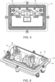
- Figure 5 is a plan view of the reverse (inner) side of a conventional faceplate.
- the drawing shows the two pairs of actuator contacts 40 which, when the faceplate is correctly attached to the back box 22, depress the actuator buttons 34, 36.
- the Applicant has found that, with conventional designs of faceplate of the sort described above, when the faceplate is being fitted, it is possible to position the faceplate, as it is being offered up to the back box, such that the actuator buttons may be depressed before the internal electrical connectors make contact. This may happen especially if the faceplate is not in good alignment with the back box e.g. if the faceplate is tilted in a vertical and/or horizontal plane relative to the back box.
- the present invention is aimed at reducing or eliminating this problem.
- FIG. 6 there is shown a perspective view of a first embodiment of a faceplate in accordance with the present invention.
- the faceplate 24 is shown inverted, so that the internal components of the faceplate are visible.
- These include, in particular, guide means in the form of a pair of projections 50, 50' (circled in the figure), located on respective opposed sides of the faceplate.
- the projections 50,50' extend perpendicularly away from the faceplate and towards the back box, and are of suitable dimensions and positioning to prevent the faceplate from being offered up to the back box at a significant deviation from correct alignment ("significant deviation" for present purposes being more than a 5, 6, 7, 8, 9, 10, 12, 14, 16, 18 or even 20 degrees or more deviation from correct alignment).
- the projections take the form of substantially identical flaps substantially parallel with, and depending from, respective opposed side walls 56, 56' of the faceplate.
- the projections 50, 50' each comprise a recess, within which recess is accommodated a respective earth spring connection 54, 54' formed of metal or other conductive material.
- the projections 50, 50' may be formed of any suitably rigid material and may, for example, be substantially formed of metal or, more preferably, a suitably rigid synthetic plastics material. Typically, the dimensions of the projections 50, 50' will be in the range 12-16mm high and 20-35mm wide
- FIG. 7 there is shown a perspective view of a second embodiment of a faceplate in accordance with the present invention.
- the embodiment is substantially similar to that illustrated in Figure 6 , and equivalent components are indicated by common reference numerals.
- the embodiment shown in Figure 7 comprises two pairs of projections: a first pair 50, 50' located on opposed side walls 56, 56' of the faceplate; and a second pair of projections 60, 60' respectively located on opposed top 62, and bottom 64, walls of the faceplate.
- the guide means may be provided, inter alia, on two opposed walls, or all four walls of the faceplate, depending on the configuration of the internal connectors.
- Different manufacturers' back boxes have different connectors and actuator configurations and may be different shapes, but all potentially can be susceptible to the same problem.
Landscapes
- Engineering & Computer Science (AREA)
- Theoretical Computer Science (AREA)
- Computer Hardware Design (AREA)
- Power Engineering (AREA)
- Human Computer Interaction (AREA)
- Physics & Mathematics (AREA)
- General Engineering & Computer Science (AREA)
- General Physics & Mathematics (AREA)
- Signal Processing (AREA)
- Multimedia (AREA)
- Computer Networks & Wireless Communication (AREA)
- Details Of Connecting Devices For Male And Female Coupling (AREA)
- Connector Housings Or Holding Contact Members (AREA)
Abstract
The invention provides a faceplate for a network signal distribution tap, the faceplate being adapted and configured for removable attachment to a tap back box, the faceplate comprising guide means of suitable dimensions and positioning to prevent the faceplate from being offered up to the back box at a significant deviation from perfect alignment; and a signal distribution tap comprising the faceplate of the invention.
Description
- The present invention relates to a faceplate for a broadband signal distribution tap of the sort used in cable television and broadband networks; a signal distribution tap comprising the faceplate of the invention; a method of making the faceplate; and a method of making an operable signal distribution tap by attaching the faceplate of the invention to a signal distribution tap back box.
- Signal distribution taps are used in cable television (CATV), broadband and other communications networks to connect the networked services to subscriber homes.
- A signal distribution tap comprises a back box and a faceplate. The back box component is essentially permanently-connected to the network, whilst the faceplate is attachable to, and removable from, the back box. The signal distribution tap incorporates a coupler circuit that divides the signal between the output and an internal splitter circuit, which subsequently divides the remaining signal equally between (typically) 2, 4 or 8-way "tap" outputs that connect to subscriber premises via coaxial cables. The faceplate and back box connect electrically via two internal connectors (one for signal in, and one for signal out).
- In a CATV or broadband network the taps are cascaded together, with the output of one tap connected to the input of the next in the chain (see
fig 1 ). To extend the reach of the network, amplifiers are positioned throughout the chain to boost the signal. - Each tap back box contains a mechanically-switched "bypass" circuit that connects (via a "power pass bar" or similar) the tap output to the tap input when the faceplate is removed, thus maintaining power and signal to the rest of the network downstream of the tap. It is important that this switch, referred to as a "Make Before Break" (MBB) switch, engages before the faceplate is disconnected and disengages only after the faceplate is fully installed, so as to maintain signal and power continuity to all downstream equipment. Any interruption to the network power may cause downstream amplifiers to switch off and then have to go through a time-consuming reset procedure, during which signal to the connected subscribers is temporarily blocked.
- It is difficult and time-consuming to replace the tap back boxes once installed in the network and this also causes the signal to all downstream subscribers to be interrupted when it occurs, hence network operators prefer, if possible, to replace only the tap faceplates rather than the entire tap.
- As technology has advanced, the frequency band over which over which CATV or other signals are transmitted has increased, which has required the upgrading of the tap faceplates. The faceplate circuits and components have become more complex and in some cases the faceplates have increased in depth to accommodate larger and/or more numerous components.
- There are several manufacturers of distribution taps with different back box MBB switch configurations, but regardless of the details of the tap design, for all of them it is important that the replacement faceplates always first connect to the internal connectors and only then disengage the MBB switch as the faceplate is mounted. However, particularly with the new faceplates with increased depth, it has become possible when mounting onto the back box to tilt the faceplate at an angle, such that the back box MBB switch disengages before the faceplate internal connectors fully engage, causing power and signal interruption downstream of the tap in question.
- As the required top frequency at which the taps operate has increased, the physical characteristics of existing back boxes have an increasingly detrimental effect on the performance of electrical circuits within. One of the causes of this detrimental effect is the proximity of the power pass bar to the input and output connectors when the faceplate is fitted and the power pass bar is in its disconnected state. A solution to this is to physically raise the portion of the faceplate that contacts with the power pass actuator buttons in the back box (see
Figures 4 and5 below). This has the effect of pushing the actuator buttons further into the back box, thus causing the power pass bar to be positioned further away from the connectors and thereby reducing the negative impact it has on the performance of the tap circuits. - An unwanted consequence of the changing the actuator contact height on the faceplate is that it becomes possible, when mounting onto a back box, to tilt the faceplate at an angle such that the back box MBB switch disengages before the faceplate internal connectors fully engage, causing power and signal interruption downstream of the tap in question.
- The purpose of this invention is to provide a means to ensure when a replacement faceplate is fitted, it is correctly aligned so as not to be possible for the back box bypass switch to open before the faceplate connectors engage.
- In a first aspect the invention provides a faceplate for a network signal distribution tap, the faceplate being adapted and configured for removable attachment to a tap back box, the faceplate comprising guide means of suitable dimensions and positioning to prevent the faceplate from being offered up to the back box at a significant deviation from perfect alignment, and the guide means comprises one or more projections which are substantially parallel with, and depend from, a wall of the faceplate on the inner face of the faceplate, thereby in use to align with and be closely adjacent to internal wall surfaces of a back box. For present purposes the term "significant deviation" means more than a 5, 6, 7, 8, 9, 10, 12, 14, 16, 18 or even 20 degree or more deviation from perfect alignment. The deviation may be in the vertical plane, or in the horizontal plane, or in both the vertical and the horizontal planes.
- The guide means needs to ensure the faceplate will not twist to a significant deviation when being mounted. Advantageously, the guide means may be formed on the inner face of one or more walls of the faceplate. Typically the guide means may be greater than 25% of the total length of an internal wall of the faceplate on which the guide means is mounted. The guide means is desirably also as high as possible (i.e. projecting from the faceplate as far as possible) so as to engage with a guiding portion of the back box as early as possible, but must also be short enough so as not to interfere with the base of the back box when the faceplate is secured in position.
- Preferably the guide means is configured to interact with the back box. In one embodiment, the guide means comprises one or more (preferably a pair) of projections which typically extend away from the faceplate and towards the back box. The one or more projections may comprise a recess within which an earth spring is incorporated. Preferably the one or more projections are substantially parallel with, and depend from, a wall of the faceplate on the inner face of the faceplate (i.e. such that the projections are directed towards the back box when the faceplate is offered up to the back box during attachment of the faceplate to the back box).
- The guide means may be formed of any suitably rigid material and may, for example, be substantially formed of metal or, more preferably, a suitably rigid synthetic plastics material. For simplicity, the guide means comprises projections which are conveniently substantially planar flap-like projections, but this is not essential. Typically, the dimensions of the projections will be in the range 12-16mm high and 20-35mm wide, but the person skilled in the art will appreciate that these dimensions may alter depending on, inter alia, the relative sizes of the back box and faceplate.
- Advantageously, the guide means is positioned so as to fit reasonably snugly within the space defined within the back box when the faceplate is offered up to the back box. More especially, when the faceplate is installed, the guide means may be accommodated within the back box in close proximity to one or more walls of the back box. Conveniently, but not necessarily, the back box may comprise one or more co-operating guide features which co-operate with the guide means, so as to facilitate correct positioning and alignment of the faceplate as it is offered up to the back box during installation. Such co-operating guide features may include, for example, one or more tapered surfaces, which direct the faceplate guide means, and the faceplate generally, into correct positioning and alignment.
- Where the guide means comprises a pair of projections, the pair of projections may be substantially identical, or they may be non-identical. Typically, each of the pair of projections will be positioned on a respective one of opposed side walls or opposed top and bottom walls of the faceplate. The guide means will typically extend along part of the length of each of a pair of opposed walls of the faceplate.
- In another embodiment, the guide means comprises two pairs of projections, with a first pair provided on opposed side walls of the faceplate, and a second pair of projections provided on opposed top & bottom walls of the faceplate. The two pairs of projections may be identical, or may be non-identical.
- In a third embodiment, the guide means comprises at least one pair of projections, with the projections being located at diagonally opposed corners of the faceplate, each of the pair of projections extending partially along one side wall and partially along a top or bottom wall of the faceplate.
- The guide means may comprise one or more (preferably a pair of) substantially continuous flaps, or the flaps may comprise a recess, partition or other type of discontinuity within which another component (especially, an earth contact spring) may be incorporated. Such sprung metal earth contact springs, typically 3mm - 5mm wide, provide electrical continuity between the faceplate and the back box before the signal and power connection is made, thus preventing risk of electrical shock.
- In a second aspect, the invention provides a distribution tap comprising the faceplate of the first aspect of the invention, in operable relationship with a tap back box. As is well-known to those skilled in the art, the faceplate is preferably removably attached to the back box. A convenient manner of effecting such removable attachment is to use one or more screw-threaded engagements to attach the faceplate to the back box.
- In a third aspect the invention provides a method of making the faceplate of the first aspect of the invention, the method comprising the step of forming a distribution tap faceplate, the faceplate comprising guide means as aforesaid. The faceplate may otherwise be essentially conventional.
- In a fourth aspect, the invention provides a method of making an operable distribution tap by operably attaching the faceplate of the invention to a signal distribution tap back box.
- The invention will now be further described by way of illustrative embodiment and with reference to the accompanying drawing figures in which:
-
Figure 1 is a schematic representation of a conventional cable TV network, incorporating a plurality of taps; -
Figure 2 shows a conventional prior art distribution tap, with input and output connections, of the sort used in a typical cable TV network, the tap comprising an 8-way 1.8GHz tap faceplate; -
Figure 3 shows a perspective view of the faceplate of a conventional prior art signal distribution tap, removed from the back box, to expose the connectors for connecting the faceplate to the back box; -
Figure 4 is a perspective view, of the conventional prior art back box (with the faceplate removed), showing various electrical components mounted on the back box; -
Figure 5 is a plan view of the reverse (inner) side of the conventional prior art faceplate; and -
Figures 6 and7 are perspective views of respective embodiments of a faceplate in accordance with the present invention. -
Figure 1 is a schematic representation of part of a typical cable TV network. The network (indicated generally by reference numeral 2) comprises acoaxial cable 4 which carries the TV signal from alocal distribution node 6, to a plurality of network users or subscribers 8-8"", via one or more of the intervening signal distribution (4-way) tap components 10-10"". In order to provide the signal to each of the users or subscribers, the signal is split at each of the tap components. The taps are in a cascade, with the output oftap 10 connected to the input of tap 10', and the output of tap 10' connected to the input oftap 10", and so on. Each tap 10-10ʺʺ also has a plurality of signal outputs which provide equal parts of the split signal to each of the users attached to the particular tap. The network also comprises a plurality ofsignal amplifiers 12 which ensure the users or subscribers receive a sufficiently strong signal via thenetwork 2. -
Figure 2 is a perspective view of a conventional 8-way tap 20, of the sort which may be used in thenetwork 2 shown inFigure 1 . The tap comprises an essentially permanently fixed backbox 22, and a readilyremovable faceplate 24, attached to the back box by a plurality of screws. (Both theback box 22 and thefaceplate 24 are of conventional design). Thefaceplate 24 may be thus easily removed from the back box to permit access to the interior components of the tap for repair or maintenance and to permit upgrades to the tap by installation of a new faceplate with upgraded components and/or functionality. Thetap 20 has anetwork input connection 26 and anetwork output connection 28, respectively connecting the tap to upstream and downstream components in thenetwork 2. Finally, thefaceplate 24 comprises a plurality of (in this instance eight)connectors 25 for connecting to individual users of, or subscribers to, thenetwork 2. -
Figure 3 is a perspective view of thefaceplate 24 from the tap depicted inFigure 2 , removed from the back box and inverted, to show the interior components of the faceplate and, in particular, the pair ofconnectors 30 for making electrical connections between thefaceplate 24 and theback box 22. -
Figure 4 is a perspective view of theback box 22, from the tap depicted inFigure 2 , with the faceplate removed, such that the interior components of the back box are visible. These include, in particular, a pair ofconnectors 32 for making electrical connection with theconnectors 30 of thefaceplate 24 shown inFigure 3 . Also visible are two pairs of bypassswitch activator buttons pass connection bar 38, disposed between the bypassswitch actuator buttons - When the faceplate is removed from the back box, the
actuator buttons pass connection bar 38 contacts the bottom of the input and output connectors, thus allowing power and signal to flow through the tap to the output and onto the downstream side of the network uninterrupted when the faceplate is removed. -
Figure 5 is a plan view of the reverse (inner) side of a conventional faceplate. The drawing shows the two pairs ofactuator contacts 40 which, when the faceplate is correctly attached to theback box 22, depress theactuator buttons - The Applicant has found that, with conventional designs of faceplate of the sort described above, when the faceplate is being fitted, it is possible to position the faceplate, as it is being offered up to the back box, such that the actuator buttons may be depressed before the internal electrical connectors make contact. This may happen especially if the faceplate is not in good alignment with the back box e.g. if the faceplate is tilted in a vertical and/or horizontal plane relative to the back box. The present invention is aimed at reducing or eliminating this problem.
- Referring to
Figure 6 , there is shown a perspective view of a first embodiment of a faceplate in accordance with the present invention. Thefaceplate 24 is shown inverted, so that the internal components of the faceplate are visible. These include, in particular, guide means in the form of a pair ofprojections 50, 50' (circled in the figure), located on respective opposed sides of the faceplate. Theprojections 50,50' extend perpendicularly away from the faceplate and towards the back box, and are of suitable dimensions and positioning to prevent the faceplate from being offered up to the back box at a significant deviation from correct alignment ("significant deviation" for present purposes being more than a 5, 6, 7, 8, 9, 10, 12, 14, 16, 18 or even 20 degrees or more deviation from correct alignment). The projections take the form of substantially identical flaps substantially parallel with, and depending from, respectiveopposed side walls 56, 56' of the faceplate. - The
projections 50, 50' each comprise a recess, within which recess is accommodated a respectiveearth spring connection 54, 54' formed of metal or other conductive material. - The
projections 50, 50' may be formed of any suitably rigid material and may, for example, be substantially formed of metal or, more preferably, a suitably rigid synthetic plastics material. Typically, the dimensions of theprojections 50, 50' will be in the range 12-16mm high and 20-35mm wide - Referring to
Figure 7 , there is shown a perspective view of a second embodiment of a faceplate in accordance with the present invention. The embodiment is substantially similar to that illustrated inFigure 6 , and equivalent components are indicated by common reference numerals. The embodiment shown inFigure 7 comprises two pairs of projections: afirst pair 50, 50' located onopposed side walls 56, 56' of the faceplate; and a second pair ofprojections 60, 60' respectively located on opposed top 62, and bottom 64, walls of the faceplate. - As is apparent from the foregoing, the guide means may be provided, inter alia, on two opposed walls, or all four walls of the faceplate, depending on the configuration of the internal connectors. Different manufacturers' back boxes have different connectors and actuator configurations and may be different shapes, but all potentially can be susceptible to the same problem.
Claims (14)
- A faceplate for a network signal distribution tap, the faceplate being adapted and configured for removable attachment to a tap back box, the faceplate comprising guide means of suitable dimensions and positioning to prevent the faceplate from being offered up to the back box at a significant deviation from perfect alignment, and the guide means comprises one or more projections which are substantially parallel with, and depend from, a wall of the faceplate on the inner face of the faceplate.
- A faceplate according to claim 1, wherein the one or more projections extend away from the faceplate and towards the back box.
- A faceplate according to claim 1 or claim 2, wherein the one or more projections comprise a recess within which an earth spring is incorporated.
- A faceplate according to any of the preceding claims wherein the one or more projections extend along part of the length of each of a pair of opposed walls of the faceplate.
- A faceplate according to any of the preceding claims, wherein the one or more projections are a single pair of projections.
- A faceplate according to claim 5, wherein each projection of the pair of projections is positioned on a respective one of opposed side walls or opposed top and bottom walls of the faceplate.
- A faceplate according to any one of claims 1 to 4, wherein the guide means comprises at least one pair of projections, with the projections being located at diagonally opposed corners of the faceplate, each of the pair of projections extending partially along one side wall and partially along a top or bottom wall of the faceplate.
- A faceplate according to any of claims 1 to 4, wherein the guide means comprises two pairs of projections; a first pair provided on opposed side walls of the faceplate, and a second pair of projections provided on opposed top and bottom walls of the faceplate.
- A faceplate according to any one of the preceding claims, wherein one or more projections comprises a substantially continuous flap comprising a recess, partition or other type of discontinuity within which an earth spring is incorporated.
- A distribution tap comprising a faceplate in accordance with any one of the preceding claims, removably attached in operable relationship with a tap back box.
- A distribution tap according to claim 10, wherein the back box comprises one or more co-operating guide features which co-operate with the one or more projections so as to facilitate correct positioning and alignment of the faceplate as it is offered up to the back box during installation.
- A distribution tap according to claim 11, wherein the co-operating guide features comprise one or more tapered surfaces, which direct the faceplate guide means, and the faceplate generally, into correct positioning and alignment.
- A method of making a faceplate according to any one of claims 1 to 9, the method comprising the step of forming a distribution tap faceplate, the faceplate comprising guide means of suitable dimensions and positioning to prevent the faceplate from being offered up to the back box at a significant deviation from perfect alignment, and the guide means comprises one or more projections which are substantially parallel with, and depend from, a wall of the faceplate on the inner face of the faceplate.
- A method of making a faceplate according to claim 13, wherein the one or more projections comprise a recess within which an earth spring is incorporated.
Applications Claiming Priority (1)
| Application Number | Priority Date | Filing Date | Title |
|---|---|---|---|
| GBGB2312551.1A GB202312551D0 (en) | 2023-08-17 | 2023-08-17 | Improvements in or relating to signal tap faceplate alignment |
Publications (1)
| Publication Number | Publication Date |
|---|---|
| EP4510606A1 true EP4510606A1 (en) | 2025-02-19 |
Family
ID=88189791
Family Applications (1)
| Application Number | Title | Priority Date | Filing Date |
|---|---|---|---|
| EP24188676.1A Pending EP4510606A1 (en) | 2023-08-17 | 2024-07-15 | Improvements in or relating to signal tap faceplate alignment |
Country Status (4)
| Country | Link |
|---|---|
| US (1) | US20250060798A1 (en) |
| EP (1) | EP4510606A1 (en) |
| CA (1) | CA3246401A1 (en) |
| GB (2) | GB202312551D0 (en) |
Citations (3)
| Publication number | Priority date | Publication date | Assignee | Title |
|---|---|---|---|---|
| WO1996034428A1 (en) * | 1995-04-24 | 1996-10-31 | Raychem Corporation | Coaxial cable tap |
| US20040187163A1 (en) * | 2003-03-20 | 2004-09-23 | Yung-Liang Chang | Addressable tap used in cable TV network |
| US20140017919A1 (en) * | 2010-03-03 | 2014-01-16 | Indiblock, Llc | Distribution Tap Security Cover |
Family Cites Families (2)
| Publication number | Priority date | Publication date | Assignee | Title |
|---|---|---|---|---|
| US9351414B1 (en) * | 2014-09-18 | 2016-05-24 | The Directv Group, Inc. | Television distribution component enclosure |
| CN212343961U (en) * | 2020-06-11 | 2021-01-12 | 广州世祥教育科技有限公司 | Live broadcast streaming media distribution interface data distribution refuting stream system convenient for port maintenance |
-
2023
- 2023-08-17 GB GBGB2312551.1A patent/GB202312551D0/en not_active Ceased
-
2024
- 2024-07-11 CA CA3246401A patent/CA3246401A1/en active Pending
- 2024-07-15 GB GB2410281.6A patent/GB2633898A/en active Pending
- 2024-07-15 EP EP24188676.1A patent/EP4510606A1/en active Pending
- 2024-07-22 US US18/780,437 patent/US20250060798A1/en active Pending
Patent Citations (3)
| Publication number | Priority date | Publication date | Assignee | Title |
|---|---|---|---|---|
| WO1996034428A1 (en) * | 1995-04-24 | 1996-10-31 | Raychem Corporation | Coaxial cable tap |
| US20040187163A1 (en) * | 2003-03-20 | 2004-09-23 | Yung-Liang Chang | Addressable tap used in cable TV network |
| US20140017919A1 (en) * | 2010-03-03 | 2014-01-16 | Indiblock, Llc | Distribution Tap Security Cover |
Also Published As
| Publication number | Publication date |
|---|---|
| GB2633898A (en) | 2025-03-26 |
| GB202410281D0 (en) | 2024-08-28 |
| GB202312551D0 (en) | 2023-10-04 |
| CA3246401A1 (en) | 2025-06-13 |
| US20250060798A1 (en) | 2025-02-20 |
Similar Documents
| Publication | Publication Date | Title |
|---|---|---|
| US6292371B1 (en) | Multiple cavity, multiple port modular CATV housing | |
| US5756935A (en) | Screwless seizure bypass platform | |
| US5581134A (en) | Bypass switch for RF networks | |
| US5814905A (en) | Cable TV multi-tap with uninterruptable signal/power throughput | |
| KR19980703156A (en) | System for distributing AC and RF signals to taps | |
| US5850165A (en) | Non-interruptable tap and method | |
| US12388223B2 (en) | High frequency uninterruptible signal and power bypass with rocker mechanism | |
| US6081169A (en) | Circuitry for use with coaxial cable distribution networks | |
| US20250060798A1 (en) | Signal tap faceplate alignment | |
| US8869223B2 (en) | Increased cable television tap bandwidth utilizing existing tap housings | |
| US20250343013A1 (en) | Tap modification device configured to provide enhanced operating frequency range | |
| US8646018B2 (en) | Increased cable television tap bandwidth utilizing existing tap housings | |
| US20250254372A1 (en) | Module for a cable tv network distribution tap | |
| US12519902B2 (en) | RF pass band notch removal in broadband signal taps | |
| US20250253104A1 (en) | Plug-in bypass module for a cable tv network distribution tap | |
| US20250253604A1 (en) | Jumper tool for a cable tv network distribution tap | |
| US9819389B2 (en) | Single path signal conditioner for bi-directional radio frequency signals in a telecommunications network | |
| US12550270B2 (en) | Face plate for cable tap unit | |
| CA3251684A1 (en) | Plug-in bypass module for a cable tv network distribution tap | |
| CZ98397A3 (en) | Distributor | |
| US20030099100A1 (en) | Adaptive module for housings | |
| CA2846525A1 (en) | Increased cable television tap bandwidth utilizing existing tap housings |
Legal Events
| Date | Code | Title | Description |
|---|---|---|---|
| PUAI | Public reference made under article 153(3) epc to a published international application that has entered the european phase |
Free format text: ORIGINAL CODE: 0009012 |
|
| STAA | Information on the status of an ep patent application or granted ep patent |
Free format text: STATUS: THE APPLICATION HAS BEEN PUBLISHED |
|
| AK | Designated contracting states |
Kind code of ref document: A1 Designated state(s): AL AT BE BG CH CY CZ DE DK EE ES FI FR GB GR HR HU IE IS IT LI LT LU LV MC ME MK MT NL NO PL PT RO RS SE SI SK SM TR |
|
| STAA | Information on the status of an ep patent application or granted ep patent |
Free format text: STATUS: REQUEST FOR EXAMINATION WAS MADE |
|
| 17P | Request for examination filed |
Effective date: 20250812 |