EP4510439A1 - Electric motor calibration - Google Patents
Electric motor calibration Download PDFInfo
- Publication number
- EP4510439A1 EP4510439A1 EP23191234.6A EP23191234A EP4510439A1 EP 4510439 A1 EP4510439 A1 EP 4510439A1 EP 23191234 A EP23191234 A EP 23191234A EP 4510439 A1 EP4510439 A1 EP 4510439A1
- Authority
- EP
- European Patent Office
- Prior art keywords
- calibration
- control system
- electric motor
- machine control
- position sensor
- Prior art date
- Legal status (The legal status is an assumption and is not a legal conclusion. Google has not performed a legal analysis and makes no representation as to the accuracy of the status listed.)
- Withdrawn
Links
Images
Classifications
-
- H—ELECTRICITY
- H02—GENERATION; CONVERSION OR DISTRIBUTION OF ELECTRIC POWER
- H02P—CONTROL OR REGULATION OF ELECTRIC MOTORS, ELECTRIC GENERATORS OR DYNAMO-ELECTRIC CONVERTERS; CONTROLLING TRANSFORMERS, REACTORS OR CHOKE COILS
- H02P6/00—Arrangements for controlling synchronous motors or other dynamo-electric motors using electronic commutation dependent on the rotor position; Electronic commutators therefor
- H02P6/14—Electronic commutators
- H02P6/16—Circuit arrangements for detecting position
Definitions
- This disclosure relates to vehicles using electric motors controlled by inverters. Particularly, this disclosure relates to calibration of a position sensor of an electric motor.
- An inverter is a device that converts DC power to AC power used in an electric motor.
- the inverter can change the speed at which the motor rotates by adjusting the frequency of the alternating current.
- a calibration of the position sensor of the electric motor needs to be performed.
- An electric motor position offset calibration is a basic calibration done to all electric motors before they can be used.
- the calibration may be performed using third party external software, such as the manufacturer's programming software. This procedure requires a connection from a laptop computer to the inverter with a suitable programming cable.
- maintenance personnel needs to be trained for using the third party software. Alternatively, special supplier maintenance may be required.
- each inverter needs respective different software for the calibration of the position sensor of the electric motor.
- Example embodiments of the present disclosure disclose an efficient solution for performing a calibration of a position sensor of the electric motor using a machine control system associated with a vehicle. This and other benefits may be achieved by the features of the independent claims. Further advantageous implementation forms are provided in the dependent claims, the description, and the drawings.
- a calibration method for a machine control system controlling an inverter associated with an electric motor comprises providing a human-machine interface associated with the machine control system for calibrating a position sensor of the electric motor; receiving, via the human-machine interface, a user input initiating the calibration of the position sensor of the electric motor; performing with the machine control system the calibration of the position sensor of the electric motor in response to receiving the user input; and providing, via the human-machine interface, a calibration result.
- a machine control system controlling an inverter associated with an electric motor.
- the machine control system comprises at least one processor and at least one memory including computer program code, the at least one memory and the computer program code configured to with the at least one processor, cause the machine control system at least to provide a human-machine interface associated with the machine control system for calibrating a position sensor of the electric motor; receive, via the human-machine interface, a user input initiating the calibration of the position sensor of the electric motor; perform the calibration of the position sensor of the electric motor in response to receiving the user input; and provide, via the human-machine interface, a calibration result.
- a vehicle comprising a machine control system according to the second aspect, at least one electric motor and at least one inverter, each inverter being associated with a respective electric motor.
- a computer program comprising instructions for causing a machine control system according to the second aspect to carry out the method according to the first aspect.
- a non-transitory computer readable medium comprises a computer program comprising instructions for causing a machine control system according to the second aspect to carry out the method according to the first aspect.
- a machine control system controlling an inverter associated with an electric motor.
- the machine control system comprises means for: providing a human-machine interface associated with the machine control system for calibrating a position sensor of the electric motor; receiving, via the human-machine interface, a user input initiating the calibration of the position sensor of the electric motor; performing the calibration of the position sensor of the electric motor in response to receiving the user input; and providing, via the human-machine interface, a calibration result.
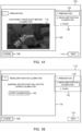
- FIGS. 1A-1E illustrate example graphical user interface views 100, 114, 122, 126, 134 associated with a calibration procedure of a position sensor of an electric motor according to an example embodiment.
- the graphical user interface views 100, 114, 122, 126, 134 may be provided by a machine control system controlling operations of a vehicle comprising the electric motor.
- the illustrated graphical user interface views 100, 114, 122, 126, 134 are examples of a human-machine interface that can used to interact with a user.
- physical button(s) and/or voice input/output may be used.
- a phase of the calibration procedure may be indicated in an information section 102 of the graphical user interface view 100.
- An information section 106 associated with a preparation phase 104 may provide instructions to a user how to proceed with the calibration. For example, an instruction may be given to the user to disconnect a drive shaft before calibration. In an example embodiment, an image 112 emphasizing this may be provided to the user. The user may cancel the calibration procedure via a selection item 108, for example, a button, or to proceed further by selecting a selection item 110.
- the graphical user interface view 114 may illustrate a second phase 116 relating to the calibration procedure.
- the user is able to start the actual calibration by selecting a selection item 120 from an information section 118.
- the information section 118 may also issue a warning to the user that a motor shaft will rotate during the calibration.
- the inverter rotates the electric motor slightly, typically only one rotation, in order to identify an orientation of the position sensor with respect to a rotor of the electric motor.
- the machine control system may send at least one command to the inverter to allow the calibration. The user can select to start the calibration by selecting the selection item 120 or cancel the calibration procedure by selecting the selection item 108.
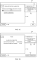
- the graphical user interface view 122 may be provided after the user has started the calibration via the selection item 120.
- An information section 124 may provide status information about the calibration, for example, via a progressing bar.
- the graphical user interface view 126 may illustrate a third phase 128, when the calibration has been completed.
- An information section 130 may provide results relating to the calibration.
- the results may comprise a motor position offset identified during the calibration and a maximum calibration torque measured.
- the user may cancel the calibration process via the selection item 108 or alternatively accept the calibration result via a selection item 132.
- the graphical user interface view 134 illustrates a situation when the calibration has failed.
- a reason for the failure may be that a maximum calibration torque threshold, for example, 50 Nm, has been exceeded, as indicated by an information section 136.
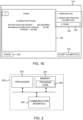
- FIG. 2 illustrates a block diagram of a machine control system 200 controlling an inverter associated with an electric motor.
- the machine control system 200 may be configured to practice one or more example embodiments discussed herein.
- the machine control system 200 may comprise at least one processor 202 and at least one memory 204 including computer program code 206, wherein the at least one memory 204 with the computer program 206 code may be configured, with the at least one processor 202, to cause the machine control system 200 at least to provide a human-machine interface associated with the machine control system for calibrating a position sensor of the electric motor; receive, via the human-machine interface, a user input initiating the calibration of the position sensor of the electric motor; perform the calibration of the position sensor of the electric motor in response to receiving the user input; and provide, via the human-machine interface, a calibration result.
- the machine control system 200 may also include a communication interface 208 for wired and/or wireless communication.
- the communication interface 208 may enable, for example, connections to peripheral components, such as a screen, touchscreen, a physical button, or a keyboard, that a user may configure the machine control system 200 with, or via which the user may obtain information from or provide information to the machine control system 200. Further, the communication interface 208 may be configured to exchange data between different devices, for example, the inverter and a display configured to provide a graphical user interface.
- the at least one processor 202 and/or the at least one memory 204 may be configured to implement this functionality.
- this functionality may be implemented using program code 206 comprised, for example, in the at least one memory 204.
- the machine control system 200 comprises a processor or processor circuitry, such as for example a microcontroller, configured by the program code 206, when executed, to execute the embodiments of the operations and functionality described herein.
- the program code 206 is provided as an example of instructions which, when executed by the at least one processor 202, cause performance of machine control system 200.
- An example embodiment of a computer program comprises instructions, stored in a computer-readable storage medium, that causes a machine control system to perform the method(s) described herein, such as the method illustrated in FIG. 4 .
- the functionality described herein can be performed, at least in part, by one or more hardware logic components.
- illustrative types of hardware logic components include field-programmable gate arrays (FPGAs), application-specific integrated circuits (ASICs), application-specific standard products (ASSPs), system-on-a-chip systems (SOCs), complex programmable logic devices (CPLDs), graphics processing units (GPUs), or the like.
- the machine control system 200 may be configured to perform, or cause performance of, method(s) described herein or comprise means for performing method(s) described herein.
- the means may comprise the at least one processor 202, the at least one memory 204 including program code 206 configured to, when executed by the at least one processor 202, cause the machine control system 200 to perform the method(s).
- computer program instructions may be executed on means providing generic processing functions. Such means may be embedded for example in a personal computer, a tablet computer or the like.
- the method(s) may thus be computer-implemented, for example based algorithm(s) executable by the generic processing functions, an example of which is the at least one processor 202.
- the means may comprise transmission or reception means, for example one or more radio transmitters or receivers, which may be coupled or be configured to be coupled to one or more antennas, or transmitter(s) or receiver(s) of a wired communication interface.
- transmission or reception means for example one or more radio transmitters or receivers, which may be coupled or be configured to be coupled to one or more antennas, or transmitter(s) or receiver(s) of a wired communication interface.
- FIG. 3 illustrates a system according to an example embodiment.
- the system comprises a machine control system 200 configured to control operations of a vehicle, for example, a mining vehicle or an underground mining vehicle.
- the system further comprises at least one inverter 300 communicatively connected to the machine control system 200, and at least one electric motor 302.
- Each inverter 300 may be associated with a respective electric motor 302.
- the inverter 300 converts DC power to AC power used in the electric motor 302.
- the inverter 300 can change the speed at which the electric motor 302 rotates by adjusting the frequency of the alternating current. If there is more than one electric motor 302 in the vehicle, a corresponding inverter is associated with each electric motor.
- the system further comprises a human-machine interface 304.
- the machine control system 200 may be configured to control the human-machine interface 304 to interact with a user.
- the human-machine interface 304 may refer to one or more interfaces with which a human may interact with the machine control system 200.
- the human-machine interface 304 may refer to a graphical user interface provided by a display or a touch-sensitive display for a user to perform the calibration procedure discussed herein.
- the human-machine interface 304 may comprise one or more other interfaces.
- a physical button may be used to enable the user input for initiating the calibration.
- the calibration result may then be provided, for example, via a graphical user interface or via audio output.
- both the initiation of the calibration and the calibration result may be provided via audio output.
- the user may provide the user input via a voice command, and the calibration result may be provided using predefined audio signals or voiced text output.
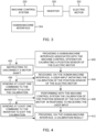
- FIG. 4 illustrates a calibration method for a machine control system controlling an inverter associated with an electric motor according to an example embodiment.
- the method may be a computer-implemented method that may be executed, for example, by the machine control system 200.
- a human-machine interface associated with the machine control system for calibrating a position sensor of the electric motor may be provided.
- the human-machine interface for example, a graphical user interface, may be used to guide a user through the calibration procedure.
- the user may be instructed, via the human-machine interface, to disconnect a motor shaft before initiating the calibration of the position sensor of the electric motor.
- a user input initiating the calibration of the position sensor of the electric motor may be received via the human-machine interface.
- the human-machine interface may provide a selection item to initiate the calibration.
- at least one of instructions and warnings relating to the calibration may be additionally provided.
- at 406 at least one command may be sent to the inverter to allow the calibration.
- the calibration of the position sensor of the electric motor may be performed with the machine control system in response to receiving the user input.
- the machine control system may control the inverter to operate the electric motor in order to perform the calibration of the position sensor of the electric motor.
- the machine control system may be configured to send at least one command to the inverter to exit the calibration.
- a calibration result may be provided via the human-machine interface.
- the calibration result may indicate a success or failure of the calibration.
- the calibration result may comprise at least one of a motor position offset and a maximum calibration torque.
- a calibration method for a machine control system controlling an inverter associated with an electric motor may be provided.
- the method comprises providing a human-machine interface associated with the machine control system for calibrating a position sensor of the electric motor; receiving, via the human-machine interface, a user input initiating the calibration of the position sensor of the electric motor; performing with the machine control system the calibration of the position sensor of the electric motor in response to receiving the user input; and providing, via the human-machine interface, a calibration result.
- the method may further comprise sending at least one command to the inverter to allow the calibration.
- the method may further comprise instructing, via the human-machine interface, to disconnect a motor shaft before initiating the calibration of the position sensor of the electric motor.
- the calibration result may comprise at least one of a motor position offset and a maximum calibration torque.
- the calibration result may comprise a calibration failure indication.
- the method may further comprise sending at least one command to the inverter to exit the calibration after performing with the machine control system the calibration of the position sensor of the electric motor.
- a machine control system controlling an inverter associated with an electric motor may be provided.
- the machine control system comprises at least one processor and at least one memory including computer program code, the at least one memory and the computer program code configured to with the at least one processor, cause the machine control system at least to provide a human-machine interface associated with the machine control system for calibrating a position sensor of the electric motor; receive, via the human-machine interface, a user input initiating the calibration of the position sensor of the electric motor; perform the calibration of the position sensor of the electric motor in response to receiving the user input; and provide, via the human-machine interface, a calibration result.
- the at least one memory and the computer program code may be configured to, with the at least one processor, cause the machine control system at least to send at least one command to the inverter to allow the calibration.
- the at least one memory and the computer program code may be configured to, with the at least one processor, cause the machine control system at least to instruct, via the human-machine interface, to disconnect a motor shaft before initiating the calibration of the position sensor of the electric motor.
- the calibration result may comprise at least one of a motor position offset and a maximum calibration torque.
- the calibration result may comprise a calibration failure indication.
- the at least one memory and the computer program code may be configured to, with the at least one processor, cause the machine control system at least to send at least one command to the inverter to exit the calibration after performing with the machine control system the calibration of the position sensor of the electric motor.
- a vehicle comprising the machine control system discussed above, at least one electric motor and at least one inverter, each inverter being associated with a respective electric motor, may be provided.
- a computer program comprising instructions for causing a machine control system discussed above to carry out the method discussed above may be provided.
- a non-transitory computer readable medium comprises a computer program instructions for causing a machine control system discussed above to carry out the method discussed above may be provided.
- a machine control system controlling an inverter associated with an electric motor may be provided.
- the machine control system comprises means for: providing a human-machine interface associated with the machine control system for calibrating a position sensor of the electric motor; receiving, via the human-machine interface, a user input initiating the calibration of the position sensor of the electric motor; performing the calibration of the position sensor of the electric motor in response to receiving the user input; and providing, via the human-machine interface, a calibration result.
- One or more of the examples and example embodiments discussed above may enable a solution in which third party software solutions for calibrating a position sensor of the electric motor is no longer needed. Further, one or more of the examples and example embodiments discussed above may enable a solution in which the calibration can be easily performed, for example, during a production phase without special personnel or specially trained personnel. Further, one or more of the examples and example embodiments discussed above may enable a solution in which a commissioning time of electric motors is shortened as the calibration can be performed efficiently.
- the commissioning may comprise, for example, the following: software installation, calibration, adjustments and operation verification. When the calibration can be performed efficiently, the commissioning time becomes shorter.
- one or more of the examples and example embodiments discussed above may enable a solution in which a human-machine interface, for example, a graphical user interface, enables only required functions for a user for performing the calibration and guides the user safely throughout the calibration procedure. Further, one or more of the examples and example embodiments discussed above may enable a solution in which a calibration procedure, when an existing inverter or electric motor has been replaced with a new inverter or electric motor, can be performed efficiently and safely.
- a human-machine interface for example, a graphical user interface
Landscapes
- Engineering & Computer Science (AREA)
- Power Engineering (AREA)
- Control Of Electric Motors In General (AREA)
- Control Of Ac Motors In General (AREA)
Abstract
According to an aspect, there is provided a calibration method for a machine control system controlling an inverter associated with an electric motor. The method comprises providing a human-machine interface associated with the machine control system for calibrating a position sensor of the electric motor; receiving, via the human-machine interface, a user input initiating the calibration of the position sensor of the electric motor; performing with the machine control system the calibration of the position sensor of the electric motor in response to receiving the user input; and providing, via the human-machine interface, a calibration result.
Description
- This disclosure relates to vehicles using electric motors controlled by inverters. Particularly, this disclosure relates to calibration of a position sensor of an electric motor.
- Various machines, for example, mining vehicles, use electric motors. An inverter is a device that converts DC power to AC power used in an electric motor. The inverter can change the speed at which the motor rotates by adjusting the frequency of the alternating current. Before the electric motor can be used, a calibration of the position sensor of the electric motor needs to be performed. An electric motor position offset calibration is a basic calibration done to all electric motors before they can be used. The calibration may be performed using third party external software, such as the manufacturer's programming software. This procedure requires a connection from a laptop computer to the inverter with a suitable programming cable. Furthermore, in order to perform calibrations, maintenance personnel needs to be trained for using the third party software. Alternatively, special supplier maintenance may be required. Further, if a vehicle manufacturer uses several different inverters, each inverter needs respective different software for the calibration of the position sensor of the electric motor.
- This summary is provided to introduce a selection of concepts in a simplified form that are further described below in the detailed description. This summary is not intended to identify key features or essential features of the claimed subject matter, nor is it intended to be used to limit the scope of the claimed subject matter. The scope of protection sought for various embodiments of the present disclosure is set out by the independent claims.
- Example embodiments of the present disclosure disclose an efficient solution for performing a calibration of a position sensor of the electric motor using a machine control system associated with a vehicle. This and other benefits may be achieved by the features of the independent claims. Further advantageous implementation forms are provided in the dependent claims, the description, and the drawings.
- According to a first aspect, there is provided a calibration method for a machine control system controlling an inverter associated with an electric motor. The method comprises providing a human-machine interface associated with the machine control system for calibrating a position sensor of the electric motor; receiving, via the human-machine interface, a user input initiating the calibration of the position sensor of the electric motor; performing with the machine control system the calibration of the position sensor of the electric motor in response to receiving the user input; and providing, via the human-machine interface, a calibration result.
- According to a second aspect, there is provided a machine control system controlling an inverter associated with an electric motor. The machine control system comprises at least one processor and at least one memory including computer program code, the at least one memory and the computer program code configured to with the at least one processor, cause the machine control system at least to provide a human-machine interface associated with the machine control system for calibrating a position sensor of the electric motor; receive, via the human-machine interface, a user input initiating the calibration of the position sensor of the electric motor; perform the calibration of the position sensor of the electric motor in response to receiving the user input; and provide, via the human-machine interface, a calibration result.
- According to a third aspect, there is provided a vehicle comprising a machine control system according to the second aspect, at least one electric motor and at least one inverter, each inverter being associated with a respective electric motor.
- According to a fourth aspect, there is provided a computer program comprising instructions for causing a machine control system according to the second aspect to carry out the method according to the first aspect.
- According to a fifth aspect, a non-transitory computer readable medium comprises a computer program comprising instructions for causing a machine control system according to the second aspect to carry out the method according to the first aspect.
- According to a sixth aspect, there is provided a machine control system controlling an inverter associated with an electric motor. The machine control system comprises means for: providing a human-machine interface associated with the machine control system for calibrating a position sensor of the electric motor; receiving, via the human-machine interface, a user input initiating the calibration of the position sensor of the electric motor; performing the calibration of the position sensor of the electric motor in response to receiving the user input; and providing, via the human-machine interface, a calibration result.
- The accompanying drawings, which are included to provide a further understanding of the example embodiments and constitute a part of this specification, illustrate examples and together with the description help to explain the principles of the example embodiments. In the drawings:
-
FIG. 1A illustrates an example graphical user interface view associated with a calibration procedure of a position sensor of an electric motor according to an example embodiment. -
FIG. 1B illustrates an example graphical user interface view associated with a calibration procedure of a position sensor of an electric motor according to an example embodiment. -
FIG. 1C illustrates an example graphical user interface view associated with a calibration procedure of a position sensor of an electric motor according to an example embodiment. -
FIG. 1D illustrates an example graphical user interface view associated with a calibration procedure of a position sensor of an electric motor according to an example embodiment. -
FIG. 1E illustrates an example graphical user interface view associated with a calibration procedure of a position sensor of an electric motor according to an example embodiment. -
FIG. 2 illustrates a machine control system according to an example embodiment. -
FIG. 3 illustrates a system according to an example embodiment. -
FIG. 4 illustrates a calibration method for a machine control system controlling an inverter associated with an electric motor according to an example embodiment. - Like reference numerals are used to designate like parts in the accompanying drawings.
- Reference will now be made in detail to embodiments, examples of which are illustrated in the accompanying drawings. The detailed description provided below in connection with the appended drawings is intended as a description of the present examples and is not intended to represent the only forms in which the present example may be constructed or utilized. The detailed description sets forth a solution for calibrating a position sensor of an electric motor of a vehicle using a machine control system associated with the vehicle.
-
FIGS. 1A-1E illustrate example graphicaluser interface views user interface views - A phase of the calibration procedure may be indicated in an
information section 102 of the graphicaluser interface view 100. Aninformation section 106 associated with apreparation phase 104 may provide instructions to a user how to proceed with the calibration. For example, an instruction may be given to the user to disconnect a drive shaft before calibration. In an example embodiment, animage 112 emphasizing this may be provided to the user. The user may cancel the calibration procedure via aselection item 108, for example, a button, or to proceed further by selecting aselection item 110. - The graphical
user interface view 114 may illustrate asecond phase 116 relating to the calibration procedure. In thesecond phase 116, the user is able to start the actual calibration by selecting aselection item 120 from aninformation section 118. Theinformation section 118 may also issue a warning to the user that a motor shaft will rotate during the calibration. During the calibration, the inverter rotates the electric motor slightly, typically only one rotation, in order to identify an orientation of the position sensor with respect to a rotor of the electric motor. When the calibration is started, the machine control system may send at least one command to the inverter to allow the calibration. The user can select to start the calibration by selecting theselection item 120 or cancel the calibration procedure by selecting theselection item 108. - The graphical
user interface view 122 may be provided after the user has started the calibration via theselection item 120. Aninformation section 124 may provide status information about the calibration, for example, via a progressing bar. - The graphical
user interface view 126 may illustrate athird phase 128, when the calibration has been completed. Aninformation section 130 may provide results relating to the calibration. For example, the results may comprise a motor position offset identified during the calibration and a maximum calibration torque measured. The user may cancel the calibration process via theselection item 108 or alternatively accept the calibration result via aselection item 132. - The graphical
user interface view 134 illustrates a situation when the calibration has failed. A reason for the failure may be that a maximum calibration torque threshold, for example, 50 Nm, has been exceeded, as indicated by aninformation section 136. -
FIG. 2 illustrates a block diagram of amachine control system 200 controlling an inverter associated with an electric motor. Themachine control system 200 may be configured to practice one or more example embodiments discussed herein. - The
machine control system 200 may comprise at least oneprocessor 202 and at least onememory 204 includingcomputer program code 206, wherein the at least onememory 204 with thecomputer program 206 code may be configured, with the at least oneprocessor 202, to cause themachine control system 200 at least to provide a human-machine interface associated with the machine control system for calibrating a position sensor of the electric motor; receive, via the human-machine interface, a user input initiating the calibration of the position sensor of the electric motor; perform the calibration of the position sensor of the electric motor in response to receiving the user input; and provide, via the human-machine interface, a calibration result. - The
machine control system 200 may also include acommunication interface 208 for wired and/or wireless communication. Thecommunication interface 208 may enable, for example, connections to peripheral components, such as a screen, touchscreen, a physical button, or a keyboard, that a user may configure themachine control system 200 with, or via which the user may obtain information from or provide information to themachine control system 200. Further, thecommunication interface 208 may be configured to exchange data between different devices, for example, the inverter and a display configured to provide a graphical user interface. - When the
machine control system 200 is configured to implement some functionality, some component and/or components ofmachine control system 200, for example, the at least oneprocessor 202 and/or the at least onememory 204, may be configured to implement this functionality. Furthermore, when the at least oneprocessor 202 is configured to implement some functionality, this functionality may be implemented usingprogram code 206 comprised, for example, in the at least onememory 204. - The functionality described herein may be performed, at least in part, by one or more computer program product components such as software components. According to an example embodiment, the
machine control system 200 comprises a processor or processor circuitry, such as for example a microcontroller, configured by theprogram code 206, when executed, to execute the embodiments of the operations and functionality described herein. Theprogram code 206 is provided as an example of instructions which, when executed by the at least oneprocessor 202, cause performance ofmachine control system 200. - An example embodiment of a computer program comprises instructions, stored in a computer-readable storage medium, that causes a machine control system to perform the method(s) described herein, such as the method illustrated in
FIG. 4 . - Alternatively, or in addition, the functionality described herein can be performed, at least in part, by one or more hardware logic components. For example, and without limitation, illustrative types of hardware logic components that can be used include field-programmable gate arrays (FPGAs), application-specific integrated circuits (ASICs), application-specific standard products (ASSPs), system-on-a-chip systems (SOCs), complex programmable logic devices (CPLDs), graphics processing units (GPUs), or the like.
- The
machine control system 200 may be configured to perform, or cause performance of, method(s) described herein or comprise means for performing method(s) described herein. In one example, the means may comprise the at least oneprocessor 202, the at least onememory 204 includingprogram code 206 configured to, when executed by the at least oneprocessor 202, cause themachine control system 200 to perform the method(s). In general, computer program instructions may be executed on means providing generic processing functions. Such means may be embedded for example in a personal computer, a tablet computer or the like. The method(s) may thus be computer-implemented, for example based algorithm(s) executable by the generic processing functions, an example of which is the at least oneprocessor 202. The means may comprise transmission or reception means, for example one or more radio transmitters or receivers, which may be coupled or be configured to be coupled to one or more antennas, or transmitter(s) or receiver(s) of a wired communication interface. Although themachine control system 200 is illustrated as a single device, it is appreciated that, wherever applicable, functions of themachine control system 200 may be distributed to a plurality of devices. -
FIG. 3 illustrates a system according to an example embodiment. The system comprises amachine control system 200 configured to control operations of a vehicle, for example, a mining vehicle or an underground mining vehicle. The system further comprises at least oneinverter 300 communicatively connected to themachine control system 200, and at least oneelectric motor 302. Eachinverter 300 may be associated with a respectiveelectric motor 302. Theinverter 300 converts DC power to AC power used in theelectric motor 302. Theinverter 300 can change the speed at which theelectric motor 302 rotates by adjusting the frequency of the alternating current. If there is more than oneelectric motor 302 in the vehicle, a corresponding inverter is associated with each electric motor. - The system further comprises a human-
machine interface 304. Themachine control system 200 may be configured to control the human-machine interface 304 to interact with a user. The human-machine interface 304 may refer to one or more interfaces with which a human may interact with themachine control system 200. For example, the human-machine interface 304 may refer to a graphical user interface provided by a display or a touch-sensitive display for a user to perform the calibration procedure discussed herein. Alternatively or additionally, the human-machine interface 304 may comprise one or more other interfaces. For example, a physical button may be used to enable the user input for initiating the calibration. The calibration result may then be provided, for example, via a graphical user interface or via audio output. In another example, both the initiation of the calibration and the calibration result may be provided via audio output. For example, the user may provide the user input via a voice command, and the calibration result may be provided using predefined audio signals or voiced text output. -
FIG. 4 illustrates a calibration method for a machine control system controlling an inverter associated with an electric motor according to an example embodiment. The method may be a computer-implemented method that may be executed, for example, by themachine control system 200. - At 400, a human-machine interface associated with the machine control system for calibrating a position sensor of the electric motor may be provided. The human-machine interface, for example, a graphical user interface, may be used to guide a user through the calibration procedure. Additionally, in an example embodiment, at 402, the user may be instructed, via the human-machine interface, to disconnect a motor shaft before initiating the calibration of the position sensor of the electric motor.
- At 404, a user input initiating the calibration of the position sensor of the electric motor may be received via the human-machine interface. For example, the human-machine interface may provide a selection item to initiate the calibration. Optionally, at least one of instructions and warnings relating to the calibration may be additionally provided. Additionally, in an example embodiment, at 406, at least one command may be sent to the inverter to allow the calibration.
- At 408, the calibration of the position sensor of the electric motor may be performed with the machine control system in response to receiving the user input. The machine control system may control the inverter to operate the electric motor in order to perform the calibration of the position sensor of the electric motor. Additionally, in an example embodiment, at 410, when the calibration has been performed, the machine control system may be configured to send at least one command to the inverter to exit the calibration.
- At 412, a calibration result may be provided via the human-machine interface. The calibration result may indicate a success or failure of the calibration. In an example embodiment, the calibration result may comprise at least one of a motor position offset and a maximum calibration torque.
- A calibration method for a machine control system controlling an inverter associated with an electric motor may be provided. The method comprises providing a human-machine interface associated with the machine control system for calibrating a position sensor of the electric motor; receiving, via the human-machine interface, a user input initiating the calibration of the position sensor of the electric motor; performing with the machine control system the calibration of the position sensor of the electric motor in response to receiving the user input; and providing, via the human-machine interface, a calibration result.
- The method may further comprise sending at least one command to the inverter to allow the calibration.
- The method may further comprise instructing, via the human-machine interface, to disconnect a motor shaft before initiating the calibration of the position sensor of the electric motor.
- The calibration result may comprise at least one of a motor position offset and a maximum calibration torque.
- The calibration result may comprise a calibration failure indication.
- The method may further comprise sending at least one command to the inverter to exit the calibration after performing with the machine control system the calibration of the position sensor of the electric motor.
- A machine control system controlling an inverter associated with an electric motor may be provided. The machine control system comprises at least one processor and at least one memory including computer program code, the at least one memory and the computer program code configured to with the at least one processor, cause the machine control system at least to provide a human-machine interface associated with the machine control system for calibrating a position sensor of the electric motor; receive, via the human-machine interface, a user input initiating the calibration of the position sensor of the electric motor; perform the calibration of the position sensor of the electric motor in response to receiving the user input; and provide, via the human-machine interface, a calibration result.
- The at least one memory and the computer program code may be configured to, with the at least one processor, cause the machine control system at least to send at least one command to the inverter to allow the calibration.
- The at least one memory and the computer program code may be configured to, with the at least one processor, cause the machine control system at least to instruct, via the human-machine interface, to disconnect a motor shaft before initiating the calibration of the position sensor of the electric motor.
- The calibration result may comprise at least one of a motor position offset and a maximum calibration torque.
- The calibration result may comprise a calibration failure indication.
- The at least one memory and the computer program code may be configured to, with the at least one processor, cause the machine control system at least to send at least one command to the inverter to exit the calibration after performing with the machine control system the calibration of the position sensor of the electric motor.
- A vehicle comprising the machine control system discussed above, at least one electric motor and at least one inverter, each inverter being associated with a respective electric motor, may be provided.
- A computer program comprising instructions for causing a machine control system discussed above to carry out the method discussed above may be provided.
- A non-transitory computer readable medium comprises a computer program instructions for causing a machine control system discussed above to carry out the method discussed above may be provided.
- A machine control system controlling an inverter associated with an electric motor may be provided. The machine control system comprises means for: providing a human-machine interface associated with the machine control system for calibrating a position sensor of the electric motor; receiving, via the human-machine interface, a user input initiating the calibration of the position sensor of the electric motor; performing the calibration of the position sensor of the electric motor in response to receiving the user input; and providing, via the human-machine interface, a calibration result.
- One or more of the examples and example embodiments discussed above may enable a solution in which third party software solutions for calibrating a position sensor of the electric motor is no longer needed. Further, one or more of the examples and example embodiments discussed above may enable a solution in which the calibration can be easily performed, for example, during a production phase without special personnel or specially trained personnel. Further, one or more of the examples and example embodiments discussed above may enable a solution in which a commissioning time of electric motors is shortened as the calibration can be performed efficiently. The commissioning may comprise, for example, the following: software installation, calibration, adjustments and operation verification. When the calibration can be performed efficiently, the commissioning time becomes shorter. Further, one or more of the examples and example embodiments discussed above may enable a solution in which a human-machine interface, for example, a graphical user interface, enables only required functions for a user for performing the calibration and guides the user safely throughout the calibration procedure. Further, one or more of the examples and example embodiments discussed above may enable a solution in which a calibration procedure, when an existing inverter or electric motor has been replaced with a new inverter or electric motor, can be performed efficiently and safely.
- It is obvious to a person skilled in the art that with the advancement of technology, the basic idea of the apparatus may be implemented in various ways. The apparatus and its embodiments are thus not limited to the examples described above; instead they may vary within the scope of the claims.
Claims (14)
- A calibration method for a machine control system controlling an inverter associated with an electric motor, the method comprising:providing a human-machine interface associated with the machine control system for calibrating a position sensor of the electric motor;receiving, via the human-machine interface, a user input initiating the calibration of the position sensor of the electric motor;performing with the machine control system the calibration of the position sensor of the electric motor in response to receiving the user input; andproviding, via the human-machine interface, a calibration result.
- The method according to claim 1, further comprising:
sending at least one command to the inverter to allow the calibration. - The method according to any one of claims 1 - 2, further comprising:
instructing, via the human-machine interface, to disconnect a motor shaft before initiating the calibration of the position sensor of the electric motor. - The method according to any one of claims 1 - 3, wherein the calibration result comprises at least one of a motor position offset and a maximum calibration torque.
- The method according to any one of claims 1 - 3, wherein the calibration result comprises a calibration failure indication.
- The method according to any one of claims 1 - 5, further comprising:
sending at least one command to the inverter to exit the calibration after performing with the machine control system the calibration of the position sensor of the electric motor. - A machine control system (200) controlling an inverter associated with an electric motor, the machine control system comprising:at least one processor (202); andat least one memory (204) including computer program code (206), the at least one memory (204) and the computer program code configured to with the at least one processor (202), cause the machine control system (200) at least to:provide a human-machine interface associated with the machine control system for calibrating a position sensor of the electric motor;receive, via the human-machine interface, a user input initiating the calibration of the position sensor of the electric motor;perform the calibration of the position sensor of the electric motor in response to receiving the user input; andprovide, via the human-machine interface, a calibration result.
- The machine control system (200) of claim 7, wherein the at least one memory (204) and the computer program code (206) are configured to with the at least one processor (202), cause the machine control system (200) at least to:
send at least one command to the inverter to allow the calibration. - The machine control system (200) of claim 7, wherein the at least one memory (204) and the computer program code (206) are configured to with the at least one processor (202), cause the machine control system (200) at least to:
instruct, via the human-machine interface, to disconnect a motor shaft before initiating the calibration of the position sensor of the electric motor. - The machine control system (200) of any one of claim 7 - 9, wherein the calibration result comprises at least one of a motor position offset and a maximum calibration torque.
- The machine control system (200) of any one of claim 7 - 9, wherein the calibration result comprises a calibration failure indication.
- The machine control system (200) of any one of claims 7 - 11, wherein the at least one memory (204) and the computer program code (206) are configured to with the at least one processor (202), cause the machine control system (200) at least to:
send at least one command to the inverter to exit the calibration after performing with the machine control system the calibration of the position sensor of the electric motor. - A vehicle comprising:a machine control system (200) according to any one of claims 7 - 12;at least one electric motor (302);at least one inverter (300), each inverter (300) being associated with a respective electric motor (302) .
- A computer program comprising instructions for causing a machine control system (200) of any one of claims 7 - 12 to carry out the method of any one of claims 1 - 6.
Priority Applications (2)
| Application Number | Priority Date | Filing Date | Title |
|---|---|---|---|
| EP23191234.6A EP4510439A1 (en) | 2023-08-14 | 2023-08-14 | Electric motor calibration |
| PCT/EP2024/068644 WO2025036604A1 (en) | 2023-08-14 | 2024-07-03 | Electric motor calibration |
Applications Claiming Priority (1)
| Application Number | Priority Date | Filing Date | Title |
|---|---|---|---|
| EP23191234.6A EP4510439A1 (en) | 2023-08-14 | 2023-08-14 | Electric motor calibration |
Publications (1)
| Publication Number | Publication Date |
|---|---|
| EP4510439A1 true EP4510439A1 (en) | 2025-02-19 |
Family
ID=87571859
Family Applications (1)
| Application Number | Title | Priority Date | Filing Date |
|---|---|---|---|
| EP23191234.6A Withdrawn EP4510439A1 (en) | 2023-08-14 | 2023-08-14 | Electric motor calibration |
Country Status (2)
| Country | Link |
|---|---|
| EP (1) | EP4510439A1 (en) |
| WO (1) | WO2025036604A1 (en) |
Citations (3)
| Publication number | Priority date | Publication date | Assignee | Title |
|---|---|---|---|---|
| CN101414800B (en) * | 2008-11-27 | 2012-08-22 | 奇瑞汽车股份有限公司 | Calibration system and calibration method for position sensor of motor rotor |
| TW201349714A (en) * | 2012-05-30 | 2013-12-01 | Durq Machinery Corp | Method of calibrating mounting position of Hall sensor of brushless direct current motor |
| EP3848317A1 (en) * | 2020-01-09 | 2021-07-14 | KONE Corporation | Elevator safety system |
-
2023
- 2023-08-14 EP EP23191234.6A patent/EP4510439A1/en not_active Withdrawn
-
2024
- 2024-07-03 WO PCT/EP2024/068644 patent/WO2025036604A1/en not_active Ceased
Patent Citations (3)
| Publication number | Priority date | Publication date | Assignee | Title |
|---|---|---|---|---|
| CN101414800B (en) * | 2008-11-27 | 2012-08-22 | 奇瑞汽车股份有限公司 | Calibration system and calibration method for position sensor of motor rotor |
| TW201349714A (en) * | 2012-05-30 | 2013-12-01 | Durq Machinery Corp | Method of calibrating mounting position of Hall sensor of brushless direct current motor |
| EP3848317A1 (en) * | 2020-01-09 | 2021-07-14 | KONE Corporation | Elevator safety system |
Non-Patent Citations (1)
| Title |
|---|
| MAKKONEN TATU: "CANBUS CONTROLLED TRACTION DRIVE INVERTER SOFTWARE UPDATE AND AUTOMATED ELECTRIC MOTOR RESOLVER CALIBRATION", MASTER THESIS, 1 January 2023 (2023-01-01), pages 1 - 51, XP093345746 |
Also Published As
| Publication number | Publication date |
|---|---|
| WO2025036604A1 (en) | 2025-02-20 |
Similar Documents
| Publication | Publication Date | Title |
|---|---|---|
| JP5314110B2 (en) | Motor controller for synchronous control of master axis and slave axis | |
| JP2010205163A (en) | Plant monitoring control system transition device | |
| EP2584740A1 (en) | Ethercat-based network system and operation method thereof | |
| CN110253571B (en) | Robot control method based on 5G | |
| CN109108967B (en) | Motor compensation method, driver, mechanical arm joint module and mechanical arm | |
| US20180107170A1 (en) | Electric motor drive control system and driving instruction method of electric motor drive control device | |
| CN109846617B (en) | Electric wheelchair control system | |
| US8918668B2 (en) | Interface circuit, inverter device, inverter system, and transmitting and receiving method | |
| KR20190075745A (en) | Monitering method and devise of pull cord switch, and belt conveyor comprising the monitering devise of pull cord switch | |
| KR102487001B1 (en) | System and Apparatus for assisting power of steering | |
| JP6457583B2 (en) | Abnormality diagnosis apparatus and abnormality diagnosis method | |
| CN112994581A (en) | Motor system control method, motor system, control device, and storage medium | |
| JP6369535B2 (en) | Motor control device, motor control system, motor control method, and motor control program | |
| US20180034391A1 (en) | Motor control device, motor control method, and non-transitory computer readable medium encoded with computer program | |
| WO2025036604A1 (en) | Electric motor calibration | |
| KR102149513B1 (en) | Selection device, selection method and selection program | |
| CN110329883B (en) | Self-learning method and device for portal crane | |
| WO2019000378A1 (en) | Method and device for identifying electronic speed controller, power system, and movable platform | |
| JP5129363B2 (en) | Motor control device | |
| US11350001B2 (en) | Operation receiving apparatus, control method, image forming system, and recording medium | |
| JP6390468B2 (en) | Production line work instruction system | |
| JP2018167924A (en) | Elevator door adjustment system and portable terminal device | |
| CN112385134B (en) | Motor drive control device | |
| KR102064429B1 (en) | Apparatus for transmitting and receiving wireless power for vehicle | |
| KR102064430B1 (en) | Controlling method for apparatus transmitting and receiving wireless power for vehicle |
Legal Events
| Date | Code | Title | Description |
|---|---|---|---|
| PUAI | Public reference made under article 153(3) epc to a published international application that has entered the european phase |
Free format text: ORIGINAL CODE: 0009012 |
|
| STAA | Information on the status of an ep patent application or granted ep patent |
Free format text: STATUS: THE APPLICATION HAS BEEN PUBLISHED |
|
| AK | Designated contracting states |
Kind code of ref document: A1 Designated state(s): AL AT BE BG CH CY CZ DE DK EE ES FI FR GB GR HR HU IE IS IT LI LT LU LV MC ME MK MT NL NO PL PT RO RS SE SI SK SM TR |
|
| TPAC | Observations filed by third parties |
Free format text: ORIGINAL CODE: EPIDOSNTIPA |
|
| STAA | Information on the status of an ep patent application or granted ep patent |
Free format text: STATUS: THE APPLICATION IS DEEMED TO BE WITHDRAWN |
|
| 18D | Application deemed to be withdrawn |
Effective date: 20250820 |