EP4510420A2 - Power management system and power management method - Google Patents
Power management system and power management method Download PDFInfo
- Publication number
- EP4510420A2 EP4510420A2 EP24185643.4A EP24185643A EP4510420A2 EP 4510420 A2 EP4510420 A2 EP 4510420A2 EP 24185643 A EP24185643 A EP 24185643A EP 4510420 A2 EP4510420 A2 EP 4510420A2
- Authority
- EP
- European Patent Office
- Prior art keywords
- charger
- power
- battery
- control circuit
- boost mode
- Prior art date
- Legal status (The legal status is an assumption and is not a legal conclusion. Google has not performed a legal analysis and makes no representation as to the accuracy of the status listed.)
- Pending
Links
Images


Classifications
-
- H—ELECTRICITY
- H02—GENERATION; CONVERSION OR DISTRIBUTION OF ELECTRIC POWER
- H02J—ELECTRIC POWER NETWORKS; CIRCUIT ARRANGEMENTS OR SYSTEMS FOR SUPPLYING OR DISTRIBUTING ELECTRIC POWER; SYSTEMS FOR STORING ELECTRIC ENERGY
- H02J7/00—Circuit arrangements for charging or discharging batteries or for supplying loads from batteries
- H02J7/90—Regulation of charging or discharging current or voltage
- H02J7/933—Regulation of charging or discharging current or voltage the cycle being controlled or terminated in response to electric parameters
-
- H—ELECTRICITY
- H01—ELECTRIC ELEMENTS
- H01M—PROCESSES OR MEANS, e.g. BATTERIES, FOR THE DIRECT CONVERSION OF CHEMICAL ENERGY INTO ELECTRICAL ENERGY
- H01M10/00—Secondary cells; Manufacture thereof
- H01M10/42—Methods or arrangements for servicing or maintenance of secondary cells or secondary half-cells
- H01M10/44—Methods for charging or discharging
- H01M10/441—Methods for charging or discharging for several batteries or cells simultaneously or sequentially
-
- H—ELECTRICITY
- H02—GENERATION; CONVERSION OR DISTRIBUTION OF ELECTRIC POWER
- H02J—ELECTRIC POWER NETWORKS; CIRCUIT ARRANGEMENTS OR SYSTEMS FOR SUPPLYING OR DISTRIBUTING ELECTRIC POWER; SYSTEMS FOR STORING ELECTRIC ENERGY
- H02J3/00—Circuit arrangements for AC mains or AC distribution networks
- H02J3/007—Arrangements for selectively connecting one or more loads to one or more power sources or power lines
- H02J3/0075—Arrangements for selectively connecting one or more loads to one or more power sources or power lines for providing alternative feeding paths between load and source according to economic or energy efficiency considerations, e.g. economic dispatch
-
- H—ELECTRICITY
- H02—GENERATION; CONVERSION OR DISTRIBUTION OF ELECTRIC POWER
- H02J—ELECTRIC POWER NETWORKS; CIRCUIT ARRANGEMENTS OR SYSTEMS FOR SUPPLYING OR DISTRIBUTING ELECTRIC POWER; SYSTEMS FOR STORING ELECTRIC ENERGY
- H02J3/00—Circuit arrangements for AC mains or AC distribution networks
- H02J3/12—Arrangements for adjusting voltage in AC networks by changing a characteristic of the network load
- H02J3/14—Arrangements for adjusting voltage in AC networks by changing a characteristic of the network load by switching loads on to, or off from, the networks, e.g. progressively balanced loading
-
- H—ELECTRICITY
- H02—GENERATION; CONVERSION OR DISTRIBUTION OF ELECTRIC POWER
- H02J—ELECTRIC POWER NETWORKS; CIRCUIT ARRANGEMENTS OR SYSTEMS FOR SUPPLYING OR DISTRIBUTING ELECTRIC POWER; SYSTEMS FOR STORING ELECTRIC ENERGY
- H02J3/00—Circuit arrangements for AC mains or AC distribution networks
- H02J3/28—Arrangements for balancing of the load in networks by storage of energy
- H02J3/32—Arrangements for balancing of the load in networks by storage of energy using batteries or super capacitors with converting means
-
- H—ELECTRICITY
- H02—GENERATION; CONVERSION OR DISTRIBUTION OF ELECTRIC POWER
- H02J—ELECTRIC POWER NETWORKS; CIRCUIT ARRANGEMENTS OR SYSTEMS FOR SUPPLYING OR DISTRIBUTING ELECTRIC POWER; SYSTEMS FOR STORING ELECTRIC ENERGY
- H02J7/00—Circuit arrangements for charging or discharging batteries or for supplying loads from batteries
- H02J7/02—Circuit arrangements for charging or discharging batteries or for supplying loads from batteries for charging batteries from AC mains by converters
-
- H—ELECTRICITY
- H02—GENERATION; CONVERSION OR DISTRIBUTION OF ELECTRIC POWER
- H02J—ELECTRIC POWER NETWORKS; CIRCUIT ARRANGEMENTS OR SYSTEMS FOR SUPPLYING OR DISTRIBUTING ELECTRIC POWER; SYSTEMS FOR STORING ELECTRIC ENERGY
- H02J7/00—Circuit arrangements for charging or discharging batteries or for supplying loads from batteries
- H02J7/34—Parallel operation in networks using both storage and other DC sources, e.g. providing buffering
- H02J7/342—The other DC source being a battery actively interacting with the first one, i.e. battery to battery charging
-
- H—ELECTRICITY
- H02—GENERATION; CONVERSION OR DISTRIBUTION OF ELECTRIC POWER
- H02J—ELECTRIC POWER NETWORKS; CIRCUIT ARRANGEMENTS OR SYSTEMS FOR SUPPLYING OR DISTRIBUTING ELECTRIC POWER; SYSTEMS FOR STORING ELECTRIC ENERGY
- H02J7/00—Circuit arrangements for charging or discharging batteries or for supplying loads from batteries
- H02J7/50—Circuit arrangements for charging or discharging batteries or for supplying loads from batteries acting upon multiple batteries simultaneously or sequentially
-
- H—ELECTRICITY
- H02—GENERATION; CONVERSION OR DISTRIBUTION OF ELECTRIC POWER
- H02J—ELECTRIC POWER NETWORKS; CIRCUIT ARRANGEMENTS OR SYSTEMS FOR SUPPLYING OR DISTRIBUTING ELECTRIC POWER; SYSTEMS FOR STORING ELECTRIC ENERGY
- H02J7/00—Circuit arrangements for charging or discharging batteries or for supplying loads from batteries
- H02J7/80—Circuit arrangements for charging or discharging batteries or for supplying loads from batteries including monitoring or indicating arrangements
- H02J7/82—Control of state of charge [SOC]
-
- H—ELECTRICITY
- H02—GENERATION; CONVERSION OR DISTRIBUTION OF ELECTRIC POWER
- H02J—ELECTRIC POWER NETWORKS; CIRCUIT ARRANGEMENTS OR SYSTEMS FOR SUPPLYING OR DISTRIBUTING ELECTRIC POWER; SYSTEMS FOR STORING ELECTRIC ENERGY
- H02J7/00—Circuit arrangements for charging or discharging batteries or for supplying loads from batteries
- H02J7/865—Battery or charger load switching, e.g. concurrent charging and load supply
-
- H—ELECTRICITY
- H02—GENERATION; CONVERSION OR DISTRIBUTION OF ELECTRIC POWER
- H02J—ELECTRIC POWER NETWORKS; CIRCUIT ARRANGEMENTS OR SYSTEMS FOR SUPPLYING OR DISTRIBUTING ELECTRIC POWER; SYSTEMS FOR STORING ELECTRIC ENERGY
- H02J7/00—Circuit arrangements for charging or discharging batteries or for supplying loads from batteries
- H02J7/90—Regulation of charging or discharging current or voltage
- H02J7/94—Regulation of charging or discharging current or voltage in response to battery current
Definitions
- the present invention relates to a power management system and a power management method, and more particularly to a power management system and a power management method that support a turbo boost mode.
- a control circuit When power consumption of the computer device exceeds a rated power of an alternative current power supply, a control circuit enables a turbo boost mode of the charger. When the power consumption of the computer device does not exceed the rated power of the alternative current power supply, the control circuit disables the turbo boost mode of the charger.
- the present invention provides a power management system and a power management method.
- the power management system is adapted to an electronic device, and includes an alternative current power supply, a first battery, a first charger, a second battery, a second charger, and a control circuit.
- the first charger is electrically connected to the first battery, the electronic device, and the alternative current power supply.
- the second charger is electrically connected to the second battery, the electronic device, and the alternative current power supply.
- the control circuit is electrically connected to the first charger and the second charger.
- the control circuit is configured to detect capacities of the first battery and the second battery, to set a first system power of the first charger as a first rated power, and to set a second system power of the second charger to be the second charger to be lower than the first rated power.
- the control circuit enables a turbo boost mode of the first charger and disables a turbo boost mode of the second charger.
- the power management method is adapted to an electronic device, and includes configuring a control circuit to perform processes: setting a first system power of a first charger to be equal to a first rated power; setting a second system power of a second charger to be less than the first rated power; enabling a turbo boost mode of the first charger; and disabling a turbo boost mode of the second charger.
- the alternative current power supply does not continue to charge the first battery and the second battery, so that a load can obtain stable power for operation.
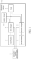
- FIG. 1 is a functional block diagram of a power management system according to one embodiment of the present invention.
- the power management system is adapted to an electronic device E.
- the power management system includes an alternative current (AC) power supply 1, a first battery 2, a first charger 3, a second battery 4, a second charger 5, and a control circuit 6.
- the first charger 3 is electrically connected to the first battery 2, a load L of the electronic device E, the alternative current power supply 1, and the control circuit 6.
- the load L includes electronic components that require electrical energy in the electronic device E, such as a central processing unit, a graphics processor, and a memory. When tasks processed by the electronic device E become more complex and require more system resources, power consumption of the load L is increased.
- settings of the central processing unit may include a first power limit PL1, a second power limit PL2, a third power limit PL3, a fourth power limit PL4, and other power consumption levels.
- the first power limit PL1 usually represents thermal design power consumption
- the second power limit PL2 represents short-term power consumption, which is suitable for a full load operation or overclocking at a turbo boost frequency.
- the second power limit PL2 is maximum power consumption when the central processing unit operates at a high clock speed, so that the second power limit PL2 is usually greater than the first power limit PL 1.
- the third power limit PL3 and the fourth power limit PL4 are modes with relatively higher power consumption.
- the second charger 5 is electrically connected to the second battery 4, the load L of the electronic device E, the AC power supply 1, and the control circuit 6.
- the first charger 3 can have a first system power, and the first system power is a first stopping threshold (e.g., in watts) that prohibits the AC power supply 1 from continuing to charge the first battery 2.
- the first system power is a first stopping threshold (e.g., in watts) that prohibits the AC power supply 1 from continuing to charge the first battery 2.
- the second charger 5 can have a second system power, and the second system power is a second stopping threshold (e.g., in watts) that prohibits the AC power supply 1 from continuing to charge the second battery 4.
- the AC power supply 1 is prohibited from continuing to charge the second battery 4.
- the control circuit 6 can be implemented by, for example, a micro control unit, a system on a chip, a programmable logic array, or a field programmable logic array.
- the control circuit 6 is electrically connected to the first charger 3 and the second charger 5.
- the control circuit 6 is configured to detect a capacity of the first battery 2 and a capacity of the second battery 4, so as to set the first system power of the first charger 3 and the second system power of the second charger 5.
- the control circuit 6 sets the first system power of the first charger 3 as a first rated power
- the control circuit 6 sets the second system power of the second charger 5 to be lower than the first rated power. Under this condition, there can be a difference between the first system power and the second system power.
- the difference may be greater than or equal to 5 watts.
- the AC power supply 1 is first prohibited from continuing to charge the second battery 4. Then, a turbo boost mode of the first charger 3 is enabled by the control circuit 6, so that the AC power supply 1 and the first battery 2 simultaneously supply power to the load L.
- the first system power of the first charger 3 should be slightly less than a rated power of the AC power supply 1. If the first system power is equal to the rated power of the AC power supply 1 and an error of the first charger 3 occurs, the first system power may exceed the rated power of the AC power supply 1 during a charging process, thereby failing to comply with a safety regulation.
- the first charger 3 and the second charger 5 can both operate in a turbo boost mode, so as to allow the AC power supply 1 and batteries that correspond to the first charger 3 and the second charger 5 to simultaneously supply power to the load L.
- the control circuit 6 disables the turbo boost mode of the second charger 5 while enabling the turbo boost mode of the first charger 3.
- the turbo boost mode of the first charger 3 is enabled, the first charger 3 allows the first battery 2 and the AC power supply 1 to simultaneously supply power to the load L of the electronic device E.
- the turbo boost mode of the second charger 5 is disabled, the second charger 5 only allows the AC power supply 1 to provide power to the load L of the electronic device E.
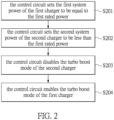
- FIG. 2 is a flowchart of a power management method that is adapted to the power management system of FIG. 1 according to a first embodiment of the present invention.
- the control circuit 6 sets the first system power of the first charger 3 to be equal to the first rated power.
- the control circuit 6 sets the second system power of the second charger 5 to be less than the first rated power.
- the control circuit 6 disables the turbo boost mode of the second charger 5.
- the control circuit 6 enables the turbo boost mode of the first charger 3.
- the control circuit 6 disables the turbo boost mode of the second charger 5.
- the control circuit 6 enables the turbo boost mode of the first charger 3, so that the AC power supply 1 and the first battery 2 simultaneously supply power to the load L.
- the AC power supply 1 does not continue to charge the first battery 2 and the second battery 4, so that the load L can obtain stable power for operation.
- FIG. 3 is a flowchart of the power management method that is adapted to the power management system of FIG. 1 according to a second embodiment of the present invention.
- the control circuit 6 sets the second system power of the second charger 5 to be equal to the first rated power.
- the control circuit 6 sets the first system power of the first charger 3 to be less than the first rated power.
- the control circuit 6 disables the turbo boost mode of the first charger 3.
- the control circuit 6 enables the turbo boost mode of the second charger 5.
- the control circuit 6 disables the turbo boost mode of the first charger 3.
- the control circuit 6 enables the turbo boost mode of the second charger 5, so that the AC power supply 1 and the second battery 5 simultaneously provide power to the load L.
- the AC power supply 1 does not continue to charge the first battery 2 and the second battery 4, so that the load L can obtain stable power for operation.
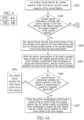
- FIGS. 4A and 4B are flowcharts of the power management method that is adapted to the power management system of FIG. 1 according to a third embodiment of the present invention.
- the control circuit 6 detects the current capacity of the first battery 2 and the current capacity of the second battery 4.
- the control circuit 6 determines whether the current capacity of the first battery 2 is less than or equal to the current capacity of the second battery 4.
- step S402 is followed by step S403.
- step S402 is followed by S404.
- step S403 the control circuit 6 sets the first system power of the first charger 3 to be equal to the first rated power, and sets the second system power of the second charger 5 to be lower than the first rated power.
- control circuit 6 sets the first system power of the first charger 3 by modifying a register of the first charger 3, and sets the second system power of the second charger 5 by modifying a register of the second charger 5.
- step S404 the control circuit 6 sets the second system power of the second charger 5 to be equal to the first rated power, and sets the first system power of the first charger 3 to be less than the first rated power.
- step S403 is followed by step S405.
- step S405 when the power consumption of the load L is greater than or equal to the second system power, the AC power supply 1 is prohibited from continuing to charge the second battery 4, and the control circuit 6 disables the turbo boost mode of the second charger 5.
- step S405 is followed by step S406.
- the control circuit 6 determines whether the current capacity of the first battery 2 is greater than or equal to a capacity threshold (e.g., 10%). When the current capacity of the first battery 2 is greater than or equal to the capacity threshold, step S406 is followed by step S407. When the current capacity of the first battery 2 is less than the capacity threshold, step S406 is followed by step S408.
- step S407 when the power consumption of the load L is greater than or equal to the first system power, the AC power supply 1 is prohibited from continuing to charge the first battery 2, and the control circuit 6 enables the turbo boost mode of the first charger 3.
- step S408 the control circuit 6 disables the turbo boost mode of the first charger 3.
- step S404 is followed by step S409.
- step S409 when the power consumption of the load L is greater than or equal to the first system power, the AC power supply 1 is prohibited from continuing to charge the first battery 2, and the control circuit 6 disables the turbo boost mode of the first charger 3.
- the first charger 3 When the first charger 3 does not enter the turbo boost mode, the first charger 3 only allows the AC power supply 1 to supply power to the load L of the electronic device E.
- step S410 the control circuit 6 determines whether the current capacity of the second battery 4 is greater than or equal to the capacity threshold. When the current capacity of the second battery 4 is greater than or equal to the capacity threshold, step S410 is followed by step S411. When the current capacity of the second battery 4 is less than the capacity threshold, step S410 is followed by step S412. In step S411, when the power consumption of the load L is greater than or equal to the second system power, the AC power supply 1 is prohibited from continuing to charge the second battery 4, and the control circuit 6 enables the turbo boost mode of the second charger 5. When the second charger 5 enters the turbo boost mode, the second charger 5 allows the second battery 4 and the AC power supply 1 to simultaneously supply power to the load L of the electronic device E.
- step S412 the control circuit 6 disables the turbo boost mode of the second charger 5.
- the second charger 5 does not enter the turbo boost mode, the second charger 5 only allows the AC power supply 1 to supply power to the load L of the electronic device E.
- the difference between the third embodiment of the power management method shown in FIGS. 4A and 4B and the first embodiment of the power management method shown in FIG. 2 is as follows.
- one of the first battery 2 and the second battery 4 with the lower capacity is charged by a large current
- another one of the first battery 2 and the second battery 4 with the higher capacity is charged by a small current. In this way, the charging time can be shortened.
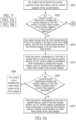
- FIGS. 5A and 5B are flowcharts of the power management method that is adapted to the power management system of FIG. 1 according to a fourth embodiment of the present invention.
- step S501 the control circuit 6 detects the current capacity of the first battery 2 and the current capacity of the second battery 4.
- step S502 the control circuit 6 determines whether the current capacity of the first battery 2 is greater than or equal to the current capacity of the second battery 4.
- step S503 When the current capacity of the first battery 2 is greater than or equal to the current capacity of the second battery 4, step S502 is followed by step S503.
- step S502 is followed by step S504.
- step S503 the control circuit 6 sets the first system power of the first charger 3 to be equal to the first rated power, and sets the second system power of the second charger 5 to be less than the first rated power.
- step S504 the control circuit 6 sets the second system power of the second charger 5 to be equal to the first rated power, and sets the first system power of the first charger 3 to be less than the first rated power.
- step S503 is followed by step S505.
- step S505 when the power consumption of the load L is greater than or equal to the second system power, the AC power supply 1 is prohibited from continuing to charge the second battery 4, and the control circuit 6 disables the turbo boost mode of the second charger 5.
- step S505 is followed by step S506.
- the control circuit 6 determines whether the current capacity of the first battery 2 is greater than or equal to the capacity threshold. When the current capacity of the first battery 2 is greater than or equal to the capacity threshold, step S506 is followed by step S507. When the current capacity of the first battery 2 is less than the capacity threshold, step S506 is followed by step S508.
- step S507 when the power consumption of the load L is greater than or equal to the first system power, the AC power supply 1 is prohibited from continuing to charge the first battery 2, and the control circuit 6 enables the turbo boost mode of the first charger 3.
- step S508 the control circuit 6 disables the turbo boost mode of the first charger 3.
- step S504 is followed by step S509.
- step S509 when the power consumption of the load L is greater than or equal to the first system power, the AC power supply 1 is prohibited from continuing to charge the first battery 2, and the control circuit 6 disables the turbo boost mode of the first charger 3.
- step S509 is followed by step S510.
- the control circuit 6 determines whether the current capacity of the second battery 4 is greater than or equal to the capacity threshold. When the current capacity of the second battery 4 is greater than or equal to the capacity threshold, step S510 is followed by step S511. When the current capacity of the second battery 4 is less than the capacity threshold, step S510 is followed by step S512.
- step S511 when the power consumption of the load L is greater than or equal to the second system power, the AC power supply 1 is prohibited from continuing to charge the second battery 4, and the control circuit 6 enables the turbo boost mode of the second charger 5.
- step S512 the control circuit 6 disables the turbo boost mode of the second charger 5.
- the AC power supply 1 does not continue to charge the first battery 3 and the second battery 5, so that the load L can obtain stable power for operation.
- the charger in the turbo boost mode is connected to a battery with a lower capacity
- the battery with the lower capacity is charged with a larger current
- the other battery with a higher capacity is charged with a smaller current, so that the charging time can be decreased.
- the charger in the turbo boost mode is connected to a battery with a higher capacity
- the battery with the higher capacity provides power to the load, so that the load can obtain sufficient power.
- the AC power supply 1 does not charge the battery. Therefore, even if the first power limit PL1, the second power limit PL2, and the fourth power limit PL4 of the central processing unit are not reduced, the central processing unit can still obtain stable power for operation, thereby optimizing the system performance of the electronic device E.
Landscapes
- Engineering & Computer Science (AREA)
- Power Engineering (AREA)
- Manufacturing & Machinery (AREA)
- Chemical & Material Sciences (AREA)
- Chemical Kinetics & Catalysis (AREA)
- Electrochemistry (AREA)
- General Chemical & Material Sciences (AREA)
- Charge And Discharge Circuits For Batteries Or The Like (AREA)
Abstract
Description
- The present invention relates to a power management system and a power management method, and more particularly to a power management system and a power management method that support a turbo boost mode.
- Conventionally, only one charger and one battery are disposed in an interior of a computer device. When power consumption of the computer device exceeds a rated power of an alternative current power supply, a control circuit enables a turbo boost mode of the charger. When the power consumption of the computer device does not exceed the rated power of the alternative current power supply, the control circuit disables the turbo boost mode of the charger.
- Since the computer device only supports the turbo boost mode of the single charger, a charging speed of the battery for an electronic device is limited.
- In response to the above-referenced technical inadequacies, the present invention provides a power management system and a power management method.
- In order to solve the above-mentioned problems, one of the technical aspects adopted by the present invention is to provide a power management system. The power management system is adapted to an electronic device, and includes an alternative current power supply, a first battery, a first charger, a second battery, a second charger, and a control circuit. The first charger is electrically connected to the first battery, the electronic device, and the alternative current power supply. The second charger is electrically connected to the second battery, the electronic device, and the alternative current power supply. The control circuit is electrically connected to the first charger and the second charger. The control circuit is configured to detect capacities of the first battery and the second battery, to set a first system power of the first charger as a first rated power, and to set a second system power of the second charger to be the second charger to be lower than the first rated power. The control circuit enables a turbo boost mode of the first charger and disables a turbo boost mode of the second charger.
- In order to solve the above-mentioned problems, another one of the technical aspects adopted by the present invention is to provide a power management method. The power management method is adapted to an electronic device, and includes configuring a control circuit to perform processes: setting a first system power of a first charger to be equal to a first rated power; setting a second system power of a second charger to be less than the first rated power; enabling a turbo boost mode of the first charger; and disabling a turbo boost mode of the second charger.
- Therefore, in the power management system and the power management method provided by the present invention, when the turbo boost mode of the first charger is enabled, the alternative current power supply does not continue to charge the first battery and the second battery, so that a load can obtain stable power for operation.
- The aspects of the present invention will become apparent from the following description of the embodiment taken in conjunction with the following drawings and their captions, although variations and modifications therein may be affected without departing from the spirit and scope of the novel concepts of the invention.
- The described embodiments may be better understood by reference to the following description and the accompanying drawings, in which:
-
FIG. 1 is a functional block diagram of a power management system according to one embodiment of the present invention; -
FIG. 2 is a flowchart of a power management method that is adapted to the power management system ofFIG. 1 according to a first embodiment of the present invention; -
FIG. 3 is a flowchart of the power management method that is adapted to the power management system ofFIG. 1 according to a second embodiment of the present invention; -
FIGS. 4A and4B are flowcharts of the power management method that is adapted to the power management system ofFIG. 1 according to a third embodiment of the present invention; and -
FIGS. 5A and5B are flowcharts of the power management method that is adapted to the power management system ofFIG. 1 according to a fourth embodiment of the present invention. - The present invention is more particularly described in the following examples that are intended as illustrative only since numerous modifications and variations therein will be apparent to those skilled in the art. Like numbers in the drawings indicate like components throughout the views. As used in the description herein and throughout the claims that follow, unless the context clearly dictates otherwise, the meaning of "a," "an" and "the" includes plural reference, and the meaning of "in" includes "in" and "on." Titles or subtitles can be used herein for the convenience of a reader, which shall have no influence on the scope of the present invention.
- The terms used herein generally have their ordinary meanings in the art. In the case of conflict, the present document, including any definitions given herein, will prevail. The same thing can be expressed in more than one way. Alternative language and synonyms can be used for any term(s) discussed herein, and no special significance is to be placed upon whether a term is elaborated or discussed herein. A recital of one or more synonyms does not exclude the use of other synonyms. The use of examples anywhere in this specification including examples of any terms is illustrative only, and in no way limits the scope and meaning of the present invention or of any exemplified term. Likewise, the present invention is not limited to various embodiments given herein. Numbering terms such as "first," "second" or "third" can be used to describe various components, signals or the like, which are for distinguishing one component/signal from another one only, and are not intended to, nor should be construed to impose any substantive limitations on the components, signals or the like.
-
FIG. 1 is a functional block diagram of a power management system according to one embodiment of the present invention. Referring toFIG. 1 , the power management system is adapted to an electronic device E. The power management system includes an alternative current (AC) power supply 1, a first battery 2, afirst charger 3, asecond battery 4, asecond charger 5, and acontrol circuit 6. Thefirst charger 3 is electrically connected to the first battery 2, a load L of the electronic device E, the alternative current power supply 1, and thecontrol circuit 6. The load L includes electronic components that require electrical energy in the electronic device E, such as a central processing unit, a graphics processor, and a memory. When tasks processed by the electronic device E become more complex and require more system resources, power consumption of the load L is increased. For example, settings of the central processing unit (CPU) may include a first power limit PL1, a second power limit PL2, a third power limit PL3, a fourth power limit PL4, and other power consumption levels. Here, the first power limit PL1 usually represents thermal design power consumption, and the second power limit PL2 represents short-term power consumption, which is suitable for a full load operation or overclocking at a turbo boost frequency. The second power limit PL2 is maximum power consumption when the central processing unit operates at a high clock speed, so that the second power limit PL2 is usually greater than the first power limit PL 1. The third power limit PL3 and the fourth power limit PL4 are modes with relatively higher power consumption. - In addition, the
second charger 5 is electrically connected to thesecond battery 4, the load L of the electronic device E, the AC power supply 1, and thecontrol circuit 6. Thefirst charger 3 can have a first system power, and the first system power is a first stopping threshold (e.g., in watts) that prohibits the AC power supply 1 from continuing to charge the first battery 2. Specifically, when the power consumption of the load L is greater than or equal to the first system power, the AC power supply 1 is prohibited from continuing to charge the first battery 2. Similarly, thesecond charger 5 can have a second system power, and the second system power is a second stopping threshold (e.g., in watts) that prohibits the AC power supply 1 from continuing to charge thesecond battery 4. When the power consumption of the load L is greater than or equal to the second system power, the AC power supply 1 is prohibited from continuing to charge thesecond battery 4. - The
control circuit 6 can be implemented by, for example, a micro control unit, a system on a chip, a programmable logic array, or a field programmable logic array. Thecontrol circuit 6 is electrically connected to thefirst charger 3 and thesecond charger 5. Thecontrol circuit 6 is configured to detect a capacity of the first battery 2 and a capacity of thesecond battery 4, so as to set the first system power of thefirst charger 3 and the second system power of thesecond charger 5. For example, thecontrol circuit 6 sets the first system power of thefirst charger 3 as a first rated power, and thecontrol circuit 6 sets the second system power of thesecond charger 5 to be lower than the first rated power. Under this condition, there can be a difference between the first system power and the second system power. For example, the difference may be greater than or equal to 5 watts. When the power consumption of the load L increases with time, the AC power supply 1 is first prohibited from continuing to charge thesecond battery 4. Then, a turbo boost mode of thefirst charger 3 is enabled by thecontrol circuit 6, so that the AC power supply 1 and the first battery 2 simultaneously supply power to the load L. - In addition, the first system power of the
first charger 3 should be slightly less than a rated power of the AC power supply 1. If the first system power is equal to the rated power of the AC power supply 1 and an error of thefirst charger 3 occurs, the first system power may exceed the rated power of the AC power supply 1 during a charging process, thereby failing to comply with a safety regulation. - In some embodiments, the
first charger 3 and thesecond charger 5 can both operate in a turbo boost mode, so as to allow the AC power supply 1 and batteries that correspond to thefirst charger 3 and thesecond charger 5 to simultaneously supply power to the load L. In detail, thecontrol circuit 6 disables the turbo boost mode of thesecond charger 5 while enabling the turbo boost mode of thefirst charger 3. When the turbo boost mode of thefirst charger 3 is enabled, thefirst charger 3 allows the first battery 2 and the AC power supply 1 to simultaneously supply power to the load L of the electronic device E. When the turbo boost mode of thesecond charger 5 is disabled, thesecond charger 5 only allows the AC power supply 1 to provide power to the load L of the electronic device E. -
FIG. 2 is a flowchart of a power management method that is adapted to the power management system ofFIG. 1 according to a first embodiment of the present invention. Referring toFIG. 2 , in step S201, thecontrol circuit 6 sets the first system power of thefirst charger 3 to be equal to the first rated power. In step S202, thecontrol circuit 6 sets the second system power of thesecond charger 5 to be less than the first rated power. In step S203, thecontrol circuit 6 disables the turbo boost mode of thesecond charger 5. In step S204, thecontrol circuit 6 enables the turbo boost mode of thefirst charger 3. Specifically, since the second system power is less than the first system power, the power consumption of the load L first rises to the second system power of thesecond charger 5, and the AC power supply 1 is prohibited from continuing to charge thesecond battery 4. Furthermore, thecontrol circuit 6 disables the turbo boost mode of thesecond charger 5. When the power consumption of the load L rises to the first system power of thefirst charger 3, the AC power supply 1 is prohibited from continuing to charge the first battery 2, and thecontrol circuit 6 enables the turbo boost mode of thefirst charger 3, so that the AC power supply 1 and the first battery 2 simultaneously supply power to the load L. - Through the power management method of
FIG. 2 , when the turbo boost mode of thefirst charger 3 is enabled by thecontrol circuit 6, the AC power supply 1 does not continue to charge the first battery 2 and thesecond battery 4, so that the load L can obtain stable power for operation. -
FIG. 3 is a flowchart of the power management method that is adapted to the power management system ofFIG. 1 according to a second embodiment of the present invention. Referring toFIG. 3 , in step S301, thecontrol circuit 6 sets the second system power of thesecond charger 5 to be equal to the first rated power. In step S302, thecontrol circuit 6 sets the first system power of thefirst charger 3 to be less than the first rated power. In step S303, thecontrol circuit 6 disables the turbo boost mode of thefirst charger 3. In step S304, thecontrol circuit 6 enables the turbo boost mode of thesecond charger 5. - Specifically, since the first system power is smaller than the second system power, the power consumption of the load L first rises to the first system power, and the AC power supply 1 is prohibited from continuing to charge the first battery 2. Furthermore, the
control circuit 6 disables the turbo boost mode of thefirst charger 3. When the power consumption of the load L rises to the second system power, the AC power supply 1 is prohibited from continuing to charge thesecond battery 4, and thecontrol circuit 6 enables the turbo boost mode of thesecond charger 5, so that the AC power supply 1 and thesecond battery 5 simultaneously provide power to the load L. - Through the power management method of
FIG. 3 , when the turbo boost mode of thesecond charger 5 is enabled, the AC power supply 1 does not continue to charge the first battery 2 and thesecond battery 4, so that the load L can obtain stable power for operation. -
FIGS. 4A and4B are flowcharts of the power management method that is adapted to the power management system ofFIG. 1 according to a third embodiment of the present invention. Referring toFIG. 4A , in step S401, thecontrol circuit 6 detects the current capacity of the first battery 2 and the current capacity of thesecond battery 4. In step S402, thecontrol circuit 6 determines whether the current capacity of the first battery 2 is less than or equal to the current capacity of thesecond battery 4. When the current capacity of the first battery 2 is less than or equal to the current capacity of thesecond battery 4, step S402 is followed by step S403. When the current capacity of the first battery 2 is greater than the current capacity of thesecond battery 4, step S402 is followed by S404. - Referring to
FIG. 4A , in step S403, thecontrol circuit 6 sets the first system power of thefirst charger 3 to be equal to the first rated power, and sets the second system power of thesecond charger 5 to be lower than the first rated power. - Specifically, the
control circuit 6 sets the first system power of thefirst charger 3 by modifying a register of thefirst charger 3, and sets the second system power of thesecond charger 5 by modifying a register of thesecond charger 5. - Referring to
FIG. 4B , in step S404, thecontrol circuit 6 sets the second system power of thesecond charger 5 to be equal to the first rated power, and sets the first system power of thefirst charger 3 to be less than the first rated power. - Referring to
FIG. 4A , step S403 is followed by step S405. In step S405, when the power consumption of the load L is greater than or equal to the second system power, the AC power supply 1 is prohibited from continuing to charge thesecond battery 4, and thecontrol circuit 6 disables the turbo boost mode of thesecond charger 5. - Referring to
FIG. 4A , step S405 is followed by step S406. In step S406, thecontrol circuit 6 determines whether the current capacity of the first battery 2 is greater than or equal to a capacity threshold (e.g., 10%). When the current capacity of the first battery 2 is greater than or equal to the capacity threshold, step S406 is followed by step S407. When the current capacity of the first battery 2 is less than the capacity threshold, step S406 is followed by step S408. In step S407, when the power consumption of the load L is greater than or equal to the first system power, the AC power supply 1 is prohibited from continuing to charge the first battery 2, and thecontrol circuit 6 enables the turbo boost mode of thefirst charger 3. In step S408, thecontrol circuit 6 disables the turbo boost mode of thefirst charger 3. - Referring to
FIG. 4B , step S404 is followed by step S409. In step S409, when the power consumption of the load L is greater than or equal to the first system power, the AC power supply 1 is prohibited from continuing to charge the first battery 2, and thecontrol circuit 6 disables the turbo boost mode of thefirst charger 3. When thefirst charger 3 does not enter the turbo boost mode, thefirst charger 3 only allows the AC power supply 1 to supply power to the load L of the electronic device E. - Referring to
FIG. 4B , step S409 is followed by step S410. In step S410, thecontrol circuit 6 determines whether the current capacity of thesecond battery 4 is greater than or equal to the capacity threshold. When the current capacity of thesecond battery 4 is greater than or equal to the capacity threshold, step S410 is followed by step S411. When the current capacity of thesecond battery 4 is less than the capacity threshold, step S410 is followed by step S412. In step S411, when the power consumption of the load L is greater than or equal to the second system power, the AC power supply 1 is prohibited from continuing to charge thesecond battery 4, and thecontrol circuit 6 enables the turbo boost mode of thesecond charger 5. When thesecond charger 5 enters the turbo boost mode, thesecond charger 5 allows thesecond battery 4 and the AC power supply 1 to simultaneously supply power to the load L of the electronic device E. - In step S412, the
control circuit 6 disables the turbo boost mode of thesecond charger 5. When thesecond charger 5 does not enter the turbo boost mode, thesecond charger 5 only allows the AC power supply 1 to supply power to the load L of the electronic device E. - The difference between the third embodiment of the power management method shown in
FIGS. 4A and4B and the first embodiment of the power management method shown inFIG. 2 is as follows. In the third embodiment, one of the first battery 2 and thesecond battery 4 with the lower capacity is charged by a large current, and another one of the first battery 2 and thesecond battery 4 with the higher capacity is charged by a small current. In this way, the charging time can be shortened. -
FIGS. 5A and5B are flowcharts of the power management method that is adapted to the power management system ofFIG. 1 according to a fourth embodiment of the present invention. - Referring to
FIG. 5A , in step S501, thecontrol circuit 6 detects the current capacity of the first battery 2 and the current capacity of thesecond battery 4. In step S502, thecontrol circuit 6 determines whether the current capacity of the first battery 2 is greater than or equal to the current capacity of thesecond battery 4. When the current capacity of the first battery 2 is greater than or equal to the current capacity of thesecond battery 4, step S502 is followed by step S503. When the current capacity of the first battery 2 is less than the current capacity of thesecond battery 4, step S502 is followed by step S504. - Referring to
FIG. 5A , in step S503, thecontrol circuit 6 sets the first system power of thefirst charger 3 to be equal to the first rated power, and sets the second system power of thesecond charger 5 to be less than the first rated power. - Referring to
FIG. 5B , in step S504, thecontrol circuit 6 sets the second system power of thesecond charger 5 to be equal to the first rated power, and sets the first system power of thefirst charger 3 to be less than the first rated power. - Referring to
FIG. 5A , step S503 is followed by step S505. In step S505, when the power consumption of the load L is greater than or equal to the second system power, the AC power supply 1 is prohibited from continuing to charge thesecond battery 4, and thecontrol circuit 6 disables the turbo boost mode of thesecond charger 5. - Referring to
FIG. 5A , step S505 is followed by step S506. In step S506, thecontrol circuit 6 determines whether the current capacity of the first battery 2 is greater than or equal to the capacity threshold. When the current capacity of the first battery 2 is greater than or equal to the capacity threshold, step S506 is followed by step S507. When the current capacity of the first battery 2 is less than the capacity threshold, step S506 is followed by step S508. In step S507, when the power consumption of the load L is greater than or equal to the first system power, the AC power supply 1 is prohibited from continuing to charge the first battery 2, and thecontrol circuit 6 enables the turbo boost mode of thefirst charger 3. In step S508, thecontrol circuit 6 disables the turbo boost mode of thefirst charger 3. - Referring to
Fig. 5B , step S504 is followed by step S509. In step S509, when the power consumption of the load L is greater than or equal to the first system power, the AC power supply 1 is prohibited from continuing to charge the first battery 2, and thecontrol circuit 6 disables the turbo boost mode of thefirst charger 3. - Referring to
FIG. 5B , step S509 is followed by step S510. In step S510, thecontrol circuit 6 determines whether the current capacity of thesecond battery 4 is greater than or equal to the capacity threshold. When the current capacity of thesecond battery 4 is greater than or equal to the capacity threshold, step S510 is followed by step S511. When the current capacity of thesecond battery 4 is less than the capacity threshold, step S510 is followed by step S512. In step S511, when the power consumption of the load L is greater than or equal to the second system power, the AC power supply 1 is prohibited from continuing to charge thesecond battery 4, and thecontrol circuit 6 enables the turbo boost mode of thesecond charger 5. - In step S512, the
control circuit 6 disables the turbo boost mode of thesecond charger 5. - Comparing the fourth embodiment of the power management method shown in
FIGS. 5A and5B and the first embodiment of the power management method shown inFIG. 2 , it can be observed that in the fourth embodiment, one of the first battery 2 and thesecond battery 5 with the higher capacity and the AC power supply 1 simultaneously provide power to the load L of the electronic device E. - In conclusion, in the power management system and the power management method provided by the present invention, regardless of which turbo boost mode (of the
first charger 3 or the second charger 5) is enabled, the AC power supply 1 does not continue to charge thefirst battery 3 and thesecond battery 5, so that the load L can obtain stable power for operation. When the charger in the turbo boost mode is connected to a battery with a lower capacity, the battery with the lower capacity is charged with a larger current, and the other battery with a higher capacity is charged with a smaller current, so that the charging time can be decreased. When the charger in the turbo boost mode is connected to a battery with a higher capacity, the battery with the higher capacity provides power to the load, so that the load can obtain sufficient power. Regardless of which turbo boost mode (of thefirst charger 3 or the second charger 5) is enabled, the AC power supply 1 does not charge the battery. Therefore, even if the first power limit PL1, the second power limit PL2, and the fourth power limit PL4 of the central processing unit are not reduced, the central processing unit can still obtain stable power for operation, thereby optimizing the system performance of the electronic device E.
Claims (10)
- A power management system, which is adapted to an electronic device (E), the power management system characterized by comprising:an alternative current power supply (1);a first battery (2);a first charger (3) electrically connected to the first battery (2), the electronic device (E), and the alternative current power supply (1);a second battery (4);a second charger (5) electrically connected to the second battery (4), the electronic device (E), and the alternative current power supply (1); anda control circuit (6) electrically connected to the first charger (3) and the second charger (5), wherein the control circuit (6) is configured to detect capacities of the first battery (2) and the second battery (4), to set a first system power of the first charger (3) as a first rated power, and to set a second system power of the second charger (5) to be lower than the first rated power;wherein the control circuit (6) enables a turbo boost mode of the first charger (3) and disables a turbo boost mode of the second charger (5).
- The power management system according to claim 1, wherein when a current capacity of the first battery (2) is greater than or equal to a capacity threshold, the control circuit (6) is configured to enable the turbo boost mode of the first charger (3); wherein when the current capacity of the first battery (2) is less than the capacity threshold, the control circuit (6) is configured to disable the turbo boost mode of the first charger (3); wherein when the current capacity of the first battery (2) is lower than a current capacity of the second battery (4), the control circuit (6) is configured to disable the turbo boost mode of the second charger (5).
- The power management system according to claim 1, wherein when the first charger (3) enters the turbo boost mode, the first charger (3) allows the first battery (2) and the alternative current power supply (1) to simultaneously provide power to the electronic device (E); wherein when the first charger (3) does not enter the turbo boost mode, the first charger (3) allows the alternative current power supply (1) to provide power to the electronic device (E).
- The power management system according to claim 1, wherein when a current capacity of the first battery (2) is greater than a current capacity of the second battery (4), the control circuit (6) is configured to disable the turbo boost mode of the second charger (5); wherein when the current capacity of the first battery (2) is equal to the current capacity of the second battery (4), the control circuit (6) is further configured to enable the turbo boost mode of the first charger (3) or the turbo boost mode of the second charger (5).
- The power management system according to claim 1, wherein a difference between the first system power and the second system power is greater than or equal to 5 watts.
- A power management method, which is adapted to an electronic device, the power management method characterized by comprising:
configuring a control circuit (6) to perform following:setting a first system power of a first charger (3) to be equal to a first rated power;setting a second system power of a second charger (5) to be less than the first rated power;enabling a turbo boost mode of the first charger (3); anddisabling a turbo boost mode of the second charger (5). - The power management method according to claim 6, further comprising:detecting a current capacity of a first battery (2) connected to the first charger (3) and a current capacity of a second battery (4) connected to the second charger (5); andenabling the turbo boost mode of the first charger (3) when the current capacity of the first battery (2) is greater than or equal to a capacity threshold; and disabling the turbo boost mode of the first charger (3) when the current capacity of the first battery (2) is less than the capacity threshold.
- The power management method according to claim 6, further comprising:configuring the control circuit (6) to set the first system power to be equal to the first rated power; andsetting the second system power to be less than the first rated power when a current capacity of a first battery (2) connected to the first charger (3) is less than a current capacity of a second battery (4) connected to the second charger (5).
- The power management method according to claim 6, further comprising:configuring the control circuit (6) to set the first system power to be equal to the first rated power; andsetting the second system power to be less than the first rated power when a current capacity of a first battery (2) connected to the first charger (3) is greater than a current capacity of a second battery (4) connected to the second charger (5).
- The power management method according to claim 6, further comprising:configuring the first charger (3) to allow a first battery (2) connected to the first charger (3) and an alternative current power supply (1) to simultaneously provide power to the electronic device (E) when the first charger (3) enters the turbo boost mode; andconfiguring the first charger (3) to only allow the alternative current power supply (1) to provide the power to the electronic device (E) when the first charger (3) does not enter the turbo boost mode.
Applications Claiming Priority (1)
| Application Number | Priority Date | Filing Date | Title |
|---|---|---|---|
| CN202311021038.2A CN119496222A (en) | 2023-08-14 | 2023-08-14 | Power management system and power management method |
Publications (2)
| Publication Number | Publication Date |
|---|---|
| EP4510420A2 true EP4510420A2 (en) | 2025-02-19 |
| EP4510420A3 EP4510420A3 (en) | 2025-07-02 |
Family
ID=91759361
Family Applications (1)
| Application Number | Title | Priority Date | Filing Date |
|---|---|---|---|
| EP24185643.4A Pending EP4510420A3 (en) | 2023-08-14 | 2024-07-01 | Power management system and power management method |
Country Status (3)
| Country | Link |
|---|---|
| US (1) | US12483055B2 (en) |
| EP (1) | EP4510420A3 (en) |
| CN (1) | CN119496222A (en) |
Family Cites Families (10)
| Publication number | Priority date | Publication date | Assignee | Title |
|---|---|---|---|---|
| JP2007306647A (en) | 2006-05-09 | 2007-11-22 | Lenovo Singapore Pte Ltd | Power supply system and electronic equipment |
| US20110234151A1 (en) | 2010-03-26 | 2011-09-29 | Uan-Zo-Li Alexander B | Platform with power boost |
| TW201214919A (en) | 2010-09-24 | 2012-04-01 | Lite On Clean Energy Technology Corp | Hybrid battery module and battery management method |
| WO2014109789A1 (en) | 2013-01-08 | 2014-07-17 | Intel Corporation | Detachable computing system having dual batteries |
| TWI508413B (en) | 2014-04-15 | 2015-11-11 | 廣達電腦股份有限公司 | Computer system and its power management method |
| US10097021B2 (en) * | 2015-08-27 | 2018-10-09 | Kabushiki Kaisha Toshiba | Charging device and charging method |
| EP4160895B1 (en) | 2018-08-29 | 2024-07-31 | Huawei Digital Power Technologies Co., Ltd. | Wireless battery charging with improved efficiency |
| GB2607242B (en) | 2020-01-28 | 2025-04-30 | Noco Co | Jump starting device with enhanced (turbo) boost mode |
| US12278512B2 (en) | 2020-12-23 | 2025-04-15 | Intel Corporation | Multi load and multi battery system with sharing apparatuses |
| TWI790966B (en) | 2022-05-10 | 2023-01-21 | 茂達電子股份有限公司 | Switching charger for supplying stable power |
-
2023
- 2023-08-14 CN CN202311021038.2A patent/CN119496222A/en active Pending
-
2024
- 2024-06-19 US US18/747,631 patent/US12483055B2/en active Active
- 2024-07-01 EP EP24185643.4A patent/EP4510420A3/en active Pending
Also Published As
| Publication number | Publication date |
|---|---|
| CN119496222A (en) | 2025-02-21 |
| US20250062634A1 (en) | 2025-02-20 |
| EP4510420A3 (en) | 2025-07-02 |
| US12483055B2 (en) | 2025-11-25 |
Similar Documents
| Publication | Publication Date | Title |
|---|---|---|
| US9337661B2 (en) | Power management system and method | |
| JP4197189B2 (en) | Circuit for power supply and method of operation | |
| CN106992326B (en) | Charging control method and device and electronic equipment | |
| US20180351372A1 (en) | Dual battery mobile terminal and wireless charging system thereof | |
| US10686324B2 (en) | Electronic apparatus and charging method thereof | |
| EP2624401B1 (en) | Electronic apparatus and driving control method thereof | |
| US20140032952A1 (en) | Electronic apparatus and drive control method thereof | |
| CN101714766B (en) | Battery high temperature condition prevention and protection method and system | |
| US12051925B2 (en) | Charging control method of a battery pack for portable electronic devices | |
| JP7553793B2 (en) | Control device | |
| EP4435342A1 (en) | Method and apparatus for unit control and photovoltaic multi-unit air conditioning system | |
| EP4510420A2 (en) | Power management system and power management method | |
| US20190148955A1 (en) | Power supply device and power supply method | |
| WO2026011471A1 (en) | Device control method, inverter and computer-readable storage medium | |
| US12246440B2 (en) | Mobile robot, mobile manipulator, method for controlling mobile robot, and non-transitory computer readable medium | |
| US20250044855A1 (en) | Multi-battery electronic device and protection method thereof | |
| TWI854780B (en) | Power management system and power management method | |
| US11791639B2 (en) | Discharge control method of a battery pack for portable electronic devices | |
| US20250300468A1 (en) | Control method for energy storage power supply, energy storage power supply, and energy storage system | |
| JP6913754B2 (en) | Battery pack | |
| KR20260055227A (en) | Apparatus for controlling battery temperature in an electronic device and method for operating thereof, and storage medium | |
| KR20250106819A (en) | Method for controlling power system and propulsion system of ship by integration and power stabilization system of a ship | |
| JP2024101526A (en) | Smart Battery Temperature Compensation Method |
Legal Events
| Date | Code | Title | Description |
|---|---|---|---|
| PUAI | Public reference made under article 153(3) epc to a published international application that has entered the european phase |
Free format text: ORIGINAL CODE: 0009012 |
|
| STAA | Information on the status of an ep patent application or granted ep patent |
Free format text: STATUS: THE APPLICATION HAS BEEN PUBLISHED |
|
| AK | Designated contracting states |
Kind code of ref document: A2 Designated state(s): AL AT BE BG CH CY CZ DE DK EE ES FI FR GB GR HR HU IE IS IT LI LT LU LV MC ME MK MT NL NO PL PT RO RS SE SI SK SM TR |
|
| PUAL | Search report despatched |
Free format text: ORIGINAL CODE: 0009013 |
|
| AK | Designated contracting states |
Kind code of ref document: A3 Designated state(s): AL AT BE BG CH CY CZ DE DK EE ES FI FR GB GR HR HU IE IS IT LI LT LU LV MC ME MK MT NL NO PL PT RO RS SE SI SK SM TR |
|
| RIC1 | Information provided on ipc code assigned before grant |
Ipc: H02J 3/14 20060101ALI20250528BHEP Ipc: H02J 7/34 20060101ALI20250528BHEP Ipc: H02J 7/02 20160101ALI20250528BHEP Ipc: H02J 7/00 20060101AFI20250528BHEP |
|
| STAA | Information on the status of an ep patent application or granted ep patent |
Free format text: STATUS: REQUEST FOR EXAMINATION WAS MADE |
|
| 17P | Request for examination filed |
Effective date: 20251006 |