EP4510396A1 - Cable insertion device and connector manufacturing device - Google Patents
Cable insertion device and connector manufacturing device Download PDFInfo
- Publication number
- EP4510396A1 EP4510396A1 EP24194258.0A EP24194258A EP4510396A1 EP 4510396 A1 EP4510396 A1 EP 4510396A1 EP 24194258 A EP24194258 A EP 24194258A EP 4510396 A1 EP4510396 A1 EP 4510396A1
- Authority
- EP
- European Patent Office
- Prior art keywords
- block
- cable
- hole
- row
- insertion device
- Prior art date
- Legal status (The legal status is an assumption and is not a legal conclusion. Google has not performed a legal analysis and makes no representation as to the accuracy of the status listed.)
- Granted
Links
Images




Classifications
-
- H—ELECTRICITY
- H01—ELECTRIC ELEMENTS
- H01R—ELECTRICALLY-CONDUCTIVE CONNECTIONS; STRUCTURAL ASSOCIATIONS OF A PLURALITY OF MUTUALLY-INSULATED ELECTRICAL CONNECTING ELEMENTS; COUPLING DEVICES; CURRENT COLLECTORS
- H01R43/00—Apparatus or processes specially adapted for manufacturing, assembling, maintaining, or repairing of line connectors or current collectors or for joining electric conductors
- H01R43/04—Apparatus or processes specially adapted for manufacturing, assembling, maintaining, or repairing of line connectors or current collectors or for joining electric conductors for forming connections by deformation, e.g. crimping tool
- H01R43/048—Crimping apparatus or processes
- H01R43/052—Crimping apparatus or processes with wire-feeding mechanism
-
- H—ELECTRICITY
- H01—ELECTRIC ELEMENTS
- H01R—ELECTRICALLY-CONDUCTIVE CONNECTIONS; STRUCTURAL ASSOCIATIONS OF A PLURALITY OF MUTUALLY-INSULATED ELECTRICAL CONNECTING ELEMENTS; COUPLING DEVICES; CURRENT COLLECTORS
- H01R43/00—Apparatus or processes specially adapted for manufacturing, assembling, maintaining, or repairing of line connectors or current collectors or for joining electric conductors
- H01R43/04—Apparatus or processes specially adapted for manufacturing, assembling, maintaining, or repairing of line connectors or current collectors or for joining electric conductors for forming connections by deformation, e.g. crimping tool
- H01R43/048—Crimping apparatus or processes
-
- H—ELECTRICITY
- H01—ELECTRIC ELEMENTS
- H01R—ELECTRICALLY-CONDUCTIVE CONNECTIONS; STRUCTURAL ASSOCIATIONS OF A PLURALITY OF MUTUALLY-INSULATED ELECTRICAL CONNECTING ELEMENTS; COUPLING DEVICES; CURRENT COLLECTORS
- H01R43/00—Apparatus or processes specially adapted for manufacturing, assembling, maintaining, or repairing of line connectors or current collectors or for joining electric conductors
- H01R43/20—Apparatus or processes specially adapted for manufacturing, assembling, maintaining, or repairing of line connectors or current collectors or for joining electric conductors for assembling or disassembling contact members with insulating base, case or sleeve
Definitions
- the present invention relates to a cable insertion device and a connector manufacturing device comprising the cable insertion device.
- a connector typically includes a housing, a terminal, and a cable.
- the terminal is provided in the housing, and the cable is inserted into the housing.
- the terminal needs to be crimped onto the cable.
- a cable clamp is required to clamp and secure the cable. This will increase the installation steps of connector and reduce manufacturing efficiency.
- the present invention has been made to overcome or alleviate at least one aspect of the above mentioned disadvantages.
- a cable insertion device comprises of: a first block having opposite top and bottom surfaces in a vertical direction and opposite front and rear sides in a first horizontal direction; a second block which is assembled onto the top of the first block and its bottom surface is against the top surface of the first block; a third block which is assembled onto the front side of the first block; and a locking component which is clamped between the first block and the third block.
- a row of slots is formed on the top surface of the first block, a row of upper semicircular holes corresponding to the row of slots is formed on the bottom surface of the second block, and a row of lower semicircular holes corresponding to the row of slots is formed on the top surface of the third block;
- the upper semicircular hole and the lower semicircular hole are combined into a guide hole for guiding a cable into a cable hole of a connector housing;
- the locking component comprises a row of elastic cantilevers corresponding to the row of slots, the elastic cantilever extends into the slot and is adapted to rest against the cable inserted into the cable hole to prevent the inserted cable from being pulled out of the cable hole of the connector housing.
- the slot extends along the vertical direction and the first horizontal direction and runs through the first block in the first horizontal direction; the upper semicircular hole runs through the second block in the first horizontal direction and aligns with the corresponding slot in the vertical direction; the lower semicircular hole runs through the third block in the first horizontal direction and aligns with the corresponding slot in the first horizontal direction.
- the locking component further comprises a plate-shaped body, the row of elastic cantilevers is connected to the upper side edge of the plate-shaped body, and the plate-shaped body is clamped between the front side of the first block and the rear side of the third block.
- the elastic cantilever comprises of: a first arm, which extends in the vertical direction and one end of which is connected to the plate-shaped body; and a second arm which is connected to the other end of the first arm and extends obliquely into the corresponding slot.
- the end of the second arm is adapted to rest against the inserted cable to prevent the inserted cable from being pulled out of the cable hole of the connector housing.
- a row of unlocking holes corresponding to the row of slots is formed on the third block, so that the elastic cantilever can be pushed to the unlocking position separate from the inserted cable by an unlocking tool inserted through the unlocking hole, allowing the inserted cable to be pulled out of the cable hole of the connector housing.
- the row of unlocking holes is located below the row of lower semicircular holes, and the unlocking hole runs through the third block in the first horizontal direction and aligns with the corresponding slot in the first horizontal direction.
- a horizontal step surface is formed on the front side of the first block, and the bottom surfaces of the third block and the locking component are supported on the horizontal step surface to position the third block and the locking component in the vertical direction.
- connection holes are respectively formed in the first block, the third block, and the locking component and communicated with each other, so that the first block, the third block, and the locking component can be fastened together through a connecting member passing through the connection holes.
- the second block comprises: a main body having two opposite ends in a second horizontal direction perpendicular to the first horizontal direction; and connecting parts which are located at both ends of the main body and are rotatably connected to the first block.
- the row of upper semicircular holes is formed on the bottom surface of the main body.
- a first connecting hole is formed in the first block, and the first connecting hole runs through the first block along the second horizontal direction, and a second connecting hole corresponding to the first connecting hole is formed in the connecting part of the second block;
- the cable insertion device further includes a connecting shaft, which is rotatably installed into the first connecting hole and the second connecting hole to rotatably install the second block onto the first block.
- the cable insertion device further comprises a limiting shaft which is installed on the first block and runs through the first block along a second horizontal direction perpendicular to the first horizontal direction, the limiting shaft passes through the slot and is used to rest against the elastic cantilever of the locking component to prevent excessive deformation of the elastic cantilever.
- the elastic cantilever when the cable is not inserted, the elastic cantilever is in a natural state without force and does not come into contact with the limiting shaft; when the cable is inserted, the elastic cantilever is moved to a position in contact with the limiting shaft under the pushing force of the cable.
- the locking component further comprises a plate-shaped body, the row of elastic cantilevers are connected to the upper side edge of the plate-shaped body, and the plate-shaped body is clamped between the front side of the first block and the rear side of the third block.
- the elastic cantilever comprises of: a first arm, which extends in a vertical direction and one end of which is connected to the plate-shaped body; and a second arm which is connected to the other end of the first arm and extends obliquely into the corresponding slot. The end of the second arm is adapted to rest against the inserted cable to prevent the inserted cable from being pulled out of the cable hole of the connector housing.
- the limiting shaft when the cable is inserted, the limiting shaft is supported on a connecting portion between the first arm and the second arm.
- a connector manufacturing device comprises the above cable insertion device which is used to guide a cable into a cable hole in a connector housing.
- the cable insertion device is positioned on one side of the connector housing, and the guide hole of the cable insertion device is aligned with the cable hole of the connector housing; when the cable is inserted into the cable hole through the guide hole, the end of the elastic cantilever of the locking component is against the cable to prevent it from being pulled out of the cable hole of the connector housing.
- a locking component is provided in the cable insertion device to prevent the inserted cable from being pulled out. Therefore, there is no need to provide a cable clamp, which reduces the manufacturing steps of the connector and improves the manufacturing efficiency of the connector.
- a cable insertion device comprises of: a first block having opposite top and bottom surfaces in a vertical direction and opposite front and rear sides in a first horizontal direction; a second block which is assembled onto the top of the first block and its bottom surface is against the top surface of the first block; a third block which is assembled onto the front side of the first block; and a locking component which is clamped between the first block and the third block.
- a row of slots is formed on the top surface of the first block, a row of upper semicircular holes corresponding to the row of slots is formed on the bottom surface of the second block, and a row of lower semicircular holes corresponding to the row of slots is formed on the top surface of the third block;
- the upper semicircular hole and the lower semicircular hole are combined into a guide hole for guiding a cable into a cable hole of a connector housing;
- the locking component comprises a row of elastic cantilevers corresponding to the row of slots, the elastic cantilever extends into the slot and is adapted to rest against the cable inserted into the cable hole to prevent the inserted cable from being pulled out of the cable hole of the connector housing.
- the connector manufacturing device comprises the above cable insertion device which is used to guide a cable into a cable hole in a connector housing.
- the cable insertion device is positioned on one side of the connector housing, and the guide hole of the cable insertion device is aligned with the cable hole of the connector housing; when the cable is inserted into the cable hole through the guide hole, the end of the elastic cantilever of the locking component is against the cable to prevent it from being pulled out of the cable hole of the connector housing.
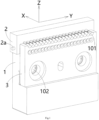
- Figure 1 shows an illustrative perspective view of a cable insertion device according to an exemplary embodiment of the present invention
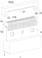
- Figure 2 shows an illustrative perspective view of a cable insertion device according to an exemplary embodiment of the present invention, where the second block 2 is not shown
- Figure 3 shows an illustrative sectional view of a cable insertion device according to an exemplary embodiment of the present invention
- Figure 4 shows an illustrative exploded view of a cable insertion device according to an exemplary embodiment of the present invention
- Figure 5 shows an illustrative perspective view of the first block 1 and second block 2 of the cable insertion device according to an exemplary embodiment of the present invention
- Figure 6 shows an illustrative perspective view of the first block 1 and the stopper 4 of the cable insertion device according to an exemplary embodiment of the present invention.
- a cable insertion device in an exemplary embodiment of the present invention, includes: a first block 1, a second block 2, a third block 3, and a locking component 4.
- the first block 1 has opposite top and bottom surfaces in the vertical direction Z, as well as opposite front and rear sides in the first horizontal direction X.
- the second block 2 is assembled to the top of the first block 1 and its bottom surface is against the top surface of the first block 1.
- the third block 3 is assembled to the front side of the first block 1.
- the locking component 4 is clamped between the first block 1 and the third block 3.
- Figure 7 shows a cross-sectional view of the cable insertion device and connector housing 5 according to an exemplary embodiment of the present invention
- Figure 8 shows an illustrative view of cable 6 inserted into the cable insertion device and connector housing 5 shown in Figure 7 .
- a row of slots 11 is formed on the top surface of the first block 1
- a row of upper semicircular holes 21 corresponding to the row of slots 11 is formed on the bottom surface of the second block 2
- a row of lower semicircular holes 31 corresponding to the row of slots 11 is formed on the top surface of the third block 3.
- the upper semicircular hole 21 and the lower semicircular hole 31 are combined into a guide hole 101 for guiding a cable 6 into a cable hole 51 of a connector housing 5.
- the locking component 4 includes a row of elastic cantilevers 41 corresponding to the row of slots 11.
- the elastic cantilever 41 extend into the slot 11 and is suitable to rest against the cable 6 inserted the cable hole 51 to prevent the inserted cable 6 from being pulled out of the cable hole 51 of the connector housing 5.
- the slot 11 extends along the vertical direction Z and the first horizontal direction X and runs through the first block 1 in the first horizontal direction X.
- the upper semicircular hole 21 runs through the second block 2 in the first horizontal direction X and aligns with the corresponding slot 11 in the vertical direction Z.
- the lower semicircular hole 31 runs through the third block 3 in the first horizontal direction X and aligns with the corresponding slot 11 in the first horizontal direction X.
- the locking member 4 further comprises a plate-shaped body 40, the row of elastic cantilevers 41 are connected to the upper side edge of the plate-shaped body 40, and the plate-shaped body 40 is clamped between the front side of the first block 1 and the rear side of the third block 3.
- the elastic cantilever 41 comprises a first arm portion 41a and a second arm portion 41b.
- One end of the first arm 41a is connected to the plate-shaped body 40 and extends in the vertical direction Z.
- the second arm 41b is connected to the other end of the first arm 41a and extends obliquely into the corresponding slot 11.
- the end of the second arm 41b is suitable for pressing against the inserted cable 6 to prevent the inserted cable 6 from being pulled out of the cable hole 51 of the connector housing 5.
- the second arm 41b is in a barbed shape, thus preventing the inserted cable 6 from being pulled out of the cable hole 51 of the connector housing 5.
- a row of unlocking holes 32 corresponding to the row of slots 11 are also formed on the third block 3, so that the elastic cantilever 41 can be pushed to the unlocking position separate from the inserted cable 6 by an unlocking tool (not shown) inserted through the unlocking hole 32, allowing the inserted cable 6 to be pulled out of the cable hole 51 of the connector housing 5.
- a row of unlocking holes 32 are located below the row of the lower semicircular holes 31, and the unlocking hole 32 runs through the third block 3 in the first horizontal direction X and aligns with the corresponding slot 11 in the first horizontal direction X.
- a horizontal step surface 1c is formed on the front side of the first block 1, and the bottom surfaces of the third block 3 and the locking component 4 are supported on the horizontal step surface 1c to locate the third block 3 and the locking component 4 in the vertical direction Z.
- connection holes 102 are respectively formed in the first block 1, the third block 3, and the locking component 4.
- the connection holes 102 are communicated with each other, so that the first block 1, the third block 3, and the locking component 4 can be fastened together through a connecting member (not shown, such as a bolt) that passes through the connection holes 102.
- the second block 2 comprises a main body 20 and two connecting parts 22.
- the main body 20 has two opposite ends in a second horizontal direction Y perpendicular to the first horizontal direction X.
- the connecting parts 22 are located at both ends of the main body 20 and are rotatably connected to the first block 1.
- the row of upper semicircular holes 21 are formed on the bottom surface of the main body 20.
- a first connecting hole 1a is formed on the first block 1, and the first connecting hole 1a runs through the first block 1 along the second horizontal direction Y
- a second connecting hole 2b corresponding to the first connecting hole 1a is formed on the connecting part 22 of the second block 2.
- the cable insertion device also includes a connecting shaft 2a, which is rotatably installed into the first connecting hole 1a and the second connecting hole 2b to rotatably install the second block 2 onto the first block 1.
- the cable insertion device further comprises a limiting shaft 1b, which is installed on the first block 1 and runs through the first block 1 in a second horizontal direction Y perpendicular to the first horizontal direction X.
- the limiting shaft 1b passes through the slot 11 and is used to rest against the elastic cantilever 41 of the locking component 4 to prevent excessive deformation of the elastic cantilever 41.
- the elastic cantilever 41 when the cable 6 is not inserted, the elastic cantilever 41 is in a natural state without force and does not contact the limiting shaft 1b. As shown in Figure 8 , in the illustrated embodiment, when the cable 6 is inserted, the elastic cantilever 41 is moved to the position in contact with the limiting shaft 1b under the pushing of the inserted cable 6.
- a connector manufacturing device is also disclosed.
- the connector manufacturing device includes the above cable insertion device for guiding a cable 6 into a cable hole 51 of a connector housing 5.
- the cable insertion device is positioned on one side of the connector housing 5, and the guide hole 101 of the cable insertion device is aligned with the cable hole 51 of the connector housing 5.
- the end of the elastic cantilever 41 of the locking component 4 is pressed against the inserted cable 6 to prevent the cable 6 from being pulled out of the cable hole 51 of the connector housing 5.
Landscapes
- Engineering & Computer Science (AREA)
- Manufacturing & Machinery (AREA)
- Details Of Connecting Devices For Male And Female Coupling (AREA)
- Manufacturing Of Electrical Connectors (AREA)
Abstract
Description
- This application claims the benefit of Chinese Patent Application No.
CN202311036673.8 filed on August 16, 2023 - The present invention relates to a cable insertion device and a connector manufacturing device comprising the cable insertion device.
- In the prior art, a connector typically includes a housing, a terminal, and a cable. The terminal is provided in the housing, and the cable is inserted into the housing. Usually, the terminal needs to be crimped onto the cable. To ensure that the cable remains stationary during crimping, a cable clamp is required to clamp and secure the cable. This will increase the installation steps of connector and reduce manufacturing efficiency.
- The present invention has been made to overcome or alleviate at least one aspect of the above mentioned disadvantages.
- According to an aspect of the present invention, there is provided a cable insertion device. The cable insertion device comprises of: a first block having opposite top and bottom surfaces in a vertical direction and opposite front and rear sides in a first horizontal direction; a second block which is assembled onto the top of the first block and its bottom surface is against the top surface of the first block; a third block which is assembled onto the front side of the first block; and a locking component which is clamped between the first block and the third block. A row of slots is formed on the top surface of the first block, a row of upper semicircular holes corresponding to the row of slots is formed on the bottom surface of the second block, and a row of lower semicircular holes corresponding to the row of slots is formed on the top surface of the third block; the upper semicircular hole and the lower semicircular hole are combined into a guide hole for guiding a cable into a cable hole of a connector housing; the locking component comprises a row of elastic cantilevers corresponding to the row of slots, the elastic cantilever extends into the slot and is adapted to rest against the cable inserted into the cable hole to prevent the inserted cable from being pulled out of the cable hole of the connector housing.
- According to another exemplary embodiment of the present invention, the slot extends along the vertical direction and the first horizontal direction and runs through the first block in the first horizontal direction; the upper semicircular hole runs through the second block in the first horizontal direction and aligns with the corresponding slot in the vertical direction; the lower semicircular hole runs through the third block in the first horizontal direction and aligns with the corresponding slot in the first horizontal direction.
- According to another exemplary embodiment of the present invention, the locking component further comprises a plate-shaped body, the row of elastic cantilevers is connected to the upper side edge of the plate-shaped body, and the plate-shaped body is clamped between the front side of the first block and the rear side of the third block.
- According to another exemplary embodiment of the present invention, the elastic cantilever comprises of: a first arm, which extends in the vertical direction and one end of which is connected to the plate-shaped body; and a second arm which is connected to the other end of the first arm and extends obliquely into the corresponding slot. The end of the second arm is adapted to rest against the inserted cable to prevent the inserted cable from being pulled out of the cable hole of the connector housing.
- According to another exemplary embodiment of the present invention, a row of unlocking holes corresponding to the row of slots is formed on the third block, so that the elastic cantilever can be pushed to the unlocking position separate from the inserted cable by an unlocking tool inserted through the unlocking hole, allowing the inserted cable to be pulled out of the cable hole of the connector housing.
- According to another exemplary embodiment of the present invention, the row of unlocking holes is located below the row of lower semicircular holes, and the unlocking hole runs through the third block in the first horizontal direction and aligns with the corresponding slot in the first horizontal direction.
- According to another exemplary embodiment of the present invention, a horizontal step surface is formed on the front side of the first block, and the bottom surfaces of the third block and the locking component are supported on the horizontal step surface to position the third block and the locking component in the vertical direction.
- According to another exemplary embodiment of the present invention, connection holes are respectively formed in the first block, the third block, and the locking component and communicated with each other, so that the first block, the third block, and the locking component can be fastened together through a connecting member passing through the connection holes.
- According to another exemplary embodiment of the present invention, the second block comprises: a main body having two opposite ends in a second horizontal direction perpendicular to the first horizontal direction; and connecting parts which are located at both ends of the main body and are rotatably connected to the first block. The row of upper semicircular holes is formed on the bottom surface of the main body.
- According to another exemplary embodiment of the present invention, a first connecting hole is formed in the first block, and the first connecting hole runs through the first block along the second horizontal direction, and a second connecting hole corresponding to the first connecting hole is formed in the connecting part of the second block; the cable insertion device further includes a connecting shaft, which is rotatably installed into the first connecting hole and the second connecting hole to rotatably install the second block onto the first block.
- According to another exemplary embodiment of the present invention, the cable insertion device further comprises a limiting shaft which is installed on the first block and runs through the first block along a second horizontal direction perpendicular to the first horizontal direction, the limiting shaft passes through the slot and is used to rest against the elastic cantilever of the locking component to prevent excessive deformation of the elastic cantilever.
- According to another exemplary embodiment of the present invention, when the cable is not inserted, the elastic cantilever is in a natural state without force and does not come into contact with the limiting shaft; when the cable is inserted, the elastic cantilever is moved to a position in contact with the limiting shaft under the pushing force of the cable.
- According to another exemplary embodiment of the present invention, the locking component further comprises a plate-shaped body, the row of elastic cantilevers are connected to the upper side edge of the plate-shaped body, and the plate-shaped body is clamped between the front side of the first block and the rear side of the third block. The elastic cantilever comprises of: a first arm, which extends in a vertical direction and one end of which is connected to the plate-shaped body; and a second arm which is connected to the other end of the first arm and extends obliquely into the corresponding slot. The end of the second arm is adapted to rest against the inserted cable to prevent the inserted cable from being pulled out of the cable hole of the connector housing.
- According to another exemplary embodiment of the present invention, when the cable is inserted, the limiting shaft is supported on a connecting portion between the first arm and the second arm.
- According to another aspect of the present invention, there is provided a connector manufacturing device. The connector manufacturing device comprises the above cable insertion device which is used to guide a cable into a cable hole in a connector housing. The cable insertion device is positioned on one side of the connector housing, and the guide hole of the cable insertion device is aligned with the cable hole of the connector housing; when the cable is inserted into the cable hole through the guide hole, the end of the elastic cantilever of the locking component is against the cable to prevent it from being pulled out of the cable hole of the connector housing.
- In the aforementioned exemplary embodiments of the present invention, a locking component is provided in the cable insertion device to prevent the inserted cable from being pulled out. Therefore, there is no need to provide a cable clamp, which reduces the manufacturing steps of the connector and improves the manufacturing efficiency of the connector.
- The above and other features of the present invention will become more apparent by describing in detail exemplary embodiments thereof with reference to the accompanying drawings, in which:
-
Figure 1 shows an illustrative perspective view of a cable insertion device according to an exemplary embodiment of the present invention; -
Figure 2 shows an illustrative perspective view of a cable insertion device according to an exemplary embodiment of the present invention, where a second block is not shown; -
Figure 3 shows an illustrative sectional view of a cable insertion device according to an exemplary embodiment of the present invention; -
Figure 4 shows an illustrative exploded view of a cable insertion device according to an exemplary embodiment of the present invention; -
Figure 5 shows an illustrative perspective view of the first and second blocks of the cable insertion device according to an exemplary embodiment of the present invention; -
Figure 6 shows an illustrative perspective view of the first block and locking component of the cable insertion device according to an exemplary embodiment of the present invention; -
Figure 7 shows a cross-sectional view of the cable insertion device and connector housing according to an exemplary embodiment of the present invention; and -
Figure 8 shows an illustrative view of the cable insertion device and connector housing shown inFigure 7 . - Exemplary embodiments of the present disclosure will be described hereinafter in detail with reference to the attached drawings, wherein the like reference numerals refer to the like elements. The present disclosure may, however, be embodied in many different forms and should not be construed as being limited to the embodiment set forth herein; rather, these embodiments are provided so that the present disclosure will be thorough and complete, and will fully convey the concept of the disclosure to those skilled in the art.
- In the following detailed description, for purposes of explanation, numerous specific details are set forth in order to provide a thorough understanding of the disclosed embodiments. It will be apparent, however, that one or more embodiments may be practiced without these specific details. In other instances, well-known structures and devices are schematically shown in order to simplify the drawing.
- According to a general concept of the present invention, there is provided a cable insertion device. The cable insertion device comprises of: a first block having opposite top and bottom surfaces in a vertical direction and opposite front and rear sides in a first horizontal direction; a second block which is assembled onto the top of the first block and its bottom surface is against the top surface of the first block; a third block which is assembled onto the front side of the first block; and a locking component which is clamped between the first block and the third block. A row of slots is formed on the top surface of the first block, a row of upper semicircular holes corresponding to the row of slots is formed on the bottom surface of the second block, and a row of lower semicircular holes corresponding to the row of slots is formed on the top surface of the third block; the upper semicircular hole and the lower semicircular hole are combined into a guide hole for guiding a cable into a cable hole of a connector housing; the locking component comprises a row of elastic cantilevers corresponding to the row of slots, the elastic cantilever extends into the slot and is adapted to rest against the cable inserted into the cable hole to prevent the inserted cable from being pulled out of the cable hole of the connector housing.
- According to another general concept of the present invention, there is provided a connector manufacturing device. The connector manufacturing device comprises the above cable insertion device which is used to guide a cable into a cable hole in a connector housing. The cable insertion device is positioned on one side of the connector housing, and the guide hole of the cable insertion device is aligned with the cable hole of the connector housing; when the cable is inserted into the cable hole through the guide hole, the end of the elastic cantilever of the locking component is against the cable to prevent it from being pulled out of the cable hole of the connector housing.
-
Figure 1 shows an illustrative perspective view of a cable insertion device according to an exemplary embodiment of the present invention;Figure 2 shows an illustrative perspective view of a cable insertion device according to an exemplary embodiment of the present invention, where thesecond block 2 is not shown;Figure 3 shows an illustrative sectional view of a cable insertion device according to an exemplary embodiment of the present invention;Figure 4 shows an illustrative exploded view of a cable insertion device according to an exemplary embodiment of the present invention;Figure 5 shows an illustrative perspective view of thefirst block 1 andsecond block 2 of the cable insertion device according to an exemplary embodiment of the present invention;Figure 6 shows an illustrative perspective view of thefirst block 1 and thestopper 4 of the cable insertion device according to an exemplary embodiment of the present invention. - As shown in
Figures 1 to 6 , in an exemplary embodiment of the present invention, a cable insertion device is disclosed. The cable insertion device includes: afirst block 1, asecond block 2, athird block 3, and alocking component 4. Thefirst block 1 has opposite top and bottom surfaces in the vertical direction Z, as well as opposite front and rear sides in the first horizontal direction X. Thesecond block 2 is assembled to the top of thefirst block 1 and its bottom surface is against the top surface of thefirst block 1. Thethird block 3 is assembled to the front side of thefirst block 1. Thelocking component 4 is clamped between thefirst block 1 and thethird block 3. -
Figure 7 shows a cross-sectional view of the cable insertion device andconnector housing 5 according to an exemplary embodiment of the present invention;Figure 8 shows an illustrative view ofcable 6 inserted into the cable insertion device andconnector housing 5 shown inFigure 7 . - As shown in
Figures 1 to 8 , in the illustrated embodiments, a row ofslots 11 is formed on the top surface of thefirst block 1, a row of uppersemicircular holes 21 corresponding to the row ofslots 11 is formed on the bottom surface of thesecond block 2, and a row of lowersemicircular holes 31 corresponding to the row ofslots 11 is formed on the top surface of thethird block 3. The uppersemicircular hole 21 and the lowersemicircular hole 31 are combined into aguide hole 101 for guiding acable 6 into acable hole 51 of aconnector housing 5. Thelocking component 4 includes a row ofelastic cantilevers 41 corresponding to the row ofslots 11. Theelastic cantilever 41 extend into theslot 11 and is suitable to rest against thecable 6 inserted thecable hole 51 to prevent the insertedcable 6 from being pulled out of thecable hole 51 of theconnector housing 5. - As shown in
Figures 1 to 8 , in the illustrated embodiments, theslot 11 extends along the vertical direction Z and the first horizontal direction X and runs through thefirst block 1 in the first horizontal direction X. The uppersemicircular hole 21 runs through thesecond block 2 in the first horizontal direction X and aligns with the correspondingslot 11 in the vertical direction Z. The lowersemicircular hole 31 runs through thethird block 3 in the first horizontal direction X and aligns with the correspondingslot 11 in the first horizontal direction X. - As shown in
Figures 1 to 8 , in the illustrated embodiments, the lockingmember 4 further comprises a plate-shapedbody 40, the row ofelastic cantilevers 41 are connected to the upper side edge of the plate-shapedbody 40, and the plate-shapedbody 40 is clamped between the front side of thefirst block 1 and the rear side of thethird block 3. - As shown in
Figures 1 to 8 , in the illustrated embodiments, theelastic cantilever 41 comprises afirst arm portion 41a and asecond arm portion 41b. One end of thefirst arm 41a is connected to the plate-shapedbody 40 and extends in the vertical direction Z. Thesecond arm 41b is connected to the other end of thefirst arm 41a and extends obliquely into the correspondingslot 11. The end of thesecond arm 41b is suitable for pressing against the insertedcable 6 to prevent the insertedcable 6 from being pulled out of thecable hole 51 of theconnector housing 5. In the illustrated embodiment, thesecond arm 41b is in a barbed shape, thus preventing the insertedcable 6 from being pulled out of thecable hole 51 of theconnector housing 5. - As shown in
Figures 1 to 8 , in the illustrated embodiments, a row of unlockingholes 32 corresponding to the row ofslots 11 are also formed on thethird block 3, so that theelastic cantilever 41 can be pushed to the unlocking position separate from the insertedcable 6 by an unlocking tool (not shown) inserted through the unlockinghole 32, allowing the insertedcable 6 to be pulled out of thecable hole 51 of theconnector housing 5. - As shown in
Figures 1 to 8 , in the illustrated embodiments, a row of unlockingholes 32 are located below the row of the lowersemicircular holes 31, and the unlockinghole 32 runs through thethird block 3 in the first horizontal direction X and aligns with the correspondingslot 11 in the first horizontal direction X. - As shown in
Figures 1 to 8 , in the illustrated embodiments, ahorizontal step surface 1c is formed on the front side of thefirst block 1, and the bottom surfaces of thethird block 3 and thelocking component 4 are supported on thehorizontal step surface 1c to locate thethird block 3 and thelocking component 4 in the vertical direction Z. - As shown in
Figures 1 to 8 , in the illustrated embodiments, connection holes 102 are respectively formed in thefirst block 1, thethird block 3, and thelocking component 4. The connection holes 102 are communicated with each other, so that thefirst block 1, thethird block 3, and thelocking component 4 can be fastened together through a connecting member (not shown, such as a bolt) that passes through the connection holes 102. - As shown in
Figures 1 to 8 , in the illustrated embodiment, thesecond block 2 comprises amain body 20 and two connectingparts 22. Themain body 20 has two opposite ends in a second horizontal direction Y perpendicular to the first horizontal direction X. The connectingparts 22 are located at both ends of themain body 20 and are rotatably connected to thefirst block 1. The row of uppersemicircular holes 21 are formed on the bottom surface of themain body 20. - As shown in
Figures 1 to 8 , in the illustrated embodiments, a first connectinghole 1a is formed on thefirst block 1, and the first connectinghole 1a runs through thefirst block 1 along the second horizontal direction Y A second connectinghole 2b corresponding to the first connectinghole 1a is formed on the connectingpart 22 of thesecond block 2. The cable insertion device also includes a connectingshaft 2a, which is rotatably installed into the first connectinghole 1a and the second connectinghole 2b to rotatably install thesecond block 2 onto thefirst block 1. - As shown in
Figures 1 to 8 , in the illustrated embodiments, the cable insertion device further comprises a limitingshaft 1b, which is installed on thefirst block 1 and runs through thefirst block 1 in a second horizontal direction Y perpendicular to the first horizontal direction X. The limitingshaft 1b passes through theslot 11 and is used to rest against theelastic cantilever 41 of thelocking component 4 to prevent excessive deformation of theelastic cantilever 41. - As shown in
Figure 7 , in the illustrated embodiment, when thecable 6 is not inserted, theelastic cantilever 41 is in a natural state without force and does not contact the limitingshaft 1b. As shown inFigure 8 , in the illustrated embodiment, when thecable 6 is inserted, theelastic cantilever 41 is moved to the position in contact with the limitingshaft 1b under the pushing of the insertedcable 6. - As shown in
Figures 1 to 8 , in the illustrated embodiments, when thecable 6 is inserted, the limitingshaft 1b is supported on the connection portion between thefirst arm 41a and thesecond arm 41b. - As shown in
Figures 1 to 8 , in another exemplary embodiment of the present invention, a connector manufacturing device is also disclosed. The connector manufacturing device includes the above cable insertion device for guiding acable 6 into acable hole 51 of aconnector housing 5. The cable insertion device is positioned on one side of theconnector housing 5, and theguide hole 101 of the cable insertion device is aligned with thecable hole 51 of theconnector housing 5. When thecable 6 is inserted into thecable hole 51 through theguide hole 101, the end of theelastic cantilever 41 of thelocking component 4 is pressed against the insertedcable 6 to prevent thecable 6 from being pulled out of thecable hole 51 of theconnector housing 5. - It should be appreciated for those skilled in this art that the above embodiments are intended to be illustrated, and not restrictive. For example, many modifications may be made to the above embodiments by those skilled in this art, and various features described in different embodiments may be freely combined with each other without conflicting in configuration or principle.
- Although several exemplary embodiments have been shown and described, it would be appreciated by those skilled in the art that various changes or modifications may be made in these embodiments without departing from the principles and spirit of the disclosure, the scope of which is defined in the claims and their equivalents.
- As used herein, an element recited in the singular and proceeded with the word "a" or "an" should be understood as not excluding plural of said elements or steps, unless such exclusion is explicitly stated. Furthermore, references to "one embodiment" of the present invention are not intended to be interpreted as excluding the existence of additional embodiments that also incorporate the recited features. Moreover, unless explicitly stated to the contrary, embodiments "comprising" or "having" an element or a plurality of elements having a particular property may include additional such elements not having that property.
Claims (15)
- A cable insertion device, comprising:a first block (1) having opposite top and bottom surfaces in a vertical direction (Z) and opposite front and rear sides in a first horizontal direction (X);a second block (2) which is assembled onto the top of the first block (1) and its bottom surface is against the top surface of the first block (1);a third block (3) which is assembled onto the front side of the first block (1); anda locking component (4) which is clamped between the first block (1) and the third block (3),wherein a row of slots (11) is formed on the top surface of the first block (1), a row of upper semicircular holes (21) corresponding to the row of slots (11) is formed on the bottom surface of the second block (2), and a row of lower semicircular holes (31) corresponding to the row of slots (11) is formed on the top surface of the third block (3),wherein the upper semicircular hole (21) and the lower semicircular hole (31) are combined into a guide hole (101) for guiding a cable (6) into a cable hole (51) of a connector housing (5),wherein the locking component (4) comprises a row of elastic cantilevers (41) corresponding to the row of slots (11), the elastic cantilever (41) extends into the slot (11) and is adapted to rest against the cable (6) inserted into the cable hole (51) to prevent the inserted cable (6) from being pulled out of the cable hole (51) of the connector housing (5).
- The cable insertion device according to claim 1,wherein the slot (11) extends along the vertical direction (Z) and the first horizontal direction (X) and runs through the first block (1) in the first horizontal direction (X);wherein the upper semicircular hole (21) runs through the second block (2) in the first horizontal direction (X) and aligns with the corresponding slot (11) in the vertical direction (Z);wherein the lower semicircular hole (31) runs through the third block (3) in the first horizontal direction (X) and aligns with the corresponding slot (11) in the first horizontal direction (X).
- The cable insertion device according to claim 1,
wherein the locking component (4) further comprises a plate-shaped body (40), the row of elastic cantilevers (41) is connected to the upper side edge of the plate-shaped body (40), and the plate-shaped body (40) is clamped between the front side of the first block (1) and the rear side of the third block (3). - The cable insertion device according to claim 3,wherein the elastic cantilever (41) comprises of:a first arm (41a), which extends in the vertical direction (Z) and one end of which is connected to the plate-shaped body (40); anda second arm (41b) which is connected to the other end of the first arm (41a) and extends obliquely into the corresponding slot (11),wherein the end of the second arm (41b) is adapted to rest against the inserted cable (6) to prevent the inserted cable (6) from being pulled out of the cable hole (51) of the connector housing (5).
- The cable insertion device according to claim 1,
wherein a row of unlocking holes (32) corresponding to the row of slots (11) is formed on the third block (3), so that the elastic cantilever (41) can be pushed to the unlocking position separate from the inserted cable (6) by an unlocking tool inserted through the unlocking hole (32), allowing the inserted cable (6) to be pulled out of the cable hole (51) of the connector housing (5). - The cable insertion device according to claim 5,
wherein the row of unlocking holes (32) is located below the row of lower semicircular holes (31), and the unlocking hole (32) runs through the third block (3) in the first horizontal direction (X) and aligns with the corresponding slot (11) in the first horizontal direction (X). - The cable insertion device according to claim 1,
wherein a horizontal step surface (1c) is formed on the front side of the first block (1), and the bottom surfaces of the third block (3) and the locking component (4) are supported on the horizontal step surface (1c) to position the third block (3) and the locking component (4) in the vertical direction (Z). - The cable insertion device according to claim 7,
wherein connection holes (102) are respectively formed in the first block (1), the third block (3), and the locking component (4) and communicated with each other, so that the first block (1), the third block (3), and the locking component (4) can be fastened together through a connecting member passing through the connection holes (102). - The cable insertion device according to claim 1,wherein the second block (2) comprises:a main body (20) having two opposite ends in a second horizontal direction (Y) perpendicular to the first horizontal direction (X); andconnecting parts (22) which are located at both ends of the main body (20) and are rotatably connected to the first block (1),wherein the row of upper semicircular holes (21) is formed on the bottom surface of the main body (20).
- The cable insertion device according to claim 9,wherein a first connecting hole (1a) is formed in the first block (1), and the first connecting hole (1a) runs through the first block (1) along the second horizontal direction (Y), and a second connecting hole (2b) corresponding to the first connecting hole (1a) is formed in the connecting part (22) of the second block (2);wherein the cable insertion device further includes a connecting shaft (2a), which is rotatably installed into the first connecting hole (1a) and the second connecting hole (2b) to rotatably install the second block (2) onto the first block (1).
- The cable insertion device according to claim 1, further comprising:a limiting shaft (1b) which is installed on the first block (1) and runs through the first block (1) along a second horizontal direction (Y) perpendicular to the first horizontal direction (X),wherein the limiting shaft (1b) passes through the slot (11) and is used to rest against the elastic cantilever (41) of the locking component (4) to prevent excessive deformation of the elastic cantilever (41).
- The cable insertion device according to claim 11,wherein when the cable (6) is not inserted, the elastic cantilever (41) is in a natural state without force and does not come into contact with the limiting shaft (1b);wherein when the cable (6) is inserted, the elastic cantilever (41) is moved to a position in contact with the limiting shaft (1b) under the pushing force of the cable (6).
- The cable insertion device according to claim 12,wherein the locking component (4) further comprises a plate-shaped body (40), the row of elastic cantilevers (41) are connected to the upper side edge of the plate-shaped body (40), and the plate-shaped body (40) is clamped between the front side of the first block (1) and the rear side of the third block (3);wherein the elastic cantilever (41) comprises of:a first arm (41a), which extends in a vertical direction (Z) and one end of which is connected to the plate-shaped body (40); anda second arm (41b) which is connected to the other end of the first arm (41a) and extends obliquely into the corresponding slot (11),wherein the end of the second arm (41b) is adapted to rest against the inserted cable (6) to prevent the inserted cable (6) from being pulled out of the cable hole (51) of the connector housing (5).
- The cable insertion device according to claim 13,
wherein when the cable (6) is inserted, the limiting shaft (1b) is supported on a connecting portion between the first arm (41a) and the second arm (41b). - A connector manufacturing device, comprising:the cable insertion device as claimed in any one of claims 1-14, used to guide a cable (6) into a cable hole (51) in a connector housing (5),wherein the cable insertion device is positioned on one side of the connector housing (5), and the guide hole (101) of the cable insertion device is aligned with the cable hole (51) of the connector housing (5),wherein when the cable (6) is inserted into the cable hole (51) through the guide hole (101), the end of the elastic cantilever (41) of the locking component (4) is against the cable (6) to prevent it from being pulled out of the cable hole (51) of the connector housing (5).
Applications Claiming Priority (1)
| Application Number | Priority Date | Filing Date | Title |
|---|---|---|---|
| CN202311036673.8A CN119496010A (en) | 2023-08-16 | 2023-08-16 | Cable insertion devices and connector manufacturing equipment |
Publications (2)
| Publication Number | Publication Date |
|---|---|
| EP4510396A1 true EP4510396A1 (en) | 2025-02-19 |
| EP4510396B1 EP4510396B1 (en) | 2026-03-25 |
Family
ID=92409133
Family Applications (1)
| Application Number | Title | Priority Date | Filing Date |
|---|---|---|---|
| EP24194258.0A Active EP4510396B1 (en) | 2023-08-16 | 2024-08-13 | Cable insertion device and connector manufacturing device |
Country Status (5)
| Country | Link |
|---|---|
| US (1) | US20250062581A1 (en) |
| EP (1) | EP4510396B1 (en) |
| JP (1) | JP2025028010A (en) |
| CN (1) | CN119496010A (en) |
| TW (1) | TW202510443A (en) |
Citations (1)
| Publication number | Priority date | Publication date | Assignee | Title |
|---|---|---|---|---|
| EP0573791B1 (en) * | 1992-06-06 | 1997-03-19 | Vossloh Schwabe GmbH | Wiring method of connection places of electrical devices or of elements of electrical units |
-
2023
- 2023-08-16 CN CN202311036673.8A patent/CN119496010A/en active Pending
-
2024
- 2024-08-13 JP JP2024134747A patent/JP2025028010A/en active Pending
- 2024-08-13 EP EP24194258.0A patent/EP4510396B1/en active Active
- 2024-08-14 TW TW113130460A patent/TW202510443A/en unknown
- 2024-08-16 US US18/807,270 patent/US20250062581A1/en active Pending
Patent Citations (1)
| Publication number | Priority date | Publication date | Assignee | Title |
|---|---|---|---|---|
| EP0573791B1 (en) * | 1992-06-06 | 1997-03-19 | Vossloh Schwabe GmbH | Wiring method of connection places of electrical devices or of elements of electrical units |
Also Published As
| Publication number | Publication date |
|---|---|
| CN119496010A (en) | 2025-02-21 |
| JP2025028010A (en) | 2025-02-28 |
| TW202510443A (en) | 2025-03-01 |
| EP4510396B1 (en) | 2026-03-25 |
| US20250062581A1 (en) | 2025-02-20 |
Similar Documents
| Publication | Publication Date | Title |
|---|---|---|
| JP6713009B2 (en) | Terminals and connectors | |
| JP4187338B2 (en) | Electrical connector | |
| CN102810784B (en) | Connector and assembly method thereof | |
| EP1701417B1 (en) | A joint connector and method of assembling it | |
| JP3841352B2 (en) | connector | |
| US20110039455A1 (en) | Push-type connector | |
| JP2015506574A (en) | Wire mount electrical connector | |
| KR20160034206A (en) | Connector terminal | |
| CN101128960A (en) | Surface Mount Receptacle Assembly with Planar Alignment Surface | |
| JP2004172119A (en) | Contact | |
| EP1689034B1 (en) | A terminal fitting, connector provided therewith and method of forming a terminal fitting | |
| EP3267533A1 (en) | Connection terminal and electrical connector | |
| EP4354669A1 (en) | Terminal, connector and connector assembly | |
| JP4268074B2 (en) | connector | |
| EP1693927A1 (en) | A terminal fitting, connector provided therewith and method of forming a terminal fitting | |
| EP4510396B1 (en) | Cable insertion device and connector manufacturing device | |
| CN119137817A (en) | Connectors | |
| JP7857545B2 (en) | connector | |
| JP2007087621A (en) | Wire connection connector | |
| US20020197894A1 (en) | Electrical connector | |
| US11509086B2 (en) | Electrical connector | |
| KR102860285B1 (en) | Contact spring assembly for self-locking contact of electrical conductors | |
| AU2003204259B2 (en) | Connector | |
| CN115021028B (en) | A connector for automobile | |
| EP4401248A1 (en) | Terminal, connector and connector assembly |
Legal Events
| Date | Code | Title | Description |
|---|---|---|---|
| PUAI | Public reference made under article 153(3) epc to a published international application that has entered the european phase |
Free format text: ORIGINAL CODE: 0009012 |
|
| STAA | Information on the status of an ep patent application or granted ep patent |
Free format text: STATUS: THE APPLICATION HAS BEEN PUBLISHED |
|
| AK | Designated contracting states |
Kind code of ref document: A1 Designated state(s): AL AT BE BG CH CY CZ DE DK EE ES FI FR GB GR HR HU IE IS IT LI LT LU LV MC ME MK MT NL NO PL PT RO RS SE SI SK SM TR |
|
| STAA | Information on the status of an ep patent application or granted ep patent |
Free format text: STATUS: REQUEST FOR EXAMINATION WAS MADE |
|
| 17P | Request for examination filed |
Effective date: 20250722 |
|
| GRAP | Despatch of communication of intention to grant a patent |
Free format text: ORIGINAL CODE: EPIDOSNIGR1 |
|
| STAA | Information on the status of an ep patent application or granted ep patent |
Free format text: STATUS: GRANT OF PATENT IS INTENDED |
|
| INTG | Intention to grant announced |
Effective date: 20251107 |
|
| P01 | Opt-out of the competence of the unified patent court (upc) registered |
Free format text: CASE NUMBER: UPC_APP_0016540_4510396/2025 Effective date: 20251210 |
|
| GRAS | Grant fee paid |
Free format text: ORIGINAL CODE: EPIDOSNIGR3 |
|
| GRAA | (expected) grant |
Free format text: ORIGINAL CODE: 0009210 |
|
| STAA | Information on the status of an ep patent application or granted ep patent |
Free format text: STATUS: THE PATENT HAS BEEN GRANTED |
|
| AK | Designated contracting states |
Kind code of ref document: B1 Designated state(s): AL AT BE BG CH CY CZ DE DK EE ES FI FR GB GR HR HU IE IS IT LI LT LU LV MC ME MK MT NL NO PL PT RO RS SE SI SK SM TR |
|
| REG | Reference to a national code |
Ref country code: CH Ref legal event code: F10 Free format text: ST27 STATUS EVENT CODE: U-0-0-F10-F00 (AS PROVIDED BY THE NATIONAL OFFICE) Effective date: 20260325 Ref country code: GB Ref legal event code: FG4D |
|
| REG | Reference to a national code |
Ref country code: DE Ref legal event code: R096 Ref document number: 602024003420 Country of ref document: DE |
|
| REG | Reference to a national code |
Ref country code: IE Ref legal event code: FG4D |