EP4510395A1 - Connector crimping device - Google Patents
Connector crimping device Download PDFInfo
- Publication number
- EP4510395A1 EP4510395A1 EP24194257.2A EP24194257A EP4510395A1 EP 4510395 A1 EP4510395 A1 EP 4510395A1 EP 24194257 A EP24194257 A EP 24194257A EP 4510395 A1 EP4510395 A1 EP 4510395A1
- Authority
- EP
- European Patent Office
- Prior art keywords
- movable block
- crimping device
- shaft portion
- installation shaft
- connector crimping
- Prior art date
- Legal status (The legal status is an assumption and is not a legal conclusion. Google has not performed a legal analysis and makes no representation as to the accuracy of the status listed.)
- Pending
Links
Images






Classifications
-
- B—PERFORMING OPERATIONS; TRANSPORTING
- B21—MECHANICAL METAL-WORKING WITHOUT ESSENTIALLY REMOVING MATERIAL; PUNCHING METAL
- B21D—WORKING OR PROCESSING OF SHEET METAL OR METAL TUBES, RODS OR PROFILES WITHOUT ESSENTIALLY REMOVING MATERIAL; PUNCHING METAL
- B21D39/00—Application of procedures in order to connect objects or parts, e.g. coating with sheet metal otherwise than by plating; Tube expanders
- B21D39/04—Application of procedures in order to connect objects or parts, e.g. coating with sheet metal otherwise than by plating; Tube expanders of tubes with tubes; of tubes with rods
- B21D39/048—Application of procedures in order to connect objects or parts, e.g. coating with sheet metal otherwise than by plating; Tube expanders of tubes with tubes; of tubes with rods using presses for radially crimping tubular elements
-
- H—ELECTRICITY
- H01—ELECTRIC ELEMENTS
- H01R—ELECTRICALLY-CONDUCTIVE CONNECTIONS; STRUCTURAL ASSOCIATIONS OF A PLURALITY OF MUTUALLY-INSULATED ELECTRICAL CONNECTING ELEMENTS; COUPLING DEVICES; CURRENT COLLECTORS
- H01R43/00—Apparatus or processes specially adapted for manufacturing, assembling, maintaining, or repairing of line connectors or current collectors or for joining electric conductors
- H01R43/04—Apparatus or processes specially adapted for manufacturing, assembling, maintaining, or repairing of line connectors or current collectors or for joining electric conductors for forming connections by deformation, e.g. crimping tool
- H01R43/048—Crimping apparatus or processes
- H01R43/0488—Crimping apparatus or processes with crimp height adjusting means
-
- B—PERFORMING OPERATIONS; TRANSPORTING
- B30—PRESSES
- B30B—PRESSES IN GENERAL
- B30B1/00—Presses, using a press ram, characterised by the features of the drive therefor, pressure being transmitted directly, or through simple thrust or tension members only, to the press ram or platen
- B30B1/26—Presses, using a press ram, characterised by the features of the drive therefor, pressure being transmitted directly, or through simple thrust or tension members only, to the press ram or platen by cams, eccentrics, or cranks
- B30B1/263—Presses, using a press ram, characterised by the features of the drive therefor, pressure being transmitted directly, or through simple thrust or tension members only, to the press ram or platen by cams, eccentrics, or cranks work stroke adjustment means
-
- H—ELECTRICITY
- H01—ELECTRIC ELEMENTS
- H01R—ELECTRICALLY-CONDUCTIVE CONNECTIONS; STRUCTURAL ASSOCIATIONS OF A PLURALITY OF MUTUALLY-INSULATED ELECTRICAL CONNECTING ELEMENTS; COUPLING DEVICES; CURRENT COLLECTORS
- H01R43/00—Apparatus or processes specially adapted for manufacturing, assembling, maintaining, or repairing of line connectors or current collectors or for joining electric conductors
- H01R43/04—Apparatus or processes specially adapted for manufacturing, assembling, maintaining, or repairing of line connectors or current collectors or for joining electric conductors for forming connections by deformation, e.g. crimping tool
- H01R43/048—Crimping apparatus or processes
Definitions
- the present invention relates to a connector crimping device, in particular to a connector crimping device for crimping a terminal of a connector onto a cable.
- a connector crimping device is usually used to crimp a terminal of a connector onto a cable.
- the connector typically includes a housing, a terminal module and a cable.
- the terminal module is pre-installed into the housing and the cable is inserted into the housing.
- the connector crimping device pushes the terminal module upwards, causing the terminal on the terminal module to puncture the cable sheath and be crimped onto the cable conductor.
- the crimping height of connector crimping device is fixed, and each type of connector crimping device can only crimp the same type of connector product, and cannot crimp multiple different types of connector products with different crimping heights.
- the present invention has been made to overcome or alleviate at least one aspect of the above mentioned disadvantages.
- a connector crimping device comprises of: a first movable block which can be moved along a first direction and is formed with a sliding slot extending along the first direction; a second movable block which is installed in the sliding slot of the first movable block and can be moved along the sliding slot; and an installation shaft which is rotatably installed to the first movable block and passes through the second movable block.
- the installation shaft comprises: a first shaft portion which is rotationally mated with the first movable block and has a first central axis extending along a second direction perpendicular to the first direction; and a second shaft portion which is rotationally mated with the second movable block and has a second central axis extending along the second direction.
- the second central axis is offset by a predetermined distance from the first central axis, so that the movement distance of the second movable block relative to the first movable block in the first direction can be adjusted by rotating the installation shaft.
- a pressing head is provided on the second movable block, the pressing head is used to press against a terminal module of the connector to crimp a terminal of the terminal module to a cable.
- a second mounting hole is formed in the second movable block, and the second shaft portion is rotatably fitted in the second mounting hole.
- the installation shaft has a front end and a rear end opposite to each other in its axial direction.
- the first shaft portion comprises: a first rear shaft portion located at the rear end of the installation shaft; and a first front shaft portion which is axially opposite to the first rear shaft portion.
- the second shaft portion is connected between the first rear shaft portion and the first front shaft portion.
- the first movable block comprises: a block body which is formed with a first rear mounting hole and the sliding slot; and a mounting plate which is formed with a first front mounting hole and fixed to the block body.
- the first rear shaft portion is rotatably fitted in the first rear mounting hole
- the first front shaft portion is rotatably fitted in the first front mounting hole.
- the connector crimping device further comprises a rotating component which is fixed to the front end of the installation shaft, for driving the installation shaft to rotate around the first central axis, the central axis of the front end of the installation shaft coincides with the first central axis.
- the connector crimping device further comprises: a dial which is fixed to the outer side of the mounting plate and formed with a scale mark on its surface; and a pointer fixed to the rotating component or the installation shaft, for indicating the movement distance of the second movable block relative to the first movable block, the front end of the installation shaft passes through the dial and is rotatably mated with the dial.
- a third mounting hole is formed in the dial, and the front end of the installation shaft has a third shaft portion that is rotatably fitted in the third mounting hole; the first front shaft portion is axially connected between the third shaft portion and the second shaft portion.
- the front end of the installation shaft also has a fourth shaft portion protruding from the third installation hole of the dial, and an installation hole mated with the fourth shaft portion is formed in the rotating component; a first cutting plane and a second cutting plane that are mated with each other are formed on the outer peripheral surface of the fourth shaft portion and the inner peripheral surface of the installation hole, respectively, so that the rotating component cannot be rotated relative to the installation shaft.
- a threaded hole is formed in the end face of the fourth shaft portion, and the connector crimping device further comprises a threaded connecting member, which passes through the rotating component and is threaded into the threaded hole to fix the rotating component axially to the installation shaft.
- the connector crimping device further comprises a locking member for locking the rotating component to the mounting plate or the dial.
- the locking member locks the installation shaft and the rotating component at the predetermined angle position, so that the second movable block is held at a predetermined position relative to the first movable block.
- a gear portion is formed on the dial, and multiple tooth slots on the gear portion respectively correspond to multiple scale marks on the dial;
- a locking tooth is formed on the locking member, and the locking member is rotatably connected to the rotating component and can be rotated between a locking position and an unlocking position; when the locking member is rotated to the locking position, the locking tooth is meshed with the corresponding tooth slot on the gear portion to lock the installation shaft and the rotating component at the predetermined angle position; when the locking member is rotated to the unlocked position, the locking tooth is detached from the tooth slot on the gear portion to allow the installation shaft and the rotating component to rotate relative to the dial.
- the difference between adjacent scale markings on the dial is equal to 1mm, 0.5mm, 0.1mm, or 0.05mm.
- the connector crimping device further comprises a sensor which is fixedly installed on the first movable block to detect the movement distance of the second movable block relative to the first movable block in the first direction.
- a reference block is installed on the second movable block, and the reference block has a reference plane perpendicular to the first direction;
- the sensor is fixedly installed on the block body of the first movable block and faces the reference plane of the reference block to detect the distance between the sensor and the reference plane; the movement distance of the second movable block relative to the first movable block in the first direction is equal to the movement distance of the reference plane relative to the sensor.
- the senor is a laser distance sensor, an ultrasonic distance sensor, or an infrared distance sensor.
- the connector crimping device further comprises a driving device connected to the first movable block for driving the first movable block and the second movable block to move together in the first direction.
- a connector crimping device comprises of: a first movable block which can be moved along a first direction and is formed with a sliding slot extending along the first direction; a second movable block which is installed in the sliding slot of the first movable block and can be moved along the sliding slot; and an installation shaft which is rotatably installed to the first movable block and passes through the second movable block.
- the installation shaft comprises: a first shaft portion which is rotationally mated with the first movable block and has a first central axis extending along a second direction perpendicular to the first direction; and a second shaft portion which is rotationally mated with the second movable block and has a second central axis extending along the second direction.
- the second central axis is offset by a predetermined distance from the first central axis, so that the movement distance of the second movable block relative to the first movable block in the first direction can be adjusted by rotating the installation shaft.
- Figure 1 shows an illustrative perspective view of a connector crimping device according to an exemplary embodiment of the present invention
- Figure 2 shows an illustrative view of a connector crimping device as viewed from the front side according to an exemplary embodiment of the present invention
- Figure 3 shows an illustrative exploded view of a connector crimping device according to an exemplary embodiment of the present invention when viewed from the rear side
- Figure 4 shows an illustrative assembly view of the first movable block, second movable block, and installation shaft of a connector crimping device according to an exemplary embodiment of the present invention
- Figure 5 shows an illustrative exploded view of the first movable block 1, second movable block 2, and installation shaft 3 of the connector crimping device according to an exemplary embodiment of the present invention
- Figure 6 shows an illustrative view of the installation shaft 3 of a connector crimping device according to an exemplary embodiment of the present invention.
- a connector crimping device includes: a first movable block 1, a second movable block 2, and an installation shaft 3.
- the first movable block 1 can be moved along a first direction Z and is formed with a sliding slot 12 that extends along the first direction Z.
- the second movable block 2 is installed in the sliding slot 12 of the first movable block 1 and can be moved along the sliding slot 12.
- the installation shaft 3 is rotatably installed onto the first movable block 1 and passes through the second movable block 2.
- the installation shaft 3 includes: a first shaft portion 31 and a second shaft portion 32.
- the first shaft portion 31 is rotatably mated with the first movable block 1, and has a first central axis C1 that extends along a second direction X perpendicular to the first direction Z.
- the second shaft portion 32 is rotatably mated with the second movable block 2, and has a second central axis C2 that extends along the second direction X.
- the second central axis C2 is offset by a predetermined distance d from the first central axis C1, so that the movement distance of the second movable block 2 relative to the first movable block 1 in the first direction Z can be adjusted by rotating the installation shaft 3.
- the crimping height of the connector crimping device in the first direction Z can be adjusted, so that the connector crimping device can be suitable for connector products with different crimping heights, expanding the application range of the connector crimping device.
- the first direction Z is the vertical direction
- the second direction X is the horizontal direction perpendicular to the vertical direction.
- the present invention is not limited to the illustrated embodiments, and the first direction Z can also be in the horizontal direction.
- a pressing head 21 is provided on the second movable block 2, which is used to press against the terminal module of the connector to connect the terminal of the connector to the cable.
- Figure 7 shows an illustrative perspective view of a connector crimping device according to an exemplary embodiment of the present invention when viewed from the rear, wherein the first movable block 1 is not shown.
- a second mounting hole 23 is formed in the second movable block 2, and the second shaft portion 32 is rotatably fitted in the second mounting hole 23.
- Figure 8 shows an illustrative assembly view of the installation shaft 3, mounting plate 11, dial 5, rotating component 4, and locking member 6 of the connector crimping device according to an exemplary embodiment of the present invention when viewed from the front side
- Figure 9 shows an illustrative assembly view of the installation shaft 3, installation plate 11, dial 5, rotating component 4, and locking member 6 of the connector crimping device according to an exemplary embodiment of the present invention when viewed from the rear
- Figure 10 shows an illustrative exploded view of the installation shaft 3, installation plate 11, dial 5, rotating component 4, and locking member 6 of the connector crimping device according to an exemplary embodiment of the present invention when viewed from the front side
- Figure 11 shows an illustrative exploded view of the installation shaft 3, installation plate 11, dial 5, rotating component 4, and locking member 6 of the connector crimping device according to an exemplary embodiment of the present invention when viewed from the rear.
- the installation shaft 3 has front and rear ends opposite to each other in its axial direction.
- the first shaft portion 31 includes: a first rear shaft portion 31a and a first front shaft portion 31b.
- the first rear shaft portion 31a is located at the rear end of the installation shaft 3.
- the first front shaft portion 31b is axially opposite to the first rear shaft portion 31a.
- the second shaft portion 32 is connected between the first rear shaft portion 31a and the first front shaft portion 31b.
- the first movable block 1 comprises a block body 10 and a mounting plate 11.
- the block body 10 is formed with a first rear mounting hole 13.
- the sliding slot 12 is formed on the block body 10.
- the mounting plate 11 is formed with a first front mounting hole 113 and is fixed to the block body 10.
- the first rear shaft portion 31a is rotatably fitted in the first rear mounting hole 13, while the first front shaft portion 3 1b is rotatably fitted in the first front mounting hole 113.
- the connector crimping device further comprises a rotating component 4, which is fixed to the front end of the installation shaft 3 for driving the installation shaft 3 to rotate around the first central axis C1.
- the central axis of the front end of installation shaft 3 coincides with the first central axis C1.
- the connector crimping device further comprises a dial 5 and a pointer 9.
- the dial 5 is fixed to the outer side of the mounting plate 11 and is formed with a scale mark 50 on its surface.
- the pointer 9 is fixed to the rotating component 4 or the installation shaft 3 to indicate the movement distance of the second movable block 2 relative to the first movable block 1.
- the front end of the installation shaft 3 passes through the dial 5 and is rotatably mated with the dial 5.
- a third mounting hole 53 is formed in the dial 5, and the front end of the installation shaft 3 has a third shaft portion 33 that is rotatably fitted in the third mounting hole 53.
- the first front shaft portion 31b is axially connected between the third shaft portion 33 and the second shaft portion 32.
- the front end of the installation shaft 3 also has a fourth shaft portion 34 that extends from the third installation hole 53 of the dial 5, and an installation hole 43 that is mated with the fourth shaft portion 34 is formed in the rotating component 4.
- a first cutting plane 34a and a second cutting plane 43a are formed on the outer surface of the fourth shaft portion 34 and the inner surface of the installation hole 43, respectively, which are mutually matched, so that the rotating component 4 cannot be rotated relative to the installation shaft 3.
- a threaded hole 34b is formed in the end face of the fourth shaft portion 34, and the connector crimping device further includes a threaded connecting member 4b.
- the threaded connecting member 4b passes through the rotating component 4 and is threaded into the threaded hole 34b to fix the rotating component 4 axially to the installation shaft 3.
- the connector crimping device further includes a locking member 6, which is used to lock the rotating component 4 to the mounting plate 11 or the dial 5.
- a locking member 6 locks the installation shaft 3 and the rotating component 4 at the predetermined angle position, so that the second movable block 2 is held at a predetermined position relative to the first movable block 1.
- a gear portion 51 is formed on the dial 5, and multiple tooth slots 51a on the gear portion 51 respectively correspond to multiple scale marks 50 on the dial 5.
- a locking tooth 61 is formed on the locking member 6, the locking member 6 is rotatably connected to the rotating component 4 and can be rotated between a locking position and an unlocking position.
- the difference between adjacent scale marks 50 on dial 5 can be equal to 1mm, 0.5mm, 0.1mm, or 0.05mm.
- the present invention is not limited to the illustrated embodiments, for example, the difference between adjacent scale marks 50 on dial 5 can also be set to other values.
- the connector crimping device further comprises a sensor 7, which is fixedly installed on the first movable block 1 for detecting the movement distance of the second movable block 2 relative to the first movable block 1 in the first direction Z. In this way, it is possible to confirm whether the movement distance indicated by pointer 9 is correct based on the movement distance detected by the sensor 7, which can improve the reliability of distance adjustment.
- a reference block 8 is installed on the second movable block 2, which has a reference plane 8a perpendicular to the first direction Z.
- the sensor 7 is fixedly installed on the block body 10 of the first movable block 1 and faces the reference plane 8a of the reference block 8 to detect the distance between sensor 7 and the reference plane 8a.
- the movement distance of the second movable block 2 relative to the first movable block 1 in the first direction Z is equal to the movement distance of the reference plane 8a relative to sensor 7.
- the senor 7 can be a laser distance sensor, an ultrasonic distance sensor, or an infrared distance sensor.
- the connector crimping device further includes a driving device (not shown), which is connected to the first movable block 1 for driving the first movable block 1 and the second movable block 2 to move together in the first direction Z.
- the driving device can be a cylinder, hydraulic cylinder, or electric cylinder.
- the first movable block 1 is the main movable block connected to the driving device
- the second movable block 2 is installed on the first movable block 1 to move synchronously with the first movable block 1
- the second movable block 2 can be moved within a predetermined range relative to the first movable block 2 to adjust the crimping height of the connector crimping device, so that the connector crimping device can be suitable for connectors with different crimping heights.
Landscapes
- Engineering & Computer Science (AREA)
- Manufacturing & Machinery (AREA)
- Mechanical Engineering (AREA)
- Manufacturing Of Electrical Connectors (AREA)
Abstract
The present invention discloses a connector crimping device. The connector crimping device comprises of: a first movable block (1) which can be moved along a first direction (Z) and is formed with a sliding slot (12) extending along the first direction (Z); a second movable block (2) which is installed in the sliding slot (12) of the first movable block (1) and can be moved along the sliding slot (12); and an installation shaft (3) which is rotatably installed to the first movable block (1) and passes through the second movable block (2). The installation shaft (3) comprises of: a first shaft portion (31) which is rotationally mated with the first movable block (1) and has a first central axis (C1) extending along a second direction (X) perpendicular to the first direction (Z); and a second shaft portion (32) which is rotationally mated with the second movable block (2) and has a second central axis (C2) extending along the second direction (X). The second central axis (C2) is offset by a predetermined distance (d) from the first central axis (C1), so that the movement distance of the second movable block (2) relative to the first movable block (1) in the first direction (Z) can be adjusted by rotating the installation shaft (3). Therefore, the present invention can adjust the crimping height of the connector crimping device, so that the connector crimping device can be suitable for different connector products with different crimping heights.
Description
- This application claims the benefit of Chinese Patent Application No.
CN202311038258.6 filed on August 16, 2023 - The present invention relates to a connector crimping device, in particular to a connector crimping device for crimping a terminal of a connector onto a cable.
- In the prior art, a connector crimping device is usually used to crimp a terminal of a connector onto a cable. The connector typically includes a housing, a terminal module and a cable. Before crimping, the terminal module is pre-installed into the housing and the cable is inserted into the housing. During crimping, the connector crimping device pushes the terminal module upwards, causing the terminal on the terminal module to puncture the cable sheath and be crimped onto the cable conductor.
- In the prior art, the crimping height of connector crimping device is fixed, and each type of connector crimping device can only crimp the same type of connector product, and cannot crimp multiple different types of connector products with different crimping heights.
- The present invention has been made to overcome or alleviate at least one aspect of the above mentioned disadvantages.
- According to an aspect of the present invention, there is provided a connector crimping device. The connector crimping device comprises of: a first movable block which can be moved along a first direction and is formed with a sliding slot extending along the first direction; a second movable block which is installed in the sliding slot of the first movable block and can be moved along the sliding slot; and an installation shaft which is rotatably installed to the first movable block and passes through the second movable block. The installation shaft comprises: a first shaft portion which is rotationally mated with the first movable block and has a first central axis extending along a second direction perpendicular to the first direction; and a second shaft portion which is rotationally mated with the second movable block and has a second central axis extending along the second direction. The second central axis is offset by a predetermined distance from the first central axis, so that the movement distance of the second movable block relative to the first movable block in the first direction can be adjusted by rotating the installation shaft.
- According to an exemplary embodiment of the present invention, a pressing head is provided on the second movable block, the pressing head is used to press against a terminal module of the connector to crimp a terminal of the terminal module to a cable.
- According to another exemplary embodiment of the present invention, a second mounting hole is formed in the second movable block, and the second shaft portion is rotatably fitted in the second mounting hole.
- According to another exemplary embodiment of the present invention, the installation shaft has a front end and a rear end opposite to each other in its axial direction. The first shaft portion comprises: a first rear shaft portion located at the rear end of the installation shaft; and a first front shaft portion which is axially opposite to the first rear shaft portion. The second shaft portion is connected between the first rear shaft portion and the first front shaft portion.
- According to another exemplary embodiment of the present invention, the first movable block comprises: a block body which is formed with a first rear mounting hole and the sliding slot; and a mounting plate which is formed with a first front mounting hole and fixed to the block body. The first rear shaft portion is rotatably fitted in the first rear mounting hole, and the first front shaft portion is rotatably fitted in the first front mounting hole.
- According to another exemplary embodiment of the present invention, the connector crimping device further comprises a rotating component which is fixed to the front end of the installation shaft, for driving the installation shaft to rotate around the first central axis, the central axis of the front end of the installation shaft coincides with the first central axis.
- According to another exemplary embodiment of the present invention, the connector crimping device further comprises: a dial which is fixed to the outer side of the mounting plate and formed with a scale mark on its surface; and a pointer fixed to the rotating component or the installation shaft, for indicating the movement distance of the second movable block relative to the first movable block, the front end of the installation shaft passes through the dial and is rotatably mated with the dial.
- According to another exemplary embodiment of the present invention, a third mounting hole is formed in the dial, and the front end of the installation shaft has a third shaft portion that is rotatably fitted in the third mounting hole; the first front shaft portion is axially connected between the third shaft portion and the second shaft portion.
- According to another exemplary embodiment of the present invention, the front end of the installation shaft also has a fourth shaft portion protruding from the third installation hole of the dial, and an installation hole mated with the fourth shaft portion is formed in the rotating component; a first cutting plane and a second cutting plane that are mated with each other are formed on the outer peripheral surface of the fourth shaft portion and the inner peripheral surface of the installation hole, respectively, so that the rotating component cannot be rotated relative to the installation shaft.
- According to another exemplary embodiment of the present invention, a threaded hole is formed in the end face of the fourth shaft portion, and the connector crimping device further comprises a threaded connecting member, which passes through the rotating component and is threaded into the threaded hole to fix the rotating component axially to the installation shaft.
- According to another exemplary embodiment of the present invention, the connector crimping device further comprises a locking member for locking the rotating component to the mounting plate or the dial. When the installation shaft and the rotating component are rotated to a predetermined angle position relative to the dial, the locking member locks the installation shaft and the rotating component at the predetermined angle position, so that the second movable block is held at a predetermined position relative to the first movable block.
- According to another exemplary embodiment of the present invention, a gear portion is formed on the dial, and multiple tooth slots on the gear portion respectively correspond to multiple scale marks on the dial; a locking tooth is formed on the locking member, and the locking member is rotatably connected to the rotating component and can be rotated between a locking position and an unlocking position; when the locking member is rotated to the locking position, the locking tooth is meshed with the corresponding tooth slot on the gear portion to lock the installation shaft and the rotating component at the predetermined angle position; when the locking member is rotated to the unlocked position, the locking tooth is detached from the tooth slot on the gear portion to allow the installation shaft and the rotating component to rotate relative to the dial.
- According to another exemplary embodiment of the present invention, the difference between adjacent scale markings on the dial is equal to 1mm, 0.5mm, 0.1mm, or 0.05mm.
- According to another exemplary embodiment of the present invention, the connector crimping device further comprises a sensor which is fixedly installed on the first movable block to detect the movement distance of the second movable block relative to the first movable block in the first direction.
- According to another exemplary embodiment of the present invention, a reference block is installed on the second movable block, and the reference block has a reference plane perpendicular to the first direction; the sensor is fixedly installed on the block body of the first movable block and faces the reference plane of the reference block to detect the distance between the sensor and the reference plane; the movement distance of the second movable block relative to the first movable block in the first direction is equal to the movement distance of the reference plane relative to the sensor.
- According to another exemplary embodiment of the present invention, the sensor is a laser distance sensor, an ultrasonic distance sensor, or an infrared distance sensor.
- According to another exemplary embodiment of the present invention, the connector crimping device further comprises a driving device connected to the first movable block for driving the first movable block and the second movable block to move together in the first direction.
- In the aforementioned exemplary embodiments of the present invention, it is possible to fine tune the movement distance of the second movable block relative to the first movable block by rotating the installation shaft, thereby adjusting the crimping height of the connector crimping device, so that the connector crimping device can be suitable for different connector products with different crimping heights.
- The above and other features of the present invention will become more apparent by describing in detail exemplary embodiments thereof with reference to the accompanying drawings, in which:
-
Figure 1 shows an illustrative perspective view of a connector crimping device according to an exemplary embodiment of the present invention; -
Figure 2 shows an illustrative exploded view of a connector crimping device as viewed from the front side according to an exemplary embodiment of the present invention; -
Figure 3 shows an illustrative exploded view of a connector crimping device according to an exemplary embodiment of the present invention when viewed from the rear side; -
Figure 4 shows an illustrative assembly view of the first movable block, second movable block, and installation shaft of a connector crimping device according to an exemplary embodiment of the present invention; -
Figure 5 shows an illustrative exploded view of the first movable block, second movable block, and installation shaft of a connector crimping device according to an exemplary embodiment of the present invention; -
Figure 6 shows an illustrative view of the installation shaft of a connector crimping device according to an exemplary embodiment of the present invention; -
Figure 7 shows an illustrative perspective view of a connector crimping device according to an exemplary embodiment of the present invention when viewed from the rear, where the first movable block is not shown; -
Figure 8 shows an illustrative assembly view of the installation shaft, mounting plate, dial, rotating component, and locking member of the connector crimping device according to an exemplary embodiment of the present invention when viewed from the front side; -
Figure 9 shows an illustrative assembly view of the installation shaft, installation plate, dial, rotating component, and locking member of the connector crimping device according to an exemplary embodiment of the present invention when viewed from the rear; -
Figure 10 shows an illustrative exploded view of the installation shaft, installation plate, dial, rotating component, and locking member of the connector crimping device according to an exemplary embodiment of the present invention when viewed from the front side; and -
Figure 11 shows an illustrative exploded view of the installation shaft, installation plate, dial, rotating component, and locking member of the connector crimping device according to an exemplary embodiment of the present invention when viewed from the rear. - Exemplary embodiments of the present disclosure will be described hereinafter in detail with reference to the attached drawings, wherein the like reference numerals refer to the like elements. The present disclosure may, however, be embodied in many different forms and should not be construed as being limited to the embodiment set forth herein; rather, these embodiments are provided so that the present disclosure will be thorough and complete, and will fully convey the concept of the disclosure to those skilled in the art.
- In the following detailed description, for purposes of explanation, numerous specific details are set forth in order to provide a thorough understanding of the disclosed embodiments. It will be apparent, however, that one or more embodiments may be practiced without these specific details. In other instances, well-known structures and devices are schematically shown in order to simplify the drawing.
- According to a general concept of the present invention, there is provided a connector crimping device. The connector crimping device comprises of: a first movable block which can be moved along a first direction and is formed with a sliding slot extending along the first direction; a second movable block which is installed in the sliding slot of the first movable block and can be moved along the sliding slot; and an installation shaft which is rotatably installed to the first movable block and passes through the second movable block. The installation shaft comprises: a first shaft portion which is rotationally mated with the first movable block and has a first central axis extending along a second direction perpendicular to the first direction; and a second shaft portion which is rotationally mated with the second movable block and has a second central axis extending along the second direction. The second central axis is offset by a predetermined distance from the first central axis, so that the movement distance of the second movable block relative to the first movable block in the first direction can be adjusted by rotating the installation shaft.
-
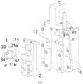
Figure 1 shows an illustrative perspective view of a connector crimping device according to an exemplary embodiment of the present invention;Figure 2 shows an illustrative view of a connector crimping device as viewed from the front side according to an exemplary embodiment of the present invention;Figure 3 shows an illustrative exploded view of a connector crimping device according to an exemplary embodiment of the present invention when viewed from the rear side;Figure 4 shows an illustrative assembly view of the first movable block, second movable block, and installation shaft of a connector crimping device according to an exemplary embodiment of the present invention;Figure 5 shows an illustrative exploded view of the firstmovable block 1, secondmovable block 2, andinstallation shaft 3 of the connector crimping device according to an exemplary embodiment of the present invention;Figure 6 shows an illustrative view of theinstallation shaft 3 of a connector crimping device according to an exemplary embodiment of the present invention. - As shown in
Figures 1 to 6 , in an exemplary embodiment of the present invention, a connector crimping device is disclosed. The connector crimping device includes: a firstmovable block 1, a secondmovable block 2, and aninstallation shaft 3. The firstmovable block 1 can be moved along a first direction Z and is formed with asliding slot 12 that extends along the first direction Z. The secondmovable block 2 is installed in the slidingslot 12 of the firstmovable block 1 and can be moved along the slidingslot 12. Theinstallation shaft 3 is rotatably installed onto the firstmovable block 1 and passes through the secondmovable block 2. Theinstallation shaft 3 includes: afirst shaft portion 31 and asecond shaft portion 32. Thefirst shaft portion 31 is rotatably mated with the firstmovable block 1, and has a first central axis C1 that extends along a second direction X perpendicular to the first direction Z. Thesecond shaft portion 32 is rotatably mated with the secondmovable block 2, and has a second central axis C2 that extends along the second direction X. - As shown in
Figures 1 to 6 , in the illustrated embodiment, the second central axis C2 is offset by a predetermined distance d from the first central axis C1, so that the movement distance of the secondmovable block 2 relative to the firstmovable block 1 in the first direction Z can be adjusted by rotating theinstallation shaft 3. In this way, the crimping height of the connector crimping device in the first direction Z can be adjusted, so that the connector crimping device can be suitable for connector products with different crimping heights, expanding the application range of the connector crimping device. - As shown in
Figures 1 to 6 , in the illustrated embodiments, the first direction Z is the vertical direction, and the second direction X is the horizontal direction perpendicular to the vertical direction. However, the present invention is not limited to the illustrated embodiments, and the first direction Z can also be in the horizontal direction. - As shown in
Figures 1 to 6 , in the illustrated embodiments, apressing head 21 is provided on the secondmovable block 2, which is used to press against the terminal module of the connector to connect the terminal of the connector to the cable. -
Figure 7 shows an illustrative perspective view of a connector crimping device according to an exemplary embodiment of the present invention when viewed from the rear, wherein the firstmovable block 1 is not shown. - As shown in
Figures 1 to 7 , in the illustrated embodiment, a second mountinghole 23 is formed in the secondmovable block 2, and thesecond shaft portion 32 is rotatably fitted in the second mountinghole 23. -
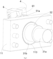
Figure 8 shows an illustrative assembly view of theinstallation shaft 3, mountingplate 11,dial 5,rotating component 4, and lockingmember 6 of the connector crimping device according to an exemplary embodiment of the present invention when viewed from the front side;Figure 9 shows an illustrative assembly view of theinstallation shaft 3,installation plate 11,dial 5,rotating component 4, and lockingmember 6 of the connector crimping device according to an exemplary embodiment of the present invention when viewed from the rear;Figure 10 shows an illustrative exploded view of theinstallation shaft 3,installation plate 11,dial 5,rotating component 4, and lockingmember 6 of the connector crimping device according to an exemplary embodiment of the present invention when viewed from the front side;Figure 11 shows an illustrative exploded view of theinstallation shaft 3,installation plate 11,dial 5,rotating component 4, and lockingmember 6 of the connector crimping device according to an exemplary embodiment of the present invention when viewed from the rear. - As shown in
Figures 1 to 11 , in the illustrated embodiments, theinstallation shaft 3 has front and rear ends opposite to each other in its axial direction. Thefirst shaft portion 31 includes: a firstrear shaft portion 31a and a firstfront shaft portion 31b. The firstrear shaft portion 31a is located at the rear end of theinstallation shaft 3. The firstfront shaft portion 31b is axially opposite to the firstrear shaft portion 31a. Thesecond shaft portion 32 is connected between the firstrear shaft portion 31a and the firstfront shaft portion 31b. - As shown in
Figures 1 to 11 , in the illustrated embodiment, the firstmovable block 1 comprises ablock body 10 and a mountingplate 11. Theblock body 10 is formed with a firstrear mounting hole 13. The slidingslot 12 is formed on theblock body 10. The mountingplate 11 is formed with a firstfront mounting hole 113 and is fixed to theblock body 10. The firstrear shaft portion 31a is rotatably fitted in the firstrear mounting hole 13, while the firstfront shaft portion 3 1b is rotatably fitted in the firstfront mounting hole 113. - As shown in
Figures 1 to 11 , in the illustrated embodiments, the connector crimping device further comprises arotating component 4, which is fixed to the front end of theinstallation shaft 3 for driving theinstallation shaft 3 to rotate around the first central axis C1. The central axis of the front end ofinstallation shaft 3 coincides with the first central axis C1. - As shown in
Figures 1 to 11 , in the illustrated embodiments, the connector crimping device further comprises adial 5 and apointer 9. Thedial 5 is fixed to the outer side of the mountingplate 11 and is formed with ascale mark 50 on its surface. Thepointer 9 is fixed to therotating component 4 or theinstallation shaft 3 to indicate the movement distance of the secondmovable block 2 relative to the firstmovable block 1. The front end of theinstallation shaft 3 passes through thedial 5 and is rotatably mated with thedial 5. - As shown in
Figures 1 to 11 , in the illustrated embodiments, a third mountinghole 53 is formed in thedial 5, and the front end of theinstallation shaft 3 has athird shaft portion 33 that is rotatably fitted in the third mountinghole 53. The firstfront shaft portion 31b is axially connected between thethird shaft portion 33 and thesecond shaft portion 32. - As shown in
Figures 1 to 11 , in the illustrated embodiments, the front end of theinstallation shaft 3 also has afourth shaft portion 34 that extends from thethird installation hole 53 of thedial 5, and aninstallation hole 43 that is mated with thefourth shaft portion 34 is formed in therotating component 4. Afirst cutting plane 34a and asecond cutting plane 43a are formed on the outer surface of thefourth shaft portion 34 and the inner surface of theinstallation hole 43, respectively, which are mutually matched, so that therotating component 4 cannot be rotated relative to theinstallation shaft 3. - As shown in
Figures 1 to 11 , in the illustrated embodiments, a threadedhole 34b is formed in the end face of thefourth shaft portion 34, and the connector crimping device further includes a threaded connectingmember 4b. The threaded connectingmember 4b passes through therotating component 4 and is threaded into the threadedhole 34b to fix therotating component 4 axially to theinstallation shaft 3. - As shown in
Figures 1 to 11 , in the illustrated embodiments, the connector crimping device further includes a lockingmember 6, which is used to lock therotating component 4 to the mountingplate 11 or thedial 5. When theinstallation shaft 3 androtating component 4 are rotated to a predetermined angle position relative to thedial 5, the lockingmember 6 locks theinstallation shaft 3 and therotating component 4 at the predetermined angle position, so that the secondmovable block 2 is held at a predetermined position relative to the firstmovable block 1. - As shown in
Figures 1 to 11 , in the illustrated embodiments, agear portion 51 is formed on thedial 5, andmultiple tooth slots 51a on thegear portion 51 respectively correspond to multiple scale marks 50 on thedial 5. A lockingtooth 61 is formed on the lockingmember 6, the lockingmember 6 is rotatably connected to therotating component 4 and can be rotated between a locking position and an unlocking position. - As shown in
Figures 1 to 11 , in the illustrated embodiments, when the lockingmember 6 is rotated to the locking position, the lockingtooth 61 is meshed with the correspondingtooth slot 51a on thegear portion 51 to lock theinstallation shaft 3 and therotating component 4 at the predetermined angle position. When the lockingmember 6 is rotated to the unlocked position, the lockingtooth 61 is detached from thetooth slot 51a on thegear section 51 to allow theinstallation shaft 3 androtating component 4 to rotate relative to thedial 5. - As shown in
Figures 1 to 11 , in the illustrated embodiments, the difference between adjacent scale marks 50 ondial 5 can be equal to 1mm, 0.5mm, 0.1mm, or 0.05mm. However, the present invention is not limited to the illustrated embodiments, for example, the difference between adjacent scale marks 50 ondial 5 can also be set to other values. - As shown in
Figures 1 to 11 , in the illustrated embodiments, the connector crimping device further comprises asensor 7, which is fixedly installed on the firstmovable block 1 for detecting the movement distance of the secondmovable block 2 relative to the firstmovable block 1 in the first direction Z. In this way, it is possible to confirm whether the movement distance indicated bypointer 9 is correct based on the movement distance detected by thesensor 7, which can improve the reliability of distance adjustment. - As shown in
Figures 1 to 11 , in the illustrated embodiment, areference block 8 is installed on the secondmovable block 2, which has areference plane 8a perpendicular to the first direction Z. Thesensor 7 is fixedly installed on theblock body 10 of the firstmovable block 1 and faces thereference plane 8a of thereference block 8 to detect the distance betweensensor 7 and thereference plane 8a. The movement distance of the secondmovable block 2 relative to the firstmovable block 1 in the first direction Z is equal to the movement distance of thereference plane 8a relative tosensor 7. - As shown in
Figures 1 to 11 , in the illustrated embodiments, thesensor 7 can be a laser distance sensor, an ultrasonic distance sensor, or an infrared distance sensor. - As shown in
Figures 1 to 11 , in the illustrated embodiments, the connector crimping device further includes a driving device (not shown), which is connected to the firstmovable block 1 for driving the firstmovable block 1 and the secondmovable block 2 to move together in the first direction Z. The driving device can be a cylinder, hydraulic cylinder, or electric cylinder. - Below is a brief explanation of the working process of the connector crimping device of the present invention.
- Firstly, fix the connector that need to be crimped in the predetermined position;
- Then, adjust the movement distance of the second
movable block 2 relative to the firstmovable block 1 according to the crimping height of the connector to be crimped; - Finally, use a driving device (such as a cylinder) to drive the first
movable block 1 and the secondmovable block 2 to move synchronously towards the terminal module of the connector for a predetermined distance. During this process, the secondmovable block 2 pushes the terminal module of the connector to crimp the connector terminal onto the cable. - As shown in
Figures 1 to 11 , in the illustrated embodiments, the firstmovable block 1 is the main movable block connected to the driving device, the secondmovable block 2 is installed on the firstmovable block 1 to move synchronously with the firstmovable block 1, and the secondmovable block 2 can be moved within a predetermined range relative to the firstmovable block 2 to adjust the crimping height of the connector crimping device, so that the connector crimping device can be suitable for connectors with different crimping heights. - It should be appreciated for those skilled in this art that the above embodiments are intended to be illustrated, and not restrictive. For example, many modifications may be made to the above embodiments by those skilled in this art, and various features described in different embodiments may be freely combined with each other without conflicting in configuration or principle.
- Although several exemplary embodiments have been shown and described, it would be appreciated by those skilled in the art that various changes or modifications may be made in these embodiments without departing from the principles and spirit of the disclosure, the scope of which is defined in the claims and their equivalents.
- As used herein, an element recited in the singular and proceeded with the word "a" or "an" should be understood as not excluding plural of said elements or steps, unless such exclusion is explicitly stated. Furthermore, references to "one embodiment" of the present invention are not intended to be interpreted as excluding the existence of additional embodiments that also incorporate the recited features. Moreover, unless explicitly stated to the contrary, embodiments "comprising" or "having" an element or a plurality of elements having a particular property may include additional such elements not having that property.
Claims (15)
- A connector crimping device, comprising:a first movable block (1) which can be moved along a first direction (Z) and is formed with a sliding slot (12) extending along the first direction (Z);a second movable block (2) which is installed in the sliding slot (12) of the first movable block (1) and can be moved along the sliding slot (12); andan installation shaft (3) which is rotatably installed to the first movable block (1) and passes through the second movable block (2),wherein the installation shaft (3) comprises:a first shaft portion (31) which is rotationally mated with the first movable block (1) and has a first central axis (C1) extending along a second direction (X) perpendicular to the first direction (Z); anda second shaft portion (32) which is rotationally mated with the second movable block (2) and has a second central axis (C2) extending along the second direction (X),wherein the second central axis (C2) is offset by a predetermined distance (d) from the first central axis (C1), so that the movement distance of the second movable block (2) relative to the first movable block (1) in the first direction (Z) can be adjusted by rotating the installation shaft (3).
- The connector crimping device according to claim 1,wherein a pressing head (21) is provided on the second movable block (2), the pressing head (21) is used to press against a terminal module of the connector to crimp a terminal of the terminal module to a cable,wherein a second mounting hole (23) is formed in the second movable block (2), and the second shaft portion (32) is rotatably fitted in the second mounting hole (23).
- The connector crimping device according to claim 1,wherein the installation shaft (3) has a front end and a rear end opposite to each other in its axial direction;wherein the first shaft portion (31) comprises:a first rear shaft portion (31a) located at the rear end of the installation shaft (3); anda first front shaft portion (31b) which is axially opposite to the first rear shaft portion (31a),wherein the second shaft portion (32) is connected between the first rear shaft portion (31a) and the first front shaft portion (31b).
- The connector crimping device according to claim 3,wherein the first movable block (1) comprises:a block body (10) which is formed with a first rear mounting hole (13) and the sliding slot (12); anda mounting plate (11) which is formed with a first front mounting hole (113) and fixed to the block body (10),wherein the first rear shaft portion (31a) is rotatably fitted in the first rear mounting hole (13), and the first front shaft portion (31b) is rotatably fitted in the first front mounting hole (113).
- The connector crimping device according to claim 4, further comprising:a rotating component (4) which is fixed to the front end of the installation shaft (3), for driving the installation shaft (3) to rotate around the first central axis (C1),wherein the central axis of the front end of the installation shaft (3) coincides with the first central axis (C1).
- The connector crimping device according to claim 5, further comprising:a dial (5) which is fixed to the outer side of the mounting plate (11) and formed with a scale mark (50) on its surface; anda pointer (9) fixed to the rotating component (4) or the installation shaft (3), for indicating the movement distance of the second movable block (2) relative to the first movable block (1),wherein the front end of the installation shaft (3) passes through the dial (5) and is rotatably mated with the dial (5).
- The connector crimping device according to claim 6,wherein a third mounting hole (53) is formed in the dial (5), and the front end of the installation shaft (3) has a third shaft portion (33) that is rotatably fitted in the third mounting hole (53);wherein the first front shaft portion (31b) is axially connected between the third shaft portion (33) and the second shaft portion (32).
- The connector crimping device according to claim 7,wherein the front end of the installation shaft (3) also has a fourth shaft portion (34) protruding from the third installation hole (53) of the dial (5), and an installation hole (43) mated with the fourth shaft portion (34) is formed in the rotating component (4);wherein a first cutting plane (34a) and a second cutting plane (43a) that are mated with each other are formed on the outer peripheral surface of the fourth shaft portion (34) and the inner peripheral surface of the installation hole (43), respectively, so that the rotating component (4) cannot be rotated relative to the installation shaft (3).
- The connector crimping device according to claim 8,
wherein a threaded hole (34b) is formed in the end face of the fourth shaft portion (34), and the connector crimping device further comprises a threaded connecting member (4b), which passes through the rotating component (4) and is threaded into the threaded hole (34b) to fix the rotating component (4) axially to the installation shaft (3). - The connector crimping device according to any one of claims 6-9, further comprising:a locking member (6) for locking the rotating component (4) to the mounting plate (11) or the dial (5),wherein when the installation shaft (3) and the rotating component (4) are rotated to a predetermined angle position relative to the dial (5), the locking member (6) locks the installation shaft (3) and the rotating component (4) at the predetermined angle position, so that the second movable block (2) is held at a predetermined position relative to the first movable block (1).
- The connector crimping device according to claim 10,wherein a gear portion (51) is formed on the dial (5), and multiple tooth slots (51a) on the gear portion (51) respectively correspond to multiple scale marks (50) on the dial (5);wherein a locking tooth (61) is formed on the locking member (6), and the locking member (6) is rotatably connected to the rotating component (4) and can be rotated between a locking position and an unlocking position;wherein when the locking member (6) is rotated to the locking position, the locking tooth (61) is meshed with the corresponding tooth slot (51a) on the gear portion (51) to lock the installation shaft (3) and the rotating component (4) at the predetermined angle position;wherein when the locking member (6) is rotated to the unlocked position, the locking tooth (61) is detached from the tooth slot (51a) on the gear portion (51) to allow the installation shaft (3) and the rotating component (4) to rotate relative to the dial (5).
- The connector crimping device according to claim 6, further comprising:
a sensor (7) which is fixedly installed on the first movable block (1) to detect the movement distance of the second movable block (2) relative to the first movable block (1) in the first direction (Z). - The connector crimping device according to claim 12,wherein a reference block (8) is installed on the second movable block (2), and the reference block (8) has a reference plane (8a) perpendicular to the first direction (Z);wherein the sensor (7) is fixedly installed on the block body (10) of the first movable block (1) and faces the reference plane (8a) of the reference block (8) to detect the distance between the sensor (7) and the reference plane (8a);wherein the movement distance of the second movable block (2) relative to the first movable block (1) in the first direction (Z) is equal to the movement distance of the reference plane (8a) relative to the sensor (7).
- The connector crimping device according to claim 12,
wherein the sensor (7) is a laser distance sensor, an ultrasonic distance sensor, or an infrared distance sensor. - The connector crimping device according to claim 1, further comprising:
a driving device connected to the first movable block (1) for driving the first movable block (1) and the second movable block (2) to move together in the first direction (Z).
Applications Claiming Priority (1)
| Application Number | Priority Date | Filing Date | Title |
|---|---|---|---|
| CN202311038258.6A CN119496011A (en) | 2023-08-16 | 2023-08-16 | Connector crimping equipment |
Publications (1)
| Publication Number | Publication Date |
|---|---|
| EP4510395A1 true EP4510395A1 (en) | 2025-02-19 |
Family
ID=92409290
Family Applications (1)
| Application Number | Title | Priority Date | Filing Date |
|---|---|---|---|
| EP24194257.2A Pending EP4510395A1 (en) | 2023-08-16 | 2024-08-13 | Connector crimping device |
Country Status (5)
| Country | Link |
|---|---|
| US (1) | US20250058369A1 (en) |
| EP (1) | EP4510395A1 (en) |
| JP (1) | JP2025028009A (en) |
| CN (1) | CN119496011A (en) |
| TW (1) | TW202510415A (en) |
Citations (1)
| Publication number | Priority date | Publication date | Assignee | Title |
|---|---|---|---|---|
| EP0622873A2 (en) * | 1993-04-26 | 1994-11-02 | The Whitaker Corporation | RAM drive mechanism |
-
2023
- 2023-08-16 CN CN202311038258.6A patent/CN119496011A/en active Pending
-
2024
- 2024-08-13 JP JP2024134745A patent/JP2025028009A/en active Pending
- 2024-08-13 EP EP24194257.2A patent/EP4510395A1/en active Pending
- 2024-08-14 TW TW113130459A patent/TW202510415A/en unknown
- 2024-08-16 US US18/807,255 patent/US20250058369A1/en active Pending
Patent Citations (1)
| Publication number | Priority date | Publication date | Assignee | Title |
|---|---|---|---|---|
| EP0622873A2 (en) * | 1993-04-26 | 1994-11-02 | The Whitaker Corporation | RAM drive mechanism |
Also Published As
| Publication number | Publication date |
|---|---|
| JP2025028009A (en) | 2025-02-28 |
| CN119496011A (en) | 2025-02-21 |
| US20250058369A1 (en) | 2025-02-20 |
| TW202510415A (en) | 2025-03-01 |
Similar Documents
| Publication | Publication Date | Title |
|---|---|---|
| EP3289647B1 (en) | Coaxial cable connector interface for preventing mating with incorrect connector | |
| USRE31995E (en) | Enhanced detent guide track with dog-leg | |
| US4066315A (en) | Electrical connector with arcuate detent means | |
| EP2706622B1 (en) | Electical connector assembly | |
| EP0023771B1 (en) | Enhanced detent guide track with dog-leg | |
| US5067909A (en) | Locking multiple conductor electrical connector | |
| EP2510592B1 (en) | Connector assembly | |
| US4183605A (en) | Electrical connector with arcuate detent means | |
| US8202130B2 (en) | Data cable | |
| AU2022289158B2 (en) | Flat key with surface code and cylinder lock | |
| US4074927A (en) | Electrical connector with insert member retaining means | |
| JP7255456B2 (en) | connector device | |
| US11670897B2 (en) | Plug connectors for a plug connector system, plug connector system and method for producing a plug connector system | |
| US20050032421A1 (en) | Coaxial connector | |
| US20250058369A1 (en) | Connector crimping device | |
| EP4113056B1 (en) | Wheel positioning system and wheel positioning method | |
| US11769973B2 (en) | Plug connector and plug connector assembly | |
| EP2312699B1 (en) | Connector assembly and method of manufacturing the same | |
| CN220544444U (en) | Connector crimping apparatus | |
| EP1084433B1 (en) | Self aligning optical fiber terminator | |
| EP4340136A1 (en) | Electrical connector with comb-type terminal lock | |
| EP3866279A1 (en) | Coaxial rf connector keying system and rf connector | |
| JP2024047335A (en) | Mating Connector | |
| US9923303B2 (en) | Electrical connector with terminal centering system | |
| GB2167247A (en) | Improvements in connectors |
Legal Events
| Date | Code | Title | Description |
|---|---|---|---|
| PUAI | Public reference made under article 153(3) epc to a published international application that has entered the european phase |
Free format text: ORIGINAL CODE: 0009012 |
|
| STAA | Information on the status of an ep patent application or granted ep patent |
Free format text: STATUS: THE APPLICATION HAS BEEN PUBLISHED |
|
| AK | Designated contracting states |
Kind code of ref document: A1 Designated state(s): AL AT BE BG CH CY CZ DE DK EE ES FI FR GB GR HR HU IE IS IT LI LT LU LV MC ME MK MT NL NO PL PT RO RS SE SI SK SM TR |
|
| STAA | Information on the status of an ep patent application or granted ep patent |
Free format text: STATUS: REQUEST FOR EXAMINATION WAS MADE |
|
| 17P | Request for examination filed |
Effective date: 20250729 |