EP4510388A1 - Electrical connection system for electrical vehicles - Google Patents
Electrical connection system for electrical vehicles Download PDFInfo
- Publication number
- EP4510388A1 EP4510388A1 EP23191280.9A EP23191280A EP4510388A1 EP 4510388 A1 EP4510388 A1 EP 4510388A1 EP 23191280 A EP23191280 A EP 23191280A EP 4510388 A1 EP4510388 A1 EP 4510388A1
- Authority
- EP
- European Patent Office
- Prior art keywords
- electrical connection
- elongate portion
- connection system
- supporting member
- female terminal
- Prior art date
- Legal status (The legal status is an assumption and is not a legal conclusion. Google has not performed a legal analysis and makes no representation as to the accuracy of the status listed.)
- Pending
Links
Images




Classifications
-
- H—ELECTRICITY
- H01—ELECTRIC ELEMENTS
- H01R—ELECTRICALLY-CONDUCTIVE CONNECTIONS; STRUCTURAL ASSOCIATIONS OF A PLURALITY OF MUTUALLY-INSULATED ELECTRICAL CONNECTING ELEMENTS; COUPLING DEVICES; CURRENT COLLECTORS
- H01R13/00—Details of coupling devices of the kinds covered by groups H01R12/70 or H01R24/00 - H01R33/00
- H01R13/56—Means for preventing chafing or fracture of flexible leads at outlet from coupling part
- H01R13/562—Bending-relieving
-
- H—ELECTRICITY
- H01—ELECTRIC ELEMENTS
- H01R—ELECTRICALLY-CONDUCTIVE CONNECTIONS; STRUCTURAL ASSOCIATIONS OF A PLURALITY OF MUTUALLY-INSULATED ELECTRICAL CONNECTING ELEMENTS; COUPLING DEVICES; CURRENT COLLECTORS
- H01R11/00—Individual connecting elements providing two or more spaced connecting locations for conductive members which are, or may be, thereby interconnected, e.g. end pieces for wires or cables supported by the wire or cable and having means for facilitating electrical connection to some other wire, terminal, or conductive member, blocks of binding posts
- H01R11/03—Individual connecting elements providing two or more spaced connecting locations for conductive members which are, or may be, thereby interconnected, e.g. end pieces for wires or cables supported by the wire or cable and having means for facilitating electrical connection to some other wire, terminal, or conductive member, blocks of binding posts characterised by the relationship between the connecting locations
- H01R11/05—Individual connecting elements providing two or more spaced connecting locations for conductive members which are, or may be, thereby interconnected, e.g. end pieces for wires or cables supported by the wire or cable and having means for facilitating electrical connection to some other wire, terminal, or conductive member, blocks of binding posts characterised by the relationship between the connecting locations the connecting locations having different types of direct connections
-
- H—ELECTRICITY
- H01—ELECTRIC ELEMENTS
- H01R—ELECTRICALLY-CONDUCTIVE CONNECTIONS; STRUCTURAL ASSOCIATIONS OF A PLURALITY OF MUTUALLY-INSULATED ELECTRICAL CONNECTING ELEMENTS; COUPLING DEVICES; CURRENT COLLECTORS
- H01R13/00—Details of coupling devices of the kinds covered by groups H01R12/70 or H01R24/00 - H01R33/00
- H01R13/40—Securing contact members in or to a base or case; Insulating of contact members
-
- H—ELECTRICITY
- H01—ELECTRIC ELEMENTS
- H01R—ELECTRICALLY-CONDUCTIVE CONNECTIONS; STRUCTURAL ASSOCIATIONS OF A PLURALITY OF MUTUALLY-INSULATED ELECTRICAL CONNECTING ELEMENTS; COUPLING DEVICES; CURRENT COLLECTORS
- H01R13/00—Details of coupling devices of the kinds covered by groups H01R12/70 or H01R24/00 - H01R33/00
- H01R13/02—Contact members
-
- H—ELECTRICITY
- H01—ELECTRIC ELEMENTS
- H01R—ELECTRICALLY-CONDUCTIVE CONNECTIONS; STRUCTURAL ASSOCIATIONS OF A PLURALITY OF MUTUALLY-INSULATED ELECTRICAL CONNECTING ELEMENTS; COUPLING DEVICES; CURRENT COLLECTORS
- H01R13/00—Details of coupling devices of the kinds covered by groups H01R12/70 or H01R24/00 - H01R33/00
- H01R13/02—Contact members
- H01R13/10—Sockets for co-operation with pins or blades
- H01R13/11—Resilient sockets
- H01R13/111—Resilient sockets co-operating with pins having a circular transverse section
-
- H—ELECTRICITY
- H01—ELECTRIC ELEMENTS
- H01R—ELECTRICALLY-CONDUCTIVE CONNECTIONS; STRUCTURAL ASSOCIATIONS OF A PLURALITY OF MUTUALLY-INSULATED ELECTRICAL CONNECTING ELEMENTS; COUPLING DEVICES; CURRENT COLLECTORS
- H01R13/00—Details of coupling devices of the kinds covered by groups H01R12/70 or H01R24/00 - H01R33/00
- H01R13/02—Contact members
- H01R13/10—Sockets for co-operation with pins or blades
- H01R13/11—Resilient sockets
- H01R13/112—Resilient sockets forked sockets having two legs
-
- H—ELECTRICITY
- H01—ELECTRIC ELEMENTS
- H01R—ELECTRICALLY-CONDUCTIVE CONNECTIONS; STRUCTURAL ASSOCIATIONS OF A PLURALITY OF MUTUALLY-INSULATED ELECTRICAL CONNECTING ELEMENTS; COUPLING DEVICES; CURRENT COLLECTORS
- H01R13/00—Details of coupling devices of the kinds covered by groups H01R12/70 or H01R24/00 - H01R33/00
- H01R13/40—Securing contact members in or to a base or case; Insulating of contact members
- H01R13/405—Securing in non-demountable manner, e.g. moulding, riveting
- H01R13/41—Securing in non-demountable manner, e.g. moulding, riveting by frictional grip in grommet, panel or base
-
- H—ELECTRICITY
- H01—ELECTRIC ELEMENTS
- H01R—ELECTRICALLY-CONDUCTIVE CONNECTIONS; STRUCTURAL ASSOCIATIONS OF A PLURALITY OF MUTUALLY-INSULATED ELECTRICAL CONNECTING ELEMENTS; COUPLING DEVICES; CURRENT COLLECTORS
- H01R13/00—Details of coupling devices of the kinds covered by groups H01R12/70 or H01R24/00 - H01R33/00
- H01R13/46—Bases; Cases
- H01R13/502—Bases; Cases composed of different pieces
-
- H—ELECTRICITY
- H01—ELECTRIC ELEMENTS
- H01R—ELECTRICALLY-CONDUCTIVE CONNECTIONS; STRUCTURAL ASSOCIATIONS OF A PLURALITY OF MUTUALLY-INSULATED ELECTRICAL CONNECTING ELEMENTS; COUPLING DEVICES; CURRENT COLLECTORS
- H01R13/00—Details of coupling devices of the kinds covered by groups H01R12/70 or H01R24/00 - H01R33/00
- H01R13/62—Means for facilitating engagement or disengagement of coupling parts or for holding them in engagement
- H01R13/627—Snap or like fastening
- H01R13/6271—Latching means integral with the housing
-
- H—ELECTRICITY
- H01—ELECTRIC ELEMENTS
- H01R—ELECTRICALLY-CONDUCTIVE CONNECTIONS; STRUCTURAL ASSOCIATIONS OF A PLURALITY OF MUTUALLY-INSULATED ELECTRICAL CONNECTING ELEMENTS; COUPLING DEVICES; CURRENT COLLECTORS
- H01R24/00—Two-part coupling devices, or either of their cooperating parts, characterised by their overall structure
- H01R24/28—Coupling parts carrying pins, blades or analogous contacts and secured only to wire or cable
-
- H—ELECTRICITY
- H01—ELECTRIC ELEMENTS
- H01R—ELECTRICALLY-CONDUCTIVE CONNECTIONS; STRUCTURAL ASSOCIATIONS OF A PLURALITY OF MUTUALLY-INSULATED ELECTRICAL CONNECTING ELEMENTS; COUPLING DEVICES; CURRENT COLLECTORS
- H01R24/00—Two-part coupling devices, or either of their cooperating parts, characterised by their overall structure
- H01R24/76—Two-part coupling devices, or either of their cooperating parts, characterised by their overall structure with sockets, clips or analogous contacts and secured to apparatus or structure, e.g. to a wall
-
- H—ELECTRICITY
- H01—ELECTRIC ELEMENTS
- H01R—ELECTRICALLY-CONDUCTIVE CONNECTIONS; STRUCTURAL ASSOCIATIONS OF A PLURALITY OF MUTUALLY-INSULATED ELECTRICAL CONNECTING ELEMENTS; COUPLING DEVICES; CURRENT COLLECTORS
- H01R43/00—Apparatus or processes specially adapted for manufacturing, assembling, maintaining, or repairing of line connectors or current collectors or for joining electric conductors
- H01R43/16—Apparatus or processes specially adapted for manufacturing, assembling, maintaining, or repairing of line connectors or current collectors or for joining electric conductors for manufacturing contact members, e.g. by punching and by bending
-
- H—ELECTRICITY
- H01—ELECTRIC ELEMENTS
- H01R—ELECTRICALLY-CONDUCTIVE CONNECTIONS; STRUCTURAL ASSOCIATIONS OF A PLURALITY OF MUTUALLY-INSULATED ELECTRICAL CONNECTING ELEMENTS; COUPLING DEVICES; CURRENT COLLECTORS
- H01R43/00—Apparatus or processes specially adapted for manufacturing, assembling, maintaining, or repairing of line connectors or current collectors or for joining electric conductors
- H01R43/18—Apparatus or processes specially adapted for manufacturing, assembling, maintaining, or repairing of line connectors or current collectors or for joining electric conductors for manufacturing bases or cases for contact members
-
- H—ELECTRICITY
- H01—ELECTRIC ELEMENTS
- H01R—ELECTRICALLY-CONDUCTIVE CONNECTIONS; STRUCTURAL ASSOCIATIONS OF A PLURALITY OF MUTUALLY-INSULATED ELECTRICAL CONNECTING ELEMENTS; COUPLING DEVICES; CURRENT COLLECTORS
- H01R43/00—Apparatus or processes specially adapted for manufacturing, assembling, maintaining, or repairing of line connectors or current collectors or for joining electric conductors
- H01R43/20—Apparatus or processes specially adapted for manufacturing, assembling, maintaining, or repairing of line connectors or current collectors or for joining electric conductors for assembling or disassembling contact members with insulating base, case or sleeve
- H01R43/24—Assembling by moulding on contact members
-
- H—ELECTRICITY
- H01—ELECTRIC ELEMENTS
- H01R—ELECTRICALLY-CONDUCTIVE CONNECTIONS; STRUCTURAL ASSOCIATIONS OF A PLURALITY OF MUTUALLY-INSULATED ELECTRICAL CONNECTING ELEMENTS; COUPLING DEVICES; CURRENT COLLECTORS
- H01R13/00—Details of coupling devices of the kinds covered by groups H01R12/70 or H01R24/00 - H01R33/00
- H01R13/46—Bases; Cases
- H01R13/502—Bases; Cases composed of different pieces
- H01R13/504—Bases; Cases composed of different pieces different pieces being moulded, cemented, welded, e.g. ultrasonic welding, or swaged together
-
- H—ELECTRICITY
- H01—ELECTRIC ELEMENTS
- H01R—ELECTRICALLY-CONDUCTIVE CONNECTIONS; STRUCTURAL ASSOCIATIONS OF A PLURALITY OF MUTUALLY-INSULATED ELECTRICAL CONNECTING ELEMENTS; COUPLING DEVICES; CURRENT COLLECTORS
- H01R13/00—Details of coupling devices of the kinds covered by groups H01R12/70 or H01R24/00 - H01R33/00
- H01R13/46—Bases; Cases
- H01R13/52—Dustproof, splashproof, drip-proof, waterproof, or flameproof cases
- H01R13/5219—Sealing means between coupling parts, e.g. interfacial seal
-
- H—ELECTRICITY
- H01—ELECTRIC ELEMENTS
- H01R—ELECTRICALLY-CONDUCTIVE CONNECTIONS; STRUCTURAL ASSOCIATIONS OF A PLURALITY OF MUTUALLY-INSULATED ELECTRICAL CONNECTING ELEMENTS; COUPLING DEVICES; CURRENT COLLECTORS
- H01R2103/00—Two poles
-
- H—ELECTRICITY
- H01—ELECTRIC ELEMENTS
- H01R—ELECTRICALLY-CONDUCTIVE CONNECTIONS; STRUCTURAL ASSOCIATIONS OF A PLURALITY OF MUTUALLY-INSULATED ELECTRICAL CONNECTING ELEMENTS; COUPLING DEVICES; CURRENT COLLECTORS
- H01R2201/00—Connectors or connections adapted for particular applications
- H01R2201/26—Connectors or connections adapted for particular applications for vehicles
Definitions
- the present invention relates to an electrical connection system, in particular a system for automotive applications, having at least one female terminal arranged partially in an outer housing, the female terminal being configured to engage with a corresponding male terminal.
- the present invention further relates to a method for assembling a respective electrical connection system.
- These types of electrical connection systems comprise a female connector comprising an outer housing and a female terminal, which can engage with a corresponding male terminal for providing electrical energy.
- the female terminals are usually bent, for instance to about 90° so as to allow for flexible arrangements and orientations of wires.
- the female terminal in the female connector outer housing in a substantially central position.
- mating with a male terminal is adversely affected.
- the female terminal may be off-centered, which is detrimental for mating.
- the male terminal can damage the female terminal during mating, which adversely affects the electrical connection.
- the female terminals are usually not fixed, which makes them susceptible to movements such that they could touch an inner surface of the housing. This can lead to damages of the female terminal.
- the absence of any fixation leads to substantial wiggling of the female terminal in particular in an assembled condition if no overmold is applied and/or during the overmold process.
- An aspect of the invention relates to an electrical connection system for automotive applications, the system comprising: an outer housing defining a mating direction; at least one female terminal comprising a first elongate portion oriented substantially parallel to the mating direction and being received at least partially within a hollow portion of the housing, a second elongate portion oriented in a different direction than the mating direction, and a bent portion arranged between the first and the second elongate portion; wherein the first elongate portion has a receiving portion opposite to the bent portion for mating with a corresponding male terminal; wherein the bent portion has at least one supporting member for supporting the female terminal on a surface of the outer housing such that movement of the female terminal in the housing is substantially prevented.
- the present disclosure provides an electrical connection system, which has the advantage that it can be easily assembled.
- the arrangement of the individual components of the electrical connection system, in particular of the female terminal is maintained in a predetermined manner. This facilitates mating with a corresponding male terminal. Substantially no failures and/or damages during mating thus occur.
- the electrical connection system can hence be employed in various fields of application wherever mating with a male terminal is required. The overall flexibility of the field of applications is thus increased as no particular attention is required for mating. For instance, no particular concerns by operators and/or robots are required for mating. The costs associated with manufacturing and assembling are thus reduced.
- the female terminal is securely maintained on the surface of the outer housing. This is particularly beneficial for manufacturing steps of the electrical connection system during which a cover and/or an overmold has been applied. During such manufacturing steps, the prior art solutions are usually prone to wiggling and/or movements of the female terminals, which makes an accurate positioning of the female terminal in an outer housing of prior art solutions difficult.
- the supporting member has the advantage that any accidental movement of the female terminal is prevented. The female terminal is thus protected against unintentional rearrangement, reorientation, shifting or similar.
- the supporting member of the bent portion of the female terminal significantly facilitates assembly and improves the reliability of the electrical connection system. As understood, also serviceability thereof is enhanced.
- any terminal may be understood as an electrical terminal that allows for electrical connection.
- the first elongate portion and the second elongate portion are understood as each having a shape, which has at least one dimension being larger than any of the other two dimensions. Hence, one may recognize an elongate axis, which defines the first portion and the second portion as the first elongate portion and the second elongate portion, respectively.
- the shapes of the first elongate portion and the second elongate portion may be different from one another.
- the first elongate portion and the second elongate portion may be portions of the female terminal of any length, respectively.
- an extension of the first elongate portion and the second elongate portion may intersect at an intersection point or intersection edge, the first elongate portion and the second elongate portion itself may not necessarily abut to the bent portion between these two elongate portions. Nevertheless, it is preferred when the first elongate portion and the second elongate portion each abut the bent portion on opposing sides thereof.
- the second elongate portion being oriented in a different direction than the mating direction means that their elongate axes are not parallel to one another. Preferably, they are oriented such that an angle can be defined in the bent portion as described elsewhere herein.
- the first elongate portion, the second elongate portion, and the bent portion may be arranged substantially on one plane, the plane being parallel to the mating direction.
- the mating direction may be understood by the skilled person as the direction in which a male terminal and a female terminal move so as to provide for a mating condition.
- the unmating direction may be parallel to the mating direction but oriented in the opposite direction.
- the hollow portion of the housing may be sufficiently large to accommodate the first elongate portion. It may be larger so as to accommodate one or more further elements, such as a shielding element as described elsewhere herein.
- the bent portion may be understood as encompassing a part of the female terminal in which the different orientation of the first elongate portion and the second elongate portion becomes visually apparent. This may be illustrated as follows.
- the first elongate portion and the second elongate portion may be implemented by strips of metal and an extension of each of the first elongate portion and the second elongate portion may define an intersection point or intersection edge.
- a part encompassing this point or edge as well as a proximity to this point or edge may be referred to as the bent portion.
- the bent portion may comprise a part of the extension of the first elongate portion and/or a part of the extension of the second elongate portion.
- the bent portion of the female terminal may not be limited to the mathematical point or edge at which an extension of each of the first elongate portion and the second elongate portion intersect.
- the receiving portion may be arranged substantially at one end of the female terminal.
- the supporting member may be understood as a structural element with the intended purpose to substantially prevent movement or the like of the female terminal in the housing. In particular, movement of the first elongate portion may substantially be prevented.
- the supporting member requires more than a mere arbitrary part, surface, or the like, which affects for instance the center of mass of the female terminal merely by its presence.
- the surface of the outer housing may be facing the second elongate portion.
- the surface may have a normal, the normal being parallel to the mating direction.
- the electrical connection system may comprise a plurality of female terminals.
- two female terminals are comprised by the electrical connection system. These two female terminals may substantially be the same.
- the at least one supporting member is arranged such that a free edge of the supporting member contacts the surface of the outer housing at least partially.
- the free edge contacting the surface at least partially has the advantage that the female terminal is supported to a greater extent.
- the free edge of the supporting member may contact the surface additionally or alternatively with the whole edge's surface facing the surface of the outer housing.
- the at least one supporting member is bent in the mating direction and extends from the second elongate portion such that the free edge substantially abuts the surface along its length in the direction of the second elongate portion.
- the direction of the second elongate portion may be understood by the skilled person as the elongate direction of the second portion.
- the at least one supporting member has the shape of a wing.
- the wing has the advantage that it is a highly accepted structural element that can be easily implemented and handled in the manufacturing process.
- the wing enhances the supporting effect of the supporting member.
- the at least one supporting member is integrally formed with the female terminal as a single piece, wherein the female terminal and the at least one supporting member are preferably made from stamped and bent sheet metal.
- the manufacturing process can thus be improved.
- An integral formation reduces the number of separate pieces that are needed.
- To be made from stamped and bent sheet metal means that the female terminal may have undergone a stamping and bending process.
- the skilled person readily recognizes the differences from such manufacturing processes as compared to the provision of separated pieces, as separate pieces demand attachment means.
- the preferred embodiment described herein has the advantage that the supporting member is a rigid and firm structure on its own without the need of any attachment means.
- the surface of the housing is provided with at least one corresponding recess so as to accommodate the least one supporting member at least partially.
- the recces may have a similar shape as a part of the supporting member.
- the recess may have a similar shape as a free edge of the supporting member described elsewhere herein.
- the at least one supporting member comprises a slit on an edge facing the second elongate portion, the slit extending along the elongate direction of the second elongate portion, wherein the slit preferably starts in proximity to an intersection of the first elongate portion and the second elongate portion and extends in the direction along the second elongate portion away from the intersection, wherein the slit preferably extends to at least 5%, preferably at least 10%, preferably at least 20%, preferably at least 30%, and/or of at most 90%, preferably at most 80%, preferably at most 70%, preferably at most 60%, preferably at most 50%, preferably at most 40% of the length of the supporting member in a direction along the second elongate portion.
- the slit facilitates that the supporting member can be bent more easily. This makes it easier to bend the supporting member such that it abuts the surface of the outer housing substantially with its whole free edge. In this manner, the abutment of the supporting member and the surface can be adjusted more easily.
- the slit should not extend over such a length that stability of the supporting member may be impaired.
- the slit should extend to a sufficient length to facilitate an easier bending during manufacturing and/or assembling. According to the values specified in here, an optimum balance was found.
- the first elongate portion and the second elongate portion intersect in the bent portion with a bending radius of between 0.05 mm to 0.8 mm, preferably between 0.1 mm to 0.6 mm, preferably between 0.2 mm to 0.4 mm.
- a smaller bending radius facilitates that the supporting member may have more space on the bent portion.
- the bending radius should not be too small as this increases the mechanical stresses in the female terminal, which could be detrimental for electrical transmission.
- the values specified in here provided an optimum compromise between these conflicting requirements.
- the at least one supporting member has a width in a direction perpendicular to the second elongate portion towards the surface of at least 0.2 mm, preferably at least 0.4 mm, preferably at least 0.6 mm, preferably at least 0.8 mm, preferably at least 1 mm, and/or of at most 4 mm, preferably at most 2 mm, preferably at most 1.6 mm, preferably at most 1.4 mm, preferably at most 1.2 mm, preferably at most 1 mm.
- the width should not be too large, as this adversely affects waste of material.
- a larger width may entail a possibility of instability of the female terminal.
- the width should not be too small, as this compromises the provision of maintaining a certain distance, for instance a distance of the receiving portion of the first elongate portion to an opening of the housing as described elsewhere herein. According to the values specified in here, an optimum balance was found.
- the width of the at least one supporting member may additionally or alternatively be measured in a direction along the mating direction. It is preferred that the mating direction is substantially perpendicular to the second elongate portion of the female terminal.
- the at least one supporting member has a length in a direction along the second elongate portion of at least 0.4 mm, preferably at least 0.6 mm, preferably at least 0.8 mm, preferably at least 1 mm, preferably at least 1.5 mm, and/or of at most 4 mm, preferably at most 3 mm, preferably at most 2 mm, preferably at most 1.8 mm, preferably at most 1.5 mm.
- the length should not be too large, as this adversely affects waste of material.
- the length should not be too small, as this compromises the beneficial supporting effect of the female terminal on the surface of the outer housing.
- the first elongate portion and the second elongate portion intersect at the bent portion by an angle of at least 60°, preferably at least 70°, preferably at least 80°, preferably at least 85°, and/or by an angle of at most 120°, preferably at most 110°, preferably at most 100°, preferably at most 95°, most preferably by an angle of about 90°.
- the surface is a top surface arranged on an end of the housing opposite to the receiving portion and substantially perpendicular to the mating direction.
- the bent portion encompasses a portion of the female terminal of at least 1 time, preferably at least 2 times, preferably at least 3 times, preferably at least 4 times, preferably at least 6 times, preferably at least 8 times, preferably at least 10 times, and/or of at most 20 times, preferably at most 16 times, preferably at most 14 times, preferably at most 12 times, preferably at most 10 times of a bending radius of the intersection of an extension of the first elongate portion and an extension of the second elongate portion.
- the bent portion of the female terminal may not be limited to the mathematical point or edge at which an extension of each of the first elongate portion and the second elongate portion intersect.
- the bent portion has two supporting members arranged substantially symmetrically on opposite sides of the bent portion, wherein the surface of the housing is provided with two corresponding recesses arranged substantially symmetrically on opposite sides of the bent portion so as to accommodate the two supporting members at least partially.
- the at least one supporting member protrudes from the second elongate portion substantially perpendicularly.
- the housing comprises at least one opening to which the receiving portion of the at least one female connector is directed, wherein the receiving portion is arranged substantially centrally in the opening as seen along the mating direction.
- the electrical connection system further comprises a second female terminal arranged in a plane substantially parallel to the first female terminal, wherein the system preferably comprises at least one shielding element with a through hole for receiving the at least one female terminal, the shielding element for being received within the hollow portion of the housing, wherein the system preferably comprises a cover arranged on top of the surface of the housing for covering the housing and the at least one female terminal at least partially, wherein the system preferably comprises at least one wire connected to the second elongate portion at an end portion thereof opposite the bent portion of the female terminal, wherein the system preferably comprises an overmold arranged on top of the cover configured to accommodate the cover and the at least one wire at least partially, wherein the system preferably comprises a sealing element arranged between the overmold and the housing.
- a further aspect is related to a method for assembling an electrical connection system, the method comprising the steps of: providing an electrical connection system according to any one of the preceding claims; optionally providing a sealing element between the overmold and the housing; optionally connecting at least one wire to the second elongate portion at an end portion thereof opposite the bent portion of the female terminal; providing a cover on top of the surface of the housing for covering the housing and the at least one female terminal at least partially; providing an overmold on top of the cover configured to accommodate the cover and the at least one wire at least partially.
- the method comprises all advantages of the electrical connection system described herein. Particularly, it is noted that the method as described herein may include all aspects and/or embodiments described herein, even if not expressly described as a method but rather with reference to the electrical connection system. It is also to be understood that the features and advantages described with reference to the electrical connection system may equally be applicable to the method as described herein.
- a and/or B may represent three conditions: i.e., independent existence of A, existence of both A and B and independent existence of B.
- the character "/" in the disclosure usually represents that previous and next associated objects form an "or" relationship.
- Fig. 1 , Fig. 2a , Fig. 2b , and Fig. 2c show an electrical connection system 1 according to the prior art. Some of the features may also be useful to understand the electrical connection system 1 of to the present invention in greater detail. Further, some features may also be compatible to the electrical connection system 1 of the present invention.
- Fig. 1 is an exploded view and shows an outer housing 20, a sealing element 70, two shielding elements 30, two female terminals 10, two wires 60 each connected to each of the two female terminals 10, respectively, a cover 40 and an overmold 50.
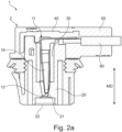
- Fig. 2a shoes a female connector 2, a bent portion 11, a receiving portion, a cavity 21 in the outer housing 20, and an opening 22.
- Fig. 1 is an exploded view and shows an outer housing 20, a sealing element 70, two shielding elements 30, two female terminals 10, two wires 60 each connected to each of the two female terminals 10, respectively, a cover 40 and an overmold 50.
- Fig. 2a shoes a female connector 2,
- connection system 1 of the prior art shoes that the female terminal 10 is not positioned correctly.
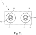
- the female terminal 10 is oblique and not parallel to the mating direction MD. Particularly the tulips are not at their correct position (as best seen in Fig. 2c ).
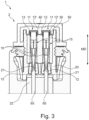
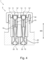
- Fig. 3 , Fig. 4, and Fig. 4 show an electrical connection system 1 according to an embodiment of the present disclosure.
- the bent portion 11 of the female terminal 10 has at least one supporting element 13 for supporting the female terminal 10 on a surface 23 of the outer housing 20 such that movement of the female terminal 10 in the outer housing 20 is substantially prevented.
- the at least one female terminal 10 (two of which are shown in Fig. 3 , Fig. 4, and Fig. 4 ) comprises a first elongate portion 15 oriented substantially parallel to the mating direction MD and being received at least partially within a hollow portion of the housing 20, a second elongate portion 16 oriented in a different direction than the mating direction MD.
- the hollow portion may comprise a part of the cavity 21.
- the bent portion 13 is arranged between the first 15 and the second 16 elongate portion.
- the supporting member 13 is arranged such that a free edge thereof contacts the surface 23 of the outer housing 20. In particular, the free edge abuts the surface 23 along its length in the direction of the second elongate portion 16.
- the supporting member 13 is bent in the mating direction MD and extends from the second elongate portion 16.
- the supporting member 13, 13' has the shape of a wing.
- the surface 23 of the outer housing 20 is provided with a corresponding recess for each of the supporting member 13, 13', so as to accommodate them at least partially.
- each of the supporting member 13, 13' comprises a slit 17 (merely one is indicated for brevity) on an edge facing the second elongate portion 16.
- the slit 17 extends along the elongate direction of the second elongate portion 16.
- the slit 17 starts in proximity to an intersection of the first elongate portion 15 (as seen in Fig. 3 and Fig. 4 ) and the second elongate portion 16 and extends in the direction along the second elongate portion 16.
- the first elongate portion 15 and the second elongate portion 16 intersect in the bent portion 11 with a bending radius 18 (as indicated in Fig. 2b of the prior art) as described elsewhere herein.
- the width w and length l of the supporting member 13, 13' are indicated in Fig. 8 .
- the first elongate portion 15 and the second elongate portion 16 may intersect at the bent portion 11 by an angle of about 90°.
- the surface 23 is a top surface arranged on an end of the outer housing 20 opposite to the receiving portion 12 and substantially perpendicular to the mating direction MD.
- the bent portion 11 encompasses a portion that is greater than the mathematical point or edge at which an extension of each of the first elongate portion 15 and the second elongate portion 16 intersect.
- the receiving portion 12 may be arranged substantially centrally in the opening 22 as seen along the mating direction MD.
- the receiving portion 12 of the female terminal 10 may be spaced apart from the opening 22 by a predefined distance.
- the supporting member 13 may be configured to maintain a predefined distance between the second elongate portion 16 and the surface 23 of the outer housing 20.
- an annular gap is formed between the first elongate portion 15 and the hollow portion of the outer housing 20.
- the annular gap may be substantially uniform along its circumference.
- Preferred wires 60 as used in the electrical connection system 1 of the present disclosure may have a size of 0.2 mm 2 to 0.8 mm, preferably 0.3 mm 2 to 0.6 mm, preferably 0.35 mm 2 to 0.5 mm.
- Fig. 6 , Fig. 7 , and Fig. 8 show different steps of a manufacturing process of a female terminal 10 according to an embodiment of the present disclosure.
- the supporting members 13, 13' (only two of which are indicated in Fig. 6 for brevity) are integrally formed with the female terminal 10 as a single piece.
- the female terminal 10 and the supporting member 13, 13' are made from stamped and bent sheet metal. A portion A between each female terminal 10 is cut off as best seen in Fig. 6 . This allows that the supporting members 13, 13' adopt the shape of wings.
- the female terminal 10 is bent to about 90° as seen in Fig. 8 compared to Fig. 7 .
Landscapes
- Engineering & Computer Science (AREA)
- Manufacturing & Machinery (AREA)
- Connector Housings Or Holding Contact Members (AREA)
Abstract
The present invention relates to an electrical connection system for automotive applications, the system comprising: an outer housing defining a mating direction; at least one female terminal comprising a first elongate portion oriented substantially parallel to the mating direction and being received at least partially within a hollow portion of the housing, a second elongate portion oriented in a different direction than the mating direction, and a bent portion arranged between the first and the second elongate portion; wherein the first elongate portion has a receiving portion opposite to the bent portion for mating with a corresponding male terminal; wherein the bent portion has at least one supporting member for supporting the female terminal on a surface of the outer housing such that movement of the female terminal in the housing is substantially prevented.
Description
- The present invention relates to an electrical connection system, in particular a system for automotive applications, having at least one female terminal arranged partially in an outer housing, the female terminal being configured to engage with a corresponding male terminal. The present invention further relates to a method for assembling a respective electrical connection system.
- In recent years the automotive sector has been facing a shift towards electric vehicles, which are becoming more and more important and popular among consumers. This shift, in turn, is accompanied by a growing demand of electrical parts and components. This also increases the demand of electrical connection systems, which are useful to connect one electrical part to another electrical part. On the one hand such electrical connections are useful to transmit electrical power to electric consumers. On the other hand such electrical connections facilitate the distribution of data in automotive vehicles.
- These types of electrical connection systems comprise a female connector comprising an outer housing and a female terminal, which can engage with a corresponding male terminal for providing electrical energy. The female terminals are usually bent, for instance to about 90° so as to allow for flexible arrangements and orientations of wires.
- The present situation of such an electrical connection system, in particular as used in the automotive sector, reveals several drawbacks.
- For instance, it is difficult to keep the female terminal in the female connector outer housing in a substantially central position. In turn, mating with a male terminal is adversely affected. In particular, the female terminal may be off-centered, which is detrimental for mating. In addition, the male terminal can damage the female terminal during mating, which adversely affects the electrical connection. Further, the female terminals are usually not fixed, which makes them susceptible to movements such that they could touch an inner surface of the housing. This can lead to damages of the female terminal. In addition, the absence of any fixation leads to substantial wiggling of the female terminal in particular in an assembled condition if no overmold is applied and/or during the overmold process.
- Overall, some electrical connection systems are thus unsuitable to be used in the automotive sector, which can lead to an increase in junk material. In turn, this significantly increases manufacturers' costs.
- Against this background, there is a need to improve the presently known electrical connection systems, as the present situation fails to address manufacturers' needs.
- It is thus an object of the present invention to overcome some or all of the deficiencies of the prior art. In particular, it is an object of the invention to provide for an electrical connection system that allows to be easily assembled with a firm, stationary and predefined arrangement. In addition, mating with a male terminal should be simplified. It is a general objective to reduce costs and to increase flexibility by the provision of an improved electrical connection system.
- The above-mentioned objects are at least partially achieved by the subject-matter of the independent claims. Preferred embodiments are subject of the dependent claims, and the skilled person finds hints for other suitable aspects of the present invention through the overall disclosure of the present application.
- An aspect of the invention relates to an electrical connection system for automotive applications, the system comprising: an outer housing defining a mating direction; at least one female terminal comprising a first elongate portion oriented substantially parallel to the mating direction and being received at least partially within a hollow portion of the housing, a second elongate portion oriented in a different direction than the mating direction, and a bent portion arranged between the first and the second elongate portion; wherein the first elongate portion has a receiving portion opposite to the bent portion for mating with a corresponding male terminal; wherein the bent portion has at least one supporting member for supporting the female terminal on a surface of the outer housing such that movement of the female terminal in the housing is substantially prevented.
- In this manner, the present disclosure provides an electrical connection system, which has the advantage that it can be easily assembled. The arrangement of the individual components of the electrical connection system, in particular of the female terminal is maintained in a predetermined manner. This facilitates mating with a corresponding male terminal. Substantially no failures and/or damages during mating thus occur. The electrical connection system can hence be employed in various fields of application wherever mating with a male terminal is required. The overall flexibility of the field of applications is thus increased as no particular attention is required for mating. For instance, no particular concerns by operators and/or robots are required for mating. The costs associated with manufacturing and assembling are thus reduced.
- Attributable to the supporting member, the female terminal is securely maintained on the surface of the outer housing. This is particularly beneficial for manufacturing steps of the electrical connection system during which a cover and/or an overmold has been applied. During such manufacturing steps, the prior art solutions are usually prone to wiggling and/or movements of the female terminals, which makes an accurate positioning of the female terminal in an outer housing of prior art solutions difficult. According to the electrical connection system proposed in here invention, the supporting member has the advantage that any accidental movement of the female terminal is prevented. The female terminal is thus protected against unintentional rearrangement, reorientation, shifting or similar.
- All in all the combination the supporting member of the bent portion of the female terminal significantly facilitates assembly and improves the reliability of the electrical connection system. As understood, also serviceability thereof is enhanced.
- As used herein, any terminal may be understood as an electrical terminal that allows for electrical connection.
- The first elongate portion and the second elongate portion are understood as each having a shape, which has at least one dimension being larger than any of the other two dimensions. Hence, one may recognize an elongate axis, which defines the first portion and the second portion as the first elongate portion and the second elongate portion, respectively. The shapes of the first elongate portion and the second elongate portion may be different from one another.
- The first elongate portion and the second elongate portion may be portions of the female terminal of any length, respectively. As understood, since an extension of the first elongate portion and the second elongate portion may intersect at an intersection point or intersection edge, the first elongate portion and the second elongate portion itself may not necessarily abut to the bent portion between these two elongate portions. Nevertheless, it is preferred when the first elongate portion and the second elongate portion each abut the bent portion on opposing sides thereof.
- The second elongate portion being oriented in a different direction than the mating direction means that their elongate axes are not parallel to one another. Preferably, they are oriented such that an angle can be defined in the bent portion as described elsewhere herein. The first elongate portion, the second elongate portion, and the bent portion may be arranged substantially on one plane, the plane being parallel to the mating direction.
- The mating direction may be understood by the skilled person as the direction in which a male terminal and a female terminal move so as to provide for a mating condition. The unmating direction may be parallel to the mating direction but oriented in the opposite direction.
- The hollow portion of the housing may be sufficiently large to accommodate the first elongate portion. It may be larger so as to accommodate one or more further elements, such as a shielding element as described elsewhere herein.
- The bent portion may be understood as encompassing a part of the female terminal in which the different orientation of the first elongate portion and the second elongate portion becomes visually apparent. This may be illustrated as follows. The first elongate portion and the second elongate portion may be implemented by strips of metal and an extension of each of the first elongate portion and the second elongate portion may define an intersection point or intersection edge. A part encompassing this point or edge as well as a proximity to this point or edge may be referred to as the bent portion. In this manner, the bent portion may comprise a part of the extension of the first elongate portion and/or a part of the extension of the second elongate portion. In other words, the bent portion of the female terminal may not be limited to the mathematical point or edge at which an extension of each of the first elongate portion and the second elongate portion intersect.
- The receiving portion may be arranged substantially at one end of the female terminal.
- The supporting member may be understood as a structural element with the intended purpose to substantially prevent movement or the like of the female terminal in the housing. In particular, movement of the first elongate portion may substantially be prevented. As understood by the skilled person, the supporting member requires more than a mere arbitrary part, surface, or the like, which affects for instance the center of mass of the female terminal merely by its presence.
- It is understood that the surface of the outer housing may be facing the second elongate portion. In one example, the surface may have a normal, the normal being parallel to the mating direction.
- The electrical connection system may comprise a plurality of female terminals. Preferably, two female terminals are comprised by the electrical connection system. These two female terminals may substantially be the same.
- It is noted that when feature, aspects, and/or embodiments are described herein by the term "substantially", manufacturing tolerances usually have to be taken into consideration. In this manner, minor deviations during any kind of manufacturing, assembling or the like may pertain. Further, manufacturing tolerances, aging effects, or other minor defects or the like may pertain. These are all encompassed by the term "substantially".
- In a preferred embodiment of the electrical connection system, the at least one supporting member is arranged such that a free edge of the supporting member contacts the surface of the outer housing at least partially.
- The free edge contacting the surface at least partially has the advantage that the female terminal is supported to a greater extent. The free edge of the supporting member may contact the surface additionally or alternatively with the whole edge's surface facing the surface of the outer housing.
- In a preferred embodiment of the electrical connection system, the at least one supporting member is bent in the mating direction and extends from the second elongate portion such that the free edge substantially abuts the surface along its length in the direction of the second elongate portion.
- This has the advantage that the supporting effect is enhanced. In turn, the mating can be improved.
- The direction of the second elongate portion may be understood by the skilled person as the elongate direction of the second portion.
- In a preferred embodiment of the electrical connection system, the at least one supporting member has the shape of a wing.
- The wing has the advantage that it is a highly accepted structural element that can be easily implemented and handled in the manufacturing process. The wing enhances the supporting effect of the supporting member.
- In a preferred embodiment of the electrical connection system, the at least one supporting member is integrally formed with the female terminal as a single piece, wherein the female terminal and the at least one supporting member are preferably made from stamped and bent sheet metal.
- The manufacturing process can thus be improved. An integral formation reduces the number of separate pieces that are needed. To be made from stamped and bent sheet metal means that the female terminal may have undergone a stamping and bending process. The skilled person readily recognizes the differences from such manufacturing processes as compared to the provision of separated pieces, as separate pieces demand attachment means. The preferred embodiment described herein has the advantage that the supporting member is a rigid and firm structure on its own without the need of any attachment means.
- In a preferred embodiment of the electrical connection system, the surface of the housing is provided with at least one corresponding recess so as to accommodate the least one supporting member at least partially.
- This has the advantage that securing and maintaining the female terminal in a correct position is enhanced. The recces may have a similar shape as a part of the supporting member. In particular, the recess may have a similar shape as a free edge of the supporting member described elsewhere herein.
- In a preferred embodiment of the electrical connection system, the at least one supporting member comprises a slit on an edge facing the second elongate portion, the slit extending along the elongate direction of the second elongate portion, wherein the slit preferably starts in proximity to an intersection of the first elongate portion and the second elongate portion and extends in the direction along the second elongate portion away from the intersection, wherein the slit preferably extends to at least 5%, preferably at least 10%, preferably at least 20%, preferably at least 30%, and/or of at most 90%, preferably at most 80%, preferably at most 70%, preferably at most 60%, preferably at most 50%, preferably at most 40% of the length of the supporting member in a direction along the second elongate portion.
- This slit the advantage that manufacturing and/or provision of the female terminal is improved. For instance, the slit facilitates that the supporting member can be bent more easily. This makes it easier to bend the supporting member such that it abuts the surface of the outer housing substantially with its whole free edge. In this manner, the abutment of the supporting member and the surface can be adjusted more easily.
- On the one hand, the slit should not extend over such a length that stability of the supporting member may be impaired. On the other hand, the slit should extend to a sufficient length to facilitate an easier bending during manufacturing and/or assembling. According to the values specified in here, an optimum balance was found.
- In a preferred embodiment of the electrical connection system, the first elongate portion and the second elongate portion intersect in the bent portion with a bending radius of between 0.05 mm to 0.8 mm, preferably between 0.1 mm to 0.6 mm, preferably between 0.2 mm to 0.4 mm.
- A smaller bending radius facilitates that the supporting member may have more space on the bent portion. However, the bending radius should not be too small as this increases the mechanical stresses in the female terminal, which could be detrimental for electrical transmission. The values specified in here provided an optimum compromise between these conflicting requirements.
- In a preferred embodiment of the electrical connection system, the at least one supporting member has a width in a direction perpendicular to the second elongate portion towards the surface of at least 0.2 mm, preferably at least 0.4 mm, preferably at least 0.6 mm, preferably at least 0.8 mm, preferably at least 1 mm, and/or of at most 4 mm, preferably at most 2 mm, preferably at most 1.6 mm, preferably at most 1.4 mm, preferably at most 1.2 mm, preferably at most 1 mm.
- This ensures that an optimum width of the supporting member is achieved. On the one hand, the width should not be too large, as this adversely affects waste of material. In addition, a larger width may entail a possibility of instability of the female terminal. On the other hand, the width should not be too small, as this compromises the provision of maintaining a certain distance, for instance a distance of the receiving portion of the first elongate portion to an opening of the housing as described elsewhere herein. According to the values specified in here, an optimum balance was found.
- The width of the at least one supporting member may additionally or alternatively be measured in a direction along the mating direction. It is preferred that the mating direction is substantially perpendicular to the second elongate portion of the female terminal.
- In a preferred embodiment of the electrical connection system, the at least one supporting member has a length in a direction along the second elongate portion of at least 0.4 mm, preferably at least 0.6 mm, preferably at least 0.8 mm, preferably at least 1 mm, preferably at least 1.5 mm, and/or of at most 4 mm, preferably at most 3 mm, preferably at most 2 mm, preferably at most 1.8 mm, preferably at most 1.5 mm.
- This ensures that an optimum length of the supporting member is achieved. On the one hand, the length should not be too large, as this adversely affects waste of material. On the other hand, the length should not be too small, as this compromises the beneficial supporting effect of the female terminal on the surface of the outer housing. Thus, the inventors found that an optimum balance according to the proposed values in here should be struck.
- In a preferred embodiment of the electrical connection system, the first elongate portion and the second elongate portion intersect at the bent portion by an angle of at least 60°, preferably at least 70°, preferably at least 80°, preferably at least 85°, and/or by an angle of at most 120°, preferably at most 110°, preferably at most 100°, preferably at most 95°, most preferably by an angle of about 90°.
- In a preferred embodiment of the electrical connection system, the surface is a top surface arranged on an end of the housing opposite to the receiving portion and substantially perpendicular to the mating direction.
- In a preferred embodiment of the electrical connection system, the bent portion encompasses a portion of the female terminal of at least 1 time, preferably at least 2 times, preferably at least 3 times, preferably at least 4 times, preferably at least 6 times, preferably at least 8 times, preferably at least 10 times, and/or of at most 20 times, preferably at most 16 times, preferably at most 14 times, preferably at most 12 times, preferably at most 10 times of a bending radius of the intersection of an extension of the first elongate portion and an extension of the second elongate portion.
- As described elsewhere herein, the bent portion of the female terminal may not be limited to the mathematical point or edge at which an extension of each of the first elongate portion and the second elongate portion intersect.
- In a preferred embodiment of the electrical connection system, the bent portion has two supporting members arranged substantially symmetrically on opposite sides of the bent portion, wherein the surface of the housing is provided with two corresponding recesses arranged substantially symmetrically on opposite sides of the bent portion so as to accommodate the two supporting members at least partially.
- Preferably, the at least one supporting member protrudes from the second elongate portion substantially perpendicularly.
- Preferably, the housing comprises at least one opening to which the receiving portion of the at least one female connector is directed, wherein the receiving portion is arranged substantially centrally in the opening as seen along the mating direction.
- Preferably, the electrical connection system further comprises a second female terminal arranged in a plane substantially parallel to the first female terminal, wherein the system preferably comprises at least one shielding element with a through hole for receiving the at least one female terminal, the shielding element for being received within the hollow portion of the housing, wherein the system preferably comprises a cover arranged on top of the surface of the housing for covering the housing and the at least one female terminal at least partially, wherein the system preferably comprises at least one wire connected to the second elongate portion at an end portion thereof opposite the bent portion of the female terminal, wherein the system preferably comprises an overmold arranged on top of the cover configured to accommodate the cover and the at least one wire at least partially, wherein the system preferably comprises a sealing element arranged between the overmold and the housing.
- A further aspect is related to a method for assembling an electrical connection system, the method comprising the steps of: providing an electrical connection system according to any one of the preceding claims; optionally providing a sealing element between the overmold and the housing; optionally connecting at least one wire to the second elongate portion at an end portion thereof opposite the bent portion of the female terminal; providing a cover on top of the surface of the housing for covering the housing and the at least one female terminal at least partially; providing an overmold on top of the cover configured to accommodate the cover and the at least one wire at least partially.
- The method comprises all advantages of the electrical connection system described herein. Particularly, it is noted that the method as described herein may include all aspects and/or embodiments described herein, even if not expressly described as a method but rather with reference to the electrical connection system. It is also to be understood that the features and advantages described with reference to the electrical connection system may equally be applicable to the method as described herein.
- In the following, preferred embodiments of the disclosure are disclosed by reference to the accompanying figures.
- Fig. 1:
- illustrates an electrical connection system according to the prior art.
- Fig. 2a:
- illustrates an electrical connection system according to the prior art in a schematic cross-sectional view from a side.
- Fig. 2b:
- illustrates the embodiment of
Fig. 2a with a male terminal in a mating condition. - Fig. 2c:
- illustrates the embodiment of
Fig. 2a from a bottom view. - Fig. 3:
- illustrates an electrical connection system according to an embodiment of the present disclosure in a schematic cross-sectional view from a side.
- Fig. 4:
- illustrates an electrical connection system according to an embodiment of the present disclosure in a cross-sectional view from a side.
- Fig. 5:
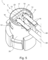
- illustrates an electrical connection system according to an embodiment of the present disclosure in a perspective view.
- Fig. 6:
- illustrates a manufacturing process of a female terminal according to an embodiment of the present disclosure in a first step.
- Fig. 7:
- illustrates a manufacturing process of a female terminal according to an embodiment of the present disclosure in a second step.
- Fig. 8:
- illustrates a manufacturing process of a female terminal according to an embodiment of the present disclosure in a third step.
- The term "and/or" is only an association relationship describing associated objects and represents that three relationships may exist. For example, A and/or B may represent three conditions: i.e., independent existence of A, existence of both A and B and independent existence of B. In addition, the character "/" in the disclosure usually represents that previous and next associated objects form an "or" relationship.
- In the subsequent passages, the invention is described with reference to the accompanying figures in more detail. It is noted that further embodiments are certainly possible, and the below explanations are provided by way of example only, without limitation. Throughout the present figures and specification, the same reference numerals refer to the same elements. The figures may not be to scale, and the relative size, proportions, and depiction of elements in the figures may be exaggerated for clarity, illustration, and convenience.
-
Fig. 1 ,Fig. 2a ,Fig. 2b , andFig. 2c show anelectrical connection system 1 according to the prior art. Some of the features may also be useful to understand theelectrical connection system 1 of to the present invention in greater detail. Further, some features may also be compatible to theelectrical connection system 1 of the present invention.Fig. 1 is an exploded view and shows anouter housing 20, a sealingelement 70, two shieldingelements 30, twofemale terminals 10, twowires 60 each connected to each of the twofemale terminals 10, respectively, acover 40 and anovermold 50.Fig. 2a shoes afemale connector 2, abent portion 11, a receiving portion, acavity 21 in theouter housing 20, and anopening 22.Fig. 2b shoes a mated condition with amale terminal 65. Theconnection system 1 of the prior art shoes that thefemale terminal 10 is not positioned correctly. Thefemale terminal 10 is oblique and not parallel to the mating direction MD. Particularly the tulips are not at their correct position (as best seen inFig. 2c ). -
Fig. 3 ,Fig. 4, and Fig. 4 show anelectrical connection system 1 according to an embodiment of the present disclosure. As can be seen, thebent portion 11 of thefemale terminal 10 has at least one supportingelement 13 for supporting thefemale terminal 10 on asurface 23 of theouter housing 20 such that movement of thefemale terminal 10 in theouter housing 20 is substantially prevented. - The at least one female terminal 10 (two of which are shown in
Fig. 3 ,Fig. 4, and Fig. 4 ) comprises a firstelongate portion 15 oriented substantially parallel to the mating direction MD and being received at least partially within a hollow portion of thehousing 20, a secondelongate portion 16 oriented in a different direction than the mating direction MD. The hollow portion may comprise a part of thecavity 21. Thebent portion 13 is arranged between the first 15 and the second 16 elongate portion. The supportingmember 13 is arranged such that a free edge thereof contacts thesurface 23 of theouter housing 20. In particular, the free edge abuts thesurface 23 along its length in the direction of the secondelongate portion 16. The supportingmember 13 is bent in the mating direction MD and extends from the secondelongate portion 16. As can be seen best inFig. 7 , the supportingmember 13, 13' has the shape of a wing. - As best seen in
Fig. 3 andFig. 4 , thesurface 23 of theouter housing 20 is provided with a corresponding recess for each of the supportingmember 13, 13', so as to accommodate them at least partially. - As best seen in
Fig. 5 , each of the supportingmember 13, 13' comprises a slit 17 (merely one is indicated for brevity) on an edge facing the secondelongate portion 16. Theslit 17 extends along the elongate direction of the secondelongate portion 16. Theslit 17 starts in proximity to an intersection of the first elongate portion 15 (as seen inFig. 3 andFig. 4 ) and the secondelongate portion 16 and extends in the direction along the secondelongate portion 16. - The first
elongate portion 15 and the secondelongate portion 16 intersect in thebent portion 11 with a bending radius 18 (as indicated inFig. 2b of the prior art) as described elsewhere herein. The width w and length l of the supportingmember 13, 13' are indicated inFig. 8 . The firstelongate portion 15 and the secondelongate portion 16 may intersect at thebent portion 11 by an angle of about 90°. - The
surface 23 is a top surface arranged on an end of theouter housing 20 opposite to the receivingportion 12 and substantially perpendicular to the mating direction MD. - As indicated in all figures, the
bent portion 11 encompasses a portion that is greater than the mathematical point or edge at which an extension of each of the firstelongate portion 15 and the secondelongate portion 16 intersect. - As best seen in
Fig. 3 andFig. 4 , the receivingportion 12 may be arranged substantially centrally in theopening 22 as seen along the mating direction MD. The receivingportion 12 of thefemale terminal 10 may be spaced apart from theopening 22 by a predefined distance. The supportingmember 13 may be configured to maintain a predefined distance between the secondelongate portion 16 and thesurface 23 of theouter housing 20. As best seen inFig. 3 andFig. 4 , an annular gap is formed between the firstelongate portion 15 and the hollow portion of theouter housing 20. The annular gap may be substantially uniform along its circumference. These advances cannot be achieved with theelectrical connection system 1 of the prior art (Fig. 1 ,Fig. 2a ,Fig. 2b , andFig. 2c ). -
Preferred wires 60 as used in theelectrical connection system 1 of the present disclosure may have a size of 0.2 mm2 to 0.8 mm, preferably 0.3 mm2 to 0.6 mm, preferably 0.35 mm2 to 0.5 mm. -
Fig. 6 ,Fig. 7 , andFig. 8 show different steps of a manufacturing process of afemale terminal 10 according to an embodiment of the present disclosure. - As can be seen, the supporting
members 13, 13' (only two of which are indicated inFig. 6 for brevity) are integrally formed with thefemale terminal 10 as a single piece. Thefemale terminal 10 and the supportingmember 13, 13' are made from stamped and bent sheet metal. A portion A between eachfemale terminal 10 is cut off as best seen inFig. 6 . This allows that the supportingmembers 13, 13' adopt the shape of wings. Thefemale terminal 10 is bent to about 90° as seen inFig. 8 compared toFig. 7 . -
- 1
- electrical connection system
- 2
- female connector
- 10
- female terminal
- 11
- bent portion
- 12
- receiving portion
- 13
- supporting member
- 13'
- supporting member
- 15
- first elongate portion
- 16
- second elongate portion
- 17
- slit
- 18
- bending radius
- 20
- outer housing (of female connector)
- 21
- cavity
- 22
- opening
- 23
- top surface of housing
- 30
- shielding
- 40
- cover
- 50
- overmold
- 60
- wire
- 65
- male terminal
- 70
- sealing element
- A
- portion which is cut off
- MD
- mating direction
- w
- width of the supporting member
- l
- length of the supporting member
Claims (15)
- An electrical connection system (1) for automotive applications, the system (1) comprising:an outer housing (20) defining a mating direction (MD);at least one female terminal (10) comprising a first elongate portion (15) oriented substantially parallel to the mating direction (MD) and being received at least partially within a hollow portion of the housing (20), a second elongate portion (16) oriented in a different direction than the mating direction, and a bent portion (11) arranged between the first (15) and the second (16) elongate portion;wherein the first elongate portion (15) has a receiving portion (12) opposite to the bent portion (11) for mating with a corresponding male terminal (65);wherein the bent portion (11) has at least one supporting member (13, 13') for supporting the female terminal (10) on a surface (23) of the outer housing (20) such that movement of the female terminal (10) in the housing (20) is substantially prevented.
- The electrical connection system (1) according to the preceding claim, wherein the at least one supporting member (13, 13') is arranged such that a free edge of the supporting member (13, 13') contacts the surface (23) at least partially.
- The electrical connection system (1) according to the preceding claim, wherein the at least one supporting member (13, 13') is bent in the mating direction (MD) and extends from the second elongate portion (16) such that the free edge substantially abuts the surface (23) along its length in the direction of the second elongate portion (16).
- The electrical connection system (1) according to any one of the preceding claims, wherein the at least one supporting member (13, 13') has the shape of a wing.
- The electrical connection system (1) according to any one of the preceding claims, wherein the at least one supporting member (13, 13') is integrally formed with the female terminal (10) as a single piece,
wherein the female terminal (10) and the at least one supporting member (13, 13') are preferably made from stamped and bent sheet metal. - The electrical connection system (1) according to any one of the preceding claims, wherein the surface (23) of the housing (20) is provided with at least one corresponding recess so as to accommodate the least one supporting member (13, 13') at least partially.
- The electrical connection system (1) according to any one of the preceding claims, wherein the at least one supporting member (13, 13') comprises a slit (17) on an edge facing the second elongate portion (16), the slit (17) extending along the elongate direction of the second elongate portion (16),wherein the slit (17) preferably starts in proximity of an intersection of the first elongate portion (15) and the second elongate portion (16) and extends in the direction along the second elongate portion (16),wherein the slit (17) preferably extends to at least 5%, preferably at least 10%, preferably at least 20%, preferably at least 30%, and/or of at most 90%, preferably at most 80%, preferably at most 70%, preferably at most 60%, preferably at most 50%, preferably at most 40% of the length (1) of the supporting member (13, 13') in a direction along the second elongate portion (16).
- The electrical connection system (1) according to any one of the preceding claims, wherein the first elongate portion (15) and the second elongate portion (16) intersect in the bent portion (11) with a bending radius (18) of between 0.05 mm to 0.8 mm, preferably between 0.1 mm to 0.6 mm, preferably between 0.2 mm to 0.4 mm.
- The electrical connection system (1) according to any one of the preceding claims, wherein the at least one supporting member (13, 13') has a width (w) in a direction perpendicular to the second elongate portion (16) towards the surface (23) of at least 0.2 mm, preferably at least 0.4 mm, preferably at least 0.6 mm, preferably at least 0.8 mm, preferably at least 1 mm, and/or
of at most 4 mm, preferably at most 2 mm, preferably at most 1.6 mm, preferably at most 1.4 mm, preferably at most 1.2 mm, preferably at most 1 mm. - The electrical connection system (1) according to any one of the preceding claims, wherein the at least one supporting member (13, 13') has a length (1) in a direction along the second elongate portion (16) of at least 0.4 mm, preferably at least 0.6 mm, preferably at least 0.8 mm, preferably at least 1 mm, preferably at least 1.5 mm, and/or
of at most 4 mm, preferably at most 3 mm, preferably at most 2 mm, preferably at most 1.8 mm, preferably at most 1.5 mm. - The electrical connection system (1) according to any one of the preceding claims, wherein the first elongate portion (15) and the second elongate portion (16) intersect in the bent portion (11) by an angle of at least 60°, preferably at least 70°, preferably at least 80°, preferably at least 85°, and/orby an angle of at most 120°, preferably at most 110°, preferably at most 100°, preferably at most 95°,most preferably by an angle of about 90°.
- The electrical connection system (1) according to any one of the preceding claims, wherein the surface (23) is a top surface arranged on an end of the housing (20) opposite to the receiving portion (12) and substantially perpendicular to the mating direction (MD).
- The electrical connection system (1) according to any one of the preceding claims, wherein the bent portion (11) encompasses a portion of the female terminal (10) of at least 1 time, preferably at least 2 times, preferably at least 3 times, preferably at least 4 times, preferably at least 6 times, preferably at least 8 times, preferably at least 10 times, and/or of at most 20 times, preferably at most 16 times, preferably at most 14 times, preferably at most 12 times, preferably at most 10 times of a bending radius (18) of the intersection of an extension of the first elongate portion (15) and an extension of the second elongate portion (16).
- The electrical connection system (1) according to any one of the preceding claims, wherein the bent portion (11) has two supporting members (13, 13') arranged substantially symmetrically on opposite sides of the bent portion (11), wherein the surface (23) of the housing (20) is provided with two corresponding recesses arranged substantially symmetrically on opposite sides of the bent portion (11) so as to accommodate the two supporting members (13, 13') at least partially.
- A method for assembling an electrical connection system (1), the method comprising the steps of:providing an electrical connection system (1) according to any one of the preceding claims;optionally providing a sealing element (70) between the overmold and the housing (20);optionally connecting at least one wire (60) to the second elongate portion (16) at an end portion thereof opposite the bent portion (11) of the female terminal (10);providing a cover (40) on top of the surface (23) of the housing (20) for covering the housing (20) and the at least one female terminal (10) at least partially;providing an overmold (50) on top of the cover (40) configured to accommodate the cover (40) and the at least one wire (60) at least partially.
Priority Applications (3)
| Application Number | Priority Date | Filing Date | Title |
|---|---|---|---|
| EP23191280.9A EP4510388A1 (en) | 2023-08-14 | 2023-08-14 | Electrical connection system for electrical vehicles |
| US18/782,427 US20250062568A1 (en) | 2023-08-14 | 2024-07-24 | Electrical connection system for electric vehicles |
| CN202411107907.8A CN119495980A (en) | 2023-08-14 | 2024-08-13 | Electrical connection systems for electric vehicles |
Applications Claiming Priority (1)
| Application Number | Priority Date | Filing Date | Title |
|---|---|---|---|
| EP23191280.9A EP4510388A1 (en) | 2023-08-14 | 2023-08-14 | Electrical connection system for electrical vehicles |
Publications (1)
| Publication Number | Publication Date |
|---|---|
| EP4510388A1 true EP4510388A1 (en) | 2025-02-19 |
Family
ID=87571879
Family Applications (1)
| Application Number | Title | Priority Date | Filing Date |
|---|---|---|---|
| EP23191280.9A Pending EP4510388A1 (en) | 2023-08-14 | 2023-08-14 | Electrical connection system for electrical vehicles |
Country Status (3)
| Country | Link |
|---|---|
| US (1) | US20250062568A1 (en) |
| EP (1) | EP4510388A1 (en) |
| CN (1) | CN119495980A (en) |
Citations (4)
| Publication number | Priority date | Publication date | Assignee | Title |
|---|---|---|---|---|
| WO2006068229A1 (en) * | 2004-12-24 | 2006-06-29 | Fci Asia Technology Pte Ltd. | Connector for electric fuse igniter |
| US7845992B2 (en) * | 2008-01-31 | 2010-12-07 | Fci Americas Technology, Inc. | Electrical connector with contact arm preloading |
| US20180151989A1 (en) * | 2016-11-30 | 2018-05-31 | Tyco Electronics France Sas | Electrical Connector For A Safety Restraint System |
| US10879644B2 (en) * | 2018-03-30 | 2020-12-29 | Yazaki Corporation | Busbar component, terminal block, and vehicular device |
-
2023
- 2023-08-14 EP EP23191280.9A patent/EP4510388A1/en active Pending
-
2024
- 2024-07-24 US US18/782,427 patent/US20250062568A1/en active Pending
- 2024-08-13 CN CN202411107907.8A patent/CN119495980A/en active Pending
Patent Citations (4)
| Publication number | Priority date | Publication date | Assignee | Title |
|---|---|---|---|---|
| WO2006068229A1 (en) * | 2004-12-24 | 2006-06-29 | Fci Asia Technology Pte Ltd. | Connector for electric fuse igniter |
| US7845992B2 (en) * | 2008-01-31 | 2010-12-07 | Fci Americas Technology, Inc. | Electrical connector with contact arm preloading |
| US20180151989A1 (en) * | 2016-11-30 | 2018-05-31 | Tyco Electronics France Sas | Electrical Connector For A Safety Restraint System |
| US10879644B2 (en) * | 2018-03-30 | 2020-12-29 | Yazaki Corporation | Busbar component, terminal block, and vehicular device |
Also Published As
| Publication number | Publication date |
|---|---|
| CN119495980A (en) | 2025-02-21 |
| US20250062568A1 (en) | 2025-02-20 |
Similar Documents
| Publication | Publication Date | Title |
|---|---|---|
| EP3159970B1 (en) | Cable assembly, connector, and method for manufacturing cable assembly | |
| US4327956A (en) | Low insertion force dual beam pin terminal and connector | |
| US6520812B1 (en) | Connector terminal with resilient contacts | |
| KR101659298B1 (en) | Coaxial connector with inner shielding arrangement and method of assembling one | |
| US8449338B2 (en) | Electrical connector | |
| US20200176930A1 (en) | Connector | |
| EP2736128B1 (en) | Ground terminal and connector provided therewith | |
| US20090036002A1 (en) | Connector terminal | |
| US20260039049A1 (en) | Connector | |
| WO2023275587A1 (en) | High power connector | |
| US7704103B1 (en) | Low profile terminals | |
| EP3474386B1 (en) | An electrical connector comprising a flat electrical contact terminal | |
| WO2010147722A1 (en) | Bifurcated electrical contact | |
| US20190173219A1 (en) | Connector | |
| US11043767B2 (en) | Method of forming an electrical terminal and an electrical terminal assembly | |
| JP3044378U (en) | Flat insulation-cut terminal for electrical connectors | |
| US6969272B2 (en) | Pressure welding connecting terminal and pressure welding connector receiving the same | |
| US20250062568A1 (en) | Electrical connection system for electric vehicles | |
| JPH02189869A (en) | Electric connector | |
| EP2584660B1 (en) | Connector and connector assembly | |
| CA1113166A (en) | Low insertion force dual beam pin terminal and connector | |
| EP1069650B1 (en) | Metal terminal | |
| JPH08250172A (en) | Receptacle type terminal | |
| EP2859622B1 (en) | Terminal connection structure | |
| US11652316B2 (en) | Retention clip for a mechanical strain relief of a cable |
Legal Events
| Date | Code | Title | Description |
|---|---|---|---|
| PUAI | Public reference made under article 153(3) epc to a published international application that has entered the european phase |
Free format text: ORIGINAL CODE: 0009012 |
|
| STAA | Information on the status of an ep patent application or granted ep patent |
Free format text: STATUS: THE APPLICATION HAS BEEN PUBLISHED |
|
| AK | Designated contracting states |
Kind code of ref document: A1 Designated state(s): AL AT BE BG CH CY CZ DE DK EE ES FI FR GB GR HR HU IE IS IT LI LT LU LV MC ME MK MT NL NO PL PT RO RS SE SI SK SM TR |
|
| STAA | Information on the status of an ep patent application or granted ep patent |
Free format text: STATUS: REQUEST FOR EXAMINATION WAS MADE |
|
| 17P | Request for examination filed |
Effective date: 20250811 |