EP4510352A1 - Housing, battery cell, battery, and electric device - Google Patents
Housing, battery cell, battery, and electric device Download PDFInfo
- Publication number
- EP4510352A1 EP4510352A1 EP23859207.5A EP23859207A EP4510352A1 EP 4510352 A1 EP4510352 A1 EP 4510352A1 EP 23859207 A EP23859207 A EP 23859207A EP 4510352 A1 EP4510352 A1 EP 4510352A1
- Authority
- EP
- European Patent Office
- Prior art keywords
- groove segment
- wall
- housing
- groove
- weak portion
- Prior art date
- Legal status (The legal status is an assumption and is not a legal conclusion. Google has not performed a legal analysis and makes no representation as to the accuracy of the status listed.)
- Pending
Links
Images




Classifications
-
- H—ELECTRICITY
- H01—ELECTRIC ELEMENTS
- H01M—PROCESSES OR MEANS, e.g. BATTERIES, FOR THE DIRECT CONVERSION OF CHEMICAL ENERGY INTO ELECTRICAL ENERGY
- H01M50/00—Constructional details or processes of manufacture of the non-active parts of electrochemical cells other than fuel cells, e.g. hybrid cells
- H01M50/20—Mountings; Secondary casings or frames; Racks, modules or packs; Suspension devices; Shock absorbers; Transport or carrying devices; Holders
- H01M50/204—Racks, modules or packs for multiple batteries or multiple cells
- H01M50/207—Racks, modules or packs for multiple batteries or multiple cells characterised by their shape
- H01M50/209—Racks, modules or packs for multiple batteries or multiple cells characterised by their shape adapted for prismatic or rectangular cells
-
- H—ELECTRICITY
- H01—ELECTRIC ELEMENTS
- H01M—PROCESSES OR MEANS, e.g. BATTERIES, FOR THE DIRECT CONVERSION OF CHEMICAL ENERGY INTO ELECTRICAL ENERGY
- H01M50/00—Constructional details or processes of manufacture of the non-active parts of electrochemical cells other than fuel cells, e.g. hybrid cells
- H01M50/10—Primary casings; Jackets or wrappings
- H01M50/102—Primary casings; Jackets or wrappings characterised by their shape or physical structure
- H01M50/103—Primary casings; Jackets or wrappings characterised by their shape or physical structure prismatic or rectangular
-
- H—ELECTRICITY
- H01—ELECTRIC ELEMENTS
- H01M—PROCESSES OR MEANS, e.g. BATTERIES, FOR THE DIRECT CONVERSION OF CHEMICAL ENERGY INTO ELECTRICAL ENERGY
- H01M50/00—Constructional details or processes of manufacture of the non-active parts of electrochemical cells other than fuel cells, e.g. hybrid cells
- H01M50/10—Primary casings; Jackets or wrappings
- H01M50/14—Primary casings; Jackets or wrappings for protecting against damage caused by external factors
-
- H—ELECTRICITY
- H01—ELECTRIC ELEMENTS
- H01M—PROCESSES OR MEANS, e.g. BATTERIES, FOR THE DIRECT CONVERSION OF CHEMICAL ENERGY INTO ELECTRICAL ENERGY
- H01M50/00—Constructional details or processes of manufacture of the non-active parts of electrochemical cells other than fuel cells, e.g. hybrid cells
- H01M50/30—Arrangements for facilitating escape of gases
- H01M50/342—Non-re-sealable arrangements
-
- H—ELECTRICITY
- H01—ELECTRIC ELEMENTS
- H01M—PROCESSES OR MEANS, e.g. BATTERIES, FOR THE DIRECT CONVERSION OF CHEMICAL ENERGY INTO ELECTRICAL ENERGY
- H01M50/00—Constructional details or processes of manufacture of the non-active parts of electrochemical cells other than fuel cells, e.g. hybrid cells
- H01M50/30—Arrangements for facilitating escape of gases
- H01M50/342—Non-re-sealable arrangements
- H01M50/3425—Non-re-sealable arrangements in the form of rupturable membranes or weakened parts, e.g. pierced with the aid of a sharp member
-
- B—PERFORMING OPERATIONS; TRANSPORTING
- B60—VEHICLES IN GENERAL
- B60L—PROPULSION OF ELECTRICALLY-PROPELLED VEHICLES; SUPPLYING ELECTRIC POWER FOR AUXILIARY EQUIPMENT OF ELECTRICALLY-PROPELLED VEHICLES; ELECTRODYNAMIC BRAKE SYSTEMS FOR VEHICLES IN GENERAL; MAGNETIC SUSPENSION OR LEVITATION FOR VEHICLES; MONITORING OPERATING VARIABLES OF ELECTRICALLY-PROPELLED VEHICLES; ELECTRIC SAFETY DEVICES FOR ELECTRICALLY-PROPELLED VEHICLES
- B60L50/00—Electric propulsion with power supplied within the vehicle
- B60L50/50—Electric propulsion with power supplied within the vehicle using propulsion power supplied by batteries or fuel cells
- B60L50/60—Electric propulsion with power supplied within the vehicle using propulsion power supplied by batteries or fuel cells using power supplied by batteries
-
- B—PERFORMING OPERATIONS; TRANSPORTING
- B60—VEHICLES IN GENERAL
- B60R—VEHICLES, VEHICLE FITTINGS, OR VEHICLE PARTS, NOT OTHERWISE PROVIDED FOR
- B60R16/00—Electric or fluid circuits specially adapted for vehicles and not otherwise provided for; Arrangement of elements of electric or fluid circuits specially adapted for vehicles and not otherwise provided for
- B60R16/02—Electric or fluid circuits specially adapted for vehicles and not otherwise provided for; Arrangement of elements of electric or fluid circuits specially adapted for vehicles and not otherwise provided for electric constitutive elements
- B60R16/03—Electric or fluid circuits specially adapted for vehicles and not otherwise provided for; Arrangement of elements of electric or fluid circuits specially adapted for vehicles and not otherwise provided for electric constitutive elements for supply of electrical power to vehicle subsystems or for
- B60R16/033—Electric or fluid circuits specially adapted for vehicles and not otherwise provided for; Arrangement of elements of electric or fluid circuits specially adapted for vehicles and not otherwise provided for electric constitutive elements for supply of electrical power to vehicle subsystems or for characterised by the use of electrical cells or batteries
-
- H—ELECTRICITY
- H01—ELECTRIC ELEMENTS
- H01M—PROCESSES OR MEANS, e.g. BATTERIES, FOR THE DIRECT CONVERSION OF CHEMICAL ENERGY INTO ELECTRICAL ENERGY
- H01M2220/00—Batteries for particular applications
- H01M2220/20—Batteries in motive systems, e.g. vehicle, ship, plane
-
- Y—GENERAL TAGGING OF NEW TECHNOLOGICAL DEVELOPMENTS; GENERAL TAGGING OF CROSS-SECTIONAL TECHNOLOGIES SPANNING OVER SEVERAL SECTIONS OF THE IPC; TECHNICAL SUBJECTS COVERED BY FORMER USPC CROSS-REFERENCE ART COLLECTIONS [XRACs] AND DIGESTS
- Y02—TECHNOLOGIES OR APPLICATIONS FOR MITIGATION OR ADAPTATION AGAINST CLIMATE CHANGE
- Y02E—REDUCTION OF GREENHOUSE GAS [GHG] EMISSIONS, RELATED TO ENERGY GENERATION, TRANSMISSION OR DISTRIBUTION
- Y02E60/00—Enabling technologies; Technologies with a potential or indirect contribution to GHG emissions mitigation
- Y02E60/10—Energy storage using batteries
Definitions
- This application relates to the field of battery technologies, and specifically, to a housing, a battery cell, a battery, and an electric device.
- Batteries are widely used in electronic devices such as electric bicycles, electric vehicles, electric airplanes, and electric ships.
- this application provides a housing, a battery cell, a battery, and an electric device, so as to effectively prolong service life of the battery cell.
- this application provides a housing.
- the housing has at least three edge portions intersecting at a same vertex; and the housing is provided with an indentation groove, the indentation groove intersecting with at least two of the edge portions.
- the housing has at least three edge portions intersecting at a same vertex, and the indentation groove intersects with at least two of the edge portions, such that the region in which the indentation groove is provided on the housing is located near the at least two edge portions of the housing. Because the region near the edge portion of the housing has strong deformation resistance, the probability of abnormal cracking of the indentation groove due to creeping of the region in which the indentation groove is provided on the housing is reduced, prolonging service life of the housing, thereby prolonging service life of the battery cell.
- the housing in the embodiments of this application includes a first wall, a second wall, and a third wall, where the first wall, the second wall, and the third wall are connected to each other in pairs to form three of the edge portions intersecting at the vertex.
- the housing having three edge portions intersecting at a same vertex may be a cuboid, a tetrahedron, or of another shape, and such a housing has advantages such as ease of processing and mass production.
- the indentation groove includes a first groove segment, where the first groove segment is disposed on the first wall, and two ends of the first groove segment extend to two of the edge portions located at edges of the first wall respectively.
- the two edge portions of the first wall can reinforce the region in which the first groove segment is disposed on the housing, thereby improving fatigue resistance of the region in which the first groove segment is disposed on the housing and prolonging the service life of the battery cell.
- the first groove segment is arc-shaped.
- each portion of the first groove segment has basically the same distance to the vertex, so that each portion of the first groove segment has roughly equal difficulty in bursting, allowing the first groove segment to crack in a timely manner, thereby improving pressure relief efficiency.
- the first groove segment is disposed on the first wall to form a first weak portion, where thickness of the first weak portion is D 1 , satisfying 0.05 mm ⁇ D 1 ⁇ 0.7 mm.
- the thickness of the first weak portion being set within an appropriate range can reduce the risk of insufficient bursting pressure due to excessively small thickness and inadequate strength of the first weak portion, and can also reduce the risk of the indentation groove failing to crack for pressure relief in a timely manner due to excessively large thickness of the first weak portion.
- the indentation groove further includes a second groove segment, where the second groove segment is disposed on the second wall, and two ends of the second groove segment extend to two of the edge portions located at edges of the second wall respectively.
- the two ends of the second groove segment extend to the two edge portions located at the edges of the second wall respectively.
- the two edge portions of the second wall can reinforce the region in which the second groove segment is disposed on the housing, thereby improving fatigue resistance of the region in which the second groove segment is disposed on the housing and prolonging the service life of the battery cell.
- the second groove segment is disposed on the second wall, so that when the battery cell relieves the pressure, the housing can crack at the positions of the first groove segment and the second groove segment, increasing a pressure relief area of a pressure relief apparatus, thereby improving the pressure relief efficiency.
- the second groove segment is arc-shaped.
- each portion of the second groove segment has basically the same distance to the vertex, so that each portion of the second groove segment has roughly equal difficulty in bursting, allowing the second groove segment to crack in a timely manner, thereby improving the pressure relief efficiency.
- the second groove segment is connected to the first groove segment.
- the housing can partially open with the first groove segment and the second groove segment as boundaries, increasing the pressure relief area, thereby improving the pressure relief efficiency.
- the first groove segment is disposed on the first wall to form a first weak portion
- the second groove segment is disposed on the second wall to form a second weak portion; where thickness of the first weak portion is equal to thickness of the second weak portion.
- the second groove segment is disposed on the second wall to form a second weak portion; where thickness of the second weak portion is D 2 , satisfying 0.05 mm ⁇ D 2 ⁇ 0.7 mm.
- the thickness of the second weak portion being set within an appropriate range can reduce the risk of insufficient bursting pressure due to excessively small thickness and inadequate strength of the second weak portion, and can also reduce the risk of the indentation groove failing to crack for pressure relief in a timely manner due to excessively large thickness of the second weak portion.
- the indentation groove includes a third groove segment, where the third groove segment is disposed on the third wall, and two ends of the third groove segment extend to two of the edge portions located at edges of the third wall respectively. The two ends of the third groove segment extend to the two edge portions located at the edges of the third wall respectively.
- the two edge portions of the third wall can reinforce the region in which the third groove segment is disposed on the housing, thereby improving fatigue resistance of the region in which the third groove segment is disposed on the housing and prolonging the service life of the battery cell.
- the third groove segment is disposed on the third wall, so that when the battery cell relieves the pressure, the housing can crack at the positions of the first groove segment, the second groove segment, and the third groove segment, increasing the pressure relief area of the pressure relief apparatus, thereby improving the pressure relief efficiency.
- the third groove segment is arc-shaped.
- each portion of the third groove segment has basically the same distance to the vertex, so that each portion of the third groove segment has roughly equal difficulty in bursting, allowing the third groove segment to crack in a timely manner, thereby improving the pressure relief efficiency.
- two ends of the third groove segment are connected to the first groove segment and the second groove segment respectively, and an end of the first groove segment facing away from the third groove segment is connected to or spaced apart from an end of the second groove segment facing away from the third groove segment.
- the region jointly defined by the first groove segment, the second groove segment, and the third groove segment can detach to open for pressure relief.
- the region jointly defined by the first groove segment, the second groove segment, and the third groove segment can flip to open for pressure relief.
- the first groove segment is disposed on the first wall to form a first weak portion
- the second groove segment is disposed on the second wall to form a second weak portion
- the third groove segment is disposed on the third wall to form a third weak portion, where thickness of the first weak portion, thickness of the second weak portion, and thickness of the third weak portion are equal.
- the third groove segment is disposed on the third wall to form a third weak portion, where thickness of the third weak portion is D 3 , satisfying 0.05 mm ⁇ D 3 ⁇ 0.7 mm.
- the thickness of the third weak portion being set within an appropriate range can reduce the risk of insufficient bursting pressure due to excessively small thickness and inadequate strength of the third weak portion, and can also reduce the risk of the indentation groove failing to crack for pressure relief in a timely manner due to excessively large thickness of the third weak portion.
- the housing includes an accommodating space formed by a plurality of walls, where the accommodating space is used to accommodate an electrode assembly, the accommodating space has an opening, and the opening is opposite the third wall.
- Such a housing can accommodate the electrode assembly through the opening, resulting in low assembly difficulty of the electrode assembly.
- the first wall, the second wall, and the third wall are connected to each other in pairs via arc walls, the arc walls being the edge portions.
- Such a housing being subjected to fillet processing facilitates assembly of the housing.
- the housing is a cuboid.
- the indentation groove is provided on an outer surface of the housing. With such a design, processing difficulty of the indentation groove is reduced.
- this application provides a battery cell including the housing according to the foregoing embodiments.
- this application provides a battery including a box configured to accommodate a battery cell and the battery cell according to the foregoing embodiments.
- this application provides an electric device including the battery according to the foregoing embodiments.
- a plurality of means more than two (inclusive).
- a plurality of groups means more than two (inclusive) groups
- a plurality of pieces means more than two (inclusive) pieces.
- mount In the description of the embodiments of this application, unless otherwise specified and defined explicitly, the technical terms “mount”, “connect”, “join”, and “fix” should be understood in their general senses. For example, they may refer to a fixed connection, a detachable connection, or an integral connection, may refer to a mechanical connection or an electrical connection, and may refer to a direct connection, an indirect connection via an intermediate medium, an internal communication between two elements, or an interaction between two elements. Persons of ordinary skill in the art can understand specific meanings of these terms in the embodiments of this application as appropriate to specific situations.
- the batteries mentioned in the art can be classified into primary batteries and rechargeable batteries based on whether the batteries are rechargeable.
- rechargeable batteries include lead-acid battery, nickel-hydrogen battery, and lithium-ion battery.
- lithium-ion batteries are widely used in battery electric vehicles and hybrid electric vehicles.
- the lithium-ion batteries used for this purpose have a relatively low capacity but a relatively large output and charging current and a relatively long service life, although the cost is relatively high.
- the battery described in the embodiments of this application is a rechargeable battery.
- the following mainly uses the lithium-ion battery as an example to describe the embodiments disclosed in this application. It should be understood that the embodiments disclosed in this application are applicable to any other suitable type of rechargeable battery.
- the battery mentioned in the embodiments disclosed in this application may be directly or indirectly applied to an appropriate apparatus to supply power to the apparatus.
- the battery mentioned in the embodiments disclosed in this application is a single physical module that includes one or more battery cells for providing a predetermined voltage and capacity.
- the battery cell is a basic unit in a battery, and can be typically categorized into three types depending on its packaging: cylindrical battery cell, cuboid battery cell, and pouch battery cell. The following will mainly focus on the cuboid battery cell. It should be understood that the embodiments described below are also applicable to the cylindrical battery cell or pouch battery cell in some aspects.
- the battery cell includes a positive electrode plate, a negative electrode plate, an electrolyte, and a separator.
- the lithium-ion battery cell mainly relies on migration of lithium ions between the positive electrode plate and the negative electrode plate to work.
- a film structure with three layers of materials in the cylindrical battery cell is wound into a cylindrical electrode assembly, and a film structure in the cuboid battery cell is wound or stacked into a roughly cuboid electrode assembly.
- the battery cell includes a housing, an electrode assembly, and an electrolyte.
- the electrode assembly is accommodated in the housing of the battery cell, and the electrode assembly includes a positive electrode plate, a negative electrode plate, and a separator.
- the housing includes a housing and an end cover.
- the housing includes an accommodating chamber formed by a plurality of walls, and an opening. The end cover is disposed at the opening to seal the accommodating chamber.
- the accommodating chamber further accommodates the electrolyte.
- the positive electrode plate and the negative electrode plate in the electrode assembly each include a tab.
- the application of the battery includes three levels: a battery cell, a battery module, and a battery.
- the battery module is formed by electrically connecting a specific quantity of battery cells and putting the battery cells into a frame to protect the battery cells from external impact, heat, vibration, and the like.
- the battery is a final state of a battery system assembled in an electric vehicle.
- the battery generally includes a box for packaging one or more battery cells.
- the box generally consists of a cover body and a box housing.
- the protection measures include at least a switch element, an appropriately selected separator material, and a housing.
- a pressure relief groove may be disposed on the housing to form a weak portion, and the housing relieves pressure after the weak portion cracks.
- the weak portion of the housing may experience abnormal cracking.
- the pressure relief groove is provided in the middle region of a wall of the housing, and in actual operation of the battery cell, the internal pressure of the housing varies with the ambient temperature. In the process of continuous changes in the internal pressure of the battery cell, the housing is repeatedly impacted by the pressure. As a result, the weak portion of the housing is likely to creep, causing the pressure relief groove to crack prematurely, thereby reducing service life of the battery cell.
- this application provides a housing.
- the pressure relief groove on the housing intersects with at least two edge portions of the housing, so that the region in which the pressure relief groove is provided on the housing has improved deformation resistance, reducing the probability of premature cracking of the pressure relief groove due to creeping of the weak portion formed after the pressure relief groove is provided on the housing.
- the technical solution described in the embodiments of this application is applicable to battery cells, batteries, and electric devices using a battery.
- the electric device includes but is not limited to an electric bicycle, an electric vehicle, a ship, and a spacecraft.
- the spacecraft includes an airplane, a rocket, a space shuttle, a spaceship, and the like.
- an electric apparatus of an embodiment of this application being a vehicle 10000 is used as an example for description of the following embodiments.
- FIG. 1 is a schematic structural diagram of a vehicle 10000 according to some embodiments of this application.
- the vehicle 10000 may be a fossil fuel vehicle, a natural gas vehicle, or a new energy vehicle.
- the new energy vehicle may be a battery electric vehicle, a hybrid electric vehicle, a range-extended electric vehicle, or the like.
- a motor 4000, a controller 3000, and a battery 1000 may be disposed inside the vehicle 10000, where the controller 3000 is configured to control the battery 1000 to supply power to the motor 4000.
- the battery 1000 may be disposed at the bottom, front, or rear of the vehicle 10000.
- the battery 1000 can be configured to supply power to the vehicle 10000.
- the battery 1000 can be used as an operational power source for the vehicle 10000 which is configured for a circuit system of the vehicle 10000, for example, to satisfy power needs of start, navigation, and running of the vehicle 10000.
- the battery 1000 may be used not only as the operational power source for the vehicle 10000, but also as a driving power source for the vehicle 10000, replacing or partially replacing fossil fuel or natural gas to provide driving traction for the vehicle 10000.
- the battery 1000 may include a plurality of battery cells 10, and the plurality of battery cells 10 may be connected in series, parallel, or series-parallel, where being connected in series-parallel means a combination of series and parallel connections.
- the battery 1000 may also be referred to as a battery pack.
- a plurality of battery cells 10 may first be connected in series, parallel, or series-parallel to constitute a battery module 100, and then a plurality of battery modules 100 are connected in series, parallel, or series-parallel to constitute a battery 1000.
- the plurality of battery cells 10 may directly constitute the battery 1000, or may first constitute the battery modules 100 which then constitute the battery 1000.
- FIG. 2 is an exploded view of a battery 1000 according to some embodiments of this application.
- the battery 1000 may include a plurality of battery cells 10.
- the battery 1000 may further include a box (or referred to as a cover body), the inside of the box is a hollow structure, and the plurality of battery cells 10 are accommodated in the box.
- the box includes two portions, which are herein referred to as a first portion 101 and a second portion 102 respectively.
- the first portion 101 and the second portion 102 are snap-fitted together.
- Shapes of the first portion 101 and the second portion 102 may be determined based on a shape in which the plurality of battery cells 10 are combined, and the first portion 101 and the second portion 102 each may have an opening.
- the first portion 101 and the second portion 102 each may be a hollow cuboid with only one surface having an opening, the opening of the first portion 101 is opposite the opening of the second portion 102, and the first portion 101 and the second portion 102 are snap-fitted to form a box with an enclosed chamber.
- the plurality of battery cells 10 are connected in parallel, series, or series-parallel and then placed into the box formed by snap-fitting the first portion 101 and the second portion 102.
- the battery 1000 may further include other structures. Details are not described herein again.
- the battery may further include a busbar, where the busbar is configured to implement an electrical connection between the plurality of battery cells 10, for example, in parallel, series, or series-parallel.
- the busbar may implement the electrical connection between the battery cells 10 by connecting electrode terminals 4 of the battery cells 10.
- the busbar may be fixed to the electrode terminals 4 of the battery cells 10 by welding. Electrical energy of the plurality of battery cells 10 may be further led out by a conductive mechanism that passes through the box.
- the conductive mechanism may also belong to the busbar.
- the battery cells 10 can be set in any quantity.
- the plurality of battery cells 10 may be connected in series, parallel, or series-parallel to achieve large capacity or power. Because the quantity of battery cells 10 included in each battery 1000 may be large, for ease of mounting, the battery cells 10 may be arranged in groups, and each group of battery cells 10 forms a battery module 100.
- the quantity of battery cells 10 included in the battery module 100 is not limited, and may be set as required.
- FIG. 3 is a schematic structural diagram of a battery module 100 according to some embodiments of this application.
- the battery 1000 may include a plurality of battery modules 100, and these battery modules 100 may be connected in series, parallel, or series-parallel.
- FIG. 4 is an exploded view of a battery cell 10 according to some embodiments of this application.
- the battery cell 10 includes one or more electrode assemblies 2 and a housing 1.
- the housing 1 may include a housing body 11.
- the housing body 11 is determined based on a shape in which the one or more electrode assemblies 2 are combined.
- the housing body 11 may be a hollow cuboid, cube, or polyhedra, and one surface of the housing body 11 has an opening such that the one or more electrode assemblies 2 can be put into the housing body 11.
- the housing body 11 has five wall portions, including four side walls and one bottom wall.
- the four side walls are disposed on the bottom wall and enclose a chamber together with the bottom wall.
- An included angle between two adjacent side walls of the four side walls is ninety degrees, and included angles between the side walls and the bottom wall are ninety degrees.
- the housing 1 may further include an end cover 12. It should be noted that the wall portions of the housing body 11 and the end cover 12 may all be referred to as the wall portions of the housing 1.
- one plane of the housing body 11 is an opening surface, which means that the plane has no wall portion such that the inside and the outside of the housing body 11 are communicated.
- the end cover 12 covers the opening and is connected to the housing body 11 to form an enclosed chamber for placing the electrode assemblies 2.
- the housing body 11 is filled with an electrolyte, for example, a liquid electrolyte.
- the battery cell 10 may further include two electrode terminals 4, and the two electrode terminals 4 may be disposed on the end cover 12.
- the end cover 12 is generally in a shape of a flat plate, and the two electrode terminals 4 are fixed on a flat surface of the end cover 12.
- the two electrode terminals 4 are a positive electrode terminal 4 and a negative electrode terminal 4 respectively.
- Each electrode terminal 4 is correspondingly provided with a connecting member 5, which is also referred to as a current collecting member and is located between the end cover 12 and an electrode assembly 2 for electrically connecting the electrode assembly 2 and the electrode terminal 4.
- one or more electrode assemblies 2 may be provided based on actual use needs. As shown in FIG. 4 , the battery cell 10 is provided with a plurality of independent electrode assemblies 2.
- FIG. 5 is a schematic structural diagram of a housing 1 according to some embodiments of this application.
- This application provides a housing 1, where the housing 1 has at least three edge portions 114 intersecting at a same vertex 115, and the housing 1 is provided with an indentation groove 3 intersecting with at least two of the edge portions 114.
- the housing 1 may be a hollow cuboid, a hollow regular tetrahedron, a hollow frustum, a hollow regular dodecahedron, a hollow pyramid, or the like.
- the position at which the at least three edge portions 114 of the housing 1 intersect may be referred to as the vertex 115.
- the housing 1 is a hollow cuboid, a hollow regular tetrahedron, a hollow frustum, or a hollow regular dodecahedron, three edge portions 114 of the housing 1 intersect at a same vertex 115; and if the housing 1 is a hollow pyramid, for example, the housing 1 is a hollow quadrangular pyramid, four lateral edge portions 114 of the housing 1 intersect at one vertex 115 of the housing 1.
- the position at which two adjacent wall portions of the housing 1 are connected may be referred to as the edge portion 114.
- the housing 1 being a hollow cuboid is used as an example, where the position at which two adjacent wall portions are connected forms the edge portion 114.
- the indentation groove 3 is provided on an outer surface of the wall portion and outer surfaces of the two adjacent wall portions intersect at an outer edge line
- the indentation groove 3 intersecting with the outer edge line should be understood as the indentation groove 3 intersecting with the edge portion 114
- the indentation groove 3 intersecting with the inner edge line should also be understood as the indentation groove 3 intersecting with the edge portion 114.
- the indentation groove 3 intersecting with the arc wall should also be understood as the indentation groove 3 intersecting with the edge portion 114.
- the region in which the indentation groove 3 is designed on the housing 1 forms a weak portion, and the weak portion cracks when internal pressure or temperature or another condition of the housing 1 reaches a threshold, so as to relieve the internal pressure of the housing 1.
- the indentation groove 3 may be in a plurality of segments or one segment. If the indentation groove 3 is in a plurality of segments, two of the segments may be connected or spaced apart.
- the indentation groove 3 may be arc-shaped, strip-shaped, O-shaped, zigzag-shaped, or the like.
- the indentation groove 3 may be formed on the housing 1 through various methods, such as stamping or milling.
- the housing 1 has at least three edge portions 114 intersecting at a same vertex 115, and the indentation groove 3 intersects with at least two of the edge portions 114, such that the region in which the indentation groove 3 is provided on the housing 1 is located near the at least two edge portions 114 of the housing 1. Because the region near the edge portion 114 of the housing 1 has strong deformation resistance, the probability of abnormal cracking of the indentation groove 3 due to creeping of the region in which the indentation groove 3 is provided on the housing 1 is reduced, prolonging service life of the housing 1, thereby prolonging service life of the battery cell 10.
- the edge portion 114 of the housing body 11 has the characteristics of high strength and strong deformation resistance, so with the indentation groove 3 arranged near the edge portion 114, the weak portion is less likely to deform when the weak portion of the indentation groove 3 is processed, making it easy to meet design requirements for processing of the weak portion, and allowing for convenient calculation of a pressure required for cracking of the weak portion of the indentation groove 3, thereby reducing difficulty in designing and processing the indentation groove 3.
- the weak portion In normal use of the battery cell 10, the weak portion is repeatedly impacted by the internal pressure of the housing 1, so the weak portion being designed near the vertex 115 can reduce the probability of abnormal cracking of the indentation groove 3 due to creeping of the weak portion.
- the indentation groove 3 cracks for pressure relief, an inner wall of the housing 1 near the vertex 115 converges gas, improving pressure relief efficiency.
- FIG. 6 is a partially enlarged view of position A in FIG. 5 of this application.
- the housing 1 includes a first wall 111, a second wall 112, and a third wall 113, where the first wall 111, the second wall 112, and the third wall 113 are connected to each other in pairs to form three of the edge portions 114 intersecting at the vertex 115.
- the first wall 111, the second wall 112, and the third wall 113 may also be referred to as the wall portions of the housing 1.
- An included angle between two adjacent wall portions of the first wall 111, the second wall 112, and the third wall 113 may be a right angle, an acute angle, or an obtuse angle. If the housing 1 is a hollow cuboid, the included angle between two adjacent walls of the first wall 111, the second wall 112, and the third wall 113 is a right angle; if the housing 1 is a hollow pyramid, the included angle between two adjacent walls of the first wall 111, the second wall 112, and the third wall 113 is an acute angle; and if the housing 1 is a hollow regular dodecahedron, the included angle between two adjacent walls of the first wall 111, the second wall 112, and the third wall 113 is an obtuse angle.
- the hollow cuboid housing 1 is used as an example.
- the housing 1 has six walls, where the housing body 11 has five walls, and the other wall is the end cover 12.
- the first wall 111, the second wall 112, and the third wall 113 may be any three adjacent walls of the six walls.
- the first wall 111, the second wall 112, and the third wall 113 are three adjacent walls of the housing body 11.
- the first wall 111 and the second wall 112 are two adjacent side walls of the housing body 11, and the third wall 113 is the bottom wall.
- the housing 1 having three edge portions 114 intersecting at a same vertex 115 may be a cuboid, a regular tetrahedron, or of another shape, and such a housing 1 has advantages such as ease of processing and mass production.
- the indentation groove 3 includes a first groove segment 31, where the first groove segment 31 is disposed on the first wall 111, and two ends of the first groove segment 31 extend to two of the edge portions 114 located at edges of the first wall 111 respectively.
- the first groove segment 31 may be arc-shaped, strip-shaped, zigzag-shaped, or the like.
- the first groove segment 31 may be disposed on an inner surface of the first wall 111 or on an outer surface of the first wall 111.
- the two edge portions 114 of the first wall 111 can reinforce the region in which the first groove segment 31 is disposed on the housing 1, thereby improving fatigue resistance of the region in which the first groove segment 31 is disposed on the housing 1 and prolonging the service life of the battery cell 10.
- the first groove segment 31 is arc-shaped.
- first groove segment 31 may be referred to as arc-shaped.
- each portion of the first groove segment 31 has basically the same distance to the vertex 115, so that each portion of the first groove segment 31 has roughly equal difficulty in bursting, allowing the first groove segment 31 to crack in a timely manner, thereby improving the pressure relief efficiency.
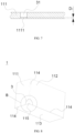
- FIG. 7 is a partially cross-sectional view of the first wall 111 shown in FIG. 5 .
- the first groove segment 31 is disposed on the first wall 111 to form a first weak portion 1111, where thickness of the first weak portion 1111 is D 1 , satisfying 0.05 mm ⁇ D 1 ⁇ 0.7 mm.
- the thickness of the first weak portion 1111 is a thickness that needs to be broken when the indentation groove 3 cracks for pressure relief.
- the thickness of the first weak portion 1111 may be uniform or non-uniform. Referring to FIG. 7 , if the thickness of the first weak portion 1111 is uniform, D 1 is the thickness of the first weak portion 1111 at any position. If the thickness of the first weak portion 1111 is non-uniform, D 1 is the minimum thickness of the first weak portion 1111.
- D 1 may be any value from 0.05 mm to 0.7 mm, for example, 0.05 mm, 0.1 mm, 0.15 mm, 0.2 mm, 0.25 mm, 0.3 mm, 0.35 mm, 0.4 mm, 0.45 mm, 0.5 mm, 0.55 mm, 0.6 mm, 0.65 mm, or 0.7 mm.
- the thickness of the first weak portion 1111 being set within an appropriate range can reduce the risk of insufficient bursting pressure due to excessively small thickness and inadequate strength of the first weak portion 1111, and can also reduce the risk of the indentation groove 3 failing to crack for pressure relief in a timely manner due to excessively large thickness of the first weak portion 1111.
- FIG. 8 is a schematic structural diagram of the housing 1 according to some other embodiments of this application.
- the indentation groove 3 further includes a second groove segment 32, where the second groove segment 32 is disposed on the second wall 112, and two ends of the second groove segment 32 extend to two of the edge portions 114 located at edges of the second wall 112 respectively.
- the second groove segment 32 may be arc-shaped, strip-shaped, zigzag-shaped, or the like.
- the second groove segment 32 may be disposed on an inner surface of the second wall 112 or on an outer surface of the second wall 112.
- An end of the first groove segment 31 may be connected to or spaced apart from an end of the second groove segment 32.
- the two ends of the second groove segment 32 extend to the two edge portions 114 located at the edges of the second wall 112 respectively.
- the two edge portions 114 of the second wall 112 can reinforce the region in which the second groove segment 32 is disposed on the housing 1, thereby improving fatigue resistance of the region in which the second groove segment 32 is disposed on the housing 1 and prolonging the service life of the battery cell 10.
- the second groove segment 32 is disposed on the second wall 112, so that when the battery cell 10 relieves the pressure, the housing 1 can crack at the positions of the first groove segment 31 and the second groove segment 32, increasing a pressure relief area of a pressure relief apparatus, thereby improving the pressure relief efficiency.
- FIG. 9 is a partially enlarged view of position B in FIG. 8 of this application.
- the second groove segment 32 is arc-shaped.
- the second groove segment 32 may be referred to as arc-shaped.
- the first groove segment 31 may also be arc-shaped, and each portion of the first groove segment 31 and the second groove segment 32 has basically the same distance to the vertex 115, so that each portion of the first groove segment 31 and the second groove segment 32 has roughly equal difficulty in bursting.
- each portion of the second groove segment 32 has the same distance to the vertex 115, so that each portion of the second groove segment 32 has roughly equal difficulty in bursting, allowing the second groove segment 32 to crack in a timely manner, thereby improving the pressure relief efficiency.
- FIG. 10 is a schematic structural diagram of the housing 1 according to still some other embodiments of this application
- FIG. 11 is a partially enlarged schematic structural diagram of position C in FIG. 10 of this application.
- the second groove segment 32 is connected to the first groove segment 31.
- connection position of the second groove segment 32 and the first groove segment 31 is located at the edge portion 114 where the first wall 111 and the second wall 112 are connected.
- the housing 1 can partially open along a direction X with the first groove segment 31 and the second groove segment 32 as boundaries, increasing the pressure relief area, thereby improving the pressure relief efficiency.
- FIG. 12 is a partially cross-sectional view of the second wall 112 shown in FIG. 8 or FIG. 10 .
- the first groove segment 31 is disposed on the first wall 111 to form a first weak portion 1111
- the second groove segment 32 is disposed on the second wall 112 to form a second weak portion 1121; where thickness of the first weak portion 1111 is equal to thickness of the second weak portion 1121.
- a thickness that needs to be broken of the position at which the second groove segment 32 is disposed on the housing body 11 may be referred to as the thickness of the second weak portion 1121.
- the position at which the first groove segment 31 is disposed on the housing body 11 and the position at which the second groove segment 32 is disposed on the housing body 11 have the same thickness that needs to be broken, which may be referred to as the thickness of the first weak portion 1111 being equal to the thickness of the second weak portion 1121.
- the first weak portion 1111 and the second weak portion 1121 have roughly equal difficulty in cracking, allowing the first weak portion 1111 and the second weak portion 1121 to crack synchronously during pressure relief.
- FIG. 12 is a partially cross-sectional view of the second wall 112 shown in FIG. 8 or FIG. 10 .
- the second groove segment 32 is disposed on the second wall 112 to form a second weak portion 1121; where thickness of the second weak portion 1121 is D 2 , satisfying 0.05 mm ⁇ D 2 ⁇ 0.7 mm.
- the thickness of the second weak portion 1121 may be uniform or non-uniform. Referring to FIG. 12 , if the thickness of the first weak portion 1111 is uniform, D 2 is the thickness of the first weak portion 1111 at any position. If the thickness of the first weak portion 1111 is non-uniform, D 2 is the minimum thickness of the first weak portion 1111.
- D 2 may be any value from 0.05 mm to 0.7 mm, for example, 0.05 mm, 0.1 mm, 0.15 mm, 0.2 mm, 0.25 mm, 0.3 mm, 0.35 mm, 0.4 mm, 0.45 mm, 0.5 mm, 0.55 mm, 0.6 mm, 0.65 mm, or 0.7 mm.
- the thickness of the second weak portion 1121 being set within an appropriate range can reduce the risk of insufficient bursting pressure due to excessively small thickness and inadequate strength of the second weak portion 1121, and can also reduce the risk of the indentation groove 3 failing to crack for pressure relief in a timely manner due to excessively large thickness of the second weak portion 1121.
- FIG. 13 is a schematic structural diagram of the housing 1 according to yet some other embodiments of this application.
- the indentation groove 3 includes a third groove segment 33, where the third groove segment 33 is disposed on the third wall 113, and two ends of the third groove segment 33 extend to two of the edge portions 114 located at edges of the third wall 113 respectively.
- the third groove segment 33 may be arc-shaped, strip-shaped, zigzag-shaped, or the like.
- the third groove segment 33 may be disposed on an inner surface of the third wall 113 or on an outer surface of the third wall 113.
- the first groove segment 31, the second groove segment 32, and the third groove segment 33 may all be not connected, or two of the groove segments may be connected but spaced apart from the remaining groove segment, or the three groove segments may be connected end to end in sequence.
- two ends of the third groove segment 33 are connected to the first groove segment 31 and the second groove segment 32 respectively, and an end of the first groove segment 31 facing away from the third groove segment 33 is connected to an end of the second groove segment 32 facing away from the third groove segment 33.
- the two ends of the third groove segment 33 extend to the two edge portions 114 located at the edges of the third wall 113 respectively.
- the two edge portions 114 of the third wall 113 can reinforce the region in which the third groove segment 33 is disposed on the housing 1, thereby improving fatigue resistance of the region in which the third groove segment 33 is disposed on the housing 1 and prolonging the service life of the battery cell 10.
- the third groove segment 33 is disposed on the third wall 113, so that when the battery cell 10 relieves the pressure, the housing 1 can crack at the positions of the first groove segment 31, the second groove segment 32, and the third groove segment 33, increasing the pressure relief area of the pressure relief apparatus, thereby improving the pressure relief efficiency.
- FIG. 14 is a partially enlarged schematic structural diagram of position D in FIG. 13 of this application.
- the third groove segment 33 is arc-shaped.
- the third groove segment 33 may be referred to as arc-shaped.
- first groove segment 31, the second groove segment 32, and the third groove segment 33 may all be arc-shaped, and each portion of the first groove segment 31, the second groove segment 32, and the third groove segment 33 has basically the same distance to the vertex 115, so that each portion of the first groove segment 31, the second groove segment 32, and the third groove segment 33 has roughly equal difficulty in bursting.
- each portion of the third groove segment 33 has the same distance to the vertex 115, so that each portion of the third groove segment 33 has roughly equal difficulty in bursting, allowing the third groove segment 33 to crack in a timely manner, thereby improving the pressure relief efficiency.
- the second groove segment 32, the first groove segment 31, and the third groove segment 33 can crack in a timely manner, allowing the housing 1 to discharge gas in a timely manner while increasing the pressure relief area of the housing 1.
- FIG. 15 is a schematic structural diagram of the housing 1 according to other embodiments of this application
- FIG. 16 is a partially enlarged schematic structural diagram of position E in FIG. 15 .
- Two ends of the third groove segment 33 are connected to the first groove segment 31 and the second groove segment 32 respectively, and an end of the first groove segment 31 facing away from the third groove segment 33 is connected to or spaced apart from an end of the second groove segment 32 facing away from the third groove segment 33.
- the end of the first groove segment 31 facing away from the third groove segment 33 is spaced apart from the end of the second groove segment 32 facing away from the third groove segment 33, and the first groove segment 31 and the second groove segment 32 are spaced apart by the edge portion 114.
- the region jointly defined by the first groove segment 31, the second groove segment 32, and the third groove segment 33 can detach to open for pressure relief, allowing the housing 1 to have a large pressure relief area when relieving the pressure, thereby improving the pressure relief efficiency.
- the region jointly defined by the first groove segment 31, the second groove segment 32, and the third groove segment 33 can flip along a direction Y to open for pressure relief.
- the housing 1 has a large pressure relief area, the portion of the housing 1 that flips along the direction Y does not detach from the main body of the housing 1, reducing the probability of secondary damage to the battery 1000.
- the first groove segment 31 is disposed on the first wall 111 to form a first weak portion 1111
- the second groove segment 32 is disposed on the second wall 112 to form a second weak portion 1121.
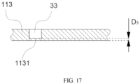
- FIG. 17 is a partially cross-sectional view of the third wall 113 shown in FIG. 13 or FIG. 15 of this application.
- the third groove segment 33 is disposed on the third wall 113 to form a third weak portion 1131, where thickness of the first weak portion 1111, thickness of the second weak portion 1121, and thickness of the third weak portion 1131 are equal.
- the thickness of the third weak portion 1131 is a thickness that needs to be broken of the position at which the third groove segment 33 is disposed on the housing body 11 when the indentation groove 3 cracks for pressure relief.
- the position at which the first groove segment 31 is disposed on the housing body 11, the position at which the second groove segment 32 is disposed on the housing body 11, and the position at which the third groove segment 33 is disposed on the housing body 11 have the same thickness that needs to be broken, which may be referred to as the thickness of the first weak portion 1111, the thickness of the second weak portion 1121, and the thickness of the third weak portion 1131 being equal.
- the first weak portion 1111, the second weak portion 1121, and the third weak portion 1131 have roughly equal difficulty in cracking, allowing the first weak portion 1111, the second weak portion 1121, and the third weak portion 1131 to crack synchronously during pressure relief.
- the third groove segment 33 is disposed on the third wall 113 to form a third weak portion 1131, where thickness of the third weak portion 1131 is D 3 , satisfying 0.05 mm ⁇ D 3 ⁇ 0.7 mm.
- the thickness of the third weak portion 1131 may be uniform or non-uniform. Referring to FIG. 17 , if the thickness of the third weak portion 1131 is uniform, D 3 is the thickness of the third weak portion 1131 at any position. If the thickness of the third weak portion 1131 is non-uniform, D 3 is the minimum thickness of the third weak portion 1131.
- D 3 may be any value from 0.05 mm to 0.7 mm, for example, 0.05 mm, 0.1 mm, 0.15 mm, 0.2 mm, 0.25 mm, 0.3 mm, 0.35 mm, 0.4 mm, 0.45 mm, 0.5 mm, 0.55 mm, 0.6 mm, 0.65 mm, or 0.7 mm.
- the thickness of the third weak portion 1131 being set within an appropriate range can reduce the risk of insufficient bursting pressure due to excessively small thickness and inadequate strength of the third weak portion 1131, and can also reduce the risk of the indentation groove 3 failing to crack for pressure relief in a timely manner due to excessively large thickness of the third weak portion 1131.
- the housing 1 includes an accommodating space formed by a plurality of walls, where the accommodating space is used to accommodate an electrode assembly 2, the accommodating space has an opening, and the opening is opposite the third wall 113.
- the hollow cuboid housing 1 is used as an example.
- the internal space of the housing body 11 is used to accommodate the electrode assembly 2, the housing body 11 is provided with an opening on a side opposite the bottom wall, and the end cover 12 is connected to the housing 1 at the opening of the housing 1 to form the enclosed housing 1 of the battery cell 10.
- Such a housing 1 can accommodate the electrode assembly 2 through the opening, resulting in low assembly difficulty of the electrode assembly 2.
- first wall 111, the second wall 112, and the third wall 113 are connected to each other in pairs via arc walls, the arc walls being the edge portions 114.
- the housing 1 is a cuboid.
- the indentation groove 3 is provided on an outer surface of the housing 1.
- the indentation groove 3 being provided on the outer surface of the housing 1 can reduce processing difficulty of the indentation groove 3.
- this application provides a battery cell 10 including the housing 1 according to the foregoing embodiments.
- this application provides a battery 1000 including a box configured to accommodate a battery cell 10 and the battery cell 10 according to the foregoing embodiments.
- this application provides an electric device including the battery 1000 according to the foregoing embodiments.
- this application provides a hollow cuboid housing 1.
- the housing 1 includes a housing body 11 and a cover plate.
- a plurality of walls of the housing body 11 include a first wall 111, a second wall 112, and a third wall 113.
- An indentation groove 3 is provided on an outer surface of the housing 1.
- the indentation groove 3 includes a first groove segment 31 disposed on the first wall 111, a second groove segment 32 disposed on the second wall 112, and a third groove segment 33 disposed on the third wall 113.
- Two ends of the first groove segment 31 extend to two edge portions 114 located at edges of the first wall 111 respectively, two ends of the second groove segment 32 extend to two edge portions 114 located at edges of the second wall 112 respectively, and two ends of the third groove segment 33 extend to two edge portions 114 located at edges of the third wall 113 respectively.
- the first groove segment 31, the second groove segment 32, and the third groove segment 33 are all arc-shaped. Two ends of the third groove segment 33 are connected to the first groove segment 31 and the second groove segment 32 respectively. An end of the first groove segment 31 facing away from the third groove segment 33 is spaced apart from an end of the second groove segment 32 facing away from the third groove segment 33.
- the region jointly defined by the first groove segment 31, the second groove segment 32, and the third groove segment 33 can flip along a direction Y to open for pressure relief.
Landscapes
- Chemical & Material Sciences (AREA)
- Chemical Kinetics & Catalysis (AREA)
- Electrochemistry (AREA)
- General Chemical & Material Sciences (AREA)
- Sealing Battery Cases Or Jackets (AREA)
- Gas Exhaust Devices For Batteries (AREA)
Abstract
Description
- This application claims priority to
Chinese Patent Application No. 202211068028.X, filed on September 02, 2022 - This application relates to the field of battery technologies, and specifically, to a housing, a battery cell, a battery, and an electric device.
- Batteries are widely used in electronic devices such as electric bicycles, electric vehicles, electric airplanes, and electric ships.
- In the development of battery technology, in addition to the performance improvement of battery cells, the service life of battery cells is also an issue that needs consideration.
- Therefore, how the service life of battery cells is prolonged is an urgent problem that needs to be solved in battery technology.
- In view of the foregoing problem, this application provides a housing, a battery cell, a battery, and an electric device, so as to effectively prolong service life of the battery cell.
- According to a first aspect, this application provides a housing. The housing has at least three edge portions intersecting at a same vertex; and the housing is provided with an indentation groove, the indentation groove intersecting with at least two of the edge portions.
- In the technical solution of the embodiments of this application, the housing has at least three edge portions intersecting at a same vertex, and the indentation groove intersects with at least two of the edge portions, such that the region in which the indentation groove is provided on the housing is located near the at least two edge portions of the housing. Because the region near the edge portion of the housing has strong deformation resistance, the probability of abnormal cracking of the indentation groove due to creeping of the region in which the indentation groove is provided on the housing is reduced, prolonging service life of the housing, thereby prolonging service life of the battery cell.
- In some embodiments, the housing in the embodiments of this application includes a first wall, a second wall, and a third wall, where the first wall, the second wall, and the third wall are connected to each other in pairs to form three of the edge portions intersecting at the vertex. The housing having three edge portions intersecting at a same vertex may be a cuboid, a tetrahedron, or of another shape, and such a housing has advantages such as ease of processing and mass production.
- In some embodiments, the indentation groove includes a first groove segment, where the first groove segment is disposed on the first wall, and two ends of the first groove segment extend to two of the edge portions located at edges of the first wall respectively. The two edge portions of the first wall can reinforce the region in which the first groove segment is disposed on the housing, thereby improving fatigue resistance of the region in which the first groove segment is disposed on the housing and prolonging the service life of the battery cell.
- In some embodiments, the first groove segment is arc-shaped. With such a design, each portion of the first groove segment has basically the same distance to the vertex, so that each portion of the first groove segment has roughly equal difficulty in bursting, allowing the first groove segment to crack in a timely manner, thereby improving pressure relief efficiency.
- In some embodiments, the first groove segment is disposed on the first wall to form a first weak portion, where thickness of the first weak portion is D1, satisfying 0.05 mm ≤ D1 ≤ 0.7 mm. The thickness of the first weak portion being set within an appropriate range can reduce the risk of insufficient bursting pressure due to excessively small thickness and inadequate strength of the first weak portion, and can also reduce the risk of the indentation groove failing to crack for pressure relief in a timely manner due to excessively large thickness of the first weak portion.
- In some embodiments, the indentation groove further includes a second groove segment, where the second groove segment is disposed on the second wall, and two ends of the second groove segment extend to two of the edge portions located at edges of the second wall respectively. The two ends of the second groove segment extend to the two edge portions located at the edges of the second wall respectively. The two edge portions of the second wall can reinforce the region in which the second groove segment is disposed on the housing, thereby improving fatigue resistance of the region in which the second groove segment is disposed on the housing and prolonging the service life of the battery cell. In addition, with the first groove segment disposed on the first wall, the second groove segment is disposed on the second wall, so that when the battery cell relieves the pressure, the housing can crack at the positions of the first groove segment and the second groove segment, increasing a pressure relief area of a pressure relief apparatus, thereby improving the pressure relief efficiency.
- In some embodiments, the second groove segment is arc-shaped. With such a design, each portion of the second groove segment has basically the same distance to the vertex, so that each portion of the second groove segment has roughly equal difficulty in bursting, allowing the second groove segment to crack in a timely manner, thereby improving the pressure relief efficiency.
- In some embodiments, the second groove segment is connected to the first groove segment. With such a design, the housing can partially open with the first groove segment and the second groove segment as boundaries, increasing the pressure relief area, thereby improving the pressure relief efficiency.
- In some embodiments, the first groove segment is disposed on the first wall to form a first weak portion, and the second groove segment is disposed on the second wall to form a second weak portion; where thickness of the first weak portion is equal to thickness of the second weak portion. With such a design, the first weak portion and the second weak portion have roughly equal difficulty in cracking, allowing the first weak portion and the second weak portion to crack synchronously during pressure relief.
- In some embodiments, the second groove segment is disposed on the second wall to form a second weak portion; where thickness of the second weak portion is D2, satisfying 0.05 mm ≤ D2 ≤ 0.7 mm. The thickness of the second weak portion being set within an appropriate range can reduce the risk of insufficient bursting pressure due to excessively small thickness and inadequate strength of the second weak portion, and can also reduce the risk of the indentation groove failing to crack for pressure relief in a timely manner due to excessively large thickness of the second weak portion.
- In some embodiments, the indentation groove includes a third groove segment, where the third groove segment is disposed on the third wall, and two ends of the third groove segment extend to two of the edge portions located at edges of the third wall respectively. The two ends of the third groove segment extend to the two edge portions located at the edges of the third wall respectively.
- The two edge portions of the third wall can reinforce the region in which the third groove segment is disposed on the housing, thereby improving fatigue resistance of the region in which the third groove segment is disposed on the housing and prolonging the service life of the battery cell.
- In addition, with the first groove segment disposed on the first wall and the second groove segment disposed on the second wall, the third groove segment is disposed on the third wall, so that when the battery cell relieves the pressure, the housing can crack at the positions of the first groove segment, the second groove segment, and the third groove segment, increasing the pressure relief area of the pressure relief apparatus, thereby improving the pressure relief efficiency.
- In some embodiments, the third groove segment is arc-shaped. With such a design, each portion of the third groove segment has basically the same distance to the vertex, so that each portion of the third groove segment has roughly equal difficulty in bursting, allowing the third groove segment to crack in a timely manner, thereby improving the pressure relief efficiency.
- In some embodiments, two ends of the third groove segment are connected to the first groove segment and the second groove segment respectively, and an end of the first groove segment facing away from the third groove segment is connected to or spaced apart from an end of the second groove segment facing away from the third groove segment. When the end of the first groove segment facing away from the third groove segment is connected to the end of the second groove segment facing away from the third groove segment, the region jointly defined by the first groove segment, the second groove segment, and the third groove segment can detach to open for pressure relief. When the end of the first groove segment facing away from the third groove segment is spaced apart from the end of the second groove segment facing away from the third groove segment, the region jointly defined by the first groove segment, the second groove segment, and the third groove segment can flip to open for pressure relief.
- In some embodiments, the first groove segment is disposed on the first wall to form a first weak portion, the second groove segment is disposed on the second wall to form a second weak portion, and the third groove segment is disposed on the third wall to form a third weak portion, where thickness of the first weak portion, thickness of the second weak portion, and thickness of the third weak portion are equal. With such a design, the first weak portion, the second weak portion, and the third weak portion have roughly equal difficulty in cracking, allowing the first weak portion, the second weak portion, and the third weak portion to crack synchronously during pressure relief.
- In some embodiments, the third groove segment is disposed on the third wall to form a third weak portion, where thickness of the third weak portion is D3, satisfying 0.05 mm ≤ D3 ≤ 0.7 mm. The thickness of the third weak portion being set within an appropriate range can reduce the risk of insufficient bursting pressure due to excessively small thickness and inadequate strength of the third weak portion, and can also reduce the risk of the indentation groove failing to crack for pressure relief in a timely manner due to excessively large thickness of the third weak portion.
- In some embodiments, the housing includes an accommodating space formed by a plurality of walls, where the accommodating space is used to accommodate an electrode assembly, the accommodating space has an opening, and the opening is opposite the third wall. Such a housing can accommodate the electrode assembly through the opening, resulting in low assembly difficulty of the electrode assembly.
- In some embodiments, the first wall, the second wall, and the third wall are connected to each other in pairs via arc walls, the arc walls being the edge portions. Such a housing being subjected to fillet processing facilitates assembly of the housing.
- In some embodiments, the housing is a cuboid.
- In some embodiments, the indentation groove is provided on an outer surface of the housing. With such a design, processing difficulty of the indentation groove is reduced.
- According to a second aspect, this application provides a battery cell including the housing according to the foregoing embodiments.
- According to a third aspect, this application provides a battery including a box configured to accommodate a battery cell and the battery cell according to the foregoing embodiments.
- According to a fourth aspect, this application provides an electric device including the battery according to the foregoing embodiments.
- The foregoing description is merely an overview of the technical solutions of this application. For a better understanding of the technical means in this application such that they can be implemented according to the content of the specification, and to make other objectives, features, and advantages of this application more obvious and easier to understand, the following describes specific embodiments of this application.
- Persons of ordinary skill in the art can clearly understand various other advantages and benefits by reading the detailed description of the preferred embodiments below. The accompanying drawings are merely intended to illustrate the preferred embodiments, and should not be construed as any limitation on this application. In addition, in all the accompanying drawings, the same reference signs represent the same components. In the accompanying drawings:
-
FIG. 1 is a schematic structural diagram of a vehicle according to some embodiments of this application; -
FIG. 2 is an exploded view of a battery according to some embodiments of this application; -
FIG. 3 is a schematic structural diagram of a battery module according to some embodiments of this application; -
FIG. 4 is an exploded view of a battery cell according to some embodiments of this application; -
FIG. 5 is a schematic structural diagram of a housing according to some embodiments of this application; -
FIG. 6 is a partially enlarged view of position A inFIG. 5 ; -
FIG. 7 is a partially cross-sectional view of a first wall shown inFIG. 5 ; -
FIG. 8 is a schematic structural diagram of a housing according to some other embodiments of this application; -
FIG. 9 is a partially enlarged view of position B inFIG. 8 ; -
FIG. 10 is a schematic structural diagram of a housing according to still some other embodiments of this application; -
FIG. 11 is a partially enlarged schematic structural diagram of position C inFIG. 10 ; -
FIG. 12 is a partially cross-sectional view of a second wall shown inFIG. 8 orFIG. 10 ; -
FIG. 13 is a schematic structural diagram of a housing according to yet some other embodiments of this application; -
FIG. 14 is a partially enlarged schematic structural diagram of position D inFIG. 13 of this application; -
FIG. 15 is a schematic structural diagram of a housing according to other embodiments of this application; -
FIG. 16 is a partially enlarged schematic structural diagram of position E inFIG. 15 ; and -
FIG. 17 is a partially cross-sectional view of a third wall shown inFIG. 13 orFIG. 15 . - Reference signs in the specific embodiments are described as follows:
- 10000. vehicle; 3000. controller; 4000. motor;
- 1000. battery; 101. first portion; 102. second portion;
- 100. battery module;
- 10. battery cell;
- 1. housing; 11. housing body; 12. end cover; 2. electrode assembly; 3. indentation groove; 4. electrode terminal; 5. connecting member;
- 111. first wall; 1111. first weak portion; 112. second wall; 1121. second weak portion; 113. third wall; 1131. third weak portion; 114. edge portion; 115. vertex;
- 31. first groove segment; 32. second groove segment; and 33. third groove segment.
- The following describes in detail embodiments of technical solutions of this application with reference to the accompanying drawings. The following embodiments are merely used to describe the technical solutions in this application more clearly, and therefore are merely used as examples and do not constitute any limitation on the protection scope of this application.
- Unless otherwise defined, all technical and scientific terms used herein shall have the same meanings as commonly understood by persons skilled in the art to which this application relates. The terms used herein are intended to merely describe the specific embodiments rather than to limit this application. The terms "include", "comprise", and "have" and any other variations thereof in the specification, claims, and brief description of drawings of this application are intended to cover non-exclusive inclusions.
- In the description of the embodiments of this application, the technical terms "first", "second", and the like are merely intended to distinguish between different objects, and shall not be understood as any indication or implication of relative importance or any implicit indication of the number, specific sequence, or primary-secondary relationship of the technical features indicated. In the description of the embodiments of this application, "a plurality of" means more than two, unless otherwise specifically defined.
- In this specification, reference to "embodiment" means that specific features, structures, or characteristics described with reference to the embodiment may be incorporated in at least one embodiment of this application. The word "embodiment" appearing in various places in the specification does not necessarily refer to the same embodiment or an independent or alternative embodiment that is exclusive of other embodiments. Persons skilled in the art explicitly and implicitly understand that the embodiments described herein may be combined with other embodiments.
- In the description of the embodiments of this application, the term "a plurality of" means more than two (inclusive). Similarly, "a plurality of groups" means more than two (inclusive) groups, and "a plurality of pieces" means more than two (inclusive) pieces.
- In the description of the embodiments of this application, the orientations or positional relationships indicated by the technical terms "center", "longitudinal", "transverse", "length", "width", "thickness", "upper", "lower", "front", "rear", "left", "right", "vertical", "horizontal", "top", "bottom", "inside", "outside", "clockwise", "counterclockwise", "axial", "radial", "circumferential", and the like are based on the orientations or positional relationships as shown in the accompanying drawings. These terms are merely for ease and brevity of the description of the embodiments of this application rather than indicating or implying that the apparatuses or elements mentioned must have specific orientations or must be constructed or manipulated according to specific orientations, and therefore shall not be construed as any limitations on the embodiments of this application.
- In the description of the embodiments of this application, unless otherwise specified and defined explicitly, the technical terms "mount", "connect", "join", and "fix" should be understood in their general senses. For example, they may refer to a fixed connection, a detachable connection, or an integral connection, may refer to a mechanical connection or an electrical connection, and may refer to a direct connection, an indirect connection via an intermediate medium, an internal communication between two elements, or an interaction between two elements. Persons of ordinary skill in the art can understand specific meanings of these terms in the embodiments of this application as appropriate to specific situations.
- The batteries mentioned in the art can be classified into primary batteries and rechargeable batteries based on whether the batteries are rechargeable. Currently, common types of rechargeable batteries include lead-acid battery, nickel-hydrogen battery, and lithium-ion battery. At present, lithium-ion batteries are widely used in battery electric vehicles and hybrid electric vehicles. The lithium-ion batteries used for this purpose have a relatively low capacity but a relatively large output and charging current and a relatively long service life, although the cost is relatively high.
- The battery described in the embodiments of this application is a rechargeable battery. The following mainly uses the lithium-ion battery as an example to describe the embodiments disclosed in this application. It should be understood that the embodiments disclosed in this application are applicable to any other suitable type of rechargeable battery. The battery mentioned in the embodiments disclosed in this application may be directly or indirectly applied to an appropriate apparatus to supply power to the apparatus.
- The battery mentioned in the embodiments disclosed in this application is a single physical module that includes one or more battery cells for providing a predetermined voltage and capacity. The battery cell is a basic unit in a battery, and can be typically categorized into three types depending on its packaging: cylindrical battery cell, cuboid battery cell, and pouch battery cell. The following will mainly focus on the cuboid battery cell. It should be understood that the embodiments described below are also applicable to the cylindrical battery cell or pouch battery cell in some aspects.
- The battery cell includes a positive electrode plate, a negative electrode plate, an electrolyte, and a separator. The lithium-ion battery cell mainly relies on migration of lithium ions between the positive electrode plate and the negative electrode plate to work. A film structure with three layers of materials in the cylindrical battery cell is wound into a cylindrical electrode assembly, and a film structure in the cuboid battery cell is wound or stacked into a roughly cuboid electrode assembly.
- In a typical battery cell structure, the battery cell includes a housing, an electrode assembly, and an electrolyte. The electrode assembly is accommodated in the housing of the battery cell, and the electrode assembly includes a positive electrode plate, a negative electrode plate, and a separator. The housing includes a housing and an end cover. The housing includes an accommodating chamber formed by a plurality of walls, and an opening. The end cover is disposed at the opening to seal the accommodating chamber. In addition to the electrode assembly, the accommodating chamber further accommodates the electrolyte. The positive electrode plate and the negative electrode plate in the electrode assembly each include a tab. To reduce the risk of fusing due to a large current passing through, a plurality of positive electrode tabs are provided and stacked together, and a plurality of negative electrode tabs are provided and stacked together. The tab is electrically connected to an electrode terminal outside the battery cell via a connecting member, and the electrode terminal generally includes a positive electrode terminal and a negative electrode terminal. For the cuboid battery cell, the electrode terminal is generally disposed on the end cover. A plurality of battery cells are connected in series and/or in parallel through electrode terminals for various application scenarios.
- In some high-power application scenarios such as an electric vehicle, the application of the battery includes three levels: a battery cell, a battery module, and a battery. The battery module is formed by electrically connecting a specific quantity of battery cells and putting the battery cells into a frame to protect the battery cells from external impact, heat, vibration, and the like. The battery is a final state of a battery system assembled in an electric vehicle. The battery generally includes a box for packaging one or more battery cells. The box generally consists of a cover body and a box housing.
- For the battery cell, main safety hazards are in the charging and discharging processes. In addition, a suitable ambient temperature also needs to be designed. To effectively reduce the risk of unnecessary losses, at least triple protection measures are generally provided for the battery cell. Specifically, the protection measures include at least a switch element, an appropriately selected separator material, and a housing.
- For the housing, a pressure relief groove may be disposed on the housing to form a weak portion, and the housing relieves pressure after the weak portion cracks.
- In normal use of the battery cell, the weak portion of the housing may experience abnormal cracking. Generally, the pressure relief groove is provided in the middle region of a wall of the housing, and in actual operation of the battery cell, the internal pressure of the housing varies with the ambient temperature. In the process of continuous changes in the internal pressure of the battery cell, the housing is repeatedly impacted by the pressure. As a result, the weak portion of the housing is likely to creep, causing the pressure relief groove to crack prematurely, thereby reducing service life of the battery cell.
- In view of this, to solve the problem of reduced service life of the battery cell caused by the premature cracking of the pressure relief groove due to creeping of the weak portion of the housing, this application provides a housing. The pressure relief groove on the housing intersects with at least two edge portions of the housing, so that the region in which the pressure relief groove is provided on the housing has improved deformation resistance, reducing the probability of premature cracking of the pressure relief groove due to creeping of the weak portion formed after the pressure relief groove is provided on the housing.
- The technical solution described in the embodiments of this application is applicable to battery cells, batteries, and electric devices using a battery.
- The electric device includes but is not limited to an electric bicycle, an electric vehicle, a ship, and a spacecraft. For example, the spacecraft includes an airplane, a rocket, a space shuttle, a spaceship, and the like.
- For ease of description, an electric apparatus of an embodiment of this application being a
vehicle 10000 is used as an example for description of the following embodiments. - For example,
FIG. 1 is a schematic structural diagram of avehicle 10000 according to some embodiments of this application. Thevehicle 10000 may be a fossil fuel vehicle, a natural gas vehicle, or a new energy vehicle. The new energy vehicle may be a battery electric vehicle, a hybrid electric vehicle, a range-extended electric vehicle, or the like. Amotor 4000, acontroller 3000, and abattery 1000 may be disposed inside thevehicle 10000, where thecontroller 3000 is configured to control thebattery 1000 to supply power to themotor 4000. For example, thebattery 1000 may be disposed at the bottom, front, or rear of thevehicle 10000. Thebattery 1000 can be configured to supply power to thevehicle 10000. For example, thebattery 1000 can be used as an operational power source for thevehicle 10000 which is configured for a circuit system of thevehicle 10000, for example, to satisfy power needs of start, navigation, and running of thevehicle 10000. In another embodiment of this application, thebattery 1000 may be used not only as the operational power source for thevehicle 10000, but also as a driving power source for thevehicle 10000, replacing or partially replacing fossil fuel or natural gas to provide driving traction for thevehicle 10000. - To meet different power usage requirements, the
battery 1000 may include a plurality ofbattery cells 10, and the plurality ofbattery cells 10 may be connected in series, parallel, or series-parallel, where being connected in series-parallel means a combination of series and parallel connections. Thebattery 1000 may also be referred to as a battery pack. Optionally, a plurality ofbattery cells 10 may first be connected in series, parallel, or series-parallel to constitute abattery module 100, and then a plurality ofbattery modules 100 are connected in series, parallel, or series-parallel to constitute abattery 1000. In other words, the plurality ofbattery cells 10 may directly constitute thebattery 1000, or may first constitute thebattery modules 100 which then constitute thebattery 1000. - For example, referring to
FIG. 2, FIG. 2 is an exploded view of abattery 1000 according to some embodiments of this application. Thebattery 1000 may include a plurality ofbattery cells 10. Thebattery 1000 may further include a box (or referred to as a cover body), the inside of the box is a hollow structure, and the plurality ofbattery cells 10 are accommodated in the box. As shown inFIG. 2 , the box includes two portions, which are herein referred to as afirst portion 101 and asecond portion 102 respectively. Thefirst portion 101 and thesecond portion 102 are snap-fitted together. Shapes of thefirst portion 101 and thesecond portion 102 may be determined based on a shape in which the plurality ofbattery cells 10 are combined, and thefirst portion 101 and thesecond portion 102 each may have an opening. For example, thefirst portion 101 and thesecond portion 102 each may be a hollow cuboid with only one surface having an opening, the opening of thefirst portion 101 is opposite the opening of thesecond portion 102, and thefirst portion 101 and thesecond portion 102 are snap-fitted to form a box with an enclosed chamber. The plurality ofbattery cells 10 are connected in parallel, series, or series-parallel and then placed into the box formed by snap-fitting thefirst portion 101 and thesecond portion 102. - Optionally, the
battery 1000 may further include other structures. Details are not described herein again. For example, the battery may further include a busbar, where the busbar is configured to implement an electrical connection between the plurality ofbattery cells 10, for example, in parallel, series, or series-parallel. Specifically, the busbar may implement the electrical connection between thebattery cells 10 by connectingelectrode terminals 4 of thebattery cells 10. Further, the busbar may be fixed to theelectrode terminals 4 of thebattery cells 10 by welding. Electrical energy of the plurality ofbattery cells 10 may be further led out by a conductive mechanism that passes through the box. Optionally, the conductive mechanism may also belong to the busbar. - Based on different power demands, the
battery cells 10 can be set in any quantity. The plurality ofbattery cells 10 may be connected in series, parallel, or series-parallel to achieve large capacity or power. Because the quantity ofbattery cells 10 included in eachbattery 1000 may be large, for ease of mounting, thebattery cells 10 may be arranged in groups, and each group ofbattery cells 10 forms abattery module 100. The quantity ofbattery cells 10 included in thebattery module 100 is not limited, and may be set as required. For example,FIG. 3 is a schematic structural diagram of abattery module 100 according to some embodiments of this application. Thebattery 1000 may include a plurality ofbattery modules 100, and thesebattery modules 100 may be connected in series, parallel, or series-parallel. - Referring to
FIG. 4, FIG. 4 is an exploded view of abattery cell 10 according to some embodiments of this application. Thebattery cell 10 includes one ormore electrode assemblies 2 and ahousing 1. Thehousing 1 may include ahousing body 11. A plurality of wall portions of thehousing body 11, namely, a plurality of wall portions of thehousing 1, enclose a chamber, and the chamber can be used to accommodate theelectrode assemblies 2. Thehousing body 11 is determined based on a shape in which the one ormore electrode assemblies 2 are combined. For example, thehousing body 11 may be a hollow cuboid, cube, or polyhedra, and one surface of thehousing body 11 has an opening such that the one ormore electrode assemblies 2 can be put into thehousing body 11. Thehousing body 11 has five wall portions, including four side walls and one bottom wall. The four side walls are disposed on the bottom wall and enclose a chamber together with the bottom wall. An included angle between two adjacent side walls of the four side walls is ninety degrees, and included angles between the side walls and the bottom wall are ninety degrees. Thehousing 1 may further include an end cover 12. It should be noted that the wall portions of thehousing body 11 and the end cover 12 may all be referred to as the wall portions of thehousing 1. For example, when thehousing body 11 is a hollow cuboid or cube, one plane of thehousing body 11 is an opening surface, which means that the plane has no wall portion such that the inside and the outside of thehousing body 11 are communicated. The end cover 12 covers the opening and is connected to thehousing body 11 to form an enclosed chamber for placing theelectrode assemblies 2. Thehousing body 11 is filled with an electrolyte, for example, a liquid electrolyte. - The
battery cell 10 may further include twoelectrode terminals 4, and the twoelectrode terminals 4 may be disposed on the end cover 12. The end cover 12 is generally in a shape of a flat plate, and the twoelectrode terminals 4 are fixed on a flat surface of the end cover 12. The twoelectrode terminals 4 are apositive electrode terminal 4 and anegative electrode terminal 4 respectively. Eachelectrode terminal 4 is correspondingly provided with a connectingmember 5, which is also referred to as a current collecting member and is located between the end cover 12 and anelectrode assembly 2 for electrically connecting theelectrode assembly 2 and theelectrode terminal 4. - In the
battery cell 10, one ormore electrode assemblies 2 may be provided based on actual use needs. As shown inFIG. 4 , thebattery cell 10 is provided with a plurality ofindependent electrode assemblies 2. - According to some embodiments of this application, referring to
FIG. 5, FIG. 5 is a schematic structural diagram of ahousing 1 according to some embodiments of this application. This application provides ahousing 1, where thehousing 1 has at least threeedge portions 114 intersecting at asame vertex 115, and thehousing 1 is provided with anindentation groove 3 intersecting with at least two of theedge portions 114. - The
housing 1 may be a hollow cuboid, a hollow regular tetrahedron, a hollow frustum, a hollow regular dodecahedron, a hollow pyramid, or the like. - The position at which the at least three
edge portions 114 of thehousing 1 intersect may be referred to as thevertex 115. - If the
housing 1 is a hollow cuboid, a hollow regular tetrahedron, a hollow frustum, or a hollow regular dodecahedron, threeedge portions 114 of thehousing 1 intersect at asame vertex 115; and if thehousing 1 is a hollow pyramid, for example, thehousing 1 is a hollow quadrangular pyramid, fourlateral edge portions 114 of thehousing 1 intersect at onevertex 115 of thehousing 1. - The position at which two adjacent wall portions of the
housing 1 are connected may be referred to as theedge portion 114. Thehousing 1 being a hollow cuboid is used as an example, where the position at which two adjacent wall portions are connected forms theedge portion 114. If theindentation groove 3 is provided on an outer surface of the wall portion and outer surfaces of the two adjacent wall portions intersect at an outer edge line, theindentation groove 3 intersecting with the outer edge line should be understood as theindentation groove 3 intersecting with theedge portion 114; and if theindentation groove 3 is provided on an inner surface of the wall portion and inner surfaces of the two adjacent wall portions intersect at an inner edge line, theindentation groove 3 intersecting with the inner edge line should also be understood as theindentation groove 3 intersecting with theedge portion 114. If the two adjacent wall portions are connected via an arc wall, theindentation groove 3 intersecting with the arc wall should also be understood as theindentation groove 3 intersecting with theedge portion 114. - The region in which the
indentation groove 3 is designed on thehousing 1 forms a weak portion, and the weak portion cracks when internal pressure or temperature or another condition of thehousing 1 reaches a threshold, so as to relieve the internal pressure of thehousing 1. - The
indentation groove 3 may be in a plurality of segments or one segment. If theindentation groove 3 is in a plurality of segments, two of the segments may be connected or spaced apart. - The
indentation groove 3 may be arc-shaped, strip-shaped, O-shaped, zigzag-shaped, or the like. - The
indentation groove 3 may be formed on thehousing 1 through various methods, such as stamping or milling. - The
housing 1 has at least threeedge portions 114 intersecting at asame vertex 115, and theindentation groove 3 intersects with at least two of theedge portions 114, such that the region in which theindentation groove 3 is provided on thehousing 1 is located near the at least twoedge portions 114 of thehousing 1. Because the region near theedge portion 114 of thehousing 1 has strong deformation resistance, the probability of abnormal cracking of theindentation groove 3 due to creeping of the region in which theindentation groove 3 is provided on thehousing 1 is reduced, prolonging service life of thehousing 1, thereby prolonging service life of thebattery cell 10. - The
edge portion 114 of thehousing body 11 has the characteristics of high strength and strong deformation resistance, so with theindentation groove 3 arranged near theedge portion 114, the weak portion is less likely to deform when the weak portion of theindentation groove 3 is processed, making it easy to meet design requirements for processing of the weak portion, and allowing for convenient calculation of a pressure required for cracking of the weak portion of theindentation groove 3, thereby reducing difficulty in designing and processing theindentation groove 3. - In normal use of the
battery cell 10, the weak portion is repeatedly impacted by the internal pressure of thehousing 1, so the weak portion being designed near thevertex 115 can reduce the probability of abnormal cracking of theindentation groove 3 due to creeping of the weak portion. When theindentation groove 3 cracks for pressure relief, an inner wall of thehousing 1 near thevertex 115 converges gas, improving pressure relief efficiency. - According to some embodiments of this application, referring to
FIG. 6, FIG. 6 is a partially enlarged view of position A inFIG. 5 of this application. Thehousing 1 includes afirst wall 111, asecond wall 112, and athird wall 113, where thefirst wall 111, thesecond wall 112, and thethird wall 113 are connected to each other in pairs to form three of theedge portions 114 intersecting at thevertex 115. - The
first wall 111, thesecond wall 112, and thethird wall 113 may also be referred to as the wall portions of thehousing 1. - An included angle between two adjacent wall portions of the
first wall 111, thesecond wall 112, and thethird wall 113 may be a right angle, an acute angle, or an obtuse angle. If thehousing 1 is a hollow cuboid, the included angle between two adjacent walls of thefirst wall 111, thesecond wall 112, and thethird wall 113 is a right angle; if thehousing 1 is a hollow pyramid, the included angle between two adjacent walls of thefirst wall 111, thesecond wall 112, and thethird wall 113 is an acute angle; and if thehousing 1 is a hollow regular dodecahedron, the included angle between two adjacent walls of thefirst wall 111, thesecond wall 112, and thethird wall 113 is an obtuse angle. - The hollow
cuboid housing 1 is used as an example. Thehousing 1 has six walls, where thehousing body 11 has five walls, and the other wall is the end cover 12. Thefirst wall 111, thesecond wall 112, and thethird wall 113 may be any three adjacent walls of the six walls. For example, thefirst wall 111, thesecond wall 112, and thethird wall 113 are three adjacent walls of thehousing body 11. InFIG. 6 , thefirst wall 111 and thesecond wall 112 are two adjacent side walls of thehousing body 11, and thethird wall 113 is the bottom wall. - The
housing 1 having threeedge portions 114 intersecting at asame vertex 115 may be a cuboid, a regular tetrahedron, or of another shape, and such ahousing 1 has advantages such as ease of processing and mass production. - According to some embodiments of this application, referring to
FIG. 6 , theindentation groove 3 includes afirst groove segment 31, where thefirst groove segment 31 is disposed on thefirst wall 111, and two ends of thefirst groove segment 31 extend to two of theedge portions 114 located at edges of thefirst wall 111 respectively. - The
first groove segment 31 may be arc-shaped, strip-shaped, zigzag-shaped, or the like. - The
first groove segment 31 may be disposed on an inner surface of thefirst wall 111 or on an outer surface of thefirst wall 111. - The two
edge portions 114 of thefirst wall 111 can reinforce the region in which thefirst groove segment 31 is disposed on thehousing 1, thereby improving fatigue resistance of the region in which thefirst groove segment 31 is disposed on thehousing 1 and prolonging the service life of thebattery cell 10. - According to some embodiments of this application, referring to
FIG. 6 , thefirst groove segment 31 is arc-shaped. - If each portion of the
first groove segment 31 has basically the same distance to thevertex 115, thefirst groove segment 31 may be referred to as arc-shaped. - With such a design, each portion of the
first groove segment 31 has basically the same distance to thevertex 115, so that each portion of thefirst groove segment 31 has roughly equal difficulty in bursting, allowing thefirst groove segment 31 to crack in a timely manner, thereby improving the pressure relief efficiency. - According to some embodiments of this application, referring to
FIG. 7, FIG. 7 is a partially cross-sectional view of thefirst wall 111 shown inFIG. 5 . Thefirst groove segment 31 is disposed on thefirst wall 111 to form a firstweak portion 1111, where thickness of the firstweak portion 1111 is D1, satisfying 0.05 mm ≤ D1 ≤ 0.7 mm. - The thickness of the first
weak portion 1111 is a thickness that needs to be broken when theindentation groove 3 cracks for pressure relief. - The thickness of the first
weak portion 1111 may be uniform or non-uniform. Referring toFIG. 7 , if the thickness of the firstweak portion 1111 is uniform, D1 is the thickness of the firstweak portion 1111 at any position. If the thickness of the firstweak portion 1111 is non-uniform, D1 is the minimum thickness of the firstweak portion 1111. - D1 may be any value from 0.05 mm to 0.7 mm, for example, 0.05 mm, 0.1 mm, 0.15 mm, 0.2 mm, 0.25 mm, 0.3 mm, 0.35 mm, 0.4 mm, 0.45 mm, 0.5 mm, 0.55 mm, 0.6 mm, 0.65 mm, or 0.7 mm.
- The thickness of the first
weak portion 1111 being set within an appropriate range can reduce the risk of insufficient bursting pressure due to excessively small thickness and inadequate strength of the firstweak portion 1111, and can also reduce the risk of theindentation groove 3 failing to crack for pressure relief in a timely manner due to excessively large thickness of the firstweak portion 1111. - According to some embodiments of this application, referring to
FIG. 8, FIG. 8 is a schematic structural diagram of thehousing 1 according to some other embodiments of this application. Theindentation groove 3 further includes asecond groove segment 32, where thesecond groove segment 32 is disposed on thesecond wall 112, and two ends of thesecond groove segment 32 extend to two of theedge portions 114 located at edges of thesecond wall 112 respectively. - The
second groove segment 32 may be arc-shaped, strip-shaped, zigzag-shaped, or the like. - The
second groove segment 32 may be disposed on an inner surface of thesecond wall 112 or on an outer surface of thesecond wall 112. - An end of the
first groove segment 31 may be connected to or spaced apart from an end of thesecond groove segment 32. - The two ends of the
second groove segment 32 extend to the twoedge portions 114 located at the edges of thesecond wall 112 respectively. The twoedge portions 114 of thesecond wall 112 can reinforce the region in which thesecond groove segment 32 is disposed on thehousing 1, thereby improving fatigue resistance of the region in which thesecond groove segment 32 is disposed on thehousing 1 and prolonging the service life of thebattery cell 10. In addition, with thefirst groove segment 31 disposed on thefirst wall 111, thesecond groove segment 32 is disposed on thesecond wall 112, so that when thebattery cell 10 relieves the pressure, thehousing 1 can crack at the positions of thefirst groove segment 31 and thesecond groove segment 32, increasing a pressure relief area of a pressure relief apparatus, thereby improving the pressure relief efficiency. - According to some embodiments of this application, referring to
FIG. 9, FIG. 9 is a partially enlarged view of position B inFIG. 8 of this application. Thesecond groove segment 32 is arc-shaped. - If each portion of the
second groove segment 32 has basically the same distance to thevertex 115, thesecond groove segment 32 may be referred to as arc-shaped. - With the
second groove segment 32 arc-shaped, thefirst groove segment 31 may also be arc-shaped, and each portion of thefirst groove segment 31 and thesecond groove segment 32 has basically the same distance to thevertex 115, so that each portion of thefirst groove segment 31 and thesecond groove segment 32 has roughly equal difficulty in bursting. - With such a design, each portion of the
second groove segment 32 has the same distance to thevertex 115, so that each portion of thesecond groove segment 32 has roughly equal difficulty in bursting, allowing thesecond groove segment 32 to crack in a timely manner, thereby improving the pressure relief efficiency. - According to some embodiments of this application, referring to
FIG. 10 andFIG. 11 ,FIG. 10 is a schematic structural diagram of thehousing 1 according to still some other embodiments of this application, andFIG. 11 is a partially enlarged schematic structural diagram of position C inFIG. 10 of this application. Thesecond groove segment 32 is connected to thefirst groove segment 31. - For example, in
FIG. 11 , the connection position of thesecond groove segment 32 and thefirst groove segment 31 is located at theedge portion 114 where thefirst wall 111 and thesecond wall 112 are connected. - With such a design, the
housing 1 can partially open along a direction X with thefirst groove segment 31 and thesecond groove segment 32 as boundaries, increasing the pressure relief area, thereby improving the pressure relief efficiency. - According to some embodiments of this application, referring to
FIG. 7 andFIG. 12, FIG. 12 is a partially cross-sectional view of thesecond wall 112 shown inFIG. 8 orFIG. 10 . Thefirst groove segment 31 is disposed on thefirst wall 111 to form a firstweak portion 1111, and thesecond groove segment 32 is disposed on thesecond wall 112 to form a secondweak portion 1121; where thickness of the firstweak portion 1111 is equal to thickness of the secondweak portion 1121. - When the
indentation groove 3 cracks for pressure relief, a thickness that needs to be broken of the position at which thesecond groove segment 32 is disposed on thehousing body 11 may be referred to as the thickness of the secondweak portion 1121. - When the
indentation groove 3 cracks for pressure relief, the position at which thefirst groove segment 31 is disposed on thehousing body 11 and the position at which thesecond groove segment 32 is disposed on thehousing body 11 have the same thickness that needs to be broken, which may be referred to as the thickness of the firstweak portion 1111 being equal to the thickness of the secondweak portion 1121. - With such a design, the first
weak portion 1111 and the secondweak portion 1121 have roughly equal difficulty in cracking, allowing the firstweak portion 1111 and the secondweak portion 1121 to crack synchronously during pressure relief. - According to some embodiments of this application, referring to
FIG. 12, FIG. 12 is a partially cross-sectional view of thesecond wall 112 shown inFIG. 8 orFIG. 10 . Thesecond groove segment 32 is disposed on thesecond wall 112 to form a secondweak portion 1121; where thickness of the secondweak portion 1121 is D2, satisfying 0.05 mm ≤ D2 ≤ 0.7 mm. - The thickness of the second
weak portion 1121 may be uniform or non-uniform. Referring toFIG. 12 , if the thickness of the firstweak portion 1111 is uniform, D2 is the thickness of the firstweak portion 1111 at any position. If the thickness of the firstweak portion 1111 is non-uniform, D2 is the minimum thickness of the firstweak portion 1111. - D2 may be any value from 0.05 mm to 0.7 mm, for example, 0.05 mm, 0.1 mm, 0.15 mm, 0.2 mm, 0.25 mm, 0.3 mm, 0.35 mm, 0.4 mm, 0.45 mm, 0.5 mm, 0.55 mm, 0.6 mm, 0.65 mm, or 0.7 mm.
- The thickness of the second
weak portion 1121 being set within an appropriate range can reduce the risk of insufficient bursting pressure due to excessively small thickness and inadequate strength of the secondweak portion 1121, and can also reduce the risk of theindentation groove 3 failing to crack for pressure relief in a timely manner due to excessively large thickness of the secondweak portion 1121. - According to some embodiments of this application, referring to
FIG. 13, FIG. 13 is a schematic structural diagram of thehousing 1 according to yet some other embodiments of this application. Theindentation groove 3 includes athird groove segment 33, where thethird groove segment 33 is disposed on thethird wall 113, and two ends of thethird groove segment 33 extend to two of theedge portions 114 located at edges of thethird wall 113 respectively. - The
third groove segment 33 may be arc-shaped, strip-shaped, zigzag-shaped, or the like. - The
third groove segment 33 may be disposed on an inner surface of thethird wall 113 or on an outer surface of thethird wall 113. - The
first groove segment 31, thesecond groove segment 32, and thethird groove segment 33 may all be not connected, or two of the groove segments may be connected but spaced apart from the remaining groove segment, or the three groove segments may be connected end to end in sequence. For example, referring toFIG. 13 , two ends of thethird groove segment 33 are connected to thefirst groove segment 31 and thesecond groove segment 32 respectively, and an end of thefirst groove segment 31 facing away from thethird groove segment 33 is connected to an end of thesecond groove segment 32 facing away from thethird groove segment 33. - The two ends of the
third groove segment 33 extend to the twoedge portions 114 located at the edges of thethird wall 113 respectively. The twoedge portions 114 of thethird wall 113 can reinforce the region in which thethird groove segment 33 is disposed on thehousing 1, thereby improving fatigue resistance of the region in which thethird groove segment 33 is disposed on thehousing 1 and prolonging the service life of thebattery cell 10. - In addition, with the
first groove segment 31 disposed on thefirst wall 111 and thesecond groove segment 32 disposed on thesecond wall 112, thethird groove segment 33 is disposed on thethird wall 113, so that when thebattery cell 10 relieves the pressure, thehousing 1 can crack at the positions of thefirst groove segment 31, thesecond groove segment 32, and thethird groove segment 33, increasing the pressure relief area of the pressure relief apparatus, thereby improving the pressure relief efficiency. - According to some embodiments of this application, referring to
FIG. 14, FIG. 14 is a partially enlarged schematic structural diagram of position D inFIG. 13 of this application. Thethird groove segment 33 is arc-shaped. - If each portion of the
third groove segment 33 has basically the same distance to thevertex 115, thethird groove segment 33 may be referred to as arc-shaped. - For example, the
first groove segment 31, thesecond groove segment 32, and thethird groove segment 33 may all be arc-shaped, and each portion of thefirst groove segment 31, thesecond groove segment 32, and thethird groove segment 33 has basically the same distance to thevertex 115, so that each portion of thefirst groove segment 31, thesecond groove segment 32, and thethird groove segment 33 has roughly equal difficulty in bursting. - With such a design, each portion of the
third groove segment 33 has the same distance to thevertex 115, so that each portion of thethird groove segment 33 has roughly equal difficulty in bursting, allowing thethird groove segment 33 to crack in a timely manner, thereby improving the pressure relief efficiency. - In addition, when each portion of the
second groove segment 32, thefirst groove segment 31, and thethird groove segment 33 has roughly equal difficulty in bursting, thesecond groove segment 32, thefirst groove segment 31, and thethird groove segment 33 can crack in a timely manner, allowing thehousing 1 to discharge gas in a timely manner while increasing the pressure relief area of thehousing 1. - According to some embodiments of this application, referring to
FIG. 14 ,FIG. 15, and FIG. 16, FIG. 15 is a schematic structural diagram of thehousing 1 according to other embodiments of this application, andFIG. 16 is a partially enlarged schematic structural diagram of position E inFIG. 15 . Two ends of thethird groove segment 33 are connected to thefirst groove segment 31 and thesecond groove segment 32 respectively, and an end of thefirst groove segment 31 facing away from thethird groove segment 33 is connected to or spaced apart from an end of thesecond groove segment 32 facing away from thethird groove segment 33. - For example, in
FIG. 16 , the end of thefirst groove segment 31 facing away from thethird groove segment 33 is spaced apart from the end of thesecond groove segment 32 facing away from thethird groove segment 33, and thefirst groove segment 31 and thesecond groove segment 32 are spaced apart by theedge portion 114. - When the end of the
first groove segment 31 facing away from thethird groove segment 33 is connected to the end of thesecond groove segment 32 facing away from thethird groove segment 33 to form a connection region, the region jointly defined by thefirst groove segment 31, thesecond groove segment 32, and thethird groove segment 33 can detach to open for pressure relief, allowing thehousing 1 to have a large pressure relief area when relieving the pressure, thereby improving the pressure relief efficiency. - When the end of the
first groove segment 31 facing away from thethird groove segment 33 is spaced apart from the end of thesecond groove segment 32 facing away from thethird groove segment 33, the region jointly defined by thefirst groove segment 31, thesecond groove segment 32, and thethird groove segment 33 can flip along a direction Y to open for pressure relief. When thehousing 1 has a large pressure relief area, the portion of thehousing 1 that flips along the direction Y does not detach from the main body of thehousing 1, reducing the probability of secondary damage to thebattery 1000. - According to some embodiments of this application, the
first groove segment 31 is disposed on thefirst wall 111 to form a firstweak portion 1111, and thesecond groove segment 32 is disposed on thesecond wall 112 to form a secondweak portion 1121. Referring toFIG. 17, FIG. 17 is a partially cross-sectional view of thethird wall 113 shown inFIG. 13 orFIG. 15 of this application. Thethird groove segment 33 is disposed on thethird wall 113 to form a thirdweak portion 1131, where thickness of the firstweak portion 1111, thickness of the secondweak portion 1121, and thickness of the thirdweak portion 1131 are equal. - The thickness of the third
weak portion 1131 is a thickness that needs to be broken of the position at which thethird groove segment 33 is disposed on thehousing body 11 when theindentation groove 3 cracks for pressure relief. - When the
indentation groove 3 cracks for pressure relief, the position at which thefirst groove segment 31 is disposed on thehousing body 11, the position at which thesecond groove segment 32 is disposed on thehousing body 11, and the position at which thethird groove segment 33 is disposed on thehousing body 11 have the same thickness that needs to be broken, which may be referred to as the thickness of the firstweak portion 1111, the thickness of the secondweak portion 1121, and the thickness of the thirdweak portion 1131 being equal. - With such a design, the first
weak portion 1111, the secondweak portion 1121, and the thirdweak portion 1131 have roughly equal difficulty in cracking, allowing the firstweak portion 1111, the secondweak portion 1121, and the thirdweak portion 1131 to crack synchronously during pressure relief. - According to some embodiments of this application, referring to
FIG. 17 , thethird groove segment 33 is disposed on thethird wall 113 to form a thirdweak portion 1131, where thickness of the thirdweak portion 1131 is D3, satisfying 0.05 mm ≤ D3 ≤ 0.7 mm. - The thickness of the third
weak portion 1131 may be uniform or non-uniform. Referring toFIG. 17 , if the thickness of the thirdweak portion 1131 is uniform, D3 is the thickness of the thirdweak portion 1131 at any position. If the thickness of the thirdweak portion 1131 is non-uniform, D3 is the minimum thickness of the thirdweak portion 1131. - D3 may be any value from 0.05 mm to 0.7 mm, for example, 0.05 mm, 0.1 mm, 0.15 mm, 0.2 mm, 0.25 mm, 0.3 mm, 0.35 mm, 0.4 mm, 0.45 mm, 0.5 mm, 0.55 mm, 0.6 mm, 0.65 mm, or 0.7 mm.
- The thickness of the third
weak portion 1131 being set within an appropriate range can reduce the risk of insufficient bursting pressure due to excessively small thickness and inadequate strength of the thirdweak portion 1131, and can also reduce the risk of theindentation groove 3 failing to crack for pressure relief in a timely manner due to excessively large thickness of the thirdweak portion 1131. - According to some embodiments of this application, the
housing 1 includes an accommodating space formed by a plurality of walls, where the accommodating space is used to accommodate anelectrode assembly 2, the accommodating space has an opening, and the opening is opposite thethird wall 113. - The hollow
cuboid housing 1 is used as an example. The internal space of thehousing body 11 is used to accommodate theelectrode assembly 2, thehousing body 11 is provided with an opening on a side opposite the bottom wall, and the end cover 12 is connected to thehousing 1 at the opening of thehousing 1 to form theenclosed housing 1 of thebattery cell 10. - Such a
housing 1 can accommodate theelectrode assembly 2 through the opening, resulting in low assembly difficulty of theelectrode assembly 2. - In some embodiments, the
first wall 111, thesecond wall 112, and thethird wall 113 are connected to each other in pairs via arc walls, the arc walls being theedge portions 114. - In some embodiments, the
housing 1 is a cuboid. - In some embodiments, the
indentation groove 3 is provided on an outer surface of thehousing 1. - The
indentation groove 3 being provided on the outer surface of thehousing 1 can reduce processing difficulty of theindentation groove 3. - According to a second aspect, this application provides a
battery cell 10 including thehousing 1 according to the foregoing embodiments. - According to a third aspect, this application provides a
battery 1000 including a box configured to accommodate abattery cell 10 and thebattery cell 10 according to the foregoing embodiments. - According to a fourth aspect, this application provides an electric device including the
battery 1000 according to the foregoing embodiments. - According to some embodiments of this application, referring to
FIG. 15 and FIG. 16 , this application provides a hollowcuboid housing 1. Thehousing 1 includes ahousing body 11 and a cover plate. A plurality of walls of thehousing body 11 include afirst wall 111, asecond wall 112, and athird wall 113. Anindentation groove 3 is provided on an outer surface of thehousing 1. Theindentation groove 3 includes afirst groove segment 31 disposed on thefirst wall 111, asecond groove segment 32 disposed on thesecond wall 112, and athird groove segment 33 disposed on thethird wall 113. Two ends of thefirst groove segment 31 extend to twoedge portions 114 located at edges of thefirst wall 111 respectively, two ends of thesecond groove segment 32 extend to twoedge portions 114 located at edges of thesecond wall 112 respectively, and two ends of thethird groove segment 33 extend to twoedge portions 114 located at edges of thethird wall 113 respectively. - The
first groove segment 31, thesecond groove segment 32, and thethird groove segment 33 are all arc-shaped. Two ends of thethird groove segment 33 are connected to thefirst groove segment 31 and thesecond groove segment 32 respectively. An end of thefirst groove segment 31 facing away from thethird groove segment 33 is spaced apart from an end of thesecond groove segment 32 facing away from thethird groove segment 33. - When internal pressure, temperature, or another threshold of the
housing 1 reaches a designed value, the region jointly defined by thefirst groove segment 31, thesecond groove segment 32, and thethird groove segment 33 can flip along a direction Y to open for pressure relief. - The foregoing embodiments are merely preferred embodiments of this application which are not intended to limit this application. Persons skilled in the art understand that this application may have various modifications and variations. Any modification, equivalent replacement, and improvement made without departing from the spirit and principle of this application shall fall within the protection scope of this application.
Claims (22)
- A housing, wherein the housing has at least three edge portions intersecting at a same vertex; and
the housing is provided with an indentation groove, the indentation groove intersecting with at least two of the edge portions. - The housing according to claim 1, wherein the housing comprises a first wall, a second wall, and a third wall, and the first wall, the second wall, and the third wall are connected to each other in pairs to form three of the edge portions intersecting at the vertex.
- The housing according to claim 2, wherein the indentation groove comprises a first groove segment, the first groove segment is disposed on the first wall, and two ends of the first groove segment extend to two of the edge portions located at edges of the first wall respectively.
- The housing according to claim 3, wherein the first groove segment is arc-shaped.
- The housing according to claim 3 or 4, wherein the first groove segment is disposed on the first wall to form a first weak portion, and thickness of the first weak portion is D1, satisfying 0.05 mm ≤ D1 ≤ 0.7 mm.
- The housing according to any one of claims 3 to 5, wherein the indentation groove further comprises a second groove segment, the second groove segment is disposed on the second wall, and two ends of the second groove segment extend to two of the edge portions located at edges of the second wall respectively.
- The housing according to claim 6, wherein the second groove segment is arc-shaped.
- The housing according to claim 6 or 7, wherein the second groove segment is connected to the first groove segment.
- The housing according to any one of claims 6 to 8, wherein the first groove segment is disposed on the first wall to form a first weak portion, the second groove segment is disposed on the second wall to form a second weak portion, and thickness of the first weak portion is equal to thickness of the second weak portion.
- The housing according to any one of claims 6 to 9, wherein:the second groove segment is disposed on the second wall to form a second weak portion; andthickness of the second weak portion is D2, satisfying 0.05 mm ≤ D2 ≤ 0.7 mm.
- The housing according to any one of claims 6 to 10, wherein the indentation groove comprises a third groove segment, the third groove segment is disposed on the third wall, and two ends of the third groove segment extend to two of the edge portions located at edges of the third wall respectively.
- The housing according to claim 11, wherein the third groove segment is arc-shaped.
- The housing according to claim 11 or 12, wherein two ends of the third groove segment are connected to the first groove segment and the second groove segment respectively, and an end of the first groove segment facing away from the third groove segment is connected to or spaced apart from an end of the second groove segment facing away from the third groove segment.
- The housing according to any one of claims 11 to 13, wherein the first groove segment is disposed on the first wall to form a first weak portion, the second groove segment is disposed on the second wall to form a second weak portion, the third groove segment is disposed on the third wall to form a third weak portion, and thickness of the first weak portion, thickness of the second weak portion, and thickness of the third weak portion are equal.
- The housing according to any one of claims 11 to 14, wherein the third groove segment is disposed on the third wall to form a third weak portion, and thickness of the third weak portion is D3, satisfying 0.05 mm ≤ D3 ≤ 0.7 mm.
- The housing according to any one of claims 2 to 15, wherein the housing comprises an accommodating space formed by a plurality of walls, the accommodating space is used to accommodate an electrode assembly, the accommodating space has an opening, and the opening is opposite the third wall.
- The housing according to any one of claims 2 to 15, wherein the first wall, the second wall, and the third wall are connected to each other in pairs via arc walls, the arc walls being the edge portions.
- The housing according to any one of claims 1 to 15, wherein the housing is a cuboid.
- The housing according to any one of claims 1 to 15, wherein the indentation groove is provided on an outer surface of the housing.
- A battery cell, comprising the housing according to any one of claims 1 to 19.
- A battery, comprising:the battery cell according to claim 20; anda box configured to accommodate the battery cell.
- An electric device, comprising the battery according to claim 21.
Applications Claiming Priority (2)
| Application Number | Priority Date | Filing Date | Title |
|---|---|---|---|
| CN202211068028.XA CN115149159B (en) | 2022-09-02 | 2022-09-02 | Shell, battery cell, battery and electrical equipment |
| PCT/CN2023/114264 WO2024046174A1 (en) | 2022-09-02 | 2023-08-22 | Housing, battery cell, battery, and electric device |
Publications (2)
| Publication Number | Publication Date |
|---|---|
| EP4510352A1 true EP4510352A1 (en) | 2025-02-19 |
| EP4510352A4 EP4510352A4 (en) | 2025-12-24 |
Family
ID=83416704
Family Applications (1)
| Application Number | Title | Priority Date | Filing Date |
|---|---|---|---|
| EP23859207.5A Pending EP4510352A4 (en) | 2022-09-02 | 2023-08-22 | Housing, battery cell, battery, and electric device |
Country Status (4)
| Country | Link |
|---|---|
| US (1) | US20250112323A1 (en) |
| EP (1) | EP4510352A4 (en) |
| CN (1) | CN115149159B (en) |
| WO (1) | WO2024046174A1 (en) |
Families Citing this family (2)
| Publication number | Priority date | Publication date | Assignee | Title |
|---|---|---|---|---|
| CN115149159B (en) * | 2022-09-02 | 2022-11-22 | 江苏时代新能源科技有限公司 | Shell, battery cell, battery and electrical equipment |
| CN117239345B (en) * | 2023-11-15 | 2024-04-05 | 宁德新能源科技有限公司 | Electrochemical device and electric equipment |
Family Cites Families (9)
| Publication number | Priority date | Publication date | Assignee | Title |
|---|---|---|---|---|
| JPH10144279A (en) * | 1996-11-07 | 1998-05-29 | Fuji Elelctrochem Co Ltd | Explosion-proof structure of square electrochemical element |
| US6159631A (en) * | 1998-08-27 | 2000-12-12 | Polystor Corporation | Overcharge safety vents on prismatic cells |
| JP4535699B2 (en) * | 2003-07-17 | 2010-09-01 | 三洋電機株式会社 | Sealed battery with cleavage groove |
| KR101082305B1 (en) * | 2009-11-17 | 2011-11-09 | 삼성에스디아이 주식회사 | Case for Secondary Battery and Secondary Battery having the same |
| CN203787475U (en) * | 2014-02-13 | 2014-08-20 | 东莞市鸿德电池有限公司 | Battery housing with explosion-proof function and battery with the same |
| CN215644865U (en) * | 2021-09-02 | 2022-01-25 | 珠海冠宇电池股份有限公司 | Battery case and battery |
| CN114171829B (en) * | 2022-02-11 | 2022-05-03 | 中创新航科技股份有限公司 | Battery and battery device |
| CN114899548A (en) * | 2022-06-20 | 2022-08-12 | 中创新航科技股份有限公司 | Battery with a battery cell |
| CN115149159B (en) * | 2022-09-02 | 2022-11-22 | 江苏时代新能源科技有限公司 | Shell, battery cell, battery and electrical equipment |
-
2022
- 2022-09-02 CN CN202211068028.XA patent/CN115149159B/en active Active
-
2023
- 2023-08-22 WO PCT/CN2023/114264 patent/WO2024046174A1/en not_active Ceased
- 2023-08-22 EP EP23859207.5A patent/EP4510352A4/en active Pending
-
2024
- 2024-12-11 US US18/976,384 patent/US20250112323A1/en active Pending
Also Published As
| Publication number | Publication date |
|---|---|
| WO2024046174A1 (en) | 2024-03-07 |
| EP4510352A4 (en) | 2025-12-24 |
| CN115149159A (en) | 2022-10-04 |
| US20250112323A1 (en) | 2025-04-03 |
| CN115149159B (en) | 2022-11-22 |
Similar Documents
| Publication | Publication Date | Title |
|---|---|---|
| CN115458880B (en) | End cover assembly, energy storage device and electric equipment | |
| JP7696902B2 (en) | Battery housing, battery, power consumption device, battery manufacturing method and device | |
| CN116207434B (en) | Pressure release part, battery monomer, battery and power consumption device | |
| EP4481930A1 (en) | Battery and electric device | |
| US20250112323A1 (en) | Housing, battery cell, battery, and electric device | |
| EP4109664A1 (en) | Battery cell, battery, and electric device | |
| EP4106087A1 (en) | Battery cell, battery, power-consuming device, and manufacturing method and device for battery | |
| EP4258441A1 (en) | Battery, electric device, and battery preparation method and device | |
| US11830996B1 (en) | Battery, power consuming apparatus, and method and apparatus for manufacturing battery | |
| KR20230126173A (en) | Battery, electric device, battery manufacturing method and device | |
| KR20250145661A (en) | Batteries, electrical appliances and energy storage devices | |
| EP4266464A1 (en) | Battery, electric device, and method and device for preparing battery | |
| US20230420798A1 (en) | Battery, electric apparatus, and method and apparatus for manufacturing battery | |
| EP4258419B1 (en) | Battery, electrical device, and battery preparation method and device | |
| KR102820867B1 (en) | Batteries, electrical devices, battery manufacturing methods and devices | |
| CN116325317B (en) | Battery, electric device, method and equipment for preparing battery | |
| CN117296194A (en) | Battery cells, battery modules, batteries and electrical devices | |
| CN220585341U (en) | Battery cell, battery and electricity utilization device | |
| EP4258437A1 (en) | Battery, electric device, and battery preparation method and device | |
| KR102659525B1 (en) | Battery, electrical equipment, battery manufacturing method and manufacturing equipment | |
| EP4485657A1 (en) | Battery cell and manufacturing method and manufacturing apparatus therefor, battery, and power consuming apparatus | |
| EP4300690B1 (en) | BATTERY, ELECTRICAL DEVICE AND METHOD FOR MANUFACTURING THE BATTERY | |
| RU2835923C2 (en) | Battery box, battery, power-consuming device, as well as method and device for manufacturing a battery |
Legal Events
| Date | Code | Title | Description |
|---|---|---|---|
| STAA | Information on the status of an ep patent application or granted ep patent |
Free format text: STATUS: THE INTERNATIONAL PUBLICATION HAS BEEN MADE |
|
| PUAI | Public reference made under article 153(3) epc to a published international application that has entered the european phase |
Free format text: ORIGINAL CODE: 0009012 |
|
| STAA | Information on the status of an ep patent application or granted ep patent |
Free format text: STATUS: REQUEST FOR EXAMINATION WAS MADE |
|
| 17P | Request for examination filed |
Effective date: 20241115 |
|
| AK | Designated contracting states |
Kind code of ref document: A1 Designated state(s): AL AT BE BG CH CY CZ DE DK EE ES FI FR GB GR HR HU IE IS IT LI LT LU LV MC ME MK MT NL NO PL PT RO RS SE SI SK SM TR |
|
| DAV | Request for validation of the european patent (deleted) | ||
| DAX | Request for extension of the european patent (deleted) | ||
| A4 | Supplementary search report drawn up and despatched |
Effective date: 20251126 |
|
| RIC1 | Information provided on ipc code assigned before grant |
Ipc: H01M 50/342 20210101AFI20251120BHEP Ipc: H01M 50/103 20210101ALI20251120BHEP Ipc: H01M 50/209 20210101ALI20251120BHEP |