EP4510346A1 - Housing component, battery cell, battery, and electrical device - Google Patents
Housing component, battery cell, battery, and electrical device Download PDFInfo
- Publication number
- EP4510346A1 EP4510346A1 EP22944628.1A EP22944628A EP4510346A1 EP 4510346 A1 EP4510346 A1 EP 4510346A1 EP 22944628 A EP22944628 A EP 22944628A EP 4510346 A1 EP4510346 A1 EP 4510346A1
- Authority
- EP
- European Patent Office
- Prior art keywords
- groove
- shell component
- area
- battery cell
- weak area
- Prior art date
- Legal status (The legal status is an assumption and is not a legal conclusion. Google has not performed a legal analysis and makes no representation as to the accuracy of the status listed.)
- Pending
Links
Images






Classifications
-
- H—ELECTRICITY
- H01—ELECTRIC ELEMENTS
- H01M—PROCESSES OR MEANS, e.g. BATTERIES, FOR THE DIRECT CONVERSION OF CHEMICAL ENERGY INTO ELECTRICAL ENERGY
- H01M10/00—Secondary cells; Manufacture thereof
- H01M10/05—Accumulators with non-aqueous electrolyte
- H01M10/052—Li-accumulators
- H01M10/0525—Rocking-chair batteries, i.e. batteries with lithium insertion or intercalation in both electrodes; Lithium-ion batteries
-
- H—ELECTRICITY
- H01—ELECTRIC ELEMENTS
- H01M—PROCESSES OR MEANS, e.g. BATTERIES, FOR THE DIRECT CONVERSION OF CHEMICAL ENERGY INTO ELECTRICAL ENERGY
- H01M50/00—Constructional details or processes of manufacture of the non-active parts of electrochemical cells other than fuel cells, e.g. hybrid cells
- H01M50/10—Primary casings; Jackets or wrappings
- H01M50/102—Primary casings; Jackets or wrappings characterised by their shape or physical structure
- H01M50/103—Primary casings; Jackets or wrappings characterised by their shape or physical structure prismatic or rectangular
-
- H—ELECTRICITY
- H01—ELECTRIC ELEMENTS
- H01M—PROCESSES OR MEANS, e.g. BATTERIES, FOR THE DIRECT CONVERSION OF CHEMICAL ENERGY INTO ELECTRICAL ENERGY
- H01M50/00—Constructional details or processes of manufacture of the non-active parts of electrochemical cells other than fuel cells, e.g. hybrid cells
- H01M50/10—Primary casings; Jackets or wrappings
- H01M50/116—Primary casings; Jackets or wrappings characterised by the material
- H01M50/117—Inorganic material
- H01M50/119—Metals
-
- H—ELECTRICITY
- H01—ELECTRIC ELEMENTS
- H01M—PROCESSES OR MEANS, e.g. BATTERIES, FOR THE DIRECT CONVERSION OF CHEMICAL ENERGY INTO ELECTRICAL ENERGY
- H01M50/00—Constructional details or processes of manufacture of the non-active parts of electrochemical cells other than fuel cells, e.g. hybrid cells
- H01M50/10—Primary casings; Jackets or wrappings
- H01M50/131—Primary casings; Jackets or wrappings characterised by physical properties, e.g. gas permeability, size or heat resistance
- H01M50/133—Thickness
-
- H—ELECTRICITY
- H01—ELECTRIC ELEMENTS
- H01M—PROCESSES OR MEANS, e.g. BATTERIES, FOR THE DIRECT CONVERSION OF CHEMICAL ENERGY INTO ELECTRICAL ENERGY
- H01M50/00—Constructional details or processes of manufacture of the non-active parts of electrochemical cells other than fuel cells, e.g. hybrid cells
- H01M50/10—Primary casings; Jackets or wrappings
- H01M50/131—Primary casings; Jackets or wrappings characterised by physical properties, e.g. gas permeability, size or heat resistance
- H01M50/134—Hardness
-
- H—ELECTRICITY
- H01—ELECTRIC ELEMENTS
- H01M—PROCESSES OR MEANS, e.g. BATTERIES, FOR THE DIRECT CONVERSION OF CHEMICAL ENERGY INTO ELECTRICAL ENERGY
- H01M50/00—Constructional details or processes of manufacture of the non-active parts of electrochemical cells other than fuel cells, e.g. hybrid cells
- H01M50/10—Primary casings; Jackets or wrappings
- H01M50/147—Lids or covers
-
- H—ELECTRICITY
- H01—ELECTRIC ELEMENTS
- H01M—PROCESSES OR MEANS, e.g. BATTERIES, FOR THE DIRECT CONVERSION OF CHEMICAL ENERGY INTO ELECTRICAL ENERGY
- H01M50/00—Constructional details or processes of manufacture of the non-active parts of electrochemical cells other than fuel cells, e.g. hybrid cells
- H01M50/10—Primary casings; Jackets or wrappings
- H01M50/147—Lids or covers
- H01M50/148—Lids or covers characterised by their shape
- H01M50/15—Lids or covers characterised by their shape for prismatic or rectangular cells
-
- H—ELECTRICITY
- H01—ELECTRIC ELEMENTS
- H01M—PROCESSES OR MEANS, e.g. BATTERIES, FOR THE DIRECT CONVERSION OF CHEMICAL ENERGY INTO ELECTRICAL ENERGY
- H01M50/00—Constructional details or processes of manufacture of the non-active parts of electrochemical cells other than fuel cells, e.g. hybrid cells
- H01M50/30—Arrangements for facilitating escape of gases
- H01M50/342—Non-re-sealable arrangements
-
- H—ELECTRICITY
- H01—ELECTRIC ELEMENTS
- H01M—PROCESSES OR MEANS, e.g. BATTERIES, FOR THE DIRECT CONVERSION OF CHEMICAL ENERGY INTO ELECTRICAL ENERGY
- H01M50/00—Constructional details or processes of manufacture of the non-active parts of electrochemical cells other than fuel cells, e.g. hybrid cells
- H01M50/30—Arrangements for facilitating escape of gases
- H01M50/342—Non-re-sealable arrangements
- H01M50/3425—Non-re-sealable arrangements in the form of rupturable membranes or weakened parts, e.g. pierced with the aid of a sharp member
-
- H—ELECTRICITY
- H01—ELECTRIC ELEMENTS
- H01M—PROCESSES OR MEANS, e.g. BATTERIES, FOR THE DIRECT CONVERSION OF CHEMICAL ENERGY INTO ELECTRICAL ENERGY
- H01M2200/00—Safety devices for primary or secondary batteries
- H01M2200/20—Pressure-sensitive devices
-
- Y—GENERAL TAGGING OF NEW TECHNOLOGICAL DEVELOPMENTS; GENERAL TAGGING OF CROSS-SECTIONAL TECHNOLOGIES SPANNING OVER SEVERAL SECTIONS OF THE IPC; TECHNICAL SUBJECTS COVERED BY FORMER USPC CROSS-REFERENCE ART COLLECTIONS [XRACs] AND DIGESTS
- Y02—TECHNOLOGIES OR APPLICATIONS FOR MITIGATION OR ADAPTATION AGAINST CLIMATE CHANGE
- Y02E—REDUCTION OF GREENHOUSE GAS [GHG] EMISSIONS, RELATED TO ENERGY GENERATION, TRANSMISSION OR DISTRIBUTION
- Y02E60/00—Enabling technologies; Technologies with a potential or indirect contribution to GHG emissions mitigation
- Y02E60/10—Energy storage using batteries
Definitions
- the present disclosure relates to the field of battery technology, and in particular to a housing component, a battery cell, a battery, and an electrical device.
- batteries are more and more widely used, such as mobile phones, laptops, battery cars, electric vehicles, electric aircraft, electric boats, electric toy cars, electric toy boats, electric toy planes and electric tools.
- the embodiments of the present disclosure provide a shell component, a battery cell, a battery, and an electrical equipment, which can effectively improve the service life of the battery.
- the embodiment of the present disclosure provides a shell component for a battery cell, comprising a non-weak area and a weak area that are integrally formed, wherein the shell component is provided with a groove part by press forming, the non-weak area is formed around the groove part, the weak area is formed at the bottom of the groove part, and the weak area is configured to be damaged when the internal pressure of the battery cell is released, wherein the minimum thickness of the weak area is A, and the minimum thickness of the non-weak area is B, satisfying 0.05 ⁇ A/B ⁇ 0.95.
- the groove part is formed in the direction of press forming on the shell component, and A/B is controlled between 0.05 and 0.95, which can achieve the goal of refining the grain of the weak area, thereby improving the material mechanical properties of the weak area, enhancing the toughness and fatigue strength of the weak area, reducing the risk of damage to the weak area during normal use of the battery cell, improving the service life of the battery cell, and reducing the risk of explosion of battery cells in the event of thermal runaway.
- 0.12 ⁇ A/B ⁇ 0.8 0.12 ⁇ A/B ⁇ 0.8. In this way, the overall performance of external components is improved, ensuring that the weak areas can be timely destroyed in the event of thermal runaway of the battery cell, and that the weak areas have sufficient strength during the normal use of the battery cell.
- 0.2 ⁇ A/B ⁇ 0.5 This further reduces the risk of weak areas being damaged under normal usage conditions of battery cells, and ensures that weak areas are promptly damaged in case of thermal runaway of battery cells, thereby improving the timeliness of pressure relief.
- 0.02mm ⁇ A ⁇ 1.6mm If A is too small, it is difficult to form weak areas, and during the forming process, it is easy to cause damage to weak areas. If A is too large, the difficulty of damaging the weak area in the event of thermal runaway of the battery cell increases, which can lead to untimely pressure relief. Therefore, 0.02mm ⁇ A ⁇ 1.6mm, while reducing the difficulty of forming the pressure relief area, the timely pressure relief of battery cells during thermal runaway is ensured.
- 0.06mm ⁇ A ⁇ 0.4mm 0.06mm ⁇ A ⁇ 0.4mm. This further reduces the difficulty of forming the pressure relief area, and ensures the timely pressure relief of battery cells during thermal runaway.
- 1mm ⁇ B ⁇ 5mm In some embodiments, 1mm ⁇ B ⁇ 5mm. If B is too large, the thickness of the non-weak area is relatively large, the material used for the shell component is more, and the weight of the shell component is larger, which has poor economic effectiveness. If B is too small, the thickness of the non-weak area is small, and the deformation resistance of the shell component is poor. Therefore, 1mm ⁇ B ⁇ 5mm makes the shell component more economical and have better resistance to deformation.
- 1.2mm ⁇ B ⁇ 3.5mm This makes the shell component more economical and have better resistance to deformation.
- 2mm ⁇ B ⁇ 3mm.
- the average grain size of the weak area is S 1
- the average grain size of the non-weak area is S 2 , satisfying S 1 /S 2 ⁇ 0.9.
- the average grain size of the weak area differs significantly from that of the non-weak area. Reducing the average grain size of the weak area improves the material mechanical properties of the weak area, and further enhances the toughness and fatigue strength of the weak area.
- S 1 /S 2 ⁇ 0.05 If S 1 /S 2 is too small, it is more difficult to form weak areas, the strength of the weak area is too large, and the difficulty of damaging the weak area in the event of thermal runaway of the battery cell increases, which can lead to untimely pressure relief. Therefore, S 1 /S 2 ⁇ 0.05, while reducing the difficulty of forming the weak area, the timely pressure relief of battery cells during thermal runaway is ensured.
- the overall performance of shell component is improved, ensuring that the weak areas can be timely destroyed in the event of thermal runaway of the battery cell, and that the weak areas have sufficient strength during the normal use of the battery cell.
- 0.4 ⁇ m ⁇ S 1 ⁇ 75 ⁇ m If S 1 is too large, weak areas have poor toughness and fatigue strength; and if S 1 is too small, it is difficult to form the weak area, and the strength of the weak area is too large. The difficulty of damaging the weak area in the event of thermal runaway of the battery cell increases, which can lead to untimely pressure relief. Therefore, 0.4 ⁇ m ⁇ S 1 ⁇ 75 ⁇ m, on the one hand, it reduces the difficulty of forming weak areas and ensures the timely pressure relief of battery cells in the event of thermal runaway; and on the other hand, it improves the toughness and fatigue resistance of the weak area, thereby reducing the risk of damage to the weak area under normal usage conditions of the battery cell.
- 1 ⁇ m ⁇ S 1 ⁇ 10 ⁇ m In some embodiments, 1 ⁇ m ⁇ S 1 ⁇ 10 ⁇ m.
- the overall performance of shell component is improved, ensuring that the weak areas can be timely destroyed in the event of thermal runaway of the battery cell, and that the weak areas have sufficient strength during the normal use conditions of the battery cell.
- the average grain size of the weak area is S 1 , satisfying 1 ⁇ A/S 1 ⁇ 100. If A/S 1 is too small, in the thickness direction of the weak area, the number of grain layers in the weak area is less, and the fatigue strength of the weak area is too small; and if A/S 1 is too large, in the thickness direction of the weak area, there are too many grain layers in the weak area, and the strength of the weak area is too large, which is prone to the risk of the weak area not being damaged in time when the battery cell undergoes thermal runaway.
- 1 ⁇ A/S 1 ⁇ 100 increases the number of grain layers in the thickness direction of the weak area, improves the fatigue strength of the weak area, and reduces the risk of damage to the weak area under normal usage conditions of the battery cell; and on the other hand, enables the weak areas to be more timely destroyed in the event of thermal runaway of battery cells, in order to achieve the goal of timely pressure relief.
- the overall performance of shell component is improved, ensuring that the weak areas can be timely destroyed in the event of thermal runaway of the battery cell, and that the weak areas have sufficient fatigue resistance during the normal use conditions of the battery cell, so as to improve the service life of the battery cell.
- the hardness of the weak area is H 1 , satisfying 5HBW/mm ⁇ H 1 /A ⁇ 10000 HBW/mm.
- 5HBW/mm ⁇ H 1 /A ⁇ 10000 HBW/mm can make the weak area have sufficient strength under normal use conditions of the battery cell, and the weak area not easily damaged by fatigue, thereby improving the service life of the battery cell; and can also enable the shell component to release pressure in a timely manner through weak areas when the battery cell loses thermal control, thereby reducing the explosion risk of battery cell and improving the safety of the battery cell.
- 190HBW/mm ⁇ H 1 /A ⁇ 4000 HBW/mm 190HBW/mm ⁇ H 1 /A ⁇ 4000 HBW/mm.
- the overall performance of shell component is improved, ensuring that the weak areas can be timely destroyed in the event of thermal runaway of the battery cell, and that the weak areas have sufficient strength during the normal use conditions of the battery cell.
- the service life of battery cells is improved.
- the hardness of the weak area is H 1
- the hardness of the non-weak area is H 2 , satisfying H 1 >H 2 . In this way, it is equivalent to increasing the hardness of the weak area, thereby enhancing its strength and reducing the risk of damage to the weak area under normal usage conditions of the battery cell.
- H 1 /H 2 ⁇ 5 reduces the risk of weak areas being unable to be damaged in a timely manner during thermal runaway of battery cells, and improves the safety of battery cells.
- the shell component has a pressure relief area, wherein the groove part includes a first stage notching groove, the notching groove is set along the edge of the pressure relief area, the pressure relief area is configured to open with the notching groove as the boundary, and the weak area forms the bottom of the notching groove. When the weak area is damaged, the pressure relief area can be opened with the weak area as the boundary to achieve pressure relief, increasing the pressure relief area of the shell component.
- the shell component has relatively set first and second surfaces, and the notching groove is recessed from the first surface towards the direction close to the second surface.
- the notching groove is the groove part and thus is of a simple structure. During molding, the notching groove can be formed on the first surface for easy molding, improving production efficiency and reducing production costs.
- the shell component comprises a first surface and a second surface that are relatively arranged
- the groove part comprises multi-stage notching grooves, wherein the multi-stage notching grooves are sequentially arranged along the direction from the first surface to the second surface on the shell component, and the weak area is formed at the bottom of the first stage notching groove farthest from the first surface; and the shell component has a pressure relief area, wherein each level of notching groove is set along the edge of the pressure relief area, and the pressure relief area is configured to open with the first stage notching groove farthest from the first surface as the boundary.
- multi-stage notching grooves can be formed on the shell component stage by stage, which can reduce the molding depth of each level of notching groove, thereby reducing the molding force on the shell component when forming each level of notching groove, and reducing the risk of cracking on the shell component.
- the shell component is less likely to fail due to generating cracking at the location of the notching groove, thereby improving the service life of the shell component.
- the first stage notching groove furthest from the second surface is concave from the first surface towards the direction close to the second surface.
- the groove part is composed of multi-stage notching grooves, which can be gradually processed from the first surface to the second surface during molding.
- the shell component includes a first surface and a second surface that are relatively arranged
- the groove part also includes a first stage sink groove, wherein the sink groove is recessed from the first surface towards the direction close to the second surface, and the pressure relief area is formed on the bottom wall of the sink groove.
- the setting of the sink groove can reduce the depth of the notching groove while ensuring a certain thickness of the final weak area, thereby reducing the forming force on the shell component during the formation of the notching groove and reducing the risk of generating cracking on the shell component.
- the sink groove can provide avoidance space for the pressure relief area during the opening process. Even if the first surface is obstructed by obstacles, the pressure relief area can still be opened to release the pressure.
- the shell component includes a first surface and a second surface that are relatively arranged
- the groove part also includes multi-stage sink grooves, wherein the multi-stage sink grooves are sequentially arranged along the direction from the first surface to the second surface on the shell component; the first stage sink groove farthest from the second surface is concave from the first surface towards the second surface; and the pressure relief area is formed on the bottom wall of the first stage sink groove farthest from the first surface.
- the forming depth of each stage of sink groove can be reduced, which can reduce the forming force on the shell component during the forming of each stage of sink groove, and reduce the risk of generating cracking on the shell components.
- the multi-stage sink grooves can provide avoidance space for the pressure relief area during the opening process. Even if the first surface is obstructed by obstacles, the pressure relief area can still be opened to release the pressure.
- the internal space of the sink groove is of a cylinder, prismoid, circular truncated cone, or frustum.
- the sink groove of this structure is simple, and easy to form, and can provide more avoidance space for the pressure relief area during the opening process.
- the notching groove includes a first groove segment and a second groove segment, wherein the first groove segment intersects with the second groove segment, and the first groove segment and the second groove segment are set along the edge of the pressure relief area.
- the stress at the intersection position of the first and second groove segments is more concentrated, allowing the weak area to be the first to be damaged at the intersection position of the first and second groove segments.
- the weak area can be made thicker to reduce the forming depth of the notching groove.
- the notching groove further includes a third groove segment, wherein the first groove segment and the third groove segment are set opposite to each other, the second groove segment and the third groove segment intersect, and the first groove segment, the second groove segment, and the third groove segment are set along the edge of the pressure relief area.
- the pressure relief area can be opened with the first, second, and third groove segments as boundaries.
- the pressure relief area is easier to open, achieving large-scale pressure relief of the shell component.
- first groove segment, the second groove segment, and the third groove segment are sequentially connected, with the first groove segment, the second groove segment, and the third groove segment defining a pressure relief area.
- the first groove segment, the second groove segment, and the third groove segment define two pressure relief areas, which are located on both sides of the second groove segment. Two pressure relief areas can be opened to release the pressure in opposite directions to effectively improve the pressure relief efficiency of the shell component.
- the notching groove is a groove that extends along a non-closed trajectory.
- the pressure relief area can be opened in a flipped manner, and after opening, the pressure relief area will eventually connect to other areas of the shell component, thereby reducing the risk of splashing after opening the pressure relief area.
- the notching groove is a arc-shaped groove.
- the arc-shaped groove is simple in structure and easy to form. During the pressure relief process, the pressure relief area can quickly rupture along the arc-shaped groove, allowing the pressure relief area to open quickly.
- the notching groove is a groove that extends along a closed trajectory.
- the shell component can rupture along the notching groove, allowing the pressure relief area to open in a detached manner, increasing the pressure relief area of the shell component and improving the pressure relief rate of the shell component.
- the notching groove is an annular groove.
- the annular groove has a simple structure and is easy to form. During the pressure relief process, the shell component can quickly rupture along the annular groove to quickly open the pressure relief area.
- the area of the pressure relief area is D, which satisfies: 90mm 2 ⁇ D ⁇ 1500mm 2 . If D is too small, the pressure relief area of the shell component is small, resulting in poor timely pressure relief when the battery cell loses thermal control; and if D is too large, the impact resistance of the pressure relief area is poor, and the deformation of the pressure relief area increases after being subjected to force. The weak area is easily damaged under normal usage conditions of the battery cell, which affects the service life of the battery cell. Therefore, 90mm 2 ⁇ D ⁇ 1500mm 2 can not only improve the service life of battery cells, but also enhance their safety.
- 150mm 2 ⁇ D ⁇ 1200mm 2 In some embodiments, 150mm 2 ⁇ D ⁇ 1200mm 2 .
- 200mm 2 ⁇ D ⁇ 1000mm 2 In some embodiments, 200mm 2 ⁇ D ⁇ 1000mm 2 .
- 250mm 2 ⁇ D ⁇ 800mm 2 In some embodiments, 250mm 2 ⁇ D ⁇ 800mm 2 .
- the shell component has a first surface and a second surface oppositely arranged, the groove part is concave from the first surface towards the direction close to the second surface, the groove part forms an outer edge on the first surface, and the area beyond the preset distance from the outer edge of the shell component is the non-weak area.
- the non-weak area is less susceptible to the influence of the forming process in the groove part, making the grains in the non-weak area more uniform.
- the shell component also includes a transition area, which connects the weak area and the non-weak area, wherein the average grain size of the transition area is S 3 , satisfying S 3 ⁇ S 2 .
- the transition area plays a role in connecting weak and non-weak areas, achieving the integral forming of weak and non-weak areas.
- the shell component is an end cover, which is used to close the opening of the casing, and the casing is used to accommodate the electrode assembly. This enables the end cover to have a pressure relief function, ensuring the safety of the battery cell.
- the shell component is a casing
- the casing has an opening
- the casing is used to accommodate the electrode assembly. This enables the casing to have a pressure relief function, ensuring the safety of the battery cell.
- the casing comprises multiple integrally formed wall portions, which collectively define the internal space of the casing, and at least one wall portion is provided with a groove part. Multiple wall portions are formed integrally, making the wall portions with groove part more reliable.
- multiple wall portions include a bottom wall and multiple side walls surrounding the bottom wall, and the casing forms an opening at one end opposite to the bottom wall; and the bottom wall is provided with a groove part; and/or, at least one side wall is provided with a groove part.
- the casing is in cuboid. This is suitable for square battery cells and able to meet the high capacity requirements of battery cells.
- the material of the shell component includes aluminum alloy.
- the shell component of aluminum alloy is lightweight, has good ductility, and is easy to shape.
- the aluminum alloy includes components with a mass percentage content of aluminum ⁇ 99.6%, copper ⁇ 0.05%, iron ⁇ 0.35%, magnesium ⁇ 0.03%, manganese ⁇ 0.03%, silicon ⁇ 0.25%, titanium ⁇ 0.03%, vanadium ⁇ 0.05%, zinc ⁇ 0.05%, and other individual elements ⁇ 0.03%.
- This kind of aluminum alloy has lower hardness, and better forming ability, which reduces the difficulty of forming the groove part, improves the forming accuracy of the groove part, and improves the pressure relief consistency of the shell component.
- the aluminum alloy includes components with a mass percentage content of aluminum ⁇ 96.7%, 0.05% ⁇ copper ⁇ 0.2%, iron ⁇ 0.7%, manganese ⁇ 1.5%, silicon ⁇ 0.6%, zinc ⁇ 0.1%, other individual element components ⁇ 0.05%, and total other element components ⁇ 0.15%.
- the shell component made of this aluminum alloy has higher hardness, greater strength, and good resistance to damage.
- an embodiment of the present disclosure relates to a battery cell, comprising a shell component provided in any one embodiment of the first aspect.
- the battery cell further comprises a casing with an opening for accommodating the electrode assembly; and the shell component is an end cover, which closes the opening.
- the shell component is the casing, the casing has an opening, and the casing is used to accommodate the electrode assembly; and the battery cell also includes an end cover and the end cover closes the opening.
- the embodiment of the present disclosure provides an battery, including the battery cell provided by any one of the embodiments of the second aspect.
- the weak area is located at the lower part of the battery cell.
- the weak area will be subjected to a significant force. Due to the integrated structure of the weak area and the non-weak area, it has good structural strength, and better reliability, and improves the service life of the battery cell.
- the battery cell comprises a casing for accommodating electrode assembly, wherein the casing comprises a bottom wall and multiple side walls surrounding the bottom wall, the bottom wall and the side walls are integrally formed, and the casing forms an opening at one end opposite to the bottom wall, with the weak area located on the bottom wall.
- the battery cell includes an end cover, which is used to close the opening of the casing, wherein the casing is used to accommodate the electrode assembly, and the weak area is located on the end cover.
- the embodiment of the present disclosure provides an electrical equipment, including the battery provided by any one of the embodiments of the third aspect.
- a and/or B can indicate three conditions: the presence of only A, the presence of both A and B, and the presence of only B.
- the character "/" in the present disclosure generally indicates that the associated objects before and after have an "or" relationship.
- the same reference signs represent the same components, and for simplicity, detailed descriptions for the same components are omitted in different embodiments. It should be understood that the thickness, length, width, and other dimensions of various components in the embodiments of the present disclosure shown in the drawings, as well as the overall thickness, length, width, and other dimensions of the integrated device, are only illustrative examples and should not constitute any limitations to the present disclosure.
- multiple (a plurality of) in the present disclosure refers to two or more (including two).
- the battery cell can be a secondary battery, which refers to a battery cell with the active material that can be activated and continue to be used by charging after the discharge of the battery cell.
- the battery cells can be lithium ion batteries, sodium ion batteries, sodium lithium ion batteries, lithium metal batteries, sodium metal batteries, lithium sulfur batteries, magnesium ion batteries, nickel hydrogen batteries, nickel cadmium batteries, lead accumulator, etc., and this is not limited by the embodiments of the present disclosure.
- the battery mentioned in the embodiments of the present disclosure can include a single physical module that includes one or more battery cells to provide higher voltage and capacity. When there are multiple battery cells, multiple battery cells are connected in series, parallel, or hybrid through a busbar component.
- the battery can be a battery module, and when there are multiple battery cells, multiple battery cells are arranged and fixed to form one battery module.
- the battery can be a battery pack, which includes a box and a battery cell, and the battery cell or battery module is accommodated in the box.
- the box can serve as a part of the chassis structure of the vehicle.
- the part of the box can become at least a part of the floor of the vehicle, or the part of the box can become at least a part of the crossbeam and longitudinal beam of the vehicle.
- the battery may serve as an energy storage device.
- Energy storage devices include energy storage containers, energy storage electrical cabinets, etc.
- a pressure relief mechanism can be installed on the shell of the battery cell. In case of thermal runaway of the battery cell, the pressure inside the battery cell can be released through the pressure relief mechanism to improve the safety of the battery cell.
- the pressure relief mechanism is welded to the shell to fix it to the shell.
- the pressure relief mechanism is the explosion-proof plate set on the end cover of the shell
- the explosion-proof plate is damaged to discharge the emission inside the battery cell and achieve the purpose of releasing the pressure inside the battery cell. Due to the welding connection between the pressure relief mechanism and the shell, cracks may appear at the welding position during long-term use of the battery cell, leading to a decrease in the strength of the welding position. It is easy for the welding position to be damaged when the pressure inside the battery cell does not reach the detonation pressure of the pressure relief mechanism, resulting in the failure of the pressure relief mechanism and lower reliability of the pressure relief mechanism.
- the pressure relief mechanism can be integrated with the shell, with a portion of the shell serving as the pressure relief mechanism. For example, by weakening the local area of the end cover, the strength of the local area of the end cover can be reduced, forming a weak zone and thus forming an integrated pressure relief mechanism. This can effectively improve the reliability of the pressure relief mechanism.
- the embodiment of the present disclosure provides a shell component.
- an integrally formed non-weak area and weak area are formed.
- the non-weak area is formed around the groove part, and the weak area is formed at the bottom of the groove part.
- the minimum thickness of the weak area is A, and the minimum thickness of the non-weak area is B, meeting 0.05 ⁇ A/B ⁇ 0.95.
- the groove part is formed in the direction of press forming on the shell component, and A/B is controlled between 0.05 and 0.95, which can achieve the goal of refining the grain of the weak area, thereby improving the material mechanical properties of the weak area, enhancing the toughness and fatigue strength of the weak area, reducing the risk of damage to the weak area during normal use of the battery cell, improving the service life of the battery cell, and reducing the risk of explosion of battery cells in the event of thermal runaway.
- the technical solution described in the embodiments of the present disclosure is applicable to batteries and electrical equipment using batteries.
- the electrical equipment can be a vehicle, a mobile phone, a portable device, a notebook computer, a ship, a spacecraft, an electric toy, an electric tool, and the like.
- the vehicle can be a fuel vehicle, a gas vehicle, or a new energy vehicle.
- the new energy vehicle can be a pure electric vehicle, a hybrid electric vehicle, a range extended vehicle, or the like.
- the spacecraft includes an aircraft, a rocket, a space shuttle, a spacecraft, and the like.
- the electric toys include a stationary or mobile electric toy, such as a game console, an electric vehicle toy, an electric ship toy, an electric airplane toy, and the like.
- the electric tools include a metal cutting electric tool, a grinding electric tool, an assembly electric tool, and an electric tool for railways, such as an electric drill, an electric grinder, an electric wrench, an electric screwdriver, an electric hammer, an electric impact drill, a concrete vibrator, and an electric planer.
- an electric drill such as an electric drill, an electric grinder, an electric wrench, an electric screwdriver, an electric hammer, an electric impact drill, a concrete vibrator, and an electric planer.
- the foregoing electrical equipment is not specially limited in the embodiment of the present disclosure.
- FIG. 1 is a structural schematic view of the vehicle 1000 provided in some embodiments of the present disclosure.
- the interior of vehicle 1000 is equipped with battery 100, which can be installed at the bottom, head, or tail of vehicle 1000.
- Battery 100 can be used for the power supply for the vehicle 1000.
- battery 100 can serve as the operating power supply for vehicle 1000.
- the vehicle 1000 can also include a controller 200 and a motor 300, wherein the controller 200 is used to control the battery 100 to supply power to the motor 300, for example, used for the working power demand during startup, navigation, and running of the vehicle 1000.
- the battery 100 can not only serve as the operating power source for vehicle 1000, but also as the driving power source for vehicle 1000, thereby replacing or partially replacing fuel or natural gas to provide driving power for vehicle 1000.
- FIG. 2 is an explosion view of the battery 100 provided in some embodiments of the present disclosure.
- the battery 100 includes a battery cell 10 and a box 20, which is used to accommodate the battery cell 10.
- the box 20 is a component that accommodates the battery cell 10, and the box 20 provides an accommodating space for the battery cell 10.
- the box 20 can be of various structures.
- the box 20 may include a first part 201 and a second part 202, with the first part 201 and the second part 202 covering each other, so as to define an accommodating space for accommodating the battery cell 10.
- the first part 201 and the second part 202 can be of various shapes, such as cuboid, cylinder, etc.
- the first part 201 can be of a hollow structure with one side opened, and the second part 202 can also be of a hollow structure with one side opened. The opened side of the second part 202 covers the opened side of the first part 201, so as to form a box 20 with accommodating space.
- the first part 201 is of a hollow structure with one side opened
- the second part 202 is of a plate-like structure
- the second part 202 covers the opened side of the first part 201, so as to form a box 20 with accommodating space.
- the battery cell 10 can be a cylindrical battery cell, a prismatic battery cell, a soft pack battery cell, or other shaped battery cell 10.
- the prismatic battery cell includes a square shell battery cell, a blade-shaped battery cell, a polygon prism battery, for example, a hexagonal prismatic battery, etc. There are no special limitations in the present disclosure.
- one or multiple battery cells 10 can be provided. If multiple battery cells 10 are provided, the multiple battery cells 10 can be connected in series, parallel, or hybrid. Hybrid connection means that both series connection and parallel connection exist among multiple battery cells 10. It is possible that multiple battery cells 10 are first connected in series, parallel, or hybrid to form a battery module, and multiple battery modules are then connected in series, parallel, or hybrid to form a whole to be accommodated in the box 20. Alternatively, all battery cells 10 can be directly connected in series, parallel, or hybrid together, and then the entire body composed of all battery cells 10 can be accommodated in the box 20.
- FIG. 3 is an explosion view of the battery cell 10 provided in some embodiments of the present disclosure.
- the battery cell 10 may include a shell 1 and electrode assembly 2.
- the shell 1 is used to accommodate the electrode assembly 2, electrolyte and other components.
- Shell 1 can be a steel shell, aluminum shell, plastic shell (such as polypropylene), composite metal shell (such as copper aluminum composite shell), or aluminum-plastic film.
- the shell 1 may include a casing 12 and an end cover 11.
- the casing 12 can be of a hollow structure with one end forming an opening, and the casing 12 can also be of a hollow structure with two opposite ends forming openings.
- the material of casing 12 can be various, such as copper, iron, aluminum, steel, aluminum alloy, etc.
- the end cover 11 is a component that blocks the opening of the casing 12 to isolate the internal environment of the battery cell 10 from the external environment.
- the end cover 11 and the casing 12 jointly define an accommodating space for accommodating the electrode assembly 2, the electrolyte, and other components.
- the end cover 11 can be connected to the casing 12 by welding or rolling to close the opening of the casing 12.
- the shape of the end cover 11 can match the shape of the shell 1.
- the casing 12 is of a cuboid structure, and the end cover 11 is of a rectangular plate-like structure matching the shell 1.
- the casing 12 is of a cylinder, and the end cover 11 is of a circular plate-like structure matching the casing 12.
- the material of end cover 11 can also be various, such as copper, iron, aluminum, steel, aluminum alloy, etc.
- one or two end covers 11 can be provided.
- the casing 12 is of a hollow structure with openings formed at both ends, two end covers 11 can be provided correspondingly, and the two end covers 11 each cover the two openings of the casing 12.
- the two end covers 11 and the casing 12 jointly define the accommodating space.
- one end cover 11 can be provided correspondingly, and the end cover 11 covers the opening at one end of the casing 12.
- the one end cover 11 and the casing 12 jointly define the accommodating space.
- the electrode assembly 2 includes a positive electrode, a negative electrode, and a separator.
- active ions such as lithium ions
- the separator is set between the positive and negative electrodes, which can prevent short circuits between the positive and negative electrodes and allow active ions to pass through.
- the positive electrode can be a positive electrode plate, which may include a positive electrode current collector and a positive electrode active material set on at least one surface of the positive electrode current collector.
- the positive electrode current collector has two surfaces opposite in its own thickness direction, and the positive electrode active material is set on either or both surfaces opposite to each other of the positive electrode current collector.
- the positive electrode current collector can be metal foil or composite current collectors.
- a metal foil silver surface treated aluminum or stainless steel, stainless steel, copper, aluminum, nickel, carbon precision electrodes, carbon, nickel, or titanium can be used.
- the composite current collector can include a polymer material base layer and a metal layer.
- Composite current collector can be formed by forming metal materials (aluminum, aluminum alloys, nickel, nickel alloys, titanium, titanium alloys, silver and silver alloys, etc.) onto polymer material substrates (such as polypropylene, polyethylene terephthalate, polybutylene terephthalate, polystyrene, polyethylene, etc.).
- the positive electrode active material may include at least one of the following materials: lithium-containing phosphate, lithium transition metal oxide, and their respective modified compounds. But the present disclosure is not limited to these materials, and other traditional materials that can be used as positive electrode active materials for batteries can also be used. These positive electrode active materials can be used alone or in combination with two or more.
- lithium-containing phosphates may include but are not limited to at least one of lithium iron phosphate (such as LiFePO 4 (also referred to as LFP), composite materials of lithium iron phosphate and carbon, lithium manganese phosphate (such as LiMnPO 4 ), composite materials of lithium manganese phosphate and carbon, lithium manganese iron phosphate, and composite materials of lithium manganese iron phosphate and carbon.
- lithium transition metal oxides may include but are not limited to at least one of lithium cobalt oxide (such as LiCoO 2 ), lithium nickel oxide (such as LiNiO 2 ), lithium manganese oxide (such as LiMnO 2 , LiMn2O 4 ), lithium nickel cobalt oxide, lithium manganese cobalt oxide, lithium nickel manganese oxide, lithium nickel cobalt manganese oxide (such as LiNi 1/3 Co 1/3 Mn 1/3 O 2 (also referred to as NCM 333 ), LiNi 0.5 Co 0.2 Mn 0.3 O 2 (also referred to as NCM 523 ), LiNi 0.5 Co 0.25 Mn 0.25 O 2 (also referred to as NCM 211 ), LiNi 0.6 Co 0.2 Mn 0.2 O 2 (also referred to as NCM 622 ), LiNi 0.8 Co 0.1 Mn 0.1 O 2 (also referred to as NCM 811 ), lithium nickel cobalt aluminum oxide (such as LiNi 0.85 Co 0.15 Al 0.05 O 2 ),
- the positive electrode can be made of foam metal.
- Foam metal can be foam nickel, foam copper, foam aluminum, foam alloy, or foam carbon.
- the positive electrode active material may not be set on the surface of the foam metal, but it can also be set.
- the foam metal can also be filled or/and deposited with lithium source material, potassium metal or sodium metal, and the lithium source material is lithium metal and/or lithium rich material.
- the negative electrode may be a negative electrode plate, which may include a negative electrode current collector and a negative electrode active material set on at least one surface of the negative electrode current collector.
- the negative electrode current collector has two surfaces opposite in its own thickness direction, and the negative electrode active material is set on either or both surfaces opposite to each other of the negative electrode current collector.
- the negative electrode current collector can be metal foil or composite current collectors.
- a metal foil silver surface treated aluminum or stainless steel, stainless steel, copper, aluminum, nickel, carbon precision electrodes, carbon, nickel, or titanium can be used.
- the composite current collector can include a polymer material base layer and a metal layer.
- Composite current collector can be formed by forming metal materials (copper, copper alloys, nickel, nickel alloys, titanium, titanium alloys, silver and silver alloys, etc.) onto polymer material substrates (such as polypropylene, polyethylene terephthalate, polybutylene terephthalate, polystyrene, polyethylene, etc.).
- the negative electrode active material can use a negative electrode active material commonly known in the art for batteries.
- negative electrode active materials may include at least one of the following materials: artificial graphite, natural graphite, soft carbon, hard carbon, silicon-based materials, tin-based materials, and lithium titanate.
- Silicon-based materials can be selected from at least one of elemental silicon, silicon oxide compounds, silicon carbon composites, silicon nitrogen composites, and silicon alloys.
- Tin-based materials can be selected from at least one of elemental tin, tin oxide compounds, and tin alloys. But the present disclosure is not limited to these materials, and other traditional materials that can be used as negative electrode active materials for batteries can also be used. These negative electrode active materials can be used alone or in combination with two or more.
- the negative electrode can be made of foam metal.
- Foam metal can be foam nickel, foam copper, foam aluminum, foam alloy, or foam carbon.
- the negative electrode active material may not be set on the surface of the foam metal, but it can also be set.
- the negative electrode current collector can also be filled or/and deposited with lithium source material, potassium metal or sodium metal, and the lithium source material is lithium metal and/or lithium rich material.
- the positive electrode current collector may be made of aluminum, and the negative electrode current collector may be made of copper.
- electrode assembly 2 also includes an separator, which is set between the positive and negative electrodes.
- the separator is an isolation membrane.
- isolation membranes There are no special restrictions on the types of isolation membranes in the present disclosure, and any well-known porous-structure isolation membrane with good chemical and mechanical stability can be selected.
- the main materials of the isolation membrane can be selected from at least one of glass fiber, non-woven fabric, polyethylene, polypropylene, polyvinylidene fluoride and ceramics.
- the isolation membrane can be a single-layer thin film or a multi-layer composite thin film without any special restrictions. When the isolation membrane is a multi-layer composite thin film, the materials of each layer can be the same or different without special limitations.
- the separator can be a separate component located between the positive and negative electrodes, or it can be attached to the surface of the positive and negative electrodes.
- the separator is a solid electrolyte.
- the solid electrolyte is located between the positive and negative electrodes, serving both to transport ions and isolate the positive and negative electrodes.
- the battery cell 10 also includes an electrolyte, which plays a role in conducting ions between the positive and negative electrodes.
- an electrolyte which plays a role in conducting ions between the positive and negative electrodes.
- the present disclosure does not have specific restrictions on the types of electrolytes and can be selected according to needs.
- the electrolyte can be liquid, gelled or solid.
- the liquid electrolytes include electrolyte salts and solvents.
- the electrolyte salt may be selected from at least one of lithium hexafluorophosphate, lithium tetrafluoroborate, lithium perchlorate, lithium hexafluoroarsenate, lithium bis(fluorosulfonimide), lithium bis(trifluoromethane)sulfonimide, lithium triflate, lithium difluorophosphate, lithium difluoro(oxalato)borate, lithium bis(oxalato)borate, lithium difluoro bis(oxalato)phosphate and lithium tetrafluoro(oxalato)phosphate.
- the solvent may be selected from at least one of ethylene carbonate, propylene carbonate, ethyl methyl carbonate, diethyl carbonate, dimethyl carbonate, dipropyl carbonate, methyl propyl carbonate, ethyl propyl carbonate, butylene carbonate, fluoroethylene carbonate, methyl formate, methyl acetate, ethyl acetate, propyl acetate, methyl propionate, ethyl propionate, propyl propionate, methyl butyrate, ethyl butyrate, 1,4-butyrolactone, sulfolane, methyl sulfonyl methane, ethyl methyl sulfone, and ethyl sulfonyl ethane.
- Ether solvents can also be used as solvents.
- Ether solvents can include one or more of ethylene glycol dimethyl ether, ethylene glycol diethyl ether, diethylene glycol dimethyl ether, triethylene glycol dimethyl ether, tetraethylene glycol dimethyl ether, 1,3-dioxolane, tetrahydrofuran, methyltetrahydrofuran, diphenyl ether, and crown ethers.
- the gelled electrolyte includes the framework network with polymer as the electrolyte, with ionic liquid-lithium salt.
- the solid electrolytes include polymer solid electrolytes, inorganic solid electrolytes, and composite solid electrolytes.
- polymer solid electrolytes can be polyether (polyethylene oxide), polysiloxane, polycarbonate, polyacrylonitrile, polyvinylidene fluoride, polymethyl methacrylate, monoionic polymers, polyionic liquid-lithium salt, cellulose, etc.
- inorganic solid electrolytes can be one or more of oxide solid electrolytes (crystalline perovskite, sodium superconducting ion conductor, garnet, amorphous LiPON film), sulfide solid electrolytes (crystalline lithium superionic conductor (lithium germanium phosphorus sulfur, sulfur silver germanite), amorphous sulfides), as well as halide solid electrolytes, nitride solid electrolytes, and hydride solid electrolytes.
- oxide solid electrolytes crystalline perovskite, sodium superconducting ion conductor, garnet, amorphous LiPON film
- sulfide solid electrolytes crystalline lithium superionic conductor (lithium germanium phosphorus sulfur, sulfur silver germanite), amorphous sulfides)
- halide solid electrolytes nitride solid electrolytes, and hydride solid electrolytes.
- composite solid electrolytes are formed by adding inorganic solid electrolyte fillers to polymer solid electrolytes.
- electrode assembly 2 is of a wound structure.
- the positive and negative electrode plates are wound into a winding structure.
- electrode assembly 2 is of a stacked structure.
- multiple positive and negative electrode plates can be set separately, and multiple positive and negative electrode plates can be alternately stacked.
- multiple positive electrode plates can be arranged, and the negative electrode plate can be folded to form multiple stacked folding sections.
- One positive electrode plate can be clamped between adjacent folding sections.
- both the positive and negative electrode plates are folded to form multiple stacked folding sections.
- multiple separators can be set between any adjacent positive or negative electrode plates.
- the separator can be continuously set between any adjacent positive or negative electrode plates by folding or winding.
- the shape of electrode assembly 2 may be cylindrical, flat, or in a shape of polygon prism.
- electrode assembly 2 is equipped with an tab, which can lead current out from electrode assembly 2.
- the tab includes the positive tab 21 and the negative tab 22.
- the battery cell 10 can also include electrode terminals, which can be set on the shell 1.
- the electrode terminals are used for electrical connection with the tab of the electrode assembly 2 to output the electrical energy of the battery cell 10.
- the electrode terminal can be directly connected to the tab, for example, the electrode terminal can be directly welded to the tab.
- the electrode terminal and the tab can also be indirectly connected, for example, the electrode terminal and the tab are indirectly connected through a current collector component.
- the current collector component can be metal conductor, such as copper, iron, aluminum, steel, aluminum alloy, etc.
- two electrode terminals can be set on the end cover 11.
- the two electrode terminals are positive electrode terminal 3 and negative electrode terminal 4, respectively.
- the positive electrode terminal 3 is electrically connected to the positive tab 21, and the negative electrode terminal 4 is electrically connected to the negative tab 22.
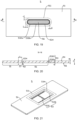
- FIG. 4 is a structural schematic view of the shell component 5 provided in some embodiments of the present disclosure
- FIG. 5 is a C-C sectional view of the shell component 5 shown in FIG. 4
- FIG. 6 is a partially enlarged view of the part E of the shell component 5 shown in FIG. 5
- FIG. 7 is a partial enlarged view of the shell component 5 provided in some other embodiments of the present disclosure.
- the embodiment of the present disclosure provides a shell component 5 for a battery cell 10, comprising a non-weak area 51 and a weak area 52 that are integrally formed, wherein the shell component 5 is provided with a groove part 53 by press forming, the non-weak area 51 is formed around the groove part 53, the weak area 52 is formed at the bottom of the groove part 53, and the weak area 52 is configured to be damaged when the internal pressure of the battery cell 10 is released, wherein the minimum thickness of the weak area 52 is A, and the minimum thickness of the non-weak area 51 is B, satisfying 0.05 ⁇ A/B ⁇ 0.95.
- the shell component 5 is a component that can accommodate electrode assembly 2 together with other components.
- the shell component 5 is a part of shell 1, which can be the end cover 11 of shell 1 as shell component 5, or the casing 12 of shell 1 as shell component 5.
- the shell component 5 can be made of metal materials, such as copper, iron, aluminum, steel, aluminum alloy, etc.
- the shell component 5 can be aluminum-plastic film.
- the weak area 52 is the weaker part of the shell component 5 compared to other areas.
- the weak area 52 of the shell component 5 can be destroyed to release the pressure inside the battery cell 10.
- weak area 52 can be destroyed through rupture, detachment, and other means.
- the weak area 52 can have various shapes, such as rectangular, circular, elliptical, annular, arc-shaped, U-shaped, H-shaped, etc.
- the thickness of weak area 52 can be uniform or uneven.
- the weak area 52 is formed at the bottom of the groove part 53, which can be formed by stamping to achieve the integral forming of the weak area 52 and the non-weak area 51. After stamping the groove part 53 onto the shell component 5, the area where the groove part 53 is set on the shell component 5 is thinned, thereby correspondingly forming a weak area 52.
- the groove part 53 can be a first stage groove, and along the depth direction of the groove part 53, the groove side of the groove part 53 is continuous.
- the groove part 53 is a groove with an internal space that is rectangular or cylindrical.
- the groove part 53 can also be a multi-stage groove, which is arranged along the depth direction of the groove part 53.
- the inner (deeper-position) first stage groove is set at the bottom surface of the outer (shallower-position) first stage groove.
- the groove part 53 is a stepped groove.
- multi-stage grooves can be stamped stage by stage along the depth direction of groove part 53, and the weak area 52 is formed at the bottom of the first stage groove located at the deepest position (innermost) in the multi-stage groove.
- the non-weak area 51 is formed around the groove part 53, and its strength is greater than that of the weak area 52.
- the weak area 52 is more susceptible to damage compared to the non-weak area 51.
- the non-weak area 51 can be the part of the shell component 5 that has not been stamped.
- the thickness of non-weak area 51 can be uniform or uneven.
- the thickness direction of weak area 52 is consistent with that of non-weak area 51, both in the Z direction.
- the minimum thickness of weak area 52 is the thickness at the thinnest position of weak area 52.
- the minimum thickness of non-weak area 51 is the thickness at the thinnest position of non-weak area 51.
- the shell component 5 has a first surface 54 and a second surface 55 relatively arranged, and the groove part 53 is recessed from the first surface 54 towards the direction close to the second surface 55.
- the part of the shell component 5 located between the bottom surface 531 of the groove part and the second surface 55 is a weak area 52.
- the bottom surface 531 of the groove part can be flat or curved. If the bottom surface 531 of the groove part is flat, the bottom surface 531 of the groove part can be parallel to the second surface 55 or set at a small angle. If the bottom surface 531 of the groove part is set at a small angle to the second surface 55, for example, if the angle between the two is within 10 degrees, the minimum distance between the bottom surface 531 of the groove part and the second surface 55 is the minimum thickness of the weak area 52. As shown in FIG. 6 , if the bottom surface 531 of the groove part is parallel to the second surface 55, the distance between the bottom surface 531 of the groove part and the second surface 55 is the minimum thickness of the weak area 52. As shown in FIG.
- the minimum distance between the bottom surface 531 of the groove part and the second surface 55 is the minimum thickness of the weak area 52.
- A/B can be a point value of any one of 0.05, 0.06, 0.07, 0.08, 0.1, 0.15, 0.2, 0.25, 0.3, 0.35, 0.4, 0.45, 0.5, 0.55, 0.6, 0.65, 0.7, 0.8, 0.85, 0.9, 0.95 or a range value between any two therein.
- the weak area 52 and the non-weak area 51 are formed integrally, and the reliability of the shell component 5 is higher.
- the groove part 53 is formed in the direction of press forming on the shell component 5, and A/B is controlled between 0.05 and 0.95, which can achieve the goal of refining the grain of the weak area 52, thereby improving the material mechanical properties of the weak area 52, enhancing the toughness and fatigue strength of the weak area 52, reducing the risk of damage to the weak area 52 during normal use of the battery cell 10, improving the service life of the battery cell 10, and reducing the risk of explosion of battery cells 10 in the event of thermal runaway.
- A/B can be a point value of any one of 0.12, 0.13, 0.14, 0.15, 0.17, 0.2, 0.22, 0.25, 0.27, 0.3, 0.32, 0.35, 0.37, 0.4, 0.42, 0.45, 0.47, 0.5, 0.52, 0.55, 0.57, 0.6, 0.62, 0.65, 0.66, 0.67, 0.7, 0.72, 0.75, 0.77, 0.8 or a range value between any two therein.
- the overall performance of external components is improved, ensuring that the weak areas 52 can be timely destroyed in the event of thermal runaway of the battery cell 10, and that the weak areas 52 have sufficient strength during the normal use of the battery cell 10.
- A/B can be a point value of any one of 0.2, 0.21, 0.22, 0.23, 0.24, 0.25, 0.26, 0.27, 0.28, 0.29, 0.3, 0.31, 0.32, 0.33, 0.34, 0.35, 0.36, 0.37, 0.38, 0.39, 0.4, 0.41, 0.42, 0.43, 0.44, 0.45, 0.46, 0.47, 0.48, 0.49, 0.5, or a range value between any two therein.
- A can be a point value of any one of 0.02mm, 0.03mm, 0.04mm, 0.05mm, 0.06mm, 0.1mm, 0.15mm, 0.2mm, 0.25mm, 0.3mm, 0.35 mm, 0.4 mm, 0.45 mm, 0.5 mm, 0.55 mm, 0.6 mm, 0.7 mm, 0.75 mm, 0.8 mm, 0.85 mm, 0.9 mm, 0.95 mm, 1 mm, 1.05 mm, 1.1 mm, 1.15 mm, 1.2 mm, 1.25 mm, 1.3 mm, 1.35 mm, 1.4 mm, 1.42mm, 1.43mm , 1.45 mm, 1.47mm, 1.5 mm, 1.55 mm, 1.6 mm, or a range value between any two therein.
- A can be a point value of any one of 0.06mm, 0.07mm, 0.08mm, 0.1mm, 0.15mm, 0.18mm, 0.2mm, 0.24mm, 0.25mm, 0.3mm, 0.35mm, 0.4mm, or a range value between any two therein.
- 1mm ⁇ B ⁇ 5mm.
- B can be a point value of any one of 1mm, 2mm, 3mm, 4mm, 5mm, or a range value between any two therein.
- the thickness of the non-weak area 51 is relatively large, the material used for the shell component 5 is more, and the weight of the shell component 5 is larger, which has poor economic effectiveness.
- B ⁇ 1mm the thickness of the non-weak area 51 is small, and the deformation resistance of the shell component 5 is poor.
- 1mm ⁇ B ⁇ 5mm makes the shell component 5 more economical and have better resistance to deformation.
- B can be a point value of any one of 1.2mm, 1.25mm, 1.3mm, 1.4mm, 1.5mm, 1.6mm, 1.7 mm, 1.8 mm, 1.9 mm, 2 mm, 2.1 mm, 2.2 mm, 2.3 mm, 2.4 mm, 2.5 mm, 2.6 mm, 2.7 mm, 2.8 mm, 2.9 mm, 3 mm, 3.1 mm, 3.2 mm, 3.3 mm, 3.4 mm, 3.5 mm, or a range value between any two therein.
- FIG. 8 is a grain view (schematic diagram ) of the shell component 5 shown in FIG. 5 .
- the average grain size of the weak area 52 is S 1
- the average grain size of the non-weak area 51 is S 2 , satisfying S 1 /S 2 ⁇ 0.9.
- the measurement method for average grain size can refer to the intercept method in GB 6394-2017 , which will not be elaborated here.
- measurements can be taken along the thickness direction of weak area 52.
- measurements can be taken along the thickness direction of non-weak area 51.
- S 1 /S 2 can be a point value of any one of 0.01, 0.03, 0.04, 0.05, 0.1, 0.15, 0.2, 0.25, 0.3, 0.35, 0.4, 0.45, 0.5, 0.55, 0.6, 0.65, 0.7, 0.75, 0.8, 0.85, 0.9, or a range value between any two therein.
- the average grain size of the weak area 52 differs significantly from that of the non-weak area 51. Reducing the average grain size of the weak area 52 can refine the grain of the weak area 52, improve the material mechanical properties of the weak area 52, and further enhance the toughness and fatigue strength of the weak area 52, which reduces the risk of weak area 52 being damaged under normal usage conditions of battery cell 10, and improves the service life of battery cell 10.
- S 1 /S 2 ⁇ 0.05.
- S 1 /S 2 can be a point value of any one of 0.1, 0.12, 0.15, 0.17, 0.2, 0.22, 0.25, 0.27, 0.3, 0.32, 0.35, 0.37, 0.4, 0.42, 0.45, 0.47, 0.5, or a range value between any two therein.
- 0.1 ⁇ m ⁇ S1 ⁇ 75 ⁇ m on the one hand, it reduces the difficulty of forming weak areas 52 and ensures the timely pressure relief of battery cells 10 in the event of thermal runaway; and on the other hand, it improves the toughness and fatigue resistance of the weak area 52, thereby reducing the risk of damage to the weak area 52 under normal usage conditions of the battery cell 10.
- S 1 can be a point value of any one of 1 ⁇ m, 1.5 ⁇ m, 1.6 ⁇ m, 2 ⁇ m, 2.5 ⁇ m, 2.6 ⁇ m, 3 ⁇ m, 3.3 ⁇ m, 3.5 ⁇ m, 3.6 ⁇ m, 4 ⁇ m, 4.5 ⁇ m, 4.6 ⁇ m, 5 ⁇ m, 5.5 ⁇ m, 5.6 ⁇ m, 6 ⁇ m, 6.5 ⁇ m, 6.6 ⁇ m, 6.7 ⁇ m, 7 ⁇ m, 7.5 ⁇ m, 7.6 ⁇ m, 8 ⁇ m, 8.5 ⁇ m, 8.6 ⁇ m, 9 ⁇ m, 9.5 ⁇ m, 9.6 ⁇ m, 10 ⁇ m, or a range value between any two therein.
- S 2 can be a point value of any one of 10 ⁇ m, 13 ⁇ m, 14 ⁇ m, 15 ⁇ m, 20 ⁇ m, 25 ⁇ m, 30 ⁇ m, 32 ⁇ m, 35 ⁇ m, 40 ⁇ m, 45 ⁇ m, 50 ⁇ m, 55 ⁇ m, 60 ⁇ m, 65 ⁇ m, 70 ⁇ m, 75 ⁇ m, 80 ⁇ m, 85 ⁇ m, 90 ⁇ m, 95 ⁇ m, 100 ⁇ m, 105 ⁇ m, 110 ⁇ m, 115 ⁇ m, 120 ⁇ m, 125 ⁇ m, 130 ⁇ m, 135 ⁇ m, 140 ⁇ m, 145 ⁇ m, 150 ⁇ m, or a range value between any two therein.
- S 2 can be a point value of any one of 30 ⁇ m, 32 ⁇ m, 35 ⁇ m, 37 ⁇ m, 40 ⁇ m, 42 ⁇ m, 45 ⁇ m, 47 ⁇ m, 50 ⁇ m, 52 ⁇ m, 55 ⁇ m, 57 ⁇ m, 60 ⁇ m, 62 ⁇ m, 65 ⁇ m, 67 ⁇ m, 70 ⁇ m, 72 ⁇ m, 75 ⁇ m, 77 ⁇ m, 80 ⁇ m, 82 ⁇ m, 85 ⁇ m, 87 ⁇ m, 90 ⁇ m, 92 ⁇ m, 95 ⁇ m, 97 ⁇ m, 100 ⁇ m, or a range value between any two therein.
- the average grain size of the weak area 52 is S 1 , satisfying 1 ⁇ A/S 1 ⁇ 100.
- A/S 1 can be a point value of any one of 1, 1.25, 1.5, 2, 3.125, 4, 4.8, 5, 7.5, 10, 15, 16, 20, 21, 22, 23, 24, 25, 30, 33, 34, 35, 37, 38, 40, 45, 48, 50, 55, 56, 60, 64, 65, 70, 75, 76, 78, 80, 85, 90, 93, 94, 95, 100, or a range value between any two therein.
- A/S 1 ⁇ 1 in the thickness direction of the weak area 52, the number of grain layers in the weak area 52 is less, and the fatigue strength of the weak area 52 is too small; and if A/S 1 >100, in the thickness direction of the weak area 52, there are too many grain layers in the weak area 52, and the strength of the weak area 52 is too large, which is prone to the risk of the weak area 52 not being damaged in time when the battery cell 10 undergoes thermal runaway.
- 1 ⁇ A/S 1 ⁇ 100 increases the number of grain layers in the thickness direction of the weak area 52, improves the fatigue strength of the weak area 52, and reduces the risk of damage to the weak area 52 under normal usage conditions of the battery cell 10; and on the other hand, enables the weak areas 52 to be more timely destroyed in the event of thermal runaway of battery cells 10, in order to achieve the goal of timely pressure relief.
- A/S 1 can be a point value of any one of 5, 5.5, 6, 6.5, 7, 7.5, 8, 8.4, 8.5, 8.8, 8.9, 9, 9.5, 9.6, 10, 10.5, 11, 11.4, 11.5, 12, 12.5, 13, 13.5, 14, 14.5, 15, 15.5, 16, 16.5, 17, 17.5, 18, 18.5, 19, 19.5, 20, or a range value between any two therein.
- the overall performance of shell component 5 is improved, ensuring that the weak areas 52 can be timely destroyed in the event of thermal runaway of the battery cell 10, and that the weak areas 52 have sufficient fatigue strength during the normal use conditions of the battery cell 10, so as to improve the service life of the battery cell 10.
- the hardness of the weak area 52 is H 1 , satisfying 5HBW/mm ⁇ H 1 /A ⁇ 10000 HBW/mm.
- H 1 /A can be a point value of any one of 5HBW/mm, 6HBW/mm, 7HBW/mm, 20HBW/mm, 31HBW/mm, 32HBW/mm, 37.5HBW/mm, 42HBW/mm, 43HBW/mm, 50HBW/mm, 60HBW/mm, 61HBW/mm, 62HBW/mm, 63HBW/mm, 64HBW/mm, 75HBW/mm, 90HBW/mm, 100HBW/mm, 120 HBW/mm, 150HBW/mm, 190HBW/mm, 500HBW/mm, 1000HBW/mm, 1200HBW/mm, 1750HBW/mm, 1800HBW/mm, 2100 HBW/mm, 4000HBW/mm, 5000 HBW/mm, 8000HBW/mm, 9000 HBW/mm and 10000HBW/mm, or a range value between any two therein.
- the hardness of weak area 52 is Brinell hardness, measured in HBW.
- the measurement method of Brinell hardness can be implemented according to the measurement principle in GBIT 23.1-2018.
- the hardness of weak area 52 can be measured on the inner or outer surface in the thickness direction of weak area 52. Taking the shell component 5 being end cover 11 of the battery cell 10 as an example, the hardness of the weak area 52 can be measured on the outer surface of the weak area 52 facing away from the interior of the battery cell 10, or on the inner surface of the weak area 52 facing towards the interior of the battery cell 10.
- the weak area 52 When H 1 /A>10000HBW/mm, the weak area 52 is relatively thin and has a high hardness, which can cause the weak area 52 to be very thin and brittle. The weak area 52 is easily damaged under the normal use conditions of battery cell 10, and the service life of battery cell 10 is relatively short. When H 1 /A ⁇ 5HBW/mm, the weak area 52 is thicker and has lower hardness. When the thermal runaway of battery cell 10 occurs, the weak area 52 will be stretched and extended, resulting in poor pressure relief timeliness.
- 5HBW/mm ⁇ H 1 /A ⁇ 10000 HBW/mm can make the weak area 52 have sufficient strength under normal use conditions of the battery cell 10, and the weak area 52 not easily damaged by fatigue, thereby improving the service life of the battery cell 10; and can also enable the shell component 5 to release pressure in a timely manner through weak areas 52 when the battery cell 10 loses thermal control, thereby reducing the explosion risk of battery cell 10 and improving the safety of the battery cell 10.
- 190HBW/mm ⁇ H 1 /A ⁇ 4000 HBW/mm In some embodiments, 190HBW/mm ⁇ H 1 /A ⁇ 4000 HBW/mm.
- H 1 /A can be a point value of any one of 190HBW/mm, 250HBW/mm, 280 HBW/mm, 300HBW/mm, 350HBW/mm, 400HBW/mm, 450HBW/mm, 500HBW/mm, 600HBW/mm, 700HBW/mm, 875HBW/mm, 1000HBW/mm, 1200HBW/mm, 1500HBW/mm, 1750HBW/mm, 1800HBW/mm, 2000HBW/mm, 2100 HBW/mm, 2500HBW/mm, 3000HBW/mm, 3500HBW/mm, 4000HBW/mm, or a range value between any two therein.
- the overall performance of shell component 5 is improved, ensuring that the weak areas 52 can be timely destroyed in the event of thermal runaway of the battery cell 10, and that the weak areas 52 have sufficient strength during the normal use conditions of the battery cell 10.
- the service life of battery cells 10 is improved.
- the hardness of the weak area 52 is H 1
- the hardness of the non-weak area 51 is H 2 , satisfying H 1 >H 2 .
- the hardness of non-weak area 51 is Brinell hardness, measured in HBW. In the actual measurement process, the hardness of non-weak area 51 can be measured on the inner or outer surface in the thickness direction of non-weak area 51. Taking the shell component 5 being end cover 11 of the battery cell 10 as an example, the hardness of the non-weak area 51 can be measured on the outer surface of the non-weak area 51 facing away from the interior of the battery cell 10, or on the inner surface of the non-weak area 51 facing towards the interior of the battery cell 10.
- H 1 >H 2 , it is equivalent to increasing the hardness of the weak area 52, thereby enhancing its strength and reducing the risk of damage to the weak area 52 under normal usage conditions of the battery cell 10.
- H 1 /H 2 ⁇ 5.
- H 1 /H 2 can be a point value of any one of 1.1, 1.5, 2, 2.5, 3, 3.5, 3.6, 4, 4.5, or 5, or a range value between any two therein.
- H 1 /H 2 >5 it may cause the hardness of weak area 52 to be too large, and it may be difficult for weak area 52 to be damaged during thermal runaway of battery cell 10.
- H 1 /H 2 ⁇ 5 reduces the risk of weak areas 52 being unable to be damaged in a timely manner during thermal runaway of battery cells 10, and improves the safety of battery cells 10.
- H 1 /H 2 If H 1 /H 2 is too large, it may be difficult to damage the weak area 52 during the thermal runaway of the battery cell 10. Therefore, H 1 /H 2 ⁇ 5 reduces the risk of weak areas 52 being unable to be damaged in a timely manner during thermal runaway of battery cells 10, and improves the safety of battery cells 10.
- H 1 /H 2 ⁇ 2.5.
- H 1 /H 2 can be a point value of any one of 1.1, 1.11, 1.12, 1.2, 1.25, 1.3, 1.4, 1.5, 1.6, 1.7, 1.71, 1.72, 1.8, 1.9, 2, 2.1, 2.2, 2.3, 2.4, 2.5, or a range value between any two therein.
- H 1 /H 2 ⁇ 2.5 this can further reduce the risk of weak areas 52 being unable to be damaged in a timely manner during thermal runaway of battery cells 10.
- H 2 can be a point value of any one of 5HBW, 8HBW, 9 HBW, 9.5 HBW, 10HBW, 12HBW, 13HBW, 15HBW, 16 HBW, 19HBW, 20HBW, 30HBW, 40 HBW, 50HBW, 52HBW, 52.5HBW, 53HBW, 60 HBW, 70HBW, 80HBW, 90HBW, 100HBW, 110HBW, 120HBW, 130HBW, 140HBW, 150HBW, or a range value between any two therein.
- H 1 can be a point value of any one of 5HBW, 6 HBW, 8HBW, 10HBW, 15HBW, 19HBW, 20HBW, 22.8HBW, 30HBW, 32HBW, 40HBW, 50HBW, 60 HBW, 70HBW, 80HBW, 90HBW, 100HBW, 110HBW, 120HBW, 130HBW, 140HBW, 150HBW, 160HBW, 170HBW, 180HBW, 190HBW, 200HBW, or a range value between any two therein.
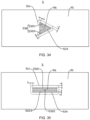
- FIG. 9 is a structural schematic view (showing the first stage notching groove 532) of the shell component 5 provided in some other embodiments of the present disclosure
- FIG. 10 is a E-E sectional view of the shell component 5 shown in FIG. 9
- FIG. 11 is a structural schematic view (showing the first stage notching groove 532) of the shell component 5 provided in some other embodiments of the present disclosure
- FIG. 12 is a F-F sectional view of the shell component 5 shown in FIG. 11
- FIG. 13 is a structural schematic view (showing the first stage notching groove 532) of the shell component 5 provided in some other embodiments of the present disclosure
- FIG. 10 is a E-E sectional view of the shell component 5 shown in FIG. 9
- FIG. 11 is a structural schematic view (showing the first stage notching groove 532) of the shell component 5 provided in some other embodiments of the present disclosure
- FIG. 12 is a F-F sectional view of the shell component 5 shown in FIG. 11
- FIG. 13 is a structural schematic view (
- the shell component 5 has a pressure relief area 56, wherein the groove part 53 includes a first stage notching groove 532, the notching groove 532 is set along the edge of the pressure relief area 56, the pressure relief area 56 is configured to open with the notching groove 532 as the boundary, and the weak area 52 forms the bottom of the notching groove 532.
- the pressure relief area 56 is the area where shell component 5 can open after weak area 52 is damaged. For example, when the internal pressure of battery cell 10 reaches the threshold, the weak area 52 cracks, and the pressure relief area 56 opens outward under the action of the discharge inside battery cell 10. During this process, the weak area 52 cracks along the notching groove 532, and the pressure relief area 56 opens, thereby achieving the opening of the pressure relief area 56 with the notching groove 532 as the boundary. After the pressure relief area 56 is opened, the shell component 5 can form a discharge port at the position corresponding to the pressure relief area 56. The discharge inside the battery cell 10 can be discharged through the discharge port to release the pressure inside the battery cell 10.
- the notching groove 532 can be formed on the shell component 5 by stamping.
- the notching groove 532 in groove part 53 is only a first stage groove, which can be formed by a single stamping.
- the notching groove 532 can be of various shapes, such as annular groove, arc-shaped groove, U-shaped groove, H-shaped groove, etc.
- the weak area 52 is formed at the bottom of the notching groove 532, and its shape is the same as that of the notching groove 532.
- the weak area 52 is a U-shaped groove, which extends along the U-shaped trajectory.
- the maximum width of notching groove 532 is X, wherein X ⁇ 10mm.
- the width of the widest position of notching groove 532 is the maximum width of notching groove 532.
- the weak area 52 forms the bottom of the notching groove 532.
- the pressure relief area 56 can be opened with the weak area 52 as the boundary to achieve pressure relief, increasing the pressure relief area of the shell component 5.
- the shell component 5 has a first surface 54 and a second surface 55 relatively arranged, and the notching groove 532 is recessed from the first surface 54 towards the direction close to the second surface 55.
- the first surface 54 can be the inner surface of the shell component 5 facing the interior of the battery cell 10
- the second surface 55 can be the outer surface of the shell component 5 facing away from the interior of the battery cell 10. It can also be that the first surface 54 is the outer surface of the shell component 5 facing away from the interior of the battery cell 10
- the second surface 55 is the inner surface of the shell component 5 facing towards the interior of the battery cell 10.
- the first surface 54 is parallel to the second surface 55, and the minimum thickness of the non-weak area 51 is the distance between the first surface 54 and the second surface 55.
- the bottom surface of notching groove 532 is the bottom surface 531 of groove part.
- the part of shell component 5 between the bottom surface of notching groove 532 and the second surface 55 is the bottom wall of notching groove 532, which is the weak area 52.
- the groove part 53 only includes a first stage notching groove 532, which is the groove part 53.
- the groove part 53 is the first stage groove, with a simple structure.
- the notching groove 532 can be formed on the first surface 54 for easy molding, improving production efficiency and reducing production costs.
- FIG. 15 is a structural schematic view (showing two levels of notching grooves 532) of the shell component 5 provided in some other embodiments of the present disclosure
- FIG. 16 is a K-K sectional view of the shell component 5 shown in FIG. 15
- FIG. 17 is a structural schematic view (showing two levels of notching grooves 532) of the shell component 5 provided in some other embodiments of the present disclosure
- FIG. 18 is a M-M sectional view of the shell component 5 shown in FIG. 17
- FIG. 19 is a structural schematic view (showing two levels of notching grooves 532) of the shell component 5 provided in some other embodiments of the present disclosure
- FIG. 15 is a structural schematic view (showing two levels of notching grooves 532) of the shell component 5 provided in some other embodiments of the present disclosure
- FIG. 16 is a K-K sectional view of the shell component 5 shown in FIG. 15
- FIG. 17 is a structural schematic view (showing two levels of notching grooves 532) of the shell component 5 provided in some other
- the shell component 5 includes a first surface 54 and a second surface 55 that are relatively arranged, and the groove part 53 includes multi-stage notching grooves 532, wherein the multi-stage notching grooves 532 are sequentially arranged along the direction from the first surface 54 to the second surface 55 on the shell component 5; and the weak area 52 is formed at the bottom of the first stage notching groove 532, which is farthest from the first surface 54.
- the shell component 5 has a pressure relief area 56, and each stage of the notching groove 532 is set along the edge of the pressure relief area 56.
- the pressure relief area 56 is configured to open with the first stage notching groove 532 farthest from the first surface 54 as the boundary.
- the groove part 53 includes a multi-stage notching groove 532, and it can be understood that the groove part 53 is a multi-stage groove.
- Each stage of notching groove 532 is set along the edge of the pressure relief area 56. It can be understood that each stage of notching groove 532 is set around the pressure relief area 56, so that the extension directions of the multi-stage notching grooves 532 are basically the same, and the shapes of the multi-stage notching grooves 532 are basically the same.
- the notching groove 532 in groove part 53 can be of two, three, four, or more stages. Each stage of notching groove 532 can be formed on the shell component 5 by stamping.
- various stages of notching grooves 532 can be formed by sequentially stamping along the direction from the first surface 54 to the second surface 55.
- stamping to form a multi-stage notching groove 532 multiple stamping can be used to form a corresponding multi-stage notching groove 532, with each stamping forming one stage of notching groove 532.
- the notching groove 532 can be of various shapes, such as annular groove, arc-shaped groove, U-shaped groove, H-shaped groove, etc.
- the pressure relief area 56 is the area where shell component 5 can open after weak area 52 is damaged.
- the first stage notching groove 532 farthest from the first surface 54 is located at the edge of the pressure relief area 56.
- the weak area 52 cracks along the first stage notching groove 532 farthest from the first surface 54, thereby achieving the opening of the pressure relief area 56 with the first stage notching groove 532 farthest from the first surface 54 as the boundary.
- the weak area 52 is formed at the bottom of the first stage notching groove 532 farthest from the first surface 54, and the first stage notching groove 532 farthest from the first surface 54 is the first stage notching groove 532 at the deepest position (innermost).
- the first stage notching groove 532 far from the first surface 54 is set on the bottom surface of the first stage notching groove 532 near the first surface 54.
- the part of shell component 5 between the bottom surface of the first stage notching groove 532 farthest from the first surface 54 and the second surface 55 is the bottom wall of the first stage notching groove 532 farthest from the first surface 54, which is the weak area 52.
- the bottom surface of the first stage notching groove 532 which is farthest from the first surface 54, is the bottom surface 531 of the groove part.
- the first stage notching groove 532 farthest from the first surface 54 is the innermost first stage notching groove 532b, and the first stage notching groove 532 closest to the first surface 54 is the outermost first stage notching groove 532a.
- the maximum width of the outermost first stage notching groove 532a is X, with X ⁇ 10mm.
- the width of the widest position of the outermost first stage notching groove 532a is the maximum width of the outermost first stage notching groove 532a.
- multi-stage notching grooves 532 can be formed on the shell component 5 stage by stage, which can reduce the molding depth of each stage of notching groove 532, thereby reducing the molding force on the shell component 5 when forming each stage of notching groove 532, and reducing the risk of cracking on the shell component 5.
- the shell component 5 is less likely to fail due to generating cracking at the location of the notching groove 532, thereby improving the service life of the shell component 5.
- the first stage notching groove 532 farthest from the second surface 55 is recessed from the first surface 54 towards the direction close to the second surface 55.
- the two stages of notching grooves 532 are the first stage notching groove and the second stage notching groove, respectively.
- the first stage notching groove is set on the first surface 54, that is, the first stage notching groove is concave from the first surface 54 towards the direction close to the second surface 55
- the second stage notching groove is set on the bottom surface of the first stage notching groove.
- the second stage notching groove is concave from the bottom surface of the first stage notching groove towards the direction close to the second surface 55.
- the first stage notching groove is the outermost first stage notching groove 532a
- the second stage notching groove is the innermost first stage notching groove 532b.
- the groove part 53 is composed of multi-stage notching grooves 532.
- multi-stage notching grooves 532 can be gradually machined in the direction from the first surface 54 to the second surface 55, resulting in higher forming efficiency.
- FIG. 21 is an axonometric drawing of the shell component 5 provided in some embodiments of the present disclosure
- FIG. 22 is a structural schematic view (showing the first stage notching groove 532 and the first stage sink groove 533) of the shell component 5 shown in FIG. 21
- FIG. 23 is a O-O sectional view of the shell component 5 shown in FIG. 22
- FIG. 24 is a structural schematic view (showing the first stage notching groove 532 and the first stage sink groove 533) of the shell component 5 provided in some other embodiments of the present disclosure
- FIG. 25 is a P-P sectional view of the shell component 5 shown in FIG. 24 ;
- FIG. 26 is a structural schematic view (showing the first stage notching groove 532 and the first stage sink groove 533) of the shell component 5 provided in some other embodiments of the present disclosure; and FIG. 27 is a Q-Q sectional view of the shell component 5 shown in FIG. 26 .
- the shell component 5 includes a first surface 54 and a second surface 55 that are relatively arranged, and the groove part 53 also includes a first stage sink groove 533, wherein the sink groove 533 is recessed from the first surface 54 towards the direction close to the second surface 55, and the pressure relief area 56 is formed on the bottom wall 5331 of the sink groove.
- the groove part 53 can include a first stage sink groove 533. Understandably, there are both notching groove 532 and sink groove 533 in groove part 53, and the groove part 53 is a multi-stage groove.
- the sink groove 533 and the notching groove 532 are set along the direction from the first surface 54 to the second surface 55.
- a sink groove 533 can be formed on the shell component 5 first, and then a notching groove 532 can be formed on the bottom wall 5331 of the sink groove.
- the sink groove 533 can be formed on the shell component 5 by stamping.
- the bottom wall 5331 of the sink groove is the part of the shell component 5 located below the bottom surface of the sink groove 533.
- the remaining part of the shell component 5 in the area where the sink groove 533 is set is the bottom wall 5331 of the sink groove.
- the portion of the shell component 5 located between the bottom surface of the sink groove 533 and the second surface 55 is the bottom wall 5331 of the sink groove.
- the pressure relief area 56 can be a part of the bottom wall 5331 of the sink groove.
- the setting of the sink groove 533 can reduce the depth of the notching groove 532 while ensuring a certain thickness of the final weak area 52, thereby reducing the forming force on the shell component 5 during the formation of the notching groove 532 and reducing the risk of generating cracking on the shell component 5.
- the sink groove 533 can provide avoidance space for the pressure relief area 56 during the opening process. Even if the first surface 54 is obstructed by obstacles, the pressure relief area 56 can still be opened to release the pressure.
- FIG. 28 is a structural schematic view (showing the first stage notching groove 532 and two levels of sink grooves 533) of the shell component 5 provided in some embodiments of the present disclosure
- FIG. 29 is a R-R sectional view of the shell component 5 shown in FIG. 28
- FIG. 30 is a structural schematic view (showing the first stage notching groove 532 and two levels of sink grooves 533) of the shell component 5 provided in some other embodiments of the present disclosure
- FIG. 31 is a S-S sectional view of the shell component 5 shown in FIG. 30 ;
- FIG. 32 is a structural schematic view (showing the first stage notching groove 532 and two levels of sink grooves 533) of the shell component 5 provided in some other embodiments of the present disclosure; and FIG. 33 is a T-T sectional view of the shell component 5 shown in FIG. 32 .
- the shell component 5 includes a first surface 54 and a second surface 55 that are relatively arranged, and the groove part 53 also includes multi-stage sink grooves 533, wherein the multi-stage sink grooves 533 are sequentially arranged along the direction from the first surface 54 to the second surface 55 on the shell component 5; the first stage sink groove 533 farthest from the second surface 55 is concave from the first surface 54 towards the second surface 55; and the pressure relief area 56 is formed on the bottom wall 5331 of the first stage sink groove farthest from the first surface 54.
- the groove part 53 can include a multi-stage sink groove 533. Understandably, there are both notching groove 532 and sink groove 533 in groove part 53, and the groove part 53 is a multi-stage groove.
- the sink groove 533 and the notching groove 532 are set along the direction from the first surface 54 to the second surface 55.
- multi-stage sink grooves 533 can be formed on the shell component 5 first, and then a notching groove 532 can be formed on the bottom wall 5331 of the first stage sink groove furthest from the first surface 54.
- the first stage sink groove 533 which is farthest from the second surface 55 (closest to the first surface 54), is the outermost first stage sink groove 533a, and the first stage sink groove 533, which is farthest from the first surface 54, is the innermost first stage sink groove 533b.
- the outermost first stage sink groove 533a is set on the first surface 54, and the outermost first stage sink groove 533a is concave from the first surface 54 towards the second surface 55.
- the groove bottom wall 5331 of the first stage sink groove farthest from the first surface 54 is the part of the shell component 5 located below the groove bottom surface of the first stage sink groove 533 farthest from the first surface 54.
- the residual part of the shell component 5 in the area where the first stage sink groove 533 farthest from the first surface 54 is set is the groove bottom wall 5331 of the sink groove.
- the portion of the shell component 5 located between the bottom surface of the first stage sink groove 533 farthest from the first surface 54 and the second surface 55 is the bottom wall 5331 of the first stage sink groove farthest from the first surface 54.
- the pressure relief area 56 can be a part of the bottom wall 5331 of the first stage sink groove farthest from the first surface 54.
- the sink groove 533 in groove part 53 can be of two, three, four, or more stages.
- the first stage sink groove 533 far from the first surface 54 is set on the bottom surface of the first stage sink groove 533 near the first surface 54.
- the contour of the bottom surface of the multi-stage sink groove 533 decreases stage by stage.
- Each stage of sink groove 533 can be formed on the shell component 5 by stamping. During the molding process, various stages of sink grooves 533 can be sequentially stamped along the direction from the first surface 54 to the second surface 55, and then the notching groove 532 is stamped.
- the sink grooves 533 in the groove part 53 are of two stages and the notching groove 532 is of a single stage
- two stamping processes can be carried out first to form a two-stage sink groove 533 correspondingly, and then another stamping process can be carried out to form a first stage notching groove 532 correspondingly.
- the sink groove 533 in the groove part 53 is in a two-stage structure.
- the forming depth of each stage of sink groove 533 can be reduced, which can reduce the forming force on the shell component 5 during the forming of each stage of sink groove 533, and reduce the risk of generating cracking on the shell components 5.
- the multi-stage sink grooves 533 can provide avoidance space for the pressure relief area 56 during the opening process. Even if the first surface 54 is obstructed by obstacles, the pressure relief area 56 can still be opened to release the pressure.
- the internal space of the sink groove 533 is of a cylinder, prismoid, circular truncated cone, or frustum.
- the internal space of sink groove 533 is limited by the side and bottom surfaces of the sink groove 533.
- the prismoid can be triangular prism , quadrangular prism, pentagonal prism, hexagonal prisms, etc.
- the frustum can be a triangular frustum, a quadrangular frustum, a pentagonal frustum, a hexagonal frustum, etc.
- the internal space of groove part 53 is of a quadrangular prism, and specifically, the internal space of groove part 53 is of a cuboid.
- the sink groove 533 has a simple structure, is easy to form, and can provide more avoidance space for the pressure relief area 56 during the opening process.
- FIG. 34 is a structural schematic view (showing the first stage notching groove 532 in V shape) of the shell component 5 provided in some embodiments of the present disclosure.
- the notching groove 532 includes a first groove segment 5321 and a second groove segment 5322.
- the first groove segment 5321 intersects with the second groove segment 5322, and the first groove segment 5321 and the second groove segment 5322 are set along the edge of the pressure relief area 56.
- the first groove segment 5321 and the second groove segment 5322 can be linear grooves or non-linear grooves, such as arc-shaped grooves. In the embodiment where the first groove segment 5321 and the second groove segment 5322 are both linear grooves, it can be understood that the first groove segment 5321 and the second groove segment 5322 both extend along the straight line, and the first groove segment 5321 and the second groove segment 5322 can be set at acute, right or obtuse angles.
- the first groove segment 5321 and the second groove segment 5322 can be set in a cross manner, for example, the intersection position of the first groove segment 5321 and the second groove segment 5322 is located at the midpoint positions of the first groove segment 5321 and the second groove segment 5322. As shown in FIG.
- the intersection position of the first groove segment 5321 and the second groove segment 5322 can also be located at one end of the first groove segment 5321 and one end of the second groove segment 5322.
- the first groove segment 5321 and the second groove segment 5322 form a V-shaped structure, and the notching groove 532 is V-shaped.
- the stress at the intersection position of the first groove segment 5321 and second groove segment 5322 is more concentrated, allowing the weak area 52 to be the first to be damaged at the intersection position of the first groove segment 5321 and second groove segment 5322.
- the weak area 52 can be made thicker to reduce the forming depth of the notching groove 532.
- the notching groove 532 further can include a third groove segment 5323, wherein the first groove segment 5321 and the third groove segment 5323 are set opposite to each other, the second groove segment 5322 and the third groove segment 5323 intersect, and the first groove segment 5321, the second groove segment 5322, and the third groove segment 5323 are set along the edge of the pressure relief area 56.
- the first groove segment 5321, the second groove segment 5322, and the third groove segment 5323 can all be linear grooves or non-linear grooves, such as arc-shaped grooves. In the embodiments where the first groove segment 5321, the second groove segment 5322, and the third groove segment 5323 are all linear grooves, it can be understood that the first groove segment 5321, the second groove segment 5322, and the third groove segment 5323 all extend along the straight line.
- the first groove segment 5321 and the third groove segment 5323 can be set in parallel or at an angle.
- the first groove segment 5321 and the third groove segment 5323 can be perpendicular to the second groove segment 5322, or they may be not perpendicular to the second groove segment 5322.
- connection position between the second groove segment 5322 and the first groove segment 5321 can be located at one end of the first groove segment 5321, or at a position deviating from the end of the first groove segment 5321.
- the connection position between the second groove segment 5322 and the first groove segment 5321 is located at the midpoint position of the first groove segment 5321 in the extension direction.
- the connection position between the second groove segment 5322 and the third groove segment 5323 can be located at one end of the third groove segment 5323, or at a position deviating from the end of the third groove segment 5323.
- the connection position between the second groove segment 5322 and the third groove segment 5323 is located at the midpoint position of the extension direction of the third groove segment 5323.
- the groove part 53 includes a multi-stage notching groove 532
- the first groove segment 5321 of the first stage notching groove 532 far from the first surface 54 is set on the bottom surface of the first groove segment 5321 of the first stage notching groove 532 near the first surface 54.
- the second groove segment 5322 of the first stage notching groove 532 far away from the first surface 54 is located on the bottom surface of the second groove segment 5322 of the first stage notching groove 532 near the first surface 54.
- the third groove segment 5323 of the first stage notching groove 532 far away from the first surface 54 is located on the bottom surface of the third groove segment 5323 of the first stage notching groove 532 near the first surface 54.
- the pressure relief area 56 can be opened with the first groove segment 5321, second groove segment 5322, and third groove segment 5323 as boundaries.
- the pressure relief area 56 is easier to open, achieving large-scale pressure relief of the shell component 5.
- the first groove segment 5321, the second groove segment 5322, and the third groove segment 5323 define two pressure relief areas 56, which are located on both sides of the second groove segment 5322.
- first groove segment 5321, the second groove segment 5322, and the third groove segment 5323 form an H-shaped notching groove 532.
- the connection position between the second groove segment 5322 and the first groove segment 5321 is located at the midpoint position of the first groove segment 5321, and the connection position between the third groove segment 5323 and the second groove segment 5322 is located at the midpoint position of the third groove segment 5323.
- Two pressure relief areas 56 are symmetrically arranged on both sides of the second groove segment 5322.
- Two pressure relief areas 56 are located on both sides of the second groove segment 5322, so that the two pressure relief areas 56 are separated by the second groove segment 5322. After the shell component 5 ruptures at the position of the second groove segment 5322, the two pressure relief areas 56 can be opened in an opposite manner along the first groove segment 5321 and the third groove segment 5323 to achieve pressure relief, which can effectively improve the pressure relief efficiency of the shell component 5.
- first groove segment 5321, the second groove segment 5322, and the third groove segment 5323 are sequentially connected, with the first groove segment 5321, the second groove segment 5322, and the third groove segment 5323 defining a pressure relief area 56.
- the first groove segment 5321, the second groove segment 5322, and the third groove segment 5323 are sequentially connected to form a U-shaped notching groove 532.
- the notching groove 532 is a groove that extends along a non-closed trajectory.
- Non-closed trajectories refer to trajectories that are not connected at both ends in the direction of extension.
- Non-closed trajectories can be curved trajectories, U-shaped trajectories, etc.
- the notching groove 532 is a groove along a non-closed trajectory, and the pressure relief area 56 can be opened by flipping. After opening, the pressure relief area 56 is ultimately connected to other areas of the shell component 5, reducing the risk of splashing after opening the pressure relief area 56.
- the notching groove 532 is an arc-shaped groove.
- the arc-shaped groove is a groove that extends along an arc-shaped trajectory, and the arc-shaped trajectory is a non-closed trajectory.
- the center angle of the arc-shaped groove can be less than, equal to, or greater than 180°.
- the arc-shaped groove is simple in structure and easy to form. During the pressure relief process, the pressure relief area 56 can quickly rupture along the arc-shaped groove, allowing the pressure relief area 56 to open quickly.
- the notching groove 532 is a groove that extends along a closed trajectory.
- Closed trajectories refer to trajectories that are connected at both ends, and can be circular trajectories, rectangular trajectories, etc.
- the shell component 5 can rupture along the notching groove 532, allowing the pressure relief area 56 to open in a detached manner, increasing the pressure relief area of the shell component 5 and improving the pressure relief rate of the shell component 5.
- the notching groove 532 is an annular groove.
- the annular grooves can be rectangular or circular.
- the annular groove has a simple structure and is easy to form. During the pressure relief process, the shell component 5 can quickly rupture along the annular groove to quickly open the pressure relief area 56.
- the area of the pressure relief area 56 is D, which satisfies: 90mm 2 ⁇ D ⁇ 1500mm 2 .
- the shaded area is the area of the pressure relief area 56.
- the area of the pressure relief area 56 is the area of the region limited by the first stage notching groove 532 at the deepest position (innermost).
- D can be a point value of any one of 90 mm 2 , 95 mm 2 , 100 mm 2 , 150 mm 2 , 200 mm 2 , 250 mm 2 , 300 mm 2 , 350 mm 2, 400 mm 2 , 450 mm 2 , 500 mm 2 , 550 mm 2, 600 mm 2 , 650 mm 2 , 700 mm 2 , 750 mm 2 , 800 mm 2 , 900 mm 2 , 950 mm 2 , 1000 mm 2 , 1050 mm 2 , 1100 mm 2 , 1150 mm 2 , 1200 mm 2 , 1250 mm 2 , 1300 mm 2 , 1350 mm 2 , 1400 mm 2 , 1450 mm 2 , 1500 mm 2 , or a range value between any two therein.
- 150mm 2 ⁇ D ⁇ 1200mm 2 This makes the comprehensive performance of shell component 5 better, while making shell component 5 have a larger pressure relief area and good impact resistance.
- 200mm 2 ⁇ D ⁇ 1000mm 2 Further, 200mm 2 ⁇ D ⁇ 1000mm 2 .
- the shell component 5 has a first surface 54 and a second surface 55 oppositely arranged, the groove part 53 is concave from the first surface 54 towards the direction close to the second surface 55, the groove part 53 forms an outer edge 534 on the first surface 54, and the area beyond the preset distance from the outer edge 534 of the shell component 5 is the non-weak area 51.
- the preset distance is L.
- L can be 1mm, 2mm, 3mm, 4mm, 5mm, 6mm, 7mm, 8mm, 9mm, 10mm, etc.
- the groove part 53 only includes a first stage notching groove 532, which is set on the first surface 54.
- the groove side of the notching groove 532 intersects with the first surface 54 to form an outer edge 534, and the groove side of the notching groove 532 surrounds the groove bottom surface of the notching groove 532.
- the groove side of the notching groove 532 intersects with the first surface 54 to form an inner ring line and an outer ring line located outside the inner ring line, with the outer ring line being the outer edge 534.
- the groove part 53 only includes a multi-stage notching groove 532.
- the outermost first stage notching groove 532a is set on the first surface 54, and the groove side of the outermost first stage notching groove 532a intersects with the first surface 54 to form an outer edge 534.
- the outermost first stage notching groove 532a intersects with the first surface 54 to form an inner ring line and an outer ring line located outside the inner ring line, with the outer ring line being the outer edge 534.
- the groove part 53 further includes a first stage sink groove 533, which is set on the first surface 54.
- the groove side of the sink groove 533 intersects with the first surface 54 to form an outer edge 534, and the groove side of the sink groove 533 surrounds the groove bottom surface of the sink groove 533.
- the groove part 53 further includes a multi-stage sink groove 533, the outermost first stage sink groove 533a is set at the first surface 54, and the groove side of the outermost first stage sink groove 533a intersects with the first surface 54 to form an outer edge 534.
- the distance between the outer edge 534 and the inner edge 511 of the non-weak area 51 is the preset distance L.
- the shape of the inner edge 511 of the non-weak area 51 can be basically the same as the shape of the outer edge 534.
- the direction of the preset distance L can be perpendicular to the thickness direction of the non-weak area 51, which means that the preset distance L can be measured along a direction perpendicular to the thickness direction of the non-weak area 51.
- the non-weak area 51 is at a certain distance from the groove part 53, and is not easily affected by the forming process of the groove part 53, making the grains in the non-weak area 51 more uniform.
- L 5mm.
- FIG. 35 is a structural schematic view of the shell component 5 provided in some other embodiments of the present disclosure.
- the inner edge 511 of the non-weak area 51 is not located in the pressure relief area 56, and the inner edge 511 of the non-weak area 51 is roughly rectangular.
- the distance between the first groove segment 5321 and the inner edge 511 of the non-weak area 51 is L.
- the distance between the first groove segment 5321 and the inner edge 511 of the non-weak area 51 is L.
- the distance between the first groove segment 5321 and the inner edge 511 of the non-weak area 51 is L.
- the distance between the third groove segment 5323 and the inner edge 511 of the non-weak area 51 is L.
- the distance between the third groove segment 5323 and the inner edge 511 of the non-weak area 51 is L.
- FIG. 36 is a grain view (schematic diagram) of the shell component 5 provided in some other embodiments of the present disclosure.
- the shell component 5 also includes a transition area 57, which connects the weak area 52 and the non-weak area 51, wherein the average grain size of the transition area 57 is S 3 , satisfying S 3 ⁇ S 2 .
- S 3 >S 1 .
- the transition area 57 is the part of the shell component 5 that connects the weak area 52 and the non-weak area 51.
- the transition area 57 surrounds the outer side of the weak area 52, and the non-weak area 51 surrounds the outer side of the transition area 57.
- the weak area 52, transition area 57, and non-weak area 51 are formed integrally.
- the average grain size of transition area 57 can gradually decrease from non-weak area 51 to weak area 52.
- the average grain size of the transition area 57 located in the outer area of the sink groove 533 can be greater than the average grain size of the transition area 57 located in the bottom area of the sink groove 533, and the average grain size of the transition area 57 located in the outer area of the sink groove 533 can be less than or equal to the average grain size S 2 of the non-weak area 51.
- the average grain size of the transition area 57 located at the bottom area of the sink groove 533 can be larger than the average grain size S 1 of the weak area 52.
- the transition area 57 serves to connect weak area 52 and non-weak area 51, achieving the integral forming of weak area 52 and non-weak area 51.
- FIG. 37 is a structural schematic view of the end cover 11 provided in some embodiments of the present disclosure.
- the shell component 5 is an end cover 11, which is used to close the opening of the casing 12, and the casing 12 is used to accommodate the electrode assembly 2.
- the end cover 11 is equipped with a groove part 53 to correspondingly form a weak area 52 and a non-weak area 51.
- the first surface 54 and the second surface 55 of the shell component 5 are the two opposite surfaces of the end cover 11 in the thickness direction, namely, one of the first surfaces 54 and the second surface 55 is the inner surface of the end cover 11 in the thickness direction, and the other one is the outer surface of the end cover 11 in the thickness direction.
- the end cover 11 can be in a circular or rectangular plate-shaped structure.
- the end cover 11 is of a rectangular plate-shaped structure.
- the end cover 11 has a pressure relief function to ensure the safety of the battery cell 10.
- FIG. 38 is a structural schematic view of the casing 12 provided in some embodiments of the present disclosure
- FIG. 39 is a schematic view of a structure of the casing 12 provided in some other embodiments of the present disclosure.
- the shell component 5 is a casing 12, the casing 12 has an opening, and the casing 12 is used to accommodate the electrode assembly 2.
- the casing 12 of the shell 1 is a shell component 5, and the end cover 11 of the shell 1 is used to close the opening of the casing 12.
- the casing 12 can be of a hollow structure with one end forming an opening, and the casing 12 can also be of a hollow structure with two opposite ends forming openings.
- the casing 12 can be of cuboid, cylinder etc.
- the shell component 5 is the casing 12, which has a pressure relief function to ensure the safety of the battery cell 10.
- the casing 12 comprises multiple integrally formed wall portions 121, which collectively define the internal space of the casing 12, and at least one wall portion 121 is provided with a groove part 53.
- a groove part 53 can be set on one wall portion 121 to form a weak area 52 and a non-weak area 51 that are integrally formed on the wall portion 121. It is also possible to set groove parts 53 on multiple wall portions 121 to form a weak area 52 and a non-weak area 51 that are integrally formed on each wall portion 121 where groove part 53 is set.
- the first surface 54 and second surface 55 of the shell component 5 are the two opposite surfaces of the wall portion 121 in the thickness direction, namely, one of the first surface 54 and the second surface 55 is the inner surface of the wall portion 121 in the thickness direction, and the other is the outer surface of the wall portion 121 in the thickness direction.
- multiple wall portions 121 are formed integrally, making the wall portions 121 with groove part 53 more reliable.
- multiple wall portions 121 include a bottom wall 121b and multiple side walls 121a surrounding the bottom wall 121b, and the casing 12 forms an opening at one end opposite to the bottom wall 121b.
- the bottom wall 121b is equipped with a groove part 53; and/or, at least one side wall 121a is provided with a groove part 53.
- the casing 12 is in a hollow structure with an opening formed at one end.
- the side walls 121a in casing 12 can be provided in a number of three, four, five, six, or more.
- One, two, three, four, five, six, or more side walls 121a can be provided with the groove part 53.
- FIG. 38 only one side wall 121a is provided with a groove part 53 to correspondingly form a weak area 52 and a non-weak area 51 on that side wall 121a.
- FIG. 39 only the bottom wall 121b is provided with a groove part 53 to correspondingly form a weak area 52 and a non-weak area 51 on the bottom wall 121b.
- the shell 12 is of a cuboid.
- the cuboid casing is suitable for square battery cells and able to meet the high capacity requirements of battery cells 10.
- the material of the shell component 5 includes aluminum alloy.
- the shell component 5 of aluminum alloy is lightweight, has good ductility, has good plastic deformation ability, and is easy to shape.
- the aluminum alloy includes components with a mass percentage content of aluminum ⁇ 99.6%, copper ⁇ 0.05%, iron ⁇ 0.35%, magnesium ⁇ 0.03%, manganese ⁇ 0.03%, silicon ⁇ 0.25%, titanium ⁇ 0.03%, vanadium ⁇ 0.05%, zinc ⁇ 0.05%, and other individual elements ⁇ 0.03%.
- This kind of aluminum alloy has lower hardness, and better forming ability, which reduces the difficulty of forming the groove part 53, improves the forming accuracy of the groove part 53, and improves the pressure relief consistency of the shell component 5.
- the aluminum alloy includes components with a mass percentage content of aluminum ⁇ 96.7%, 0.05% ⁇ copper ⁇ 0.2%, iron ⁇ 0.7%, manganese ⁇ 1.5%, silicon ⁇ 0.6%, zinc ⁇ 0.1%, other individual element components ⁇ 0.05%, and total other element components ⁇ 0.15%.
- the shell component 5 made of this aluminum alloy has higher hardness, greater strength, and good resistance to damage.
- the embodiment of the present disclosure provides a battery cell 10, which includes a shell component 5 provided by any one of the above embodiments.
- the battery cell 10 further comprises a casing 12 with an opening for accommodating the electrode assembly 2.
- the shell component 5 is an end cover 11, which closes the opening.
- the shell component 5 is a casing 12, the casing 12 has an opening, and the casing 12 is used to accommodate the electrode assembly 2.
- the battery cell 10 also includes an end cover 11, which closes the opening.
- the embodiment of the present disclosure provides a battery 100, which includes a battery cell 10 provided by any one of the above embodiments.
- FIG. 40 is a schematic view of a structure of the battery cell 10 provided in some embodiments of the present disclosure, wherein the weak area 52 is located at the lower part of the battery cell 10.
- the part of the battery cell 10 located below the middle plane Y of the shell 1 along the height direction of the shell 1 of the battery cell 10 is the lower part of the battery cell 10.
- the middle plane Y is perpendicular to the height direction of the shell 1, and the distance between the middle plane Y and the two end surfaces of the shell 1 in the height direction is equal.
- the shell 1 includes the casing 12 and the end cover 11, which closes the opening of the casing 12.
- the casing 12 and end cover 11 are arranged along the height direction of shell 1.
- the middle plane Y is located in the middle position between the outer surface of end cover 11 away from casing 12 and the outer surface of casing 12 away from end cover 11.
- the weak area 52 is located at the lower part of battery cell 10, and the groove part 53 is located at the lower part of battery cell 10.
- the weak area 52 and groove part 53 are both located below the middle plane Y.
- weak area 52 can be located in casing 12, and weak area 52 can also be located in end cover 11.
- the weak area 52 can be located on the side wall 121a of casing 12 or on the bottom wall 121b of casing 12. As shown in FIG.
- the weak area 52 located on the side wall 121a of the casing 12 can be that the bottom wall 121b of the casing 12 is located below the end cover 11, and the weak area 52 is located below the middle plane Y, so that the distance between the weak area 52 and the bottom wall 121b of the casing 12 is smaller than the distance between the weak area 52 and the end cover 11.
- the weak area 52 Due to the weak area 52 being located at the lower part of battery cell 10, during the use of the battery 100, under the gravity of the electrode assembly 2, electrolyte, etc. inside the battery cell 10, the weak area 52 will be subjected to a significant force. Due to the integrated structure of the weak area 52 and the non-weak area 51, it has good structural strength, and better reliability, and improves the service life of the battery cell 10.
- the battery cell 10 includes a casing 12 for accommodating the electrode assembly 2.
- the casing 12 includes integrally formed bottom wall 121b and multiple side walls 121a surrounding the bottom wall 121b.
- the bottom wall 121b is integrally formed with the side wall 121a, and the casing 12 forms an opening at one end opposite to the bottom wall 121b, with a weak area 52 located on the bottom wall 121b.
- the bottom wall 121b is located below the middle plane Y.
- the weak area 52 is located on the bottom wall 121b, with the weak area 52 facing downwards.
- the weak area 52 is destroyed, and the emissions from the battery cell 10 will spray downwards, reducing the risk of safety accidents.
- battery 100 is generally installed below the passenger cabin, with weak area 52 facing downwards, causing the emissions discharged due to the thermal runaway of battery cell 10 are ejected in the direction away from the passenger cabin, reducing the impact of emissions on the passenger cabin and the risk of safety accidents.
- the battery cell 10 includes an end cover 11, which is used to close the opening of the casing 12, the casing 12 is used to accommodate the electrode assembly 2, and the weak area 52 is located in the end cover 11.
- the end cover 11 is located below the middle plane Y.
- the weak area 52 is located on the end cover 11, so that the weak area 52 is set downwards.
- the weak area 52 is damaged, and the emissions in the battery cell 10 will spray downwards, reducing the risk of safety accidents.
- the embodiment of the present disclosure provides an electrical equipment, including a battery 100 provided by any one of the above embodiments.
- the present disclosure provides an end cover 11 for battery cell 10, wherein the end cover 11 includes a non-weak area 51 and a weak area 52 integrally formed.
- the end cover 11 is equipped with a groove part 53, and the non-weak area 51 is formed around the groove part 53.
- the weak area 52 is formed at the bottom of the groove part 53, and is configured to be damaged when the internal pressure of the battery cell 10 is released.
- the end cover 11 has a first surface 54 that is away from the interior of the battery cell 10, and the groove part 53 forms an outer edge 534 on the first surface 54.
- the minimum thickness of weak area 52 is A, and the minimum thickness of non-weak area 51 is B.
- the average grain size of weak area 52 is S 1
- the average grain size of non-weak area 51 is S 2
- the hardness of weak area 52 is H 1
- the hardness of non-weak area 51 is H 2 .
- the following conditions are met: 0.2 ⁇ A/B ⁇ 0.5, 0.1 ⁇ S 1 /S 2 ⁇ 0.5, 5 ⁇ A/S 1 ⁇ 20, 190HBW/mm ⁇ H 1 /A ⁇ 4000HBW/mm, and 1 ⁇ H 1 /H 2 ⁇ 2.5.
- the embodiment of the present disclosure provides a casing 12 for a battery cell 10, comprising a non-weak area 51 and a weak area 52 integrally formed.
- the casing 12 is equipped with a groove part 53, and the non-weak area 51 is formed around the groove part 53.
- the weak area 52 is formed at the bottom of the groove part 53, and is configured to be destroyed when the internal pressure of the battery cell 10 is released.
- the casing 12 has a first surface 54 that is away from the interior of the battery cell 10, and the groove part 53 forms an outer edge 534 on the first surface 54.
- the average grain size of weak area 52 is S 1
- the average grain size of non-weak area 51 is S 2
- the minimum thickness of weak area 52 is A
- the minimum thickness of non-weak area 51 is B
- the hardness of weak area 52 is H 1
- the hardness of non-weak area 51 is H 2 , satisfying the following conditions: 0.2 ⁇ A/B ⁇ 0.5, 0.1 ⁇ S 1 /S 2 ⁇ 0.5, 5 ⁇ A/S 1 ⁇ 20, 190HBW/mm ⁇ H 1 /A ⁇ 4000HBW/mm, 1 ⁇ H 1 /H 2 ⁇ 2.5.
- the battery cell 10 is a square battery cell, and the end cover 11 in the battery cell 10 serves as the shell component 5.
- the capacity of the battery cell 10 is 150Ah, and the chemical system is NCM.
- the shell component 5 was cut into three segments, and the middle segment was taken as the sample.
- the sections at both ends of the sample had weak areas 52 and non-weak areas 51.
- the cutting direction was perpendicular to the length direction of the weak area 52.
- the sample was placed on a three-dimensional coordinate measuring instrument and the thickness of the weak area 52 and non-weak area 51 on the section was measured.
- the average grain size of weak area 52 and non-weak area 51 was tested using electron backscatter diffraction (EBSD) method.
- Shell component 5 was cut into segments, with weak areas 52 and non-weak areas 51 on sections of both ends of the middle segment.
- the cutting direction was perpendicular to the length direction of the weak area 52, and the cutting equipment does not change the grain structure.
- the middle segment was selected for sampling, and then the sample was subjected to electrolytic polishing. Then, the sample was fixed on a sample table tilted at 70°. The appropriate magnification was selected, and a scanning electron microscope (SEM) equipped with electron backscatter diffraction (EBSD) accessories was used for EBSD scanning. Based on the scanning results, the average grain size (i.e., the equal-area circle diameter of the intact grains in the inspection plane) was calculated finally.
- SEM scanning electron microscope
- EBSD electron backscatter diffraction
- the shell component 5 was cut into three segments, and the middle segment was taken as the sample.
- the sections at both ends of the sample had weak areas 52 and non-weak areas 51.
- the cutting direction was perpendicular to the length direction of the weak area 52.
- the sample was placed horizontally (in which the section direction of the sample was parallel to the extrusion direction of the hardness tester) and hardness measurement was carried out on the Brinell hardness tester. If the width dimension of the weak area 52 was less than 1mm or the pressure head size of the Brinell hardness tester is much larger than the width of the weak area 52, the non-standard pressure head should be processed for hardness measurement according to the principle of Brinell hardness measurement and conversion.
- a small heating film was arranged inside the battery cell 10, which was energized to heat the battery cell 10 until it experienced thermal runaway. Whether the battery cell 10 exploded was observed. 500 sets of experiments were repeated and the explosion rate of battery cell 10 was calculated. The explosion rate was equal to the number with explosion/total number * 100%.
- the test results of the minimum thickness A of weak area 52, the minimum thickness B of non-weak area 51, the average grain size S 1 of weak area 52, the average grain size S 2 of non-weak area 51, the hardness H 1 of weak area 52, and the hardness H 2 of non-weak area 51 are shown in Table 1.
- the units of A and B are mm
- S 1 and S 2 are in mm
- H 1 and H 2 are in HBW.
- the cracking rate Q 1 of weak area 52 under normal usage conditions of battery cell 10 and the explosion rate Q 2 of battery cell 10 under thermal runaway are shown in Table 2.
- Example 1 1.9 2 0.95 0.025 0.05 0.5 76 60 31.579 40 1.5
- Example 2 1.6 2 0.8 0.025 0.05 0.5 64 60 37.5 40 1.5
- Example 3 1.4 2 0.7 0.025 0.05 0.5 56 60 42.857 40 1.5
- Example 4 1 2 0.5 0.025 0.05 0.5 40 60 60 40 1.5
- Example 5 0.6 2 0.3 0.025 0.05 0.5 24 60 100 40 1.5
- Example 6 0.4 2 0.2 0.025 0.05 0.5 16 60 150 40 1.5
- Example 7 0.24 2 0.12 0.025 0.05 0.5 9.6 60 250 40 1.5
- Example 8 0.1 2 0.05 0.025 0.05 0.5 4 60 600 40 1.5
- Example 9 0.4 2 0.2 0.0475 0.05 0.9 5 8.42 1 60 150 40 1.5
- Example 10 0.4 2 0.2 0.045 0.05 0.9 8.88 9 60 150 40 1.5
- Example 11 0.4 2 0.2 0.035 0.05 0.7 11.4 29 60
- Example 27 1.2 6 0.2 0.016 0.032 0.5 75 6 5 4 1.5
- Example 28 1.2 6 0.2 0.016 0.032 0.5 75 4.8 4 3.2 1.5
- Example 29 0.4 2 0.2 0.025 0.05 0.5 16 240 600 40 6
- Example 30 0.4 2 0.2 0.025 0.05 0.5 16 200 500 40 5
- Example 31 0.4 2 0.2 0.025 0.05 0.5 16 100 250 40 2.5
- Example 32 0.4 2 0.2 0.025 0.05 0.5 16 40 100 40 1
- Example 33 0.4 2 0.2 0.025 0.05 0.5 16 32 80 40 0.8 Comparative Example 1 1.96 2 0.98 0.025 0.05 0.5 78.4 60 30.612 40 1.5 Comparative Example 2 0.04 2 0.02 0.025 0.05 0.5 1.6 60 1500 40 1.5 Table 2 Q 1 Q 2 Example 1 0.8% 9.2% Example 2 1.2% 8% Example 3 2.4% Example 4 2.8% 3.4% Example 5 3.2% 2.6% Example 6 3.6% 1.6% Example 7 5.2% 1.2% Example 8 8.4% 0.8% Example 9 10.
- Example 10-15 it can be seen that when S 1 /S 2 ⁇ 0.9, the cracking rate of weak area 52 is relatively low under normal usage conditions of battery cell 10. In Example 9, when S 1 /S 2 >0.9, the cracking rate of weak area 52 significantly increases under normal usage conditions of battery cell 10. Comparing Examples 10-15 and 9, it can be seen that controlling S 1 /S 2 to no more than 0.9 can effectively reduce the risk of weak area 52 being damaged under normal usage conditions of battery cell 10, thereby improving the service life of battery cell 10.
- Example 15 it can be seen that when S 1 /S 2 is less than 0.05, the difficulty of damage to weak area 52 in the event of thermal runaway of battery cell 10 increases, such that the pressure relief is not timely, and the risk of explosion of battery cell 10 significantly increases. Comparing Examples 9-14 and 15, it can be seen that controlling S 1 /S 2 to no less than 0.5 can effectively reduce the explosion rate of battery cell 10 during thermal runaway. When 0.1 ⁇ S 1 /S 2 ⁇ 0.5, the cracking rate of weak area 52 under normal usage conditions of battery cell 10 and the explosion rate of battery cell 10 during thermal runaway are both lower, ensuring that weak area 52 can be timely destroyed during thermal runaway of battery cell 10 and that weak area 52 has sufficient strength under normal usage conditions of battery cell 10.
Landscapes
- Chemical & Material Sciences (AREA)
- Chemical Kinetics & Catalysis (AREA)
- Electrochemistry (AREA)
- General Chemical & Material Sciences (AREA)
- Inorganic Chemistry (AREA)
- Engineering & Computer Science (AREA)
- Materials Engineering (AREA)
- Manufacturing & Machinery (AREA)
- Sealing Battery Cases Or Jackets (AREA)
Abstract
Description
- The present disclosure claims priority to International Patent Application
PCT/CN2022/096957, filed on June 2, 2022 PCT/CN2022/132664, filed on November 17, 2022 - The present disclosure relates to the field of battery technology, and in particular to a housing component, a battery cell, a battery, and an electrical device.
- With the development of new energy technology, batteries are more and more widely used, such as mobile phones, laptops, battery cars, electric vehicles, electric aircraft, electric boats, electric toy cars, electric toy boats, electric toy planes and electric tools.
- In the development of battery technology, in addition to improving the safety of battery cells, the service life of battery cells is also an issue that needs to be considered. Therefore, how to improve the service life of battery cells is an urgent problem to be solved in battery technology.
- The embodiments of the present disclosure provide a shell component, a battery cell, a battery, and an electrical equipment, which can effectively improve the service life of the battery.
- In the first aspect, the embodiment of the present disclosure provides a shell component for a battery cell, comprising a non-weak area and a weak area that are integrally formed, wherein the shell component is provided with a groove part by press forming, the non-weak area is formed around the groove part, the weak area is formed at the bottom of the groove part, and the weak area is configured to be damaged when the internal pressure of the battery cell is released, wherein the minimum thickness of the weak area is A, and the minimum thickness of the non-weak area is B, satisfying 0.05 ≤ A/B ≤ 0.95.
- In the above technical solution, the groove part is formed in the direction of press forming on the shell component, and A/B is controlled between 0.05 and 0.95, which can achieve the goal of refining the grain of the weak area, thereby improving the material mechanical properties of the weak area, enhancing the toughness and fatigue strength of the weak area, reducing the risk of damage to the weak area during normal use of the battery cell, improving the service life of the battery cell, and reducing the risk of explosion of battery cells in the event of thermal runaway.
- In some embodiments, 0.12 ≤ A/B ≤ 0.8. In this way, the overall performance of external components is improved, ensuring that the weak areas can be timely destroyed in the event of thermal runaway of the battery cell, and that the weak areas have sufficient strength during the normal use of the battery cell.
- In some embodiments, 0.2 ≤ A/B ≤ 0.5. This further reduces the risk of weak areas being damaged under normal usage conditions of battery cells, and ensures that weak areas are promptly damaged in case of thermal runaway of battery cells, thereby improving the timeliness of pressure relief.
- In some embodiments, 0.02mm ≤ A ≤ 1.6mm. If A is too small, it is difficult to form weak areas, and during the forming process, it is easy to cause damage to weak areas. If A is too large, the difficulty of damaging the weak area in the event of thermal runaway of the battery cell increases, which can lead to untimely pressure relief. Therefore, 0.02mm ≤ A ≤ 1.6mm, while reducing the difficulty of forming the pressure relief area, the timely pressure relief of battery cells during thermal runaway is ensured.
- In some embodiments, 0.06mm ≤ A ≤ 0.4mm. This further reduces the difficulty of forming the pressure relief area, and ensures the timely pressure relief of battery cells during thermal runaway.
- In some embodiments, 1mm ≤ B ≤ 5mm. If B is too large, the thickness of the non-weak area is relatively large, the material used for the shell component is more, and the weight of the shell component is larger, which has poor economic effectiveness. If B is too small, the thickness of the non-weak area is small, and the deformation resistance of the shell component is poor. Therefore, 1mm ≤ B ≤ 5mm makes the shell component more economical and have better resistance to deformation.
- In some embodiments, 1.2mm ≤ B ≤ 3.5mm. This makes the shell component more economical and have better resistance to deformation.
- In some embodiments, 2mm ≤ B ≤ 3mm.
- In some embodiments, the average grain size of the weak area is S1, and the average grain size of the non-weak area is S2, satisfying S1/S2 ≤ 0.9. The average grain size of the weak area differs significantly from that of the non-weak area. Reducing the average grain size of the weak area improves the material mechanical properties of the weak area, and further enhances the toughness and fatigue strength of the weak area.
- In some embodiments, S1/S2≥ 0.05. If S1/S2 is too small, it is more difficult to form weak areas, the strength of the weak area is too large, and the difficulty of damaging the weak area in the event of thermal runaway of the battery cell increases, which can lead to untimely pressure relief. Therefore, S1/S2≥ 0.05, while reducing the difficulty of forming the weak area, the timely pressure relief of battery cells during thermal runaway is ensured.
- In some embodiments, 0.1 ≤ S1/S2 ≤ 0.5. The overall performance of shell component is improved, ensuring that the weak areas can be timely destroyed in the event of thermal runaway of the battery cell, and that the weak areas have sufficient strength during the normal use of the battery cell.
- In some embodiments, 0.4µm ≤ S1 ≤ 75µm. If S1 is too large, weak areas have poor toughness and fatigue strength; and if S1 is too small, it is difficult to form the weak area, and the strength of the weak area is too large. The difficulty of damaging the weak area in the event of thermal runaway of the battery cell increases, which can lead to untimely pressure relief. Therefore, 0.4µm ≤ S1 ≤ 75µm, on the one hand, it reduces the difficulty of forming weak areas and ensures the timely pressure relief of battery cells in the event of thermal runaway; and on the other hand, it improves the toughness and fatigue resistance of the weak area, thereby reducing the risk of damage to the weak area under normal usage conditions of the battery cell.
- In some embodiments, 1µm ≤ S1 ≤ 10µm. The overall performance of shell component is improved, ensuring that the weak areas can be timely destroyed in the event of thermal runaway of the battery cell, and that the weak areas have sufficient strength during the normal use conditions of the battery cell.
- In some embodiments, 10µm ≤ S2 ≤ 150µm.
- In some embodiments, 30µm ≤ S2 ≤ 100µm.
- In some embodiments, the average grain size of the weak area is S1, satisfying 1≤A/S1≤100. If A/S1 is too small, in the thickness direction of the weak area, the number of grain layers in the weak area is less, and the fatigue strength of the weak area is too small; and if A/S1 is too large, in the thickness direction of the weak area, there are too many grain layers in the weak area, and the strength of the weak area is too large, which is prone to the risk of the weak area not being damaged in time when the battery cell undergoes thermal runaway. Therefore, 1 ≤ A/S1 ≤ 100, on the one hand, increases the number of grain layers in the thickness direction of the weak area, improves the fatigue strength of the weak area, and reduces the risk of damage to the weak area under normal usage conditions of the battery cell; and on the other hand, enables the weak areas to be more timely destroyed in the event of thermal runaway of battery cells, in order to achieve the goal of timely pressure relief.
- In some embodiments, 5 ≤ A/S1 ≤ 20. The overall performance of shell component is improved, ensuring that the weak areas can be timely destroyed in the event of thermal runaway of the battery cell, and that the weak areas have sufficient fatigue resistance during the normal use conditions of the battery cell, so as to improve the service life of the battery cell.
- In some embodiments, the hardness of the weak area is H1, satisfying 5HBW/mm≤H1/A≤10000 HBW/mm. Not only considering the influence of the thickness of the weak area on the performance of the shell component, but also considering the influence of the hardness of the weak area on the performance of the shell component, 5HBW/mm ≤ H1/A ≤ 10000 HBW/mm can make the weak area have sufficient strength under normal use conditions of the battery cell, and the weak area not easily damaged by fatigue, thereby improving the service life of the battery cell; and can also enable the shell component to release pressure in a timely manner through weak areas when the battery cell loses thermal control, thereby reducing the explosion risk of battery cell and improving the safety of the battery cell.
- In some embodiments, 190HBW/mm≤H1/A≤4000 HBW/mm. The overall performance of shell component is improved, ensuring that the weak areas can be timely destroyed in the event of thermal runaway of the battery cell, and that the weak areas have sufficient strength during the normal use conditions of the battery cell. On the premise of ensuring the safety of battery cells, the service life of battery cells is improved.
- In some embodiments, the hardness of the weak area is H1, and the hardness of the non-weak area is H2, satisfying H1>H2. In this way, it is equivalent to increasing the hardness of the weak area, thereby enhancing its strength and reducing the risk of damage to the weak area under normal usage conditions of the battery cell.
- In some embodiments, H1/H2≤ 5. If H1/H2 is too large, it may be difficult to damage the weak area during the thermal runaway of the battery cell. Therefore, H1/H2 ≤ 5 reduces the risk of weak areas being unable to be damaged in a timely manner during thermal runaway of battery cells, and improves the safety of battery cells.
- In some embodiments, H1/H2≤ 2.5. This further reduces the risk of weak areas being unable to be damaged in a timely manner during thermal runaway of battery cells.
- In some embodiments, 5HBW ≤ H2 ≤ 150HBW.
- In some embodiments, 5HBW ≤ H1 ≤ 200HBW.
- In some embodiments, the shell component has a pressure relief area, wherein the groove part includes a first stage notching groove, the notching groove is set along the edge of the pressure relief area, the pressure relief area is configured to open with the notching groove as the boundary, and the weak area forms the bottom of the notching groove. When the weak area is damaged, the pressure relief area can be opened with the weak area as the boundary to achieve pressure relief, increasing the pressure relief area of the shell component.
- In some embodiments, the shell component has relatively set first and second surfaces, and the notching groove is recessed from the first surface towards the direction close to the second surface. The notching groove is the groove part and thus is of a simple structure. During molding, the notching groove can be formed on the first surface for easy molding, improving production efficiency and reducing production costs.
- In some embodiments, the shell component comprises a first surface and a second surface that are relatively arranged, and the groove part comprises multi-stage notching grooves, wherein the multi-stage notching grooves are sequentially arranged along the direction from the first surface to the second surface on the shell component, and the weak area is formed at the bottom of the first stage notching groove farthest from the first surface; and the shell component has a pressure relief area, wherein each level of notching groove is set along the edge of the pressure relief area, and the pressure relief area is configured to open with the first stage notching groove farthest from the first surface as the boundary. During molding, multi-stage notching grooves can be formed on the shell component stage by stage, which can reduce the molding depth of each level of notching groove, thereby reducing the molding force on the shell component when forming each level of notching groove, and reducing the risk of cracking on the shell component. The shell component is less likely to fail due to generating cracking at the location of the notching groove, thereby improving the service life of the shell component.
- In some embodiments, the first stage notching groove furthest from the second surface is concave from the first surface towards the direction close to the second surface. The groove part is composed of multi-stage notching grooves, which can be gradually processed from the first surface to the second surface during molding.
- In some embodiments, the shell component includes a first surface and a second surface that are relatively arranged, and the groove part also includes a first stage sink groove, wherein the sink groove is recessed from the first surface towards the direction close to the second surface, and the pressure relief area is formed on the bottom wall of the sink groove. The setting of the sink groove can reduce the depth of the notching groove while ensuring a certain thickness of the final weak area, thereby reducing the forming force on the shell component during the formation of the notching groove and reducing the risk of generating cracking on the shell component. In addition, the sink groove can provide avoidance space for the pressure relief area during the opening process. Even if the first surface is obstructed by obstacles, the pressure relief area can still be opened to release the pressure.
- In some embodiments, the shell component includes a first surface and a second surface that are relatively arranged, and the groove part also includes multi-stage sink grooves, wherein the multi-stage sink grooves are sequentially arranged along the direction from the first surface to the second surface on the shell component; the first stage sink groove farthest from the second surface is concave from the first surface towards the second surface; and the pressure relief area is formed on the bottom wall of the first stage sink groove farthest from the first surface. When forming multi-stage sink grooves, the forming depth of each stage of sink groove can be reduced, which can reduce the forming force on the shell component during the forming of each stage of sink groove, and reduce the risk of generating cracking on the shell components. In addition, the multi-stage sink grooves can provide avoidance space for the pressure relief area during the opening process. Even if the first surface is obstructed by obstacles, the pressure relief area can still be opened to release the pressure.
- In some embodiments, the internal space of the sink groove is of a cylinder, prismoid, circular truncated cone, or frustum. The sink groove of this structure is simple, and easy to form, and can provide more avoidance space for the pressure relief area during the opening process.
- In some embodiments, the notching groove includes a first groove segment and a second groove segment, wherein the first groove segment intersects with the second groove segment, and the first groove segment and the second groove segment are set along the edge of the pressure relief area. The stress at the intersection position of the first and second groove segments is more concentrated, allowing the weak area to be the first to be damaged at the intersection position of the first and second groove segments. When the detonation pressure of the battery cell is constant, the weak area can be made thicker to reduce the forming depth of the notching groove.
- In some embodiments, the notching groove further includes a third groove segment, wherein the first groove segment and the third groove segment are set opposite to each other, the second groove segment and the third groove segment intersect, and the first groove segment, the second groove segment, and the third groove segment are set along the edge of the pressure relief area. In this way, the pressure relief area can be opened with the first, second, and third groove segments as boundaries. When the battery cell releases pressure, the pressure relief area is easier to open, achieving large-scale pressure relief of the shell component.
- In some embodiments, the first groove segment, the second groove segment, and the third groove segment are sequentially connected, with the first groove segment, the second groove segment, and the third groove segment defining a pressure relief area.
- In some embodiments, the first groove segment, the second groove segment, and the third groove segment define two pressure relief areas, which are located on both sides of the second groove segment. Two pressure relief areas can be opened to release the pressure in opposite directions to effectively improve the pressure relief efficiency of the shell component.
- In some embodiments, the notching groove is a groove that extends along a non-closed trajectory. The pressure relief area can be opened in a flipped manner, and after opening, the pressure relief area will eventually connect to other areas of the shell component, thereby reducing the risk of splashing after opening the pressure relief area.
- In some embodiments, the notching groove is a arc-shaped groove. The arc-shaped groove is simple in structure and easy to form. During the pressure relief process, the pressure relief area can quickly rupture along the arc-shaped groove, allowing the pressure relief area to open quickly.
- In some embodiments, the notching groove is a groove that extends along a closed trajectory. During the pressure relief process, the shell component can rupture along the notching groove, allowing the pressure relief area to open in a detached manner, increasing the pressure relief area of the shell component and improving the pressure relief rate of the shell component.
- In some embodiments, the notching groove is an annular groove. The annular groove has a simple structure and is easy to form. During the pressure relief process, the shell component can quickly rupture along the annular groove to quickly open the pressure relief area.
- In some embodiments, the area of the pressure relief area is D, which satisfies: 90mm2≤D≤1500mm2. If D is too small, the pressure relief area of the shell component is small, resulting in poor timely pressure relief when the battery cell loses thermal control; and if D is too large, the impact resistance of the pressure relief area is poor, and the deformation of the pressure relief area increases after being subjected to force. The weak area is easily damaged under normal usage conditions of the battery cell, which affects the service life of the battery cell. Therefore, 90mm2≤D≤1500mm2 can not only improve the service life of battery cells, but also enhance their safety.
- In some embodiments, 150mm2≤D≤1200mm2.
- In some embodiments, 200mm2≤D≤1000mm2.
- In some embodiments, 250mm2≤D≤800mm2.
- In some embodiments, the shell component has a first surface and a second surface oppositely arranged, the groove part is concave from the first surface towards the direction close to the second surface, the groove part forms an outer edge on the first surface, and the area beyond the preset distance from the outer edge of the shell component is the non-weak area. In this way, the non-weak area is less susceptible to the influence of the forming process in the groove part, making the grains in the non-weak area more uniform.
- In some embodiments, the preset distance is L, satisfying: L=5mm.
- In some embodiments, the shell component also includes a transition area, which connects the weak area and the non-weak area, wherein the average grain size of the transition area is S3, satisfying S3≤S2. The transition area plays a role in connecting weak and non-weak areas, achieving the integral forming of weak and non-weak areas.
- In some embodiments, the shell component is an end cover, which is used to close the opening of the casing, and the casing is used to accommodate the electrode assembly. This enables the end cover to have a pressure relief function, ensuring the safety of the battery cell.
- In some embodiments, the shell component is a casing, the casing has an opening, and the casing is used to accommodate the electrode assembly. This enables the casing to have a pressure relief function, ensuring the safety of the battery cell.
- In some embodiments, the casing comprises multiple integrally formed wall portions, which collectively define the internal space of the casing, and at least one wall portion is provided with a groove part. Multiple wall portions are formed integrally, making the wall portions with groove part more reliable.
- In some embodiments, multiple wall portions include a bottom wall and multiple side walls surrounding the bottom wall, and the casing forms an opening at one end opposite to the bottom wall; and the bottom wall is provided with a groove part; and/or, at least one side wall is provided with a groove part.
- In some embodiments, the casing is in cuboid. This is suitable for square battery cells and able to meet the high capacity requirements of battery cells.
- In some embodiments, the material of the shell component includes aluminum alloy. The shell component of aluminum alloy is lightweight, has good ductility, and is easy to shape.
- In some embodiments, the aluminum alloy includes components with a mass percentage content of aluminum ≥ 99.6%, copper ≤ 0.05%, iron ≤ 0.35%, magnesium ≤ 0.03%, manganese ≤ 0.03%, silicon ≤ 0.25%, titanium ≤ 0.03%, vanadium ≤ 0.05%, zinc ≤ 0.05%, and other individual elements ≤ 0.03%. This kind of aluminum alloy has lower hardness, and better forming ability, which reduces the difficulty of forming the groove part, improves the forming accuracy of the groove part, and improves the pressure relief consistency of the shell component.
- In some embodiments, the aluminum alloy includes components with a mass percentage content of aluminum ≥ 96.7%, 0.05% ≤ copper ≤ 0.2%, iron ≤ 0.7%, manganese ≤ 1.5%, silicon ≤ 0.6%, zinc ≤ 0.1%, other individual element components ≤ 0.05%, and total other element components ≤ 0.15%. The shell component made of this aluminum alloy has higher hardness, greater strength, and good resistance to damage.
- In the second aspect, an embodiment of the present disclosure relates to a battery cell, comprising a shell component provided in any one embodiment of the first aspect.
- In some embodiments, the battery cell further comprises a casing with an opening for accommodating the electrode assembly; and the shell component is an end cover, which closes the opening.
- In some embodiments, the shell component is the casing, the casing has an opening, and the casing is used to accommodate the electrode assembly; and the battery cell also includes an end cover and the end cover closes the opening.
- In the third aspect, the embodiment of the present disclosure provides an battery, including the battery cell provided by any one of the embodiments of the second aspect.
- In some embodiments, the weak area is located at the lower part of the battery cell. During the use of the battery, under the gravity of the electrode assembly, electrolyte, etc. inside the battery cell, the weak area will be subjected to a significant force. Due to the integrated structure of the weak area and the non-weak area, it has good structural strength, and better reliability, and improves the service life of the battery cell.
- In some embodiments, the battery cell comprises a casing for accommodating electrode assembly, wherein the casing comprises a bottom wall and multiple side walls surrounding the bottom wall, the bottom wall and the side walls are integrally formed, and the casing forms an opening at one end opposite to the bottom wall, with the weak area located on the bottom wall.
- In some embodiments, the battery cell includes an end cover, which is used to close the opening of the casing, wherein the casing is used to accommodate the electrode assembly, and the weak area is located on the end cover.
- In the fourth aspect, the embodiment of the present disclosure provides an electrical equipment, including the battery provided by any one of the embodiments of the third aspect.
- In order to more clearly illustrate technical solutions of embodiments of the present disclosure, drawings required for use in the embodiments will be described briefly below. It should be understood that the following drawings are merely illustrative of some embodiments of the present disclosure, which therefore should not be understood as a limitation to the scope. For those of ordinary skill in the art, other related drawings can also be obtained according to these drawings without any inventive effort.
-
FIG. 1 is a schematic view of the structure of the vehicle provided in some embodiments of the present disclosure; -
FIG. 2 is an exploded view of the battery provided in some embodiments of the present disclosure; -
FIG. 3 is an exploded view of the battery cell provided in some embodiments of the present disclosure; -
FIG. 4 is a structural schematic view of the shell component provided in some embodiments of the present disclosure; -
FIG. 5 is a C-C sectional view of the shell component shown inFIG. 4 ; -
FIG. 6 is a partially enlarged view of the part E of the shell component shown inFIG. 5 ; -
FIG. 7 is a partial enlarged view of the shell component provided in some other embodiments of the present disclosure; -
FIG. 8 is a grain view (schematic diagram) of the shell component shown inFIG. 5 ; -
FIG. 9 is a structural schematic view (showing the first stage notching groove) of the shell component provided in some other embodiments of the present disclosure; -
FIG. 10 is a E-E sectional view of the shell component shown inFIG. 9 ; -
FIG. 11 is a structural schematic view (showing the first stage notching groove) of the shell component provided in some other embodiments of the present disclosure; -
FIG. 12 is a F-F sectional view of the shell component shown inFIG. 11 ; -
FIG. 13 is a structural schematic view (showing the first stage notching groove) of the shell component provided in some other embodiments of the present disclosure; -
FIG. 14 is a G-G sectional view of the shell component shown inFIG. 13 ; -
FIG. 15 is a structural schematic view (showing two levels of notching grooves) of the shell component provided in some other embodiments of the present disclosure; -
FIG. 16 is a K-K sectional view of the shell component shown inFIG. 15 ; -
FIG. 17 is a structural schematic view (showing two levels of notching grooves) of the shell component provided in some other embodiments of the present disclosure; -
FIG. 18 is a M-M sectional view of the shell component shown inFIG. 17 ; -
FIG. 19 is a structural schematic view (showing two levels of notching grooves) of the shell component provided in some other embodiments of the present disclosure; -
FIG. 20 is a N-N sectional view of the shell component shown inFIG. 19 ; -
FIG. 21 is an axonometric drawing of the shell component provided in some embodiments of the present disclosure; -
FIG. 22 is a structural schematic view (showing the first stage notching groove and the first stage sink groove) of the shell component shown inFIG. 21 ; -
FIG. 23 is a O-O sectional view of the shell component shown inFIG. 22 ; -
FIG. 24 is a structural schematic view (showing the first stage notching groove and the first stage sink groove) of the shell component provided in some other embodiments of the present disclosure; -
FIG. 25 is a P-P sectional view of the shell component shown inFIG. 24 ; -
FIG. 26 is a structural schematic view (showing the first stage notching groove and the first stage sink groove) of the shell component provided in some other embodiments of the present disclosure; -
FIG. 27 is a Q-Q sectional view of the shell component shown inFIG. 26 ; -
FIG. 28 is a structural schematic view (showing the first stage notching groove and two levels of sink grooves) of the shell component provided in some embodiments of the present disclosure; -
FIG. 29 is a R-R sectional view of the shell component shown inFIG. 28 ; -
FIG. 30 is a structural schematic view (showing the first stage notching groove and two levels of sink grooves) of the shell component provided in some other embodiments of the present disclosure; -
FIG. 31 is a S-S sectional view of the shell component shown inFIG. 30 ; -
FIG. 32 is a structural schematic view (showing the first stage notching groove and two levels of sink grooves) of the shell component provided in some other embodiments of the present disclosure; -
FIG. 33 is a T-T sectional view of the shell component shown inFIG. 32 ; -
FIG. 34 is a structural schematic view (showing the first stage notching groove in V shape) of the shell component provided in some embodiments of the present disclosure; -
FIG. 35 is a structural schematic view of the shell component provided in some other embodiments of the present disclosure; -
FIG. 36 is a grain view (schematic diagram) of the shell component provided in some other embodiments of the present disclosure; -
FIG. 37 is a schematic view of the structure of the end cover provided in some embodiments of the present disclosure; -
FIG. 38 is a structural schematic view of the casing provided in some embodiments of the present disclosure; -
FIG. 39 is a schematic view of a structure of the casing provided in some other embodiments of the present disclosure; and -
FIG. 40 is a schematic view of a structure of the battery cell provided in some embodiments of the present disclosure. - Reference signs: 1-shell; 11-end cover; 12-casing; 121-wall portion; 121aside wall; 121b-bottom wall; 2-electrode assembly; 21-positive electrode tab; 22-negative electrode tab; 3-positive electrode terminal; 4-negative electrode terminal; 5-shell component; 51-non-weak area; 511-inner edge; 52-weak area; 53-groove part; 531-bottom surface of the groove part; 532-notching groove; 532a-the outermost first stage notching groove; 532b-the innermost first stage notching groove; 5321-first groove segment; 5322-second groove segment; 5323-third groove segment; 533-sink groove; 533a-the outermost first stage sink groove; 533b-the innermost first stage sink groove; 5331-bottom wall of sink groove; 534-outer edge; 54-first surface; 55-second surface; 56-pressure relief area; 57-transition area; 10-battery cell; 20-box; 201-first part; 202-second part; 100-battery; 200-controller; 300-motor; 1000-vehicle; Y-middle plane.
- In order to make the objectives, technical solutions and advantages of the embodiments of the present disclosure clearer, the technical solutions in the embodiments of the present disclosure will be described clearly below with reference to the drawings in the embodiments of the present disclosure. Obviously, the embodiments described are some of, rather than all of, the embodiments of the present disclosure. All the other embodiments obtained by those of ordinary skill in the art based on the embodiments of the present disclosure without any creative effort shall fall within the scope of protection of the present disclosure.
- Unless otherwise defined, all technical and scientific terms used in the present disclosure have the same meanings as those commonly understood by those skilled in the art to which the present disclosure belongs. The terms used in the description of the present disclosure are merely for the purpose of describing specific embodiments, but are not intended to limit the present disclosure. The terms "comprise/include", "provide", and any variations thereof in the description and claims, as well as the brief description of the drawings described above of the present disclosure are intended to cover non-exclusive inclusions. The terms "first", "second", etc. in the description and the claims of the present disclosure or the drawings are used to distinguish different objects, rather than describing specific sequences or primary and secondary relationships.
- In the present disclosure, the phrase "embodiment" mentioned means that the specific features, structures, or characteristics described with reference to the embodiments may be encompassed in at least one embodiment of the present disclosure. The phrase at various locations in the description does not necessarily refer to the same embodiment, or an independent or alternative embodiment exclusive of another embodiment.
- The term "and/or" in the present disclosure is only a description for the association relationship of the associated object, indicating that there can be three types of relationships. For example, A and/or B can indicate three conditions: the presence of only A, the presence of both A and B, and the presence of only B. In addition, the character "/" in the present disclosure generally indicates that the associated objects before and after have an "or" relationship.
- In the embodiments of the present disclosure, the same reference signs represent the same components, and for simplicity, detailed descriptions for the same components are omitted in different embodiments. It should be understood that the thickness, length, width, and other dimensions of various components in the embodiments of the present disclosure shown in the drawings, as well as the overall thickness, length, width, and other dimensions of the integrated device, are only illustrative examples and should not constitute any limitations to the present disclosure.
- The term "multiple (a plurality of)" in the present disclosure refers to two or more (including two).
- In the embodiments of the present disclosure, the battery cell can be a secondary battery, which refers to a battery cell with the active material that can be activated and continue to be used by charging after the discharge of the battery cell.
- The battery cells can be lithium ion batteries, sodium ion batteries, sodium lithium ion batteries, lithium metal batteries, sodium metal batteries, lithium sulfur batteries, magnesium ion batteries, nickel hydrogen batteries, nickel cadmium batteries, lead accumulator, etc., and this is not limited by the embodiments of the present disclosure.
- The battery mentioned in the embodiments of the present disclosure can include a single physical module that includes one or more battery cells to provide higher voltage and capacity. When there are multiple battery cells, multiple battery cells are connected in series, parallel, or hybrid through a busbar component.
- In some embodiments, the battery can be a battery module, and when there are multiple battery cells, multiple battery cells are arranged and fixed to form one battery module.
- In some embodiments, the battery can be a battery pack, which includes a box and a battery cell, and the battery cell or battery module is accommodated in the box.
- In some embodiments, the box can serve as a part of the chassis structure of the vehicle. For example, the part of the box can become at least a part of the floor of the vehicle, or the part of the box can become at least a part of the crossbeam and longitudinal beam of the vehicle.
- In some embodiments, the battery may serve as an energy storage device. Energy storage devices include energy storage containers, energy storage electrical cabinets, etc.
- The development of battery technology needs to consider multiple design factors simultaneously, such as energy density, cycle life, discharge capacity, charging and discharging rate, and other performance parameters. In addition, it is also necessary to consider the safety of the battery.
- In the battery cell, in order to ensure the safety of the battery cell, a pressure relief mechanism can be installed on the shell of the battery cell. In case of thermal runaway of the battery cell, the pressure inside the battery cell can be released through the pressure relief mechanism to improve the safety of the battery cell.
- For typical battery cells, the pressure relief mechanism is welded to the shell to fix it to the shell. Taking the example that the pressure relief mechanism is the explosion-proof plate set on the end cover of the shell, when the battery cell loses thermal control, the explosion-proof plate is damaged to discharge the emission inside the battery cell and achieve the purpose of releasing the pressure inside the battery cell. Due to the welding connection between the pressure relief mechanism and the shell, cracks may appear at the welding position during long-term use of the battery cell, leading to a decrease in the strength of the welding position. It is easy for the welding position to be damaged when the pressure inside the battery cell does not reach the detonation pressure of the pressure relief mechanism, resulting in the failure of the pressure relief mechanism and lower reliability of the pressure relief mechanism.
- To improve the reliability of the pressure relief mechanism, inventors have found that the pressure relief mechanism can be integrated with the shell, with a portion of the shell serving as the pressure relief mechanism. For example, by weakening the local area of the end cover, the strength of the local area of the end cover can be reduced, forming a weak zone and thus forming an integrated pressure relief mechanism. This can effectively improve the reliability of the pressure relief mechanism.
- The inventor noticed that after forming an integrated pressure relief mechanism on the shell, the mechanical performance of the weak area of the shell is poor. Under normal usage conditions of the battery cell, the weak area is prone to fatigue and damage due to long-term changes in internal pressure of the battery cell, which affects the service life of the battery cell.
- In view of this, the embodiment of the present disclosure provides a shell component. By setting groove part on the shell component, an integrally formed non-weak area and weak area are formed. The non-weak area is formed around the groove part, and the weak area is formed at the bottom of the groove part. The minimum thickness of the weak area is A, and the minimum thickness of the non-weak area is B, meeting 0.05 ≤ A/B ≤ 0.95.
- In such shell component, the groove part is formed in the direction of press forming on the shell component, and A/B is controlled between 0.05 and 0.95, which can achieve the goal of refining the grain of the weak area, thereby improving the material mechanical properties of the weak area, enhancing the toughness and fatigue strength of the weak area, reducing the risk of damage to the weak area during normal use of the battery cell, improving the service life of the battery cell, and reducing the risk of explosion of battery cells in the event of thermal runaway.
- The technical solution described in the embodiments of the present disclosure is applicable to batteries and electrical equipment using batteries.
- The electrical equipment can be a vehicle, a mobile phone, a portable device, a notebook computer, a ship, a spacecraft, an electric toy, an electric tool, and the like. The vehicle can be a fuel vehicle, a gas vehicle, or a new energy vehicle. The new energy vehicle can be a pure electric vehicle, a hybrid electric vehicle, a range extended vehicle, or the like. The spacecraft includes an aircraft, a rocket, a space shuttle, a spacecraft, and the like. The electric toys include a stationary or mobile electric toy, such as a game console, an electric vehicle toy, an electric ship toy, an electric airplane toy, and the like. The electric tools include a metal cutting electric tool, a grinding electric tool, an assembly electric tool, and an electric tool for railways, such as an electric drill, an electric grinder, an electric wrench, an electric screwdriver, an electric hammer, an electric impact drill, a concrete vibrator, and an electric planer. The foregoing electrical equipment is not specially limited in the embodiment of the present disclosure.
- For ease of description, the following embodiments will be described by taking an electrical equipment being a vehicle as an example.
- Referring to
FIG. 1, FIG. 1 is a structural schematic view of thevehicle 1000 provided in some embodiments of the present disclosure. The interior ofvehicle 1000 is equipped withbattery 100, which can be installed at the bottom, head, or tail ofvehicle 1000.Battery 100 can be used for the power supply for thevehicle 1000. For example,battery 100 can serve as the operating power supply forvehicle 1000. - The
vehicle 1000 can also include acontroller 200 and amotor 300, wherein thecontroller 200 is used to control thebattery 100 to supply power to themotor 300, for example, used for the working power demand during startup, navigation, and running of thevehicle 1000. - In some embodiments of the present disclosure, the
battery 100 can not only serve as the operating power source forvehicle 1000, but also as the driving power source forvehicle 1000, thereby replacing or partially replacing fuel or natural gas to provide driving power forvehicle 1000. - Referring to
FIG. 2, FIG. 2 is an explosion view of thebattery 100 provided in some embodiments of the present disclosure. Thebattery 100 includes abattery cell 10 and abox 20, which is used to accommodate thebattery cell 10. - In the above, the
box 20 is a component that accommodates thebattery cell 10, and thebox 20 provides an accommodating space for thebattery cell 10. Thebox 20 can be of various structures. In some embodiments, thebox 20 may include a first part 201 and asecond part 202, with the first part 201 and thesecond part 202 covering each other, so as to define an accommodating space for accommodating thebattery cell 10. The first part 201 and thesecond part 202 can be of various shapes, such as cuboid, cylinder, etc. The first part 201 can be of a hollow structure with one side opened, and thesecond part 202 can also be of a hollow structure with one side opened. The opened side of thesecond part 202 covers the opened side of the first part 201, so as to form abox 20 with accommodating space. It can also be that the first part 201 is of a hollow structure with one side opened, thesecond part 202 is of a plate-like structure, and thesecond part 202 covers the opened side of the first part 201, so as to form abox 20 with accommodating space. As an example, thebattery cell 10 can be a cylindrical battery cell, a prismatic battery cell, a soft pack battery cell, or other shapedbattery cell 10. The prismatic battery cell includes a square shell battery cell, a blade-shaped battery cell, a polygon prism battery, for example, a hexagonal prismatic battery, etc. There are no special limitations in the present disclosure. - In
battery 100, one ormultiple battery cells 10 can be provided. Ifmultiple battery cells 10 are provided, themultiple battery cells 10 can be connected in series, parallel, or hybrid. Hybrid connection means that both series connection and parallel connection exist amongmultiple battery cells 10. It is possible thatmultiple battery cells 10 are first connected in series, parallel, or hybrid to form a battery module, and multiple battery modules are then connected in series, parallel, or hybrid to form a whole to be accommodated in thebox 20. Alternatively, allbattery cells 10 can be directly connected in series, parallel, or hybrid together, and then the entire body composed of allbattery cells 10 can be accommodated in thebox 20. - Referring to
FIG. 3, FIG. 3 is an explosion view of thebattery cell 10 provided in some embodiments of the present disclosure. Thebattery cell 10 may include ashell 1 andelectrode assembly 2. - The
shell 1 is used to accommodate theelectrode assembly 2, electrolyte and other components.Shell 1 can be a steel shell, aluminum shell, plastic shell (such as polypropylene), composite metal shell (such as copper aluminum composite shell), or aluminum-plastic film. As an example, theshell 1 may include acasing 12 and anend cover 11. - The
casing 12 can be of a hollow structure with one end forming an opening, and thecasing 12 can also be of a hollow structure with two opposite ends forming openings. The material ofcasing 12 can be various, such as copper, iron, aluminum, steel, aluminum alloy, etc. - The
end cover 11 is a component that blocks the opening of thecasing 12 to isolate the internal environment of thebattery cell 10 from the external environment. Theend cover 11 and thecasing 12 jointly define an accommodating space for accommodating theelectrode assembly 2, the electrolyte, and other components. The end cover 11 can be connected to thecasing 12 by welding or rolling to close the opening of thecasing 12. The shape of theend cover 11 can match the shape of theshell 1. For example, thecasing 12 is of a cuboid structure, and theend cover 11 is of a rectangular plate-like structure matching theshell 1. For another example, thecasing 12 is of a cylinder, and theend cover 11 is of a circular plate-like structure matching thecasing 12. The material of end cover 11 can also be various, such as copper, iron, aluminum, steel, aluminum alloy, etc. - In the
battery cell 10, one or two end covers 11 can be provided. In the embodiment where thecasing 12 is of a hollow structure with openings formed at both ends, two end covers 11 can be provided correspondingly, and the two end covers 11 each cover the two openings of thecasing 12. The two end covers 11 and thecasing 12 jointly define the accommodating space. In the embodiment where thecasing 12 is of a hollow structure with an opening formed at one end, oneend cover 11 can be provided correspondingly, and theend cover 11 covers the opening at one end of thecasing 12. The oneend cover 11 and thecasing 12 jointly define the accommodating space. - The
electrode assembly 2 includes a positive electrode, a negative electrode, and a separator. During the charging and discharging process ofbattery cell 10, active ions (such as lithium ions) are inserted and removed back and forth between the positive and negative electrodes. The separator is set between the positive and negative electrodes, which can prevent short circuits between the positive and negative electrodes and allow active ions to pass through. - In some embodiments, the positive electrode can be a positive electrode plate, which may include a positive electrode current collector and a positive electrode active material set on at least one surface of the positive electrode current collector.
- As an example, the positive electrode current collector has two surfaces opposite in its own thickness direction, and the positive electrode active material is set on either or both surfaces opposite to each other of the positive electrode current collector.
- As an example, the positive electrode current collector can be metal foil or composite current collectors. For example, as a metal foil, silver surface treated aluminum or stainless steel, stainless steel, copper, aluminum, nickel, carbon precision electrodes, carbon, nickel, or titanium can be used. The composite current collector can include a polymer material base layer and a metal layer. Composite current collector can be formed by forming metal materials (aluminum, aluminum alloys, nickel, nickel alloys, titanium, titanium alloys, silver and silver alloys, etc.) onto polymer material substrates (such as polypropylene, polyethylene terephthalate, polybutylene terephthalate, polystyrene, polyethylene, etc.).
- As an example, the positive electrode active material may include at least one of the following materials: lithium-containing phosphate, lithium transition metal oxide, and their respective modified compounds. But the present disclosure is not limited to these materials, and other traditional materials that can be used as positive electrode active materials for batteries can also be used. These positive electrode active materials can be used alone or in combination with two or more. Examples of lithium-containing phosphates may include but are not limited to at least one of lithium iron phosphate (such as LiFePO4 (also referred to as LFP), composite materials of lithium iron phosphate and carbon, lithium manganese phosphate (such as LiMnPO4), composite materials of lithium manganese phosphate and carbon, lithium manganese iron phosphate, and composite materials of lithium manganese iron phosphate and carbon. Examples of lithium transition metal oxides may include but are not limited to at least one of lithium cobalt oxide (such as LiCoO2), lithium nickel oxide (such as LiNiO2), lithium manganese oxide (such as LiMnO2, LiMn2O4), lithium nickel cobalt oxide, lithium manganese cobalt oxide, lithium nickel manganese oxide, lithium nickel cobalt manganese oxide (such as LiNi1/3Co1/3Mn1/3O2 (also referred to as NCM333), LiNi0.5Co0.2Mn0.3O2 (also referred to as NCM523), LiNi0.5Co0.25Mn0.25O2 (also referred to as NCM211), LiNi0.6Co0.2Mn0.2O2 (also referred to as NCM622), LiNi0.8Co0.1Mn0.1O2 (also referred to as NCM811), lithium nickel cobalt aluminum oxide (such as LiNi0.85Co0.15Al0.05O2), and their modified compounds.
- In some embodiments, the positive electrode can be made of foam metal. Foam metal can be foam nickel, foam copper, foam aluminum, foam alloy, or foam carbon. When the foam metal is used as the positive electrode, the positive electrode active material may not be set on the surface of the foam metal, but it can also be set. As an example, the foam metal can also be filled or/and deposited with lithium source material, potassium metal or sodium metal, and the lithium source material is lithium metal and/or lithium rich material.
- In some embodiments, the negative electrode may be a negative electrode plate, which may include a negative electrode current collector and a negative electrode active material set on at least one surface of the negative electrode current collector.
- As an example, the negative electrode current collector has two surfaces opposite in its own thickness direction, and the negative electrode active material is set on either or both surfaces opposite to each other of the negative electrode current collector.
- As an example, the negative electrode current collector can be metal foil or composite current collectors. For example, as a metal foil, silver surface treated aluminum or stainless steel, stainless steel, copper, aluminum, nickel, carbon precision electrodes, carbon, nickel, or titanium can be used. The composite current collector can include a polymer material base layer and a metal layer. Composite current collector can be formed by forming metal materials (copper, copper alloys, nickel, nickel alloys, titanium, titanium alloys, silver and silver alloys, etc.) onto polymer material substrates (such as polypropylene, polyethylene terephthalate, polybutylene terephthalate, polystyrene, polyethylene, etc.).
- As an example, the negative electrode active material can use a negative electrode active material commonly known in the art for batteries. As an example, negative electrode active materials may include at least one of the following materials: artificial graphite, natural graphite, soft carbon, hard carbon, silicon-based materials, tin-based materials, and lithium titanate. Silicon-based materials can be selected from at least one of elemental silicon, silicon oxide compounds, silicon carbon composites, silicon nitrogen composites, and silicon alloys. Tin-based materials can be selected from at least one of elemental tin, tin oxide compounds, and tin alloys. But the present disclosure is not limited to these materials, and other traditional materials that can be used as negative electrode active materials for batteries can also be used. These negative electrode active materials can be used alone or in combination with two or more.
- In some embodiments, the negative electrode can be made of foam metal. Foam metal can be foam nickel, foam copper, foam aluminum, foam alloy, or foam carbon. When the foam metal is used as the negative electrode plate, the negative electrode active material may not be set on the surface of the foam metal, but it can also be set.
- As an example, the negative electrode current collector can also be filled or/and deposited with lithium source material, potassium metal or sodium metal, and the lithium source material is lithium metal and/or lithium rich material.
- In some embodiments, the positive electrode current collector may be made of aluminum, and the negative electrode current collector may be made of copper.
- In some embodiments,
electrode assembly 2 also includes an separator, which is set between the positive and negative electrodes. - In some embodiments, the separator is an isolation membrane. There are no special restrictions on the types of isolation membranes in the present disclosure, and any well-known porous-structure isolation membrane with good chemical and mechanical stability can be selected.
- As an example, the main materials of the isolation membrane can be selected from at least one of glass fiber, non-woven fabric, polyethylene, polypropylene, polyvinylidene fluoride and ceramics. The isolation membrane can be a single-layer thin film or a multi-layer composite thin film without any special restrictions. When the isolation membrane is a multi-layer composite thin film, the materials of each layer can be the same or different without special limitations. The separator can be a separate component located between the positive and negative electrodes, or it can be attached to the surface of the positive and negative electrodes.
- In some embodiments, the separator is a solid electrolyte. The solid electrolyte is located between the positive and negative electrodes, serving both to transport ions and isolate the positive and negative electrodes.
- In some embodiments, the
battery cell 10 also includes an electrolyte, which plays a role in conducting ions between the positive and negative electrodes. The present disclosure does not have specific restrictions on the types of electrolytes and can be selected according to needs. The electrolyte can be liquid, gelled or solid. - The liquid electrolytes include electrolyte salts and solvents.
- In some embodiments, the electrolyte salt may be selected from at least one of lithium hexafluorophosphate, lithium tetrafluoroborate, lithium perchlorate, lithium hexafluoroarsenate, lithium bis(fluorosulfonimide), lithium bis(trifluoromethane)sulfonimide, lithium triflate, lithium difluorophosphate, lithium difluoro(oxalato)borate, lithium bis(oxalato)borate, lithium difluoro bis(oxalato)phosphate and lithium tetrafluoro(oxalato)phosphate.
- In some embodiments, the solvent may be selected from at least one of ethylene carbonate, propylene carbonate, ethyl methyl carbonate, diethyl carbonate, dimethyl carbonate, dipropyl carbonate, methyl propyl carbonate, ethyl propyl carbonate, butylene carbonate, fluoroethylene carbonate, methyl formate, methyl acetate, ethyl acetate, propyl acetate, methyl propionate, ethyl propionate, propyl propionate, methyl butyrate, ethyl butyrate, 1,4-butyrolactone, sulfolane, methyl sulfonyl methane, ethyl methyl sulfone, and ethyl sulfonyl ethane. Ether solvents can also be used as solvents. Ether solvents can include one or more of ethylene glycol dimethyl ether, ethylene glycol diethyl ether, diethylene glycol dimethyl ether, triethylene glycol dimethyl ether, tetraethylene glycol dimethyl ether, 1,3-dioxolane, tetrahydrofuran, methyltetrahydrofuran, diphenyl ether, and crown ethers.
- The gelled electrolyte includes the framework network with polymer as the electrolyte, with ionic liquid-lithium salt.
- The solid electrolytes include polymer solid electrolytes, inorganic solid electrolytes, and composite solid electrolytes.
- As an example, polymer solid electrolytes can be polyether (polyethylene oxide), polysiloxane, polycarbonate, polyacrylonitrile, polyvinylidene fluoride, polymethyl methacrylate, monoionic polymers, polyionic liquid-lithium salt, cellulose, etc.
- As an example, inorganic solid electrolytes can be one or more of oxide solid electrolytes (crystalline perovskite, sodium superconducting ion conductor, garnet, amorphous LiPON film), sulfide solid electrolytes (crystalline lithium superionic conductor (lithium germanium phosphorus sulfur, sulfur silver germanite), amorphous sulfides), as well as halide solid electrolytes, nitride solid electrolytes, and hydride solid electrolytes.
- As an example, composite solid electrolytes are formed by adding inorganic solid electrolyte fillers to polymer solid electrolytes.
- In some embodiments,
electrode assembly 2 is of a wound structure. The positive and negative electrode plates are wound into a winding structure. - In some embodiments,
electrode assembly 2 is of a stacked structure. - As an example, multiple positive and negative electrode plates can be set separately, and multiple positive and negative electrode plates can be alternately stacked.
- As an example, multiple positive electrode plates can be arranged, and the negative electrode plate can be folded to form multiple stacked folding sections. One positive electrode plate can be clamped between adjacent folding sections.
- As an example, both the positive and negative electrode plates are folded to form multiple stacked folding sections.
- As an example, multiple separators can be set between any adjacent positive or negative electrode plates.
- As an example, the separator can be continuously set between any adjacent positive or negative electrode plates by folding or winding.
- In some embodiments, the shape of
electrode assembly 2 may be cylindrical, flat, or in a shape of polygon prism. - In some embodiments,
electrode assembly 2 is equipped with an tab, which can lead current out fromelectrode assembly 2. The tab includes thepositive tab 21 and the negative tab 22. - The
battery cell 10 can also include electrode terminals, which can be set on theshell 1. The electrode terminals are used for electrical connection with the tab of theelectrode assembly 2 to output the electrical energy of thebattery cell 10. The electrode terminal can be directly connected to the tab, for example, the electrode terminal can be directly welded to the tab. The electrode terminal and the tab can also be indirectly connected, for example, the electrode terminal and the tab are indirectly connected through a current collector component. The current collector component can be metal conductor, such as copper, iron, aluminum, steel, aluminum alloy, etc. - As shown in
FIG. 3 , taking thecasing 12 being in a hollow structure with one end forming an opening as an example, two electrode terminals can be set on theend cover 11. The two electrode terminals are positive electrode terminal 3 andnegative electrode terminal 4, respectively. The positive electrode terminal 3 is electrically connected to thepositive tab 21, and thenegative electrode terminal 4 is electrically connected to the negative tab 22. - Referring to
FIGS. 4 to 7 ,FIG. 4 is a structural schematic view of theshell component 5 provided in some embodiments of the present disclosure;FIG. 5 is a C-C sectional view of theshell component 5 shown inFIG. 4; FIG. 6 is a partially enlarged view of the part E of theshell component 5 shown inFIG. 5 ; andFIG. 7 is a partial enlarged view of theshell component 5 provided in some other embodiments of the present disclosure. The embodiment of the present disclosure provides ashell component 5 for abattery cell 10, comprising anon-weak area 51 and aweak area 52 that are integrally formed, wherein theshell component 5 is provided with agroove part 53 by press forming, thenon-weak area 51 is formed around thegroove part 53, theweak area 52 is formed at the bottom of thegroove part 53, and theweak area 52 is configured to be damaged when the internal pressure of thebattery cell 10 is released, wherein the minimum thickness of theweak area 52 is A, and the minimum thickness of thenon-weak area 51 is B, satisfying 0.05 ≤ A/B ≤ 0.95. - The
shell component 5 is a component that can accommodateelectrode assembly 2 together with other components. Theshell component 5 is a part ofshell 1, which can be theend cover 11 ofshell 1 asshell component 5, or thecasing 12 ofshell 1 asshell component 5. Theshell component 5 can be made of metal materials, such as copper, iron, aluminum, steel, aluminum alloy, etc. Theshell component 5 can be aluminum-plastic film. - The
weak area 52 is the weaker part of theshell component 5 compared to other areas. When the internal pressure of thebattery cell 10 reaches the threshold, theweak area 52 of theshell component 5 can be destroyed to release the pressure inside thebattery cell 10.weak area 52 can be destroyed through rupture, detachment, and other means. For example, when the internal pressure ofbattery cell 10 reaches the threshold,weak area 52 ruptures under the action of emissions (gas, electrolyte, etc.) insidebattery cell 10, allowing the emissions insidebattery cell 10 to be discharged smoothly. Theweak area 52 can have various shapes, such as rectangular, circular, elliptical, annular, arc-shaped, U-shaped, H-shaped, etc. The thickness ofweak area 52 can be uniform or uneven. - The
weak area 52 is formed at the bottom of thegroove part 53, which can be formed by stamping to achieve the integral forming of theweak area 52 and thenon-weak area 51. After stamping thegroove part 53 onto theshell component 5, the area where thegroove part 53 is set on theshell component 5 is thinned, thereby correspondingly forming aweak area 52. Thegroove part 53 can be a first stage groove, and along the depth direction of thegroove part 53, the groove side of thegroove part 53 is continuous. For example, thegroove part 53 is a groove with an internal space that is rectangular or cylindrical. Thegroove part 53 can also be a multi-stage groove, which is arranged along the depth direction of thegroove part 53. In adjacent two levels of grooves, the inner (deeper-position) first stage groove is set at the bottom surface of the outer (shallower-position) first stage groove. For example, thegroove part 53 is a stepped groove. During molding, multi-stage grooves can be stamped stage by stage along the depth direction ofgroove part 53, and theweak area 52 is formed at the bottom of the first stage groove located at the deepest position (innermost) in the multi-stage groove. - The
non-weak area 51 is formed around thegroove part 53, and its strength is greater than that of theweak area 52. Theweak area 52 is more susceptible to damage compared to thenon-weak area 51. When forming agroove part 53 on theshell component 5 through stamping, thenon-weak area 51 can be the part of theshell component 5 that has not been stamped. The thickness ofnon-weak area 51 can be uniform or uneven. - In
FIG. 5-7 , the thickness direction ofweak area 52 is consistent with that ofnon-weak area 51, both in the Z direction. - The minimum thickness of
weak area 52 is the thickness at the thinnest position ofweak area 52. The minimum thickness ofnon-weak area 51 is the thickness at the thinnest position ofnon-weak area 51. - As an example, as shown in
FIGS. 6 and7 , theshell component 5 has afirst surface 54 and asecond surface 55 relatively arranged, and thegroove part 53 is recessed from thefirst surface 54 towards the direction close to thesecond surface 55. The part of theshell component 5 located between thebottom surface 531 of the groove part and thesecond surface 55 is aweak area 52. - The
first surface 54 and thesecond surface 55 can be set parallel or at a small angle. If thefirst surface 54 and thesecond surface 55 are set at a small angle, for example, if the angle between the two is within 10 degrees, the minimum distance between thefirst surface 54 and thesecond surface 55 is the minimum thickness of thenon-weak area 51. As shown inFIGS. 6 and7 , if thefirst surface 54 is parallel to thesecond surface 55, the distance between thefirst surface 54 and thesecond surface 55 is the minimum thickness of thenon-weak area 51. - The
bottom surface 531 of the groove part can be flat or curved. If thebottom surface 531 of the groove part is flat, thebottom surface 531 of the groove part can be parallel to thesecond surface 55 or set at a small angle. If thebottom surface 531 of the groove part is set at a small angle to thesecond surface 55, for example, if the angle between the two is within 10 degrees, the minimum distance between thebottom surface 531 of the groove part and thesecond surface 55 is the minimum thickness of theweak area 52. As shown inFIG. 6 , if thebottom surface 531 of the groove part is parallel to thesecond surface 55, the distance between thebottom surface 531 of the groove part and thesecond surface 55 is the minimum thickness of theweak area 52. As shown inFIG. 7 , if thebottom surface 531 of the groove part is a curved surface, for example, if thebottom surface 531 of the groove part is an arc-shaped surface, the minimum distance between thebottom surface 531 of the groove part and thesecond surface 55 is the minimum thickness of theweak area 52. - A/B can be a point value of any one of 0.05, 0.06, 0.07, 0.08, 0.1, 0.15, 0.2, 0.25, 0.3, 0.35, 0.4, 0.45, 0.5, 0.55, 0.6, 0.65, 0.7, 0.8, 0.85, 0.9, 0.95 or a range value between any two therein.
- In the embodiment of the present disclosure, the
weak area 52 and thenon-weak area 51 are formed integrally, and the reliability of theshell component 5 is higher. Thegroove part 53 is formed in the direction of press forming on theshell component 5, and A/B is controlled between 0.05 and 0.95, which can achieve the goal of refining the grain of theweak area 52, thereby improving the material mechanical properties of theweak area 52, enhancing the toughness and fatigue strength of theweak area 52, reducing the risk of damage to theweak area 52 during normal use of thebattery cell 10, improving the service life of thebattery cell 10, and reducing the risk of explosion ofbattery cells 10 in the event of thermal runaway. - In some embodiments, 0.12 ≤ A/B ≤ 0.8.
- A/B can be a point value of any one of 0.12, 0.13, 0.14, 0.15, 0.17, 0.2, 0.22, 0.25, 0.27, 0.3, 0.32, 0.35, 0.37, 0.4, 0.42, 0.45, 0.47, 0.5, 0.52, 0.55, 0.57, 0.6, 0.62, 0.65, 0.66, 0.67, 0.7, 0.72, 0.75, 0.77, 0.8 or a range value between any two therein.
- In this embodiment, 0.12 ≤ A/B ≤ 0.8, the overall performance of external components is improved, ensuring that the
weak areas 52 can be timely destroyed in the event of thermal runaway of thebattery cell 10, and that theweak areas 52 have sufficient strength during the normal use of thebattery cell 10. - In some embodiments, 0.2 ≤ A/B ≤ 0.5.
- A/B can be a point value of any one of 0.2, 0.21, 0.22, 0.23, 0.24, 0.25, 0.26, 0.27, 0.28, 0.29, 0.3, 0.31, 0.32, 0.33, 0.34, 0.35, 0.36, 0.37, 0.38, 0.39, 0.4, 0.41, 0.42, 0.43, 0.44, 0.45, 0.46, 0.47, 0.48, 0.49, 0.5, or a range value between any two therein.
- In this embodiment, 0.2 ≤ A/B ≤ 0.5, this further reduces the risk of
weak areas 52 being damaged under normal usage conditions ofbattery cells 10, and ensures thatweak areas 52 are promptly damaged in case of thermal runaway ofbattery cells 10, thereby improving the timeliness of pressure relief. - In some embodiments, 0.02mm ≤ A ≤ 1.6mm.
- A can be a point value of any one of 0.02mm, 0.03mm, 0.04mm, 0.05mm, 0.06mm, 0.1mm, 0.15mm, 0.2mm, 0.25mm, 0.3mm, 0.35 mm, 0.4 mm, 0.45 mm, 0.5 mm, 0.55 mm, 0.6 mm, 0.7 mm, 0.75 mm, 0.8 mm, 0.85 mm, 0.9 mm, 0.95 mm, 1 mm, 1.05 mm, 1.1 mm, 1.15 mm, 1.2 mm, 1.25 mm, 1.3 mm, 1.35 mm, 1.4 mm, 1.42mm, 1.43mm , 1.45 mm, 1.47mm, 1.5 mm, 1.55 mm, 1.6 mm, or a range value between any two therein.
- When A < 0.02mm, it is difficult to form
weak areas 52, and during the forming process, it is easy to cause damage toweak areas 52. If A >1.6mm, the difficulty of damaging theweak area 52 in the event of thermal runaway of thebattery cell 10 increases, which can lead to untimely pressure relief. - Therefore, 0.02mm ≤ A ≤ 1.6mm, while reducing the difficulty of forming the
pressure relief area 56, the timely pressure relief ofbattery cells 10 during thermal runaway is ensured. - In some embodiments, 0.06mm ≤ A ≤ 0.4mm.
- A can be a point value of any one of 0.06mm, 0.07mm, 0.08mm, 0.1mm, 0.15mm, 0.18mm, 0.2mm, 0.24mm, 0.25mm, 0.3mm, 0.35mm, 0.4mm, or a range value between any two therein.
- In this embodiment, 0.06mm≤A≤0.4mm, this further reduces the difficulty of forming the
pressure relief area 56, and ensures the timely pressure relief ofbattery cells 10 during thermal runaway. - In some embodiments, 1mm ≤ B ≤ 5mm.
- B can be a point value of any one of 1mm, 2mm, 3mm, 4mm, 5mm, or a range value between any two therein.
- When B>5mm, the thickness of the
non-weak area 51 is relatively large, the material used for theshell component 5 is more, and the weight of theshell component 5 is larger, which has poor economic effectiveness. When B<1mm, the thickness of thenon-weak area 51 is small, and the deformation resistance of theshell component 5 is poor. - Therefore, 1mm ≤ B ≤ 5mm makes the
shell component 5 more economical and have better resistance to deformation. - In some embodiments, 1.2mm ≤ B ≤ 3.5mm.
- B can be a point value of any one of 1.2mm, 1.25mm, 1.3mm, 1.4mm, 1.5mm, 1.6mm, 1.7 mm, 1.8 mm, 1.9 mm, 2 mm, 2.1 mm, 2.2 mm, 2.3 mm, 2.4 mm, 2.5 mm, 2.6 mm, 2.7 mm, 2.8 mm, 2.9 mm, 3 mm, 3.1 mm, 3.2 mm, 3.3 mm, 3.4 mm, 3.5 mm, or a range value between any two therein.
- In the embodiment, 1.2mm ≤ B ≤ 3.5mm, this makes the
shell component 5 more economical and have better resistance to deformation. - Further, 2mm≤B≤3mm.
- In some embodiments, referring to
FIG. 8, FIG. 8 is a grain view (schematic diagram
) of theshell component 5 shown inFIG. 5 . The average grain size of theweak area 52 is S1, and the average grain size of thenon-weak area 51 is S2, satisfying S1/S2 ≤ 0.9. - The measurement method for average grain size can refer to the intercept method in
GB 6394-2017 weak area 52, measurements can be taken along the thickness direction ofweak area 52. When measuring the average grain size ofnon-weak area 51, measurements can be taken along the thickness direction ofnon-weak area 51. - S1/S2 can be a point value of any one of 0.01, 0.03, 0.04, 0.05, 0.1, 0.15, 0.2, 0.25, 0.3, 0.35, 0.4, 0.45, 0.5, 0.55, 0.6, 0.65, 0.7, 0.75, 0.8, 0.85, 0.9, or a range value between any two therein.
- In the embodiment, S1/S2≤0.9, the average grain size of the
weak area 52 differs significantly from that of thenon-weak area 51. Reducing the average grain size of theweak area 52 can refine the grain of theweak area 52, improve the material mechanical properties of theweak area 52, and further enhance the toughness and fatigue strength of theweak area 52, which reduces the risk ofweak area 52 being damaged under normal usage conditions ofbattery cell 10, and improves the service life ofbattery cell 10. - In some embodiments, S1/S2≥ 0.05.
- The inventor noticed that when S1/S2<0.05, it is more difficult to form
weak areas 52, the strength of theweak area 52 is too large, and the difficulty of damaging theweak area 52 in the event of thermal runaway of thebattery cell 10 increases, which can lead to untimely pressure relief. - Therefore, S1/S2≥0.05, while reducing the difficulty of forming the
weak area 52, the timely pressure relief ofbattery cells 10 during thermal runaway is ensured. - In some embodiments, 0.1 ≤ S1/S2 ≤ 0.5.
- S1/S2 can be a point value of any one of 0.1, 0.12, 0.15, 0.17, 0.2, 0.22, 0.25, 0.27, 0.3, 0.32, 0.35, 0.37, 0.4, 0.42, 0.45, 0.47, 0.5, or a range value between any two therein.
- In this embodiment, 0.1 ≤ S1/S2 ≤ 0.5, the overall performance of
shell component 5 is improved, ensuring that theweak areas 52 can be timely destroyed in the event of thermal runaway of thebattery cell 10, and that theweak areas 52 have sufficient strength during the normal use of thebattery cell 10. - In some embodiments, 0.4µm ≤ S1 ≤ 75µm.
- S1 can be a point value of any one of 0.4µm, 0.5µm, 1µm, 2µm, 3µm, 4µm, 5µm, 10µm, 15µm, 16µm, 20µm, 25µm, 28µm, 30µm, 35µm, 36µm, 40µm, 45µm, 47.5µm, 48µm, 49µm, 50µm, 55µm, 60µm, 65µm, 70µm, 72µm, 75µm, or a range value between any two therein.
- The inventor noticed that when S1 > 75µm, the toughness and fatigue strength of
weak area 52 are poor; and when S1 <0.4mm, it is difficult to formweak areas 52, the strength of theweak area 52 is too large, and the difficulty of damaging theweak area 52 in the event of thermal runaway of thebattery cell 10 increases, which can lead to untimely pressure relief. - Therefore, 0.1µm ≤ S1 ≤ 75µm, on the one hand, it reduces the difficulty of forming
weak areas 52 and ensures the timely pressure relief ofbattery cells 10 in the event of thermal runaway; and on the other hand, it improves the toughness and fatigue resistance of theweak area 52, thereby reducing the risk of damage to theweak area 52 under normal usage conditions of thebattery cell 10. - In some embodiments, 1µm ≤ S1 ≤ 10µm.
- S1 can be a point value of any one of 1µm, 1.5µm, 1.6µm, 2µm, 2.5µm, 2.6µm, 3µm, 3.3µm, 3.5µm, 3.6µm, 4µm, 4.5µm, 4.6µm, 5µm, 5.5µm, 5.6µm, 6µm, 6.5µm, 6.6µm, 6.7µm, 7µm, 7.5µm, 7.6µm, 8µm, 8.5µm, 8.6µm, 9µm, 9.5µm, 9.6µm, 10µm, or a range value between any two therein.
- In this embodiment, 1µm ≤ S1 ≤ 10µm, the overall performance of
shell component 5 is improved, ensuring that theweak areas 52 can be timely destroyed in the event of thermal runaway of thebattery cell 10, and that theweak areas 52 have sufficient strength during the normal use conditions of thebattery cell 10. - In some embodiments, 10µm ≤ S2 ≤ 150µm.
- S2 can be a point value of any one of 10µm, 13µm, 14µm, 15µm, 20µm, 25µm, 30µm, 32µm, 35µm, 40µm, 45µm, 50µm, 55µm, 60µm, 65µm, 70µm, 75µm, 80µm, 85µm, 90µm, 95µm, 100µm, 105µm, 110µm, 115µm, 120µm, 125µm, 130µm, 135µm, 140µm, 145µm, 150µm, or a range value between any two therein.
- In some embodiments, 30µm ≤ S2 ≤ 100µm.
- S2 can be a point value of any one of 30µm, 32µm, 35µm, 37µm, 40µm, 42µm, 45µm, 47µm, 50µm, 52µm, 55µm, 57µm, 60µm, 62µm, 65µm, 67µm, 70µm, 72µm, 75µm, 77µm, 80µm, 82µm, 85µm, 87µm, 90µm, 92µm, 95µm, 97µm, 100µm, or a range value between any two therein.
- In some embodiments, the average grain size of the
weak area 52 is S1, satisfying 1≤A/S1≤100. - A/S1 can be a point value of any one of 1, 1.25, 1.5, 2, 3.125, 4, 4.8, 5, 7.5, 10, 15, 16, 20, 21, 22, 23, 24, 25, 30, 33, 34, 35, 37, 38, 40, 45, 48, 50, 55, 56, 60, 64, 65, 70, 75, 76, 78, 80, 85, 90, 93, 94, 95, 100, or a range value between any two therein.
- If A/S1 <1, in the thickness direction of the
weak area 52, the number of grain layers in theweak area 52 is less, and the fatigue strength of theweak area 52 is too small; and if A/S1>100, in the thickness direction of theweak area 52, there are too many grain layers in theweak area 52, and the strength of theweak area 52 is too large, which is prone to the risk of theweak area 52 not being damaged in time when thebattery cell 10 undergoes thermal runaway. - Therefore, 1 ≤ A/S1 ≤ 100, on the one hand, increases the number of grain layers in the thickness direction of the
weak area 52, improves the fatigue strength of theweak area 52, and reduces the risk of damage to theweak area 52 under normal usage conditions of thebattery cell 10; and on the other hand, enables theweak areas 52 to be more timely destroyed in the event of thermal runaway ofbattery cells 10, in order to achieve the goal of timely pressure relief. - In some embodiments, 5 ≤ A/S1 ≤ 20.
- A/S1 can be a point value of any one of 5, 5.5, 6, 6.5, 7, 7.5, 8, 8.4, 8.5, 8.8, 8.9, 9, 9.5, 9.6, 10, 10.5, 11, 11.4, 11.5, 12, 12.5, 13, 13.5, 14, 14.5, 15, 15.5, 16, 16.5, 17, 17.5, 18, 18.5, 19, 19.5, 20, or a range value between any two therein.
- In this embodiment, 5 ≤ A/ S1 ≤ 20, the overall performance of
shell component 5 is improved, ensuring that theweak areas 52 can be timely destroyed in the event of thermal runaway of thebattery cell 10, and that theweak areas 52 have sufficient fatigue strength during the normal use conditions of thebattery cell 10, so as to improve the service life of thebattery cell 10. - In some embodiments, the hardness of the
weak area 52 is H1, satisfying 5HBW/mm≤H1/A≤10000 HBW/mm. - H1/A can be a point value of any one of 5HBW/mm, 6HBW/mm, 7HBW/mm, 20HBW/mm, 31HBW/mm, 32HBW/mm, 37.5HBW/mm, 42HBW/mm, 43HBW/mm, 50HBW/mm, 60HBW/mm, 61HBW/mm, 62HBW/mm, 63HBW/mm, 64HBW/mm, 75HBW/mm, 90HBW/mm, 100HBW/mm, 120 HBW/mm, 150HBW/mm, 190HBW/mm, 500HBW/mm, 1000HBW/mm, 1200HBW/mm, 1750HBW/mm, 1800HBW/mm, 2100 HBW/mm, 4000HBW/mm, 5000 HBW/mm, 8000HBW/mm, 9000 HBW/mm and 10000HBW/mm, or a range value between any two therein.
- The hardness of
weak area 52 is Brinell hardness, measured in HBW. The measurement method of Brinell hardness can be implemented according to the measurement principle in GBIT 23.1-2018. In the actual measurement process, the hardness ofweak area 52 can be measured on the inner or outer surface in the thickness direction ofweak area 52. Taking theshell component 5 beingend cover 11 of thebattery cell 10 as an example, the hardness of theweak area 52 can be measured on the outer surface of theweak area 52 facing away from the interior of thebattery cell 10, or on the inner surface of theweak area 52 facing towards the interior of thebattery cell 10. - When H1/A>10000HBW/mm, the
weak area 52 is relatively thin and has a high hardness, which can cause theweak area 52 to be very thin and brittle. Theweak area 52 is easily damaged under the normal use conditions ofbattery cell 10, and the service life ofbattery cell 10 is relatively short. When H1/A<5HBW/mm, theweak area 52 is thicker and has lower hardness. When the thermal runaway ofbattery cell 10 occurs, theweak area 52 will be stretched and extended, resulting in poor pressure relief timeliness. - In the embodiment, not only considering the influence of the thickness of the
weak area 52 on the performance of theshell component 5, but also considering the influence of the hardness of theweak area 52 on the performance of theshell component 5, 5HBW/mm ≤ H1/A ≤ 10000 HBW/mm can make theweak area 52 have sufficient strength under normal use conditions of thebattery cell 10, and theweak area 52 not easily damaged by fatigue, thereby improving the service life of thebattery cell 10; and can also enable theshell component 5 to release pressure in a timely manner throughweak areas 52 when thebattery cell 10 loses thermal control, thereby reducing the explosion risk ofbattery cell 10 and improving the safety of thebattery cell 10. - In some embodiments, 190HBW/mm≤H1/A≤4000 HBW/mm.
- H1/A can be a point value of any one of 190HBW/mm, 250HBW/mm, 280 HBW/mm, 300HBW/mm, 350HBW/mm, 400HBW/mm, 450HBW/mm, 500HBW/mm, 600HBW/mm, 700HBW/mm, 875HBW/mm, 1000HBW/mm, 1200HBW/mm, 1500HBW/mm, 1750HBW/mm, 1800HBW/mm, 2000HBW/mm, 2100 HBW/mm, 2500HBW/mm, 3000HBW/mm, 3500HBW/mm, 4000HBW/mm, or a range value between any two therein.
- In this embodiment, 190HBW/mm≤H1/A≤4000HBW/mm, the overall performance of
shell component 5 is improved, ensuring that theweak areas 52 can be timely destroyed in the event of thermal runaway of thebattery cell 10, and that theweak areas 52 have sufficient strength during the normal use conditions of thebattery cell 10. On the premise of ensuring the safety ofbattery cells 10, the service life ofbattery cells 10 is improved. - In some embodiments, the hardness of the
weak area 52 is H1, and the hardness of thenon-weak area 51 is H2, satisfying H1>H2. - The hardness of
non-weak area 51 is Brinell hardness, measured in HBW. In the actual measurement process, the hardness ofnon-weak area 51 can be measured on the inner or outer surface in the thickness direction ofnon-weak area 51. Taking theshell component 5 beingend cover 11 of thebattery cell 10 as an example, the hardness of thenon-weak area 51 can be measured on the outer surface of thenon-weak area 51 facing away from the interior of thebattery cell 10, or on the inner surface of thenon-weak area 51 facing towards the interior of thebattery cell 10. - In the embodiment, H1>H2, it is equivalent to increasing the hardness of the
weak area 52, thereby enhancing its strength and reducing the risk of damage to theweak area 52 under normal usage conditions of thebattery cell 10. - In some embodiments, H1/H2≤ 5.
- H1/H2 can be a point value of any one of 1.1, 1.5, 2, 2.5, 3, 3.5, 3.6, 4, 4.5, or 5, or a range value between any two therein.
- If H1/H2>5, it may cause the hardness of
weak area 52 to be too large, and it may be difficult forweak area 52 to be damaged during thermal runaway ofbattery cell 10. - Therefore, H1/H2≤5 reduces the risk of
weak areas 52 being unable to be damaged in a timely manner during thermal runaway ofbattery cells 10, and improves the safety ofbattery cells 10. - If H1/H2 is too large, it may be difficult to damage the
weak area 52 during the thermal runaway of thebattery cell 10. Therefore, H1/H2≤5 reduces the risk ofweak areas 52 being unable to be damaged in a timely manner during thermal runaway ofbattery cells 10, and improves the safety ofbattery cells 10. - In some embodiments, H1/H2≤ 2.5.
- H1/H2 can be a point value of any one of 1.1, 1.11, 1.12, 1.2, 1.25, 1.3, 1.4, 1.5, 1.6, 1.7, 1.71, 1.72, 1.8, 1.9, 2, 2.1, 2.2, 2.3, 2.4, 2.5, or a range value between any two therein.
- In the embodiment, H1/H2≤2.5, this can further reduce the risk of
weak areas 52 being unable to be damaged in a timely manner during thermal runaway ofbattery cells 10. - In some embodiments, 5HBW ≤ H2 ≤ 150HBW.
- H2 can be a point value of any one of 5HBW, 8HBW, 9 HBW, 9.5 HBW, 10HBW, 12HBW, 13HBW, 15HBW, 16 HBW, 19HBW, 20HBW, 30HBW, 40 HBW, 50HBW, 52HBW, 52.5HBW, 53HBW, 60 HBW, 70HBW, 80HBW, 90HBW, 100HBW, 110HBW, 120HBW, 130HBW, 140HBW, 150HBW, or a range value between any two therein.
- In some embodiments, 5HBW ≤ H1 ≤ 200HBW.
- H1 can be a point value of any one of 5HBW, 6 HBW, 8HBW, 10HBW, 15HBW, 19HBW, 20HBW, 22.8HBW, 30HBW, 32HBW, 40HBW, 50HBW, 60 HBW, 70HBW, 80HBW, 90HBW, 100HBW, 110HBW, 120HBW, 130HBW, 140HBW, 150HBW, 160HBW, 170HBW, 180HBW, 190HBW, 200HBW, or a range value between any two therein.
- In some embodiments, referring to
FIGS. 9 to 14 ,FIG. 9 is a structural schematic view (showing the first stage notching groove 532) of theshell component 5 provided in some other embodiments of the present disclosure;FIG. 10 is a E-E sectional view of theshell component 5 shown inFIG. 9 ;FIG. 11 is a structural schematic view (showing the first stage notching groove 532) of theshell component 5 provided in some other embodiments of the present disclosure;FIG. 12 is a F-F sectional view of theshell component 5 shown inFIG. 11 ;FIG. 13 is a structural schematic view (showing the first stage notching groove 532) of theshell component 5 provided in some other embodiments of the present disclosure; andFIG. 14 is a G-G sectional view of theshell component 5 shown inFIG. 13 . Theshell component 5 has apressure relief area 56, wherein thegroove part 53 includes a firststage notching groove 532, the notchinggroove 532 is set along the edge of thepressure relief area 56, thepressure relief area 56 is configured to open with the notchinggroove 532 as the boundary, and theweak area 52 forms the bottom of the notchinggroove 532. - The
pressure relief area 56 is the area whereshell component 5 can open afterweak area 52 is damaged. For example, when the internal pressure ofbattery cell 10 reaches the threshold, theweak area 52 cracks, and thepressure relief area 56 opens outward under the action of the discharge insidebattery cell 10. During this process, theweak area 52 cracks along the notchinggroove 532, and thepressure relief area 56 opens, thereby achieving the opening of thepressure relief area 56 with the notchinggroove 532 as the boundary. After thepressure relief area 56 is opened, theshell component 5 can form a discharge port at the position corresponding to thepressure relief area 56. The discharge inside thebattery cell 10 can be discharged through the discharge port to release the pressure inside thebattery cell 10. - The notching
groove 532 can be formed on theshell component 5 by stamping. The notchinggroove 532 ingroove part 53 is only a first stage groove, which can be formed by a single stamping. The notchinggroove 532 can be of various shapes, such as annular groove, arc-shaped groove, U-shaped groove, H-shaped groove, etc. Theweak area 52 is formed at the bottom of the notchinggroove 532, and its shape is the same as that of the notchinggroove 532. For example, theweak area 52 is a U-shaped groove, which extends along the U-shaped trajectory. - As an example, the maximum width of notching
groove 532 is X, wherein X ≤ 10mm. The width of the widest position of notchinggroove 532 is the maximum width of notchinggroove 532. - In this embodiment, the
weak area 52 forms the bottom of the notchinggroove 532. When theweak area 52 is damaged, thepressure relief area 56 can be opened with theweak area 52 as the boundary to achieve pressure relief, increasing the pressure relief area of theshell component 5. - In some embodiments, continuing to refer to
FIGS. 10, 12 , and14 , theshell component 5 has afirst surface 54 and asecond surface 55 relatively arranged, and the notchinggroove 532 is recessed from thefirst surface 54 towards the direction close to thesecond surface 55. - The
first surface 54 can be the inner surface of theshell component 5 facing the interior of thebattery cell 10, and thesecond surface 55 can be the outer surface of theshell component 5 facing away from the interior of thebattery cell 10. It can also be that thefirst surface 54 is the outer surface of theshell component 5 facing away from the interior of thebattery cell 10, and thesecond surface 55 is the inner surface of theshell component 5 facing towards the interior of thebattery cell 10. As an example, thefirst surface 54 is parallel to thesecond surface 55, and the minimum thickness of thenon-weak area 51 is the distance between thefirst surface 54 and thesecond surface 55. - The bottom surface of notching
groove 532 is thebottom surface 531 of groove part. The part ofshell component 5 between the bottom surface of notchinggroove 532 and thesecond surface 55 is the bottom wall of notchinggroove 532, which is theweak area 52. - In this embodiment, the
groove part 53 only includes a firststage notching groove 532, which is thegroove part 53. Thegroove part 53 is the first stage groove, with a simple structure. During molding, the notchinggroove 532 can be formed on thefirst surface 54 for easy molding, improving production efficiency and reducing production costs. - In some embodiments, referring to
FIGS. 15 to 20 ,FIG. 15 is a structural schematic view (showing two levels of notching grooves 532) of theshell component 5 provided in some other embodiments of the present disclosure;FIG. 16 is a K-K sectional view of theshell component 5 shown inFIG. 15 ;FIG. 17 is a structural schematic view (showing two levels of notching grooves 532) of theshell component 5 provided in some other embodiments of the present disclosure;FIG. 18 is a M-M sectional view of theshell component 5 shown inFIG. 17 ;FIG. 19 is a structural schematic view (showing two levels of notching grooves 532) of theshell component 5 provided in some other embodiments of the present disclosure; andFIG. 20 is a N-N sectional view of theshell component 5 shown inFIG. 19 . Theshell component 5 includes afirst surface 54 and asecond surface 55 that are relatively arranged, and thegroove part 53 includes multi-stage notchinggrooves 532, wherein the multi-stage notchinggrooves 532 are sequentially arranged along the direction from thefirst surface 54 to thesecond surface 55 on theshell component 5; and theweak area 52 is formed at the bottom of the firststage notching groove 532, which is farthest from thefirst surface 54. Theshell component 5 has apressure relief area 56, and each stage of the notchinggroove 532 is set along the edge of thepressure relief area 56. Thepressure relief area 56 is configured to open with the firststage notching groove 532 farthest from thefirst surface 54 as the boundary. - The
groove part 53 includes a multi-stage notchinggroove 532, and it can be understood that thegroove part 53 is a multi-stage groove. Each stage of notchinggroove 532 is set along the edge of thepressure relief area 56. It can be understood that each stage of notchinggroove 532 is set around thepressure relief area 56, so that the extension directions of the multi-stage notchinggrooves 532 are basically the same, and the shapes of the multi-stage notchinggrooves 532 are basically the same. The notchinggroove 532 ingroove part 53 can be of two, three, four, or more stages. Each stage of notchinggroove 532 can be formed on theshell component 5 by stamping. During molding, various stages of notchinggrooves 532 can be formed by sequentially stamping along the direction from thefirst surface 54 to thesecond surface 55. When stamping to form a multi-stage notchinggroove 532, multiple stamping can be used to form a corresponding multi-stage notchinggroove 532, with each stamping forming one stage of notchinggroove 532. The notchinggroove 532 can be of various shapes, such as annular groove, arc-shaped groove, U-shaped groove, H-shaped groove, etc. - The
pressure relief area 56 is the area whereshell component 5 can open afterweak area 52 is damaged. The firststage notching groove 532 farthest from thefirst surface 54 is located at the edge of thepressure relief area 56. During the opening process of thepressure relief area 56, theweak area 52 cracks along the firststage notching groove 532 farthest from thefirst surface 54, thereby achieving the opening of thepressure relief area 56 with the firststage notching groove 532 farthest from thefirst surface 54 as the boundary. - The
weak area 52 is formed at the bottom of the firststage notching groove 532 farthest from thefirst surface 54, and the firststage notching groove 532 farthest from thefirst surface 54 is the firststage notching groove 532 at the deepest position (innermost). In the adjacent two stages of notchinggrooves 532, the firststage notching groove 532 far from thefirst surface 54 is set on the bottom surface of the firststage notching groove 532 near thefirst surface 54. The part ofshell component 5 between the bottom surface of the firststage notching groove 532 farthest from thefirst surface 54 and thesecond surface 55 is the bottom wall of the firststage notching groove 532 farthest from thefirst surface 54, which is theweak area 52. The bottom surface of the firststage notching groove 532, which is farthest from thefirst surface 54, is thebottom surface 531 of the groove part. The firststage notching groove 532 farthest from thefirst surface 54 is the innermost firststage notching groove 532b, and the firststage notching groove 532 closest to thefirst surface 54 is the outermost first stage notching groove 532a. - As an example, the maximum width of the outermost first stage notching groove 532a is X, with X ≤ 10mm. The width of the widest position of the outermost first stage notching groove 532a is the maximum width of the outermost first stage notching groove 532a.
- During molding, multi-stage notching
grooves 532 can be formed on theshell component 5 stage by stage, which can reduce the molding depth of each stage of notchinggroove 532, thereby reducing the molding force on theshell component 5 when forming each stage of notchinggroove 532, and reducing the risk of cracking on theshell component 5. Theshell component 5 is less likely to fail due to generating cracking at the location of the notchinggroove 532, thereby improving the service life of theshell component 5. - In some embodiments, referring to
FIGS. 16, 18 , and20 , the firststage notching groove 532 farthest from thesecond surface 55 is recessed from thefirst surface 54 towards the direction close to thesecond surface 55. - Taking the notching
grooves 532 ingroove part 53 being of two stages as an example, the two stages of notchinggrooves 532 are the first stage notching groove and the second stage notching groove, respectively. The first stage notching groove is set on thefirst surface 54, that is, the first stage notching groove is concave from thefirst surface 54 towards the direction close to thesecond surface 55, and the second stage notching groove is set on the bottom surface of the first stage notching groove. The second stage notching groove is concave from the bottom surface of the first stage notching groove towards the direction close to thesecond surface 55. The first stage notching groove is the outermost first stage notching groove 532a, and the second stage notching groove is the innermost firststage notching groove 532b. - The
groove part 53 is composed of multi-stage notchinggrooves 532. During forming, multi-stage notchinggrooves 532 can be gradually machined in the direction from thefirst surface 54 to thesecond surface 55, resulting in higher forming efficiency. - In some embodiments, referring to
FIGS. 21 to 27 ,FIG. 21 is an axonometric drawing of theshell component 5 provided in some embodiments of the present disclosure;FIG. 22 is a structural schematic view (showing the firststage notching groove 532 and the first stage sink groove 533) of theshell component 5 shown inFIG. 21 ;FIG. 23 is a O-O sectional view of theshell component 5 shown inFIG. 22; FIG. 24 is a structural schematic view (showing the firststage notching groove 532 and the first stage sink groove 533) of theshell component 5 provided in some other embodiments of the present disclosure;FIG. 25 is a P-P sectional view of theshell component 5 shown inFIG. 24 ;FIG. 26 is a structural schematic view (showing the firststage notching groove 532 and the first stage sink groove 533) of theshell component 5 provided in some other embodiments of the present disclosure; andFIG. 27 is a Q-Q sectional view of theshell component 5 shown inFIG. 26 . Theshell component 5 includes afirst surface 54 and asecond surface 55 that are relatively arranged, and thegroove part 53 also includes a firststage sink groove 533, wherein thesink groove 533 is recessed from thefirst surface 54 towards the direction close to thesecond surface 55, and thepressure relief area 56 is formed on thebottom wall 5331 of the sink groove. - It should be noted that regardless of whether the notching
groove 532 in thegroove part 53 is of a single stage or multiple stages, thegroove part 53 can include a firststage sink groove 533. Understandably, there are both notchinggroove 532 and sinkgroove 533 ingroove part 53, and thegroove part 53 is a multi-stage groove. Thesink groove 533 and the notchinggroove 532 are set along the direction from thefirst surface 54 to thesecond surface 55. During molding, asink groove 533 can be formed on theshell component 5 first, and then a notchinggroove 532 can be formed on thebottom wall 5331 of the sink groove. Thesink groove 533 can be formed on theshell component 5 by stamping. - The
bottom wall 5331 of the sink groove is the part of theshell component 5 located below the bottom surface of thesink groove 533. After forming thesink groove 533 on thefirst surface 54, the remaining part of theshell component 5 in the area where thesink groove 533 is set is thebottom wall 5331 of the sink groove. As shown inFIGS. 23 ,25, and 27 , the portion of theshell component 5 located between the bottom surface of thesink groove 533 and thesecond surface 55 is thebottom wall 5331 of the sink groove. Thepressure relief area 56 can be a part of thebottom wall 5331 of the sink groove. - The setting of the
sink groove 533 can reduce the depth of the notchinggroove 532 while ensuring a certain thickness of the finalweak area 52, thereby reducing the forming force on theshell component 5 during the formation of the notchinggroove 532 and reducing the risk of generating cracking on theshell component 5. In addition, thesink groove 533 can provide avoidance space for thepressure relief area 56 during the opening process. Even if thefirst surface 54 is obstructed by obstacles, thepressure relief area 56 can still be opened to release the pressure. - In some embodiments, referring to
FIGS. 28 to 33 ,FIG. 28 is a structural schematic view (showing the firststage notching groove 532 and two levels of sink grooves 533) of theshell component 5 provided in some embodiments of the present disclosure;FIG. 29 is a R-R sectional view of theshell component 5 shown inFIG. 28; FIG. 30 is a structural schematic view (showing the firststage notching groove 532 and two levels of sink grooves 533) of theshell component 5 provided in some other embodiments of the present disclosure;FIG. 31 is a S-S sectional view of theshell component 5 shown inFIG. 30 ;FIG. 32 is a structural schematic view (showing the firststage notching groove 532 and two levels of sink grooves 533) of theshell component 5 provided in some other embodiments of the present disclosure; andFIG. 33 is a T-T sectional view of theshell component 5 shown inFIG. 32 . Theshell component 5 includes afirst surface 54 and asecond surface 55 that are relatively arranged, and thegroove part 53 also includesmulti-stage sink grooves 533, wherein themulti-stage sink grooves 533 are sequentially arranged along the direction from thefirst surface 54 to thesecond surface 55 on theshell component 5; the firststage sink groove 533 farthest from thesecond surface 55 is concave from thefirst surface 54 towards thesecond surface 55; and thepressure relief area 56 is formed on thebottom wall 5331 of the first stage sink groove farthest from thefirst surface 54. - It should be noted that regardless of whether the notching
groove 532 in thegroove part 53 is of a single stage or multiple stages, thegroove part 53 can include amulti-stage sink groove 533. Understandably, there are both notchinggroove 532 and sinkgroove 533 ingroove part 53, and thegroove part 53 is a multi-stage groove. Thesink groove 533 and the notchinggroove 532 are set along the direction from thefirst surface 54 to thesecond surface 55. During molding,multi-stage sink grooves 533 can be formed on theshell component 5 first, and then a notchinggroove 532 can be formed on thebottom wall 5331 of the first stage sink groove furthest from thefirst surface 54. - The first
stage sink groove 533, which is farthest from the second surface 55 (closest to the first surface 54), is the outermost firststage sink groove 533a, and the firststage sink groove 533, which is farthest from thefirst surface 54, is the innermost firststage sink groove 533b. The outermost firststage sink groove 533a is set on thefirst surface 54, and the outermost firststage sink groove 533a is concave from thefirst surface 54 towards thesecond surface 55. - The
groove bottom wall 5331 of the first stage sink groove farthest from thefirst surface 54 is the part of theshell component 5 located below the groove bottom surface of the firststage sink groove 533 farthest from thefirst surface 54. After forming amulti-stage sink groove 533 on theshell component 5, the residual part of theshell component 5 in the area where the firststage sink groove 533 farthest from thefirst surface 54 is set is thegroove bottom wall 5331 of the sink groove. As shown inFIGS. 29 ,31, and 33 , the portion of theshell component 5 located between the bottom surface of the firststage sink groove 533 farthest from thefirst surface 54 and thesecond surface 55 is thebottom wall 5331 of the first stage sink groove farthest from thefirst surface 54. Thepressure relief area 56 can be a part of thebottom wall 5331 of the first stage sink groove farthest from thefirst surface 54. - The
sink groove 533 ingroove part 53 can be of two, three, four, or more stages. In the adjacent two stages ofsink grooves 533, the firststage sink groove 533 far from thefirst surface 54 is set on the bottom surface of the firststage sink groove 533 near thefirst surface 54. Along the direction from thefirst surface 54 to thesecond surface 55, the contour of the bottom surface of themulti-stage sink groove 533 decreases stage by stage. Each stage ofsink groove 533 can be formed on theshell component 5 by stamping. During the molding process, various stages ofsink grooves 533 can be sequentially stamped along the direction from thefirst surface 54 to thesecond surface 55, and then the notchinggroove 532 is stamped. Taking the example that thesink grooves 533 in thegroove part 53 are of two stages and the notchinggroove 532 is of a single stage, during stamping forming, two stamping processes can be carried out first to form a two-stage sink groove 533 correspondingly, and then another stamping process can be carried out to form a firststage notching groove 532 correspondingly. As an example, inFIGS. 28-33 , thesink groove 533 in thegroove part 53 is in a two-stage structure. - When forming
multi-stage sink grooves 533, the forming depth of each stage ofsink groove 533 can be reduced, which can reduce the forming force on theshell component 5 during the forming of each stage ofsink groove 533, and reduce the risk of generating cracking on theshell components 5. In addition, themulti-stage sink grooves 533 can provide avoidance space for thepressure relief area 56 during the opening process. Even if thefirst surface 54 is obstructed by obstacles, thepressure relief area 56 can still be opened to release the pressure. - In some embodiments, the internal space of the
sink groove 533 is of a cylinder, prismoid, circular truncated cone, or frustum. - The internal space of
sink groove 533 is limited by the side and bottom surfaces of thesink groove 533. The prismoid can be triangular prism
, quadrangular prism, pentagonal prism, hexagonal prisms, etc. The frustum can be a triangular frustum, a quadrangular frustum, a pentagonal frustum, a hexagonal frustum, etc. As an example, inFIGS. 21-33 , the internal space ofgroove part 53 is of a quadrangular prism, and specifically, the internal space ofgroove part 53 is of a cuboid. - In this embodiment, the
sink groove 533 has a simple structure, is easy to form, and can provide more avoidance space for thepressure relief area 56 during the opening process. - In some embodiments, referring to
FIG. 34, FIG. 34 is a structural schematic view (showing the firststage notching groove 532 in V shape) of theshell component 5 provided in some embodiments of the present disclosure. The notchinggroove 532 includes afirst groove segment 5321 and asecond groove segment 5322. Thefirst groove segment 5321 intersects with thesecond groove segment 5322, and thefirst groove segment 5321 and thesecond groove segment 5322 are set along the edge of thepressure relief area 56. - The
first groove segment 5321 and thesecond groove segment 5322 can be linear grooves or non-linear grooves, such as arc-shaped grooves. In the embodiment where thefirst groove segment 5321 and thesecond groove segment 5322 are both linear grooves, it can be understood that thefirst groove segment 5321 and thesecond groove segment 5322 both extend along the straight line, and thefirst groove segment 5321 and thesecond groove segment 5322 can be set at acute, right or obtuse angles. Thefirst groove segment 5321 and thesecond groove segment 5322 can be set in a cross manner, for example, the intersection position of thefirst groove segment 5321 and thesecond groove segment 5322 is located at the midpoint positions of thefirst groove segment 5321 and thesecond groove segment 5322. As shown inFIG. 34 , the intersection position of thefirst groove segment 5321 and thesecond groove segment 5322 can also be located at one end of thefirst groove segment 5321 and one end of thesecond groove segment 5322. Thefirst groove segment 5321 and thesecond groove segment 5322 form a V-shaped structure, and the notchinggroove 532 is V-shaped. - In the embodiment, the stress at the intersection position of the
first groove segment 5321 andsecond groove segment 5322 is more concentrated, allowing theweak area 52 to be the first to be damaged at the intersection position of thefirst groove segment 5321 andsecond groove segment 5322. When the detonation pressure of thebattery cell 10 is constant, theweak area 52 can be made thicker to reduce the forming depth of the notchinggroove 532. - In some embodiments, referring to
FIGS. 9 ,15 ,22 and28 , the notchinggroove 532 further can include athird groove segment 5323, wherein thefirst groove segment 5321 and thethird groove segment 5323 are set opposite to each other, thesecond groove segment 5322 and thethird groove segment 5323 intersect, and thefirst groove segment 5321, thesecond groove segment 5322, and thethird groove segment 5323 are set along the edge of thepressure relief area 56. - The
first groove segment 5321, thesecond groove segment 5322, and thethird groove segment 5323 can all be linear grooves or non-linear grooves, such as arc-shaped grooves. In the embodiments where thefirst groove segment 5321, thesecond groove segment 5322, and thethird groove segment 5323 are all linear grooves, it can be understood that thefirst groove segment 5321, thesecond groove segment 5322, and thethird groove segment 5323 all extend along the straight line. Thefirst groove segment 5321 and thethird groove segment 5323 can be set in parallel or at an angle. Thefirst groove segment 5321 and thethird groove segment 5323 can be perpendicular to thesecond groove segment 5322, or they may be not perpendicular to thesecond groove segment 5322. - The connection position between the
second groove segment 5322 and thefirst groove segment 5321 can be located at one end of thefirst groove segment 5321, or at a position deviating from the end of thefirst groove segment 5321. For example, the connection position between thesecond groove segment 5322 and thefirst groove segment 5321 is located at the midpoint position of thefirst groove segment 5321 in the extension direction. The connection position between thesecond groove segment 5322 and thethird groove segment 5323 can be located at one end of thethird groove segment 5323, or at a position deviating from the end of thethird groove segment 5323. For example, the connection position between thesecond groove segment 5322 and thethird groove segment 5323 is located at the midpoint position of the extension direction of thethird groove segment 5323. - It should be noted that in the embodiment where the
groove part 53 includes a multi-stage notchinggroove 532, it can be understood that in the adjacent two stages of notchinggrooves 532, thefirst groove segment 5321 of the firststage notching groove 532 far from thefirst surface 54 is set on the bottom surface of thefirst groove segment 5321 of the firststage notching groove 532 near thefirst surface 54. Thesecond groove segment 5322 of the firststage notching groove 532 far away from thefirst surface 54 is located on the bottom surface of thesecond groove segment 5322 of the firststage notching groove 532 near thefirst surface 54. Thethird groove segment 5323 of the firststage notching groove 532 far away from thefirst surface 54 is located on the bottom surface of thethird groove segment 5323 of the firststage notching groove 532 near thefirst surface 54. - In this embodiment, the
pressure relief area 56 can be opened with thefirst groove segment 5321,second groove segment 5322, andthird groove segment 5323 as boundaries. When thebattery cell 10 releases pressure, thepressure relief area 56 is easier to open, achieving large-scale pressure relief of theshell component 5. - In some embodiments, continuing to refer to
FIGS. 9 ,15 ,22 , and28 , thefirst groove segment 5321, thesecond groove segment 5322, and thethird groove segment 5323 define twopressure relief areas 56, which are located on both sides of thesecond groove segment 5322. - As an example, the
first groove segment 5321, thesecond groove segment 5322, and thethird groove segment 5323 form an H-shaped notchinggroove 532. The connection position between thesecond groove segment 5322 and thefirst groove segment 5321 is located at the midpoint position of thefirst groove segment 5321, and the connection position between thethird groove segment 5323 and thesecond groove segment 5322 is located at the midpoint position of thethird groove segment 5323. Twopressure relief areas 56 are symmetrically arranged on both sides of thesecond groove segment 5322. - Two
pressure relief areas 56 are located on both sides of thesecond groove segment 5322, so that the twopressure relief areas 56 are separated by thesecond groove segment 5322. After theshell component 5 ruptures at the position of thesecond groove segment 5322, the twopressure relief areas 56 can be opened in an opposite manner along thefirst groove segment 5321 and thethird groove segment 5323 to achieve pressure relief, which can effectively improve the pressure relief efficiency of theshell component 5. - In some other embodiments, the
first groove segment 5321, thesecond groove segment 5322, and thethird groove segment 5323 are sequentially connected, with thefirst groove segment 5321, thesecond groove segment 5322, and thethird groove segment 5323 defining apressure relief area 56. - The
first groove segment 5321, thesecond groove segment 5322, and thethird groove segment 5323 are sequentially connected to form a U-shaped notchinggroove 532. - In some embodiments, the notching
groove 532 is a groove that extends along a non-closed trajectory. - Non-closed trajectories refer to trajectories that are not connected at both ends in the direction of extension. Non-closed trajectories can be curved trajectories, U-shaped trajectories, etc.
- In this embodiment, the notching
groove 532 is a groove along a non-closed trajectory, and thepressure relief area 56 can be opened by flipping. After opening, thepressure relief area 56 is ultimately connected to other areas of theshell component 5, reducing the risk of splashing after opening thepressure relief area 56. - In some embodiments, referring to
FIGS. 11 ,17 ,24 and30 , the notchinggroove 532 is an arc-shaped groove. - The arc-shaped groove is a groove that extends along an arc-shaped trajectory, and the arc-shaped trajectory is a non-closed trajectory. The center angle of the arc-shaped groove can be less than, equal to, or greater than 180°.
- The arc-shaped groove is simple in structure and easy to form. During the pressure relief process, the
pressure relief area 56 can quickly rupture along the arc-shaped groove, allowing thepressure relief area 56 to open quickly. - In some embodiments, referring to
FIGS. 13 ,19 ,26 and32 , the notchinggroove 532 is a groove that extends along a closed trajectory. - Closed trajectories refer to trajectories that are connected at both ends, and can be circular trajectories, rectangular trajectories, etc.
- During the pressure relief process, the
shell component 5 can rupture along the notchinggroove 532, allowing thepressure relief area 56 to open in a detached manner, increasing the pressure relief area of theshell component 5 and improving the pressure relief rate of theshell component 5. - In some embodiments, the notching
groove 532 is an annular groove. - The annular grooves can be rectangular or circular.
- The annular groove has a simple structure and is easy to form. During the pressure relief process, the
shell component 5 can quickly rupture along the annular groove to quickly open thepressure relief area 56. - In some embodiments, the area of the
pressure relief area 56 is D, which satisfies: 90mm2≤D≤1500mm2. - In
FIGS. 9 ,11 ,13, 15 ,17 ,19 ,22, 24 ,26 ,28 ,30 ,32 , and34 , the shaded area is the area of thepressure relief area 56. - It should be noted that in the embodiment of the
groove part 53 including the multi-stage notchinggroove 532, the area of thepressure relief area 56 is the area of the region limited by the firststage notching groove 532 at the deepest position (innermost). - D can be a point value of any one of 90 mm2, 95 mm2, 100 mm2, 150 mm2, 200 mm2, 250 mm2, 300 mm2, 350 mm2, 400 mm2, 450 mm2, 500 mm2, 550 mm2, 600 mm2, 650 mm2, 700 mm2, 750 mm2, 800 mm2, 900 mm2, 950 mm2, 1000 mm2, 1050 mm2, 1100 mm2, 1150 mm2, 1200 mm2, 1250 mm2, 1300 mm2, 1350 mm2, 1400 mm2, 1450 mm2, 1500 mm2, or a range value between any two therein.
- If D<90mm2, the pressure relief area of the
shell component 5 is small, resulting in poor timely pressure relief when thebattery cell 10 loses thermal control; and if D>1500mm2, the impact resistance of thepressure relief area 56 is poor, and the deformation of thepressure relief area 56 increases after being subjected to force. Theweak area 52 is easily damaged under normal usage conditions of thebattery cell 10, which affects the service life of thebattery cell 10. Therefore, 90mm2≤D≤1500mm2 can not only improve the service life ofbattery cells 10, but also enhance their safety. - Further, 150mm2≤D≤1200mm2. This makes the comprehensive performance of
shell component 5 better, while makingshell component 5 have a larger pressure relief area and good impact resistance. - Further, 200mm2≤D≤1000mm2.
- Further, 250mm2≤D≤800mm2.
- In some embodiments, referring
FIGS. 4-34 , theshell component 5 has afirst surface 54 and asecond surface 55 oppositely arranged, thegroove part 53 is concave from thefirst surface 54 towards the direction close to thesecond surface 55, thegroove part 53 forms anouter edge 534 on thefirst surface 54, and the area beyond the preset distance from theouter edge 534 of theshell component 5 is thenon-weak area 51. The preset distance is L. - L can be 1mm, 2mm, 3mm, 4mm, 5mm, 6mm, 7mm, 8mm, 9mm, 10mm, etc.
- In the embodiments shown in
FIGS. 9 to 14 , thegroove part 53 only includes a firststage notching groove 532, which is set on thefirst surface 54. The groove side of the notchinggroove 532 intersects with thefirst surface 54 to form anouter edge 534, and the groove side of the notchinggroove 532 surrounds the groove bottom surface of the notchinggroove 532. It should be noted that in the embodiment shown inFIG. 13 , as the notchinggroove 532 extends along a closed trajectory, the groove side of the notchinggroove 532 intersects with thefirst surface 54 to form an inner ring line and an outer ring line located outside the inner ring line, with the outer ring line being theouter edge 534. - In the embodiments shown in
FIGS. 15 to 20 , thegroove part 53 only includes a multi-stage notchinggroove 532. The outermost first stage notching groove 532a is set on thefirst surface 54, and the groove side of the outermost first stage notching groove 532a intersects with thefirst surface 54 to form anouter edge 534. It should be noted that in the embodiment shown inFIG. 19 , as the notchinggroove 532 extends along a closed trajectory, the outermost first stage notching groove 532a intersects with thefirst surface 54 to form an inner ring line and an outer ring line located outside the inner ring line, with the outer ring line being theouter edge 534. - In the embodiments shown in
FIGS. 21-27 , thegroove part 53 further includes a firststage sink groove 533, which is set on thefirst surface 54. The groove side of thesink groove 533 intersects with thefirst surface 54 to form anouter edge 534, and the groove side of thesink groove 533 surrounds the groove bottom surface of thesink groove 533. In the embodiments shown inFIGS. 28 to 33 , thegroove part 53 further includes amulti-stage sink groove 533, the outermost firststage sink groove 533a is set at thefirst surface 54, and the groove side of the outermost firststage sink groove 533a intersects with thefirst surface 54 to form anouter edge 534. - It can be understood that the distance between the
outer edge 534 and theinner edge 511 of thenon-weak area 51 is the preset distance L. The shape of theinner edge 511 of thenon-weak area 51 can be basically the same as the shape of theouter edge 534. The direction of the preset distance L can be perpendicular to the thickness direction of thenon-weak area 51, which means that the preset distance L can be measured along a direction perpendicular to the thickness direction of thenon-weak area 51. When measuring the average grain size ofnon-weak area 51, measurements can be made in an area outside theouter edge 534. - In this embodiment, the area beyond the preset distance from the
outer edge 534 of theshell component 5 is thenon-weak area 51. Thenon-weak area 51 is at a certain distance from thegroove part 53, and is not easily affected by the forming process of thegroove part 53, making the grains in thenon-weak area 51 more uniform. - In some embodiments, L=5mm.
- It should be noted that, as shown in
FIGS. 9 and15 , in the embodiment where thefirst groove segment 5321 of the notchinggroove 532 is set opposite to thethird groove segment 5323, taking thefirst groove segment 5321 and thethird groove segment 5323 in parallel as an example, when the distance between thefirst groove segment 5321 and thethird groove segment 5323 is greater than 2*L, theinner edge 511 of thenon-weak area 51 is locally located in thepressure relief area 56, so that thepressure relief area 56 is partially located in thenon-weak area 51. In other embodiments, referring toFIG. 35, FIG. 35 is a structural schematic view of theshell component 5 provided in some other embodiments of the present disclosure. When the distance between thefirst groove segment 5321 and thethird groove segment 5323 is less than or equal to 2*L, theinner edge 511 of thenon-weak area 51 is not located in thepressure relief area 56, and theinner edge 511 of thenon-weak area 51 is roughly rectangular. Along the width direction of thefirst groove segment 5321, the distance between thefirst groove segment 5321 and theinner edge 511 of thenon-weak area 51 is L. Along the length direction of thefirst groove segment 5321, the distance between thefirst groove segment 5321 and theinner edge 511 of thenon-weak area 51 is L. Along the width direction of thethird groove segment 5323, the distance between thethird groove segment 5323 and theinner edge 511 of thenon-weak area 51 is L. Along the length direction of thethird groove segment 5323, the distance between thethird groove segment 5323 and theinner edge 511 of thenon-weak area 51 is L. - In some embodiments, referring to
FIG. 36, FIG. 36 is a grain view (schematic diagram) of theshell component 5 provided in some other embodiments of the present disclosure. Theshell component 5 also includes atransition area 57, which connects theweak area 52 and thenon-weak area 51, wherein the average grain size of thetransition area 57 is S3, satisfying S3≤S2. - As an example, S3>S1.
- The
transition area 57 is the part of theshell component 5 that connects theweak area 52 and thenon-weak area 51. Thetransition area 57 surrounds the outer side of theweak area 52, and thenon-weak area 51 surrounds the outer side of thetransition area 57. Theweak area 52,transition area 57, andnon-weak area 51 are formed integrally. - The average grain size of
transition area 57 can gradually decrease fromnon-weak area 51 toweak area 52. As an example, as shown inFIG. 36 , taking thegroove part 53 including a firststage sink groove 533 and a firststage notching groove 532 as an example, the average grain size of thetransition area 57 located in the outer area of thesink groove 533 can be greater than the average grain size of thetransition area 57 located in the bottom area of thesink groove 533, and the average grain size of thetransition area 57 located in the outer area of thesink groove 533 can be less than or equal to the average grain size S2 of thenon-weak area 51. The average grain size of thetransition area 57 located at the bottom area of thesink groove 533 can be larger than the average grain size S1 of theweak area 52. - In this embodiment, the
transition area 57 serves to connectweak area 52 andnon-weak area 51, achieving the integral forming ofweak area 52 andnon-weak area 51. - In some embodiments, referring to
FIG. 37, FIG. 37 is a structural schematic view of theend cover 11 provided in some embodiments of the present disclosure. Theshell component 5 is anend cover 11, which is used to close the opening of thecasing 12, and thecasing 12 is used to accommodate theelectrode assembly 2. - Understandably, the
end cover 11 is equipped with agroove part 53 to correspondingly form aweak area 52 and anon-weak area 51. Thefirst surface 54 and thesecond surface 55 of theshell component 5 are the two opposite surfaces of theend cover 11 in the thickness direction, namely, one of thefirst surfaces 54 and thesecond surface 55 is the inner surface of theend cover 11 in the thickness direction, and the other one is the outer surface of theend cover 11 in the thickness direction. - The end cover 11 can be in a circular or rectangular plate-shaped structure.
- As an example, in the embodiment shown in
FIG. 37 , theend cover 11 is of a rectangular plate-shaped structure. - In this embodiment, the
end cover 11 has a pressure relief function to ensure the safety of thebattery cell 10. - In some embodiments, referring to
FIGS. 38 and 39, FIG. 38 is a structural schematic view of thecasing 12 provided in some embodiments of the present disclosure; andFIG. 39 is a schematic view of a structure of thecasing 12 provided in some other embodiments of the present disclosure. Theshell component 5 is acasing 12, thecasing 12 has an opening, and thecasing 12 is used to accommodate theelectrode assembly 2. - In this embodiment, the
casing 12 of theshell 1 is ashell component 5, and theend cover 11 of theshell 1 is used to close the opening of thecasing 12. Thecasing 12 can be of a hollow structure with one end forming an opening, and thecasing 12 can also be of a hollow structure with two opposite ends forming openings. Thecasing 12 can be of cuboid, cylinder etc. - In this embodiment, the
shell component 5 is thecasing 12, which has a pressure relief function to ensure the safety of thebattery cell 10. - In some embodiments, the
casing 12 comprises multiple integrally formedwall portions 121, which collectively define the internal space of thecasing 12, and at least onewall portion 121 is provided with agroove part 53. - In the
casing 12, agroove part 53 can be set on onewall portion 121 to form aweak area 52 and anon-weak area 51 that are integrally formed on thewall portion 121. It is also possible to setgroove parts 53 onmultiple wall portions 121 to form aweak area 52 and anon-weak area 51 that are integrally formed on eachwall portion 121 wheregroove part 53 is set. For thewall portion 121 with agroove part 53, thefirst surface 54 andsecond surface 55 of theshell component 5 are the two opposite surfaces of thewall portion 121 in the thickness direction, namely, one of thefirst surface 54 and thesecond surface 55 is the inner surface of thewall portion 121 in the thickness direction, and the other is the outer surface of thewall portion 121 in the thickness direction. - In this embodiment,
multiple wall portions 121 are formed integrally, making thewall portions 121 withgroove part 53 more reliable. - In some embodiments, continuing to refer to
FIGS. 38 and 39 ,multiple wall portions 121 include a bottom wall 121b and multiple side walls 121a surrounding the bottom wall 121b, and thecasing 12 forms an opening at one end opposite to the bottom wall 121b. The bottom wall 121b is equipped with agroove part 53; and/or, at least one side wall 121a is provided with agroove part 53. - In this embodiment, the
casing 12 is in a hollow structure with an opening formed at one end. The side walls 121a in casing 12 can be provided in a number of three, four, five, six, or more. One, two, three, four, five, six, or more side walls 121a can be provided with thegroove part 53. - As an example, in
FIG. 38 , only one side wall 121a is provided with agroove part 53 to correspondingly form aweak area 52 and anon-weak area 51 on that side wall 121a. InFIG. 39 , only the bottom wall 121b is provided with agroove part 53 to correspondingly form aweak area 52 and anon-weak area 51 on the bottom wall 121b. - In some embodiments, continuing to refer to
FIGS. 38 and 39 , theshell 12 is of a cuboid. - Understandably, there are four side walls 121a in
casing 12. - The cuboid casing is suitable for square battery cells and able to meet the high capacity requirements of
battery cells 10. - In some embodiments, the material of the
shell component 5 includes aluminum alloy. - The
shell component 5 of aluminum alloy is lightweight, has good ductility, has good plastic deformation ability, and is easy to shape. - In embodiments where 0.2 ≤ A/B ≤ 0.5, due to the excellent ductility of aluminum alloy, it is easier to control A/B below 0.5 (including 0.5) when forming
groove part 53 onshell component 5 through stamping, resulting in a higher molding yield. - In some embodiments, the aluminum alloy includes components with a mass percentage content of aluminum ≥ 99.6%, copper ≤ 0.05%, iron ≤ 0.35%, magnesium ≤ 0.03%, manganese ≤ 0.03%, silicon ≤ 0.25%, titanium ≤ 0.03%, vanadium ≤ 0.05%, zinc ≤ 0.05%, and other individual elements ≤ 0.03%. This kind of aluminum alloy has lower hardness, and better forming ability, which reduces the difficulty of forming the
groove part 53, improves the forming accuracy of thegroove part 53, and improves the pressure relief consistency of theshell component 5. - In some embodiments, the aluminum alloy includes components with a mass percentage content of aluminum ≥ 96.7%, 0.05% ≤ copper ≤ 0.2%, iron ≤ 0.7%, manganese ≤ 1.5%, silicon ≤ 0.6%, zinc ≤ 0.1%, other individual element components ≤ 0.05%, and total other element components ≤ 0.15%. The
shell component 5 made of this aluminum alloy has higher hardness, greater strength, and good resistance to damage. - The embodiment of the present disclosure provides a
battery cell 10, which includes ashell component 5 provided by any one of the above embodiments. - In some embodiments, the
battery cell 10 further comprises acasing 12 with an opening for accommodating theelectrode assembly 2. Theshell component 5 is anend cover 11, which closes the opening. - In some embodiments, the
shell component 5 is acasing 12, thecasing 12 has an opening, and thecasing 12 is used to accommodate theelectrode assembly 2. Thebattery cell 10 also includes anend cover 11, which closes the opening. - The embodiment of the present disclosure provides a
battery 100, which includes abattery cell 10 provided by any one of the above embodiments. - In some embodiments, referring to
FIG. 40, FIG. 40 is a schematic view of a structure of thebattery cell 10 provided in some embodiments of the present disclosure, wherein theweak area 52 is located at the lower part of thebattery cell 10. - In the
battery cell 10, the part of thebattery cell 10 located below the middle plane Y of theshell 1 along the height direction of theshell 1 of thebattery cell 10 is the lower part of thebattery cell 10. The middle plane Y is perpendicular to the height direction of theshell 1, and the distance between the middle plane Y and the two end surfaces of theshell 1 in the height direction is equal. For example, theshell 1 includes thecasing 12 and theend cover 11, which closes the opening of thecasing 12. Thecasing 12 and end cover 11 are arranged along the height direction ofshell 1. Along the height direction ofshell 1, the middle plane Y is located in the middle position between the outer surface of end cover 11 away from casing 12 and the outer surface of casing 12 away fromend cover 11. - The
weak area 52 is located at the lower part ofbattery cell 10, and thegroove part 53 is located at the lower part ofbattery cell 10. Theweak area 52 andgroove part 53 are both located below the middle plane Y.weak area 52 can be located in casing 12, andweak area 52 can also be located inend cover 11. Theweak area 52 can be located on the side wall 121a of casing 12 or on the bottom wall 121b ofcasing 12. As shown inFIG. 40 , taking theweak area 52 located on the side wall 121a of thecasing 12 as an example, it can be that the bottom wall 121b of thecasing 12 is located below theend cover 11, and theweak area 52 is located below the middle plane Y, so that the distance between theweak area 52 and the bottom wall 121b of thecasing 12 is smaller than the distance between theweak area 52 and theend cover 11. - Due to the
weak area 52 being located at the lower part ofbattery cell 10, during the use of thebattery 100, under the gravity of theelectrode assembly 2, electrolyte, etc. inside thebattery cell 10, theweak area 52 will be subjected to a significant force. Due to the integrated structure of theweak area 52 and thenon-weak area 51, it has good structural strength, and better reliability, and improves the service life of thebattery cell 10. - In some embodiments, the
battery cell 10 includes acasing 12 for accommodating theelectrode assembly 2. Thecasing 12 includes integrally formed bottom wall 121b and multiple side walls 121a surrounding the bottom wall 121b. The bottom wall 121b is integrally formed with the side wall 121a, and thecasing 12 forms an opening at one end opposite to the bottom wall 121b, with aweak area 52 located on the bottom wall 121b. - Understandably, the bottom wall 121b is located below the middle plane Y.
- In this embodiment, the
weak area 52 is located on the bottom wall 121b, with theweak area 52 facing downwards. When thebattery cell 10 loses thermal control, theweak area 52 is destroyed, and the emissions from thebattery cell 10 will spray downwards, reducing the risk of safety accidents. For example, invehicle 1000,battery 100 is generally installed below the passenger cabin, withweak area 52 facing downwards, causing the emissions discharged due to the thermal runaway ofbattery cell 10 are ejected in the direction away from the passenger cabin, reducing the impact of emissions on the passenger cabin and the risk of safety accidents. - In some embodiments, the
battery cell 10 includes anend cover 11, which is used to close the opening of thecasing 12, thecasing 12 is used to accommodate theelectrode assembly 2, and theweak area 52 is located in theend cover 11. - Understandably, the
end cover 11 is located below the middle plane Y. - In this embodiment, the
weak area 52 is located on theend cover 11, so that theweak area 52 is set downwards. When thebattery cell 10 loses thermal control, theweak area 52 is damaged, and the emissions in thebattery cell 10 will spray downwards, reducing the risk of safety accidents. - The embodiment of the present disclosure provides an electrical equipment, including a
battery 100 provided by any one of the above embodiments. - In some embodiments, the present disclosure provides an
end cover 11 forbattery cell 10, wherein theend cover 11 includes anon-weak area 51 and aweak area 52 integrally formed. Theend cover 11 is equipped with agroove part 53, and thenon-weak area 51 is formed around thegroove part 53. Theweak area 52 is formed at the bottom of thegroove part 53, and is configured to be damaged when the internal pressure of thebattery cell 10 is released. Theend cover 11 has afirst surface 54 that is away from the interior of thebattery cell 10, and thegroove part 53 forms anouter edge 534 on thefirst surface 54. The area beyond the preset distance of the end cover 11 from theouter edge 534 is thenon-weak area 51, with a preset distance of L and L=5mm. The minimum thickness ofweak area 52 is A, and the minimum thickness ofnon-weak area 51 is B. The average grain size ofweak area 52 is S1, the average grain size ofnon-weak area 51 is S2, the hardness ofweak area 52 is H1, and the hardness ofnon-weak area 51 is H2. The following conditions are met: 0.2 ≤ A/B ≤ 0.5, 0.1 ≤ S1/S2 ≤ 0.5, 5 ≤ A/S1 ≤ 20, 190HBW/mm ≤ H1/A ≤ 4000HBW/mm, and 1<H1/H2≤2.5. - In some embodiments, the embodiment of the present disclosure provides a
casing 12 for abattery cell 10, comprising anon-weak area 51 and aweak area 52 integrally formed. Thecasing 12 is equipped with agroove part 53, and thenon-weak area 51 is formed around thegroove part 53. Theweak area 52 is formed at the bottom of thegroove part 53, and is configured to be destroyed when the internal pressure of thebattery cell 10 is released. Thecasing 12 has afirst surface 54 that is away from the interior of thebattery cell 10, and thegroove part 53 forms anouter edge 534 on thefirst surface 54. The area beyond the preset distance of thecasing 12 from theouter edge 534 is thenon-weak area 51, with a preset distance of L and L=5mm. The average grain size ofweak area 52 is S1, the average grain size ofnon-weak area 51 is S2, the minimum thickness ofweak area 52 is A, the minimum thickness ofnon-weak area 51 is B, the hardness ofweak area 52 is H1, and the hardness ofnon-weak area 51 is H2, satisfying the following conditions: 0.2 ≤ A/B ≤ 0.5, 0.1 ≤ S1/S2 ≤ 0.5, 5 ≤ A/S1 ≤ 20, 190HBW/mm ≤ H1/A ≤ 4000HBW/mm, 1< H1/H2≤2.5. - The following provides a further detailed description of the features and performance of the present disclosure in conjunction with embodiments.
- In various embodiments and comparative examples, the
battery cell 10 is a square battery cell, and theend cover 11 in thebattery cell 10 serves as theshell component 5. The capacity of thebattery cell 10 is 150Ah, and the chemical system is NCM. - The
shell component 5 was cut into three segments, and the middle segment was taken as the sample. The sections at both ends of the sample hadweak areas 52 andnon-weak areas 51. The cutting direction was perpendicular to the length direction of theweak area 52. After polishing the section of the middle segment thoroughly to remove burrs, the sample was placed on a three-dimensional coordinate measuring instrument and the thickness of theweak area 52 andnon-weak area 51 on the section was measured. - The average grain size of
weak area 52 andnon-weak area 51 was tested using electron backscatter diffraction (EBSD) method.Shell component 5 was cut into segments, withweak areas 52 andnon-weak areas 51 on sections of both ends of the middle segment. The cutting direction was perpendicular to the length direction of theweak area 52, and the cutting equipment does not change the grain structure. The middle segment was selected for sampling, and then the sample was subjected to electrolytic polishing. Then, the sample was fixed on a sample table tilted at 70°. The appropriate magnification was selected, and a scanning electron microscope (SEM) equipped with electron backscatter diffraction (EBSD) accessories was used for EBSD scanning. Based on the scanning results, the average grain size (i.e., the equal-area circle diameter of the intact grains in the inspection plane) was calculated finally. - The
shell component 5 was cut into three segments, and the middle segment was taken as the sample. The sections at both ends of the sample hadweak areas 52 andnon-weak areas 51. The cutting direction was perpendicular to the length direction of theweak area 52. After polishing the tested section thoroughly to remove burrs, the sample was placed horizontally (in which the section direction of the sample was parallel to the extrusion direction of the hardness tester) and hardness measurement was carried out on the Brinell hardness tester. If the width dimension of theweak area 52 was less than 1mm or the pressure head size of the Brinell hardness tester is much larger than the width of theweak area 52, the non-standard pressure head should be processed for hardness measurement according to the principle of Brinell hardness measurement and conversion. -
Battery cell 10 was placed under the condition of 25±2°C for cyclic charging and discharging, with a charging and discharging range of 5%-97% SOC. At the same time, the internal generated-gas pressure ofbattery cell 10 was monitored, and 500 sets of tests were conducted. The cut-off condition for the test was that the lifespan ofbattery cell 10 decreased to 80% SOH orweak area 52 was cracked during cycling in any group ofbattery cells 10. The criterion for determining the cracking ofweak area 52 was that the internal air pressure value ofbattery cell 10 decreased, and the decreased value was greater than 10% of the maximum air pressure. The cracking rate ofweak area 52 was calculated, with cracking rate=number with crack/total number* 100%. - A small heating film was arranged inside the
battery cell 10, which was energized to heat thebattery cell 10 until it experienced thermal runaway. Whether thebattery cell 10 exploded was observed. 500 sets of experiments were repeated and the explosion rate ofbattery cell 10 was calculated. The explosion rate was equal to the number with explosion/total number * 100%. - In various embodiments and comparative examples, the test results of the minimum thickness A of
weak area 52, the minimum thickness B ofnon-weak area 51, the average grain size S1 ofweak area 52, the average grain size S2 ofnon-weak area 51, the hardness H1 ofweak area 52, and the hardness H2 ofnon-weak area 51 are shown in Table 1. In Table 1, the units of A and B are mm, S1 and S2 are in mm, and H1 and H2 are in HBW. The cracking rate Q1 ofweak area 52 under normal usage conditions ofbattery cell 10 and the explosion rate Q2 ofbattery cell 10 under thermal runaway are shown in Table 2.Table 1 A B A/B S1 S2 S1/ S2 A/S1 H1 H1/A H2 H1/H2 Example 1 1.9 2 0.95 0.025 0.05 0.5 76 60 31.579 40 1.5 Example 2 1.6 2 0.8 0.025 0.05 0.5 64 60 37.5 40 1.5 Example 3 1.4 2 0.7 0.025 0.05 0.5 56 60 42.857 40 1.5 Example 4 1 2 0.5 0.025 0.05 0.5 40 60 60 40 1.5 Example 5 0.6 2 0.3 0.025 0.05 0.5 24 60 100 40 1.5 Example 6 0.4 2 0.2 0.025 0.05 0.5 16 60 150 40 1.5 Example 7 0.24 2 0.12 0.025 0.05 0.5 9.6 60 250 40 1.5 Example 8 0.1 2 0.05 0.025 0.05 0.5 4 60 600 40 1.5 Example 9 0.4 2 0.2 0.0475 0.05 0.9 5 8.42 1 60 150 40 1.5 Example 10 0.4 2 0.2 0.045 0.05 0.9 8.88 9 60 150 40 1.5 Example 11 0.4 2 0.2 0.035 0.05 0.7 11.4 29 60 150 40 1.5 Example 12 0.4 2 0.2 0.025 0.05 0.5 16 60 150 40 1.5 Example 13 0.4 2 0.2 0.005 0.05 0.1 80 60 150 40 1.5 Example 14 0.4 2 0.2 0.0025 0.05 0.0 5 160 60 150 40 1.5 Example 15 0.4 2 0.2 0.002 0.05 0.0 4 200 60 150 40 1.5 Example 16 0.4 2 0.2 0.0033 0.006 6 0.5 120 60 150 40 1.5 Example 17 0.4 2 0.2 0.004 0.008 0.5 100 60 150 40 1.5 Example 18 0.4 2 0.2 0.0067 0.013 3 0.5 60 60 150 40 1.5 Example 19 0.4 2 0.2 0.02 0.04 0.5 20 60 150 40 1.5 Example 20 0.4 2 0.2 0.08 0.16 0.5 5 60 150 40 1.5 Example 21 0.4 2 0.2 0.4 0.8 0.5 1 60 150 40 1.5 Example 22 0.016 0.08 0.2 0.016 0.032 0.5 1 200 12500 133 .3 1.5 Example 23 0.02 0.1 0.2 0.016 0.032 0.5 1.25 200 10000 133 .3 1.5 Example 24 0.05 0.25 0.2 0.016 0.032 0.5 3.12 5 200 4000 133 .3 1.5 Example 25 0.12 0.6 0.2 0.016 0.032 0.5 7.5 22. 8 190 15. 2 1.5 Example 27 1.2 6 0.2 0.016 0.032 0.5 75 6 5 4 1.5 Example 28 1.2 6 0.2 0.016 0.032 0.5 75 4.8 4 3.2 1.5 Example 29 0.4 2 0.2 0.025 0.05 0.5 16 240 600 40 6 Example 30 0.4 2 0.2 0.025 0.05 0.5 16 200 500 40 5 Example 31 0.4 2 0.2 0.025 0.05 0.5 16 100 250 40 2.5 Example 32 0.4 2 0.2 0.025 0.05 0.5 16 40 100 40 1 Example 33 0.4 2 0.2 0.025 0.05 0.5 16 32 80 40 0.8 Comparative Example 1 1.96 2 0.98 0.025 0.05 0.5 78.4 60 30.612 40 1.5 Comparative Example 2 0.04 2 0.02 0.025 0.05 0.5 1.6 60 1500 40 1.5 Table 2 Q1 Q2 Example 1 0.8% 9.2% Example 2 1.2% 8% Example 3 2.4% 5.4% Example 4 2.8% 3.4% Example 5 3.2% 2.6% Example 6 3.6% 1.6% Example 7 5.2% 1.2% Example 8 8.4% 0.8% Example 9 10.2% 0.6% Example 10 9% 1% Example 11 6.4% 1.4% Example 12 3.2% 2.4% Example 13 1.8% 3.8% Example 14 0.8% 6.2% Example 15 0.6% 8.4% Example 16 0.6% 8% Example 17 1.4% 4.0% Example 18 2% 3.4% Example 19 3.4% 1.8% Example 20 4% 1.4% Example 21 8.2% 1% Example 22 9.2% 0.8% Example 23 6.4% 2% Example 24 3.2% 3.4% Example 25 2.2% 4.6% Example 27 1% 6.8% Example 28 0.6% 8.0% Example 29 1.2% 8.2% Example 30 1.8% 5.4% Example 31 2.4% 2% Example 32 7.2% 1.4% Example 33 8% 1% Comparative Example 1 0.6% 15.0% Comparative Example 2 14.8% 0.6% - Combining Table 1 and Table 2, it can be seen from the comparison between Examples 1-8 and the Comparative Example 1 that when A/B>0.95, the explosion rate of
battery cell 10 is higher during thermal runaway, with an explosion rate greater than 12%. By comparing Examples 1-8 with Comparative Example 2, it can be seen that when A/B is less than 0.05, the cracking rate ofweak area 52 is higher under normal usage conditions ofbattery cell 10, with a cracking rate greater than 12%. Therefore, 0.05 ≤ A/B ≤ 0.95 can not only reduce the risk ofweak area 52 being broken under normal usage conditions ofbattery cell 10, but also timely release pressure throughweak area 52 in case of thermal runaway ofbattery cell 10, reducing the risk of explosion ofbattery cell 10. From Examples 2-7, it can be seen that when 0.12 ≤ A/B ≤ 0.8, the comprehensive performance ofbattery cell 10 is better, and the cracking rate ofweak area 52 under normal usage conditions ofbattery cell 10 and the explosion rate ofbattery cell 10 under thermal runaway are both lower. When 0.2 ≤ A/B ≤ 0.5, the effect is better. - According to Examples 10-15, it can be seen that when S1/S2 ≤ 0.9, the cracking rate of
weak area 52 is relatively low under normal usage conditions ofbattery cell 10. In Example 9, when S1/S2>0.9, the cracking rate ofweak area 52 significantly increases under normal usage conditions ofbattery cell 10. Comparing Examples 10-15 and 9, it can be seen that controlling S1/S2 to no more than 0.9 can effectively reduce the risk ofweak area 52 being damaged under normal usage conditions ofbattery cell 10, thereby improving the service life ofbattery cell 10. - According to Example 15, it can be seen that when S1/S2 is less than 0.05, the difficulty of damage to
weak area 52 in the event of thermal runaway ofbattery cell 10 increases, such that the pressure relief is not timely, and the risk of explosion ofbattery cell 10 significantly increases. Comparing Examples 9-14 and 15, it can be seen that controlling S1/S2 to no less than 0.5 can effectively reduce the explosion rate ofbattery cell 10 during thermal runaway. When 0.1≤S1/S2≤0.5, the cracking rate ofweak area 52 under normal usage conditions ofbattery cell 10 and the explosion rate ofbattery cell 10 during thermal runaway are both lower, ensuring thatweak area 52 can be timely destroyed during thermal runaway ofbattery cell 10 and thatweak area 52 has sufficient strength under normal usage conditions ofbattery cell 10. - From the comparison between Examples 17-21 and Example 16, it can be seen that when 1≤A/S1≤100,
battery cell 10 can timely release pressure in case of thermal runaway, and the explosion rate ofbattery cell 10 is relatively low. When 5≤A/S1≤20, the comprehensive performance ofbattery cell 10 is better, and the cracking rate ofweak area 52 under normal usage conditions ofbattery cell 10 and the explosion rate ofbattery cell 10 during thermal runaway are both lower. - From the comparison between Examples 23-27 and Example 22, it can be seen that when H1/A>10000 HBW/mm, the cracking rate of
weak area 52 is higher under normal usage conditions ofbattery cell 10. Comparing Examples 23-27 and 28, it can be seen that when H1/A<5HBW/mm, the explosion rate ofbattery cell 10 is higher during thermal runaway. Therefore, 5HBW/mm≤H1/A≤10000 HBW/mm can not only reduce the risk ofweak area 52 being broken under normal usage conditions ofbattery cell 10, but also timely release pressure throughweak area 52 in case of thermal runaway ofbattery cell 10, reducing the risk of explosion ofbattery cell 10. From Examples 24-25, it can be seen that when 190HBW/mm≤H1/A≤4000HBW/mm, the comprehensive performance ofbattery cell 10 is better, and the cracking rate ofweak area 52 under normal usage conditions ofbattery cell 10 and the explosion rate ofbattery cell 10 during thermal runaway are both lower. - From the comparison between Examples 29-31 and Examples 32-33, it can be seen that when H1/H2≤1, the cracking rate of
weak area 52 is higher under normal usage conditions ofbattery cell 10. However, H1/H2>1 can effectively reduce the cracking rate ofweak area 52 under normal usage conditions ofbattery cell 10. Comparing Examples 30-31 and 29, it can be seen that when H1/H2 > 5, the explosion rate ofbattery cell 10 is higher during thermal runaway. However, H1/H2≤5 can reduce the risk of explosion ofbattery cell 10. - It should be noted that in the absence of conflicts, the embodiments and the features in the embodiments in the present disclosure can be combined with each other.
- The above embodiment is only used to illustrate the technical solution of the present disclosure and is not intended to limit it. For those skilled in the art, the present disclosure may undergo various modifications and variations. Any modifications, equivalent replacements, improvements, etc. made within the spirit and principles of the present disclosure shall be included within the scope of protection of the present disclosure.
Claims (49)
- A shell component, for a battery cell, comprising a non-weak area and a weak area that are integrally formed, wherein the shell component is provided with a groove part by press forming, the non-weak area is formed around the groove part, the weak area is formed at a bottom of the groove part, and the weak area is configured to be damaged when an internal pressure of the battery cell is released,
wherein a minimum thickness of the weak area is A, and a minimum thickness of the non-weak area is B, satisfying 0.05 ≤ A/B ≤ 0.95. - The shell component according to claim 1, wherein 0.12≤A/B≤0.8, preferably, 0.2≤A/B≤0.5.
- The shell component according to claim 1 or 2, wherein 0.02mm≤A≤1.6mm, preferably, 0.06mm≤A≤0.4mm.
- The shell component according to any one of claims 1-3, wherein 1mm≤B≤5mm, preferably, 1.2mm≤B≤3.5mm, preferably, 2mm≤B≤3mm.
- The shell component according to any one of claims 1-4, wherein an average grain size of the weak area is S1, and an average grain size of the non-weak area is S2, satisfying S1/S2 ≤ 0.9.
- The shell component according to claim 5, wherein S1/S2≥0.05, preferably, 0.1≤S1/S2≤0.5.
- The shell component according to claim 5 or 6, wherein 0.4µm ≤ S1 ≤ 75µm, preferably, 1µm≤S1≤10µm.
- The shell component according to any one of claims 5-7, wherein 10µm≤S2≤150µm, preferably, 30µm≤S2≤100µm.
- The shell component according to any one of claims 1-8, wherein an average grain size of the weak area is S1, satisfying 1≤A/S1≤100, preferably, 5≤A/S1≤20.
- The shell component according to any one of claims 1-9, wherein a hardness of the weak area is H1, satisfying 5HBW/mm≤H1/A≤10000 HBW/mm, preferably, 190HBW/mm≤H1/A≤4000 HBW/mm.
- The shell component according to any one of claims 1-10, wherein a hardness of the weak area is H1, and a hardness of the non-weak area is H2, satisfying H1>H2.
- The shell component according to claim 11, wherein H1/H2≤5, preferably, H1/H2≤2.5.
- The shell component according to claim 11 or 12, wherein 5HBW≤H2≤150HBW.
- The shell component according to any one of claims 10-13, wherein 5HBW≤H1≤200HBW.
- The shell component according to any one of claims 1-14, wherein the shell component has a pressure relief area, wherein the groove part comprises a first stage notching groove, the notching groove is set along an edge of the pressure relief area, the pressure relief area is configured to open with the notching groove as a boundary, and the weak area forms a bottom of the notching groove.
- The shell component according to claim 15, wherein the shell component has a first surface and a second surface that are arranged oppositely, and the notching groove is recessed from the first surface towards a direction close to the second surface.
- The shell component according to any one of claims 1-14, wherein the shell component comprises a first surface and a second surface that are relatively arranged, and the groove part comprises multi-stage notching grooves, wherein the multi-stage notching grooves are sequentially arranged along a direction from the first surface to the second surface on the shell component; and the weak area is formed at a bottom of a first stage notching groove farthest from the first surface,
wherein the shell component has a pressure relief area, and each stage of notching groove is set along an edge of the pressure relief area; and the pressure relief area is configured to open with the first stage notching groove farthest from the first surface as a boundary. - The shell component according to claim 17, wherein a first stage notching groove farthest from the second surface is recessed from the first surface towards a direction close to the second surface.
- The shell component according to claim 15 or 17, wherein the shell component comprises a first surface and a second surface that are relatively arranged, and the groove part further comprises a first stage sink groove, wherein the sink groove is recessed from the first surface towards a direction close to the second surface, and the pressure relief area is formed on a bottom wall of the sink groove.
- The shell component according to claim 15 or 17, wherein the shell component comprises a first surface and a second surface that are relatively arranged, and the groove part further comprises multi-stage sink grooves, wherein the multi-stage sink grooves are sequentially arranged along a direction from the first surface to the second surface on the shell component; a first stage sink groove farthest from the second surface is concave from the first surface towards the second surface; and the pressure relief area is formed on a bottom wall of a first stage sink groove farthest from the first surface.
- The shell component according to claim 19 or 20, wherein an internal space of the sink groove is of a cylinder, prismoid, circular truncated cone, or frustum.
- The shell component according to any one of claims 15-21, wherein the notching groove comprises a first groove segment and a second groove segment, wherein the first groove segment intersects with the second groove segment, and the first groove segment and the second groove segment are set along an edge of the pressure relief area.
- The shell component according to claim 22, wherein the notching groove further comprises a third groove segment, wherein the first groove segment and the third groove segment are set opposite to each other, the second groove segment and the third groove segment intersect, and the first groove segment, the second groove segment, and the third groove segment are set along the edge of the pressure relief area.
- The shell component according to claim 23, wherein the first groove segment, the second groove segment, and the third groove segment are sequentially connected, with the first groove segment, the second groove segment, and the third groove segment defining the pressure relief area.
- The shell component according to claim 23, wherein the first groove segment, the second groove segment, and the third groove segment define two pressure relief areas, wherein the two pressure relief areas are located on both sides of the second groove segment.
- The shell component according to any one of claims 15-21, wherein the notching groove is a groove that extends along a non-closed trajectory.
- The shell component according to any one of claims 15-21 and 26, wherein the notching groove is an arc-shaped groove.
- The shell component according to any one of claims 15-21, wherein the notching groove is a groove that extends along a closed trajectory.
- The shell component according to any one of claims 15-21 and 28, wherein the notching groove is an annular groove.
- The shell component according to any one of claims 15-29, wherein an area of the pressure relief area is D, which satisfies: 90mm2≤D≤1500mm2; preferably, 150mm2≤D≤1200mm2; preferably, 200mm2≤D≤1000mm2; preferably, 250mm2≤D≤800mm2.
- The shell component according to any one of claims 1-30, wherein the shell component has a first surface and a second surface oppositely arranged, the groove part is concave from the first surface towards a direction close to the second surface, the groove part forms an outer edge on the first surface, and an area beyond a preset distance from the outer edge of the shell component is the non-weak area.
- The shell component according to claim 31, wherein the preset distance is L, which satisfies: L=5mm.
- The shell component according to any one of claims 1-32, wherein the shell component further comprises a transition area, wherein the transition area connects the weak area and the non-weak area, wherein an average grain size of the transition area is S3, satisfying S3≤S2.
- The shell component according to any one of claims 1-33, wherein the shell component is an end cover, wherein the end cover is configured to close an opening of a casing, and the casing is configured to accommodate an electrode assembly.
- The shell component according to any one of claims 1-33, wherein the shell component is a casing, the casing has an opening, and the casing is configured to accommodate an electrode assembly.
- The shell component according to claim 35, wherein the casing comprises multiple integrally formed wall portions, wherein the multiple wall portions collectively define an internal space of the casing, and at least one wall portion is provided with the groove part.
- The shell component according to claim 36, wherein the multiple wall portions comprise a bottom wall and multiple side walls surrounding the bottom wall, and the casing forms the opening at one end opposite to the bottom wall; andthe bottom wall is provided with the groove part; and/orat least one of the side walls is provided with the groove part.
- The shell component according to any one of claims 35-37, wherein the casing is of cuboid.
- The shell assembly according to any one of claims 1-38, wherein a material of the shell component comprises an aluminum alloy.
- The shell component according to claim 39, wherein the aluminum alloy comprises components with a mass percentage content of aluminum ≥ 99.6%, copper ≤ 0.05%, iron ≤ 0.35%, magnesium ≤ 0.03%, manganese ≤ 0.03%, silicon ≤ 0.25%, titanium ≤ 0.03%, vanadium ≤ 0.05%, zinc ≤ 0.05%, and other individual elements ≤ 0.03%.
- The shell component according to claim 39, wherein the aluminum alloy comprises components with a mass percentage content of aluminum ≥ 96.7%, 0.05% ≤ copper ≤ 0.2%, iron ≤ 0.7%, manganese ≤ 1.5%, silicon ≤ 0.6%, zinc ≤ 0.1%, other individual element components ≤ 0.05%, and total other element components ≤ 0.15%.
- A battery cell, comprising:
the shell component according to any one of claims 1-41. - The battery cell according to claim 42, wherein the battery cell further comprises a casing, wherein the casing has an opening for accommodating an electrode component; and
the shell component is an end cover, and the end cover closes the opening. - The battery cell according to claim 42, wherein the shell component is a casing, the casing has an opening, and the casing is configured to accommodate an electrode assembly; and
the battery cell further comprises an end cover, and the end cover closes the opening. - A battery, comprising the battery cell according to any one of claims 42 to 44.
- The battery according to claim 45, wherein the weak area is located at a lower part of the battery cell.
- The battery according to claim 46, wherein the battery cell comprises a casing for accommodating an electrode assembly, wherein the casing comprises a bottom wall and multiple side walls surrounding the bottom wall, the bottom wall is integrally formed with the side walls, the casing forms an opening at one end opposite to the bottom wall, and the weak area is located on the bottom wall.
- The battery according to claim 46, wherein the battery cell comprises an end cover, the end cover is configured to close an opening of a casing, the casing is configured to accommodate an electrode assembly, and the weak area is located on the end cover.
- An electrical equipment, comprising the battery according to any one of claims 45-48.
Applications Claiming Priority (3)
| Application Number | Priority Date | Filing Date | Title |
|---|---|---|---|
| PCT/CN2022/096957 WO2023231014A1 (en) | 2022-06-02 | 2022-06-02 | Pressure relief apparatus, housing, battery cell, battery and electrical device |
| PCT/CN2022/132664 WO2024103354A1 (en) | 2022-11-17 | 2022-11-17 | Housing component, battery cell, battery and electric device |
| PCT/CN2022/134419 WO2023231327A1 (en) | 2022-06-02 | 2022-11-25 | Housing component, battery cell, battery, and electrical device |
Publications (2)
| Publication Number | Publication Date |
|---|---|
| EP4510346A1 true EP4510346A1 (en) | 2025-02-19 |
| EP4510346A4 EP4510346A4 (en) | 2025-08-20 |
Family
ID=89026843
Family Applications (1)
| Application Number | Title | Priority Date | Filing Date |
|---|---|---|---|
| EP22944628.1A Pending EP4510346A4 (en) | 2022-06-02 | 2022-11-25 | HOUSING COMPONENT, BATTERY CELL, BATTERY AND ELECTRICAL DEVICE |
Country Status (4)
| Country | Link |
|---|---|
| US (1) | US20240363962A1 (en) |
| EP (1) | EP4510346A4 (en) |
| CN (1) | CN117501526A (en) |
| WO (1) | WO2023231327A1 (en) |
Families Citing this family (1)
| Publication number | Priority date | Publication date | Assignee | Title |
|---|---|---|---|---|
| CN120709689A (en) * | 2025-06-25 | 2025-09-26 | 中创新航科技集团股份有限公司 | Battery casing, battery cells, battery packs and electrical equipment |
Family Cites Families (7)
| Publication number | Priority date | Publication date | Assignee | Title |
|---|---|---|---|---|
| US4842965A (en) * | 1986-09-27 | 1989-06-27 | Hitachi Maxell, Ltd. | Non aqueous electrochemical battery with explosion proof arrangement and a method of the production thereof |
| JP3771366B2 (en) * | 1998-01-12 | 2006-04-26 | 三菱電線工業株式会社 | Sealed battery |
| JP5004007B2 (en) * | 2007-04-12 | 2012-08-22 | 日本軽金属株式会社 | Aluminum alloy plate for battery lid and manufacturing method thereof |
| JP5129280B2 (en) * | 2010-02-26 | 2013-01-30 | 日立ビークルエナジー株式会社 | Secondary battery |
| JP5876794B2 (en) * | 2012-09-04 | 2016-03-02 | 小島プレス工業株式会社 | Secondary battery case and secondary battery |
| CN215119052U (en) * | 2021-03-04 | 2021-12-10 | 宁德时代新能源科技股份有限公司 | Battery case, battery and device |
| CN215989102U (en) * | 2021-08-31 | 2022-03-08 | 宁德时代新能源科技股份有限公司 | Pressure relief device, single battery, battery and electric equipment |
-
2022
- 2022-11-25 EP EP22944628.1A patent/EP4510346A4/en active Pending
- 2022-11-25 CN CN202280021334.XA patent/CN117501526A/en active Pending
- 2022-11-25 WO PCT/CN2022/134419 patent/WO2023231327A1/en not_active Ceased
-
2024
- 2024-07-10 US US18/768,006 patent/US20240363962A1/en active Pending
Also Published As
| Publication number | Publication date |
|---|---|
| US20240363962A1 (en) | 2024-10-31 |
| EP4510346A4 (en) | 2025-08-20 |
| WO2023231327A1 (en) | 2023-12-07 |
| CN117501526A (en) | 2024-02-02 |
Similar Documents
| Publication | Publication Date | Title |
|---|---|---|
| CN115663389B (en) | Battery monomer, battery and electric equipment | |
| CN116666887A (en) | Battery monomer, battery and electric equipment | |
| CN115693011B (en) | Housing components, battery cells, batteries and electrical equipment | |
| CN219513285U (en) | Shell part, battery monomer, battery and electric equipment | |
| CN115882125B (en) | Battery cells, batteries and electrical equipment | |
| EP4510346A1 (en) | Housing component, battery cell, battery, and electrical device | |
| US20240363959A1 (en) | Shell component, battery cell, battery, and electrical device | |
| WO2024103353A1 (en) | Casing component, battery cell, battery and electrical device | |
| WO2024103354A1 (en) | Housing component, battery cell, battery and electric device | |
| EP4510351A1 (en) | Shell component, battery cell, battery and electric device | |
| EP4557487A1 (en) | Housing component, battery cell, battery, and electric device | |
| EP4583262A1 (en) | Case, battery cell, battery, and powered device | |
| EP4611149A1 (en) | Battery cell, battery, and electrical device | |
| CN222530723U (en) | Battery monomer, battery and electric equipment | |
| EP4664643A1 (en) | Battery cell, battery and electric device | |
| EP4607675A1 (en) | Battery cell, battery and electric device | |
| CN222126892U (en) | Battery cells, batteries and electrical equipment | |
| EP4664597A1 (en) | Battery cell, battery, and electric device | |
| WO2025166583A1 (en) | Battery cell, battery, and electrical device | |
| KR20250166995A (en) | Battery cells, batteries and electrical devices | |
| WO2025138238A1 (en) | Battery cell, battery, and electric device | |
| WO2025166582A1 (en) | Battery cell, battery, and electric device | |
| CN121100442A (en) | Battery monomer, battery and electric equipment | |
| CN120981971A (en) | Battery cells, batteries and electrical equipment | |
| CN119069942A (en) | Battery cells, batteries and electrical equipment |
Legal Events
| Date | Code | Title | Description |
|---|---|---|---|
| STAA | Information on the status of an ep patent application or granted ep patent |
Free format text: STATUS: THE INTERNATIONAL PUBLICATION HAS BEEN MADE |
|
| PUAI | Public reference made under article 153(3) epc to a published international application that has entered the european phase |
Free format text: ORIGINAL CODE: 0009012 |
|
| STAA | Information on the status of an ep patent application or granted ep patent |
Free format text: STATUS: REQUEST FOR EXAMINATION WAS MADE |
|
| 17P | Request for examination filed |
Effective date: 20241114 |
|
| AK | Designated contracting states |
Kind code of ref document: A1 Designated state(s): AL AT BE BG CH CY CZ DE DK EE ES FI FR GB GR HR HU IE IS IT LI LT LU LV MC ME MK MT NL NO PL PT RO RS SE SI SK SM TR |
|
| A4 | Supplementary search report drawn up and despatched |
Effective date: 20250722 |
|
| RIC1 | Information provided on ipc code assigned before grant |
Ipc: H01M 50/342 20210101AFI20250716BHEP Ipc: H01M 50/15 20210101ALI20250716BHEP Ipc: H01M 50/134 20210101ALI20250716BHEP Ipc: H01M 50/147 20210101ALI20250716BHEP |
|
| DAV | Request for validation of the european patent (deleted) | ||
| DAX | Request for extension of the european patent (deleted) | ||
| STAA | Information on the status of an ep patent application or granted ep patent |
Free format text: STATUS: EXAMINATION IS IN PROGRESS |