EP4510340A1 - Battery cell mounting base and battery module - Google Patents
Battery cell mounting base and battery module Download PDFInfo
- Publication number
- EP4510340A1 EP4510340A1 EP22937188.5A EP22937188A EP4510340A1 EP 4510340 A1 EP4510340 A1 EP 4510340A1 EP 22937188 A EP22937188 A EP 22937188A EP 4510340 A1 EP4510340 A1 EP 4510340A1
- Authority
- EP
- European Patent Office
- Prior art keywords
- battery cell
- battery
- mounting base
- electrode
- lower cover
- Prior art date
- Legal status (The legal status is an assumption and is not a legal conclusion. Google has not performed a legal analysis and makes no representation as to the accuracy of the status listed.)
- Pending
Links
Images



Classifications
-
- H—ELECTRICITY
- H01—ELECTRIC ELEMENTS
- H01M—PROCESSES OR MEANS, e.g. BATTERIES, FOR THE DIRECT CONVERSION OF CHEMICAL ENERGY INTO ELECTRICAL ENERGY
- H01M50/00—Constructional details or processes of manufacture of the non-active parts of electrochemical cells other than fuel cells, e.g. hybrid cells
- H01M50/20—Mountings; Secondary casings or frames; Racks, modules or packs; Suspension devices; Shock absorbers; Transport or carrying devices; Holders
- H01M50/244—Secondary casings; Racks; Suspension devices; Carrying devices; Holders characterised by their mounting method
-
- H—ELECTRICITY
- H01—ELECTRIC ELEMENTS
- H01M—PROCESSES OR MEANS, e.g. BATTERIES, FOR THE DIRECT CONVERSION OF CHEMICAL ENERGY INTO ELECTRICAL ENERGY
- H01M50/00—Constructional details or processes of manufacture of the non-active parts of electrochemical cells other than fuel cells, e.g. hybrid cells
- H01M50/20—Mountings; Secondary casings or frames; Racks, modules or packs; Suspension devices; Shock absorbers; Transport or carrying devices; Holders
- H01M50/204—Racks, modules or packs for multiple batteries or multiple cells
-
- H—ELECTRICITY
- H01—ELECTRIC ELEMENTS
- H01M—PROCESSES OR MEANS, e.g. BATTERIES, FOR THE DIRECT CONVERSION OF CHEMICAL ENERGY INTO ELECTRICAL ENERGY
- H01M50/00—Constructional details or processes of manufacture of the non-active parts of electrochemical cells other than fuel cells, e.g. hybrid cells
- H01M50/20—Mountings; Secondary casings or frames; Racks, modules or packs; Suspension devices; Shock absorbers; Transport or carrying devices; Holders
- H01M50/204—Racks, modules or packs for multiple batteries or multiple cells
- H01M50/207—Racks, modules or packs for multiple batteries or multiple cells characterised by their shape
- H01M50/213—Racks, modules or packs for multiple batteries or multiple cells characterised by their shape adapted for cells having curved cross-section, e.g. round or elliptic
-
- H—ELECTRICITY
- H01—ELECTRIC ELEMENTS
- H01M—PROCESSES OR MEANS, e.g. BATTERIES, FOR THE DIRECT CONVERSION OF CHEMICAL ENERGY INTO ELECTRICAL ENERGY
- H01M50/00—Constructional details or processes of manufacture of the non-active parts of electrochemical cells other than fuel cells, e.g. hybrid cells
- H01M50/20—Mountings; Secondary casings or frames; Racks, modules or packs; Suspension devices; Shock absorbers; Transport or carrying devices; Holders
- H01M50/233—Mountings; Secondary casings or frames; Racks, modules or packs; Suspension devices; Shock absorbers; Transport or carrying devices; Holders characterised by physical properties of casings or racks, e.g. dimensions
-
- H—ELECTRICITY
- H01—ELECTRIC ELEMENTS
- H01M—PROCESSES OR MEANS, e.g. BATTERIES, FOR THE DIRECT CONVERSION OF CHEMICAL ENERGY INTO ELECTRICAL ENERGY
- H01M50/00—Constructional details or processes of manufacture of the non-active parts of electrochemical cells other than fuel cells, e.g. hybrid cells
- H01M50/20—Mountings; Secondary casings or frames; Racks, modules or packs; Suspension devices; Shock absorbers; Transport or carrying devices; Holders
- H01M50/258—Modular batteries; Casings provided with means for assembling
-
- H—ELECTRICITY
- H01—ELECTRIC ELEMENTS
- H01M—PROCESSES OR MEANS, e.g. BATTERIES, FOR THE DIRECT CONVERSION OF CHEMICAL ENERGY INTO ELECTRICAL ENERGY
- H01M50/00—Constructional details or processes of manufacture of the non-active parts of electrochemical cells other than fuel cells, e.g. hybrid cells
- H01M50/20—Mountings; Secondary casings or frames; Racks, modules or packs; Suspension devices; Shock absorbers; Transport or carrying devices; Holders
- H01M50/262—Mountings; Secondary casings or frames; Racks, modules or packs; Suspension devices; Shock absorbers; Transport or carrying devices; Holders with fastening means, e.g. locks
- H01M50/264—Mountings; Secondary casings or frames; Racks, modules or packs; Suspension devices; Shock absorbers; Transport or carrying devices; Holders with fastening means, e.g. locks for cells or batteries, e.g. straps, tie rods or peripheral frames
-
- H—ELECTRICITY
- H01—ELECTRIC ELEMENTS
- H01M—PROCESSES OR MEANS, e.g. BATTERIES, FOR THE DIRECT CONVERSION OF CHEMICAL ENERGY INTO ELECTRICAL ENERGY
- H01M50/00—Constructional details or processes of manufacture of the non-active parts of electrochemical cells other than fuel cells, e.g. hybrid cells
- H01M50/20—Mountings; Secondary casings or frames; Racks, modules or packs; Suspension devices; Shock absorbers; Transport or carrying devices; Holders
- H01M50/267—Mountings; Secondary casings or frames; Racks, modules or packs; Suspension devices; Shock absorbers; Transport or carrying devices; Holders having means for adapting to batteries or cells of different types or different sizes
-
- H—ELECTRICITY
- H01—ELECTRIC ELEMENTS
- H01M—PROCESSES OR MEANS, e.g. BATTERIES, FOR THE DIRECT CONVERSION OF CHEMICAL ENERGY INTO ELECTRICAL ENERGY
- H01M50/00—Constructional details or processes of manufacture of the non-active parts of electrochemical cells other than fuel cells, e.g. hybrid cells
- H01M50/20—Mountings; Secondary casings or frames; Racks, modules or packs; Suspension devices; Shock absorbers; Transport or carrying devices; Holders
- H01M50/289—Mountings; Secondary casings or frames; Racks, modules or packs; Suspension devices; Shock absorbers; Transport or carrying devices; Holders characterised by spacing elements or positioning means within frames, racks or packs
-
- H—ELECTRICITY
- H01—ELECTRIC ELEMENTS
- H01M—PROCESSES OR MEANS, e.g. BATTERIES, FOR THE DIRECT CONVERSION OF CHEMICAL ENERGY INTO ELECTRICAL ENERGY
- H01M50/00—Constructional details or processes of manufacture of the non-active parts of electrochemical cells other than fuel cells, e.g. hybrid cells
- H01M50/50—Current conducting connections for cells or batteries
- H01M50/502—Interconnectors for connecting terminals of adjacent batteries; Interconnectors for connecting cells outside a battery casing
- H01M50/505—Interconnectors for connecting terminals of adjacent batteries; Interconnectors for connecting cells outside a battery casing comprising a single busbar
-
- Y—GENERAL TAGGING OF NEW TECHNOLOGICAL DEVELOPMENTS; GENERAL TAGGING OF CROSS-SECTIONAL TECHNOLOGIES SPANNING OVER SEVERAL SECTIONS OF THE IPC; TECHNICAL SUBJECTS COVERED BY FORMER USPC CROSS-REFERENCE ART COLLECTIONS [XRACs] AND DIGESTS
- Y02—TECHNOLOGIES OR APPLICATIONS FOR MITIGATION OR ADAPTATION AGAINST CLIMATE CHANGE
- Y02E—REDUCTION OF GREENHOUSE GAS [GHG] EMISSIONS, RELATED TO ENERGY GENERATION, TRANSMISSION OR DISTRIBUTION
- Y02E60/00—Enabling technologies; Technologies with a potential or indirect contribution to GHG emissions mitigation
- Y02E60/10—Energy storage using batteries
Definitions
- the present application relates to the technical field of power batteries, for example, a battery cell mounting base and a battery module.
- the present application provides a battery cell mounting base and a battery module.
- the battery cell mounting base is configured to connect a single battery cell and a battery box, multiple battery cells can be spliced in the battery box through the battery cell mounting base, and battery cell mounting bases are disposed according to the number of battery cells in the battery module. In this manner, battery cells and battery cell mounting bases can be freely matched for connection in series or parallel, and thus the battery cell mounting base is more compatible.
- the battery cell mounting base is small in structure and easy to manufacture and mount, and thus costs are saved.
- the battery cell mounting base is configured to position the battery cell, improving the positioning accuracy.
- an embodiment of the present application provides a battery cell mounting base.
- the battery cell mounting base includes a lower cover, the lower cover has a limit groove for accommodating a battery cell, the battery cell is secured in the limit groove, a connecting portion is provided on a side of the lower cover away from the battery cell, and the lower cover is secured to a battery box through the connecting portion.
- a first snap is provided on one of the lower cover or the battery box, and a first clamping groove is provided on the other one.
- the first snap is engaged with the first clamping groove, and the connecting portion is the first snap or the first clamping groove provided on the lower cover.
- the connecting portion is disposed on a bottom surface of the lower cover.
- a first adhesive storage groove is opened on an inner wall of the limit groove.
- the first adhesive storage groove is disposed on a bottom wall of the limit groove.
- a second adhesive storage groove is disposed on the side of the lower cover away from the battery cell, and when filled with structural adhesive, the second adhesive storage is capable of bonding the lower cover and the battery box.
- the second adhesive storage groove is provided on a bottom surface of the lower cover.
- the lower cover includes a bottom plate and multiple side plates annularly connected to an outer periphery of the bottom plate, the multiple side plates are disposed at intervals, and the bottom plate and the multiple side plates enclosure to form the limit groove.
- a limit protrusion is provided on an outer periphery surface of each side plate.
- a first electrode and a second electrode of the battery cell are located on the same side of the battery cell
- the battery cell mounting base further includes an upper cover disposed opposite to the lower cover, the upper cover covers the side of the batter cell where the first electrode and the second electrode are disposed, and the first electrode and the second electrode are exposed from the upper cover.
- the second electrode protrudes from the first electrode
- the upper cover includes a first annular cylinder and a second annular cylinder connected to a cylinder mouth at an end of the first annular cylinder
- the first annular cylinder is sleeved on an outer periphery of the battery cell
- the second annular cylinder is sleeved on the second electrode
- the first electrode is exposed from the cylinder mouth of the first annular cylinder
- the second electrode is exposed from a cylinder mouth of the second annular cylinder.
- a baffle plate is disposed at an end portion of the first annular cylinder, the second annular cylinder is connected to the baffle plate through a connecting plate, and the connecting plate and the baffle plate are capable of abutting against a part of the first electrode.
- the battery cell is cylindrical, and an inner wall of the first annular cylinder is circular.
- the second electrode is cylindrical, and an inner wall of the second annular cylinder is circular.
- a second snap and a second clamping groove are provided in a circumferential direction of the first annular cylinder.
- the second snap and the second clamping groove are disposed opposite to each other.
- an embodiment of the present application provides a battery module.
- the battery module includes a battery box, a busbar, battery cells and the preceding battery cell mounting base, multiple battery cells and multiple battery cell mounting bases are provided, and the busbar is connected to a first electrode of a battery cell and a second electrode of another battery cell.
- a honeycomb panel is disposed inside the battery box, and the lower cover is mounted in an accommodation groove of the honeycomb panel.
- the present application has the beneficial effects below.
- the limit groove and the connecting portion are provided on the lower cover for connecting the single battery cells and the battery box.
- Multiple battery cells can be spliced in the battery box through the lower cover.
- the number of battery cells and the number of lower covers can be adaptively set according to the capacity of the battery module and the size and shape of the battery box. In this manner, the battery cells and the lower covers can be freely matched for connection in series or parallel, and thus the grouping manner is more flexible and compatible.
- the lower cover has a small volume in structure and is easy to manufacture and mount, and thus the costs are saved.
- the limit groove of the lower cover is configured to position the battery cell, improving the positioning accuracy.
- connection may refer to “fixedly connected”, “detachably connected” or “integrated”, may refer to “mechanically connected” or “electrically connected”, or may refer to “connected directly”, “connected indirectly through an intermediary”, or “connected inside two components” or an interaction relation between two components.
- connection may refer to “fixedly connected”, “detachably connected” or “integrated”, may refer to “mechanically connected” or “electrically connected”, or may refer to “connected directly”, “connected indirectly through an intermediary”, or “connected inside two components” or an interaction relation between two components.
- first feature and the second feature may be in direct contact or be in contact via another feature between the two features instead of being in direct contact.
- first feature is described as “on”, “above” or “over” the second feature, the first feature is right on, above or over the second feature, or the first feature is obliquely on, above or over the second feature, or the first feature is simply at a higher level than the second feature.
- the first feature When the first feature is described as “under”, “below” or “underneath” the second feature, the first feature is right under, below or underneath the second feature, or the first feature is obliquely under, below or underneath the second feature, or the first feature is simply at a lower level than the second feature.
- the battery cell mounting base includes a lower cover 2, the lower cover 2 has a limit groove 21 for accommodating a battery cell 100, the battery cell 100 is secured in the limit groove 21, a connecting portion is provided on a side of the lower cover 2 away from the battery cell 100, and the lower cover 2 can be secured to a battery box 3 through the connecting portion.
- the limit groove 21 and the connecting portion are provided on the lower cover 2 for connecting single battery cells 100 and the battery box 3. Multiple battery cells 100 can be spliced in the battery box 3 through the lower cover 2.
- the number of battery cells 100 and the number of lower covers 2 can be set adaptively according to the capacity of a battery module and the size and shape of the battery box 3. In this manner, the battery cells 100 and the lower covers 2 can be freely matched for connection in series or parallel, and thus the grouping manner is more flexible and compatible.
- the lower cover 2 has a small volume in structure and is easy to manufacture and mount, and thus costs are saved.
- the limit groove 21 of the lower cover 2 is configured to position the battery cell, improving the positioning accuracy.
- a first electrode 101 and a second electrode 102 of the battery cell 100 are located on the same side
- the battery cell mounting base further includes an upper cover 1 disposed opposite to the lower cover 2, the upper cover 1 covers the side of the batter cell 100 where the first electrode 101 and the second electrode 102 are disposed, and the first electrode 101 and the second electrode 102 are exposed from the upper cover 1.
- the battery cell 100 is mounted between the upper cover 1 and the lower cover 2 to form a battery cell group, which is simple in structure and easy to assemble.
- the battery module includes multiple battery cells 100
- multiple battery cell mounting bases with the same number as the battery cells 100 are disposed to form multiple battery cell groups, and then the multiple battery cell groups are secured to the battery box 3 through the lower cover 2, so the connection reliability is improved.
- the battery cell groups can be spliced, and battery cell mounting bases are disposed according to the number of battery cells 100 in the battery module.
- the upper cover 1 and the lower cover 2 may be manufactured according to the model of the battery cell 100, and the same type of battery cell 100 can use the same upper cover 1 and the same lower cover 2. Thus, mass production can be achieved, further reducing the costs and shortening the manufacturing period.
- the upper cover 1 and the lower cover 2 are configured to not only protect but also limit the battery cell 100, improving the reliability of the battery cells mounted in the battery box 3.
- the first electrode 101 and the second electrode 102 are exposed to facilitate the connection of different battery cells 100 in series or parallel through a busbar 4.
- the upper cover 1 is a plastic cover
- the lower cover 2 is a plastic base.
- the upper cover 1 and the lower cover 2 have the insulation function so that short circuits between different battery cells 100 can be prevented, and safety and reliability are improved.
- the first electrode 101 is a negative electrode
- the second electrode 102 is a positive electrode
- the first electrode 101 may be a positive electrode
- the second electrode 102 may be a negative electrode.
- the second electrode 102 protrudes from the first electrode 101.
- the upper cover 1 includes a first annular cylinder 11 and a second annular cylinder 12 connected to a cylinder mouth at an end of the first annular cylinder 11, the first annular cylinder 11 is sleeved on an outer periphery of the battery cell 100, the first annular cylinder 11 is configured to limit the battery cell 100 in the circumferential direction, and the second annular cylinder 12 is sleeved on the second electrode 102 to avoid short circuits between the first electrode 101 and the second electrode 102 of the same battery cell 100.
- the first electrode 101 is exposed from the cylinder mouth of the first annular cylinder 11, and the second electrode 102 is exposed from a cylinder mouth of the second annular cylinder 12.
- the battery cell 100 is cylindrical, an inner wall of the first annular cylinder 11 is circular, and the shape of the inner wall of the first annular cylinder 11 is adapted to the shape of the cylindrical battery cell, which improves the connection reliability and prevents shaking.
- the shape of the inner wall of the first annular cylinder 11 is set adaptively according to the shape of the battery cell 100.
- the second electrode 102 is cylindrical, and an inner wall of the second annular cylinder 12 is circular.
- a baffle plate 14 is disposed at an end portion of the first annular cylinder 11 to limit the battery cell 100 relative to the direction of the lower cover 2.
- the battery cell 100 is cylindrical
- the baffle plate 14 is configured to axially limit the second annular cylinder 12
- the second annular cylinder 12 is connected to the baffle plate 14 through a connecting plate 13
- the connecting plate 13 and the baffle plate 14 can abut against a part of the first electrode 101 so that the other part of the first electrode 101 is exposed.
- a second snap 15 and a second clamping groove 16 are provided in a circumferential direction of the first annular cylinder 11.
- the second snap 15 of the first upper cover 1 can be engaged with the second clamping groove 16 of an adjacent upper cover 1, and the second clamping groove 16 of the first upper cover 1 can be engaged with the second snap 15 of the adjacent upper cover 1.
- Adjacent battery cells 100 are detachably connected through respective upper covers 1, which improves the reliability of the connection between different battery cells 100 and prevents short circuits.
- the second snap 15 protrudes from a periphery surface of the first annular cylinder 11 in a radial direction, and the second clamping groove 16 is recessed in the periphery surface of the first annular cylinder 11 in the radial direction.
- the second snap 15 and the second clamping groove 16 are disposed opposite to each other.
- the second snap 15 and the second clamping groove 16 disposed opposite to each other are connected to the upper covers 1 of adjacent battery cells 100 on two sides in the same row respectively, so the reliability of connection between the battery cells 100 in the same row is improved.
- a pair of second snap 15 and second clamping groove 16 may be provided.
- two pairs of second snaps 15 and second clamping grooves 16 may be provided, and the second snaps 15 and the second clamping grooves 16 are disposed opposite each other, so two adjacent battery cells 100 in the same row can be connected through upper covers 1, while two adjacent battery cells 100 in the same column can be connected through upper covers 1; thus, the reliability of connection between multiple rows and columns of battery cells 100 in the battery box 3 can be improved.
- three or more pairs of second snaps 15 and second clamping grooves 16 may be provided. In the embodiment, as shown in FIG.
- the shape of the cross-section of the outer periphery of the upper cover 1 is hexagonal, and three pairs of second snaps 15 and second clamping grooves 16 are provided on the outer periphery for engagement connection with adjacent upper covers 1.
- Six side surfaces of the upper cover 1 are all connected to adjacent upper covers 1, so mounting density is improved.
- a first snap 22 is provided on one of the lower cover 2 or the battery box 3, a first clamping groove 221 is provided on the other one, and the first snap 22 is engaged with the first clamping groove 221, so the reliability of connection between the lower cover 2 and the battery box 3 is improved, and the reliability of connection of the battery cells 100 in the battery box 3 is improved. Moreover, the detachable connection between the lower cover 2 and the battery box 3 facilitates the disassembly and assembly.
- the first snap 22 is provided on a bottom surface of the lower cover 2, so it facilitates inserting the lower cover 2 in the battery box 3 for mounting.
- a first adhesive storage groove 23 is opened on an inner wall of the limit groove 21. After the first adhesive storage groove 23 is filled with structural adhesive, the battery cell 100 is bonded in the limit groove 21, which improves the reliability of mounting between the battery cell 100 and the lower cover 2.
- the first adhesive storage groove 23 is opened on a bottom wall of the limit groove 21.
- a second adhesive storage groove 24 is provided on the side of the lower cover 2 away from the battery cell 100, and when filled with structural adhesive, the second adhesive storage groove 24 can bond the lower cover 2 and the battery box 3, so mounting between the lower cover 2 and the battery box 3 is more reliable.
- the second adhesive storage groove 24 is disposed on the bottom surface of the lower cover 2.
- the lower cover 2 includes a bottom plate 26 and multiple side plates 27 annularly connected to an outer periphery of the bottom plate 26 and disposed at intervals, and the bottom plate 26 and the multiple side plates 27 form the limit groove 21, so the weight of the lower cover 2 is reduced.
- a limit protrusion 25 is provided on an outer periphery surface of each side plate 27 for circumferential limiting.
- the battery module includes a battery box 3, a busbar 4, battery cells 100 and the preceding battery cell mounting base. Multiple battery cells 100 and multiple battery cell mounting bases are disposed, and the busbar 4 is connected to the first electrode 101 of one battery cell 100 and the second electrode 102 of another batter cell 100 to achieve parallel connection of two battery cells 100.
- Battery cell groups can be spliced, and battery cell mounting bases are disposed according to the number of battery cells 100 in the battery module. In this manner, battery cells and battery cell mounting bases can be freely matched for connection in series or parallel, and thus the battery cell mounting bases are more compatible and easy to mount. It is not necessary to customize the battery cell mounting base according to the model of the battery module, saving the costs.
- a honeycomb panel 5 is disposed inside the battery box 3, and the lower cover 2 is mounted in an accommodation groove of the honeycomb panel 5 to prevent the lower cover 2 from moving.
- the second adhesive storage groove 24 is opened on the lower cover 2.
- the lower cover 2 can be bonded in the accommodation groove, so the lower cover 2 is secured more firmly to the honeycomb panel 5.
- limit protrusions 25 are provided on the outer periphery of the lower cover 2, and recesses matching the limit protrusions are provided on a groove side wall of the accommodation groove, so the circumferential rotation of the lower cover 2 can be limited, and thus the reliability of mounting can be improved. In this manner, no recess is provided on the lower cover 2 which is thin in structure, so the impact on the structural strength is avoided.
- a first clamping groove is provided on a groove bottom of the accommodation groove, and the first snap 22 on the lower cover 2 is engaged with the first clamping groove.
Landscapes
- Chemical & Material Sciences (AREA)
- Chemical Kinetics & Catalysis (AREA)
- Electrochemistry (AREA)
- General Chemical & Material Sciences (AREA)
- Battery Mounting, Suspending (AREA)
Abstract
Description
- This application claims priority to
Chinese Patent Application No. 202220840901.1 - The present application relates to the technical field of power batteries, for example, a battery cell mounting base and a battery module.
- At present, most cases of cylindrical grouping use integral plastic parts for grouping and have the disadvantages described below. First, a relatively large plastic part is required for a large number of battery cells, and the plastic part is difficult to manufacture, resulting in difficulties in grouping. Second, battery boxes of different specifications and models have different sizes and shapes, so this type of integral plastic part can only be customized. Every time the customer or solution is changed, the integral plastic part needs to be redesigned, leading to relatively high costs. Third, in the related art, battery cells are bonded by structural adhesive, but the positioning accuracy of these battery cells is poor.
- The present application provides a battery cell mounting base and a battery module. The battery cell mounting base is configured to connect a single battery cell and a battery box, multiple battery cells can be spliced in the battery box through the battery cell mounting base, and battery cell mounting bases are disposed according to the number of battery cells in the battery module. In this manner, battery cells and battery cell mounting bases can be freely matched for connection in series or parallel, and thus the battery cell mounting base is more compatible. The battery cell mounting base is small in structure and easy to manufacture and mount, and thus costs are saved. The battery cell mounting base is configured to position the battery cell, improving the positioning accuracy.
- In a first aspect, an embodiment of the present application provides a battery cell mounting base. The battery cell mounting base includes a lower cover, the lower cover has a limit groove for accommodating a battery cell, the battery cell is secured in the limit groove, a connecting portion is provided on a side of the lower cover away from the battery cell, and the lower cover is secured to a battery box through the connecting portion.
- In an embodiment, a first snap is provided on one of the lower cover or the battery box, and a first clamping groove is provided on the other one. The first snap is engaged with the first clamping groove, and the connecting portion is the first snap or the first clamping groove provided on the lower cover.
- In an embodiment, the connecting portion is disposed on a bottom surface of the lower cover.
- In an embodiment, a first adhesive storage groove is opened on an inner wall of the limit groove.
- In an embodiment, the first adhesive storage groove is disposed on a bottom wall of the limit groove.
- In an embodiment, a second adhesive storage groove is disposed on the side of the lower cover away from the battery cell, and when filled with structural adhesive, the second adhesive storage is capable of bonding the lower cover and the battery box.
- In an embodiment, the second adhesive storage groove is provided on a bottom surface of the lower cover.
- In an embodiment, the lower cover includes a bottom plate and multiple side plates annularly connected to an outer periphery of the bottom plate, the multiple side plates are disposed at intervals, and the bottom plate and the multiple side plates enclosure to form the limit groove.
- In an embodiment, a limit protrusion is provided on an outer periphery surface of each side plate.
- In an embodiment, a first electrode and a second electrode of the battery cell are located on the same side of the battery cell, the battery cell mounting base further includes an upper cover disposed opposite to the lower cover, the upper cover covers the side of the batter cell where the first electrode and the second electrode are disposed, and the first electrode and the second electrode are exposed from the upper cover.
- In an embodiment, the second electrode protrudes from the first electrode, the upper cover includes a first annular cylinder and a second annular cylinder connected to a cylinder mouth at an end of the first annular cylinder, the first annular cylinder is sleeved on an outer periphery of the battery cell, the second annular cylinder is sleeved on the second electrode, the first electrode is exposed from the cylinder mouth of the first annular cylinder, and the second electrode is exposed from a cylinder mouth of the second annular cylinder.
- In an embodiment, a baffle plate is disposed at an end portion of the first annular cylinder, the second annular cylinder is connected to the baffle plate through a connecting plate, and the connecting plate and the baffle plate are capable of abutting against a part of the first electrode.
- In an embodiment, the battery cell is cylindrical, and an inner wall of the first annular cylinder is circular.
- The second electrode is cylindrical, and an inner wall of the second annular cylinder is circular.
- In an embodiment, a second snap and a second clamping groove are provided in a circumferential direction of the first annular cylinder.
- In an embodiment, the second snap and the second clamping groove are disposed opposite to each other.
- In a second aspect, an embodiment of the present application provides a battery module. The battery module includes a battery box, a busbar, battery cells and the preceding battery cell mounting base, multiple battery cells and multiple battery cell mounting bases are provided, and the busbar is connected to a first electrode of a battery cell and a second electrode of another battery cell.
- In an embodiment, a honeycomb panel is disposed inside the battery box, and the lower cover is mounted in an accommodation groove of the honeycomb panel.
- The present application has the beneficial effects below.
- According to the battery cell mounting base and the battery module provided in the present application, the limit groove and the connecting portion are provided on the lower cover for connecting the single battery cells and the battery box. Multiple battery cells can be spliced in the battery box through the lower cover. The number of battery cells and the number of lower covers can be adaptively set according to the capacity of the battery module and the size and shape of the battery box. In this manner, the battery cells and the lower covers can be freely matched for connection in series or parallel, and thus the grouping manner is more flexible and compatible. The lower cover has a small volume in structure and is easy to manufacture and mount, and thus the costs are saved. The limit groove of the lower cover is configured to position the battery cell, improving the positioning accuracy.
-
-
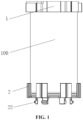
FIG. 1 is an assembly view of a battery cell and a battery cell mounting base according to some embodiments of the present application; -
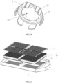
FIG. 2 is an assembly view of multiple groups of battery cells and battery cell mounting bases according to some embodiments of the present application; -
FIG. 3 is an enlarged view of part A inFIG. 2 ; -
FIG. 4 is a structural view of a lower cover from a perspective according to some embodiments of the present application; -
FIG. 5 is a structural view of a lower cover from another perspective according to some embodiments of the present application; -
FIG. 6 is a structural view of a battery module according to some embodiments of the present application; and -
FIG. 7 shows a structural view of a honeycomb panel and an enlarged view of part B of the honeycomb panel according to some embodiments of the present application. -
- 100
- battery cell
- 101
- first electrode
- 102
- second electrode
- 1
- upper cover
- 11
- first annular cylinder
- 12
- second annular cylinder
- 13
- connecting plate
- 14
- baffle plate
- 15
- second snap
- 16
- second clamping groove
- 2
- lower cover
- 21
- limit groove
- 22
- first snap
- 221
- first clamping groove
- 23
- first adhesive storage groove
- 24
- second adhesive storage groove
- 25
- limit protrusion
- 26
- bottom plate
- 27
- side plate
- 3
- battery box
- 4
- busbar
- 5
- honeycomb panel
- Embodiments of the present application are described hereinafter in conjunction with drawings. Based on the embodiments of the present application, all other embodiments obtained by those skilled in the art without creative work are within the scope of the present application.
- In the description of the present application, terms "joined", "connected", and "fixed" are to be understood in a broad sense unless otherwise expressly specified and limited. For example, the term "connected" may refer to "fixedly connected", "detachably connected" or "integrated", may refer to "mechanically connected" or "electrically connected", or may refer to "connected directly", "connected indirectly through an intermediary", or "connected inside two components" or an interaction relation between two components. For those of ordinary skill in the art, specific meanings of the preceding terms in the present application may be understood based on specific situations.
- In the present application, unless otherwise expressly specified and limited, when a first feature is described as "on" or "below" a second feature, the first feature and the second feature may be in direct contact or be in contact via another feature between the two features instead of being in direct contact. Moreover, when the first feature is described as "on", "above" or "over" the second feature, the first feature is right on, above or over the second feature, or the first feature is obliquely on, above or over the second feature, or the first feature is simply at a higher level than the second feature. When the first feature is described as "under", "below" or "underneath" the second feature, the first feature is right under, below or underneath the second feature, or the first feature is obliquely under, below or underneath the second feature, or the first feature is simply at a lower level than the second feature.
- An embodiment provides a battery cell mounting base. As shown in
FIG. 1 to FIG. 5 , the battery cell mounting base includes alower cover 2, thelower cover 2 has alimit groove 21 for accommodating abattery cell 100, thebattery cell 100 is secured in thelimit groove 21, a connecting portion is provided on a side of thelower cover 2 away from thebattery cell 100, and thelower cover 2 can be secured to abattery box 3 through the connecting portion. - The
limit groove 21 and the connecting portion are provided on thelower cover 2 for connectingsingle battery cells 100 and thebattery box 3.Multiple battery cells 100 can be spliced in thebattery box 3 through thelower cover 2. The number ofbattery cells 100 and the number oflower covers 2 can be set adaptively according to the capacity of a battery module and the size and shape of thebattery box 3. In this manner, thebattery cells 100 and thelower covers 2 can be freely matched for connection in series or parallel, and thus the grouping manner is more flexible and compatible. Thelower cover 2 has a small volume in structure and is easy to manufacture and mount, and thus costs are saved. Thelimit groove 21 of thelower cover 2 is configured to position the battery cell, improving the positioning accuracy. - In an embodiment, a
first electrode 101 and asecond electrode 102 of thebattery cell 100 are located on the same side, the battery cell mounting base further includes anupper cover 1 disposed opposite to thelower cover 2, theupper cover 1 covers the side of thebatter cell 100 where thefirst electrode 101 and thesecond electrode 102 are disposed, and thefirst electrode 101 and thesecond electrode 102 are exposed from theupper cover 1. - During assembly, two ends of the
battery cell 100 are connected to theupper cover 1 and thelower cover 2 respectively. For ease of description, thebattery cell 100 is mounted between theupper cover 1 and thelower cover 2 to form a battery cell group, which is simple in structure and easy to assemble. When the battery module includesmultiple battery cells 100, multiple battery cell mounting bases with the same number as thebattery cells 100 are disposed to form multiple battery cell groups, and then the multiple battery cell groups are secured to thebattery box 3 through thelower cover 2, so the connection reliability is improved. The battery cell groups can be spliced, and battery cell mounting bases are disposed according to the number ofbattery cells 100 in the battery module. In this manner, battery cells and battery cell mounting bases can be freely matched for connection in series or parallel, and thus the battery cell mounting bases are more compatible and are easy to mount. It is not necessary to customize the battery cell mounting base according to the model of the battery module, saving costs. For example, theupper cover 1 and thelower cover 2 may be manufactured according to the model of thebattery cell 100, and the same type ofbattery cell 100 can use the sameupper cover 1 and the samelower cover 2. Thus, mass production can be achieved, further reducing the costs and shortening the manufacturing period. Theupper cover 1 and thelower cover 2 are configured to not only protect but also limit thebattery cell 100, improving the reliability of the battery cells mounted in thebattery box 3. Thefirst electrode 101 and thesecond electrode 102 are exposed to facilitate the connection ofdifferent battery cells 100 in series or parallel through abusbar 4. - For example, the
upper cover 1 is a plastic cover, and thelower cover 2 is a plastic base. Theupper cover 1 and thelower cover 2 have the insulation function so that short circuits betweendifferent battery cells 100 can be prevented, and safety and reliability are improved. - In the embodiment, as shown in
FIG. 3 , thefirst electrode 101 is a negative electrode, and thesecond electrode 102 is a positive electrode. In other embodiments, thefirst electrode 101 may be a positive electrode, and thesecond electrode 102 may be a negative electrode. - In an embodiment, as shown in
FIG. 3 , thesecond electrode 102 protrudes from thefirst electrode 101. Theupper cover 1 includes a firstannular cylinder 11 and a secondannular cylinder 12 connected to a cylinder mouth at an end of the firstannular cylinder 11, the firstannular cylinder 11 is sleeved on an outer periphery of thebattery cell 100, the firstannular cylinder 11 is configured to limit thebattery cell 100 in the circumferential direction, and the secondannular cylinder 12 is sleeved on thesecond electrode 102 to avoid short circuits between thefirst electrode 101 and thesecond electrode 102 of thesame battery cell 100. For example, thefirst electrode 101 is exposed from the cylinder mouth of the firstannular cylinder 11, and thesecond electrode 102 is exposed from a cylinder mouth of the secondannular cylinder 12. - In an embodiment, the
battery cell 100 is cylindrical, an inner wall of the firstannular cylinder 11 is circular, and the shape of the inner wall of the firstannular cylinder 11 is adapted to the shape of the cylindrical battery cell, which improves the connection reliability and prevents shaking. When thebattery cell 100 is in other shapes, the shape of the inner wall of the firstannular cylinder 11 is set adaptively according to the shape of thebattery cell 100. Similarly, in an embodiment, thesecond electrode 102 is cylindrical, and an inner wall of the secondannular cylinder 12 is circular. - In an embodiment, as shown in
FIG. 3 , abaffle plate 14 is disposed at an end portion of the firstannular cylinder 11 to limit thebattery cell 100 relative to the direction of thelower cover 2. In the embodiment, thebattery cell 100 is cylindrical, thebaffle plate 14 is configured to axially limit the secondannular cylinder 12, the secondannular cylinder 12 is connected to thebaffle plate 14 through a connectingplate 13, and the connectingplate 13 and thebaffle plate 14 can abut against a part of thefirst electrode 101 so that the other part of thefirst electrode 101 is exposed. - In an embodiment, as shown in
FIG. 3 , asecond snap 15 and asecond clamping groove 16 are provided in a circumferential direction of the firstannular cylinder 11. Thesecond snap 15 of the firstupper cover 1 can be engaged with thesecond clamping groove 16 of an adjacentupper cover 1, and thesecond clamping groove 16 of the firstupper cover 1 can be engaged with thesecond snap 15 of the adjacentupper cover 1.Adjacent battery cells 100 are detachably connected through respectiveupper covers 1, which improves the reliability of the connection betweendifferent battery cells 100 and prevents short circuits. For example, thesecond snap 15 protrudes from a periphery surface of the firstannular cylinder 11 in a radial direction, and thesecond clamping groove 16 is recessed in the periphery surface of the firstannular cylinder 11 in the radial direction. - In an embodiment, the
second snap 15 and thesecond clamping groove 16 are disposed opposite to each other. Whenmultiple battery cells 100 are disposed in rows, thesecond snap 15 and thesecond clamping groove 16 disposed opposite to each other are connected to theupper covers 1 ofadjacent battery cells 100 on two sides in the same row respectively, so the reliability of connection between thebattery cells 100 in the same row is improved. - In an embodiment, a pair of
second snap 15 andsecond clamping groove 16 may be provided. In an embodiment, two pairs ofsecond snaps 15 and second clampinggrooves 16 may be provided, and thesecond snaps 15 and thesecond clamping grooves 16 are disposed opposite each other, so twoadjacent battery cells 100 in the same row can be connected throughupper covers 1, while twoadjacent battery cells 100 in the same column can be connected throughupper covers 1; thus, the reliability of connection between multiple rows and columns ofbattery cells 100 in thebattery box 3 can be improved. In an embodiment, three or more pairs ofsecond snaps 15 and second clampinggrooves 16 may be provided. In the embodiment, as shown inFIG. 3 , the shape of the cross-section of the outer periphery of theupper cover 1 is hexagonal, and three pairs ofsecond snaps 15 and second clampinggrooves 16 are provided on the outer periphery for engagement connection with adjacent upper covers 1. Six side surfaces of theupper cover 1 are all connected to adjacentupper covers 1, so mounting density is improved. - In an embodiment, a
first snap 22 is provided on one of thelower cover 2 or thebattery box 3, afirst clamping groove 221 is provided on the other one, and thefirst snap 22 is engaged with thefirst clamping groove 221, so the reliability of connection between thelower cover 2 and thebattery box 3 is improved, and the reliability of connection of thebattery cells 100 in thebattery box 3 is improved. Moreover, the detachable connection between thelower cover 2 and thebattery box 3 facilitates the disassembly and assembly. In the embodiment, as shown inFIG. 1 andFIG. 4 , thefirst snap 22 is provided on a bottom surface of thelower cover 2, so it facilitates inserting thelower cover 2 in thebattery box 3 for mounting. - In an embodiment, a first
adhesive storage groove 23 is opened on an inner wall of thelimit groove 21. After the firstadhesive storage groove 23 is filled with structural adhesive, thebattery cell 100 is bonded in thelimit groove 21, which improves the reliability of mounting between thebattery cell 100 and thelower cover 2. In an embodiment, as shown inFIG. 5 , the firstadhesive storage groove 23 is opened on a bottom wall of thelimit groove 21. Similarly, in an embodiment, a secondadhesive storage groove 24 is provided on the side of thelower cover 2 away from thebattery cell 100, and when filled with structural adhesive, the secondadhesive storage groove 24 can bond thelower cover 2 and thebattery box 3, so mounting between thelower cover 2 and thebattery box 3 is more reliable. In the embodiment, as shown inFIG. 4 , the secondadhesive storage groove 24 is disposed on the bottom surface of thelower cover 2. - In an embodiment, the
lower cover 2 includes abottom plate 26 andmultiple side plates 27 annularly connected to an outer periphery of thebottom plate 26 and disposed at intervals, and thebottom plate 26 and themultiple side plates 27 form thelimit groove 21, so the weight of thelower cover 2 is reduced. In an embodiment, alimit protrusion 25 is provided on an outer periphery surface of eachside plate 27 for circumferential limiting. - The embodiment provides a battery module. As shown in
FIG. 2 , the battery module includes abattery box 3, abusbar 4,battery cells 100 and the preceding battery cell mounting base.Multiple battery cells 100 and multiple battery cell mounting bases are disposed, and thebusbar 4 is connected to thefirst electrode 101 of onebattery cell 100 and thesecond electrode 102 of anotherbatter cell 100 to achieve parallel connection of twobattery cells 100. Battery cell groups can be spliced, and battery cell mounting bases are disposed according to the number ofbattery cells 100 in the battery module. In this manner, battery cells and battery cell mounting bases can be freely matched for connection in series or parallel, and thus the battery cell mounting bases are more compatible and easy to mount. It is not necessary to customize the battery cell mounting base according to the model of the battery module, saving the costs. - In an embodiment, a
honeycomb panel 5 is disposed inside thebattery box 3, and thelower cover 2 is mounted in an accommodation groove of thehoneycomb panel 5 to prevent thelower cover 2 from moving. - In the embodiment, the second
adhesive storage groove 24 is opened on thelower cover 2. When structural adhesive is applied to the secondadhesive storage groove 24, thelower cover 2 can be bonded in the accommodation groove, so thelower cover 2 is secured more firmly to thehoneycomb panel 5. - In the embodiment, limit
protrusions 25 are provided on the outer periphery of thelower cover 2, and recesses matching the limit protrusions are provided on a groove side wall of the accommodation groove, so the circumferential rotation of thelower cover 2 can be limited, and thus the reliability of mounting can be improved. In this manner, no recess is provided on thelower cover 2 which is thin in structure, so the impact on the structural strength is avoided. - In the embodiment, a first clamping groove is provided on a groove bottom of the accommodation groove, and the
first snap 22 on thelower cover 2 is engaged with the first clamping groove. - In an embodiment, reference may be made to the structure of the battery module shown in
FIG. 6 and the structure of the honeycomb panel shown inFIG. 7 .
Claims (19)
- A battery cell mounting base, comprising a lower cover (2), wherein the lower cover (2) has a limit groove (21) for accommodating a battery cell (100), the battery cell (100) is secured in the limit groove (21), a connecting portion is provided on a side of the lower cover (2) away from the battery cell (100), and the lower cover (2) is secured to a battery box (3) through the connecting portion.
- The battery cell mounting base according to claim 1, wherein a first snap (22) is provided on one of the lower cover (2) or the battery box (3), a first clamping groove (221) is provided on the other one of the lower cover (2) or the battery box (3), the first snap (22) is engaged with the first clamping groove (221), and the connecting portion is the first snap (22) or the first clamping groove (221) which is provided on the lower cover (2).
- The battery cell mounting base according to claim 1, wherein the connecting portion is disposed on a bottom surface of the lower cover (2).
- The battery cell mounting base according to claim 1, wherein a first adhesive storage groove (23) is opened on an inner wall of the limit groove (21).
- The battery cell mounting base according to claim 4, wherein the first adhesive storage groove (23) is opened on a bottom wall of the limit groove (21).
- The battery cell mounting base according to claim 4, wherein a second adhesive storage groove (24) is provided on the side of the lower cover (2) away from the battery cell (100), and the second adhesive storage groove (24) filled with structural adhesive is capable of bonding the lower cover (2) and the battery box (3).
- The battery cell mounting base according to claim 6, wherein the second adhesive storage groove (24) is disposed on a bottom surface of the lower cover (2).
- The battery cell mounting base according to claim 1, wherein the lower cover (2) comprises a bottom plate (26) and a plurality of side plates (27) annularly arranged and connected to an outer periphery of the bottom plate (26), the plurality of side plates (27) are disposed at intervals, and the bottom plate (26) and the plurality of side plates (27) are encircled to form the limit groove (21).
- The battery cell mounting base according to claim 8, wherein a limit protrusion (25) is provided on an outer periphery surface of each of the plurality of side plates (27).
- The battery cell mounting base according to any one of claims 1 to 9, wherein a first electrode (101) and a second electrode (102) of the battery cell (100) are located on a same side of the battery cell (100), the battery cell mounting base further comprises an upper cover (1) disposed opposite to the lower cover (2), the upper cover (1) covers the side of the batter cell (100) where the first electrode (101) and the second electrode (102) are disposed, and the first electrode (101) and the second electrode (102) are exposed from the upper cover (1).
- The battery cell mounting base according to claim 10, wherein the second electrode (102) protrudes from the first electrode (101), the upper cover (1) comprises a first annular cylinder (11) and a second annular cylinder (12) connected to a cylinder mouth at an end of the first annular cylinder (11), the first annular cylinder (11) is sleeved on an outer periphery of the battery cell (100), the second annular cylinder (12) is sleeved on the second electrode (102), the first electrode (101) is exposed from the cylinder mouth of the first annular cylinder (11), and the second electrode (102) is exposed from a cylinder mouth of the second annular cylinder (12).
- The battery cell mounting base according to claim 11, wherein a baffle plate (14) is disposed at an end portion of the first annular cylinder (11), the second annular cylinder (12) is connected to the baffle plate (14) through a connecting plate (13), and the connecting plate (13) and the baffle plate (14) abut against a part of the first electrode (101).
- The battery cell mounting base according to claim 11, wherein the battery cell (100) is a cylindrical battery cell, and an inner wall of the first annular cylinder (11) is circular.
- The battery cell mounting base according to claim 11, wherein the second electrode (102) is cylindrical, and an inner wall of the second annular cylinder (12) is circular.
- The battery cell mounting base according to claim 13, wherein the second electrode (102) is cylindrical, and an inner wall of the second annular cylinder (12) is circular.
- The battery cell mounting base according to claim 11, wherein a second snap and a second clamping groove (16) are provided in a circumferential direction of the first annular cylinder (11).
- The battery cell mounting base according to claim 16, wherein the second snap (15) and the second clamping groove (16) are disposed opposite to each other.
- A battery module, comprising a battery box (3), a busbar (4), a battery cell (100) and the battery cell mounting base according to any one of claims 1 to 17, wherein a plurality of battery cells (100) and a plurality of battery cell mounting bases are provided, and the busbar (4) is connected to a first electrode (101) of a battery cell (100) among the plurality of battery cells (100) and a second electrode (102) of another battery cell (100) among the plurality of battery cells (100).
- The battery module according to claim 18, wherein a honeycomb panel (5) is disposed inside the battery box (3), and the lower cover (2) is mounted in an accommodating groove of the honeycomb panel (5).
Applications Claiming Priority (2)
| Application Number | Priority Date | Filing Date | Title |
|---|---|---|---|
| CN202220840901.1U CN217788688U (en) | 2022-04-12 | 2022-04-12 | Electricity core mount pad and battery module |
| PCT/CN2022/126172 WO2023197555A1 (en) | 2022-04-12 | 2022-10-19 | Battery cell mounting base and battery module |
Publications (2)
| Publication Number | Publication Date |
|---|---|
| EP4510340A1 true EP4510340A1 (en) | 2025-02-19 |
| EP4510340A4 EP4510340A4 (en) | 2025-08-20 |
Family
ID=83907829
Family Applications (1)
| Application Number | Title | Priority Date | Filing Date |
|---|---|---|---|
| EP22937188.5A Pending EP4510340A4 (en) | 2022-04-12 | 2022-10-19 | BATTERY CELL MOUNTING BASE AND BATTERY MODULE |
Country Status (5)
| Country | Link |
|---|---|
| US (1) | US20250038335A1 (en) |
| EP (1) | EP4510340A4 (en) |
| CN (1) | CN217788688U (en) |
| DE (1) | DE212022000400U1 (en) |
| WO (1) | WO2023197555A1 (en) |
Families Citing this family (2)
| Publication number | Priority date | Publication date | Assignee | Title |
|---|---|---|---|---|
| USD1102371S1 (en) * | 2023-12-29 | 2025-11-18 | Huizhou Eve Power Co., Ltd | Battery |
| EP4601089A1 (en) | 2024-02-06 | 2025-08-13 | LG Energy Solution, Ltd. | Battery cell assembly, battery pack, and transportation device comprising the same |
Family Cites Families (6)
| Publication number | Priority date | Publication date | Assignee | Title |
|---|---|---|---|---|
| TWM337852U (en) * | 2008-03-11 | 2008-08-01 | Welldone Company | Battery assembly rack |
| DE102015011898A1 (en) * | 2015-04-14 | 2016-10-20 | EsprlTschmiede GbR (vertretungsberechtigter Gesellschafter: Sebastian Prengel, 01067 Dresden) | Energy storage device and cell holder for an energy storage device |
| DE202017103801U1 (en) * | 2017-06-26 | 2018-10-01 | SOLO Vertriebs- und Entwicklungs-GmbH | Retaining element for a battery cell assembly |
| KR102203249B1 (en) * | 2017-10-10 | 2021-01-13 | 주식회사 엘지화학 | Cylindrical Battery Cell Having Connection Cap |
| CN208939064U (en) * | 2018-07-26 | 2019-06-04 | 北京长城华冠汽车科技股份有限公司 | Splicing Modules, Single String Modules and Cylindrical Cell Modules for Cylindrical Cells |
| KR102906602B1 (en) * | 2019-01-29 | 2025-12-30 | 나라분다 테크놀로지 홀딩스 피티와이 엘티디 | battery pack |
-
2022
- 2022-04-12 CN CN202220840901.1U patent/CN217788688U/en active Active
- 2022-10-19 DE DE212022000400.0U patent/DE212022000400U1/en active Active
- 2022-10-19 WO PCT/CN2022/126172 patent/WO2023197555A1/en not_active Ceased
- 2022-10-19 EP EP22937188.5A patent/EP4510340A4/en active Pending
-
2024
- 2024-10-14 US US18/914,675 patent/US20250038335A1/en active Pending
Also Published As
| Publication number | Publication date |
|---|---|
| DE212022000400U1 (en) | 2024-12-23 |
| US20250038335A1 (en) | 2025-01-30 |
| CN217788688U (en) | 2022-11-11 |
| WO2023197555A1 (en) | 2023-10-19 |
| EP4510340A4 (en) | 2025-08-20 |
Similar Documents
| Publication | Publication Date | Title |
|---|---|---|
| US20250038335A1 (en) | Battery cell mounting base and battery module | |
| KR100850866B1 (en) | Frame member for battery pack manufacturing | |
| EP1984965B1 (en) | Spacer for production of battery pack | |
| EP2571078B1 (en) | Battery module | |
| EP1969655B1 (en) | Frame member and battery pack employed with the same | |
| CN217158579U (en) | Insulating support and battery module | |
| EP0612116B1 (en) | Support extension for flat pack rechargeable batteries | |
| JP6752674B2 (en) | Battery pack | |
| JP5423067B2 (en) | Battery module and manufacturing method thereof | |
| KR20160094235A (en) | Energy storage device | |
| US20120219846A1 (en) | Battery cell support and assembly thereof | |
| US20260011852A1 (en) | Energy storage power supply | |
| KR20110131609A (en) | Battery pack | |
| CN207572443U (en) | battery pack | |
| CN116941121A (en) | Battery and electric equipment | |
| KR20170067007A (en) | Compact secondary battery module integrated with BMS | |
| US20220123414A1 (en) | Partition plate, battery module, battery pack, and device | |
| US20240120591A1 (en) | Battery cell module and battery system | |
| JP2008097942A (en) | Battery pack | |
| US20240120600A1 (en) | Battery cell module and battery system | |
| US20240243418A1 (en) | Battery module, battery pack, and vehicle | |
| CN212648411U (en) | Battery pack and combined power supply | |
| CN216958287U (en) | Battery pack and casing thereof | |
| EP4246675A1 (en) | Battery cell module and battery system | |
| CN218586155U (en) | Battery pack |
Legal Events
| Date | Code | Title | Description |
|---|---|---|---|
| STAA | Information on the status of an ep patent application or granted ep patent |
Free format text: STATUS: THE INTERNATIONAL PUBLICATION HAS BEEN MADE |
|
| PUAI | Public reference made under article 153(3) epc to a published international application that has entered the european phase |
Free format text: ORIGINAL CODE: 0009012 |
|
| STAA | Information on the status of an ep patent application or granted ep patent |
Free format text: STATUS: REQUEST FOR EXAMINATION WAS MADE |
|
| 17P | Request for examination filed |
Effective date: 20241112 |
|
| AK | Designated contracting states |
Kind code of ref document: A1 Designated state(s): AL AT BE BG CH CY CZ DE DK EE ES FI FR GB GR HR HU IE IS IT LI LT LU LV MC ME MK MT NL NO PL PT RO RS SE SI SK SM TR |
|
| DAV | Request for validation of the european patent (deleted) | ||
| DAX | Request for extension of the european patent (deleted) | ||
| A4 | Supplementary search report drawn up and despatched |
Effective date: 20250721 |
|
| RIC1 | Information provided on ipc code assigned before grant |
Ipc: H01M 50/289 20210101AFI20250715BHEP Ipc: H01M 50/204 20210101ALI20250715BHEP Ipc: H01M 50/505 20210101ALI20250715BHEP Ipc: H01M 50/264 20210101ALI20250715BHEP Ipc: H01M 50/244 20210101ALI20250715BHEP Ipc: H01M 50/258 20210101ALI20250715BHEP Ipc: H01M 50/267 20210101ALI20250715BHEP Ipc: H01M 50/213 20210101ALI20250715BHEP |