EP4510326A1 - Battery cell, battery, and electrical device - Google Patents
Battery cell, battery, and electrical device Download PDFInfo
- Publication number
- EP4510326A1 EP4510326A1 EP22963918.2A EP22963918A EP4510326A1 EP 4510326 A1 EP4510326 A1 EP 4510326A1 EP 22963918 A EP22963918 A EP 22963918A EP 4510326 A1 EP4510326 A1 EP 4510326A1
- Authority
- EP
- European Patent Office
- Prior art keywords
- housing
- cover plate
- battery cell
- battery
- bottom wall
- Prior art date
- Legal status (The legal status is an assumption and is not a legal conclusion. Google has not performed a legal analysis and makes no representation as to the accuracy of the status listed.)
- Pending
Links
Images





Classifications
-
- H—ELECTRICITY
- H01—ELECTRIC ELEMENTS
- H01M—PROCESSES OR MEANS, e.g. BATTERIES, FOR THE DIRECT CONVERSION OF CHEMICAL ENERGY INTO ELECTRICAL ENERGY
- H01M50/00—Constructional details or processes of manufacture of the non-active parts of electrochemical cells other than fuel cells, e.g. hybrid cells
- H01M50/10—Primary casings; Jackets or wrappings
- H01M50/14—Primary casings; Jackets or wrappings for protecting against damage caused by external factors
-
- H—ELECTRICITY
- H01—ELECTRIC ELEMENTS
- H01M—PROCESSES OR MEANS, e.g. BATTERIES, FOR THE DIRECT CONVERSION OF CHEMICAL ENERGY INTO ELECTRICAL ENERGY
- H01M50/00—Constructional details or processes of manufacture of the non-active parts of electrochemical cells other than fuel cells, e.g. hybrid cells
- H01M50/10—Primary casings; Jackets or wrappings
- H01M50/102—Primary casings; Jackets or wrappings characterised by their shape or physical structure
- H01M50/103—Primary casings; Jackets or wrappings characterised by their shape or physical structure prismatic or rectangular
-
- H—ELECTRICITY
- H01—ELECTRIC ELEMENTS
- H01M—PROCESSES OR MEANS, e.g. BATTERIES, FOR THE DIRECT CONVERSION OF CHEMICAL ENERGY INTO ELECTRICAL ENERGY
- H01M50/00—Constructional details or processes of manufacture of the non-active parts of electrochemical cells other than fuel cells, e.g. hybrid cells
- H01M50/10—Primary casings; Jackets or wrappings
- H01M50/147—Lids or covers
- H01M50/148—Lids or covers characterised by their shape
- H01M50/15—Lids or covers characterised by their shape for prismatic or rectangular cells
-
- H—ELECTRICITY
- H01—ELECTRIC ELEMENTS
- H01M—PROCESSES OR MEANS, e.g. BATTERIES, FOR THE DIRECT CONVERSION OF CHEMICAL ENERGY INTO ELECTRICAL ENERGY
- H01M50/00—Constructional details or processes of manufacture of the non-active parts of electrochemical cells other than fuel cells, e.g. hybrid cells
- H01M50/10—Primary casings; Jackets or wrappings
- H01M50/147—Lids or covers
- H01M50/155—Lids or covers characterised by the material
- H01M50/157—Inorganic material
- H01M50/159—Metals
-
- H—ELECTRICITY
- H01—ELECTRIC ELEMENTS
- H01M—PROCESSES OR MEANS, e.g. BATTERIES, FOR THE DIRECT CONVERSION OF CHEMICAL ENERGY INTO ELECTRICAL ENERGY
- H01M50/00—Constructional details or processes of manufacture of the non-active parts of electrochemical cells other than fuel cells, e.g. hybrid cells
- H01M50/10—Primary casings; Jackets or wrappings
- H01M50/147—Lids or covers
- H01M50/155—Lids or covers characterised by the material
- H01M50/16—Organic material
-
- H—ELECTRICITY
- H01—ELECTRIC ELEMENTS
- H01M—PROCESSES OR MEANS, e.g. BATTERIES, FOR THE DIRECT CONVERSION OF CHEMICAL ENERGY INTO ELECTRICAL ENERGY
- H01M50/00—Constructional details or processes of manufacture of the non-active parts of electrochemical cells other than fuel cells, e.g. hybrid cells
- H01M50/10—Primary casings; Jackets or wrappings
- H01M50/147—Lids or covers
- H01M50/166—Lids or covers characterised by the methods of assembling casings with lids
- H01M50/169—Lids or covers characterised by the methods of assembling casings with lids by welding, brazing or soldering
-
- H—ELECTRICITY
- H01—ELECTRIC ELEMENTS
- H01M—PROCESSES OR MEANS, e.g. BATTERIES, FOR THE DIRECT CONVERSION OF CHEMICAL ENERGY INTO ELECTRICAL ENERGY
- H01M50/00—Constructional details or processes of manufacture of the non-active parts of electrochemical cells other than fuel cells, e.g. hybrid cells
- H01M50/10—Primary casings; Jackets or wrappings
- H01M50/172—Arrangements of electric connectors penetrating the casing
- H01M50/174—Arrangements of electric connectors penetrating the casing adapted for the shape of the cells
- H01M50/176—Arrangements of electric connectors penetrating the casing adapted for the shape of the cells for prismatic or rectangular cells
-
- H—ELECTRICITY
- H01—ELECTRIC ELEMENTS
- H01M—PROCESSES OR MEANS, e.g. BATTERIES, FOR THE DIRECT CONVERSION OF CHEMICAL ENERGY INTO ELECTRICAL ENERGY
- H01M50/00—Constructional details or processes of manufacture of the non-active parts of electrochemical cells other than fuel cells, e.g. hybrid cells
- H01M50/20—Mountings; Secondary casings or frames; Racks, modules or packs; Suspension devices; Shock absorbers; Transport or carrying devices; Holders
- H01M50/204—Racks, modules or packs for multiple batteries or multiple cells
- H01M50/207—Racks, modules or packs for multiple batteries or multiple cells characterised by their shape
- H01M50/209—Racks, modules or packs for multiple batteries or multiple cells characterised by their shape adapted for prismatic or rectangular cells
-
- H—ELECTRICITY
- H01—ELECTRIC ELEMENTS
- H01M—PROCESSES OR MEANS, e.g. BATTERIES, FOR THE DIRECT CONVERSION OF CHEMICAL ENERGY INTO ELECTRICAL ENERGY
- H01M50/00—Constructional details or processes of manufacture of the non-active parts of electrochemical cells other than fuel cells, e.g. hybrid cells
- H01M50/50—Current conducting connections for cells or batteries
- H01M50/543—Terminals
- H01M50/547—Terminals characterised by the disposition of the terminals on the cells
- H01M50/55—Terminals characterised by the disposition of the terminals on the cells on the same side of the cell
-
- H—ELECTRICITY
- H01—ELECTRIC ELEMENTS
- H01M—PROCESSES OR MEANS, e.g. BATTERIES, FOR THE DIRECT CONVERSION OF CHEMICAL ENERGY INTO ELECTRICAL ENERGY
- H01M2220/00—Batteries for particular applications
- H01M2220/20—Batteries in motive systems, e.g. vehicle, ship, plane
-
- Y—GENERAL TAGGING OF NEW TECHNOLOGICAL DEVELOPMENTS; GENERAL TAGGING OF CROSS-SECTIONAL TECHNOLOGIES SPANNING OVER SEVERAL SECTIONS OF THE IPC; TECHNICAL SUBJECTS COVERED BY FORMER USPC CROSS-REFERENCE ART COLLECTIONS [XRACs] AND DIGESTS
- Y02—TECHNOLOGIES OR APPLICATIONS FOR MITIGATION OR ADAPTATION AGAINST CLIMATE CHANGE
- Y02E—REDUCTION OF GREENHOUSE GAS [GHG] EMISSIONS, RELATED TO ENERGY GENERATION, TRANSMISSION OR DISTRIBUTION
- Y02E60/00—Enabling technologies; Technologies with a potential or indirect contribution to GHG emissions mitigation
- Y02E60/10—Energy storage using batteries
Definitions
- This application relates to the technical field of batteries, and in particular, to a battery cell, a battery, and an electrical device.
- the battery is mounted in an electrical device such as a vehicle. Because the movement of the vehicle causes some impact on the battery, the structure of a battery cell in the battery directly affects the safety of the battery. Therefore, how to improve the structure of the battery cell to enhance the safety of the battery cell has become a problem to be solved.
- This application provides a battery cell, a battery, and an electrical device, and enhances safety of the battery cell by improving the structure of the battery cell.
- a battery cell includes: a housing, on which an opening is created; an electrode assembly, accommodated in the housing; an electrode terminal, disposed on a bottom wall of the housing and connected to a tab of the electrode assembly, where the bottom wall is opposite to the opening; and a cover plate, connected to the housing and configured to fit and cover the opening.
- the electrode terminal is disposed on the bottom wall of the housing, and the cover plate is connected to the housing and fits and covers the opening of the housing, and therefore, a junction between the cover plate and the housing is located on the opposite side of the electrode terminal, and the junction between the cover plate and the housing is relatively far away from the electrode terminal.
- the battery cell is disposed in a box of a battery, and the cover plate is fixed to a wall of the box.
- the cover plate of the battery cell is fixed to the wall of the box, thereby reducing the impact on the junction between the cover plate and the housing, and enhancing the safety of the battery cell.
- the box contains a plurality of the battery cells. Sidewalls of the housings of adjacent battery cells are fixed to each other. When the battery cells are assembled to form a battery, the adjacent battery cells are fixed to each other, thereby ensuring stability of the junction between the cover plate and the housing, and enhancing the safety of the battery cell.
- the cover plate is located below the bottom wall when the battery is disposed in an electrical device.
- the battery cells are positioned "upright". In this way, when a chassis of a vehicle is impacted during movement of the vehicle or when another emergency occurs, because the electrode terminals of the battery cell face upward, the above arrangement reduces the damage to the electrode terminals caused by the impact or other emergencies, and ensures safety of the battery.
- a thickness of the bottom wall is greater than a thickness of the cover plate.
- the relatively large thickness of the bottom wall ensures sufficient strength of the bottom wall, and enables the electrode terminal to be stably fixed on the bottom wall.
- the relatively small thickness of the cover plate reduces the weight and volume of the battery cell, and increases the energy density of the battery cell.
- a thickness of the bottom wall is greater than 0.1 mm and less than or equal to 5 mm, thereby not only ensuring sufficient strength of the bottom wall, but also avoiding an unnecessary increase in weight and volume, and ensuring relatively high structural stability of the battery cell.
- a thickness of the cover plate is greater than or equal to 0.1 mm and less than or equal to 3 mm, thereby reducing the weight and volume of the battery cell but without increasing the difficulty of connection between the cover plate and the housing.
- the cover plate is made of a metal material or a polymer material. Such materials are easily achievable and ensure sufficient strength of the cover plate.
- the cover plate is welded to the housing.
- the connection implemented by welding exhibits the advantages of good connection performance, high airtightness and watertightness, and easy operation and implementation, thereby not only implementing the connection between the cover plate and the housing, but also improving the hermeticity of the junction between the cover plate and the housing.
- the cover plate is welded to the housing by laser welding.
- Laser welding exhibits the advantages of fast speed, large depth, narrow weld seams, and resistance to deformation, and is especially suitable for a safety-demanding scenarios such as batteries, and can implement reliable welding between the housing and the cover plate of the battery cell.
- a blocking structure is disposed in the opening of the housing.
- the blocking structure is configured to limit a depth by which the cover plate enters the housing in a first direction perpendicular to the bottom wall. Because the blocking structure constrains the cover plate in the first direction, the cover plate is not prone to wobble in the first direction X in a process of connecting the cover plate to the housing.
- the blocking structure is a ramp formed on a surface of a sidewall of the housing, the surface being oriented toward an interior of the housing.
- a dimension of the cover plate in a second direction perpendicular to the sidewall falls between a first distance and a second distance.
- the first distance and the second distance are a minimum distance and a maximum distance between two opposite ramps in the second direction respectively.
- the blocking structure is a step formed on a surface of a sidewall of the housing, the surface being oriented toward an interior of the housing.
- the cover plate is disposed on the step. In this way, when the cover plate fits and covers the opening along the first direction, because the edge of the cover plate laps the step face, the step can limit the depth by which the cover plate enters the housing, so that the cover plate is constrained in the first direction, and the cover plate is not prone to wobble in the first direction in a process of connecting the cover plate to the housing.
- a weld seam between the cover plate and the housing is perpendicular to the bottom wall.
- a weld mark formed by welding between the cover plate and the housing exceeds the sidewall in the first direction by a margin less than or equal to 0.5 mm, and the weld mark exceeds the sidewall in the second direction by a margin less than or equal to 0.08 mm. In this way, this avoids interference between the weld mark and other surrounding structural components, and avoids an impact on other structural components, where the weld mark is formed by welding between the cover plate and the housing.
- the cover plate includes a first part and a second part.
- a dimension of the second part in a second direction perpendicular to a sidewall of the housing is greater than a dimension of the first part in the second direction.
- the first part is accommodated in the opening.
- An edge of the second part abuts on an end face of the sidewall, the end face being oriented away from the bottom wall.
- a weld seam between the cover plate and the housing is perpendicular to the sidewall.
- a weld mark formed by welding between the cover plate and the housing exceeds the sidewall in the first direction by a margin less than or equal to 0.5 mm, and the weld mark exceeds the sidewall in the second direction by a margin less than or equal to 0.08 mm. In this way, this avoids interference between the weld mark and other surrounding structural components, and avoids an impact on other structural components, where the weld mark is formed by welding between the cover plate and the housing.
- an injection hole configured to inject an electrolyte solution is further created on the bottom wall, thereby facilitating injection of the electrolyte solution into the battery cell.
- an electrode lead-out hole is further created on the bottom wall.
- the electrode terminal is mounted in the electrode lead-out hole.
- the electrode lead-out hole facilitates electrical connection between a tab of the electrode assembly and the electrode terminal, so that a current of the tab can be led from the electrode lead-out hole to the electrode terminal.
- a pressure relief mechanism is disposed on the cover plate.
- the pressure relief mechanism is configured to release an internal pressure of the battery cell when the internal pressure exceeds a threshold.
- the electrode terminal of the battery cell is disposed on the bottom wall of the housing, and the pressure relief mechanism is disposed on the cover plate opposite to the bottom wall.
- the pressure relief mechanism and the electrode terminal are disposed on different walls of the battery cell. In this way, the emissions in the battery cell are farther away from the electrode terminal, thereby reducing the impact of the emissions on the electrode terminal and busbar component, and further enhancing the safety of the battery.
- a battery including: a plurality of battery cells disclosed in the first aspect or any implementation of the first aspect; and a box, configured to accommodate the plurality of the battery cells, where the cover plate of the battery cell is fixed to the wall of the box.
- sidewalls of the housings of adjacent battery cells in the box are fixed to each other.
- the cover plate of the battery cell is located below the bottom wall of the housing of the battery cell when the battery is disposed in an electrical device.
- an electrical device including the battery disclosed in the second aspect or any implementation of the second aspect.
- the battery is configured to provide electrical energy.
- a plurality of means at least two in number; the terms such as “up”, “down”, “left”, “right”, “in”, and “out” indicating a direction or a position relationship are merely intended for ease or brevity of description of this application, but do not indicate or imply that the mentioned device or component is necessarily located in the specified direction and position or constructed or operated in the specified direction and position. Therefore, such terms are not to be understood as a limitation on this application.
- the terms “first”, “second”, “third”, and so on are merely used for descriptive purposes, but not construed as indicating or implying relative importance.
- Perfect does not means exact perpendicularity, but means perpendicularity falling within an error tolerance range.
- Parallel does not mean exact parallelism, but means parallelism falling within an error tolerance range.
- connection may be a fixed connection, a detachable connection, or an integrated connection, and may be a direct connection or an indirect connection implemented through an intermediary.
- a battery means a physical module that includes one or more battery cells to provide electrical energy.
- the battery in this application may include a battery module, a battery pack, or the like.
- a battery typically includes a box configured to package one or more battery cells. The box prevents liquid or other foreign matters from affecting the charging or discharging of the battery cells.
- a battery cell may include types such as a lithium-ion secondary battery, a lithium-ion primary battery, a lithium-sulfur battery, a sodium-lithium-ion battery, a sodium-ion battery, or a magnesium-ion battery.
- the type of the battery cell is not limited herein.
- the battery cell is also referred to as a cell.
- a plurality of battery cells in a battery may be connected in series, parallel, or series-and-parallel pattern.
- the series-and-parallel pattern means a combination of series connection and parallel connection.
- the plurality of battery cells may be connected in series, parallel, or series-and-parallel pattern to form a battery module, and then a plurality of battery modules may be connected in series, parallel, or series-and-parallel pattern to form the battery.
- the plurality of battery cells may directly form the battery, or form the battery modules that are then used to form the battery.
- the battery is further mounted in the electrical device to provide electrical energy for the electrical device.
- the battery box may further include a signal transmission assembly.
- the signal transmission assembly may be configured to transmit signals such as voltage and/or temperature of the battery cell.
- the signal transmission assembly may include a busbar component.
- the busbar component is configured to implement electrical connection, such as parallel connection, series connection, or series-and-parallel connection, between a plurality of battery cells.
- the busbar component may implement electrical connection between the battery cells by connecting electrode terminals of the battery cells.
- the busbar component may be fixed to the electrode terminals of the battery cell by welding.
- the busbar component transmits the voltage of the battery cell. A plurality of battery cells are connected in series to obtain a higher voltage.
- an electrical connection formed by the busbar component may be referred to as a "high-voltage connection".
- the signal transmission assembly may further include, in addition to the busbar component, a sensor device configured to sense the status of a battery cell.
- the sensor device may be configured to measure and transmit sensed signals such as temperature and state of charge of the battery cell.
- the busbar component and the sensor device may be packaged in an insulation layer to form the signal transmission assembly. Accordingly, the signal transmission assembly may be configured to transmit voltage and/or sensed signals of the battery cell. No insulation layer is disposed at a junction between the signal transmission assembly and the electrode terminal of the battery cell. In other words, the insulation layer is opened at the junction to enable connection to the electrode terminal of the battery cell.
- a battery cell includes an electrode assembly and an electrolytic solution.
- the electrode assembly includes a positive electrode plate, a negative electrode plate, and a separator.
- the battery cell works primarily by relying on shuttling of metal ions between the positive electrode plate and the negative electrode plate.
- the positive electrode plate includes a positive current collector and a positive active material layer. A surface of the positive current collector is coated with the positive active material layer. Of the current collector, a part not coated with the positive active material layer protrudes from a part coated with the positive active material layer, and the part not coated with the positive active material layer serves as a positive tab.
- the positive current collector may be made of aluminum, and a positive active material may be lithium cobalt oxide, lithium iron phosphate, ternary lithium, lithium manganese oxide, or the like.
- the negative electrode plate includes a negative current collector and a negative active material layer. A surface of the negative current collector is coated with the negative active material layer. Of the current collector, a part not coated with the negative active material layer protrudes from a part coated with the negative active material layer, and the part not coated with the negative active material layer serves as a negative tab.
- the negative current collector may be made of copper, and a negative active material may be carbon, silicon, or the like.
- the separator may be made of a material such as polypropylene (polypropylene, PP) or polyethylene (polyethylene, PE).
- the electrode assembly may be of a jelly-roll type structure or a stacked type structure, without being limited herein.
- the battery cell further includes a housing and an end cap.
- the housing includes an opening.
- the end cap is configured to fit and cover the opening of the housing, so as to combine with the housing to form an accommodation space.
- the accommodation space is configured to accommodate the electrode assembly and an electrolyte solution.
- the electrode assembly may be mounted into the housing through the opening of the housing, and then the end cap is connected to the housing to seal the opening of the housing.
- the battery cell is usually further fitted with an electrode terminal.
- the electrode terminal is configured to electrically connect the electrode assembly to an external circuit to implement charging and discharging of the electrode assembly.
- the electrode terminal In a battery, the electrode terminal needs to be connected to external components such as a busbar component and a detection harness. When a battery cell is subjected to an external impact, the external components pull the electrode terminal.
- the electrode terminal In the related art, the electrode terminal is usually mounted on the end cap. When an external component exerts a pushing or pulling force or a twisting force on the electrode terminal, the force is applied to the junction between the end cap and the housing accordingly.
- the long-term fatigue stress at the junction between the end cap and the housing may eventually result in a crack, cause failure of the connection between the end cap and the housing, give rise to risks such as electrolyte leakage or even fire, and pose safety hazards.
- this application provides a technical solution.
- the end cap is replaced with a cover plate.
- the cover plate is configured to fit and cover the opening of the housing.
- the spacecraft includes an airplane, a rocket, a space shuttle, a spaceship, and the like.
- the vehicle may be an oil-fueled vehicle, a natural gas vehicle, or a new energy vehicle.
- the new energy vehicle may be a battery electric vehicle, a hybrid electric vehicle, a range-extended electric vehicle, or the like.
- the spacecraft includes an airplane, a rocket, a space shuttle, a spaceship, and the like.
- the electric toy includes a fixed or mobile electric toy, such as a game console, an electric car toy, an electric ship toy, an electric airplane toy, and the like.
- the power tool includes an electrical metal cutting tool, an electrical grinding tool, an electrical assembling tool, and a power tool for use in railways. Examples of the power tool are an electrical drill, an electrical grinder, an electrical wrench, an electrical screwdriver, an electrical hammer, an electrical impact drill, a concrete vibrator, an electrical planer, and the like.
- the electrical device is not particularly limited in embodiments of this application.
- the vehicle 1 may be an oil-fueled vehicle, a natural gas vehicle, or a new energy vehicle.
- the new energy vehicle may be a battery electric vehicle, a hybrid electric vehicle, a range-extended electric vehicle, or the like.
- a motor 40, a controller 30, and a battery 10 may be disposed inside the vehicle 1.
- the controller 30 is configured to control the battery 10 to supply power to the motor 40.
- the battery 10 may be disposed at the bottom, front, or rear of the vehicle 1.
- the battery 10 may be configured to supply power to the vehicle 1.
- the battery 10 may serve as an operating power supply of the vehicle 1 to power a circuit system of the vehicle 1.
- the battery may be configured to meet operating power usage requirements of the vehicle 1 that is being started or navigated or running.
- the battery 10 serves not only as an operating power supply of the vehicle 1, but may also serve as a driving power supply of the vehicle 1 to provide driving power for the vehicle 1 in place of or partly in place of fuel oil or natural gas.
- the battery 10 may include a plurality of battery cells.
- FIG. 2 which is a schematic structural diagram of a battery 10 according to an embodiment of this application, the battery 10 may include a plurality of battery cells 20.
- the battery 10 may further include a box 11.
- the interior of the box 11 is a hollow structure.
- a plurality of battery cells 20 are accommodated in the box 11.
- the box 11 may include two parts, herein referred to as a first box portion 111 and a second box portion 112 respectively.
- the first box portion 111 and the second box portion 112 are snap-fitted together.
- the shapes of the first box portion 111 and the second box portion 112 may depend on the shape of the plurality of battery cells 20 combined.
- both the first box portion 111 and the second box portion 112 each may be a hollow cuboid, and each may include only one opening surface.
- the opening of the first box portion 111 is opposite to the opening of the second box portion 112.
- the first box portion 111 and the second box portion 112 are snap-fitted together to form a box 11 that includes a closed cavity.
- only one is a hollow cuboid with an opening, and the other assumes a plate shape to cover the opening.
- the second box portion 112 is a hollow cuboid with only one opening surface, and the first box portion 111 assumes a plate shape.
- the first box portion 111 fits and covers the opening of the second box portion 112 to form a box with a closed cavity.
- the cavity may be configured to accommodate a plurality of battery cells 20.
- the plurality of battery cells 20 are connected in parallel, series, or series-and-parallel pattern and combined together, and then placed into the box 11 that is formed by snap-fitting the first box portion 111 and the second box portion 112.
- the first box portion 111 and the second box portion 112 may be in other shapes such as a cylinder or a hexagonal prism.
- the battery 10 may further include a busbar component (not shown in the drawing).
- the busbar component is configured to implement electrical connection, such as parallel, series, or series-and-parallel connection, between a plurality of battery cells 20.
- the busbar component may implement the electrical connection between the battery cells 20 by connecting electrode terminals of the battery cells 20.
- the busbar component may be fixed to the electrode terminals of the battery cells 20 by welding. Electrical energy of the plurality of battery cells 20 may be further led out by a conductive mechanism running through the box 11. In some embodiments, the conductive mechanism may belong to the busbar component.
- the battery 10 may include other structures, which are not enumerated exhaustively here.
- FIG. 2 uses 6 battery cells 20 as an example. In practical applications, depending on the required power, the number of battery cells 20 in a battery 10 may be set to any other value.
- the battery cells 20 may be connected in series, parallel, or series-and-parallel pattern to achieve a relatively high capacity or power.
- FIG. 3 is a schematic structural diagram of a battery cell 20 according to an embodiment of this application.
- the battery cell 20 includes a housing 21, a cover plate 22, an electrode assembly 23, and an electrode terminal 24.
- the housing 21 includes an opening 211.
- the electrode assembly 23 is accommodated in the housing 21.
- the cover plate 22 is connected to the housing 21, and is configured to fit and cover the opening 211.
- the electrode terminal 24 of the battery cell 20 is disposed on the bottom wall 212 of the housing 21 and connected to a tab 231 (not shown in the drawing) of the electrode assembly 23.
- the bottom wall 212 is opposite to the opening 211.
- the electrode terminal 24 is disposed on the bottom wall 212 of the housing 21, and the cover plate 22 is connected to the housing 21 and fits and covers the opening 211 of the housing 21, and therefore, a junction between the cover plate 22 and the housing 21 is located on the opposite side of the electrode terminal 24, and the junction between the cover plate 22 and the housing 21 is relatively far away from the electrode terminal 24. This reduces the impact on the junction between the cover plate 22 and the housing 21 when the battery cell 20 is subjected to an external impact, reduces the risk of failure of the connection between the cover plate 22 and the housing 21, and improves the safety of the battery cell 20.
- the housing 21 is a structure hollowed out to form a space configured to accommodate the electrode assembly 23.
- the electrode terminal 24 of the battery cell 20 is disposed protrusively on the bottom wall 212 of the housing 21 by protruding away from the electrode assembly 23.
- the housing 21 may be in various shapes and sizes, such as a cuboid, cylinder, or hexagonal prism.
- the number of electrode assemblies 23 may be one or more.
- the shape of the housing 21 depends on the combined shape of one or more electrode assemblies 23. For example, if the electrode assembly 23 is a cylindrical structure, the housing 21 may be a cylindrical housing; or, if the electrode assembly 23 is a cuboidal structure, the housing 21 may be a cuboidal housing.
- the shape of the cover plate 22 mates with the shape of the housing 21.
- the cover plate 22 may be rectangular; if the housing 21 is a cylindrical structure, the cover plate 22 may be circular. Both the wall of the housing 21 and the cover plate 22 may be referred to as walls of the battery cell 20.
- the walls of the housing 21 include a bottom wall 212 and four sidewalls 213.
- the battery cell 20 is disposed in a box 11 of a battery 10, and the cover plate 22 is fixed to a wall of the box 11.
- the wall of the box means a wall configured to be fixed to the battery cell 20 in the box 11.
- the wall may be the bottom wall of the first box portion 111 or the bottom wall of the second box portion 112 shown in FIG. 2 .
- the plate-shaped box portion may be used as the box wall to be fixed to the battery cell 20.
- the cover plate 22 of the battery cell 20 may be fixed to the wall of the box 11 by means such as adhesive bonding.
- the cover plate 22 of the battery cell 20 is fixed to the wall of the box 11, and the electrode terminal 24 is located on the bottom wall of the housing 21 and away from the wall of the box 11. Therefore, when an external component pulls the electrode terminal 24 and gives rise to a displacement of the housing 21, the battery cells 20 in the box 11 constrain each other, thereby limiting the displacement of the housing 21, and in turn, reducing the impact on the junction between the cover plate 22 and the housing 21, and enhancing the safety of the battery cell 20.
- the box 11 contains a plurality of the battery cells 20. Sidewalls 213 of the housings 21 of adjacent battery cells 20 are fixed to each other.
- the adjacent battery cells 20 may be fixed to each other by means such as adhesive bonding.
- the cover plate 22 when the battery 10 is mounted in an electrical device, the cover plate 22 is located below the bottom wall 212 of the housing 21.
- the battery cell 20 is applied "upright” in the electrical device with the electrode terminal 24 facing upward.
- FIG. 3 and FIG. 4 when a battery 10 is formed of the battery cells 20 and applied in an electrical device such as a vehicle 1, the battery cells 20 are positioned "upright". In this way, when the chassis of the vehicle 1 is impacted during movement of the vehicle or when another emergency occurs, because the electrode terminals 24 of the battery cell 20 face upward, the above arrangement reduces the damage to the electrode terminals 24 caused by the impact or other emergencies, and ensures safety of the battery 10.
- FIG. 4 is an exploded view of a battery cell 20.
- the housing 21 may be molded by a stretching process, for example.
- the housing 21 includes a bottom wall 212 and a sidewall 213.
- An opening 211 is created on the housing 21 at one end opposite to the bottom wall 212.
- the cover plate 22 is configured to fit and cover the opening 211 and be connected to the housing 21.
- the electrode assembly 23 is electrically connected to the electrode terminal 24 by a connecting component 25.
- One or more electrode assemblies 23 may be accommodated in the housing 21.
- two electrode assemblies 23 are shown in FIG. 4 .
- Each electrode assembly 23 includes a tab 231.
- the tab includes a positive tab 231a and a negative tab 231b.
- the electrode terminal 24 includes a positive electrode terminal 24a and a negative electrode terminal 24b.
- the positive tab 231a is connected to the positive electrode terminal 24 by the connecting component 25.
- the negative tab 231b is connected to the negative electrode terminal 24b by the connecting component 25.
- FIG. 4 further shows an insulation component 26 disposed between the connecting component 25 and the bottom wall 212, and an insulation spacer 27 disposed around the electrode assembly 23. Such insulating members serve a function of dielectrical isolation between the electrode assembly 23 and the housing 21.
- the insulation component 26 is also referred to as a lower plastic sheet 26.
- the positive electrode terminal 24a and the negative electrode terminal 24b may be disposed on the bottom wall 212 concurrently.
- an electrode lead-out hole 2121 is further created on the bottom wall 212.
- the electrode terminal 24 is mounted in the electrode lead-out hole 2121.
- the electrode lead-out hole 2121 facilitates electrical connection between the tab 231 of the electrode assembly 23 and the electrode terminal 24, so that the current of the tab 231 can be led from the electrode lead-out hole 2121 to the electrode terminal 24.
- the electrode terminal 24 may be electrically connected to the tab 231 by welding, bonding, snap-fitting, pressure contact, or other means.
- an injection hole 2122 configured to inject an electrolyte solution is further created on the bottom wall 212, thereby facilitating injection of the electrolyte solution into the battery cell 20.
- a pressure relief mechanism 223 is disposed on the cover plate 22.
- the pressure relief mechanism 223 is configured to release an internal pressure of the battery cell 20 when the internal pressure exceeds a threshold.
- the pressure relief mechanism 223 may be an explosion-proof nick created on the cover plate 22. When a short circuit, overcharge, or another phenomenon occurs, thermal runaway may occur inside the battery cell 20 and generate a high-temperature and high-pressure gas, thereby breaking the explosion-proof nick to release the internal heat and gas pressure outward to prevent the battery cell 20 from exploding or catching fire.
- the electrode terminal 24 of the battery cell 20 is disposed on the bottom wall 212 of the housing 21, and the pressure relief mechanism 223 is disposed on the cover plate 22 opposite to the bottom wall 212.
- the pressure relief mechanism 223 and the electrode terminal 24 are disposed on different walls of the battery cell 20. In this way, the emissions in the battery cell 20 are farther away from the electrode terminal 24, thereby reducing the impact of the emissions on the electrode terminal 24 and busbar component, and further enhancing the safety of the battery 10.
- the electrode terminal 24 is disposed on the bottom wall 212 of the housing 21, the cover plate 22 is opposite to the bottom wall 212, and no electrode terminal 24 needs to be disposed on the cover plate 22. Therefore, in some embodiments, the thickness T2 of the bottom wall 212 of the housing 21 may be greater than the thickness T1 of the cover plate 22.
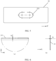
- subfigure (a) of FIG. 6 shows a local region of the bottom wall 212 of the housing 21, and subfigure (b) of FIG. 6 shows a local region of the cover plate 22.
- the bottom wall 212 of the housing 21 is perpendicular to the first direction X.
- the thickness of the bottom wall 212 along the first direction X is T2.
- the cover plate 22 is perpendicular to the first direction X.
- the thickness of the cover plate 22 along the first direction X is T1.
- the thickness T2 of the bottom wall 212 is greater than the thickness T1 of the cover plate 22.
- the relatively large thickness T2 of the bottom wall 212 ensures sufficient strength of the bottom wall 212, and enables the electrode terminal 24 to be stably fixed on the bottom wall 212.
- the relatively small thickness T1 of the cover plate 22 reduces the weight and volume of the battery cell 20, and increases the energy density of the battery cell 20.
- the bottom wall 212 of the housing 21 is configured to dispose the electrode terminal 24, if the thickness T2 of the bottom wall 212 is relatively small, then the strength of the bottom wall 212 may be deficient, and the bottom wall 212 may be unable to effectively support the electrode terminal 24. If the thickness T2 of the bottom wall 212 is relatively large, then the weight and footprint of the battery cell 20 are increased, and, when the battery cell 20 is applied "upright" in an electrical device, the pressure on the sidewall 213 of the housing 21 is increased, thereby impairing the structural stability of the battery cell 20. Therefore, the thickness T2 of the bottom wall 212 of the housing 21 needs to fall within an appropriate range.
- the thickness T2 of the bottom wall 212 of the housing 21 is greater than or equal to 0.1 mm and less than or equal to 5 mm, thereby not only ensuring sufficient strength of the bottom wall 212, but also avoiding an unnecessary increase in weight and volume, and ensuring relatively high structural stability of the battery cell 20.
- the thickness T2 of the bottom wall 212 may be approximately 1 mm.
- the cover plate 22 is opposite to the bottom wall 212. No electrode terminal 24 needs to be disposed on the cover plate 22. If the thickness T1 of the cover plate 22 is relatively large, then the large thickness increases the weight and footprint of the battery cell 20. If the thickness T1 of the cover plate 22 is relatively small, then the small thickness increases the difficulty of connection between the cover plate 22 and the housing 21. For example, during welding between the cover plate 22 and the housing 21, the small thickness increases the difficulty of the welding process. Therefore, in some embodiments, the thickness T1 of the cover plate 22 is greater than or equal to 0.1 mm and less than or equal to 3 mm, thereby reducing the weight and volume of the battery cell 20 but without increasing the difficulty of connection between the cover plate 22 and the housing 21. For example, the thickness T1 of the cover plate 22 may be 0.5 mm to 0.6 mm.
- the thickness of the sidewall 213 may remain the same as the thickness of the sidewall of the housing 21 in the related art.
- the thickness of the sidewall 213 may be greater than or equal to 0.4 mm and less than or equal to 0.5 mm.
- the thickness of the sidewall 213 may be less than or equal to the thickness T2 of the bottom wall 212, and may differ from the thickness T2 of the bottom wall 212 by a margin that falls within an appropriate range such as 0.1 mm to 2 mm, so as to avoid the damage caused by an excessive difference of the stretching amount between the sidewall and the bottom wall during stretching of the housing 21.
- the cover plate 22 is made of a metal material or a polymer material. Such materials are easily achievable and ensure sufficient strength of the cover plate 22.
- the cover plate 22 may be connected to the housing 21 by welding, riveting, bonding, snap-fitting, or the like.
- the cover plate 22 is welded to the housing 21.
- the connection implemented by welding exhibits the advantages of good connection performance, high airtightness and watertightness, and easy operation and implementation, thereby not only implementing the connection between the cover plate 22 and the housing 21, but also improving the hermeticity of the junction between the cover plate 22 and the housing 21.
- the cover plate 22 may be welded to the housing 21 by laser welding.
- Laser welding exhibits the advantages of fast speed, large depth, narrow weld seams, and resistance to deformation, and is especially suitable for a safety-demanding scenarios such as batteries, and can implement reliable welding between the housing 21 and the cover plate 22 of the battery cell 20.
- the junction between the cover plate 22 and the housing 21 may mean, for example, a region of the cover plate 22 and the housing 21, the region being used for implementing fixation and connection between the cover plate and the housing.
- the junction between the cover plate 22 and the housing 21 may be a weld mark formed by welding between the cover 22 and the housing 21.
- the following description uses an example in which the cover plate 22 is connected to the housing 21 by welding.
- a blocking structure 214 is disposed in the opening 211 of the housing 21.
- the blocking structure 214 is configured to limit a depth by which the cover plate 22 enters the housing 21 in a first direction X perpendicular to the bottom wall 212. Because the blocking structure 214 constrains the cover plate 22 in the first direction X, the cover plate 22 is not prone to wobble in the first direction X in a process of connecting the cover plate 22 to the housing 21.
- the blocking structure 214 is a ramp 214 formed on a surface of a sidewall 213 of the housing 21, the surface being oriented toward the interior of the housing 21.
- FIG. 8 that is a schematic diagram of connection between the housing 21 and the cover plate 22, the dimension L of the cover plate 22 in a second direction Y perpendicular to the sidewall 213 of the housing 21 falls between a first distance H1 and a second distance H2.
- the first distance H1 and the second distance H2 are a minimum distance and a maximum distance between two opposite ramps 214 in the second direction Y respectively.
- the ramp 214 is disposed on the surface of the sidewall 213, the surface being oriented toward the interior of the housing 21.
- Appropriate dimensions of the ramp 214 and the cover plate 22 in the second direction Y are selected. In this way, when the cover plate 22 fits and covers the opening 211 along the first direction X, the ramp 214 can limit the depth by which the cover plate 22 enters the housing 21, so that the cover plate 22 is constrained in the first direction X, and the cover plate 22 is not prone to wobble in the first direction X in a process of connecting the cover plate 22 to the housing 21. Understandably, the dimension L may be a maximum dimension of the cover plate 22 in the second direction Y.
- the dimension of a part of the cover plate 22, the part being located on a side oriented toward the interior of the battery cell 20, may be smaller than the dimension of a part of the cover plate 22, the part being located on a side oriented away from the interior of the battery cell 20.
- the blocking structure 214 is a step 214 formed on a surface of a sidewall 213 of the housing 21, the surface being oriented toward the interior of the housing 21.
- the cover plate 22 is disposed on the step 214.
- the step 214 can limit the depth by which the cover plate 22 enters the housing 21, so that the cover plate 22 is constrained in the first direction X, and the cover plate 22 is not prone to wobble in the first direction X in a process of connecting the cover plate 22 to the housing 21.
- FIG. 7 to FIG. 9 are merely examples.
- the blocking structure 214 may be in other forms different from the ramp 214 and the step 214 shown in FIG. 7 to FIG. 9 .
- the form of the blocking structure is not limited herein.
- a weld seam between the cover plate 22 and the housing 21 is perpendicular to the bottom wall 212.
- a weld mark 25 formed by welding between the cover plate 22 and the housing 21 exceeds the sidewall 213 in the first direction X by a margin W1 less than or equal to 0.5 mm.
- the weld mark 25 exceeds the sidewall 213 in the second direction Y by a margin W2 less than or equal to 0.08 mm.
- FIG. 10 and FIG. 11 are schematic diagrams of a weld mark 25 formed by welding the housing 21 and the cover plate 22 based on the structure shown in FIG. 7 to FIG. 9 . As can be seen, the weld seam between the cover plate 22 and the housing 21 runs along the first direction X.
- the cover plate 22 is welded to the housing 21 along the first direction X.
- the weld seam is a seam used for welding and formed between an end face of the cover plate 22 along the second direction Y and the sidewall 213 of the housing 21.
- the weld mark 25 formed by the welding exceeds the sidewall 213 in the first direction X by a margin W1 less than or equal to 0.5 mm, and the weld mark 25 exceeds the sidewall 213 in the second direction Y by a margin W2 less than or equal to 0.08 mm. In this way, the weld mark 25 formed by the welding between the cover plate 22 and the housing 21 can be prevented from interfering with other surrounding structural components, thereby avoiding an impact on other structural components.
- the cover plate 22 includes a first part 221 and a second part 222.
- a dimension L1 of the second part 222 in the second direction Y perpendicular to the sidewall 213 of the housing 21 is greater than a dimension L2 of the first part 221 in the second direction Y.
- the first part 221 is accommodated in the opening 211, and an edge of the second part 222 abuts on an end face of the sidewall 213, the end face being oriented away from the bottom wall 212.
- the sidewall 213 can block the second part 222 from entering the housing 21, thereby limiting the depth by which the cover plate 22 enters the housing 21.
- the cover plate 22 is constrained in the first direction X, and the cover plate 22 is not prone to wobble in the first direction X in a process of connecting the cover plate 22 to the housing 21.
- the weld seam between the cover plate 22 and the housing 21 is perpendicular to the sidewall 213.
- the weld mark 25 formed by the welding between the cover plate 22 and the housing 21 exceeds the sidewall 213 in the first direction X by a margin less than or equal to 0.5 mm, and the weld mark exceeds the sidewall 213 in the second direction Y by a margin less than or equal to 0.08 mm.
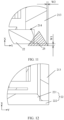
- FIG. 14 is a schematic diagram of a weld mark 25 formed by welding the housing 21 and the cover plate 22 based on the structure shown in FIG. 12 and FIG. 13 .
- the weld seam between the cover plate 22 and the housing 21 runs along the second direction Y.
- the cover plate 22 is welded to the housing 21 along the second direction Y.
- the weld seam is a seam used for welding and formed between a surface of the second part 222 and an end face, away from the bottom wall 212, of the sidewall 213, where the surface of the second part exceeds the first part 221 along the second direction Y and is oriented toward the interior of the battery cell 20.
- the weld mark 25 formed by the welding exceeds the sidewall 213 in the first direction X by a margin W1 less than or equal to 0.5 mm, and the weld mark 25 exceeds the sidewall 213 in the second direction Y by a margin W2 less than or equal to 0.08 mm. In this way, the weld mark 25 formed by the welding between the cover plate 22 and the housing 21 can be prevented from interfering with other surrounding structural components, thereby avoiding an impact on other structural components.
- An embodiment of this application further provides a battery 10.
- the battery 10 includes: the battery cell 20 according to any one of the foregoing embodiments; and a box 11, where the box 11 is configured to accommodate a plurality of battery cells 20.
- the electrode terminal 24 of the battery cell 20 is disposed on the bottom wall 212, away from the cover plate 22, of the housing 21, so that the junction between the cover plate 22 and the housing 21 is far away from the electrode terminal 24. Therefore, when the battery 10 is subjected to an external impact, the impact on the junction between the cover plate 22 and the housing 21 of the battery cell 20 is reduced, the risk of failure of connection between the cover plate 22 and the housing 21 is reduced, and the safety performance of the battery cell 10 is improved.
- the cover plate 22 of the battery cell 20 is fixed to a wall of the box 22.
- sidewalls 213 of the housings 21 of adjacent battery cells 20 in the box 11 are fixed to each other.
- the cover plate 22 of the battery cell 20 is located below the bottom wall 212 of the housing 21 of the battery cell 20 when the battery 10 is disposed in an electrical device.
- An embodiment of this application further provides an electrical device 50.
- the electrical device 50 includes the battery 10 according to any one of the foregoing embodiments.
- the battery 10 is configured to provide electrical energy for the electrical device 50.
- the electrical device 50 may be a vehicle, for example.
Landscapes
- Chemical & Material Sciences (AREA)
- Chemical Kinetics & Catalysis (AREA)
- Electrochemistry (AREA)
- General Chemical & Material Sciences (AREA)
- Inorganic Chemistry (AREA)
- Battery Mounting, Suspending (AREA)
- Connection Of Batteries Or Terminals (AREA)
- Sealing Battery Cases Or Jackets (AREA)
Abstract
Description
- This application relates to the technical field of batteries, and in particular, to a battery cell, a battery, and an electrical device.
- Energy conservation and emission reduction are key to sustainable development of the automobile industry. Based on this situation, electric vehicles have become an important part of the sustainable development of the automobile industry by virtue of energy saving and environmental friendliness. Battery technology is crucial to development of electric vehicles.
- The battery is mounted in an electrical device such as a vehicle. Because the movement of the vehicle causes some impact on the battery, the structure of a battery cell in the battery directly affects the safety of the battery. Therefore, how to improve the structure of the battery cell to enhance the safety of the battery cell has become a problem to be solved.
- This application provides a battery cell, a battery, and an electrical device, and enhances safety of the battery cell by improving the structure of the battery cell.
- According to a first aspect, a battery cell is provided. The battery cell includes: a housing, on which an opening is created; an electrode assembly, accommodated in the housing; an electrode terminal, disposed on a bottom wall of the housing and connected to a tab of the electrode assembly, where the bottom wall is opposite to the opening; and a cover plate, connected to the housing and configured to fit and cover the opening.
- The electrode terminal is disposed on the bottom wall of the housing, and the cover plate is connected to the housing and fits and covers the opening of the housing, and therefore, a junction between the cover plate and the housing is located on the opposite side of the electrode terminal, and the junction between the cover plate and the housing is relatively far away from the electrode terminal. This reduces the impact on the junction between the cover plate and the housing when the battery cell is subjected to an external impact, reduces the risk of failure of the connection between the cover plate and the housing, and improves the safety of the battery cell.
- In an implementation, the battery cell is disposed in a box of a battery, and the cover plate is fixed to a wall of the box. When the battery cells are assembled to form a battery, the cover plate of the battery cell is fixed to the wall of the box, thereby reducing the impact on the junction between the cover plate and the housing, and enhancing the safety of the battery cell.
- In an implementation, the box contains a plurality of the battery cells. Sidewalls of the housings of adjacent battery cells are fixed to each other. When the battery cells are assembled to form a battery, the adjacent battery cells are fixed to each other, thereby ensuring stability of the junction between the cover plate and the housing, and enhancing the safety of the battery cell.
- In an implementation, the cover plate is located below the bottom wall when the battery is disposed in an electrical device. When a battery is formed of the battery cells and applied in an electrical device such as a vehicle, the battery cells are positioned "upright". In this way, when a chassis of a vehicle is impacted during movement of the vehicle or when another emergency occurs, because the electrode terminals of the battery cell face upward, the above arrangement reduces the damage to the electrode terminals caused by the impact or other emergencies, and ensures safety of the battery.
- In an embodiment, a thickness of the bottom wall is greater than a thickness of the cover plate. The relatively large thickness of the bottom wall ensures sufficient strength of the bottom wall, and enables the electrode terminal to be stably fixed on the bottom wall. The relatively small thickness of the cover plate reduces the weight and volume of the battery cell, and increases the energy density of the battery cell.
- In an embodiment, a thickness of the bottom wall is greater than 0.1 mm and less than or equal to 5 mm, thereby not only ensuring sufficient strength of the bottom wall, but also avoiding an unnecessary increase in weight and volume, and ensuring relatively high structural stability of the battery cell.
- In an embodiment, a thickness of the cover plate is greater than or equal to 0.1 mm and less than or equal to 3 mm, thereby reducing the weight and volume of the battery cell but without increasing the difficulty of connection between the cover plate and the housing.
- In this embodiment, the cover plate is made of a metal material or a polymer material. Such materials are easily achievable and ensure sufficient strength of the cover plate.
- In an embodiment, the cover plate is welded to the housing. The connection implemented by welding exhibits the advantages of good connection performance, high airtightness and watertightness, and easy operation and implementation, thereby not only implementing the connection between the cover plate and the housing, but also improving the hermeticity of the junction between the cover plate and the housing.
- In an implementation, the cover plate is welded to the housing by laser welding. Laser welding exhibits the advantages of fast speed, large depth, narrow weld seams, and resistance to deformation, and is especially suitable for a safety-demanding scenarios such as batteries, and can implement reliable welding between the housing and the cover plate of the battery cell.
- In an implementation, a blocking structure is disposed in the opening of the housing. The blocking structure is configured to limit a depth by which the cover plate enters the housing in a first direction perpendicular to the bottom wall. Because the blocking structure constrains the cover plate in the first direction, the cover plate is not prone to wobble in the first direction X in a process of connecting the cover plate to the housing.
- In an implementation, the blocking structure is a ramp formed on a surface of a sidewall of the housing, the surface being oriented toward an interior of the housing. A dimension of the cover plate in a second direction perpendicular to the sidewall falls between a first distance and a second distance. The first distance and the second distance are a minimum distance and a maximum distance between two opposite ramps in the second direction respectively. In this way, when the cover plate fits and covers the opening along the first direction, the ramp can limit the depth by which the cover plate enters the housing, so that the cover plate is constrained in the first direction, and the cover plate is not prone to wobble in the first direction in a process of connecting the cover plate to the housing.
- In an implementation, the blocking structure is a step formed on a surface of a sidewall of the housing, the surface being oriented toward an interior of the housing. The cover plate is disposed on the step. In this way, when the cover plate fits and covers the opening along the first direction, because the edge of the cover plate laps the step face, the step can limit the depth by which the cover plate enters the housing, so that the cover plate is constrained in the first direction, and the cover plate is not prone to wobble in the first direction in a process of connecting the cover plate to the housing.
- In an implementation, a weld seam between the cover plate and the housing is perpendicular to the bottom wall. A weld mark formed by welding between the cover plate and the housing exceeds the sidewall in the first direction by a margin less than or equal to 0.5 mm, and the weld mark exceeds the sidewall in the second direction by a margin less than or equal to 0.08 mm. In this way, this avoids interference between the weld mark and other surrounding structural components, and avoids an impact on other structural components, where the weld mark is formed by welding between the cover plate and the housing.
- In an implementation, the cover plate includes a first part and a second part. A dimension of the second part in a second direction perpendicular to a sidewall of the housing is greater than a dimension of the first part in the second direction. The first part is accommodated in the opening. An edge of the second part abuts on an end face of the sidewall, the end face being oriented away from the bottom wall. With a T-shaped cover plate in use, when the cover plate fits and covers the opening along the first direction, because the edge of the second part of the cover plate abuts on the end face of the sidewall and the end face is oriented away from the bottom wall, the sidewall can block the second part from entering the housing, thereby limiting the depth by which the cover plate enters the housing. In this way, the cover plate is constrained in the first direction, and the cover plate is not prone to wobble in the first direction in a process of connecting the cover plate to the housing.
- In an implementation, a weld seam between the cover plate and the housing is perpendicular to the sidewall. A weld mark formed by welding between the cover plate and the housing exceeds the sidewall in the first direction by a margin less than or equal to 0.5 mm, and the weld mark exceeds the sidewall in the second direction by a margin less than or equal to 0.08 mm. In this way, this avoids interference between the weld mark and other surrounding structural components, and avoids an impact on other structural components, where the weld mark is formed by welding between the cover plate and the housing.
- In an implementation, an injection hole configured to inject an electrolyte solution is further created on the bottom wall, thereby facilitating injection of the electrolyte solution into the battery cell.
- In an implementation, an electrode lead-out hole is further created on the bottom wall. The electrode terminal is mounted in the electrode lead-out hole. The electrode lead-out hole facilitates electrical connection between a tab of the electrode assembly and the electrode terminal, so that a current of the tab can be led from the electrode lead-out hole to the electrode terminal.
- In an implementation, a pressure relief mechanism is disposed on the cover plate. The pressure relief mechanism is configured to release an internal pressure of the battery cell when the internal pressure exceeds a threshold. The electrode terminal of the battery cell is disposed on the bottom wall of the housing, and the pressure relief mechanism is disposed on the cover plate opposite to the bottom wall. In other words, the pressure relief mechanism and the electrode terminal are disposed on different walls of the battery cell. In this way, the emissions in the battery cell are farther away from the electrode terminal, thereby reducing the impact of the emissions on the electrode terminal and busbar component, and further enhancing the safety of the battery.
- According to a second aspect, a battery is provided, including: a plurality of battery cells disclosed in the first aspect or any implementation of the first aspect; and a box, configured to accommodate the plurality of the battery cells, where the cover plate of the battery cell is fixed to the wall of the box.
- In an implementation, sidewalls of the housings of adjacent battery cells in the box are fixed to each other.
- In an implementation, the cover plate of the battery cell is located below the bottom wall of the housing of the battery cell when the battery is disposed in an electrical device.
- According to a third aspect, an electrical device is provided, including the battery disclosed in the second aspect or any implementation of the second aspect. The battery is configured to provide electrical energy.
- To describe the technical solutions of some embodiments of this application more clearly, the following outlines the drawings used in the embodiments of this application. Evidently, the drawings outlined below are merely a part of embodiments of this application. A person of ordinary skill in the art may derive other drawings from the outlined drawings without making any creative efforts.
-
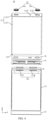
FIG. 1 is a schematic structural diagram of a vehicle according to an embodiment of this application; -
FIG. 2 is a schematic structural diagram of a battery according to an embodiment of this application; -
FIG. 3 is a schematic structural diagram of a battery cell according to an embodiment of this application; -
FIG. 4 is an exploded view of a battery cell according to an embodiment of this application; -
FIG. 5 is a schematic diagram of a pressure relief mechanism according to an embodiment of this application; -
FIG. 6 is a schematic diagram of a partial region of a bottom wall of a housing and a cover plate according to an embodiment of this application; -
FIG. 7 is a close-up view of a junction between a housing and a cover plate according to an embodiment of this application; -
FIG. 8 is a schematic diagram of connection between a housing and a cover plate according to an embodiment of this application; -
FIG. 9 is a close-up view of a junction between a housing and a cover plate according to an embodiment of this application; -
FIG. 10 andFIG. 11 are schematic diagrams of weld marks formed by welding between a housing and a cover plate based on structures shown inFIG. 7 to FIG. 9 ; -
FIG. 12 is a close-up view of a junction between a housing and a cover plate according to an embodiment of this application; -
FIG. 13 is a schematic diagram of connection between a housing and a cover plate according to an embodiment of this application; and -
FIG. 14 is a schematic diagram of a weld mark formed by welding between a housing and a cover plate based on structures shown inFIG. 12 andFIG. 13 . - The following gives a more detailed description of implementations of this application with reference to drawings and embodiments. The detailed description of the following embodiments and drawings are intended to describe the principles of this application illustratively, but not to limit the scope of this application. Therefore, this application is not limited to the described embodiments.
- In the description of this application, unless otherwise specified, "a plurality of" means at least two in number; the terms such as "up", "down", "left", "right", "in", and "out" indicating a direction or a position relationship are merely intended for ease or brevity of description of this application, but do not indicate or imply that the mentioned device or component is necessarily located in the specified direction and position or constructed or operated in the specified direction and position. Therefore, such terms are not to be understood as a limitation on this application. In addition, the terms "first", "second", "third", and so on are merely used for descriptive purposes, but not construed as indicating or implying relative importance. "Perpendicular" does not means exact perpendicularity, but means perpendicularity falling within an error tolerance range. "Parallel" does not mean exact parallelism, but means parallelism falling within an error tolerance range.
- The directional terms appearing in the following description indicate the directions shown in the drawings, but are not intended to limit specific structures in this application. In the description of this application, unless otherwise expressly specified, the terms "mount", "concatenate", and "connect" are understood in a broad sense. For example, a "connection" may be a fixed connection, a detachable connection, or an integrated connection, and may be a direct connection or an indirect connection implemented through an intermediary. A person of ordinary skill in the art can understand the specific meanings of the terms in this application according to specific situations.
- The term "and/or" in this application indicates merely a relation for describing the related items, and represents three possible relationships. For example, "A and/or B" may represent the following three circumstances: A alone, both A and B, and B alone. In addition, the character "/" herein generally indicates an "or" relationship between the item preceding the character and the item following the character.
- Unless otherwise defined, all technical and scientific terms used herein have the same meanings as what is normally understood by a person skilled in the technical field of this application. The terms used in the specification of this application are merely intended to describe specific embodiments but not intended to limit this application. The terms "include" and "contain" and any variations thereof used in the specification, claims, and brief description of drawings of this application are intended as non-exclusive inclusion. The terms such as "first" and "second" used in the specification, claims, and brief description of drawings herein are intended to distinguish between different items, but are not intended to describe a specific sequence or order of precedence.
- Reference to "embodiment" in this application means that a specific feature, structure or characteristic described with reference to the embodiment may be included in at least one embodiment of this application. Reference to this term in different places in the specification does not necessarily represent the same embodiment, nor does it represent an independent or alternative embodiment in a mutually exclusive relationship with other embodiments. A person skilled in the art explicitly and implicitly understands that an embodiment described in this application may be combined with another embodiment.
- Although this application has been described with reference to exemplary embodiments, various improvements may be made to the embodiments without departing from the scope of this application, and some components described in the embodiments may be replaced with equivalents. Particularly, to the extent that no structural conflict exists, various technical features mentioned in different embodiments may be combined in any manner. This application is not limited to the specific embodiments disclosed herein, but includes all technical solutions falling within the scope of the claims.
- In this application, a battery means a physical module that includes one or more battery cells to provide electrical energy. For example, the battery in this application may include a battery module, a battery pack, or the like. A battery typically includes a box configured to package one or more battery cells. The box prevents liquid or other foreign matters from affecting the charging or discharging of the battery cells.
- In some embodiments, a battery cell may include types such as a lithium-ion secondary battery, a lithium-ion primary battery, a lithium-sulfur battery, a sodium-lithium-ion battery, a sodium-ion battery, or a magnesium-ion battery. The type of the battery cell is not limited herein. The battery cell is also referred to as a cell.
- To meet different power demands, a plurality of battery cells in a battery may be connected in series, parallel, or series-and-parallel pattern. The series-and-parallel pattern means a combination of series connection and parallel connection. In some embodiments, the plurality of battery cells may be connected in series, parallel, or series-and-parallel pattern to form a battery module, and then a plurality of battery modules may be connected in series, parallel, or series-and-parallel pattern to form the battery. In other words, the plurality of battery cells may directly form the battery, or form the battery modules that are then used to form the battery. The battery is further mounted in the electrical device to provide electrical energy for the electrical device.
- The battery box may further include a signal transmission assembly. The signal transmission assembly may be configured to transmit signals such as voltage and/or temperature of the battery cell. The signal transmission assembly may include a busbar component. The busbar component is configured to implement electrical connection, such as parallel connection, series connection, or series-and-parallel connection, between a plurality of battery cells. The busbar component may implement electrical connection between the battery cells by connecting electrode terminals of the battery cells. In some embodiments, the busbar component may be fixed to the electrode terminals of the battery cell by welding. The busbar component transmits the voltage of the battery cell. A plurality of battery cells are connected in series to obtain a higher voltage. Correspondingly, an electrical connection formed by the busbar component may be referred to as a "high-voltage connection".
- The signal transmission assembly may further include, in addition to the busbar component, a sensor device configured to sense the status of a battery cell. For example, the sensor device may be configured to measure and transmit sensed signals such as temperature and state of charge of the battery cell.
- The busbar component and the sensor device may be packaged in an insulation layer to form the signal transmission assembly. Accordingly, the signal transmission assembly may be configured to transmit voltage and/or sensed signals of the battery cell. No insulation layer is disposed at a junction between the signal transmission assembly and the electrode terminal of the battery cell. In other words, the insulation layer is opened at the junction to enable connection to the electrode terminal of the battery cell.
- A battery cell includes an electrode assembly and an electrolytic solution. The electrode assembly includes a positive electrode plate, a negative electrode plate, and a separator. The battery cell works primarily by relying on shuttling of metal ions between the positive electrode plate and the negative electrode plate. The positive electrode plate includes a positive current collector and a positive active material layer. A surface of the positive current collector is coated with the positive active material layer. Of the current collector, a part not coated with the positive active material layer protrudes from a part coated with the positive active material layer, and the part not coated with the positive active material layer serves as a positive tab. Using a lithium-ion battery as an example, the positive current collector may be made of aluminum, and a positive active material may be lithium cobalt oxide, lithium iron phosphate, ternary lithium, lithium manganese oxide, or the like. The negative electrode plate includes a negative current collector and a negative active material layer. A surface of the negative current collector is coated with the negative active material layer. Of the current collector, a part not coated with the negative active material layer protrudes from a part coated with the negative active material layer, and the part not coated with the negative active material layer serves as a negative tab. The negative current collector may be made of copper, and a negative active material may be carbon, silicon, or the like. To prevent a large electrical current from tripping the circuit, a plurality of positive tabs are stacked together, and a plurality of negative tabs are stacked together. The separator may be made of a material such as polypropylene (polypropylene, PP) or polyethylene (polyethylene, PE). In addition, the electrode assembly may be of a jelly-roll type structure or a stacked type structure, without being limited herein.
- The battery cell further includes a housing and an end cap. The housing includes an opening. The end cap is configured to fit and cover the opening of the housing, so as to combine with the housing to form an accommodation space. The accommodation space is configured to accommodate the electrode assembly and an electrolyte solution. During assembling, the electrode assembly may be mounted into the housing through the opening of the housing, and then the end cap is connected to the housing to seal the opening of the housing.
- To lead out the electrical energy from the electrode assembly, the battery cell is usually further fitted with an electrode terminal. The electrode terminal is configured to electrically connect the electrode assembly to an external circuit to implement charging and discharging of the electrode assembly.
- In a battery, the electrode terminal needs to be connected to external components such as a busbar component and a detection harness. When a battery cell is subjected to an external impact, the external components pull the electrode terminal. In the related art, the electrode terminal is usually mounted on the end cap. When an external component exerts a pushing or pulling force or a twisting force on the electrode terminal, the force is applied to the junction between the end cap and the housing accordingly. The long-term fatigue stress at the junction between the end cap and the housing may eventually result in a crack, cause failure of the connection between the end cap and the housing, give rise to risks such as electrolyte leakage or even fire, and pose safety hazards.
- In view of this, this application provides a technical solution. In this technical solution, the end cap is replaced with a cover plate. The cover plate is configured to fit and cover the opening of the housing. By disposing the electrode terminal at one end of the housing away from the cover plate, the junction between the cover plate and the housing is far away from the electrode terminal. Therefore, when the battery cell is subjected to an external impact, the impact on the junction between the cover plate and the housing is reduced, the risk of failure of connection between the cover plate and the housing is reduced, and the safety of the battery cell is improved.
- All technical solutions described in the embodiments of this application are applicable to various battery-powered devices such as a mobile phone, a portable device, a laptop computer, an electric power cart, an electrical toy, an electric tool, an electric vehicle, a ship, and a spacecraft. The spacecraft includes an airplane, a rocket, a space shuttle, a spaceship, and the like. The vehicle may be an oil-fueled vehicle, a natural gas vehicle, or a new energy vehicle. The new energy vehicle may be a battery electric vehicle, a hybrid electric vehicle, a range-extended electric vehicle, or the like. The spacecraft includes an airplane, a rocket, a space shuttle, a spaceship, and the like. The electric toy includes a fixed or mobile electric toy, such as a game console, an electric car toy, an electric ship toy, an electric airplane toy, and the like. The power tool includes an electrical metal cutting tool, an electrical grinding tool, an electrical assembling tool, and a power tool for use in railways. Examples of the power tool are an electrical drill, an electrical grinder, an electrical wrench, an electrical screwdriver, an electrical hammer, an electrical impact drill, a concrete vibrator, an electrical planer, and the like. The electrical device is not particularly limited in embodiments of this application.
- Understandably, the technical solutions described in the embodiments of this application are not only applicable to the devices mentioned above, but also applicable to all battery-powered devices. However, for brevity, the following embodiments are described by using a vehicle as an example.
- For example, as shown in
FIG. 1 , which is a schematic structural diagram of avehicle 1 according to an embodiment of this application, thevehicle 1 may be an oil-fueled vehicle, a natural gas vehicle, or a new energy vehicle. The new energy vehicle may be a battery electric vehicle, a hybrid electric vehicle, a range-extended electric vehicle, or the like. Amotor 40, acontroller 30, and abattery 10 may be disposed inside thevehicle 1. Thecontroller 30 is configured to control thebattery 10 to supply power to themotor 40. For example, thebattery 10 may be disposed at the bottom, front, or rear of thevehicle 1. Thebattery 10 may be configured to supply power to thevehicle 1. For example, thebattery 10 may serve as an operating power supply of thevehicle 1 to power a circuit system of thevehicle 1. For example, the battery may be configured to meet operating power usage requirements of thevehicle 1 that is being started or navigated or running. In another embodiment of this application, thebattery 10 serves not only as an operating power supply of thevehicle 1, but may also serve as a driving power supply of thevehicle 1 to provide driving power for thevehicle 1 in place of or partly in place of fuel oil or natural gas. - The
battery 10 may include a plurality of battery cells. For example, as shown inFIG. 2 , which is a schematic structural diagram of abattery 10 according to an embodiment of this application, thebattery 10 may include a plurality ofbattery cells 20. Thebattery 10 may further include abox 11. The interior of thebox 11 is a hollow structure. A plurality ofbattery cells 20 are accommodated in thebox 11. As shown inFIG. 2 , thebox 11 may include two parts, herein referred to as afirst box portion 111 and asecond box portion 112 respectively. Thefirst box portion 111 and thesecond box portion 112 are snap-fitted together. The shapes of thefirst box portion 111 and thesecond box portion 112 may depend on the shape of the plurality ofbattery cells 20 combined. An opening is created on at least one of thefirst box portion 111 or thesecond box portion 112. For example, as shown inFIG. 2 , both thefirst box portion 111 and thesecond box portion 112 each may be a hollow cuboid, and each may include only one opening surface. The opening of thefirst box portion 111 is opposite to the opening of thesecond box portion 112. Thefirst box portion 111 and thesecond box portion 112 are snap-fitted together to form abox 11 that includes a closed cavity. For another example, different from what is shown inFIG. 2 , of thefirst box portion 111 and thesecond box portion 112, only one is a hollow cuboid with an opening, and the other assumes a plate shape to cover the opening. For example, thesecond box portion 112 is a hollow cuboid with only one opening surface, and thefirst box portion 111 assumes a plate shape. In this case, thefirst box portion 111 fits and covers the opening of thesecond box portion 112 to form a box with a closed cavity. The cavity may be configured to accommodate a plurality ofbattery cells 20. The plurality ofbattery cells 20 are connected in parallel, series, or series-and-parallel pattern and combined together, and then placed into thebox 11 that is formed by snap-fitting thefirst box portion 111 and thesecond box portion 112. Definitely, thefirst box portion 111 and thesecond box portion 112 may be in other shapes such as a cylinder or a hexagonal prism. - In some embodiments, the
battery 10 may further include a busbar component (not shown in the drawing). The busbar component is configured to implement electrical connection, such as parallel, series, or series-and-parallel connection, between a plurality ofbattery cells 20. Specifically, the busbar component may implement the electrical connection between thebattery cells 20 by connecting electrode terminals of thebattery cells 20. Further, the busbar component may be fixed to the electrode terminals of thebattery cells 20 by welding. Electrical energy of the plurality ofbattery cells 20 may be further led out by a conductive mechanism running through thebox 11. In some embodiments, the conductive mechanism may belong to the busbar component. - Further, the
battery 10 may include other structures, which are not enumerated exhaustively here.FIG. 2 uses 6battery cells 20 as an example. In practical applications, depending on the required power, the number ofbattery cells 20 in abattery 10 may be set to any other value. Thebattery cells 20 may be connected in series, parallel, or series-and-parallel pattern to achieve a relatively high capacity or power. -
FIG. 3 is a schematic structural diagram of abattery cell 20 according to an embodiment of this application. As shown inFIG. 3 , thebattery cell 20 includes ahousing 21, acover plate 22, anelectrode assembly 23, and anelectrode terminal 24. Thehousing 21 includes anopening 211. Theelectrode assembly 23 is accommodated in thehousing 21. Thecover plate 22 is connected to thehousing 21, and is configured to fit and cover theopening 211. Theelectrode terminal 24 of thebattery cell 20 is disposed on thebottom wall 212 of thehousing 21 and connected to a tab 231 (not shown in the drawing) of theelectrode assembly 23. Thebottom wall 212 is opposite to theopening 211. - The
electrode terminal 24 is disposed on thebottom wall 212 of thehousing 21, and thecover plate 22 is connected to thehousing 21 and fits and covers theopening 211 of thehousing 21, and therefore, a junction between thecover plate 22 and thehousing 21 is located on the opposite side of theelectrode terminal 24, and the junction between thecover plate 22 and thehousing 21 is relatively far away from theelectrode terminal 24. This reduces the impact on the junction between thecover plate 22 and thehousing 21 when thebattery cell 20 is subjected to an external impact, reduces the risk of failure of the connection between thecover plate 22 and thehousing 21, and improves the safety of thebattery cell 20. - The
housing 21 is a structure hollowed out to form a space configured to accommodate theelectrode assembly 23. Theelectrode terminal 24 of thebattery cell 20 is disposed protrusively on thebottom wall 212 of thehousing 21 by protruding away from theelectrode assembly 23. Thehousing 21 may be in various shapes and sizes, such as a cuboid, cylinder, or hexagonal prism. The number ofelectrode assemblies 23 may be one or more. The shape of thehousing 21 depends on the combined shape of one ormore electrode assemblies 23. For example, if theelectrode assembly 23 is a cylindrical structure, thehousing 21 may be a cylindrical housing; or, if theelectrode assembly 23 is a cuboidal structure, thehousing 21 may be a cuboidal housing. The shape of thecover plate 22 mates with the shape of thehousing 21. For example, if thehousing 21 is a cuboidal structure, thecover plate 22 may be rectangular; if thehousing 21 is a cylindrical structure, thecover plate 22 may be circular. Both the wall of thehousing 21 and thecover plate 22 may be referred to as walls of thebattery cell 20. For acuboidal battery cell 20, as shown inFIG. 3 , the walls of thehousing 21 include abottom wall 212 and foursidewalls 213. - In some embodiments, the
battery cell 20 is disposed in abox 11 of abattery 10, and thecover plate 22 is fixed to a wall of thebox 11. Here, the wall of the box means a wall configured to be fixed to thebattery cell 20 in thebox 11. For example, the wall may be the bottom wall of thefirst box portion 111 or the bottom wall of thesecond box portion 112 shown inFIG. 2 . For another example, when one of thefirst box portion 111 or thesecond box portion 112 is plate-shaped, the plate-shaped box portion may be used as the box wall to be fixed to thebattery cell 20. Thecover plate 22 of thebattery cell 20 may be fixed to the wall of thebox 11 by means such as adhesive bonding. - When the
battery cells 20 are assembled to form abattery 10, thecover plate 22 of thebattery cell 20 is fixed to the wall of thebox 11, and theelectrode terminal 24 is located on the bottom wall of thehousing 21 and away from the wall of thebox 11. Therefore, when an external component pulls theelectrode terminal 24 and gives rise to a displacement of thehousing 21, thebattery cells 20 in thebox 11 constrain each other, thereby limiting the displacement of thehousing 21, and in turn, reducing the impact on the junction between thecover plate 22 and thehousing 21, and enhancing the safety of thebattery cell 20. - In some embodiments, the
box 11 contains a plurality of thebattery cells 20.Sidewalls 213 of thehousings 21 ofadjacent battery cells 20 are fixed to each other. Theadjacent battery cells 20 may be fixed to each other by means such as adhesive bonding. When thebattery cells 20 are assembled to form abattery 10, not only thecover plate 22 of thebattery cell 20 is fixed to the wall of thebox 11, but also thesidewalls 213 of theadjacent battery cells 20 are fixed to each other, so that thebattery cells 20 constrain each other more strongly. When an external component pulls theelectrode terminal 24 and gives rise to a displacement of thehousing 21, the displacement of thehousing 21 can be limited more effectively, thereby ensuring stability of the junction between thecover plate 22 and thehousing 21, and enhancing the safety of thebattery cell 20. - In some embodiments, when the
battery 10 is mounted in an electrical device, thecover plate 22 is located below thebottom wall 212 of thehousing 21. In other words, thebattery cell 20 is applied "upright" in the electrical device with theelectrode terminal 24 facing upward. For example, as shown inFIG. 3 andFIG. 4 . when abattery 10 is formed of thebattery cells 20 and applied in an electrical device such as avehicle 1, thebattery cells 20 are positioned "upright". In this way, when the chassis of thevehicle 1 is impacted during movement of the vehicle or when another emergency occurs, because theelectrode terminals 24 of thebattery cell 20 face upward, the above arrangement reduces the damage to theelectrode terminals 24 caused by the impact or other emergencies, and ensures safety of thebattery 10. -
FIG. 4 is an exploded view of abattery cell 20. Thehousing 21 may be molded by a stretching process, for example. As shown inFIG. 4 , thehousing 21 includes abottom wall 212 and asidewall 213. Anopening 211 is created on thehousing 21 at one end opposite to thebottom wall 212. Thecover plate 22 is configured to fit and cover theopening 211 and be connected to thehousing 21. Theelectrode assembly 23 is electrically connected to theelectrode terminal 24 by a connectingcomponent 25. One ormore electrode assemblies 23 may be accommodated in thehousing 21. As an example, twoelectrode assemblies 23 are shown inFIG. 4 . Eachelectrode assembly 23 includes atab 231. For example, the tab includes a positive tab 231a and a negative tab 231b. Theelectrode terminal 24 includes apositive electrode terminal 24a and anegative electrode terminal 24b. The positive tab 231a is connected to thepositive electrode terminal 24 by the connectingcomponent 25. The negative tab 231b is connected to thenegative electrode terminal 24b by the connectingcomponent 25.FIG. 4 further shows aninsulation component 26 disposed between the connectingcomponent 25 and thebottom wall 212, and aninsulation spacer 27 disposed around theelectrode assembly 23. Such insulating members serve a function of dielectrical isolation between theelectrode assembly 23 and thehousing 21. Theinsulation component 26 is also referred to as a lowerplastic sheet 26. In an embodiment of this application, thepositive electrode terminal 24a and thenegative electrode terminal 24b may be disposed on thebottom wall 212 concurrently. - In some embodiments, as shown in
FIG. 4 , an electrode lead-out hole 2121 is further created on thebottom wall 212. Theelectrode terminal 24 is mounted in the electrode lead-out hole 2121. The electrode lead-out hole 2121 facilitates electrical connection between thetab 231 of theelectrode assembly 23 and theelectrode terminal 24, so that the current of thetab 231 can be led from the electrode lead-out hole 2121 to theelectrode terminal 24. Theelectrode terminal 24 may be electrically connected to thetab 231 by welding, bonding, snap-fitting, pressure contact, or other means. - In some embodiments, as shown in
FIG. 4 , aninjection hole 2122 configured to inject an electrolyte solution is further created on thebottom wall 212, thereby facilitating injection of the electrolyte solution into thebattery cell 20. - In some embodiments, a
pressure relief mechanism 223 is disposed on thecover plate 22. Thepressure relief mechanism 223 is configured to release an internal pressure of thebattery cell 20 when the internal pressure exceeds a threshold. For example, as shown inFIG. 5 , thepressure relief mechanism 223 may be an explosion-proof nick created on thecover plate 22. When a short circuit, overcharge, or another phenomenon occurs, thermal runaway may occur inside thebattery cell 20 and generate a high-temperature and high-pressure gas, thereby breaking the explosion-proof nick to release the internal heat and gas pressure outward to prevent thebattery cell 20 from exploding or catching fire. - In these embodiments, the
electrode terminal 24 of thebattery cell 20 is disposed on thebottom wall 212 of thehousing 21, and thepressure relief mechanism 223 is disposed on thecover plate 22 opposite to thebottom wall 212. In other words, thepressure relief mechanism 223 and theelectrode terminal 24 are disposed on different walls of thebattery cell 20. In this way, the emissions in thebattery cell 20 are farther away from theelectrode terminal 24, thereby reducing the impact of the emissions on theelectrode terminal 24 and busbar component, and further enhancing the safety of thebattery 10. - The
electrode terminal 24 is disposed on thebottom wall 212 of thehousing 21, thecover plate 22 is opposite to thebottom wall 212, and noelectrode terminal 24 needs to be disposed on thecover plate 22. Therefore, in some embodiments, the thickness T2 of thebottom wall 212 of thehousing 21 may be greater than the thickness T1 of thecover plate 22. - For example, subfigure (a) of
FIG. 6 shows a local region of thebottom wall 212 of thehousing 21, and subfigure (b) ofFIG. 6 shows a local region of thecover plate 22. Thebottom wall 212 of thehousing 21 is perpendicular to the first direction X. The thickness of thebottom wall 212 along the first direction X is T2. Thecover plate 22 is perpendicular to the first direction X. The thickness of thecover plate 22 along the first direction X is T1. The thickness T2 of thebottom wall 212 is greater than the thickness T1 of thecover plate 22. The relatively large thickness T2 of thebottom wall 212 ensures sufficient strength of thebottom wall 212, and enables theelectrode terminal 24 to be stably fixed on thebottom wall 212. The relatively small thickness T1 of thecover plate 22 reduces the weight and volume of thebattery cell 20, and increases the energy density of thebattery cell 20. - Because the
bottom wall 212 of thehousing 21 is configured to dispose theelectrode terminal 24, if the thickness T2 of thebottom wall 212 is relatively small, then the strength of thebottom wall 212 may be deficient, and thebottom wall 212 may be unable to effectively support theelectrode terminal 24. If the thickness T2 of thebottom wall 212 is relatively large, then the weight and footprint of thebattery cell 20 are increased, and, when thebattery cell 20 is applied "upright" in an electrical device, the pressure on thesidewall 213 of thehousing 21 is increased, thereby impairing the structural stability of thebattery cell 20. Therefore, the thickness T2 of thebottom wall 212 of thehousing 21 needs to fall within an appropriate range. In some embodiments, the thickness T2 of thebottom wall 212 of thehousing 21 is greater than or equal to 0.1 mm and less than or equal to 5 mm, thereby not only ensuring sufficient strength of thebottom wall 212, but also avoiding an unnecessary increase in weight and volume, and ensuring relatively high structural stability of thebattery cell 20. For example, the thickness T2 of thebottom wall 212 may be approximately 1 mm. - The
cover plate 22 is opposite to thebottom wall 212. Noelectrode terminal 24 needs to be disposed on thecover plate 22. If the thickness T1 of thecover plate 22 is relatively large, then the large thickness increases the weight and footprint of thebattery cell 20. If the thickness T1 of thecover plate 22 is relatively small, then the small thickness increases the difficulty of connection between thecover plate 22 and thehousing 21. For example, during welding between thecover plate 22 and thehousing 21, the small thickness increases the difficulty of the welding process. Therefore, in some embodiments, the thickness T1 of thecover plate 22 is greater than or equal to 0.1 mm and less than or equal to 3 mm, thereby reducing the weight and volume of thebattery cell 20 but without increasing the difficulty of connection between thecover plate 22 and thehousing 21. For example, the thickness T1 of thecover plate 22 may be 0.5 mm to 0.6 mm. - This application does not limit the thickness of the
sidewall 213 of thehousing 21. The thickness of thesidewall 213 may remain the same as the thickness of the sidewall of thehousing 21 in the related art. For example, the thickness of thesidewall 213 may be greater than or equal to 0.4 mm and less than or equal to 0.5 mm. Preferably, the thickness of thesidewall 213 may be less than or equal to the thickness T2 of thebottom wall 212, and may differ from the thickness T2 of thebottom wall 212 by a margin that falls within an appropriate range such as 0.1 mm to 2 mm, so as to avoid the damage caused by an excessive difference of the stretching amount between the sidewall and the bottom wall during stretching of thehousing 21. - In some embodiments, the
cover plate 22 is made of a metal material or a polymer material. Such materials are easily achievable and ensure sufficient strength of thecover plate 22. - The
cover plate 22 may be connected to thehousing 21 by welding, riveting, bonding, snap-fitting, or the like. Preferably, in some embodiments, thecover plate 22 is welded to thehousing 21. The connection implemented by welding exhibits the advantages of good connection performance, high airtightness and watertightness, and easy operation and implementation, thereby not only implementing the connection between thecover plate 22 and thehousing 21, but also improving the hermeticity of the junction between thecover plate 22 and thehousing 21. For example, thecover plate 22 may be welded to thehousing 21 by laser welding. Laser welding exhibits the advantages of fast speed, large depth, narrow weld seams, and resistance to deformation, and is especially suitable for a safety-demanding scenarios such as batteries, and can implement reliable welding between thehousing 21 and thecover plate 22 of thebattery cell 20. The junction between thecover plate 22 and thehousing 21 may mean, for example, a region of thecover plate 22 and thehousing 21, the region being used for implementing fixation and connection between the cover plate and the housing. For example, in a process of welding thecover plate 22 to thehousing 21, the junction between thecover plate 22 and thehousing 21 may be a weld mark formed by welding between thecover 22 and thehousing 21. The following description uses an example in which thecover plate 22 is connected to thehousing 21 by welding. - In some embodiments, a blocking
structure 214 is disposed in theopening 211 of thehousing 21. The blockingstructure 214 is configured to limit a depth by which thecover plate 22 enters thehousing 21 in a first direction X perpendicular to thebottom wall 212. Because the blockingstructure 214 constrains thecover plate 22 in the first direction X, thecover plate 22 is not prone to wobble in the first direction X in a process of connecting thecover plate 22 to thehousing 21. - For example, as shown in
FIG. 7 that is a close-up view of a junction between thehousing 21 and thecover plate 22, the blockingstructure 214 is aramp 214 formed on a surface of asidewall 213 of thehousing 21, the surface being oriented toward the interior of thehousing 21. Specifically, as shown inFIG. 8 that is a schematic diagram of connection between thehousing 21 and thecover plate 22, the dimension L of thecover plate 22 in a second direction Y perpendicular to thesidewall 213 of thehousing 21 falls between a first distance H1 and a second distance H2. The first distance H1 and the second distance H2 are a minimum distance and a maximum distance between twoopposite ramps 214 in the second direction Y respectively. As can be seen fromFIG. 8 , theramp 214 is disposed on the surface of thesidewall 213, the surface being oriented toward the interior of thehousing 21. Appropriate dimensions of theramp 214 and thecover plate 22 in the second direction Y are selected. In this way, when thecover plate 22 fits and covers theopening 211 along the first direction X, theramp 214 can limit the depth by which thecover plate 22 enters thehousing 21, so that thecover plate 22 is constrained in the first direction X, and thecover plate 22 is not prone to wobble in the first direction X in a process of connecting thecover plate 22 to thehousing 21. Understandably, the dimension L may be a maximum dimension of thecover plate 22 in the second direction Y. Optionally, in order to facilitate the entry of thecover plate 22 into thehousing 21, the dimension of a part of thecover plate 22, the part being located on a side oriented toward the interior of thebattery cell 20, may be smaller than the dimension of a part of thecover plate 22, the part being located on a side oriented away from the interior of thebattery cell 20. - For another example, as shown in
FIG. 9 that is a close-up view of a junction between thehousing 21 and thecover plate 22, the blockingstructure 214 is astep 214 formed on a surface of asidewall 213 of thehousing 21, the surface being oriented toward the interior of thehousing 21. Thecover plate 22 is disposed on thestep 214. In this way, when thecover plate 22 fits and covers theopening 211 along the first direction X, because the edge of thecover plate 22 laps the step face of thestep 214, thestep 214 can limit the depth by which thecover plate 22 enters thehousing 21, so that thecover plate 22 is constrained in the first direction X, and thecover plate 22 is not prone to wobble in the first direction X in a process of connecting thecover plate 22 to thehousing 21. -
FIG. 7 to FIG. 9 are merely examples. The blockingstructure 214 may be in other forms different from theramp 214 and thestep 214 shown inFIG. 7 to FIG. 9 . The form of the blocking structure is not limited herein. - In some embodiments, a weld seam between the
cover plate 22 and thehousing 21 is perpendicular to thebottom wall 212. Aweld mark 25 formed by welding between thecover plate 22 and thehousing 21 exceeds thesidewall 213 in the first direction X by a margin W1 less than or equal to 0.5 mm. Theweld mark 25 exceeds thesidewall 213 in the second direction Y by a margin W2 less than or equal to 0.08 mm. For example,FIG. 10 andFIG. 11 are schematic diagrams of aweld mark 25 formed by welding thehousing 21 and thecover plate 22 based on the structure shown inFIG. 7 to FIG. 9 . As can be seen, the weld seam between thecover plate 22 and thehousing 21 runs along the first direction X. In other words, thecover plate 22 is welded to thehousing 21 along the first direction X. The weld seam is a seam used for welding and formed between an end face of thecover plate 22 along the second direction Y and thesidewall 213 of thehousing 21. Theweld mark 25 formed by the welding exceeds thesidewall 213 in the first direction X by a margin W1 less than or equal to 0.5 mm, and theweld mark 25 exceeds thesidewall 213 in the second direction Y by a margin W2 less than or equal to 0.08 mm. In this way, theweld mark 25 formed by the welding between thecover plate 22 and thehousing 21 can be prevented from interfering with other surrounding structural components, thereby avoiding an impact on other structural components. - In some embodiments, as shown in
FIG. 12 that is a close-up view of a junction between thehousing 21 and thecover plate 22, thecover plate 22 includes afirst part 221 and asecond part 222. Specifically, as shown inFIG. 13 that is a schematic diagram of the connection between thehousing 21 and thecover plate 22, a dimension L1 of thesecond part 222 in the second direction Y perpendicular to thesidewall 213 of thehousing 21 is greater than a dimension L2 of thefirst part 221 in the second direction Y. In this way, thefirst part 221 is accommodated in theopening 211, and an edge of thesecond part 222 abuts on an end face of thesidewall 213, the end face being oriented away from thebottom wall 212. In this way, with a T-shapedcover plate 22 in use, when thecover plate 22 fits and covers theopening 211 along the first direction X, because the edge of thesecond part 222 of thecover plate 22 abuts on the end face of thesidewall 213 and the end face is oriented away from thebottom wall 212, thesidewall 213 can block thesecond part 222 from entering thehousing 21, thereby limiting the depth by which thecover plate 22 enters thehousing 21. In this way, thecover plate 22 is constrained in the first direction X, and thecover plate 22 is not prone to wobble in the first direction X in a process of connecting thecover plate 22 to thehousing 21. - In some embodiments, the weld seam between the
cover plate 22 and thehousing 21 is perpendicular to thesidewall 213. In other words, along the second direction Y, theweld mark 25 formed by the welding between thecover plate 22 and thehousing 21 exceeds thesidewall 213 in the first direction X by a margin less than or equal to 0.5 mm, and the weld mark exceeds thesidewall 213 in the second direction Y by a margin less than or equal to 0.08 mm. For example,FIG. 14 is a schematic diagram of aweld mark 25 formed by welding thehousing 21 and thecover plate 22 based on the structure shown inFIG. 12 andFIG. 13 . As can be seen, the weld seam between thecover plate 22 and thehousing 21 runs along the second direction Y. In other words, thecover plate 22 is welded to thehousing 21 along the second direction Y. The weld seam is a seam used for welding and formed between a surface of thesecond part 222 and an end face, away from thebottom wall 212, of thesidewall 213, where the surface of the second part exceeds thefirst part 221 along the second direction Y and is oriented toward the interior of thebattery cell 20. Theweld mark 25 formed by the welding exceeds thesidewall 213 in the first direction X by a margin W1 less than or equal to 0.5 mm, and theweld mark 25 exceeds thesidewall 213 in the second direction Y by a margin W2 less than or equal to 0.08 mm. In this way, theweld mark 25 formed by the welding between thecover plate 22 and thehousing 21 can be prevented from interfering with other surrounding structural components, thereby avoiding an impact on other structural components. - An embodiment of this application further provides a
battery 10. Thebattery 10 includes: thebattery cell 20 according to any one of the foregoing embodiments; and abox 11, where thebox 11 is configured to accommodate a plurality ofbattery cells 20. Theelectrode terminal 24 of thebattery cell 20 is disposed on thebottom wall 212, away from thecover plate 22, of thehousing 21, so that the junction between thecover plate 22 and thehousing 21 is far away from theelectrode terminal 24. Therefore, when thebattery 10 is subjected to an external impact, the impact on the junction between thecover plate 22 and thehousing 21 of thebattery cell 20 is reduced, the risk of failure of connection between thecover plate 22 and thehousing 21 is reduced, and the safety performance of thebattery cell 10 is improved. - In an implementation, when the
battery cell 20 is disposed in abox 11, thecover plate 22 of thebattery cell 20 is fixed to a wall of thebox 22. - In an implementation, sidewalls 213 of the
housings 21 ofadjacent battery cells 20 in thebox 11 are fixed to each other. - In an implementation, the
cover plate 22 of thebattery cell 20 is located below thebottom wall 212 of thehousing 21 of thebattery cell 20 when thebattery 10 is disposed in an electrical device. - Understandably, for the description about each feature of the
battery 10, reference may be made to the foregoing description about thebattery cell 20. For brevity, details are omitted here. - An embodiment of this application further provides an electrical device 50. The electrical device 50 includes the
battery 10 according to any one of the foregoing embodiments. Thebattery 10 is configured to provide electrical energy for the electrical device 50. The electrical device 50 may be a vehicle, for example. - It is hereby noted that to the extent that no conflict occurs, embodiments of this application and the features in the embodiments may be combined with each other.
- Although this application has been described with reference to exemplary embodiments, various improvements may be made to the embodiments without departing from the scope of this application, and some components described in the embodiments may be replaced with equivalents. Particularly, to the extent that no structural conflict exists, various technical features mentioned in different embodiments may be combined in any manner. This application is not limited to the specific embodiments disclosed herein, but includes all technical solutions falling within the scope of the claims.
Claims (22)
- A battery cell, characterized in that the battery cell comprises:a housing, on which an opening is created;an electrode assembly, accommodated in the housing;an electrode terminal, disposed on a bottom wall of the housing and connected to a tab of the electrode assembly, wherein the bottom wall is opposite to the opening; anda cover plate, connected to the housing and configured to fit and cover the opening, wherein the battery cell is disposed in a box of a battery, and the cover plate is fixed to a wall of the box.
- The battery cell according to claim 1, characterized in that the box contains a plurality of the battery cells, and sidewalls of the housings of adjacent battery cells are fixed to each other.
- The battery cell according to claim 1 or 2, characterized in that the cover plate is located below the bottom wall when the battery is disposed in an electrical device.
- The battery cell according to any one of claims 1 to 3, characterized in that a thickness of the bottom wall is greater than a thickness of the cover plate.
- The battery cell according to any one of claims 1 to 4, characterized in that a thickness of the bottom wall is greater than or equal to 0.1 mm and less than or equal to 5 mm.
- The battery cell according to any one of claims 1 to 5, characterized in that a thickness of the cover plate is greater than or equal to 0.1 mm and less than or equal to 3 mm.
- The battery cell according to any one of claims 1 to 6, characterized in that the cover plate is made of a metal material or a polymer material.
- The battery cell according to any one of claims 1 to 7, characterized in that the cover plate is welded to the housing.
- The battery cell according to claim 8, characterized in that the cover plate is welded to the housing by laser welding.
- The battery cell according to any one of claims 1 to 9, characterized in that a blocking structure is disposed in the opening of the housing, and the blocking structure is configured to limit a depth by which the cover plate enters the housing in a first direction perpendicular to the bottom wall.
- The battery cell according to claim 10, characterized in that the blocking structure is a ramp formed on a surface of a sidewall of the housing, the surface being oriented toward an interior of the housing; a dimension of the cover plate in a second direction perpendicular to the sidewall falls between a first distance and a second distance, and the first distance and the second distance are a minimum distance and a maximum distance between two opposite ramps in the second direction respectively.
- The battery cell according to claim 10, characterized in that the blocking structure is a step formed on a surface of a sidewall of the housing, the surface being oriented toward an interior of the housing; and the cover plate is disposed on the step.
- The battery cell according to claim 11 or 12, characterized in that a weld seam between the cover plate and the housing is perpendicular to the bottom wall, a weld mark formed by welding between the cover plate and the housing exceeds the sidewall in the first direction by a margin less than or equal to 0.5 mm, and the weld mark exceeds the sidewall in the second direction by a margin less than or equal to 0.08 mm.
- The battery cell according to any one of claims 1 to 9, characterized in that the cover plate comprises a first part and a second part, a dimension of the second part in a second direction perpendicular to a sidewall of the housing is greater than a dimension of the first part in the second direction, the first part is accommodated in the opening, and an edge of the second part abuts on an end face of the sidewall, the end face being oriented away from the bottom wall.
- The battery cell according to claim 14, characterized in that a weld seam between the cover plate and the housing is perpendicular to the sidewall, a weld mark formed by welding between the cover plate and the housing exceeds the sidewall in the first direction by a margin less than or equal to 0.5 mm, and the weld mark exceeds the sidewall in the second direction by a margin less than or equal to 0.08 mm.
- The battery cell according to any one of claims 1 to 15, characterized in that an injection hole configured to inject an electrolyte solution is further created on the bottom wall.
- The battery cell according to any one of claims 1 to 16, characterized in that an electrode lead-out hole is further created on the bottom wall, and the electrode terminal is mounted in the electrode lead-out hole.
- The battery cell according to any one of claims 1 to 17, characterized in that a pressure relief mechanism is disposed on the cover plate, and the pressure relief mechanism is configured to release an internal pressure of the battery cell when the internal pressure exceeds a threshold.
- A battery, characterized in that the battery comprises:a plurality of the battery cells according to any one of claims 1 to 18; anda box, configured to accommodate the plurality of the battery cells, wherein the cover plate of the battery cell is fixed to the wall of the box.
- The battery according to claim 19, characterized in that sidewalls of the housings of adjacent battery cells in the box are fixed to each other.
- The battery according to claim 19 or 20, characterized in that the cover plate of the battery cell is located below the bottom wall of the housing of the battery cell when the battery is disposed in an electrical device.
- An electrical device, characterized in that the electrical device comprises the battery according to any one of claims 19 to 21, and the battery is configured to provide electrical energy.
Applications Claiming Priority (1)
| Application Number | Priority Date | Filing Date | Title |
|---|---|---|---|
| PCT/CN2022/129481 WO2024092607A1 (en) | 2022-11-03 | 2022-11-03 | Battery cell, battery, and electrical device |
Publications (2)
| Publication Number | Publication Date |
|---|---|
| EP4510326A1 true EP4510326A1 (en) | 2025-02-19 |
| EP4510326A4 EP4510326A4 (en) | 2025-07-02 |
Family
ID=90929255
Family Applications (1)
| Application Number | Title | Priority Date | Filing Date |
|---|---|---|---|
| EP22963918.2A Pending EP4510326A4 (en) | 2022-11-03 | 2022-11-03 | BATTERY CELL, BATTERY AND ELECTRICAL DEVICE |
Country Status (4)
| Country | Link |
|---|---|
| US (1) | US20250070333A1 (en) |
| EP (1) | EP4510326A4 (en) |
| CN (1) | CN118830120A (en) |
| WO (1) | WO2024092607A1 (en) |
Family Cites Families (8)
| Publication number | Priority date | Publication date | Assignee | Title |
|---|---|---|---|---|
| KR101776885B1 (en) * | 2014-09-25 | 2017-09-08 | 주식회사 엘지화학 | Prismatic Battery Cell Having Two or More Case Members |
| CN111384336B (en) * | 2018-12-30 | 2024-10-18 | 宁德时代新能源科技股份有限公司 | Battery module, battery pack and vehicle |
| CN215496872U (en) * | 2021-07-30 | 2022-01-11 | 宁德时代新能源科技股份有限公司 | Battery monomer, battery and consumer |
| CN216213942U (en) * | 2021-09-30 | 2022-04-05 | 宁德时代新能源科技股份有限公司 | Battery cell, battery and power consumption device |
| CN216085065U (en) * | 2021-09-30 | 2022-03-18 | 宁德时代新能源科技股份有限公司 | Battery cell, battery and power consumption device |
| CN216085200U (en) * | 2021-09-30 | 2022-03-18 | 宁德时代新能源科技股份有限公司 | Battery cell, battery and power consumption device |
| CN216354676U (en) * | 2021-10-20 | 2022-04-19 | 宁德时代新能源科技股份有限公司 | Battery cell |
| CN216872137U (en) * | 2022-02-25 | 2022-07-01 | 宁德时代新能源科技股份有限公司 | Battery and electric equipment |
-
2022
- 2022-11-03 EP EP22963918.2A patent/EP4510326A4/en active Pending
- 2022-11-03 WO PCT/CN2022/129481 patent/WO2024092607A1/en not_active Ceased
- 2022-11-03 CN CN202280093083.6A patent/CN118830120A/en active Pending
-
2024
- 2024-11-14 US US18/948,377 patent/US20250070333A1/en active Pending
Also Published As
| Publication number | Publication date |
|---|---|
| WO2024092607A1 (en) | 2024-05-10 |
| US20250070333A1 (en) | 2025-02-27 |
| CN118830120A (en) | 2024-10-22 |
| EP4510326A4 (en) | 2025-07-02 |
Similar Documents
| Publication | Publication Date | Title |
|---|---|---|
| US20240178531A1 (en) | Battery cell, battery, electrical device, and method and equipment for manufacturing battery cell | |
| EP4401206B1 (en) | Energy storage apparatus with battery end cover assembly, and electric device | |
| US20240313340A1 (en) | Battery cell, battery, and power consuming device | |
| CN219017869U (en) | Battery cell, battery and electricity utilization device | |
| CN216085200U (en) | Battery cell, battery and power consumption device | |
| EP4235919A2 (en) | Battery cell, battery, power consumption device, and battery manufacturing method and device | |
| CA3227076A1 (en) | Box of battery, battery, power consumption apparatus, and method and apparatus for producing battery | |
| US20250023157A1 (en) | End cap, battery cell, battery, and electrical device | |
| CN218919088U (en) | End cover assembly of battery unit, battery and electricity utilization device | |
| CN216250906U (en) | Battery cells, batteries and electrical equipment | |
| WO2023273390A1 (en) | Current collecting member, battery cell, battery and electric device | |
| CN117044015A (en) | Batteries, electrical equipment and battery preparation methods and preparation devices | |
| CN219917360U (en) | Battery monomer, battery and electric equipment | |
| US20240204341A1 (en) | Battery cell, battery cell manufacturing method and equipment, battery, and electrical device | |
| US20260088472A1 (en) | Battery including insulation piece having drainage groove and electrical device including the same | |
| US20250337082A1 (en) | Battery cell, battery, power consumption device and manufacturing device and method for battery cell | |
| EP4492562A1 (en) | Battery cell, battery, and electric apparatus | |
| CN217740656U (en) | End cover assembly, battery monomer, battery and consumer | |
| US20250038280A1 (en) | Battery cell, battery and electricity-consuming device | |
| US20240347824A1 (en) | End cover assembly, battery cell, battery, and electrical device | |
| US20250070333A1 (en) | Battery cell, battery, and electrical device | |
| CN217468606U (en) | End cover assembly, battery monomer, battery and consumer | |
| CN116941075B (en) | Current collecting components, battery cells, batteries and electrical equipment | |
| US20240396127A1 (en) | End cover assembly, battery cell, battery, and electrical device | |
| US20250023161A1 (en) | End cover assembly of battery cell, battery cell, battery and electricity-consuming apparatus |
Legal Events
| Date | Code | Title | Description |
|---|---|---|---|
| STAA | Information on the status of an ep patent application or granted ep patent |
Free format text: STATUS: THE INTERNATIONAL PUBLICATION HAS BEEN MADE |
|
| PUAI | Public reference made under article 153(3) epc to a published international application that has entered the european phase |
Free format text: ORIGINAL CODE: 0009012 |
|
| STAA | Information on the status of an ep patent application or granted ep patent |
Free format text: STATUS: REQUEST FOR EXAMINATION WAS MADE |
|
| 17P | Request for examination filed |
Effective date: 20241114 |
|
| AK | Designated contracting states |
Kind code of ref document: A1 Designated state(s): AL AT BE BG CH CY CZ DE DK EE ES FI FR GB GR HR HU IE IS IT LI LT LU LV MC ME MK MT NL NO PL PT RO RS SE SI SK SM TR |
|
| RAP1 | Party data changed (applicant data changed or rights of an application transferred) |
Owner name: CONTEMPORARY AMPEREX TECHNOLOGY(HONG KONG) LIMITED |
|
| REG | Reference to a national code |
Ref country code: DE Ref legal event code: R079 Free format text: PREVIOUS MAIN CLASS: H01M0050166000 Ipc: H01M0050103000 |
|
| A4 | Supplementary search report drawn up and despatched |
Effective date: 20250604 |
|
| RIC1 | Information provided on ipc code assigned before grant |
Ipc: H01M 50/55 20210101ALI20250529BHEP Ipc: H01M 50/209 20210101ALI20250529BHEP Ipc: H01M 50/15 20210101ALI20250529BHEP Ipc: H01M 50/103 20210101AFI20250529BHEP |
|
| DAV | Request for validation of the european patent (deleted) | ||
| DAX | Request for extension of the european patent (deleted) |