EP4510319A1 - Shell, battery cell, battery, and electric device - Google Patents
Shell, battery cell, battery, and electric device Download PDFInfo
- Publication number
- EP4510319A1 EP4510319A1 EP22942309.0A EP22942309A EP4510319A1 EP 4510319 A1 EP4510319 A1 EP 4510319A1 EP 22942309 A EP22942309 A EP 22942309A EP 4510319 A1 EP4510319 A1 EP 4510319A1
- Authority
- EP
- European Patent Office
- Prior art keywords
- shell
- bottom wall
- side wall
- rounding
- battery cell
- Prior art date
- Legal status (The legal status is an assumption and is not a legal conclusion. Google has not performed a legal analysis and makes no representation as to the accuracy of the status listed.)
- Pending
Links
Images

Classifications
-
- H—ELECTRICITY
- H01—ELECTRIC ELEMENTS
- H01M—PROCESSES OR MEANS, e.g. BATTERIES, FOR THE DIRECT CONVERSION OF CHEMICAL ENERGY INTO ELECTRICAL ENERGY
- H01M50/00—Constructional details or processes of manufacture of the non-active parts of electrochemical cells other than fuel cells, e.g. hybrid cells
- H01M50/10—Primary casings; Jackets or wrappings
- H01M50/102—Primary casings; Jackets or wrappings characterised by their shape or physical structure
- H01M50/107—Primary casings; Jackets or wrappings characterised by their shape or physical structure having curved cross-section, e.g. round or elliptic
-
- B—PERFORMING OPERATIONS; TRANSPORTING
- B60—VEHICLES IN GENERAL
- B60L—PROPULSION OF ELECTRICALLY-PROPELLED VEHICLES; SUPPLYING ELECTRIC POWER FOR AUXILIARY EQUIPMENT OF ELECTRICALLY-PROPELLED VEHICLES; ELECTRODYNAMIC BRAKE SYSTEMS FOR VEHICLES IN GENERAL; MAGNETIC SUSPENSION OR LEVITATION FOR VEHICLES; MONITORING OPERATING VARIABLES OF ELECTRICALLY-PROPELLED VEHICLES; ELECTRIC SAFETY DEVICES FOR ELECTRICALLY-PROPELLED VEHICLES
- B60L50/00—Electric propulsion with power supplied within the vehicle
- B60L50/50—Electric propulsion with power supplied within the vehicle using propulsion power supplied by batteries or fuel cells
- B60L50/60—Electric propulsion with power supplied within the vehicle using propulsion power supplied by batteries or fuel cells using power supplied by batteries
- B60L50/64—Constructional details of batteries specially adapted for electric vehicles
-
- H—ELECTRICITY
- H01—ELECTRIC ELEMENTS
- H01M—PROCESSES OR MEANS, e.g. BATTERIES, FOR THE DIRECT CONVERSION OF CHEMICAL ENERGY INTO ELECTRICAL ENERGY
- H01M50/00—Constructional details or processes of manufacture of the non-active parts of electrochemical cells other than fuel cells, e.g. hybrid cells
- H01M50/10—Primary casings; Jackets or wrappings
- H01M50/116—Primary casings; Jackets or wrappings characterised by the material
- H01M50/117—Inorganic material
- H01M50/119—Metals
-
- H—ELECTRICITY
- H01—ELECTRIC ELEMENTS
- H01M—PROCESSES OR MEANS, e.g. BATTERIES, FOR THE DIRECT CONVERSION OF CHEMICAL ENERGY INTO ELECTRICAL ENERGY
- H01M50/00—Constructional details or processes of manufacture of the non-active parts of electrochemical cells other than fuel cells, e.g. hybrid cells
- H01M50/10—Primary casings; Jackets or wrappings
- H01M50/131—Primary casings; Jackets or wrappings characterised by physical properties, e.g. gas permeability, size or heat resistance
-
- H—ELECTRICITY
- H01—ELECTRIC ELEMENTS
- H01M—PROCESSES OR MEANS, e.g. BATTERIES, FOR THE DIRECT CONVERSION OF CHEMICAL ENERGY INTO ELECTRICAL ENERGY
- H01M50/00—Constructional details or processes of manufacture of the non-active parts of electrochemical cells other than fuel cells, e.g. hybrid cells
- H01M50/10—Primary casings; Jackets or wrappings
- H01M50/147—Lids or covers
- H01M50/148—Lids or covers characterised by their shape
- H01M50/152—Lids or covers characterised by their shape for cells having curved cross-section, e.g. round or elliptic
-
- H—ELECTRICITY
- H01—ELECTRIC ELEMENTS
- H01M—PROCESSES OR MEANS, e.g. BATTERIES, FOR THE DIRECT CONVERSION OF CHEMICAL ENERGY INTO ELECTRICAL ENERGY
- H01M50/00—Constructional details or processes of manufacture of the non-active parts of electrochemical cells other than fuel cells, e.g. hybrid cells
- H01M50/10—Primary casings; Jackets or wrappings
- H01M50/172—Arrangements of electric connectors penetrating the casing
- H01M50/174—Arrangements of electric connectors penetrating the casing adapted for the shape of the cells
- H01M50/179—Arrangements of electric connectors penetrating the casing adapted for the shape of the cells for cells having curved cross-section, e.g. round or elliptic
-
- H—ELECTRICITY
- H01—ELECTRIC ELEMENTS
- H01M—PROCESSES OR MEANS, e.g. BATTERIES, FOR THE DIRECT CONVERSION OF CHEMICAL ENERGY INTO ELECTRICAL ENERGY
- H01M50/00—Constructional details or processes of manufacture of the non-active parts of electrochemical cells other than fuel cells, e.g. hybrid cells
- H01M50/50—Current conducting connections for cells or batteries
- H01M50/543—Terminals
- H01M50/547—Terminals characterised by the disposition of the terminals on the cells
- H01M50/548—Terminals characterised by the disposition of the terminals on the cells on opposite sides of the cell
-
- H—ELECTRICITY
- H01—ELECTRIC ELEMENTS
- H01M—PROCESSES OR MEANS, e.g. BATTERIES, FOR THE DIRECT CONVERSION OF CHEMICAL ENERGY INTO ELECTRICAL ENERGY
- H01M2220/00—Batteries for particular applications
- H01M2220/20—Batteries in motive systems, e.g. vehicle, ship, plane
-
- H—ELECTRICITY
- H01—ELECTRIC ELEMENTS
- H01M—PROCESSES OR MEANS, e.g. BATTERIES, FOR THE DIRECT CONVERSION OF CHEMICAL ENERGY INTO ELECTRICAL ENERGY
- H01M50/00—Constructional details or processes of manufacture of the non-active parts of electrochemical cells other than fuel cells, e.g. hybrid cells
- H01M50/10—Primary casings; Jackets or wrappings
- H01M50/116—Primary casings; Jackets or wrappings characterised by the material
- H01M50/124—Primary casings; Jackets or wrappings characterised by the material having a layered structure
-
- Y—GENERAL TAGGING OF NEW TECHNOLOGICAL DEVELOPMENTS; GENERAL TAGGING OF CROSS-SECTIONAL TECHNOLOGIES SPANNING OVER SEVERAL SECTIONS OF THE IPC; TECHNICAL SUBJECTS COVERED BY FORMER USPC CROSS-REFERENCE ART COLLECTIONS [XRACs] AND DIGESTS
- Y02—TECHNOLOGIES OR APPLICATIONS FOR MITIGATION OR ADAPTATION AGAINST CLIMATE CHANGE
- Y02E—REDUCTION OF GREENHOUSE GAS [GHG] EMISSIONS, RELATED TO ENERGY GENERATION, TRANSMISSION OR DISTRIBUTION
- Y02E60/00—Enabling technologies; Technologies with a potential or indirect contribution to GHG emissions mitigation
- Y02E60/10—Energy storage using batteries
Definitions
- This application relates to the technical field of batteries, and in particular, to a shell, a battery cell, a battery, and an electric device.
- the battery is required to have high energy density, so that the lithium battery has a better battery life. Therefore, how to improve the energy density of the battery has become an urgent problem to be resolved in the technical field of batteries.
- Embodiments of this application provide a shell, a battery cell, a battery, and an electric device, to improve energy density of the battery.
- inventions of this application provide a shell.
- the shell includes a bottom wall and a side wall, where the side wall encloses an outer periphery of the bottom wall, an outer surface of the bottom wall and an outer surface of the side wall are connected by a first rounding surface, a thickness of the bottom wall is a, and a radius of the first rounding surface is R 1 that satisfies: R 1 /a ⁇ 10.
- the outer surface of the bottom wall and the outer surface of the side wall are connected by the first rounding surface.
- the first rounding surface extends from the outer surface of the bottom wall to the outer surface of the side wall. If a ratio of the radius R 1 of the first rounding surface to the thickness a of the bottom wall is too large, accordingly, a size of a transition surface between an inner surface of the bottom wall and an inner surface of the side wall is large, which may be understood as that space of a corner between the bottom wall and the side wall is large. Because an electrode assembly is often not in contact with a curved surface at the corner, the space of the corner is wasted, and consequently space inside the shell cannot be fully utilized, which reduces energy density of a battery cell.
- the size of the transition surface between the inner surface of the bottom wall and the inner surface of the side wall can be within a reasonable range, so that a size of the space of the corner between the bottom wall and the side wall is within a reasonable range, thereby avoiding excessive waste of the space inside the shell, and helping increase the energy density of the battery cell.
- R 1 /a ⁇ 1.2 In some embodiments of the first aspect of this application, R 1 /a ⁇ 1.2.
- the first rounding surface R1 satisfies: 0.8 mm ⁇ R 1 ⁇ 12 mm, which facilitates processing and manufacturing of the first rounding surface, and enables a molded shell to meet practical application requirements.
- the first rounding surface R1 satisfies: 1 mm ⁇ R 1 ⁇ 1.5 mm, which facilitates processing and manufacturing of the first rounding surface, and enables the molded shell to meet practical application requirements.
- the thickness a of the bottom wall satisfies: 0.4 mm ⁇ a ⁇ 1 mm, which can ensure that the shell has good structural strength and facilitates formation of the first rounding surface.
- an arc length of the first rounding surface is L 1 that satisfies: 1.5 mm ⁇ L 1 ⁇ 4.7 mm.
- the arc length L1 of the first rounding surface satisfies: 1.5 mm ⁇ L 1 ⁇ 4.7 mm, which facilitates processing and molding of the first rounding surface.
- the first rounding surface has a first end portion connected to the outer surface of the side wall, and an angle between a tangent plane of the first end portion of the first rounding surface and the outer surface of the side wall is ⁇ that satisfies: ⁇ ⁇ 30°.
- the angle between the tangent plane of the first end portion of the first rounding surface and the outer surface of the side wall is less than or equal to 30°, so that a sharp angle between the first rounding surface and the outer surface of the side wall is reduced, thereby providing good smoothness between the first rounding surface and the outer surface of the side wall.
- a thickness of the side wall is b that satisfies: 0.2 mm ⁇ b ⁇ 0.8 mm.
- the thickness b of the side wall satisfies: 0.2 mm ⁇ b ⁇ 0.8 mm, which can ensure that the side wall of the shell has good structural strength.
- an inner surface of the bottom wall and an inner surface of the side wall are connected by a second rounding surface.
- the inner surface of the bottom wall and the inner surface of the side wall are connected by the second rounding surface, so that the bottom wall and the side wall can have a smooth transition, and a risk of stress concentration is reduced.
- a radius of the second rounding surface is R 2 , where 0.4 mm ⁇ R 2 ⁇ 1.2 mm.
- the radius R2 of the second rounding surface satisfies 0.4 mm ⁇ R 2 ⁇ 1.2 mm, which facilitates processing and molding of the second rounding surface, and enables the size of the space of the corner between the bottom wall and the side wall to be within a reasonable range, so as to avoid waste of the space inside the shell.
- the radius R 2 of the second rounding surface satisfies 0.5 mm ⁇ R 2 ⁇ 1 mm, which facilitates processing and molding of the second rounding surface, and further reduces the size of the space of the corner between the bottom wall and the side wall, so as to avoid waste of the space inside the shell.
- an arc length of the second rounding surface is L 2 that satisfies: 0.7 mm ⁇ L 2 ⁇ 3.2 mm.
- the arc length L 2 of the second rounding surface satisfies: 0.7 mm ⁇ L 2 ⁇ 3.2 mm, so that processing of the second rounding surface is easier.
- the shell includes a main body layer and an antioxidant layer, and the antioxidant layer is provided on an outer surface of the main body layer.
- the antioxidant layer is provided on the outer surface of the main body layer, so as to provide the main body layer with good antioxidant performance, thereby improving an anti-corrosion capability of the shell.
- the inner surface of the bottom wall and the inner surface of the side wall are connected by the second rounding surface, the first rounding surface is formed on an outer surface of the antioxidant layer, and the second rounding surface is formed on an inner surface of the main body layer; and the arc length L 1 of the first rounding surface and the arc length L 2 of the second rounding surface satisfy: 1 ⁇ L 1 /L 2 ⁇ 1.6.
- the arc length L 1 of the first rounding surface and the arc length L 2 of the second rounding surface satisfy 1 ⁇ L 1 /L 2 ⁇ 1.6, which can ensure that the antioxidant layer does not crack during molding of the first rounding surface and the second rounding surface.
- the shell is of a cylindrical structure.
- the size of the space at the corner between the bottom wall and the side wall of the shell of the cylindrical structure is within a reasonable range, thereby avoiding excessive waste of the space inside the shell, and helping increase the energy density of the battery cell.
- inventions of this application provide a battery cell.
- the battery cell includes the shell according to embodiments of the first aspect and an electrode assembly, where the electrode assembly is accommodated in the shell.
- a size of space at a corner between a bottom wall and a side wall of a shell of the battery cell with the shell according to any embodiment of the first aspect is within a reasonable range, thereby avoiding excessive waste of space inside the shell, and helping increase energy density of the battery cell.
- the shell has an opening provided opposite to a bottom wall
- the battery cell further includes an end cap
- the end cap is used for capping the opening.
- the shell is provided with the opening, to facilitate assembly of the electrode assembly into the shell.
- the opening can be capped by the end cap to improve sealing and security of the battery cell.
- the battery cell further includes an electrode terminal, the bottom wall is provided with an electrode extraction hole, the electrode terminal is provided in the electrode extraction hole in an insulated manner, the electrode terminal is used for electrically connecting to a first tab of the electrode assembly, the bottom wall is electrically connected to a second tab of the electrode assembly, and polarity of the first tab is opposite to that of the second tab.
- the electrode terminal is electrically connected to the first tab and serves as a first output electrode of the battery cell
- the second tab of which polarity is opposite to that of the first tab is electrically connected to the bottom wall to enable the bottom wall to serve as a second output electrode of the battery cell
- the bottom wall and the electrode terminal are located at the same end of the battery cell.
- inventions of this application provide a battery.
- the battery includes the battery cell provided in the embodiments of the second aspect.
- inventions of this application provide an electric device.
- the electric device includes the battery cell provided in the embodiments of the second aspect.
- orientations or positional relationships is based on orientations or positional relationships shown in the accompanying drawings, or orientations or positional relationships in which the product of the application is customarily placed in use, or orientations or positional relationships customarily understood by a person skilled in the art, is intended only for the purpose of facilitating the descriptions of this application and to simplify the descriptions, and does not indicate or imply that the apparatus or element referred to must have a particular orientation or be constructed and operated in a particular orientation, and therefore is not to be construed as a limitation of this application.
- the terms “first”, “second”, “third”, and the like are used only for the purpose of differentiating descriptions and are not to be understood as indicating or implying relative importance.
- the traction battery is not only applied to energy storage power systems such as hydroelectric, thermal, wind, and solar power stations, but is also widely used in electric transportation vehicles such as electric bicycles, electric motorcycles, and electric vehicles, as well as in various fields such as military equipment and aerospace. As application fields of the traction battery continue to expand, a market demand of the traction battery also expands.
- a battery cell includes a shell and an electrode assembly accommodated in the shell.
- the shell includes a bottom wall and a side wall, and an outer surface of the bottom wall and an outer surface of the side wall are transitionally connected by a first rounding surface.
- the inventors find that if a ratio of a radius R 1 of the first rounding surface to a thickness a of the bottom wall is too large, accordingly, a size of a transition surface of an inner surface of the bottom wall and an inner surface of the side wall is large, which may be understood as that space of a corner between the bottom wall and the side wall is large.
- a ratio of a radius R 1 of the first rounding surface to a thickness a of the bottom wall is too large, accordingly, a size of a transition surface of an inner surface of the bottom wall and an inner surface of the side wall is large, which may be understood as that space of a corner between the bottom wall and the side wall is large.
- the inventors design a shell through thorough research, with the ratio R 1 /a of the radius R 1 of the first rounding surface of the shell to the thickness a of the bottom wall satisfying: R 1 /a ⁇ 10.
- the size of the transition surface between the inner surface of the bottom wall and the inner surface of the side wall can be within a reasonable range, so that a size of the space of the corner between the bottom wall and the side wall is within a reasonable range, thereby avoiding excessive waste of the space inside the shell, and helping increase the energy density of the battery cell.
- the shell disclosed in embodiments of this application can be used in the battery cell, and can also be used in other fields to accommodate other structures.
- the battery cell having the shell provided in embodiments of this application may be, but is not limited to, used in an electric device such as a vehicle, a ship, or an aircraft.
- the battery cell, a battery, and the like having the shell disclosed in this application can be used to form a power supply system of the electric device, which helps increase the energy density of the battery cell, energy density of the battery, and the like.
- Embodiments of this application provide an electric device using a battery as a power supply
- the electric device may be, but is not limited to, a cell phone, a tablet, a laptop computer, an electric toy, an electric tool, an electric scooter, an electric car, a ship, a spacecraft, and the like.
- the electric toy may include a fixed or mobile electric toy, for example, a game console, an electric toy car, an electric toy ship, and an electric toy airplane.
- the spacecraft may include an airplane, a rocket, a space shuttle, a spaceship, and the like.
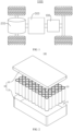
- FIG. 1 is a schematic structural diagram of a vehicle 1000 provided according to some embodiments of this application.
- the vehicle 1000 is provided with a battery 100 inside, and the battery 100 may be disposed at a bottom or head or tail of the vehicle 1000.
- the battery 100 may be configured to supply power to the vehicle 1000.
- the battery 100 may be used as an operational power supply for the vehicle 1000.
- the vehicle 1000 may also include a controller 200 and a motor 300, and the controller 200 is configured to control the battery 100 to power the motor 300, such as for the working power needs of the vehicle 1000 during start-up, navigation, and travelling.
- the battery 100 may serve not only as the operational power supply of the vehicle 1000, but also as a driving power supply of the vehicle 1000, replacing or partially replacing fuel or natural gas to provide driving power for the vehicle 1000.
- FIG. 2 is a schematic structural diagram of a battery 100 according to some embodiments of this application.
- the battery 100 includes a case 10 and a battery cell 20, and the battery cell 20 is accommodated within the case 10.
- the case 10 is used to provide mounting space 11 for the battery cell 20.
- the case 10 may include a first portion 12 and a second portion 13, where the first portion 12 caps the second portion 13, to define the mounting space 11 for accommodating the battery cell 20.
- a junction between the first portion 12 and the second portion 13 may be sealed by a sealing member (not shown in the figures), which may be a sealing ring, a sealing gum, or the like.
- the first portion 12 and the second portion 13 may be in various shapes, such as rectangular and cylindrical.
- the first portion 12 may be of a hollow structure with an opening on one side to form an accommodating cavity for accommodating the battery cell 20, and the second portion 13 may also be of a hollow structure with an opening on one side to form the accommodating cavity for accommodating the battery cell 20.
- the opening side of the first portion 12 caps the opening side of the second portion 13, the case 10 with the mounting space 11 is formed.
- the first portion 12 is of a hollow structure with an opening on one side to form an accommodating cavity for accommodating the battery cell 20, and the second portion 13 is of a plate structure.
- the opening side of the first portion 12 caps the second portion 13, the case 10 with the mounting space 11 is formed.
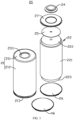
- FIG. 3 is an exploded view of the battery cell 20 according to some embodiments of this application.
- the battery cell 20 includes a shell 21 and an electrode assembly 22, and the electrode assembly 22 is accommodated in the shell 21.
- the electrode assembly 22 includes a first electrode plate (not shown in the figure), a second electrode plate (not shown in the figure), and a separator (not shown in the figure), and the separator is used to separate the first electrode plate from the second electrode plate.
- Polarity of the first electrode plate is opposite to polarity of the second electrode plate, in other words, one of the first electrode plate and the second electrode plate is a positive electrode plate, and the other of the first electrode plate and the second electrode plate is a negative electrode plate.
- the first electrode plate, the second electrode plate, and the separator are all of strip structures, and the first electrode plate, the second electrode plate, and the separator are stacked and coiled as one piece to form a coiled structure.
- the coiled structure may be a cylindrical structure, a flat structure, or a structure in another shape.
- the positive electrode plate includes a positive current collector and a positive active material layer, and a surface of the positive current collector is coated with the positive active material layer.
- the positive current collector not coated with the positive active material layer protrudes compared with the positive current collector coated with the positive active material layer, and the positive current collector not coated with the positive active material layer serves as a positive electrode tab.
- a material of the positive electrode current collector may be aluminum, and a positive electrode active material may be lithium cobaltate, lithium iron phosphate, ternary lithium, lithium manganate, or the like.
- the negative electrode plate includes a negative current collector and a negative active material layer, and a surface of the negative current collector is coated with the negative active material layer.
- the negative current collector not coated with the negative active material layer protrudes compared with the negative current collector coated with the negative active material layer, and the negative current collector not coated with the negative active material layer serves as a negative electrode tab.
- a material of the negative electrode current collector may be copper, and a negative electrode active material may be carbon, silicon, or the like.
- the separator may be made of polypropylene (PP), polyethylene (PE), or the like.
- the electrode assembly 22 may be of a coiled structure or a laminated structure, and embodiments of this application are not limited thereto.
- the electrode assembly 22 includes a main body portion 221, a first tab 222, and a second tab 223, and the first tab 222 and the second tab 223 protrude from the main body portion 221.
- the first tab 222 is a portion of the first electrode plate not coated with an active material layer
- the second tab 223 is a portion of the second electrode plate not coated with an active material layer.
- the first tab 222 and the second tab 223 are used for extracting a current in the main body portion 221.
- the first tab 222 and the second tab 223 may be located on the same side of the main body portion 221, which may be understood as that the first tab 222 and the second tab 223 are located at the same end of the electrode assembly 22 along a first direction.
- the first tab 222 and the second tab 223 may alternatively be located on two opposite sides of the main body portion 221, which may be understood as that the first tab 222 and the second tab 223 are located at two opposite ends of the electrode assembly 22 along a first direction.
- the first direction is parallel to a direction of a winding axis line of the electrode assembly 22.
- the shell 21 includes a bottom wall 211 and a side wall 212, and the bottom wall 211 encloses an outer periphery of the bottom wall 211.
- the shell 21 has an opening 213, and the opening 213 is provided opposite to the bottom wall 211.
- the electrode assembly 22 can enter the shell 21 via the opening 213.
- the battery cell 20 further includes an end cap 28, and the end cap 28 is used for capping the opening 213.
- the bottom wall 211 of the shell 21 is provided with an electrode extraction hole 2111.
- the battery cell 20 further includes an electrode terminal 24, the electrode terminal 24 is provided in the electrode extraction hole 2111 in an insulated manner, the electrode terminal 24 is used for electrically connecting to the first tab 222, and the electrode terminal 24 serves as a first output electrode of the battery cell 20.
- the electrode terminal 24 and the first tab 222 may be directly electrically connected or may be indirectly electrically connected via a first current collection member 25.
- the second tab 223 is electrically connected to the bottom wall 211, and the bottom wall 211 serves as a second output electrode of the battery cell 20.
- a bus component may be located on the same side of the battery cell 20 in the first direction to enable a plurality of battery cells 20 to be connected in series and/or in parallel.
- the second tab 223 may be electrically connected to the end cap 28.
- the second tab 223 and the end cap 28 may be directly electrically connected or may be indirectly electrically connected via a second current collection member 26.
- the end cap 28 and the shell 21 may be electrically connected, so that the end cap 28 and the shell 21 may have identical polarity, or the end cap 28 and the shell 21 may alternatively be in an insulated connection.
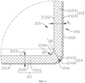
- FIG. 4 shows a partial sectional view of a shell 21 according to an embodiment of this application.
- the shell 21 includes a bottom wall 211 and a side wall 212, where the side wall 212 encloses an outer periphery of the bottom wall 211, where an outer surface 2112 of the bottom wall and an outer surface 2121 of the side wall are connected by a first rounding surface 2141, a thickness of the bottom wall 211 is a, and a radius of the first rounding surface 2141 is R1 that satisfies: R1/a ⁇ 10.
- the thickness a of the bottom wall 211 is a distance between the outer surface 2112 of the bottom wall and an inner surface 2113 of the bottom wall along a thickness direction of the bottom wall 211.
- the "outer surface 2112 of the bottom wall” is a surface of the bottom wall 211 furthest away from the interior of the shell 21 along the thickness direction of the bottom wall 211.
- the “inner surface 2113 of the bottom wall” is a surface of the bottom wall 211 closest to the interior of the shell 21 along the thickness direction of the bottom wall 211.
- the shell 21 further includes a transition wall 214, the side wall 212 encloses the outer periphery of the bottom wall 211, and the side wall 212 and the bottom wall 211 are connected by the transition wall 214.
- the side wall 212 encloses the outer periphery of the bottom wall 211, so that along the thickness direction of the bottom wall 211, a projection of the bottom wall 211 on the side wall 212 is located within space enclosed by the side wall 212.
- the first rounding surface 2141 is an outer surface of the transition wall 214, and the "outer surface of the transition wall 214" means a surface of the transition wall 214 furthest away from the interior of the shell 21 along a thickness direction of the transition wall 214.
- the "outer surface 2121 of the side wall” is a surface of the side wall 212 furthest away from the interior of the shell 21 along a thickness direction of the side wall 212.
- the outer surface 2112 of the bottom wall and the outer surface 2121 of the side wall are connected by the first rounding surface 2141.
- the first rounding surface 2141 extends from the outer surface 2112 of the bottom wall to the outer surface 2121 of the side wall. If a ratio of the radius R1 of the first rounding surface 2141 to the thickness a of the bottom wall 211 is too large, accordingly, a size of a transition surface between the inner surface 2113 of the bottom wall and the inner surface 2122 of the side wall is large., which may be understood as that space of a corner between the bottom wall 211 and the side wall 212 is large.
- the electrode assembly 22 is often not in contact with a curved surface of the corner, and consequently the space of the corner is wasted, and consequently the space of the corner is wasted, and space inside the shell 21 cannot be fully utilized, which reduces energy density of the battery cell 20.
- energy of the battery cell 20 is lower when R1/a is 15, and decreases with a large amplitude compared with energy that exists when R1/a is 1.2, 1.5, 5, or 10.
- R 1 /a is 1.2, 1.5, 5, or 10
- a fluctuation amplitude is small and the energy is higher compared with the energy that exists when R 1 /a is 15.
- the size of the transition surface between the inner surface 2113 of the bottom wall and the inner surface 2122 of the side wall can be within a reasonable range, so that a size of the space of the corner between the bottom wall 211 and the side wall 212 is within a reasonable range, thereby avoiding excessive waste of the space inside the shell 21, and helping increase the energy density of the battery cell 20.
- the battery cell 20 can have higher energy.
- R1/a may be 1.5, 5, or 10.
- Stamping is a processing method with high production efficiency and low material consumption. Therefore, stamping and molding are often used for the shell 21. Still referring to Table 1, when R 1 /a ⁇ 1.2, if stamping and molding are used for the shell 21, a material at the transition wall 214 is squeezed toward the bottom wall 211, which causes deformation of the bottom wall 211, and it is difficult for stamping and molding, or even it is impossible to implement stamping.
- R 1 /a ⁇ 1.2 R 1 /a ⁇ 1.2.
- R1 may be 0.88 mm, 0.9 mm, 0.96 mm, 1.2 mm, 4 mm, 8 mm, 9 mm, 10 mm, or the like.
- the first rounding surface 2141 satisfies: 0.8 mm ⁇ R 1 ⁇ 12 mm, which facilitates processing and manufacturing, and enables a molded shell 21 to meet practical application requirements.
- the value of R1 may be 1.1 mm, 1.2 mm, 1.3 mm, 1.4 mm, or the like.
- the first rounding surface 2141 satisfies: 1 mm ⁇ R 1 ⁇ 1.5 mm, which further facilitates processing and manufacturing of the first rounding surface 2141, and enables the molded shell 21 to meet practical application requirements.
- Table 1 shows cases in which a is 0.4 mm, 0.6 mm, 0.8 mm, or 1 mm. In other embodiments, a may alternatively be another value. For example, a is 0.5 mm, 0.7 mm, or 0.9 mm.
- the thickness a of the bottom wall 211 satisfies: 0.4 mm ⁇ a ⁇ 1 mm, which can ensure that the shell 21 has good structural strength and facilitates formation of the first rounding surface 2141.
- the arc length L 1 of the first rounding surface 2141 satisfies: 1.5 mm ⁇ L 1 ⁇ 4.7 mm, which facilitates processing and molding of the first rounding surface 2141.
- an angle between the bottom wall 211 and the side wall 212 is 90°.
- a thickness b of the side wall 212 is different from the thickness a of the bottom wall 211.
- the thickness b of the side wall 212 is less than the thickness a of the bottom wall 211.
- the tangent plane of the first end portion and the outer surface 2121 of the side wall are arranged with an included angle, and a connection position between the first rounding surface 2141 and the outer surface 2121 of the side wall form a sharp angle.
- a larger angle between the tangent plane of the first end portion and the outer surface 2121 of the side wall indicates a more protrudent sharp angle, which easily leads to scratching of the shell 21.
- the angle between the tangent plane of the first end portion of the first rounding surface 2141 and the outer surface 2121 of the side wall is less than or equal to 30°, so that the sharp angle between the first rounding surface 2141 and the outer surface 2121 of the side wall is reduced, thereby providing good smoothness between the first rounding surface 2141 and the outer surface 2121 of the side wall, and reducing a risk of scratching of the shell 21.
- ⁇ may be 0°, 10°, or 15°.
- the first rounding surface 2141 further has a second end portion connected to the outer surface 2112 of the bottom wall, and the outer surface 2112 of the bottom wall is tangent to the second end portion. That is, the outer surface 2112 of the bottom wall is a tangent plane of the second end portion, and there is no sharp angle but a smooth transition between the second end portion and the outer surface 2112 of the bottom wall.
- the thickness of the side wall 212 is b that satisfies: 0.2 mm ⁇ b ⁇ 0.8 mm.
- b may be 0.4 mm, 0.45 mm, 0.5 mm, 0.6 mm, 0.7 mm, or the like.
- the thickness b of the side wall 212 satisfies: 0.2 mm ⁇ b ⁇ 0.8 mm, which can ensure that the side wall 212 of the shell 21 has good structural strength.
- the inner surface 2113 of the bottom wall and the inner surface 2122 of the side wall are connected by a second rounding surface 2142.
- the second rounding surface 2142 is an inner surface of the transition wall 214, which may be understood as that the transition wall 214 is a rounded wall.
- the "inner surface of the transition wall 214" is a surface of the transition wall 214 closest to the interior of the shell 21 along the thickness direction of the transition wall 214.
- the “inner surface 2122 of the side wall” is a surface of the side wall 212 closest to the interior of the shell 21 along the thickness direction of the side wall 212.
- the inner surface 2113 of the bottom wall and the inner surface 2122 of the side wall are connected by the second rounding surface 2142, so that the bottom wall 211 and the side wall 212 can have the smooth transition, and a risk of stress concentration is reduced.
- a radius of the second rounding surface 2142 is R 2 , where 0.4 mm ⁇ R 2 ⁇ 1.2 mm.
- a value of R 2 may be 0.5 mm, 0.6 mm, 0.8 mm, 1 mm, or the like.
- the radius R 2 of the second rounding surface 2142 satisfies 0.4 mm ⁇ R 2 ⁇ 1.2 mm, which facilitates processing and molding of the second rounding surface 2142, and enables the size of the space of the corner between the bottom wall 211 and the side wall 212 to be within a reasonable range, so as to avoid waste of the space inside the shell 21.
- R 2 may be 0.55 mm, 0.65 mm, 0.7 mm, 0.75 mm, 0.85 mm, 0.9 mm, 0.95 mm, or the like.
- the radius R 2 of the second rounding surface 2142 satisfies 0.5 mm ⁇ R 2 ⁇ 1 mm, which facilitates processing and molding of the second rounding surface 2142, and further reduces the size of the space of the corner between the bottom wall 211 and the side wall 212, so as to avoid waste of the space inside the shell 21, thereby increasing the energy of the battery cell 20.
- an arc length of the second rounding surface 2142 is L 2 that satisfies: 0.7 mm ⁇ L 2 ⁇ 3.2 mm.
- the "arc length of the second rounding surface 2142" is a length of the second rounding surface 2142 extending from the inner surface 2113 of the bottom wall toward the inner surface 2122 of the side wall.
- L 2 may be 1 mm, 1.3 mm, 1.8 mm, 2.2 mm, 2.8 mm, or 3 mm.
- the arc length L 2 of the second rounding surface 2142 satisfies: 0.7 mm ⁇ L 2 ⁇ 3.2 mm, so that processing of the second rounding surface 2142 is easier.
- the shell 21 includes a main body layer 215 and an antioxidant layer 216, and the antioxidant layer 216 is provided on an outer surface of the main body layer 215.
- the main body layer 215 is a main structure of the shell 21, and a material of the main body layer 215 needs to enable the shell 21 to have good strength and stiffness.
- the material of the main body layer 215 is steel.
- the antioxidant layer 216 is formed by a material with good antioxidant performance.
- the antioxidant layer 216 may be made of nickel, tin, or gold.
- the antioxidant layer 216 may be provided on the outer surface of the main body layer 215 in a manner of plating, coating, pasting, or the like.
- the antioxidant layer 216 may be provided on the surface of the main body layer 215 before the main body layer 215 is stamped, or may be provided on the surface of the main body layer 215 after the main body layer 215 is stamped.
- the transition wall 214 includes a first main body layer 2143 and a first antioxidant layer 2144, the first antioxidant layer 2144 is provided on an outer surface of the first main body layer 2143, and the first rounding surface 2141 is formed on a surface of the first antioxidant layer 2144 facing away from the first main body layer 2143.
- the bottom wall 211 includes a second main body layer 2114 and a second antioxidant layer 2115, the second main body layer 2114 is connected to the first main body layer 2143, the second antioxidant layer 2115 is provided on an outer surface of the second main body layer 2114 and is connected to the first antioxidant layer 2144, and the outer surface 2112 of the bottom wall is formed on a surface of the second antioxidant layer 2115 facing away from the second main body layer 2114.
- the thickness a of the bottom wall 211 is a sum of a thickness of the second main body layer 2114 and a thickness of the second antioxidant layer 2115.
- the side wall 212 includes a third main body layer 2123 and a third antioxidant layer 2124, the third main body layer 2123 is connected to the first main body layer 2143, the third antioxidant layer 2124 is provided on an outer surface of the third main body layer 2123 and is connected to the first antioxidant layer 2144, and the outer surface 2121 of the side wall is formed on a surface of the third antioxidant layer 2124 facing away from the third main body layer 2123.
- the thickness b of the side wall 212 is a sum of a thickness of the third main body layer 2123 and a thickness of the third antioxidant layer 2124.
- the first main body layer 2143, the second main body layer 2114, and the third main body layer 2123 together form the main body layer 215 of the shell 21, and the first main body layer 2143, the second main body layer 2114, and the third main body layer 2123 are molded as one piece.
- the first antioxidant layer 2144, the second antioxidant layer 2115, and the third antioxidant layer 2124 together form the antioxidant layer 216 of the shell 21.
- the antioxidant layer 216 is provided on the outer surface of the main body layer 215, so as to provide the main body layer 215 with good antioxidant performance, thereby improving an anti-corrosion capability of the shell 21.
- the antioxidant layer 216 In an embodiment in which the antioxidant layer 216 is provided on the surface of the main body layer 215 before the main body layer 215 is stamped, the antioxidant layer 216 stretches at the transition wall 214 during stamping, and the antioxidant layer 216 cracks in a severe situation. Therefore, in some embodiments, the first rounding surface 2141 is formed on an outer surface of the antioxidant layer 216, and the second rounding surface 2142 is formed on an inner surface of the main body layer 215; and the arc length Li of the first rounding surface 2141 and the arc length L 2 of the second rounding surface 2142 satisfy: 1 ⁇ L 1 /L 2 ⁇ 1.6.
- An extension amount of the second rounding surface 2142 during stamping is small and negligible, which may be understood as that an arc length of the second rounding surface 2142 after stamping is equal to an original length of the second rounding surface 2142 before stamping.
- a length of the first rounding surface 2141 in an original state is equal to the original length of the second rounding surface 2142, so that an original length of the first rounding surface 2141 can equate to the arc length of the second rounding surface 2142.
- L 1 /L 2 may be understood as a ratio of a length of the first rounding surface 2141 after stamping to a length of the first rounding surface 2141 before stamping, and it can be learned that the extension amount of the first rounding surface 2141 ranges from 0 to 0.6, that is, 0 ⁇ (L 1 -L 2 )/L 2 ⁇ 0.6.
- the arc length L1 of the first rounding surface 2141 and the arc length L2 of the second rounding surface 2142 satisfy 1 ⁇ L 1 /L 2 ⁇ 1.6, which can ensure that the antioxidant layer 216 does not crack during molding of the first rounding surface 2141 and the second rounding surface 2142.
- the shell 21 is of a cylindrical structure. Then, the formed battery cell 20 is a cylindrical battery cell 20.
- the size of the space of the corner between the bottom wall 211 and the side wall 212 of the shell 21 of the cylindrical structure is within a reasonable range, thereby avoiding excessive waste of the space inside the shell 21, and helping increase the energy density of the battery cell 20.
- Embodiments of this application further provide a battery cell 20.
- the battery cell 20 includes the shell 21 and the electrode assembly 22 according to any one of the above embodiments, and the electrode assembly 22 is accommodated within the shell 21.
- the battery cell 20 is a cylindrical battery cell 20.
- a size of space of a corner between a bottom wall 211 and a side wall 212 of a shell 21 of the battery cell 20 with the shell 21 according to any embodiment of the first aspect is within a reasonable range, thereby avoiding excessive waste of space inside the shell 21, and helping increase energy density of the battery cell 20.
- the shell 21 has an opening 213 provided opposite to the bottom wall 211.
- the battery cell 20 further includes an end cap 28, and the end cap 28 is used for capping the opening 213.
- the bottom wall 211 and the opening 213 are provided at two ends of the shell 21 along an axial direction respectively, and the opening 213 is enclosed by the side wall 212.
- the electrode assembly 22 can enter the shell 21 via the opening 213.
- the opening 213 is then capped with the end cap 28.
- the end cap 28 may be electrically connected to the shell 21 or may be connected via an insulating member.
- the shell 21 is provided with the opening 213, to facilitate assembly of the electrode assembly 22 into the shell 21.
- the opening 213 can be capped by the end cap 28 to improve sealing and security of the battery cell 20.
- the battery cell 20 further includes an electrode terminal 24, the bottom wall 211 is provided with an electrode extraction hole 2111, the electrode terminal 24 is provided in the electrode extraction hole 2111 in an insulated manner, the electrode terminal 24 is used for electrically connecting to a first tab 222 of the electrode assembly 22, the bottom wall 211 is electrically connected to a second tab 223 of the electrode assembly 22, and polarity of the first tab 222 is opposite to that of the second tab 223.
- the electrode terminal 24 may be located within the electrode extraction hole 2111. In other embodiments, the electrode terminal 24 and the electrode extraction hole 2111 may alternatively have another relative position relationship. For example, the electrode terminal 24 is located on a side of the end cap 28facing the electrode assembly 22, and a projection of the electrode terminal 24 on the end cap 28 is located within the electrode extraction hole 2111 along a thickness direction of the end cap 28, so that the electrode terminal 24 can be exposed to the outside through the electrode extraction hole 2111, to facilitate an electrical connection between the electrode terminal 24 and another device.
- the first tab 222 and the second tab 223 may be located on the same side of the electrode assembly 22 or two opposite sides of the electrode assembly 22.
- the electrode terminal 24 is electrically connected to the first tab 222 and serves as a first output electrode of the battery cell 20, the second tab 223 of which polarity is opposite to that of the first tab 222 is electrically connected to the bottom wall 211 to enable the bottom wall 211 to serve as a second output electrode of the battery cell 20, and the bottom wall 211 and the electrode terminal 24 are located at the same end of the battery cell 20.
- the first tab 222 and the second tab 223 can be located at the same side of the battery cell 20, which simplifies an assembly process and improves efficiency of connecting a plurality of battery cells 20 in series, in parallel, or in a mixed connection as a battery module.
- the battery cell 20 further includes a first insulating member 27, and the first insulating member 27 is provided between the bottom wall 211 and the electrode terminal 24.
- Embodiments of this application further provide a battery 100, and the battery 100 includes the battery cell 20 according to any one of the above embodiments.
- Embodiments of this application further provide an electric device, and the electric device includes the battery cell 20 according to any one of the above embodiments.
- Embodiments of this application provide a cylindrical shell 21 of a cylindrical battery 100, the cylindrical shell 21 includes a bottom wall 211, a side wall 212, and a curved transition wall 214, and the bottom wall 211 and the side wall 212 are connected by the curved transition wall 214.
- An outer surface of the transition wall 214 is a first rounding surface 2141, and an inner surface of the transition wall 214 is a second rounding surface 2142.
- An outer surface 2112 of the bottom wall and an outer surface 2121 of the side wall are connected by the first rounding surface 2141, and an inner surface 2113 of the bottom wall and an inner surface 2122 of the side wall are connected by the second rounding surface 2142.
- a thickness of the bottom wall 211 is a
- a radius of the first rounding surface 2141 is R 1 that satisfies 1.2 ⁇ R 1 /a ⁇ 10.
- a size of a transition surface between the inner surface 2113 of the bottom wall and the inner surface 2122 of the side wall can be within a reasonable range, so that a size of space of a corner between the bottom wall 211 and the side wall 212 is within a reasonable range, thereby avoiding excessive waste of space inside the shell 21, and helping increase energy density of the battery cell 20.
- the radius R 1 of the first rounding surface 2141 satisfies: 1 mm ⁇ R 1 ⁇ 1.5 mm, so that the first rounding surface 2141 can not only be stamped and molded normally, but the battery cell 20 also has large energy.
- the thickness a of the bottom wall 211 satisfies: 0.4 mm ⁇ a ⁇ 1 mm, which can ensure that the shell 21 has good structural strength and facilitates formation of the first rounding surface 2141.
- An arc length of the first rounding surface 2141 is L 1 that satisfies: 1.5 mm ⁇ L 1 ⁇ 4.7 mm, which facilitates processing and molding of the first rounding surface 2141.
- An angle ⁇ between the outer surface 2121 of the side wall and a tangent plane of a first end portion of the first rounding surface for connecting to the outer surface 2121 of the side wall is less than or equal to 30°, so that a sharp angle between the first rounding surface 2141 and the outer surface 2121 of the side wall is reduced, thereby providing good smoothness between the first rounding surface 2141 and the outer surface 2121 of the side wall, and reducing a risk of scratching of the shell 21.
- a radius of the second rounding surface 2142 is R 2 , and 0.5 mm ⁇ R 2 ⁇ 1 mm, which facilitates processing and molding of the second rounding surface 2142, and enables the size of the space of the corner between the bottom wall 211 and the side wall 212 to be within a reasonable range, so as to avoid waste of the space inside the shell 21.
- An arc length of the second rounding surface 2142 is L 2 that satisfies: 0.7 mm ⁇ L 2 ⁇ 3.2 mm, so that processing of the second rounding surface 2142 is easier.
- the shell 21 includes a main body steel layer and a nickel layer, and the nickel layer is plated on an outer surface of the main body steel layer. After the nickel layer is plated on the surface of the main body steel layer to form a composite structure, the composite structure is stamped to form the shell 21, and the nickel layer is provided on the outer surface of the main body steel layer.
- the first rounding surface 2141 is formed on an outer surface of the nickel layer, and the second rounding surface 2142 is formed on an inner surface of the main body steel layer.
- the arc length L 1 of the first rounding surface 2141 and the arc length L 2 of the second rounding surface 2142 satisfy: 1 ⁇ L 1 /L 2 ⁇ 1.6, which can ensure that an antioxidant layer 216 does not crack during molding of the first rounding surface 2141 and the second rounding surface 2142.
Landscapes
- Chemical & Material Sciences (AREA)
- Chemical Kinetics & Catalysis (AREA)
- Electrochemistry (AREA)
- General Chemical & Material Sciences (AREA)
- Engineering & Computer Science (AREA)
- Sustainable Development (AREA)
- Life Sciences & Earth Sciences (AREA)
- Sustainable Energy (AREA)
- Power Engineering (AREA)
- Transportation (AREA)
- Mechanical Engineering (AREA)
- Inorganic Chemistry (AREA)
- Sealing Battery Cases Or Jackets (AREA)
Abstract
Description
- This application claims priority to
Chinese Patent Application No. 202221231517.8, filed on May 20, 2022 - This application relates to the technical field of batteries, and in particular, to a shell, a battery cell, a battery, and an electric device.
- Currently, with the rapid development of smartphones, tablet computers, electric vehicles, and the like, and more widespread applications of lithium-ion batteries, higher requirements are proposed for the lithium-ion battery. For example, the battery is required to have high energy density, so that the lithium battery has a better battery life. Therefore, how to improve the energy density of the battery has become an urgent problem to be resolved in the technical field of batteries.
- Embodiments of this application provide a shell, a battery cell, a battery, and an electric device, to improve energy density of the battery.
- According to a first aspect, embodiments of this application provide a shell. The shell includes a bottom wall and a side wall, where the side wall encloses an outer periphery of the bottom wall, an outer surface of the bottom wall and an outer surface of the side wall are connected by a first rounding surface, a thickness of the bottom wall is a, and a radius of the first rounding surface is R1 that satisfies: R1/a ≤ 10.
- In the above technical solution, the outer surface of the bottom wall and the outer surface of the side wall are connected by the first rounding surface. The first rounding surface extends from the outer surface of the bottom wall to the outer surface of the side wall. If a ratio of the radius R1 of the first rounding surface to the thickness a of the bottom wall is too large, accordingly, a size of a transition surface between an inner surface of the bottom wall and an inner surface of the side wall is large, which may be understood as that space of a corner between the bottom wall and the side wall is large. Because an electrode assembly is often not in contact with a curved surface at the corner, the space of the corner is wasted, and consequently space inside the shell cannot be fully utilized, which reduces energy density of a battery cell. Nevertheless, as R1/a ≤ 10, the size of the transition surface between the inner surface of the bottom wall and the inner surface of the side wall can be within a reasonable range, so that a size of the space of the corner between the bottom wall and the side wall is within a reasonable range, thereby avoiding excessive waste of the space inside the shell, and helping increase the energy density of the battery cell.
- In some embodiments of the first aspect of this application, R1/a ≥ 1.2.
- In the above technical solution, as R1/a ≥ 1.2, material accumulation at a transition position between the inner surface of the side wall and the inner surface of the side wall can be reduced or avoided, and a risk of deformation of the bottom wall caused by excessive material accumulation at the transition position between the inner surface of the side wall and the inner surface of the side wall and by squeezing toward a side of the bottom wall can also be reduced.
- In some embodiments of the first aspect of this application, 0.8 mm ≤ R1 ≤ 12 mm.
- In the above technical solution, the first rounding surface R1 satisfies: 0.8 mm ≤ R1 ≤ 12 mm, which facilitates processing and manufacturing of the first rounding surface, and enables a molded shell to meet practical application requirements.
- In some embodiments of the first aspect of this application, 1 mm ≤ R1 ≤ 1.5 mm.
- In the above technical solution, the first rounding surface R1 satisfies: 1 mm ≤ R1 ≤ 1.5 mm, which facilitates processing and manufacturing of the first rounding surface, and enables the molded shell to meet practical application requirements.
- In some embodiments of the first aspect of this application, 0.4 mm ≤ a ≤ 1 mm.
- In the above technical solution, the thickness a of the bottom wall satisfies: 0.4 mm ≤ a ≤ 1 mm, which can ensure that the shell has good structural strength and facilitates formation of the first rounding surface.
- In some embodiments of the first aspect of this application, an arc length of the first rounding surface is L1 that satisfies: 1.5 mm ≤ L1 ≤ 4.7 mm.
- In the above technical solution, the arc length L1 of the first rounding surface satisfies: 1.5 mm ≤ L1 ≤ 4.7 mm, which facilitates processing and molding of the first rounding surface.
- In some embodiments of the first aspect of this application, the first rounding surface has a first end portion connected to the outer surface of the side wall, and an angle between a tangent plane of the first end portion of the first rounding surface and the outer surface of the side wall is θ that satisfies: θ ≤ 30°.
- In the above technical solution, the angle between the tangent plane of the first end portion of the first rounding surface and the outer surface of the side wall is less than or equal to 30°, so that a sharp angle between the first rounding surface and the outer surface of the side wall is reduced, thereby providing good smoothness between the first rounding surface and the outer surface of the side wall.
- In some embodiments of the first aspect of this application, a thickness of the side wall is b that satisfies: 0.2 mm ≤ b ≤ 0.8 mm.
- In the above technical solution, the thickness b of the side wall satisfies: 0.2 mm ≤ b ≤ 0.8 mm, which can ensure that the side wall of the shell has good structural strength.
- In some embodiments of the first aspect of this application, an inner surface of the bottom wall and an inner surface of the side wall are connected by a second rounding surface.
- In the above technical solution, the inner surface of the bottom wall and the inner surface of the side wall are connected by the second rounding surface, so that the bottom wall and the side wall can have a smooth transition, and a risk of stress concentration is reduced.
- In some embodiments of the first aspect of this application, a radius of the second rounding surface is R2, where 0.4 mm ≤ R2 ≤ 1.2 mm.
- In the above technical solution, the radius R2 of the second rounding surface satisfies 0.4 mm ≤ R2 ≤ 1.2 mm, which facilitates processing and molding of the second rounding surface, and enables the size of the space of the corner between the bottom wall and the side wall to be within a reasonable range, so as to avoid waste of the space inside the shell.
- In some embodiments of the first aspect of this application, 0.5 mm ≤ R2 ≤ 1 mm.
- In the above technical solution, the radius R2 of the second rounding surface satisfies 0.5 mm ≤ R2 ≤ 1 mm, which facilitates processing and molding of the second rounding surface, and further reduces the size of the space of the corner between the bottom wall and the side wall, so as to avoid waste of the space inside the shell.
- In some embodiments of the first aspect of the application, an arc length of the second rounding surface is L2 that satisfies: 0.7 mm ≤ L2 ≤ 3.2 mm.
- In the above technical solution, the arc length L2 of the second rounding surface satisfies: 0.7 mm ≤ L2 ≤ 3.2 mm, so that processing of the second rounding surface is easier.
- In some embodiments of the first aspect of this application, the shell includes a main body layer and an antioxidant layer, and the antioxidant layer is provided on an outer surface of the main body layer.
- In the above technical solution, the antioxidant layer is provided on the outer surface of the main body layer, so as to provide the main body layer with good antioxidant performance, thereby improving an anti-corrosion capability of the shell.
- In some embodiments of the first aspect of this application, the inner surface of the bottom wall and the inner surface of the side wall are connected by the second rounding surface, the first rounding surface is formed on an outer surface of the antioxidant layer, and the second rounding surface is formed on an inner surface of the main body layer; and the arc length L1 of the first rounding surface and the arc length L2 of the second rounding surface satisfy: 1 ≤ L1/L2 ≤ 1.6.
- In the above technical solution, the arc length L1 of the first rounding surface and the arc length L2 of the second rounding surface satisfy 1 ≤ L1/L2 ≤ 1.6, which can ensure that the antioxidant layer does not crack during molding of the first rounding surface and the second rounding surface.
- In some embodiments of the first aspect of this application, the shell is of a cylindrical structure.
- In the above technical solution, the size of the space at the corner between the bottom wall and the side wall of the shell of the cylindrical structure is within a reasonable range, thereby avoiding excessive waste of the space inside the shell, and helping increase the energy density of the battery cell.
- According to a second aspect, embodiments of this application provide a battery cell. The battery cell includes the shell according to embodiments of the first aspect and an electrode assembly, where the electrode assembly is accommodated in the shell.
- In the above technical solution, a size of space at a corner between a bottom wall and a side wall of a shell of the battery cell with the shell according to any embodiment of the first aspect is within a reasonable range, thereby avoiding excessive waste of space inside the shell, and helping increase energy density of the battery cell.
- In some embodiments of the second aspect of this application, the shell has an opening provided opposite to a bottom wall, the battery cell further includes an end cap, and the end cap is used for capping the opening.
- In the above technical solution, the shell is provided with the opening, to facilitate assembly of the electrode assembly into the shell. After the electrode assembly is accommodated in the shell, the opening can be capped by the end cap to improve sealing and security of the battery cell.
- In some embodiments of the second aspect of this application, the battery cell further includes an electrode terminal, the bottom wall is provided with an electrode extraction hole, the electrode terminal is provided in the electrode extraction hole in an insulated manner, the electrode terminal is used for electrically connecting to a first tab of the electrode assembly, the bottom wall is electrically connected to a second tab of the electrode assembly, and polarity of the first tab is opposite to that of the second tab.
- In the above technical solution, the electrode terminal is electrically connected to the first tab and serves as a first output electrode of the battery cell, the second tab of which polarity is opposite to that of the first tab is electrically connected to the bottom wall to enable the bottom wall to serve as a second output electrode of the battery cell, and the bottom wall and the electrode terminal are located at the same end of the battery cell. In this way, the first tab and the second tab can be located at the same side of the battery cell, which simplifies an assembly process and improves efficiency of connecting a plurality of battery cells in series, in parallel, or in a mixed manner as a battery module.
- According to a third aspect, embodiments of this application provide a battery. The battery includes the battery cell provided in the embodiments of the second aspect.
- According to a fourth aspect, embodiments of this application provide an electric device. The electric device includes the battery cell provided in the embodiments of the second aspect.
- To describe the technical solutions in embodiments of this application more clearly, the following outlines the drawings to be used in embodiments. It should be understood that the drawings below are merely some embodiments of this application and should therefore not be regarded as limiting the scope. A person of ordinary skill in the art may derive other related drawings from such drawings without making any creative efforts.
-
FIG. 1 is a schematic structural diagram of a vehicle according to some embodiments of this application; -
FIG. 2 is a schematic structural diagram of a battery according to some embodiments of this application; -
FIG. 3 is an exploded view of a battery cell according to some embodiments of this application; -
FIG. 4 is a partial sectional view of a shell according to an embodiment of this application; -
FIG. 5 is a sectional view of a shell according to other embodiments of this application; and -
FIG. 6 is an enlarged view of A inFIG. 5 . - Reference numerals: 1000-vehicle; 100-battery; 10-case; 11-mounting space; 12-first portion; 13-second portion; 20-battery cell; 21-shell; 211-bottom wall; 2111-electrode extraction hole; 2112-outer surface of the bottom wall; 2113-inner surface of the bottom wall; 2114-second main body layer; 2115-second antioxidant layer; 212-side wall; 2121-outer surface of the side wall; 2122-inner surface of the side wall; 2123-third main body layer; 2124-third antioxidant layer; 213-opening; 214-transition wall; 2141-first rounding surface; 2142-second rounding surface; 2143-first main body layer; 2144-first antioxidant layer; 215-main body layer; 216-antioxidant layer; 22-electrode assembly; 221-main body portion; 222-first tab; 223-second tab; 24-electrode terminal; 25-first current collection member; 26-second current collection member; 27-first insulating member; 28-end cap; 200-controller; and 300-motor.
- To make the objectives, technical solutions, and advantages of embodiments of this application clearer, the following clearly and completely describes the technical solutions in embodiments of this application with reference to the accompanying drawings in embodiments of this application. It will be apparent that the described embodiments are merely some rather than all of embodiments of this application. Generally, components of embodiments of this application described and illustrated in the accompanying drawings herein may be arranged and designed in various different configurations.
- Accordingly, the following detailed descriptions of embodiments of this application provided in the accompanying drawings are not intended to limit the scope of this application for which protection is claimed, but rather represent only selected embodiments of this application. Based on the embodiments in this application, all other embodiments derived by a person of ordinary skill in the art without creative work shall fall within the scope of protection of this application.
- It is hereby noted that where there is no conflict, the embodiments in this application and the features in the embodiments may be mutually combined.
- It should be noted: Similar symbols and letters denote similar items in the following accompanying drawings, so that once an item is defined in one accompanying drawing, no further definition or explanation of the item is required in the subsequent accompanying drawings.
- In the descriptions of embodiments of this application, it should be noted that indication of orientations or positional relationships is based on orientations or positional relationships shown in the accompanying drawings, or orientations or positional relationships in which the product of the application is customarily placed in use, or orientations or positional relationships customarily understood by a person skilled in the art, is intended only for the purpose of facilitating the descriptions of this application and to simplify the descriptions, and does not indicate or imply that the apparatus or element referred to must have a particular orientation or be constructed and operated in a particular orientation, and therefore is not to be construed as a limitation of this application. In addition, the terms "first", "second", "third", and the like are used only for the purpose of differentiating descriptions and are not to be understood as indicating or implying relative importance.
- Currently, from a perspective of market development, application of traction batteries is becoming more and more extensive. The traction battery is not only applied to energy storage power systems such as hydroelectric, thermal, wind, and solar power stations, but is also widely used in electric transportation vehicles such as electric bicycles, electric motorcycles, and electric vehicles, as well as in various fields such as military equipment and aerospace. As application fields of the traction battery continue to expand, a market demand of the traction battery also expands.
- A battery cell includes a shell and an electrode assembly accommodated in the shell. The shell includes a bottom wall and a side wall, and an outer surface of the bottom wall and an outer surface of the side wall are transitionally connected by a first rounding surface.
- The inventors find that if a ratio of a radius R1 of the first rounding surface to a thickness a of the bottom wall is too large, accordingly, a size of a transition surface of an inner surface of the bottom wall and an inner surface of the side wall is large, which may be understood as that space of a corner between the bottom wall and the side wall is large. To avoid wrinkling of an electrode plate of the electrode assembly caused by squeezing between the electrode assembly and the corner, the electrode assembly is often not in contact with a curved surface of the corner, and consequently the space of the corner is wasted, which reduces energy density of the battery cell.
- Based on the above considerations, in order to fully utilize space inside the shell of the battery cell to improve the energy density of the battery cell, the inventors design a shell through thorough research, with the ratio R1/a of the radius R1 of the first rounding surface of the shell to the thickness a of the bottom wall satisfying: R1/a ≤ 10.
- As R1/a ≤ 10, the size of the transition surface between the inner surface of the bottom wall and the inner surface of the side wall can be within a reasonable range, so that a size of the space of the corner between the bottom wall and the side wall is within a reasonable range, thereby avoiding excessive waste of the space inside the shell, and helping increase the energy density of the battery cell.
- The shell disclosed in embodiments of this application can be used in the battery cell, and can also be used in other fields to accommodate other structures. The battery cell having the shell provided in embodiments of this application may be, but is not limited to, used in an electric device such as a vehicle, a ship, or an aircraft. The battery cell, a battery, and the like having the shell disclosed in this application can be used to form a power supply system of the electric device, which helps increase the energy density of the battery cell, energy density of the battery, and the like.
- Embodiments of this application provide an electric device using a battery as a power supply, and the electric device may be, but is not limited to, a cell phone, a tablet, a laptop computer, an electric toy, an electric tool, an electric scooter, an electric car, a ship, a spacecraft, and the like. The electric toy may include a fixed or mobile electric toy, for example, a game console, an electric toy car, an electric toy ship, and an electric toy airplane. The spacecraft may include an airplane, a rocket, a space shuttle, a spaceship, and the like.
- The following embodiments are illustrated as an example of the electric device as a vehicle of an embodiment of this application for the convenience of illustration.
- Referring to
FIG. 1, FIG. 1 is a schematic structural diagram of avehicle 1000 provided according to some embodiments of this application. Thevehicle 1000 is provided with abattery 100 inside, and thebattery 100 may be disposed at a bottom or head or tail of thevehicle 1000. Thebattery 100 may be configured to supply power to thevehicle 1000. For example, thebattery 100 may be used as an operational power supply for thevehicle 1000. - The
vehicle 1000 may also include acontroller 200 and amotor 300, and thecontroller 200 is configured to control thebattery 100 to power themotor 300, such as for the working power needs of thevehicle 1000 during start-up, navigation, and travelling. - In some embodiments of this application, the
battery 100 may serve not only as the operational power supply of thevehicle 1000, but also as a driving power supply of thevehicle 1000, replacing or partially replacing fuel or natural gas to provide driving power for thevehicle 1000. -
FIG. 2 is a schematic structural diagram of abattery 100 according to some embodiments of this application. Thebattery 100 includes a case 10 and abattery cell 20, and thebattery cell 20 is accommodated within the case 10. - The case 10 is used to provide mounting
space 11 for thebattery cell 20. In some embodiments, the case 10 may include afirst portion 12 and a second portion 13, where thefirst portion 12 caps the second portion 13, to define the mountingspace 11 for accommodating thebattery cell 20. Of course, a junction between thefirst portion 12 and the second portion 13 may be sealed by a sealing member (not shown in the figures), which may be a sealing ring, a sealing gum, or the like. - The
first portion 12 and the second portion 13 may be in various shapes, such as rectangular and cylindrical. Thefirst portion 12 may be of a hollow structure with an opening on one side to form an accommodating cavity for accommodating thebattery cell 20, and the second portion 13 may also be of a hollow structure with an opening on one side to form the accommodating cavity for accommodating thebattery cell 20. When the opening side of thefirst portion 12 caps the opening side of the second portion 13, the case 10 with the mountingspace 11 is formed. Of course, as shown inFIG. 2 , it is also possible that thefirst portion 12 is of a hollow structure with an opening on one side to form an accommodating cavity for accommodating thebattery cell 20, and the second portion 13 is of a plate structure. When the opening side of thefirst portion 12 caps the second portion 13, the case 10 with the mountingspace 11 is formed. - In the
battery 100, there may be one ormore battery cells 20. If there are a plurality ofbattery cells 20, the plurality ofbattery cells 20 may be connected in series, in parallel, or in a mixed connection, and the mixed connection means that the plurality ofbattery cells 20 are connected in series and in parallel. The plurality ofbattery cells 20 may be directly connected in series, in parallel, or in a mixed connection, and then a whole formed by the plurality ofbattery cells 20 is accommodated in the case 10; of course, it is also possible that the plurality ofbattery cells 20 are first connected in series or in parallel or in a mixed connection to form battery modules, and then a plurality of battery modules are connected in series or in parallel or in a mixed connection to form a whole that is accommodated in the case 10. Thebattery cell 20 may be in a cylindrical shape, a flat shape, a cuboid shape, or another shape.FIG. 2 illustrates a case in which thebattery cell 20 is in the cylindrical shape as an example. - In some embodiments, the
battery 100 may also include a bus component (not shown in the figure), and the plurality ofbattery cells 20 may be electrically connected to each other via the bus component, so that the plurality ofbattery cells 20 are connected in series, in parallel, or in a mixed connection. -
FIG. 3 is an exploded view of thebattery cell 20 according to some embodiments of this application. Thebattery cell 20 includes ashell 21 and anelectrode assembly 22, and theelectrode assembly 22 is accommodated in theshell 21. - The
electrode assembly 22 includes a first electrode plate (not shown in the figure), a second electrode plate (not shown in the figure), and a separator (not shown in the figure), and the separator is used to separate the first electrode plate from the second electrode plate. Polarity of the first electrode plate is opposite to polarity of the second electrode plate, in other words, one of the first electrode plate and the second electrode plate is a positive electrode plate, and the other of the first electrode plate and the second electrode plate is a negative electrode plate. The first electrode plate, the second electrode plate, and the separator are all of strip structures, and the first electrode plate, the second electrode plate, and the separator are stacked and coiled as one piece to form a coiled structure. The coiled structure may be a cylindrical structure, a flat structure, or a structure in another shape. - The positive electrode plate includes a positive current collector and a positive active material layer, and a surface of the positive current collector is coated with the positive active material layer. The positive current collector not coated with the positive active material layer protrudes compared with the positive current collector coated with the positive active material layer, and the positive current collector not coated with the positive active material layer serves as a positive electrode tab. Taking a lithium-ion battery as an example, a material of the positive electrode current collector may be aluminum, and a positive electrode active material may be lithium cobaltate, lithium iron phosphate, ternary lithium, lithium manganate, or the like. The negative electrode plate includes a negative current collector and a negative active material layer, and a surface of the negative current collector is coated with the negative active material layer. The negative current collector not coated with the negative active material layer protrudes compared with the negative current collector coated with the negative active material layer, and the negative current collector not coated with the negative active material layer serves as a negative electrode tab. A material of the negative electrode current collector may be copper, and a negative electrode active material may be carbon, silicon, or the like. In order to ensure that a high current is passed without fusing, there may be a plurality of positive tabs which are stacked together, and there may be a plurality of negative tabs which are stacked together. The separator may be made of polypropylene (PP), polyethylene (PE), or the like. In addition, the
electrode assembly 22 may be of a coiled structure or a laminated structure, and embodiments of this application are not limited thereto. - The
electrode assembly 22 includes amain body portion 221, afirst tab 222, and asecond tab 223, and thefirst tab 222 and thesecond tab 223 protrude from themain body portion 221. Thefirst tab 222 is a portion of the first electrode plate not coated with an active material layer, and thesecond tab 223 is a portion of the second electrode plate not coated with an active material layer. Thefirst tab 222 and thesecond tab 223 are used for extracting a current in themain body portion 221. - The
first tab 222 and thesecond tab 223 may be located on the same side of themain body portion 221, which may be understood as that thefirst tab 222 and thesecond tab 223 are located at the same end of theelectrode assembly 22 along a first direction. Thefirst tab 222 and thesecond tab 223 may alternatively be located on two opposite sides of themain body portion 221, which may be understood as that thefirst tab 222 and thesecond tab 223 are located at two opposite ends of theelectrode assembly 22 along a first direction. For the coiledelectrode assembly 22, the first direction is parallel to a direction of a winding axis line of theelectrode assembly 22. - Exemplarily, as shown in
FIG. 3 , in some embodiments, theshell 21 includes abottom wall 211 and aside wall 212, and thebottom wall 211 encloses an outer periphery of thebottom wall 211. Theshell 21 has anopening 213, and theopening 213 is provided opposite to thebottom wall 211. Theelectrode assembly 22 can enter theshell 21 via theopening 213. Thebattery cell 20 further includes anend cap 28, and theend cap 28 is used for capping theopening 213. Thebottom wall 211 of theshell 21 is provided with anelectrode extraction hole 2111. Thebattery cell 20 further includes anelectrode terminal 24, theelectrode terminal 24 is provided in theelectrode extraction hole 2111 in an insulated manner, theelectrode terminal 24 is used for electrically connecting to thefirst tab 222, and theelectrode terminal 24 serves as a first output electrode of thebattery cell 20. Theelectrode terminal 24 and thefirst tab 222 may be directly electrically connected or may be indirectly electrically connected via a firstcurrent collection member 25. - In an embodiment in which the
first tab 222 and thesecond tab 223 are located at the same end of theelectrode assembly 22 along the first direction, thesecond tab 223 is electrically connected to thebottom wall 211, and thebottom wall 211 serves as a second output electrode of thebattery cell 20. A bus component may be located on the same side of thebattery cell 20 in the first direction to enable a plurality ofbattery cells 20 to be connected in series and/or in parallel. In an embodiment in which thefirst tab 222 and thesecond tab 223 are located at the two opposite ends of theelectrode assembly 22 along the first direction, thesecond tab 223 may be electrically connected to theend cap 28. Thesecond tab 223 and theend cap 28 may be directly electrically connected or may be indirectly electrically connected via a secondcurrent collection member 26. Theend cap 28 and theshell 21 may be electrically connected, so that theend cap 28 and theshell 21 may have identical polarity, or theend cap 28 and theshell 21 may alternatively be in an insulated connection. -
FIG. 4 shows a partial sectional view of ashell 21 according to an embodiment of this application. Theshell 21 includes abottom wall 211 and aside wall 212, where theside wall 212 encloses an outer periphery of thebottom wall 211, where anouter surface 2112 of the bottom wall and anouter surface 2121 of the side wall are connected by a first roundingsurface 2141, a thickness of thebottom wall 211 is a, and a radius of the first roundingsurface 2141 is R1 that satisfies: R1/a ≤ 10. - The thickness a of the
bottom wall 211 is a distance between theouter surface 2112 of the bottom wall and aninner surface 2113 of the bottom wall along a thickness direction of thebottom wall 211. The "outer surface 2112 of the bottom wall" is a surface of thebottom wall 211 furthest away from the interior of theshell 21 along the thickness direction of thebottom wall 211. The "inner surface 2113 of the bottom wall" is a surface of thebottom wall 211 closest to the interior of theshell 21 along the thickness direction of thebottom wall 211. - The
shell 21 further includes atransition wall 214, theside wall 212 encloses the outer periphery of thebottom wall 211, and theside wall 212 and thebottom wall 211 are connected by thetransition wall 214. Theside wall 212 encloses the outer periphery of thebottom wall 211, so that along the thickness direction of thebottom wall 211, a projection of thebottom wall 211 on theside wall 212 is located within space enclosed by theside wall 212. The first roundingsurface 2141 is an outer surface of thetransition wall 214, and the "outer surface of thetransition wall 214" means a surface of thetransition wall 214 furthest away from the interior of theshell 21 along a thickness direction of thetransition wall 214. The "outer surface 2121 of the side wall" is a surface of theside wall 212 furthest away from the interior of theshell 21 along a thickness direction of theside wall 212. - The
outer surface 2112 of the bottom wall and theouter surface 2121 of the side wall are connected by the first roundingsurface 2141. The first roundingsurface 2141 extends from theouter surface 2112 of the bottom wall to theouter surface 2121 of the side wall. If a ratio of the radius R1 of the first roundingsurface 2141 to the thickness a of thebottom wall 211 is too large, accordingly, a size of a transition surface between theinner surface 2113 of the bottom wall and theinner surface 2122 of the side wall is large., which may be understood as that space of a corner between thebottom wall 211 and theside wall 212 is large. To avoid wrinkling of an electrode plate of anelectrode assembly 22 caused by squeezing between theelectrode assembly 22 and the corner, to avoid wrinkling of an electrode plate of anelectrode assembly 22 caused by squeezing between theelectrode assembly 22 and the corner, theelectrode assembly 22 is often not in contact with a curved surface of the corner, and consequently the space of the corner is wasted, and consequently the space of the corner is wasted, and space inside theshell 21 cannot be fully utilized, which reduces energy density of thebattery cell 20. As shown in Table 1, energy of thebattery cell 20 is lower when R1/a is 15, and decreases with a large amplitude compared with energy that exists when R1/a is 1.2, 1.5, 5, or 10.Table 1 Comparison of energy values of the battery cell 20 corresponding to different R1/a Item R1/mm a/mm R2/mm R1/a R angle molding Battery energy/Wh 1 0.53 0.3 0.2 1.77 The bottom is deformed and it is difficult for stamping and molding / 2 0.4 0.4 0 1.00 The bottom is deformed and it is difficult for stamping and molding / 3 0.44 0.4 0.2 1.1 The bottom is deformed and it is difficult for stamping and molding / 4 0.48 0.4 0.2 1.2 R1 and R2 angles can be normally molded 94 5 0.6 0.4 0.2 1.50 R1 and R2 angles can be normally molded 93 6 2 0.4 1.6 5.00 R1 and R2 angles can be normally molded 91 7 4 0.4 3.6 10.00 R1 and R2 angles can be normally molded 89 8 6 0.4 5.6 15.00 R1 and R2 angles can be normally molded 85 9 0.6 0.6 0 1.00 The bottom is deformed and it is difficult for stamping and molding / 10 0.66 0.6 0.2 1.1 The bottom is deformed and it is difficult for stamping and molding / 11 0.72 0.6 0.2 1.2 R1 and R2 angles can be normally molded 94 12 0.9 0.6 0.3 1.50 R1 and R2 angles can be normally molded 94 13 3 0.6 2.4 5.00 R1 and R2 angles can be normally molded 91 14 6 0.6 5.4 10.00 R1 and R2 angles can be normally molded 88 15 9 0.6 8.4 15.00 R1 and R2 angles can be normally molded 85 16 0.8 0.8 0 1.00 The bottom is deformed and stamping cannot be performed / 17 0.88 0.8 0.4 1.1 The bottom is deformed and it is difficult for stamping and molding / 18 0.96 0.8 0.4 1.2 R1 and R2 angles can be normally molded 93 19 1.2 0.8 0.4 1.50 R1 and R2 angles can be normally molded 93 20 4 0.8 3.2 5.00 R1 and R2 angles can be normally molded 90 21 8 0.8 7.2 10.00 R1 and R2 angles can be normally molded 86 22 12 0.8 11.2 15.00 R1 and R2 angles can be normally molded 81 23 1 1 0 1.00 The bottom is deformed and it is difficult for stamping and molding / 24 1.1 1 0.5 1.1 The bottom is deformed and it is difficult for stamping and molding / 25 1.2 1 0.5 1.2 R1 and R2 angles can be normally molded 93 26 1.5 1 0.5 1.50 R1 and R2 angles can be normally molded 93 27 5 1 4 5.00 R1 and R2 angles can be normally molded 89 28 10 1 9 10.00 R1 and R2 angles can be normally molded 87 29 15 1 14 15.00 R1 and R2 angles can be normally molded 78 - When R1/a is 1.2, 1.5, 5, or 10, although the energy of the
battery cell 20 fluctuates to some extent, a fluctuation amplitude is small and the energy is higher compared with the energy that exists when R1/a is 15. - Therefore, in this application, as R1/a ≤ 10, the size of the transition surface between the
inner surface 2113 of the bottom wall and theinner surface 2122 of the side wall can be within a reasonable range, so that a size of the space of the corner between thebottom wall 211 and theside wall 212 is within a reasonable range, thereby avoiding excessive waste of the space inside theshell 21, and helping increase the energy density of thebattery cell 20. Thus, thebattery cell 20 can have higher energy. - For example, R1/a may be 1.5, 5, or 10.
- Stamping is a processing method with high production efficiency and low material consumption. Therefore, stamping and molding are often used for the
shell 21. Still referring to Table 1, when R1/a<1.2, if stamping and molding are used for theshell 21, a material at thetransition wall 214 is squeezed toward thebottom wall 211, which causes deformation of thebottom wall 211, and it is difficult for stamping and molding, or even it is impossible to implement stamping. - Based on the above considerations, in some embodiments, R1/a ≥ 1.2.
- Therefore, as R1/a ≥ 1.2, material accumulation at a transition position between the
inner surface 2122 of the side wall and theinner surface 2122 of the side wall can be reduced or avoided, and a risk of deformation of thebottom wall 211 caused by excessive material accumulation at the transition position between theinner surface 2122 of the side wall and theinner surface 2122 of the side wall and by squeezing toward a side of thebottom wall 211. - In some embodiments, 0.8 mm ≤ R1 ≤ 12 mm.
- If a value of R1 is too small, process requirements are high and it is difficult for molding; if an angle of R1 is too large, the space of the corner of the shell is large, and the space is excessively wasted, which affects the energy density of the battery cell. For example, R1 may be 0.88 mm, 0.9 mm, 0.96 mm, 1.2 mm, 4 mm, 8 mm, 9 mm, 10 mm, or the like.
- Therefore, the first rounding
surface 2141 satisfies: 0.8 mm ≤ R1 ≤ 12 mm, which facilitates processing and manufacturing, and enables a moldedshell 21 to meet practical application requirements. - In some embodiments, 1 mm ≤ R1 ≤ 1.5 mm.
- For example, the value of R1 may be 1.1 mm, 1.2 mm, 1.3 mm, 1.4 mm, or the like.
- The first rounding
surface 2141 satisfies: 1 mm ≤ R1 ≤ 1.5 mm, which further facilitates processing and manufacturing of the first roundingsurface 2141, and enables the moldedshell 21 to meet practical application requirements. - In some embodiments, 0.4 mm ≤ a ≤ 1 mm.
- For example, Table 1 shows cases in which a is 0.4 mm, 0.6 mm, 0.8 mm, or 1 mm. In other embodiments, a may alternatively be another value. For example, a is 0.5 mm, 0.7 mm, or 0.9 mm.
- The thickness a of the
bottom wall 211 satisfies: 0.4 mm ≤ a ≤ 1 mm, which can ensure that theshell 21 has good structural strength and facilitates formation of the first roundingsurface 2141. - In some embodiments, an arc length of the first rounding
surface 2141 is L1 that satisfies: 1.5 mm ≤ L1 ≤ 4.7 mm. - The "arc length of the first rounding
surface 2141" is a length of the first roundingsurface 2141 extending from theouter surface 2112 of the bottom wall toward theouter surface 2121 of the side wall. For example, L1 may be 2 mm, 2.5 mm, 3 mm, 3.2 mm, 3.8 mm, or 4 mm. - The arc length L1 of the first rounding
surface 2141 satisfies: 1.5 mm ≤ L1 ≤ 4.7 mm, which facilitates processing and molding of the first roundingsurface 2141. - In some embodiments, the first rounding
surface 2141 has a first end portion connected to theouter surface 2121 of the side wall, and an angle between a tangent plane of the first end portion of the first roundingsurface 2141 and theouter surface 2121 of the side wall is θ that satisfies: θ ≤ 30°. - In this embodiment, after the
shell 21 is stamped and molded, an angle between thebottom wall 211 and theside wall 212 is 90°. A thickness b of theside wall 212 is different from the thickness a of thebottom wall 211. For example, the thickness b of theside wall 212 is less than the thickness a of thebottom wall 211. In this case, the tangent plane of the first end portion and theouter surface 2121 of the side wall are arranged with an included angle, and a connection position between the first roundingsurface 2141 and theouter surface 2121 of the side wall form a sharp angle. A larger angle between the tangent plane of the first end portion and theouter surface 2121 of the side wall indicates a more protrudent sharp angle, which easily leads to scratching of theshell 21. - Therefore, the angle between the tangent plane of the first end portion of the first rounding
surface 2141 and theouter surface 2121 of the side wall is less than or equal to 30°, so that the sharp angle between the first roundingsurface 2141 and theouter surface 2121 of the side wall is reduced, thereby providing good smoothness between the first roundingsurface 2141 and theouter surface 2121 of the side wall, and reducing a risk of scratching of theshell 21. θ may be 0°, 10°, or 15°. When θ is 0°, theouter surface 2121 of the side wall is tangent to the first end portion, and there is no sharp angle but a smooth transition between the first end portion and theouter surface 2121 of the side wall. - In some embodiments, the first rounding
surface 2141 further has a second end portion connected to theouter surface 2112 of the bottom wall, and theouter surface 2112 of the bottom wall is tangent to the second end portion. That is, theouter surface 2112 of the bottom wall is a tangent plane of the second end portion, and there is no sharp angle but a smooth transition between the second end portion and theouter surface 2112 of the bottom wall. - In some embodiments, the thickness of the
side wall 212 is b that satisfies: 0.2 mm ≤ b ≤ 0.8 mm. - For example, b may be 0.4 mm, 0.45 mm, 0.5 mm, 0.6 mm, 0.7 mm, or the like.
- The thickness b of the
side wall 212 satisfies: 0.2 mm ≤ b ≤ 0.8 mm, which can ensure that theside wall 212 of theshell 21 has good structural strength. - Still referring to
FIG. 4 , in some embodiments, theinner surface 2113 of the bottom wall and theinner surface 2122 of the side wall are connected by a second roundingsurface 2142. - The second rounding
surface 2142 is an inner surface of thetransition wall 214, which may be understood as that thetransition wall 214 is a rounded wall. The "inner surface of thetransition wall 214" is a surface of thetransition wall 214 closest to the interior of theshell 21 along the thickness direction of thetransition wall 214. The "inner surface 2122 of the side wall" is a surface of theside wall 212 closest to the interior of theshell 21 along the thickness direction of theside wall 212. - The
inner surface 2113 of the bottom wall and theinner surface 2122 of the side wall are connected by the second roundingsurface 2142, so that thebottom wall 211 and theside wall 212 can have the smooth transition, and a risk of stress concentration is reduced. - In some embodiments, a radius of the second rounding
surface 2142 is R2, where 0.4 mm ≤ R2 ≤ 1.2 mm. - A value of R2 may be 0.5 mm, 0.6 mm, 0.8 mm, 1 mm, or the like.
- The radius R2 of the second rounding
surface 2142 satisfies 0.4 mm ≤ R2 ≤ 1.2 mm, which facilitates processing and molding of the second roundingsurface 2142, and enables the size of the space of the corner between thebottom wall 211 and theside wall 212 to be within a reasonable range, so as to avoid waste of the space inside theshell 21. - In some embodiments, 0.5 mm ≤ R2 ≤ 1 mm.
- For example, R2 may be 0.55 mm, 0.65 mm, 0.7 mm, 0.75 mm, 0.85 mm, 0.9 mm, 0.95 mm, or the like.
- Therefore, the radius R2 of the second rounding
surface 2142 satisfies 0.5 mm ≤ R2 ≤ 1 mm, which facilitates processing and molding of the second roundingsurface 2142, and further reduces the size of the space of the corner between thebottom wall 211 and theside wall 212, so as to avoid waste of the space inside theshell 21, thereby increasing the energy of thebattery cell 20. - In some embodiments, an arc length of the second rounding
surface 2142 is L2 that satisfies: 0.7 mm ≤ L2 ≤ 3.2 mm. - The "arc length of the second rounding
surface 2142" is a length of the second roundingsurface 2142 extending from theinner surface 2113 of the bottom wall toward theinner surface 2122 of the side wall. For example, L2 may be 1 mm, 1.3 mm, 1.8 mm, 2.2 mm, 2.8 mm, or 3 mm. - The arc length L2 of the second rounding
surface 2142 satisfies: 0.7 mm ≤ L2 ≤ 3.2 mm, so that processing of the second roundingsurface 2142 is easier. - As shown in
FIG. 5 andFIG. 6 , in some embodiments, theshell 21 includes amain body layer 215 and anantioxidant layer 216, and theantioxidant layer 216 is provided on an outer surface of themain body layer 215. - The
main body layer 215 is a main structure of theshell 21, and a material of themain body layer 215 needs to enable theshell 21 to have good strength and stiffness. For example, the material of themain body layer 215 is steel. Theantioxidant layer 216 is formed by a material with good antioxidant performance. For example, theantioxidant layer 216 may be made of nickel, tin, or gold. Theantioxidant layer 216 may be provided on the outer surface of themain body layer 215 in a manner of plating, coating, pasting, or the like. - The
antioxidant layer 216 may be provided on the surface of themain body layer 215 before themain body layer 215 is stamped, or may be provided on the surface of themain body layer 215 after themain body layer 215 is stamped. - The
transition wall 214 includes a first main body layer 2143 and afirst antioxidant layer 2144, thefirst antioxidant layer 2144 is provided on an outer surface of the first main body layer 2143, and the first roundingsurface 2141 is formed on a surface of thefirst antioxidant layer 2144 facing away from the first main body layer 2143. - The
bottom wall 211 includes a secondmain body layer 2114 and asecond antioxidant layer 2115, the secondmain body layer 2114 is connected to the first main body layer 2143, thesecond antioxidant layer 2115 is provided on an outer surface of the secondmain body layer 2114 and is connected to thefirst antioxidant layer 2144, and theouter surface 2112 of the bottom wall is formed on a surface of thesecond antioxidant layer 2115 facing away from the secondmain body layer 2114. The thickness a of thebottom wall 211 is a sum of a thickness of the secondmain body layer 2114 and a thickness of thesecond antioxidant layer 2115. - The
side wall 212 includes a thirdmain body layer 2123 and athird antioxidant layer 2124, the thirdmain body layer 2123 is connected to the first main body layer 2143, thethird antioxidant layer 2124 is provided on an outer surface of the thirdmain body layer 2123 and is connected to thefirst antioxidant layer 2144, and theouter surface 2121 of the side wall is formed on a surface of thethird antioxidant layer 2124 facing away from the thirdmain body layer 2123. The thickness b of theside wall 212 is a sum of a thickness of the thirdmain body layer 2123 and a thickness of thethird antioxidant layer 2124. - The first main body layer 2143, the second
main body layer 2114, and the thirdmain body layer 2123 together form themain body layer 215 of theshell 21, and the first main body layer 2143, the secondmain body layer 2114, and the thirdmain body layer 2123 are molded as one piece. Thefirst antioxidant layer 2144, thesecond antioxidant layer 2115, and thethird antioxidant layer 2124 together form theantioxidant layer 216 of theshell 21. - The
antioxidant layer 216 is provided on the outer surface of themain body layer 215, so as to provide themain body layer 215 with good antioxidant performance, thereby improving an anti-corrosion capability of theshell 21. - In an embodiment in which the
antioxidant layer 216 is provided on the surface of themain body layer 215 before themain body layer 215 is stamped, theantioxidant layer 216 stretches at thetransition wall 214 during stamping, and theantioxidant layer 216 cracks in a severe situation. Therefore, in some embodiments, the first roundingsurface 2141 is formed on an outer surface of theantioxidant layer 216, and the second roundingsurface 2142 is formed on an inner surface of themain body layer 215; and the arc length Li of the first roundingsurface 2141 and the arc length L2 of the second roundingsurface 2142 satisfy: 1 ≤ L1/L2 ≤ 1.6. - An extension amount of the second rounding
surface 2142 during stamping is small and negligible, which may be understood as that an arc length of the second roundingsurface 2142 after stamping is equal to an original length of the second roundingsurface 2142 before stamping. Before stamping, a length of the first roundingsurface 2141 in an original state is equal to the original length of the second roundingsurface 2142, so that an original length of the first roundingsurface 2141 can equate to the arc length of the second roundingsurface 2142. L1/L2 may be understood as a ratio of a length of the first roundingsurface 2141 after stamping to a length of the first roundingsurface 2141 before stamping, and it can be learned that the extension amount of the first roundingsurface 2141 ranges from 0 to 0.6, that is, 0 ≤ (L1-L2)/L2 ≤ 0.6. - The arc length L1 of the first rounding
surface 2141 and the arc length L2 of the second roundingsurface 2142 satisfy 1 ≤ L1/L2 ≤ 1.6, which can ensure that theantioxidant layer 216 does not crack during molding of the first roundingsurface 2141 and the second roundingsurface 2142. - In some embodiments, the
shell 21 is of a cylindrical structure. Then, the formedbattery cell 20 is acylindrical battery cell 20. - The size of the space of the corner between the
bottom wall 211 and theside wall 212 of theshell 21 of the cylindrical structure is within a reasonable range, thereby avoiding excessive waste of the space inside theshell 21, and helping increase the energy density of thebattery cell 20. - Embodiments of this application further provide a
battery cell 20. Thebattery cell 20 includes theshell 21 and theelectrode assembly 22 according to any one of the above embodiments, and theelectrode assembly 22 is accommodated within theshell 21. - In this embodiment, the
battery cell 20 is acylindrical battery cell 20. - A size of space of a corner between a
bottom wall 211 and aside wall 212 of ashell 21 of thebattery cell 20 with theshell 21 according to any embodiment of the first aspect is within a reasonable range, thereby avoiding excessive waste of space inside theshell 21, and helping increase energy density of thebattery cell 20. - In some embodiments, the
shell 21 has anopening 213 provided opposite to thebottom wall 211. Thebattery cell 20 further includes anend cap 28, and theend cap 28 is used for capping theopening 213. - In an embodiment in which the
shell 21 is of a cylindrical structure, thebottom wall 211 and theopening 213 are provided at two ends of theshell 21 along an axial direction respectively, and theopening 213 is enclosed by theside wall 212. Theelectrode assembly 22 can enter theshell 21 via theopening 213. Theopening 213 is then capped with theend cap 28. Theend cap 28 may be electrically connected to theshell 21 or may be connected via an insulating member. - The
shell 21 is provided with theopening 213, to facilitate assembly of theelectrode assembly 22 into theshell 21. After theelectrode assembly 22 is accommodated in theshell 21, theopening 213 can be capped by theend cap 28 to improve sealing and security of thebattery cell 20. - In some embodiments, the
battery cell 20 further includes anelectrode terminal 24, thebottom wall 211 is provided with anelectrode extraction hole 2111, theelectrode terminal 24 is provided in theelectrode extraction hole 2111 in an insulated manner, theelectrode terminal 24 is used for electrically connecting to afirst tab 222 of theelectrode assembly 22, thebottom wall 211 is electrically connected to asecond tab 223 of theelectrode assembly 22, and polarity of thefirst tab 222 is opposite to that of thesecond tab 223. - In some embodiments, the
electrode terminal 24 may be located within theelectrode extraction hole 2111. In other embodiments, theelectrode terminal 24 and theelectrode extraction hole 2111 may alternatively have another relative position relationship. For example, theelectrode terminal 24 is located on a side of the end cap 28facing theelectrode assembly 22, and a projection of theelectrode terminal 24 on theend cap 28 is located within theelectrode extraction hole 2111 along a thickness direction of theend cap 28, so that theelectrode terminal 24 can be exposed to the outside through theelectrode extraction hole 2111, to facilitate an electrical connection between theelectrode terminal 24 and another device. - The
first tab 222 and thesecond tab 223 may be located on the same side of theelectrode assembly 22 or two opposite sides of theelectrode assembly 22. - The
electrode terminal 24 is electrically connected to thefirst tab 222 and serves as a first output electrode of thebattery cell 20, thesecond tab 223 of which polarity is opposite to that of thefirst tab 222 is electrically connected to thebottom wall 211 to enable thebottom wall 211 to serve as a second output electrode of thebattery cell 20, and thebottom wall 211 and theelectrode terminal 24 are located at the same end of thebattery cell 20. In this way, thefirst tab 222 and thesecond tab 223 can be located at the same side of thebattery cell 20, which simplifies an assembly process and improves efficiency of connecting a plurality ofbattery cells 20 in series, in parallel, or in a mixed connection as a battery module. - In order to implement a case in which the
electrode terminal 24 is provided in theelectrode extraction hole 2111 in an insulated manner, thebattery cell 20 further includes a first insulatingmember 27, and the first insulatingmember 27 is provided between thebottom wall 211 and theelectrode terminal 24. - Embodiments of this application further provide a
battery 100, and thebattery 100 includes thebattery cell 20 according to any one of the above embodiments. - Embodiments of this application further provide an electric device, and the electric device includes the
battery cell 20 according to any one of the above embodiments. - Embodiments of this application provide a
cylindrical shell 21 of acylindrical battery 100, thecylindrical shell 21 includes abottom wall 211, aside wall 212, and acurved transition wall 214, and thebottom wall 211 and theside wall 212 are connected by thecurved transition wall 214. An outer surface of thetransition wall 214 is a first roundingsurface 2141, and an inner surface of thetransition wall 214 is a second roundingsurface 2142. Anouter surface 2112 of the bottom wall and anouter surface 2121 of the side wall are connected by the first roundingsurface 2141, and aninner surface 2113 of the bottom wall and aninner surface 2122 of the side wall are connected by the second roundingsurface 2142. A thickness of thebottom wall 211 is a, and a radius of the first roundingsurface 2141 is R1 that satisfies 1.2 ≤ R1/a ≤ 10. - As R1/a ≤ 10, a size of a transition surface between the
inner surface 2113 of the bottom wall and theinner surface 2122 of the side wall can be within a reasonable range, so that a size of space of a corner between thebottom wall 211 and theside wall 212 is within a reasonable range, thereby avoiding excessive waste of space inside theshell 21, and helping increase energy density of thebattery cell 20. As R1/a ≥ 1.2, material accumulation at a transition position between theinner surface 2122 of the side wall and theinner surface 2122 of the side wall can be reduced or avoided, and a risk of deformation of thebottom wall 211 caused by excessive material accumulation at the transition position between theinner surface 2122 of the side wall and theinner surface 2122 of the side wall and by squeezing toward a side of thebottom wall 211 can also be reduced. - The radius R1 of the first rounding
surface 2141 satisfies: 1 mm ≤ R1 ≤ 1.5 mm, so that the first roundingsurface 2141 can not only be stamped and molded normally, but thebattery cell 20 also has large energy. - The thickness a of the
bottom wall 211 satisfies: 0.4 mm ≤ a ≤ 1 mm, which can ensure that theshell 21 has good structural strength and facilitates formation of the first roundingsurface 2141. - An arc length of the first rounding
surface 2141 is L1 that satisfies: 1.5 mm ≤ L1 ≤ 4.7 mm, which facilitates processing and molding of the first roundingsurface 2141. - An angle θ between the
outer surface 2121 of the side wall and a tangent plane of a first end portion of the first rounding surface for connecting to theouter surface 2121 of the side wall is less than or equal to 30°, so that a sharp angle between the first roundingsurface 2141 and theouter surface 2121 of the side wall is reduced, thereby providing good smoothness between the first roundingsurface 2141 and theouter surface 2121 of the side wall, and reducing a risk of scratching of theshell 21. - A radius of the second rounding
surface 2142 is R2, and 0.5 mm ≤ R2 ≤ 1 mm, which facilitates processing and molding of the second roundingsurface 2142, and enables the size of the space of the corner between thebottom wall 211 and theside wall 212 to be within a reasonable range, so as to avoid waste of the space inside theshell 21. - An arc length of the second rounding
surface 2142 is L2 that satisfies: 0.7 mm ≤ L2 ≤ 3.2 mm, so that processing of the second roundingsurface 2142 is easier. - The
shell 21 includes a main body steel layer and a nickel layer, and the nickel layer is plated on an outer surface of the main body steel layer. After the nickel layer is plated on the surface of the main body steel layer to form a composite structure, the composite structure is stamped to form theshell 21, and the nickel layer is provided on the outer surface of the main body steel layer. The first roundingsurface 2141 is formed on an outer surface of the nickel layer, and the second roundingsurface 2142 is formed on an inner surface of the main body steel layer. The arc length L1 of the first roundingsurface 2141 and the arc length L2 of the second roundingsurface 2142 satisfy: 1 ≤ L1/L2 ≤ 1.6, which can ensure that anantioxidant layer 216 does not crack during molding of the first roundingsurface 2141 and the second roundingsurface 2142. - The above is only a preferred embodiment of this application, and is not intended to limit this application, and this application is subject to various changes and variations for a person skilled in the art. Any modifications, equivalent replacements, improvements, and the like made within the spirit and principles of this application shall fall within the scope of protection of this application.
Claims (20)
- A shell, comprising:a bottom wall; anda side wall, enclosing an outer periphery of the bottom wall, whereinan outer surface of the bottom wall and an outer surface of the side wall are connected by a first rounding surface, a thickness of the bottom wall is a, and a radius of the first rounding surface is R1 that satisfies: R1/a ≤ 10.
- The shell according to claim 1, wherein R1/a ≥ 1.2.
- The shell according to claim 1, wherein 0.8 mm ≤ R1 ≤ 12 mm.
- The shell according to claim 3, wherein 1 mm ≤ R1 ≤ 1.5 mm.
- The shell according to claim 1, wherein 0.4 mm ≤ a ≤ 1 mm.
- The shell according to claim 1, wherein an arc length of the first rounding surface is L1 that satisfies: 1.5 mm ≤ L1 ≤ 4.7 mm.
- The shell according to any one of claims 1 to 6, wherein the first rounding surface has a first end portion connected to the outer surface of the side wall, and an angle between a tangent plane of the first end portion of the first rounding surface and the outer surface of the side wall is θ that satisfies: θ ≤ 30°.
- The shell according to any one of claims 1 to 7, wherein a thickness of the side wall is b that satisfies: 0.2 mm ≤ b ≤ 0.8 mm.
- The shell according to any one of claims 1 to 8, wherein an inner surface of the bottom wall and an inner surface of the side wall are connected by a second rounding surface.
- The shell according to claim 9, wherein a radius of the second rounding surface is R2, and 0.4 mm ≤ R2 ≤ 1.2 mm.
- The shell according to claim 10, wherein 0.5 mm ≤ R2 ≤ 1 mm.
- The shell according to any one of claims 9 to 11, wherein an arc length of the second rounding surface is L2 that satisfies: 0.7 mm ≤ L2 ≤ 3.2 mm.
- The shell according to any one of claims 1 to 12, wherein the shell comprises a main body layer and an antioxidant layer, and the antioxidant layer is provided on an outer surface of the main body layer.
- The shell according to claim 13, wherein the inner surface of the bottom wall and the inner surface of the side wall are connected by the second rounding surface, the first rounding surface is formed on an outer surface of the antioxidant layer, and the second rounding surface is formed on an inner surface of the main body layer; and
the arc length L1 of the first rounding surface and the arc length L2 of the second rounding surface satisfy: 1 ≤ L1/L2 ≤ 1.6. - The shell according to claim 1, wherein the shell is of a cylindrical structure.
- A battery cell, comprising:the shell according to any one of claims 1 to 15; andan electrode assembly accommodated in the shell.
- The battery cell according to claim 16, wherein the shell has an opening provided opposite to a bottom wall; and
the battery cell further comprises an end cap, and the end cap is used for capping the opening. - The battery cell according to claim 17, wherein the battery cell further comprises an electrode terminal, the bottom wall is provided with an electrode extraction hole, the electrode terminal is provided in the electrode extraction hole in an insulated manner, the electrode terminal is used for electrically connecting to a first tab of the electrode assembly, the bottom wall is electrically connected to a second tab of the electrode assembly, and polarity of the first tab is opposite to that of the second tab.
- A battery, comprising the battery cell according to any one of claims 16 to 18.
- An electric device, comprising the battery cell according to any one of claims 16 to 18.
Applications Claiming Priority (2)
| Application Number | Priority Date | Filing Date | Title |
|---|---|---|---|
| CN202221231517.8U CN217719778U (en) | 2022-05-20 | 2022-05-20 | Casing, battery monomer, battery and consumer |
| PCT/CN2022/105802 WO2023221278A1 (en) | 2022-05-20 | 2022-07-14 | Shell, battery cell, battery, and electric device |
Publications (2)
| Publication Number | Publication Date |
|---|---|
| EP4510319A1 true EP4510319A1 (en) | 2025-02-19 |
| EP4510319A4 EP4510319A4 (en) | 2025-07-30 |
Family
ID=83795467
Family Applications (1)
| Application Number | Title | Priority Date | Filing Date |
|---|---|---|---|
| EP22942309.0A Pending EP4510319A4 (en) | 2022-05-20 | 2022-07-14 | SHELL, BATTERY CELL, BATTERY AND ELECTRICAL DEVICE |
Country Status (4)
| Country | Link |
|---|---|
| US (1) | US20250070327A1 (en) |
| EP (1) | EP4510319A4 (en) |
| CN (2) | CN217719778U (en) |
| WO (1) | WO2023221278A1 (en) |
Families Citing this family (8)
| Publication number | Priority date | Publication date | Assignee | Title |
|---|---|---|---|---|
| CN220138471U (en) * | 2023-06-30 | 2023-12-05 | 蜂巢能源科技股份有限公司 | Battery case and battery |
| CN116864876A (en) * | 2023-07-14 | 2023-10-10 | 宁德新能源科技有限公司 | Battery cell shell, electrochemical device, preparation method of electrochemical device and electric equipment |
| CN120021075A (en) * | 2023-11-17 | 2025-05-20 | 宁德时代新能源科技股份有限公司 | Casing, battery cell, battery and electrical device |
| CN120021074A (en) * | 2023-11-17 | 2025-05-20 | 宁德时代新能源科技股份有限公司 | Casing, battery cell, battery and electrical device |
| WO2025102387A1 (en) * | 2023-11-17 | 2025-05-22 | 宁德时代新能源科技股份有限公司 | Battery cell, battery and electric device |
| CN117977072B (en) * | 2024-02-04 | 2025-09-05 | 蜂巢能源科技股份有限公司 | Battery cell shell, battery cell and battery pack |
| CN220895731U (en) * | 2024-02-18 | 2024-05-03 | 宁德时代新能源科技股份有限公司 | Battery cells, batteries, electrical equipment and energy storage devices |
| WO2025222518A1 (en) * | 2024-04-26 | 2025-10-30 | 厦门新能安科技有限公司 | Cylindrical battery, battery pack and electric device |
Family Cites Families (5)
| Publication number | Priority date | Publication date | Assignee | Title |
|---|---|---|---|---|
| JP4402076B2 (en) * | 2006-05-30 | 2010-01-20 | 株式会社ワノテックジャパン | Battery can |
| JP5483457B2 (en) * | 2010-12-20 | 2014-05-07 | アイダエンジニアリング株式会社 | Battery, battery container and manufacturing method |
| US9419252B2 (en) * | 2011-07-28 | 2016-08-16 | Samsung Sdi Co., Ltd. | Rechargeable battery |
| US9876198B2 (en) * | 2012-12-18 | 2018-01-23 | Samsung Sdi Co., Ltd. | Rechargeable battery |
| KR102296130B1 (en) * | 2014-08-13 | 2021-08-31 | 삼성에스디아이 주식회사 | Rechargeable battery |
-
2022
- 2022-05-20 CN CN202221231517.8U patent/CN217719778U/en active Active
- 2022-07-14 EP EP22942309.0A patent/EP4510319A4/en active Pending
- 2022-07-14 WO PCT/CN2022/105802 patent/WO2023221278A1/en not_active Ceased
- 2022-07-14 CN CN202280042657.7A patent/CN117501518A/en active Pending
-
2024
- 2024-11-14 US US18/948,275 patent/US20250070327A1/en active Pending
Also Published As
| Publication number | Publication date |
|---|---|
| US20250070327A1 (en) | 2025-02-27 |
| WO2023221278A1 (en) | 2023-11-23 |
| EP4510319A4 (en) | 2025-07-30 |
| CN217719778U (en) | 2022-11-01 |
| CN117501518A (en) | 2024-02-02 |
Similar Documents
| Publication | Publication Date | Title |
|---|---|---|
| EP4510319A1 (en) | Shell, battery cell, battery, and electric device | |
| US20240304918A1 (en) | Box of battery, battery, electrical apparatus, and manufacturing device for batteries | |
| CN116154416B (en) | Pole piece, electrode assembly, battery cell, battery and electrical equipment | |
| CN218414968U (en) | Electrode assembly, battery cell, battery and electrical device | |
| CN219144330U (en) | Battery cells, batteries and electrical devices | |
| US12199315B2 (en) | Battery cell, battery, power consumption device and battery cell manufaturing method and device | |
| US20240380039A1 (en) | Battery top cover, top cover assembly, battery cell, battery, and power consuming device | |
| US20250379335A1 (en) | Battery cell, battery, and electrical device | |
| CN217239697U (en) | Battery monomer, battery and power consumption device | |
| US20230369728A1 (en) | Electrode assembly, method and system for manufacturing same, battery cell, battery, and electric apparatus | |
| US20260018690A1 (en) | High-voltage box, battery, and electrical device | |
| EP4475252A1 (en) | Battery cell, battery, electrical device, and manufacturing method | |
| WO2024229948A1 (en) | Current collector, electrode sheet, electrode assembly, battery cell, battery and electric apparatus | |
| US12166242B2 (en) | Electrode plate, electrode assembly, battery cell, battery, and electric device | |
| CN219203426U (en) | Battery and electric equipment | |
| CN221328042U (en) | Battery cells, batteries, electrical equipment, and battery cell manufacturing equipment | |
| WO2024045065A1 (en) | End cover assembly, battery assembly, battery, and electric device | |
| US20250046967A1 (en) | End cap, battery cell, battery, and electrical device | |
| EP4498502A1 (en) | End cover, battery cell, battery and electric device | |
| CN221262539U (en) | Battery and electricity utilization device | |
| CN223390723U (en) | Battery device, electric equipment and energy storage equipment | |
| CN219017861U (en) | End caps, battery cells, batteries and consumers | |
| US20260125234A1 (en) | Winding pin, winding apparatus, battery manufacturing device, and winding method | |
| CN219419431U (en) | Electrode assembly, battery cell, battery and electricity utilization device | |
| CN221668949U (en) | Battery and electricity utilization device |
Legal Events
| Date | Code | Title | Description |
|---|---|---|---|
| STAA | Information on the status of an ep patent application or granted ep patent |
Free format text: STATUS: THE INTERNATIONAL PUBLICATION HAS BEEN MADE |
|
| PUAI | Public reference made under article 153(3) epc to a published international application that has entered the european phase |
Free format text: ORIGINAL CODE: 0009012 |
|
| STAA | Information on the status of an ep patent application or granted ep patent |
Free format text: STATUS: REQUEST FOR EXAMINATION WAS MADE |
|
| 17P | Request for examination filed |
Effective date: 20241112 |
|
| AK | Designated contracting states |
Kind code of ref document: A1 Designated state(s): AL AT BE BG CH CY CZ DE DK EE ES FI FR GB GR HR HU IE IS IT LI LT LU LV MC MK MT NL NO PL PT RO RS SE SI SK SM TR |
|
| A4 | Supplementary search report drawn up and despatched |
Effective date: 20250627 |
|
| RIC1 | Information provided on ipc code assigned before grant |
Ipc: H01M 50/107 20210101AFI20250623BHEP |
|
| DAV | Request for validation of the european patent (deleted) | ||
| DAX | Request for extension of the european patent (deleted) |