EP4510316A1 - Housing, battery cell, battery and electric device - Google Patents
Housing, battery cell, battery and electric device Download PDFInfo
- Publication number
- EP4510316A1 EP4510316A1 EP23879013.3A EP23879013A EP4510316A1 EP 4510316 A1 EP4510316 A1 EP 4510316A1 EP 23879013 A EP23879013 A EP 23879013A EP 4510316 A1 EP4510316 A1 EP 4510316A1
- Authority
- EP
- European Patent Office
- Prior art keywords
- frame
- shell
- electrode assembly
- end cap
- edge portion
- Prior art date
- Legal status (The legal status is an assumption and is not a legal conclusion. Google has not performed a legal analysis and makes no representation as to the accuracy of the status listed.)
- Pending
Links
Images


Classifications
-
- H—ELECTRICITY
- H01—ELECTRIC ELEMENTS
- H01M—PROCESSES OR MEANS, e.g. BATTERIES, FOR THE DIRECT CONVERSION OF CHEMICAL ENERGY INTO ELECTRICAL ENERGY
- H01M50/00—Constructional details or processes of manufacture of the non-active parts of electrochemical cells other than fuel cells, e.g. hybrid cells
- H01M50/20—Mountings; Secondary casings or frames; Racks, modules or packs; Suspension devices; Shock absorbers; Transport or carrying devices; Holders
- H01M50/249—Mountings; Secondary casings or frames; Racks, modules or packs; Suspension devices; Shock absorbers; Transport or carrying devices; Holders specially adapted for aircraft or vehicles, e.g. cars or trains
-
- H—ELECTRICITY
- H01—ELECTRIC ELEMENTS
- H01M—PROCESSES OR MEANS, e.g. BATTERIES, FOR THE DIRECT CONVERSION OF CHEMICAL ENERGY INTO ELECTRICAL ENERGY
- H01M50/00—Constructional details or processes of manufacture of the non-active parts of electrochemical cells other than fuel cells, e.g. hybrid cells
- H01M50/10—Primary casings; Jackets or wrappings
- H01M50/102—Primary casings; Jackets or wrappings characterised by their shape or physical structure
- H01M50/103—Primary casings; Jackets or wrappings characterised by their shape or physical structure prismatic or rectangular
-
- H—ELECTRICITY
- H01—ELECTRIC ELEMENTS
- H01M—PROCESSES OR MEANS, e.g. BATTERIES, FOR THE DIRECT CONVERSION OF CHEMICAL ENERGY INTO ELECTRICAL ENERGY
- H01M50/00—Constructional details or processes of manufacture of the non-active parts of electrochemical cells other than fuel cells, e.g. hybrid cells
- H01M50/10—Primary casings; Jackets or wrappings
- H01M50/147—Lids or covers
- H01M50/148—Lids or covers characterised by their shape
- H01M50/15—Lids or covers characterised by their shape for prismatic or rectangular cells
-
- H—ELECTRICITY
- H01—ELECTRIC ELEMENTS
- H01M—PROCESSES OR MEANS, e.g. BATTERIES, FOR THE DIRECT CONVERSION OF CHEMICAL ENERGY INTO ELECTRICAL ENERGY
- H01M50/00—Constructional details or processes of manufacture of the non-active parts of electrochemical cells other than fuel cells, e.g. hybrid cells
- H01M50/10—Primary casings; Jackets or wrappings
- H01M50/172—Arrangements of electric connectors penetrating the casing
- H01M50/174—Arrangements of electric connectors penetrating the casing adapted for the shape of the cells
- H01M50/176—Arrangements of electric connectors penetrating the casing adapted for the shape of the cells for prismatic or rectangular cells
-
- H—ELECTRICITY
- H01—ELECTRIC ELEMENTS
- H01M—PROCESSES OR MEANS, e.g. BATTERIES, FOR THE DIRECT CONVERSION OF CHEMICAL ENERGY INTO ELECTRICAL ENERGY
- H01M50/00—Constructional details or processes of manufacture of the non-active parts of electrochemical cells other than fuel cells, e.g. hybrid cells
- H01M50/20—Mountings; Secondary casings or frames; Racks, modules or packs; Suspension devices; Shock absorbers; Transport or carrying devices; Holders
- H01M50/204—Racks, modules or packs for multiple batteries or multiple cells
- H01M50/207—Racks, modules or packs for multiple batteries or multiple cells characterised by their shape
- H01M50/209—Racks, modules or packs for multiple batteries or multiple cells characterised by their shape adapted for prismatic or rectangular cells
-
- H—ELECTRICITY
- H01—ELECTRIC ELEMENTS
- H01M—PROCESSES OR MEANS, e.g. BATTERIES, FOR THE DIRECT CONVERSION OF CHEMICAL ENERGY INTO ELECTRICAL ENERGY
- H01M2220/00—Batteries for particular applications
- H01M2220/20—Batteries in motive systems, e.g. vehicle, ship, plane
-
- Y—GENERAL TAGGING OF NEW TECHNOLOGICAL DEVELOPMENTS; GENERAL TAGGING OF CROSS-SECTIONAL TECHNOLOGIES SPANNING OVER SEVERAL SECTIONS OF THE IPC; TECHNICAL SUBJECTS COVERED BY FORMER USPC CROSS-REFERENCE ART COLLECTIONS [XRACs] AND DIGESTS
- Y02—TECHNOLOGIES OR APPLICATIONS FOR MITIGATION OR ADAPTATION AGAINST CLIMATE CHANGE
- Y02E—REDUCTION OF GREENHOUSE GAS [GHG] EMISSIONS, RELATED TO ENERGY GENERATION, TRANSMISSION OR DISTRIBUTION
- Y02E60/00—Enabling technologies; Technologies with a potential or indirect contribution to GHG emissions mitigation
- Y02E60/10—Energy storage using batteries
Definitions
- This application relates to the technical field of batteries, and in particular, to a shell, a battery cell, a battery, and an electrical device.
- batteries have been widely used in electrical devices such as electric power carts, electric vehicles, electric aircraft, and electric ships.
- an encasing step is involved.
- the encasing is to assemble an electrode assembly into a shell.
- the existing shell makes it inconvenient to assemble the electrode assembly into the shell, thereby reducing the yield rate of encasing of the electrode assembly. Therefore, how to improve the yield rate of encasing of the electrode assembly is a pressing technical challenge in the production technology of batteries.
- An objective of this application is to provide a shell, a battery cell, a battery, and an electrical device.
- the shell can improve the yield rate of encasing of the electrode assembly.
- an embodiment of this application provides a shell.
- the shell includes a frame and two end caps.
- the frame includes two openings opposite to each other along a first direction.
- the two end caps are connected to two ends of the frame respectively along the first direction, and seal the two openings respectively.
- the two end caps and the frame together define an accommodation space configured to accommodate an electrode assembly.
- the frame includes a plurality of sidewalls connected sequentially in tandem.
- the plurality of sidewalls close in to form the two openings.
- An area of each of the openings is larger than an area of an outer surface of each of the sidewalls.
- the area of the opening is larger than the area of the outer surface of each sidewall, the opening is formed on a sidewall with the largest surface area on the shell, thereby making it convenient to put the electrode assembly into the shell.
- the plurality of sidewalls include a first sidewall, a second sidewall, a third sidewall, and a fourth sidewall connected sequentially in tandem.
- the first sidewall is disposed opposite to the third sidewall.
- the second sidewall is disposed opposite to the fourth sidewall.
- the first direction, the second direction, and the third direction are perpendicular to each other.
- the first sidewall, the second sidewall, the third sidewall, and the fourth sidewall form a rectangular frame.
- the rectangular frame makes it convenient to stack a plurality of battery cells to form a battery pack, and improves space utilization.
- the rectangular frame is simple in structure and facilitates processing and manufacturing.
- a first edge portion disposed around the opening is disposed at least at one end of the frame.
- the first edge portion is configured to be connected to the end cap.
- the first edge portion increases the contact area between the frame and the end cap, thereby increasing the strength of connection between the frame and the end cap.
- the first edge portion is disposed at both ends of the frame.
- the two end caps are connected to the two first edge portions respectively.
- the two first edge portions increase the strength of connecting the two end caps to the frame respectively.
- the first edge portion protrudes beyond an outer side of the frame; or, the first edge portion protrudes beyond an inner side of the frame.
- the junction between the end cap and the frame is located outside the frame, so that less space is occupied inside the frame. In this way, a larger electrode assembly can be accommodated inside the frame, thereby increasing the energy density of the battery cell.
- the contour of the shell formed by the frame and the two end caps is regular, thereby making it convenient to stack a plurality of battery cells
- a protruding portion is disposed on a surface, oriented toward the frame, of the end cap.
- the protruding portion is at least partially located in the frame and fits the frame in position.
- the protruding portion increases the structural strength of the end cap on the one hand, and plays a role in positioning the end cap on the other hand, thereby making it convenient for the end cap to cap off the opening of the frame.
- a second edge portion is disposed on at least one of the end caps.
- the second edge portion is disposed around an edge of the end cap.
- the second edge portion protrudes beyond a surface, oriented toward the frame, of the end cap along the first direction.
- the second edge portion is configured to be connected to the frame.
- the second edge portion increases the connection area between the frame and the end cap, and in turn, increases the strength of connection between the frame and the end cap.
- the second edge portion plays a role in positioning the end cap, and makes it convenient for the end cap to cap off the opening of the frame.
- the second edge portion is disposed on both of the end caps.
- the second edge portion is disposed on both end caps, thereby increasing the structural strength of the shell formed by the two end caps and the frame.
- the second edge portion is connected to an outer side of the frame; or, the second edge portion is connected to an inner side of the frame.
- the second edge portion when the second edge portion is connected to the outer side of the frame, less space is occupied inside the frame. In this way, a larger electrode assembly can be accommodated inside the frame, thereby increasing the energy density of the battery cell.
- the contour of the shell formed by the frame and the two end caps is regular, thereby making it convenient to stack a plurality of battery cells.
- the frame includes an inner side, an outer side, and two end faces.
- the inner side is disposed opposite to the outer side.
- the two end faces are disposed opposite to each other along the first direction.
- the two end caps are connected to the two end faces respectively.
- the end faces are connected to the inner side and the outer side.
- a distance between the inner side and the outer side is L 1 .
- the end cap includes a connecting portion along the first direction, and the connecting portion overlaps the end face.
- a thickness of the connecting portion is L 2 , satisfying: L 1 > L 2 .
- the thickness of the frame increases the structural strength of the shell.
- this increases the contact area of the junction between the end cap and the frame, and increases the strength of connection between the frame and the end cap.
- a thickness of the end cap is D 1
- a thickness of the frame is D 2 , satisfying: 50 ⁇ m ⁇ D 1 ⁇ 200 ⁇ m; and/or 50 ⁇ m ⁇ D 2 ⁇ 200 ⁇ m.
- the thickness D 1 of the end cap satisfies 50 ⁇ m ⁇ D 1 ⁇ 200 ⁇ m
- the strength of the end cap is increased, and at the same time, the internal volume of the shell formed by the end caps and the frame is increased.
- the thickness D 2 of the frame satisfies 50 ⁇ m ⁇ D 1 ⁇ 200 ⁇ m
- the strength of the frame is increased, and at the same time, the internal volume of the shell formed by the end caps and the frame is increased.
- the frame and/or the end cap includes stainless steel.
- steel exhibits good physical stability and a good compressive resistance.
- the frame and/or the end caps are made of steel, the structural strength of the shell is increased.
- the end cap is welded to the frame.
- the end caps are connected to the frame by welding, thereby achieving the following advantages: on the one hand, the connection strength is high; and, on the other hand, after welding, the contour of the junction between the end cap and the frame is regular without forming a relatively large bulge, thereby making the contour of the shell regular.
- an embodiment of this application provides a battery cell.
- the battery cell includes the shell disclosed in the above embodiment and an electrode assembly.
- the electrode assembly is accommodated in the shell.
- the frame includes a wall portion.
- a lead-out hole is created on the wall portion.
- the lead-out hole penetrates the wall portion along a thickness direction of the wall portion.
- the battery cell further includes an electrode terminal, and the electrode terminal is electrically connected to the electrode assembly.
- the electrode terminal includes a terminal body, a first constraining portion, and a second constraining portion. The terminal body is inserted into the lead-out hole.
- the first constraining portion and the second constraining portion are connected to two ends of the terminal body respectively.
- the first constraining portion and the second constraining portion are located on two sides of the wall portion respectively to fix the terminal body.
- the terminal body is configured to lead the electrical energy of the electrode assembly out of the shell.
- the terminal body is fixed to the wall portion under the action of the first constraining portion and the second constraining portion.
- the terminal body does not need to be welded to the wall portion, thereby reducing the risk of weld perforation of the frame and damage to the structure of the frame during welding.
- the battery cell further includes a current collecting component.
- the current collecting component connects the electrode terminal to the electrode assembly.
- a second lead-out hole is created on the current collecting component.
- the terminal body is inserted into the second lead-out hole.
- the first constraining portion is located in the shell, and the current collecting component is at least partially located between the first constraining portion and the wall portion.
- the current collecting component is configured to electrically connect the electrode terminal and the electrode assembly.
- the current collecting component is sandwiched between the first constraining portion and the wall portion to fix the current collecting component to the electrode terminal, thereby streamlining the assembling process and improving the production efficiency.
- an embodiment of this application provides a battery.
- the battery includes the battery cell disclosed in the above embodiment.
- an embodiment of this application provides an electrical device.
- the electrical device includes the battery disclosed in the above embodiment.
- the term "and/or” merely indicates a relationship between related items, and represents three possible relationships.
- “A and/or B” may represent the following three circumstances: A alone, both A and B, and B alone.
- the character “/” herein generally indicates an "or” relationship between the item preceding the character and the item following the character.
- a plurality of means two or more.
- a plurality of groups means two or more groups, and "a plurality of pieces” means two or more pieces.
- a direction or a positional relationship indicated by the terms such as “center”, “longitudinal”, “transverse”, “length”, “width”, “thickness”, “up”, “down”, “before”, “after”, “left”, “right”, “vertical”, “horizontal”, “top”, “bottom”, “in”, “out”, “clockwise”, “counterclockwise”, “axial”, “radial”, and “circumferential” is a direction or positional relationship based on the illustration in the drawings, and is merely intended for ease or brevity of description of embodiments of this application, but not intended to indicate or imply that the indicated device or component is necessarily located in the specified direction or constructed or operated in the specified direction. Therefore, such terms are not to be understood as a limitation on embodiments of this application.
- the same reference numeral denotes the same component.
- detailed descriptions of the same component are omitted in a different embodiment. Understandably, dimensions such as thickness, length, and width of various components in some embodiments of this application shown in the drawings, and dimensions such as overall thickness, length, and width of an integrated device are merely illustrative descriptions, but do not constitute any limitation on this application.
- a typical battery cell includes a housing, an electrode assembly, an end cap assembly, and other components.
- the housing includes an opening.
- the electrode assembly is put into the housing through the opening.
- the electrode assembly is accommodated in the housing.
- the end cap caps off the opening of the housing to isolate the internal environment of the battery cell from the external environment.
- the opening is conventionally created on just one of the sidewalls of the housing. Therefore, during encasing of the electrode assembly, on the one hand, it is not convenient to put the electrode assembly into the housing due to the small size of the opening. On the other hand, with just one opening created on the housing, it is not convenient to check whether the electrode assembly is aligned with the opening during the encasing. If the electrode assembly is not aligned with the opening, the electrode assembly rubs against the inner wall of the housing during the encasing, thereby being prone to scratch the outermost separator of the electrode assembly, and posing short-circuit hazards to the battery cell.
- a shell is hereby designed.
- the shell includes a frame and two end caps.
- the frame includes two openings opposite to each other along a first direction.
- the two end caps are connected to two ends of the frame respectively along the first direction, and seal the two openings respectively.
- the two end caps and the frame together define an accommodation space configured to accommodate an electrode assembly.
- Two openings are created on the frame, thereby increasing the degree of openness of the frame. This increases the operating space during encasing of the electrode assembly, makes it more convenient for the electrode assembly to enter the shell, and improves the yield rate of encasing of the electrode assembly.
- An embodiment of this application provides an electrical device powered by a battery.
- the electrical device may be, but is not limited to, an electric power cart, electric vehicle, ship, spacecraft, or the like.
- the types of the spacecraft may include an airplane, rocket, space shuttle, spaceship, and the like.
- a vehicle is used as an example of the electrical device disclosed in an embodiment of this application.
- FIG. 1 is a schematic structural diagram of a vehicle 1000 according to some embodiments of this application.
- the vehicle 1000 may be an oil-fueled vehicle, a natural gas vehicle, or a new energy vehicle.
- the new energy vehicle may be a battery electric vehicle, a hybrid electric vehicle, a range-extended electric vehicle, or the like.
- a battery 100 is disposed inside the vehicle 1000.
- the battery 100 may be disposed at the bottom, front, or rear of the vehicle 1000.
- the battery 100 may be configured to supply power to the vehicle 1000.
- the battery 100 may serve as an operating power supply of the vehicle 1000.
- the vehicle 1000 may further include a controller 200 and a motor 300.
- the controller 200 is configured to control the battery 100 to supply power to the motor 300, for example, to meet electrical energy requirements in starting, navigating, or running the vehicle 1000.
- the battery 100 serves not only as an operating power supply of the vehicle 1000, but may also serve as a driving power supply of the vehicle 1000 to provide driving power for the vehicle 1000 in place of or partly in place of fuel oil or natural gas.
- FIG. 2 is an exploded view of a battery 100 according to some embodiments of this application.
- the battery 100 includes a box 10 and a battery cell 20.
- the battery cell 20 is accommodated in the box 10.
- the box 10 is configured to provide an accommodation space for the battery cell 20.
- the box 10 may be in various structures.
- the box 10 may include a first part 11 and a second part 12.
- the first part 11 and the second part 12 fit and cover each other.
- the first part 11 and the second part 12 together define an accommodation space configured to accommodate the battery cell 20.
- the second part 12 may be a hollow structure opened at one end.
- the first part 11 may be a plate-like structure.
- the first part 11 fits the opening of the second part 12 so that the first part 11 and the second part 12 together define the accommodation space.
- both the first part 11 and the second part 12 may be hollow structures opened at one side.
- the opening of the first part 11 fits the opening of the second part 12.
- the box 10 formed by the first part 11 and the second part 12 may be in various shapes, such as a cylinder or a cuboid.
- the battery 100 may contain a plurality of battery cells 20.
- the plurality of battery cells 20 may be connected in series, parallel, or series-and-parallel pattern.
- the series-and-parallel pattern means a combination of series connection and parallel connection of the plurality of battery cells 20.
- the plurality of battery cells 20 may be directly connected in series, parallel, or series-and-parallel pattern, and then the whole of the plurality of battery cells 20 may be accommodated in the box 10.
- the plurality of battery cells 20 may be connected in series, parallel, or series-and-parallel pattern to form a battery module first, and then a plurality of battery modules are connected in series, parallel, or series-and-parallel pattern to form a whole and accommodated in the box 10.
- the battery 100 may further include other structures.
- the battery 100 may further include a busbar component.
- the busbar component is configured to implement electrical connection between the plurality of battery cells 20.
- Each battery cell 20 may be, but is not limited to, a secondary battery or primary battery; or, may be a lithium-sulfur battery, a sodium-ion battery, or a magnesium-ion battery.
- FIG. 3 is a schematic structural diagram of a shell 21 according to some embodiments of this application; and FIG. 4 is an exploded view of a shell 21 according to some embodiments of this application.
- An embodiment of this application provides a shell 21.
- the shell includes a frame 212 and two end caps 211.
- the frame 212 includes two openings opposite to each other along a first direction. Along the first direction, the two end caps 211 are connected to two ends of the frame 212 respectively, and seal the two openings respectively.
- the two end caps 211 and the frame 212 together define an accommodation space configured to accommodate an electrode assembly 26.
- the shell 21 in this embodiment of this application may be configured to accommodate the electrode assembly 26 of the battery cell 20.
- the first direction may be a direction indicated by the Y-axis in the drawing.
- the frame 212 may be a structure formed by hollowing out a sheet material, or may be formed by connecting a plurality of sidewalls by welding, bonding or other means.
- the shape of the frame 212 may be a rectangle, a circle, a triangle, or another polygonal structure.
- the end cap 211 is configured to seal the opening of the frame 212 so that the two end caps 211 and the frame 212 form a cavity.
- the end cap 211 may be a flat plate structure.
- the end cap 211 and the frame 212 may be made of the same material or different materials.
- the opening is a passage through which the electrode assembly 26 is put into the shell 21.
- the electrode assembly 26 may be fitted into the frame 212 first, and then two end caps 211 cap off the two openings of the frame 212 respectively to seal the electrode assembly 26 in the frame 212.
- the yield rate of encasing means a ratio of the number of battery cells 20 in which the electrode assembly 26 is not damaged to the total number of all battery cells 20 after the electrode assembly 26 is fitted into the frame 212.
- the yield rate of encasing reflects the production quality of the battery cells 20 in the process of assembling the electrode assembly 26. The higher the yield rate of encasing, the higher the production quality.
- the encasing status of the electrode assembly 26 can be clearly observed through the other opening, and the position of the electrode assembly 26 can be adjusted, thereby reducing the risk that the outermost separator of the electrode assembly 26 is frayed and damaged by excessive friction between the electrode assembly and the inner side of the frame 212 during encasing of the electrode assembly 26, and improving the yield rate of encasing of the electrode assembly 26.
- the production personnel can observe the position of the electrode assembly 26 in the frame 212 and can adjust the position of the electrode assembly 26, thereby making it convenient for other components such as the current collecting component 22 and the electrode terminal 25 of the battery cell 20 to fit the electrode assembly 26, and improving the assembling quality of the battery cell 20.
- FIG. 5 is a schematic structural diagram of a frame 212 according to some embodiments of this application.
- the frame 212 includes a plurality of sidewalls connected sequentially in tandem.
- the plurality of sidewalls close in to form the two openings.
- An area of each of the openings is larger than an area of an outer surface of each of the sidewalls.
- the number of sidewalls may be three, four or five, and correspondingly, the frame 212 is in the shape of a triangle, a rectangle, or a pentagon.
- the plurality of sidewalls may be independent of each other.
- the plurality of sidewalls are connected by welding or bonding to form the frame 212.
- the plurality of sidewalls may be formed in one piece. That is, the plurality of sidewalls are formed from a whole plate.
- the frame 212 may be formed by bending one plate for three times so that the plate forms four parts. The four parts of the bent plate are connected in tandem.
- a fillet may be formed between the sidewalls in a process of bending the plate, so as to reduce the risk of fracturing the plate when the plate is being bent.
- the area of the opening is an area of a projection of the opening on a reference plane perpendicular to the first direction.
- the opening is formed on a sidewall with the largest surface area on the shell 21, thereby making it convenient to put the electrode assembly 26 into the shell 21.
- the movement stroke length of the electrode assembly 26 relative to the inner wall of the frame 212 is reduced, and the damage of the electrode assembly 26 caused by friction is reduced.
- the frame 212 is a rectangular structure, the accommodation space formed by the shell 21 is cuboidal, and the electrode assembly 26 may also be cuboidal.
- the length of the accommodation space is greater than the width and greater than the height of the accommodation space, and the length of the electrode assembly 26 is also greater than the width and greater than the height of the electrode assembly.
- the largest-area surface of the electrode assembly 26 may be oriented toward the opening during loading of the electrode assembly into the frame 212, so that the sliding stroke length of the electrode assembly 26 relative to the inner wall of the frame 212 is the shortest in contrast to a technical solution in which another surface is oriented toward the opening during loading of the electrode assembly into the frame 212.
- the frame 212 may include one sidewall.
- the frame may be formed by curving one plate into a circle and then connecting one end to the other end of the curved plate.
- the plurality of sidewalls include a first sidewall 2121, a second sidewall 2122, a third sidewall 2123, and a fourth sidewall 2124 connected sequentially in tandem.
- the first sidewall 2121 is disposed opposite to the third sidewall 2123.
- the second sidewall 2122 is disposed opposite to the fourth sidewall 2124.
- the first direction, the second direction, and the third direction are perpendicular to each other.
- the second direction may be a direction indicated by the X-axis in the drawing
- the third direction may be a direction indicated by the Z-axis in the drawing.
- first sidewall 2121 is disposed opposite to the third sidewall 2123 and the second sidewall 2122 is disposed opposite to the fourth sidewall 2124
- first sidewall 2121, the second sidewall 2122, the third sidewall 2123, and the fourth sidewall 2124 form a rectangular structure.
- the rectangular frame 212 makes it convenient to stack a plurality of battery cells 20 to form a battery 100 pack, and improves space utilization.
- the rectangular frame 212 is simple in structure and facilitates processing and manufacturing.
- FIG. 6 is an exploded view of a shell 21 on which a first edge portion 2125 is disposed according to some embodiments of this application;
- FIG. 7 is a schematic diagram of a first edge portion 2125 disposed according to some embodiments of this application; and
- FIG. 8 is a close-up view of a part A shown in FIG. 7 .
- a first edge portion 2125 disposed around the opening is disposed at least at one end of the frame 212.
- the first edge portion 2125 is configured to be connected to the end cap 211.
- the first edge portion 2125 allows the sidewall of the frame 212 to include an out-extending part, so as to increase the contact area between the frame 212 and the end cap 211.
- the first edge portion 2125 may be a flange connected to the sidewall of the frame 212 to form an opening, or may be a structure protruding beyond the sidewall of the frame 212 and formed by bending a part of the sidewall of the frame 212.
- the first edge portion 2125 may be bonded or welded to the end cap 211.
- the first edge portion 2125 may be continuously arranged around the opening, or a plurality of first edge portions 2125 may be arranged along the edge of the opening.
- the first edge portion 2125 may be disposed at one end of the frame 212, or the first edge portion 2125 may be disposed at both ends of the frame.
- the first edge portion 2125 increases the contact area between the frame 212 and the end cap 211, thereby increasing the strength of connection between the frame 212 and the end cap 211.
- the first edge portion 2125 is disposed at both ends of the frame 212.
- the two end caps 211 are connected to the two first edge portions 2125 respectively.
- the two first edge portions 2125 increase the contact area between the two end caps 211 and the frame 212 respectively, thereby increasing the strength of connection between the two end caps 211 and the frame 212.
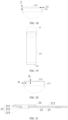
- the first edge portion 2125 protrudes beyond the outer side of the frame 212.
- the first edge portion 2125 may extend along a direction parallel to the X-axis and protrude beyond the outer side of the frame 212, so that the first edge portion 2125 is flush with the opening of the frame 212. When the end cap 211 caps off the opening, the end cap 211 can contact the first edge portion 2125.
- the first edge portion 2125 may extend along a direction at an angle to the X-axis.
- a part of the edge of the end cap 211 may be bent.
- the junction between the end cap 211 and the frame 212 is located outside the frame 212, so that less space is occupied inside the frame 212. In this way, a larger electrode assembly 26 can be accommodated inside the frame 212, thereby increasing the energy density of the battery cell 20.
- the electrode assembly 26 is kept away from the heat source, thereby reducing the risk of damage to the electrode assembly 26 caused by the high temperature.
- FIG. 9 is a schematic diagram of a first edge portion 2125 disposed according to some other embodiments of this application; and FIG. 10 is a close-up view of a part B shown in FIG. 9 .
- the first edge portion 2125 protrudes beyond the inner side of the frame 212.
- the first edge portion 2125 may extend along a direction parallel to the X-axis and protrude beyond the inner side of the frame 212, so that the first edge portion 2125 is flush with the opening of the frame 212.
- the contact area between the end cap 211 and the frame 212 is increased, and the contour of the shell 21 formed by the frame 212 and the two end caps 211 is regular, thereby making it convenient to stack a plurality of battery cells 20 to form a battery 100 pack.
- FIG. 11 is a schematic diagram of a protruding portion 2112 disposed according to some embodiments of this application; and FIG. 12 is a close-up view of a part C shown in FIG. 11 .
- a protruding portion 2112 is disposed on a surface, oriented toward the frame 212, of the end cap 211.
- the protruding portion 2112 is at least partially located in the frame 212 and fits the frame 212 in position.
- the protruding portion 2112 may be a component connected to the surface, oriented toward the frame 212, of the end cap 211.
- the edge of the surface, oriented toward the frame 212, of the end cap 211 may be thinned to form a protruding portion 2112 in at the center of the end cap 211.
- the protruding portion 2112 increases the structural strength of the end cap 211 on the one hand, and plays a role in positioning the end cap 211 on the other hand, thereby making it convenient for the end cap 211 to cap off the opening of the frame 212.
- FIG. 13 is an exploded view of a shell 21 on which a second edge portion 2111 is disposed according to some embodiments of this application; and FIG. 14 is a close-up view of a part D shown in FIG. 13 .
- the second edge portion 2111 is disposed on at least one of the end caps 211.
- the second edge portion 2111 is disposed around an edge of the end cap 211.
- the second edge portion 2111 protrudes beyond a surface, oriented toward the frame 212, of the end cap 211 along the first direction.
- the second edge portion 2111 is configured to be connected to the frame 212.
- the second edge portion 2111 may be a flange connected to the end cap 211, or may be formed by bending the edge of the end cap 211 toward the frame 212.
- the second edge portion 2111 may be continuously arranged around the edge of the end cap 211, or a plurality of second edge portions 2111 may be arranged along the edge of the end cap 211.
- the second edge portion 2111 increases the connection area between the frame 212 and the end cap 211, and in turn, increases the strength of connection between the frame 212 and the end cap 211.
- the second edge portion 2111 plays a role in positioning the end cap 211.
- the interior of the second edge can limit the displacement of the end cap 211 on the XY plane, thereby making it convenient for the end cap 211 to cap off the opening of the frame 212.
- FIG. 15 is a schematic diagram of a fit between end caps 211 and a frame 212 according to some embodiments of this application; and FIG. 16 is a close-up view of a part E shown in FIG. 15 .
- a second edge portion 2111 is disposed on both end caps 211.
- Disposing the second edge portion 2111 on both end caps 211 increases the structural strength of the shell 21 formed by the two end caps 211 and the frame 212.
- the second edge portion 2111 is connected to an outer side of the frame 212.
- the second edge portion 2111 may be disposed around the outer side of the frame 212 to enhance the effect of the second edge portion 2111 in constraining the position of the end cap 211.
- the contour defined by the second edge portion 2111 may be consistent with the contour of the outer side of the frame 212.
- the inner side of the second edge portion 2111 abuts against the outer side of the frame 212.
- at least one second edge portion 2111 may be disposed on each of the two sides of the end cap 211 in the X-axis direction, and at least one second edge portion may be disposed on each of the two sides of the end cap 211 in the Z-axis direction.
- the second edge portion 2111 When the second edge portion 2111 is connected to the outer side of the frame 212, less space is occupied inside the frame 212. In this way, a larger electrode assembly 26 can be accommodated inside the frame 212, thereby increasing the energy density of the battery cell 20.
- the second edge portion 2111 serves a blocking function to prevent high-temperature welding slag generated during welding from entering the shell 21.
- the second edge portion 2111 is connected to an inner side of the frame 212.
- the outer sidewall of the second edge portion 2111 can abut against the inner side of the frame 212, so that the end cap 211 can fit the frame 212 tightly.
- the contour of the shell 21 formed by the frame 212 and the two end caps 211 is regular, thereby making it convenient to stack a plurality of battery cells 20.
- FIG. 17 is a schematic structural diagram of a thickened frame 212 according to some embodiments of this application; and FIG. 18 is a close-up view of a part F shown in FIG. 17 .
- the frame 212 includes an inner side, an outer side, and two end faces. The inner side is disposed opposite to the outer side. The two end faces are disposed opposite to each other along the first direction.
- the two end caps 211 are connected to the two end faces respectively. The end faces are connected to the inner side and the outer side. A distance between the inner side and the outer side is L 1 .
- the end cap 211 includes a connecting portion along the first direction, and the connecting portion overlaps the end face. A thickness of the connecting portion is L 2 , satisfying: L 1 > L 2 .
- the end face forms an opening
- the end cap 211 covers the end face to form a connecting portion, so that the end cap 211 can seal the opening.
- the distance L 1 between the inner side and the outer side reflects an allowed overlap area between the end face and the end cap 211.
- the larger the value of L 1 the larger the area of the end face, and in turn, the larger the contact area between the end cap 211 and the end face.
- FIG. 19 is a schematic diagram of a fit between a frame 212 and end caps 211 according to some embodiments of this application; and FIG. 20 is a close-up view of a part G shown in FIG. 19 .
- the thickness of the end cap 211 is D 1
- the thickness of the frame 212 is D 2 , satisfying: 50 ⁇ m ⁇ D 1 ⁇ 200 ⁇ m; and/or 50 ⁇ m ⁇ D 2 ⁇ 200 ⁇ m.
- D 1 or D 2 is greater than 200 ⁇ m, the thickness of the shell 21 formed by the end caps 211 and the frame 212 is overly large. In this case, when the size of the shell 21 remains constant, the volume of the accommodation space formed by the shell 21 is small, thereby reducing the energy density of the battery cell 20 and increasing the mass of the battery cell 20.
- D 1 or D 2 is less than 50 ⁇ m, the strength of the end cap 211 and the frame 212 is low, and in turn, the strength of the shell 21 is low.
- both D 1 and D 2 are, or, D 1 or D 2 is, greater than or equal to 50 ⁇ m and less than or equal to 200 ⁇ m .
- the thickness D 1 of the end cap 211 satisfies 50 ⁇ m ⁇ D 1 ⁇ 200 ⁇ m
- the strength of the end cap 211 is increased, and at the same time, the internal volume of the shell 21 formed by the end caps 211 and the frame 212 is increased.
- the thickness D 2 of the frame 212 satisfies 50 ⁇ m ⁇ D 1 ⁇ 200 ⁇ m
- the strength of the frame 212 is increased, and at the same time, the internal volume of the shell 21 formed by the end caps 211 and the frame 212 is increased.
- the thickness of the end cap 211 is D 1
- the thickness of the frame 212 is D 2 , satisfying: 70 ⁇ m ⁇ D 1 ⁇ 150 ⁇ m; and/or 70 ⁇ m ⁇ D 2 ⁇ 150 ⁇ m.
- the frame 212 and/or the end cap 211 includes stainless steel.
- both the frame 212 and the end cap 211 include stainless steel, or one of the frame 212 or the end cap 211 includes stainless steel.
- the one that includes stainless steel may be partially made of stainless steel or entirely made of stainless steel.
- the frame 212 may be entirely made of stainless steel or partially made of stainless steel.
- a coating may be applied onto the surface of the stainless steel.
- an insulation layer may be applied onto the surface of the frame 212 and the end cap 211 to electrically insulate the shell 21 from the electrode assembly 26, thereby improving the reliability of the battery cell 20.
- a nickel-plated layer may be disposed on the surface of the frame 212 and the end cap 211. The nickel-plated layer improves the wear resistance and corrosion resistance of the shell 21, and in turn, increases the service life of the shell 21.
- Stainless steel possesses relatively high strength and fatigue strength.
- the stainless steel reduces the wall thickness of the shell 21 formed by the frame 212 and the end caps 211, and enables the shell 21 to accommodate a larger electrode assembly 26, thereby increasing the energy density of the battery cell 20.
- stainless steel is well resistant to corrosion, thereby increasing the service life of the shell 21.
- the frame 212 and/or the end caps 211 may be made of an aluminum alloy.
- the end caps 211 are welded to the frame 212.
- the weld is located at a contact point between the first edge portion 2125 and the end cap 211, or at a contact point between the second edge portion 2111 and the end cap 211.
- the end caps 211 are connected to the frame 212 by welding, thereby achieving the following advantages: on the one hand, the connection strength is high; and, on the other hand, after welding, the contour of the junction between the end cap 211 and the frame 212 is regular without forming a relatively large bulge, thereby making the contour of the shell 21 regular.
- this application further provides a battery cell 20.
- the battery cell includes the shell 21 disclosed in the above embodiment and an electrode assembly 26.
- the electrode assembly 26 is accommodated in the shell 21.
- FIG. 21 is a schematic structural diagram of an electrode terminal 25 according to some embodiments of this application.
- the frame 212 includes a wall portion. A lead-out hole is created on the wall portion. The lead-out hole penetrates the wall portion along a thickness direction of the wall portion.
- the battery cell 20 further includes an electrode terminal 25.
- the electrode terminal 25 is electrically connected to the electrode assembly 26.
- the electrode terminal 25 includes a terminal body 252, a first constraining portion 253, and a second constraining portion 251.
- the terminal body 252 is inserted into the lead-out hole.
- the first constraining portion 253 and the second constraining portion are connected to two ends of the terminal body 252 respectively.
- the first constraining portion 253 and the second constraining portion 251 are located on two sides of the wall portion respectively to fix the terminal body 252.
- the wall portion may be a sidewall of the frame 212. Because the frame 212 includes two openings and a large operating space is available, the lead-out hole is located on the wall portion to facilitate connection of the electrode assembly 26 to the electrode terminal 25.
- the first constraining portion 253 and the second constraining portion 251 may be formed by riveting the terminal body 252 to the wall portion.
- an acting force is applied to both ends of the terminal body 252 along the axial direction of the terminal body 252, so that the terminal body 252 stretches along the radial direction to form the two ends of the terminal body 252.
- the wall portion is partially sandwiched between the first constraining portion 253 and the second constraining portion 251, so that the terminal body 252 can be fixed to the wall portion.
- first constraining portion 253 and the second constraining portion 251 may be independent components.
- a peripheral wall of the terminal body 252 may be provided with threads.
- the first constraining portion 253 and the second constraining portion 251 may be provided with screw holes.
- the terminal body 252 fits the screw holes so that the first constraining portion 253 and the second constraining portion 251 can be threadedly connected to the terminal body 252.
- the terminal body 252 is configured to lead the electrical energy of the electrode assembly 26 out of the shell 21.
- the terminal body 252 is fixed to the wall portion under the action of the first constraining portion 253 and the second constraining portion 251.
- the terminal body 252 does not need to be welded to the wall portion, thereby reducing the risk of weld perforation of the frame 212 and damage to the structure of the frame 212 during welding.
- the battery cell 20 further includes a current collecting component 22.
- the current collecting component 22 connects the electrode terminal 25 to the electrode assembly 26.
- a second lead-out hole is created on the current collecting component 22.
- the terminal body 252 is inserted into the second lead-out hole.
- the first constraining portion 253 is located in the shell 21, and the current collecting component 22 is at least partially located between the first constraining portion 253 and the wall portion.
- the current collecting component 22 is configured to electrically connect the electrode terminal 25 to the electrode assembly 26.
- the current collecting component 22 may be a metallic conductive piece such as a metal wire or a metallic conductive sheet.
- the current collecting component 22 is partially disposed between the first constraining portion 253 and the wall portion, so that the first constraining portion 253 implements connection between the current collecting component 22 and the terminal body 252, and moreover, implements electrical connection between the terminal body 252 and the current collecting component 22, thereby avoiding welding of the terminal body 252 to the current collecting component 22, and reducing the risk of weld perforation of the frame 212 and damage to the structure of the frame 212 during welding.
- the assembling process is streamlined, and the production efficiency is improved.
- the battery cell 20 further includes a first insulator 23.
- the first insulator 23 is at least partially located between the current collecting component 22 and the wall portion along the thickness direction of the wall portion, so as to dielectrically isolate the current collecting component 22 from the wall portion.
- the first insulator 23 may be a sheet made of plastic or rubber.
- a third lead-out hole may be created on the first insulator 23.
- the terminal body 252 is sequentially inserted into the first lead-out hole, the third lead-out hole, and the second lead-out hole sequentially, so that the first insulator 23 can be sandwiched between the wall portion and the current collecting component 22.
- the first insulator 23 By insulating the current collecting component 22 from the wall portion, the first insulator 23 reduces the risk of short-circuiting between the current collecting component and the wall portion, and improves the reliability of the battery cell 20.
- the battery cell 20 further includes a second insulator 24.
- the second insulator 24 is at least partially located between the wall portion and the second constraining portion 251 along the thickness direction of the wall portion.
- the second constraining portion 251 is located outside the shell 21.
- the second insulator 24 may be a sheet made of plastic or rubber.
- a fourth lead-out hole may be created on the second insulator 24.
- the terminal body 252 is inserted into the fourth lead-out hole, so that the second insulator 24 can be partially sandwiched between the second constraining portion 251 and the wall portion.
- a counterbore may be created on a surface of the second insulator 24, where the surface is oriented toward the second constraining portion 251.
- the second constraining portion 251 may be at least partially disposed in the counterbore, so that the second insulator 24 can fit the second constraining portion 251 in position.
- the second insulator 24 By insulating the second constraining portion 251 from the wall portion, the second insulator 24 reduces the risk of short-circuiting between the second constraining portion and the wall portion, and improves the reliability of the battery cell 20.
- this application further provides a battery 100.
- the battery includes the battery cell 20 disclosed in the above embodiment.
- the battery 100 may further include a box 10.
- the battery cell 20 is disposed in the box 10.
- this application further provides an electrical device.
- the electrical device includes the battery 100 disclosed in the above embodiment.
- the battery 100 is configured to provide electrical energy.
- the electrical device may include the battery cell 20 disclosed in the foregoing embodiment.
- the battery cell 20 is configured to provide electrical energy.
- this application further provides a shell 21.
- the shell includes a frame 212 and two end caps 211.
- the frame 212 includes two openings opposite to each other along a first direction. Along the first direction, the two end caps 211 are connected to two ends of the frame 212 respectively, and seal the two openings respectively.
- the two end caps 211 and the frame 212 together define an accommodation space configured to accommodate an electrode assembly 26.
- the frame 212 is a rectangular structure.
- the frame 212 includes a plurality of sidewalls connected sequentially in tandem.
- the plurality of sidewalls close in to form the two openings.
- An area of each of the openings is larger than an area of an outer surface of each of the sidewalls.
Landscapes
- Chemical & Material Sciences (AREA)
- Chemical Kinetics & Catalysis (AREA)
- Electrochemistry (AREA)
- General Chemical & Material Sciences (AREA)
- Engineering & Computer Science (AREA)
- Aviation & Aerospace Engineering (AREA)
- Battery Mounting, Suspending (AREA)
- Sealing Battery Cases Or Jackets (AREA)
Abstract
Description
- This application claims priority to
Chinese Patent Application No. 202222730292.7, filed on October 17, 2022 - This application relates to the technical field of batteries, and in particular, to a shell, a battery cell, a battery, and an electrical device.
- With the development of new energy technology, batteries have been widely used in electrical devices such as electric power carts, electric vehicles, electric aircraft, and electric ships.
- In a production process of battery cells, an encasing step is involved. The encasing is to assemble an electrode assembly into a shell. The existing shell makes it inconvenient to assemble the electrode assembly into the shell, thereby reducing the yield rate of encasing of the electrode assembly. Therefore, how to improve the yield rate of encasing of the electrode assembly is a pressing technical challenge in the production technology of batteries.
- An objective of this application is to provide a shell, a battery cell, a battery, and an electrical device. The shell can improve the yield rate of encasing of the electrode assembly.
- According to a first aspect, an embodiment of this application provides a shell. The shell includes a frame and two end caps. The frame includes two openings opposite to each other along a first direction. The two end caps are connected to two ends of the frame respectively along the first direction, and seal the two openings respectively. The two end caps and the frame together define an accommodation space configured to accommodate an electrode assembly.
- In the above technical solution, two openings are created on the frame, thereby increasing the degree of openness of the frame. On the one hand, this increases the operating space in a process of putting the electrode assembly into the frame, makes it more convenient for the electrode assembly to enter the shell, and improves the yield rate of encasing of the electrode assembly. On the other hand, when the electrode assembly is fitted into the frame from one opening, the encasing status of the electrode assembly can be clearly observed through the other opening, and the position of the electrode assembly can be adjusted, thereby reducing the risk that the electrode assembly is damaged by excessive friction between the electrode assembly and the inner side of the frame during encasing of the electrode assembly, and improving the yield rate of encasing of the electrode assembly.
- In some embodiments, the frame includes a plurality of sidewalls connected sequentially in tandem. The plurality of sidewalls close in to form the two openings. An area of each of the openings is larger than an area of an outer surface of each of the sidewalls.
- In the above technical solution, the area of the opening is larger than the area of the outer surface of each sidewall, the opening is formed on a sidewall with the largest surface area on the shell, thereby making it convenient to put the electrode assembly into the shell.
- In some embodiments, the plurality of sidewalls include a first sidewall, a second sidewall, a third sidewall, and a fourth sidewall connected sequentially in tandem. Along a second direction, the first sidewall is disposed opposite to the third sidewall. Along a third direction, the second sidewall is disposed opposite to the fourth sidewall. The first direction, the second direction, and the third direction are perpendicular to each other.
- In the above technical solution, the first sidewall, the second sidewall, the third sidewall, and the fourth sidewall form a rectangular frame. On the one hand, the rectangular frame makes it convenient to stack a plurality of battery cells to form a battery pack, and improves space utilization. On the other hand, the rectangular frame is simple in structure and facilitates processing and manufacturing.
- In some embodiments, along the first direction, a first edge portion disposed around the opening is disposed at least at one end of the frame. The first edge portion is configured to be connected to the end cap.
- In the above technical solution, the first edge portion increases the contact area between the frame and the end cap, thereby increasing the strength of connection between the frame and the end cap.
- In some embodiments, along the first direction, the first edge portion is disposed at both ends of the frame. The two end caps are connected to the two first edge portions respectively.
- In the above technical solution, the two first edge portions increase the strength of connecting the two end caps to the frame respectively.
- In some embodiments, the first edge portion protrudes beyond an outer side of the frame; or, the first edge portion protrudes beyond an inner side of the frame.
- In the above technical solution, when the first edge portion protrudes beyond the outer side of the frame, the junction between the end cap and the frame is located outside the frame, so that less space is occupied inside the frame. In this way, a larger electrode assembly can be accommodated inside the frame, thereby increasing the energy density of the battery cell. When the first edge portion protrudes beyond the inner side of the frame, the contour of the shell formed by the frame and the two end caps is regular, thereby making it convenient to stack a plurality of battery cells
- In some embodiments, along the first direction, a protruding portion is disposed on a surface, oriented toward the frame, of the end cap. The protruding portion is at least partially located in the frame and fits the frame in position.
- In the above technical solution, the protruding portion increases the structural strength of the end cap on the one hand, and plays a role in positioning the end cap on the other hand, thereby making it convenient for the end cap to cap off the opening of the frame.
- In some embodiments, a second edge portion is disposed on at least one of the end caps. The second edge portion is disposed around an edge of the end cap. The second edge portion protrudes beyond a surface, oriented toward the frame, of the end cap along the first direction. The second edge portion is configured to be connected to the frame.
- In the above technical solution, on the one hand, the second edge portion increases the connection area between the frame and the end cap, and in turn, increases the strength of connection between the frame and the end cap. On the other hand, the second edge portion plays a role in positioning the end cap, and makes it convenient for the end cap to cap off the opening of the frame.
- In some embodiments, the second edge portion is disposed on both of the end caps.
- In the above technical solution, the second edge portion is disposed on both end caps, thereby increasing the structural strength of the shell formed by the two end caps and the frame.
- In some embodiments, the second edge portion is connected to an outer side of the frame; or, the second edge portion is connected to an inner side of the frame.
- In the above technical solution, when the second edge portion is connected to the outer side of the frame, less space is occupied inside the frame. In this way, a larger electrode assembly can be accommodated inside the frame, thereby increasing the energy density of the battery cell. When the second edge portion is connected to the inner side of the frame, the contour of the shell formed by the frame and the two end caps is regular, thereby making it convenient to stack a plurality of battery cells.
- In some embodiments, the frame includes an inner side, an outer side, and two end faces. The inner side is disposed opposite to the outer side. The two end faces are disposed opposite to each other along the first direction. The two end caps are connected to the two end faces respectively. The end faces are connected to the inner side and the outer side. A distance between the inner side and the outer side is L1. The end cap includes a connecting portion along the first direction, and the connecting portion overlaps the end face. A thickness of the connecting portion is L2, satisfying: L1 > L2.
- In the above technical solution, when L1 is greater than L2, on the one hand, the thickness of the frame increases the structural strength of the shell. On the other hand, this increases the contact area of the junction between the end cap and the frame, and increases the strength of connection between the frame and the end cap.
- In some embodiments, a thickness of the end cap is D1, a thickness of the frame is D2, satisfying: 50 µm ≤ D1 ≤ 200 µm; and/or 50 µm ≤ D2 ≤ 200 µm.
- In the above technical solution, when the thickness D1 of the end cap satisfies 50 µm ≤ D1 ≤ 200 µm, the strength of the end cap is increased, and at the same time, the internal volume of the shell formed by the end caps and the frame is increased. When the thickness D2 of the frame satisfies 50 µm ≤ D1 ≤ 200 µm, the strength of the frame is increased, and at the same time, the internal volume of the shell formed by the end caps and the frame is increased.
- In some embodiments, the frame and/or the end cap includes stainless steel.
- In the above technical solution, steel exhibits good physical stability and a good compressive resistance. When the frame and/or the end caps are made of steel, the structural strength of the shell is increased.
- In some embodiments, the end cap is welded to the frame.
- In the above technical solution, the end caps are connected to the frame by welding, thereby achieving the following advantages: on the one hand, the connection strength is high; and, on the other hand, after welding, the contour of the junction between the end cap and the frame is regular without forming a relatively large bulge, thereby making the contour of the shell regular.
- According to a second aspect, an embodiment of this application provides a battery cell. The battery cell includes the shell disclosed in the above embodiment and an electrode assembly. The electrode assembly is accommodated in the shell.
- In some embodiments, the frame includes a wall portion. A lead-out hole is created on the wall portion. The lead-out hole penetrates the wall portion along a thickness direction of the wall portion. The battery cell further includes an electrode terminal, and the electrode terminal is electrically connected to the electrode assembly. The electrode terminal includes a terminal body, a first constraining portion, and a second constraining portion. The terminal body is inserted into the lead-out hole. Along the thickness direction of the wall portion, the first constraining portion and the second constraining portion are connected to two ends of the terminal body respectively. The first constraining portion and the second constraining portion are located on two sides of the wall portion respectively to fix the terminal body.
- In the above technical solution, the terminal body is configured to lead the electrical energy of the electrode assembly out of the shell. The terminal body is fixed to the wall portion under the action of the first constraining portion and the second constraining portion. The terminal body does not need to be welded to the wall portion, thereby reducing the risk of weld perforation of the frame and damage to the structure of the frame during welding.
- In some embodiments, the battery cell further includes a current collecting component. The current collecting component connects the electrode terminal to the electrode assembly. A second lead-out hole is created on the current collecting component. The terminal body is inserted into the second lead-out hole. Along the thickness direction of the wall portion, the first constraining portion is located in the shell, and the current collecting component is at least partially located between the first constraining portion and the wall portion.
- In the above technical solution, the current collecting component is configured to electrically connect the electrode terminal and the electrode assembly. The current collecting component is sandwiched between the first constraining portion and the wall portion to fix the current collecting component to the electrode terminal, thereby streamlining the assembling process and improving the production efficiency.
- According to a third aspect, an embodiment of this application provides a battery. The battery includes the battery cell disclosed in the above embodiment.
- According to a fourth aspect, an embodiment of this application provides an electrical device. The electrical device includes the battery disclosed in the above embodiment.
- The foregoing description is merely an overview of the technical solutions of this application. Some specific embodiments of this application are described below illustratively to enable a clearer understanding of the technical solutions of this application, enable implementation of the technical solutions based on the subject-matter hereof, and make the foregoing and other objectives, features, and advantages of this application more evident and comprehensible.
- By reading the following detailed description of exemplary embodiments, a person of ordinary skill in the art becomes clearly aware of various other advantages and benefits. The drawings are merely intended to illustrate the exemplary embodiments, but not to limit this application. In all the drawings, the same reference numeral represents the same component. In the drawings:
-
FIG. 1 is a schematic structural diagram of a vehicle according to some embodiments of this application; -
FIG. 2 is an exploded view of a battery according to some embodiments of this application; -
FIG. 3 is a schematic structural diagram of a shell according to some embodiments of this application; -
FIG. 4 is an exploded view of a shell according to some embodiments of this application; -
FIG. 5 is a schematic structural diagram of a frame according to some embodiments of this application; -
FIG. 6 is an exploded view of a shell on which a first edge portion is disposed according to some embodiments of this application; -
FIG. 7 is a schematic diagram of a first edge portion disposed according to some embodiments of this application; -
FIG. 8 is a close-up view of a part A shown inFIG. 7 ; -
FIG. 9 is a schematic diagram of a first edge portion disposed according to some other embodiments of this application; -
FIG. 10 is a close-up view of a part B shown inFIG. 9 ; -
FIG. 11 is a schematic diagram of a protruding portion disposed according to some embodiments of this application; -
FIG. 12 is a close-up view of a part C shown inFIG. 11 ; -
FIG. 13 is an exploded view of a shell on which a second edge portion is disposed according to some embodiments of this application; -
FIG. 14 is a close-up view of a part D shown inFIG. 13 ; -
FIG. 15 is a schematic diagram of a fit between end caps and a frame according to some embodiments of this application; -
FIG. 16 is a close-up view of a part E shown inFIG. 15 ; -
FIG. 17 is a schematic structural diagram of a thickened frame according to some embodiments of this application; -
FIG. 18 is a close-up view of a part F shown inFIG. 17 ; -
FIG. 19 is a schematic diagram of a fit between a frame and end caps according to some embodiments of this application; -
FIG. 20 is a close-up view of a part G shown inFIG. 19 ; and -
FIG. 21 is a schematic structural diagram of an electrode terminal according to some embodiments of this application. - List of reference numerals:
10-box; 11-first part; 12-second part; 20-battery cell; 21-shell; 211-end cap; 2111-second edge portion; 2112-protruding portion; 212-frame; 2121-first sidewall; 2122-second sidewall; 2123-third sidewall; 2124-fourth sidewall; 2125-first edge portion; 22-current collecting component; 23-first insulator; 24-second insulator; 25-electrode terminal; 251-second constraining portion; 252-terminal body; 253-first constraining portion; 26-electrode assembly; 100-battery; 200-controller; 300-motor; 1000-vehicle. - Some embodiments of the technical solutions of this application are described in detail below with reference to the drawings. The following embodiments are merely intended as examples to describe the technical solutions of this application more clearly, but not intended to limit the protection scope of this application.
- Unless otherwise defined, all technical and scientific terms used herein bear the same meanings as what is normally understood by a person skilled in the technical field of this application. The terms used herein are merely intended to describe specific embodiments but not to limit this application. The terms "include" and "contain" and any variations thereof used in the specification, claims, and brief description of drawings of this application are intended as non-exclusive inclusion.
- In the description of some embodiments of this application, the technical terms "first" and "second" are merely intended to distinguish between different items but not intended to indicate or imply relative importance or implicitly specify the number of the indicated technical features, specific order, or order of precedence. In the description of some embodiments of this application, unless otherwise expressly specified, "a plurality of" means two or more.
- Reference to an "embodiment" herein means that a specific feature, structure or characteristic described with reference to this embodiment may be included in at least one embodiment of this application. Reference to this term in different places in the specification does not necessarily represent the same embodiment, nor does it represent an independent or alternative embodiment in a mutually exclusive relationship with other embodiments. A person skilled in the art explicitly and implicitly understands that the embodiments described herein may be combined with other embodiments.
- In the description of embodiments of this application, the term "and/or" merely indicates a relationship between related items, and represents three possible relationships. For example, "A and/or B" may represent the following three circumstances: A alone, both A and B, and B alone. In addition, the character "/" herein generally indicates an "or" relationship between the item preceding the character and the item following the character.
- In the description of embodiments of this application, the term "a plurality of" means two or more. Similarly, "a plurality of groups" means two or more groups, and "a plurality of pieces" means two or more pieces.
- In the description of embodiments of this application, a direction or a positional relationship indicated by the terms such as "center", "longitudinal", "transverse", "length", "width", "thickness", "up", "down", "before", "after", "left", "right", "vertical", "horizontal", "top", "bottom", "in", "out", "clockwise", "counterclockwise", "axial", "radial", and "circumferential" is a direction or positional relationship based on the illustration in the drawings, and is merely intended for ease or brevity of description of embodiments of this application, but not intended to indicate or imply that the indicated device or component is necessarily located in the specified direction or constructed or operated in the specified direction. Therefore, such terms are not to be understood as a limitation on embodiments of this application.
- In the description of this application, unless otherwise expressly specified and defined, the technical terms such as "mount", "concatenate", "connect", and "fix" are generic in a broad sense, for example, mean a fixed connection, a detachable connection, or a one-piece configuration; or mean a mechanical connection or an electrical connection; or mean a direct connection or an indirect connection implemented through an intermediary; or mean internal communication between two components or interaction between two components. A person of ordinary skill in the art can understand the specific meanings of the terms in some embodiments of this application according to specific situations.
- In some embodiments of this application, the same reference numeral denotes the same component. For brevity, detailed descriptions of the same component are omitted in a different embodiment. Understandably, dimensions such as thickness, length, and width of various components in some embodiments of this application shown in the drawings, and dimensions such as overall thickness, length, and width of an integrated device are merely illustrative descriptions, but do not constitute any limitation on this application.
- A typical battery cell includes a housing, an electrode assembly, an end cap assembly, and other components. The housing includes an opening. During assembling of the battery cell, the electrode assembly is put into the housing through the opening. The electrode assembly is accommodated in the housing. The end cap caps off the opening of the housing to isolate the internal environment of the battery cell from the external environment.
- The opening is conventionally created on just one of the sidewalls of the housing. Therefore, during encasing of the electrode assembly, on the one hand, it is not convenient to put the electrode assembly into the housing due to the small size of the opening. On the other hand, with just one opening created on the housing, it is not convenient to check whether the electrode assembly is aligned with the opening during the encasing. If the electrode assembly is not aligned with the opening, the electrode assembly rubs against the inner wall of the housing during the encasing, thereby being prone to scratch the outermost separator of the electrode assembly, and posing short-circuit hazards to the battery cell.
- In view of this, a shell is hereby designed. The shell includes a frame and two end caps. The frame includes two openings opposite to each other along a first direction. The two end caps are connected to two ends of the frame respectively along the first direction, and seal the two openings respectively. The two end caps and the frame together define an accommodation space configured to accommodate an electrode assembly.
- Two openings are created on the frame, thereby increasing the degree of openness of the frame. This increases the operating space during encasing of the electrode assembly, makes it more convenient for the electrode assembly to enter the shell, and improves the yield rate of encasing of the electrode assembly.
- An embodiment of this application provides an electrical device powered by a battery. The electrical device may be, but is not limited to, an electric power cart, electric vehicle, ship, spacecraft, or the like. For example, the types of the spacecraft may include an airplane, rocket, space shuttle, spaceship, and the like.
- For ease of description in the following embodiments, a vehicle is used as an example of the electrical device disclosed in an embodiment of this application.
- Referring to
FIG. 1, FIG. 1 is a schematic structural diagram of avehicle 1000 according to some embodiments of this application. Thevehicle 1000 may be an oil-fueled vehicle, a natural gas vehicle, or a new energy vehicle. The new energy vehicle may be a battery electric vehicle, a hybrid electric vehicle, a range-extended electric vehicle, or the like. Abattery 100 is disposed inside thevehicle 1000. Thebattery 100 may be disposed at the bottom, front, or rear of thevehicle 1000. Thebattery 100 may be configured to supply power to thevehicle 1000. For example, thebattery 100 may serve as an operating power supply of thevehicle 1000. Thevehicle 1000 may further include acontroller 200 and amotor 300. Thecontroller 200 is configured to control thebattery 100 to supply power to themotor 300, for example, to meet electrical energy requirements in starting, navigating, or running thevehicle 1000. - In some embodiments of this application, the
battery 100 serves not only as an operating power supply of thevehicle 1000, but may also serve as a driving power supply of thevehicle 1000 to provide driving power for thevehicle 1000 in place of or partly in place of fuel oil or natural gas. - Referring to
FIG. 2, FIG. 2 is an exploded view of abattery 100 according to some embodiments of this application. Thebattery 100 includes abox 10 and abattery cell 20. Thebattery cell 20 is accommodated in thebox 10. Thebox 10 is configured to provide an accommodation space for thebattery cell 20. Thebox 10 may be in various structures. In some embodiments, thebox 10 may include afirst part 11 and asecond part 12. Thefirst part 11 and thesecond part 12 fit and cover each other. Thefirst part 11 and thesecond part 12 together define an accommodation space configured to accommodate thebattery cell 20. Thesecond part 12 may be a hollow structure opened at one end. Thefirst part 11 may be a plate-like structure. Thefirst part 11 fits the opening of thesecond part 12 so that thefirst part 11 and thesecond part 12 together define the accommodation space. Alternatively, both thefirst part 11 and thesecond part 12 may be hollow structures opened at one side. The opening of thefirst part 11 fits the opening of thesecond part 12. Definitely, thebox 10 formed by thefirst part 11 and thesecond part 12 may be in various shapes, such as a cylinder or a cuboid. - The
battery 100 may contain a plurality ofbattery cells 20. The plurality ofbattery cells 20 may be connected in series, parallel, or series-and-parallel pattern. The series-and-parallel pattern means a combination of series connection and parallel connection of the plurality ofbattery cells 20. The plurality ofbattery cells 20 may be directly connected in series, parallel, or series-and-parallel pattern, and then the whole of the plurality ofbattery cells 20 may be accommodated in thebox 10. Alternatively, to make up abattery 100, the plurality ofbattery cells 20 may be connected in series, parallel, or series-and-parallel pattern to form a battery module first, and then a plurality of battery modules are connected in series, parallel, or series-and-parallel pattern to form a whole and accommodated in thebox 10. Thebattery 100 may further include other structures. For example, thebattery 100 may further include a busbar component. The busbar component is configured to implement electrical connection between the plurality ofbattery cells 20. - Each
battery cell 20 may be, but is not limited to, a secondary battery or primary battery; or, may be a lithium-sulfur battery, a sodium-ion battery, or a magnesium-ion battery. - According to some embodiments of this application, referring to
FIG. 3 and FIG. 4, FIG. 3 is a schematic structural diagram of ashell 21 according to some embodiments of this application; andFIG. 4 is an exploded view of ashell 21 according to some embodiments of this application. An embodiment of this application provides ashell 21. The shell includes aframe 212 and twoend caps 211. Theframe 212 includes two openings opposite to each other along a first direction. Along the first direction, the twoend caps 211 are connected to two ends of theframe 212 respectively, and seal the two openings respectively. The twoend caps 211 and theframe 212 together define an accommodation space configured to accommodate anelectrode assembly 26. - The
shell 21 in this embodiment of this application may be configured to accommodate theelectrode assembly 26 of thebattery cell 20. - The first direction may be a direction indicated by the Y-axis in the drawing.
- The
frame 212 may be a structure formed by hollowing out a sheet material, or may be formed by connecting a plurality of sidewalls by welding, bonding or other means. The shape of theframe 212 may be a rectangle, a circle, a triangle, or another polygonal structure. - The
end cap 211 is configured to seal the opening of theframe 212 so that the twoend caps 211 and theframe 212 form a cavity. Theend cap 211 may be a flat plate structure. Theend cap 211 and theframe 212 may be made of the same material or different materials. - The opening is a passage through which the
electrode assembly 26 is put into theshell 21. During use, theelectrode assembly 26 may be fitted into theframe 212 first, and then twoend caps 211 cap off the two openings of theframe 212 respectively to seal theelectrode assembly 26 in theframe 212. - The yield rate of encasing means a ratio of the number of
battery cells 20 in which theelectrode assembly 26 is not damaged to the total number of allbattery cells 20 after theelectrode assembly 26 is fitted into theframe 212. The yield rate of encasing reflects the production quality of thebattery cells 20 in the process of assembling theelectrode assembly 26. The higher the yield rate of encasing, the higher the production quality. - Two openings are created on the
frame 212, thereby increasing the degree of openness of theframe 212. On the one hand, this increases the operating space in a process of putting theelectrode assembly 26 into theframe 212, makes it more convenient to encase theelectrode assembly 26, and improves the yield rate of encasing of theelectrode assembly 26. - On the other hand, when the electrode assembly is fitted into the
frame 212 from one opening, the encasing status of theelectrode assembly 26 can be clearly observed through the other opening, and the position of theelectrode assembly 26 can be adjusted, thereby reducing the risk that the outermost separator of theelectrode assembly 26 is frayed and damaged by excessive friction between the electrode assembly and the inner side of theframe 212 during encasing of theelectrode assembly 26, and improving the yield rate of encasing of theelectrode assembly 26. - Further, after the
electrode assembly 26 is fitted into theframe 212, the production personnel can observe the position of theelectrode assembly 26 in theframe 212 and can adjust the position of theelectrode assembly 26, thereby making it convenient for other components such as thecurrent collecting component 22 and theelectrode terminal 25 of thebattery cell 20 to fit theelectrode assembly 26, and improving the assembling quality of thebattery cell 20. - According to some embodiments of this application, referring to
FIG. 5, FIG. 5 is a schematic structural diagram of aframe 212 according to some embodiments of this application. Theframe 212 includes a plurality of sidewalls connected sequentially in tandem. The plurality of sidewalls close in to form the two openings. An area of each of the openings is larger than an area of an outer surface of each of the sidewalls. - When the plurality of sidewalls are connected sequentially in tandem, two ends, opposite to each other along the first direction, of the sidewalls close in to form two openings.
- The number of sidewalls may be three, four or five, and correspondingly, the
frame 212 is in the shape of a triangle, a rectangle, or a pentagon. - The plurality of sidewalls may be independent of each other. The plurality of sidewalls are connected by welding or bonding to form the
frame 212. Alternatively, the plurality of sidewalls may be formed in one piece. That is, the plurality of sidewalls are formed from a whole plate. For example, when theframe 212 is rectangular, theframe 212 may be formed by bending one plate for three times so that the plate forms four parts. The four parts of the bent plate are connected in tandem. - When the plurality of sidewalls are formed in one piece, a fillet may be formed between the sidewalls in a process of bending the plate, so as to reduce the risk of fracturing the plate when the plate is being bent.
- The area of the opening is an area of a projection of the opening on a reference plane perpendicular to the first direction. When the area of the opening is larger than the area of the outer surface of each sidewall, the opening is formed on a sidewall with the largest surface area on the
shell 21, thereby making it convenient to put theelectrode assembly 26 into theshell 21. In addition, in putting theelectrode assembly 26 into the housing, the movement stroke length of theelectrode assembly 26 relative to the inner wall of theframe 212 is reduced, and the damage of theelectrode assembly 26 caused by friction is reduced. For example, if theframe 212 is a rectangular structure, the accommodation space formed by theshell 21 is cuboidal, and theelectrode assembly 26 may also be cuboidal. It is assumed that the length of the accommodation space is greater than the width and greater than the height of the accommodation space, and the length of theelectrode assembly 26 is also greater than the width and greater than the height of the electrode assembly. In this case, in putting theelectrode assembly 26 into the housing, the largest-area surface of theelectrode assembly 26 may be oriented toward the opening during loading of the electrode assembly into theframe 212, so that the sliding stroke length of theelectrode assembly 26 relative to the inner wall of theframe 212 is the shortest in contrast to a technical solution in which another surface is oriented toward the opening during loading of the electrode assembly into theframe 212. - According to some other embodiments of this application, the
frame 212 may include one sidewall. For example, when theframe 212 is a circular structure, the frame may be formed by curving one plate into a circle and then connecting one end to the other end of the curved plate. - According to some embodiments of this application, referring to
FIG. 5 , the plurality of sidewalls include afirst sidewall 2121, asecond sidewall 2122, athird sidewall 2123, and afourth sidewall 2124 connected sequentially in tandem. Along a second direction, thefirst sidewall 2121 is disposed opposite to thethird sidewall 2123. Along a third direction, thesecond sidewall 2122 is disposed opposite to thefourth sidewall 2124. The first direction, the second direction, and the third direction are perpendicular to each other. - When the first direction is a direction indicated by the Y-axis in the drawing, the second direction may be a direction indicated by the X-axis in the drawing, and the third direction may be a direction indicated by the Z-axis in the drawing.
- When the
first sidewall 2121 is disposed opposite to thethird sidewall 2123 and thesecond sidewall 2122 is disposed opposite to thefourth sidewall 2124, thefirst sidewall 2121, thesecond sidewall 2122, thethird sidewall 2123, and thefourth sidewall 2124 form a rectangular structure. - On the one hand, the
rectangular frame 212 makes it convenient to stack a plurality ofbattery cells 20 to form abattery 100 pack, and improves space utilization. On the other hand, therectangular frame 212 is simple in structure and facilitates processing and manufacturing. - According to some embodiments of this application, referring to
FIG. 6 to FIG. 8 ,FIG. 6 is an exploded view of ashell 21 on which afirst edge portion 2125 is disposed according to some embodiments of this application;FIG. 7 is a schematic diagram of afirst edge portion 2125 disposed according to some embodiments of this application; andFIG. 8 is a close-up view of a part A shown inFIG. 7 . Along the first direction, afirst edge portion 2125 disposed around the opening is disposed at least at one end of theframe 212. Thefirst edge portion 2125 is configured to be connected to theend cap 211. - The
first edge portion 2125 allows the sidewall of theframe 212 to include an out-extending part, so as to increase the contact area between theframe 212 and theend cap 211. Thefirst edge portion 2125 may be a flange connected to the sidewall of theframe 212 to form an opening, or may be a structure protruding beyond the sidewall of theframe 212 and formed by bending a part of the sidewall of theframe 212. - The
first edge portion 2125 may be bonded or welded to theend cap 211. - The
first edge portion 2125 may be continuously arranged around the opening, or a plurality offirst edge portions 2125 may be arranged along the edge of the opening. - The
first edge portion 2125 may be disposed at one end of theframe 212, or thefirst edge portion 2125 may be disposed at both ends of the frame. - The
first edge portion 2125 increases the contact area between theframe 212 and theend cap 211, thereby increasing the strength of connection between theframe 212 and theend cap 211. - According to some embodiments of this application, referring to
FIG. 6 , along the first direction, thefirst edge portion 2125 is disposed at both ends of theframe 212. The twoend caps 211 are connected to the twofirst edge portions 2125 respectively. - The two
first edge portions 2125 increase the contact area between the twoend caps 211 and theframe 212 respectively, thereby increasing the strength of connection between the twoend caps 211 and theframe 212. - According to some embodiments of this application, referring to
FIG. 7 and FIG. 8 , thefirst edge portion 2125 protrudes beyond the outer side of theframe 212. - The
first edge portion 2125 may extend along a direction parallel to the X-axis and protrude beyond the outer side of theframe 212, so that thefirst edge portion 2125 is flush with the opening of theframe 212. When theend cap 211 caps off the opening, theend cap 211 can contact thefirst edge portion 2125. - Alternatively, the
first edge portion 2125 may extend along a direction at an angle to the X-axis. Correspondingly, in order for theend cap 211 to fit thefirst edge portion 2125 when capping off the opening, a part of the edge of theend cap 211 may be bent. - When the
first edge portion 2125 protrudes beyond the outer side of theframe 212, the junction between theend cap 211 and theframe 212 is located outside theframe 212, so that less space is occupied inside theframe 212. In this way, alarger electrode assembly 26 can be accommodated inside theframe 212, thereby increasing the energy density of thebattery cell 20. In addition, when theframe 212 and theend cap 211 are connected in a connection manner that generates high temperature (such as welding), theelectrode assembly 26 is kept away from the heat source, thereby reducing the risk of damage to theelectrode assembly 26 caused by the high temperature. - According to some other embodiments of this application, referring to
FIG. 9 andFIG. 10 ,FIG. 9 is a schematic diagram of afirst edge portion 2125 disposed according to some other embodiments of this application; andFIG. 10 is a close-up view of a part B shown inFIG. 9 . Thefirst edge portion 2125 protrudes beyond the inner side of theframe 212. - The
first edge portion 2125 may extend along a direction parallel to the X-axis and protrude beyond the inner side of theframe 212, so that thefirst edge portion 2125 is flush with the opening of theframe 212. - When the
first edge portion 2125 protrudes beyond the inner side of theframe 212, the contact area between theend cap 211 and theframe 212 is increased, and the contour of theshell 21 formed by theframe 212 and the twoend caps 211 is regular, thereby making it convenient to stack a plurality ofbattery cells 20 to form abattery 100 pack. - According to some embodiments of this application, referring to
FIG. 11 and FIG. 12, FIG. 11 is a schematic diagram of a protrudingportion 2112 disposed according to some embodiments of this application; andFIG. 12 is a close-up view of a part C shown inFIG. 11 . Along the first direction, a protrudingportion 2112 is disposed on a surface, oriented toward theframe 212, of theend cap 211. The protrudingportion 2112 is at least partially located in theframe 212 and fits theframe 212 in position. - The protruding
portion 2112 may be a component connected to the surface, oriented toward theframe 212, of theend cap 211. Alternatively, the edge of the surface, oriented toward theframe 212, of theend cap 211 may be thinned to form a protrudingportion 2112 in at the center of theend cap 211. - The protruding
portion 2112 increases the structural strength of theend cap 211 on the one hand, and plays a role in positioning theend cap 211 on the other hand, thereby making it convenient for theend cap 211 to cap off the opening of theframe 212. - According to some embodiments of this application, referring to
FIG. 13 to FIG. 14, FIG. 13 is an exploded view of ashell 21 on which asecond edge portion 2111 is disposed according to some embodiments of this application; andFIG. 14 is a close-up view of a part D shown inFIG. 13 . Thesecond edge portion 2111 is disposed on at least one of theend caps 211. Thesecond edge portion 2111 is disposed around an edge of theend cap 211. Thesecond edge portion 2111 protrudes beyond a surface, oriented toward theframe 212, of theend cap 211 along the first direction. Thesecond edge portion 2111 is configured to be connected to theframe 212. - The
second edge portion 2111 may be a flange connected to theend cap 211, or may be formed by bending the edge of theend cap 211 toward theframe 212. - The
second edge portion 2111 may be continuously arranged around the edge of theend cap 211, or a plurality ofsecond edge portions 2111 may be arranged along the edge of theend cap 211. - On the one hand, the
second edge portion 2111 increases the connection area between theframe 212 and theend cap 211, and in turn, increases the strength of connection between theframe 212 and theend cap 211. On the other hand, thesecond edge portion 2111 plays a role in positioning theend cap 211. When theend cap 211 caps off the opening, the interior of the second edge can limit the displacement of theend cap 211 on the XY plane, thereby making it convenient for theend cap 211 to cap off the opening of theframe 212. - According to some embodiments of this application, referring to
FIG. 15 to FIG. 16, FIG. 15 is a schematic diagram of a fit betweenend caps 211 and aframe 212 according to some embodiments of this application; andFIG. 16 is a close-up view of a part E shown inFIG. 15 . Asecond edge portion 2111 is disposed on bothend caps 211. - Disposing the
second edge portion 2111 on bothend caps 211 increases the structural strength of theshell 21 formed by the twoend caps 211 and theframe 212. - According to some embodiments of this application, referring to
FIG. 16 , thesecond edge portion 2111 is connected to an outer side of theframe 212. - The
second edge portion 2111 may be disposed around the outer side of theframe 212 to enhance the effect of thesecond edge portion 2111 in constraining the position of theend cap 211. For example, the contour defined by thesecond edge portion 2111 may be consistent with the contour of the outer side of theframe 212. When theend cap 211 caps off the opening of theframe 212, the inner side of thesecond edge portion 2111 abuts against the outer side of theframe 212. For another example, at least onesecond edge portion 2111 may be disposed on each of the two sides of theend cap 211 in the X-axis direction, and at least one second edge portion may be disposed on each of the two sides of theend cap 211 in the Z-axis direction. - When the
second edge portion 2111 is connected to the outer side of theframe 212, less space is occupied inside theframe 212. In this way, alarger electrode assembly 26 can be accommodated inside theframe 212, thereby increasing the energy density of thebattery cell 20. In addition, thesecond edge portion 2111 serves a blocking function to prevent high-temperature welding slag generated during welding from entering theshell 21. - According to some other embodiments of this application, the
second edge portion 2111 is connected to an inner side of theframe 212. - In this embodiment, when the
end cap 211 caps off the opening, the outer sidewall of thesecond edge portion 2111 can abut against the inner side of theframe 212, so that theend cap 211 can fit theframe 212 tightly. - When the
second edge portion 2111 is connected to the inner side of theframe 212, the contour of theshell 21 formed by theframe 212 and the twoend caps 211 is regular, thereby making it convenient to stack a plurality ofbattery cells 20. - According to some embodiments of this application, referring to
FIG. 17 to FIG. 18 ,FIG. 17 is a schematic structural diagram of a thickenedframe 212 according to some embodiments of this application; andFIG. 18 is a close-up view of a part F shown inFIG. 17 . Theframe 212 includes an inner side, an outer side, and two end faces. The inner side is disposed opposite to the outer side. The two end faces are disposed opposite to each other along the first direction. The twoend caps 211 are connected to the two end faces respectively. The end faces are connected to the inner side and the outer side. A distance between the inner side and the outer side is L1. Theend cap 211 includes a connecting portion along the first direction, and the connecting portion overlaps the end face. A thickness of the connecting portion is L2, satisfying: L1 > L2. - The end face forms an opening, and the
end cap 211 covers the end face to form a connecting portion, so that theend cap 211 can seal the opening. - The distance L1 between the inner side and the outer side reflects an allowed overlap area between the end face and the
end cap 211. With the size of theframe 212 being constant, the larger the value of L1, the larger the area of the end face, and in turn, the larger the contact area between theend cap 211 and the end face. - If L1 ≤ L2, the contact area between the
end cap 211 and the end face is overly small, and the structural strength of theshell 21 is reduced. - When L1 is greater than L2, on the one hand, this is equivalent to increasing the thickness of the
frame 212, and in turn, increasing the structural strength of theshell 21. On the other hand, this increases the contact area of the junction between theend cap 211 and theframe 212, increases the strength of connection between theframe 212 and theend cap 211, and reduces the risk of a weld perforation defect during the welding between theend cap 211 and thebox 212. - According to some embodiments of this application, referring to
FIG. 19 to FIG. 20, FIG. 19 is a schematic diagram of a fit between aframe 212 and endcaps 211 according to some embodiments of this application; andFIG. 20 is a close-up view of a part G shown inFIG. 19 . The thickness of theend cap 211 is D1, and the thickness of theframe 212 is D2, satisfying: 50 µm ≤ D1 ≤ 200 µm; and/or 50 µm ≤ D2 ≤ 200 µm. - If D1 or D2 is greater than 200 µm, the thickness of the
shell 21 formed by the end caps 211 and theframe 212 is overly large. In this case, when the size of theshell 21 remains constant, the volume of the accommodation space formed by theshell 21 is small, thereby reducing the energy density of thebattery cell 20 and increasing the mass of thebattery cell 20. - If D1 or D2 is less than 50 µm, the strength of the
end cap 211 and theframe 212 is low, and in turn, the strength of theshell 21 is low. - In this embodiment, both D1 and D2 are, or, D1 or D2 is, greater than or equal to 50 µm and less than or equal to 200 µm .
- When the thickness D1 of the
end cap 211 satisfies 50 µm ≤ D1 ≤ 200 µm, the strength of theend cap 211 is increased, and at the same time, the internal volume of theshell 21 formed by the end caps 211 and theframe 212 is increased. When the thickness D2 of theframe 212 satisfies 50 µm ≤ D1 ≤ 200 µm, the strength of theframe 212 is increased, and at the same time, the internal volume of theshell 21 formed by the end caps 211 and theframe 212 is increased. - In some other embodiments of this application, the thickness of the
end cap 211 is D1, the thickness of theframe 212 is D2, satisfying: 70 µm ≤ D1 ≤ 150 µm; and/or 70 µm ≤ D2 ≤ 150 µm. - According to some embodiments of this application, the
frame 212 and/or theend cap 211 includes stainless steel. - In this embodiments, both the
frame 212 and theend cap 211 include stainless steel, or one of theframe 212 or theend cap 211 includes stainless steel. - Of the
frame 212 and theend cap 211, the one that includes stainless steel may be partially made of stainless steel or entirely made of stainless steel. For example, if theframe 212 includes stainless steel, theframe 212 may be entirely made of stainless steel or partially made of stainless steel. - A coating may be applied onto the surface of the stainless steel. For example, an insulation layer may be applied onto the surface of the
frame 212 and theend cap 211 to electrically insulate theshell 21 from theelectrode assembly 26, thereby improving the reliability of thebattery cell 20. Further, a nickel-plated layer may be disposed on the surface of theframe 212 and theend cap 211. The nickel-plated layer improves the wear resistance and corrosion resistance of theshell 21, and in turn, increases the service life of theshell 21. - Stainless steel possesses relatively high strength and fatigue strength. On the one hand, the stainless steel reduces the wall thickness of the
shell 21 formed by theframe 212 and the end caps 211, and enables theshell 21 to accommodate alarger electrode assembly 26, thereby increasing the energy density of thebattery cell 20. On the other hand, stainless steel is well resistant to corrosion, thereby increasing the service life of theshell 21. - According to some other embodiments of this application, the
frame 212 and/or the end caps 211 may be made of an aluminum alloy. - According to some embodiments of this application, the end caps 211 are welded to the
frame 212. - When the end caps 211 are welded to the
frame 212, the weld is located at a contact point between thefirst edge portion 2125 and theend cap 211, or at a contact point between thesecond edge portion 2111 and theend cap 211. - In the above technical solution, the end caps 211 are connected to the
frame 212 by welding, thereby achieving the following advantages: on the one hand, the connection strength is high; and, on the other hand, after welding, the contour of the junction between theend cap 211 and theframe 212 is regular without forming a relatively large bulge, thereby making the contour of theshell 21 regular. - According to some embodiments of this application, this application further provides a
battery cell 20. The battery cell includes theshell 21 disclosed in the above embodiment and anelectrode assembly 26. Theelectrode assembly 26 is accommodated in theshell 21. - According to some embodiments of this application, referring to
FIG. 21, FIG. 21 is a schematic structural diagram of anelectrode terminal 25 according to some embodiments of this application. Theframe 212 includes a wall portion. A lead-out hole is created on the wall portion. The lead-out hole penetrates the wall portion along a thickness direction of the wall portion. Thebattery cell 20 further includes anelectrode terminal 25. Theelectrode terminal 25 is electrically connected to theelectrode assembly 26. Theelectrode terminal 25 includes aterminal body 252, a first constrainingportion 253, and a second constrainingportion 251. Theterminal body 252 is inserted into the lead-out hole. Along the thickness direction of the wall portion, the first constrainingportion 253 and the second constraining portion are connected to two ends of theterminal body 252 respectively. The first constrainingportion 253 and the second constrainingportion 251 are located on two sides of the wall portion respectively to fix theterminal body 252. - The wall portion may be a sidewall of the
frame 212. Because theframe 212 includes two openings and a large operating space is available, the lead-out hole is located on the wall portion to facilitate connection of theelectrode assembly 26 to theelectrode terminal 25. - The first constraining
portion 253 and the second constrainingportion 251 may be formed by riveting theterminal body 252 to the wall portion. To be specific, an acting force is applied to both ends of theterminal body 252 along the axial direction of theterminal body 252, so that theterminal body 252 stretches along the radial direction to form the two ends of theterminal body 252. The wall portion is partially sandwiched between the first constrainingportion 253 and the second constrainingportion 251, so that theterminal body 252 can be fixed to the wall portion. - Alternatively, the first constraining
portion 253 and the second constrainingportion 251 may be independent components. For example, a peripheral wall of theterminal body 252 may be provided with threads. The first constrainingportion 253 and the second constrainingportion 251 may be provided with screw holes. Theterminal body 252 fits the screw holes so that the first constrainingportion 253 and the second constrainingportion 251 can be threadedly connected to theterminal body 252. - The
terminal body 252 is configured to lead the electrical energy of theelectrode assembly 26 out of theshell 21. Theterminal body 252 is fixed to the wall portion under the action of the first constrainingportion 253 and the second constrainingportion 251. Theterminal body 252 does not need to be welded to the wall portion, thereby reducing the risk of weld perforation of theframe 212 and damage to the structure of theframe 212 during welding. - According to some embodiments of this application, referring to
FIG. 21 , thebattery cell 20 further includes acurrent collecting component 22. Thecurrent collecting component 22 connects theelectrode terminal 25 to theelectrode assembly 26. A second lead-out hole is created on thecurrent collecting component 22. Theterminal body 252 is inserted into the second lead-out hole. Along the thickness direction of the wall portion, the first constrainingportion 253 is located in theshell 21, and thecurrent collecting component 22 is at least partially located between the first constrainingportion 253 and the wall portion. - The
current collecting component 22 is configured to electrically connect theelectrode terminal 25 to theelectrode assembly 26. Thecurrent collecting component 22 may be a metallic conductive piece such as a metal wire or a metallic conductive sheet. - The
current collecting component 22 is partially disposed between the first constrainingportion 253 and the wall portion, so that the first constrainingportion 253 implements connection between thecurrent collecting component 22 and theterminal body 252, and moreover, implements electrical connection between theterminal body 252 and thecurrent collecting component 22, thereby avoiding welding of theterminal body 252 to thecurrent collecting component 22, and reducing the risk of weld perforation of theframe 212 and damage to the structure of theframe 212 during welding. In addition, because no welding is required, the assembling process is streamlined, and the production efficiency is improved. - According to some embodiments of this application, referring to
FIG. 21 , thebattery cell 20 further includes afirst insulator 23. Thefirst insulator 23 is at least partially located between thecurrent collecting component 22 and the wall portion along the thickness direction of the wall portion, so as to dielectrically isolate thecurrent collecting component 22 from the wall portion. - The
first insulator 23 may be a sheet made of plastic or rubber. A third lead-out hole may be created on thefirst insulator 23. Theterminal body 252 is sequentially inserted into the first lead-out hole, the third lead-out hole, and the second lead-out hole sequentially, so that thefirst insulator 23 can be sandwiched between the wall portion and thecurrent collecting component 22. - By insulating the
current collecting component 22 from the wall portion, thefirst insulator 23 reduces the risk of short-circuiting between the current collecting component and the wall portion, and improves the reliability of thebattery cell 20. - According to some embodiments of this application, referring to
FIG. 21 , thebattery cell 20 further includes asecond insulator 24. Thesecond insulator 24 is at least partially located between the wall portion and the second constrainingportion 251 along the thickness direction of the wall portion. The second constrainingportion 251 is located outside theshell 21. - The
second insulator 24 may be a sheet made of plastic or rubber. A fourth lead-out hole may be created on thesecond insulator 24. Theterminal body 252 is inserted into the fourth lead-out hole, so that thesecond insulator 24 can be partially sandwiched between the second constrainingportion 251 and the wall portion. - A counterbore may be created on a surface of the
second insulator 24, where the surface is oriented toward the second constrainingportion 251. The second constrainingportion 251 may be at least partially disposed in the counterbore, so that thesecond insulator 24 can fit the second constrainingportion 251 in position. - By insulating the second constraining
portion 251 from the wall portion, thesecond insulator 24 reduces the risk of short-circuiting between the second constraining portion and the wall portion, and improves the reliability of thebattery cell 20. - According to some embodiments of this application, this application further provides a
battery 100. The battery includes thebattery cell 20 disclosed in the above embodiment. Thebattery 100 may further include abox 10. Thebattery cell 20 is disposed in thebox 10. - According to some embodiments of this application, this application further provides an electrical device. The electrical device includes the
battery 100 disclosed in the above embodiment. Thebattery 100 is configured to provide electrical energy. Alternatively, the electrical device may include thebattery cell 20 disclosed in the foregoing embodiment. Thebattery cell 20 is configured to provide electrical energy. - According to some embodiments of this application, referring to
FIG. 3 to FIG. 5 , this application further provides ashell 21. The shell includes aframe 212 and twoend caps 211. Theframe 212 includes two openings opposite to each other along a first direction. Along the first direction, the twoend caps 211 are connected to two ends of theframe 212 respectively, and seal the two openings respectively. The twoend caps 211 and theframe 212 together define an accommodation space configured to accommodate anelectrode assembly 26. - The
frame 212 is a rectangular structure. Theframe 212 includes a plurality of sidewalls connected sequentially in tandem. The plurality of sidewalls close in to form the two openings. An area of each of the openings is larger than an area of an outer surface of each of the sidewalls. - Finally, it is hereby noted that the foregoing embodiments are merely intended to describe the technical solutions of this application but not to limit this application. Although this application has been described in detail with reference to the foregoing embodiments, a person of ordinary skill in the art understands that modifications may still be made to the technical solutions described in the foregoing embodiments, or equivalent replacements may still be made to some or all technical features in the technical solutions. Such modifications and equivalent replacements fall within the scope of the claims and specification hereof without making the essence of the corresponding technical solutions depart from the scope of the technical solutions of the embodiments of this application. Particularly, to the extent that no structural conflict exists, various technical features mentioned in different embodiments may be combined in any manner. This application is not limited to the specific embodiments disclosed herein, but includes all technical solutions falling within the scope of the claims.
Claims (19)
- A shell, characterized in that the shell comprises:a frame, wherein the frame comprises two openings opposite to each other along a first direction;two end caps, wherein the two end caps are connected to two ends of the frame respectively along the first direction, and seal the two openings respectively, and the two end caps and the frame together define an accommodation space configured to accommodate an electrode assembly.
- The shell according to claim 1, characterized in that the frame comprises a plurality of sidewalls connected sequentially in tandem, the plurality of sidewalls close in to form the two openings, and an area of each of the openings is larger than an area of an outer surface of each of the sidewalls.
- The shell according to claim 2, characterized in that the plurality of sidewalls comprise a first sidewall, a second sidewall, a third sidewall, and a fourth sidewall connected sequentially in tandem;along a second direction, the first sidewall is disposed opposite to the third sidewall;along a third direction, the second sidewall is disposed opposite to the fourth sidewall; andthe first direction, the second direction, and the third direction are perpendicular to each other.
- The shell according to any one of claims 1 to 3, characterized in that, along the first direction, a first edge portion disposed around the opening is disposed at least at one end of the frame, and the first edge portion is configured to be connected to the end cap.
- The shell according to claim 4, wherein, along the first direction, the first edge portion is disposed at both ends of the frame, and the two end caps are connected to the two first edge portions respectively.
- The shell according to claim 4 or 5, characterized in that the first edge portion protrudes beyond an outer side of the frame; or, the first edge portion protrudes beyond an inner side of the frame.
- The shell according to any one of claims 1 to 6, characterized in that, along the first direction, a protruding portion is disposed on a surface, oriented toward the frame, of the end cap, and the protruding portion is at least partially located in the frame and fits the frame in position.
- The shell according to any one of claims 1 to 7, characterized in that a second edge portion is disposed on at least one of the end caps, the second edge portion is disposed around an edge of the end cap, the second edge portion protrudes beyond a surface, oriented toward the frame, of the end cap along the first direction, and the second edge portion is configured to be connected to the frame.
- The shell according to claim 8, characterized in that the second edge portion is disposed on both of the end caps.
- The shell according to claim 8 or 9, characterized in that the second edge portion is connected to an outer side of the frame; or, the second edge portion is connected to an inner side of the frame.
- The shell according to any one of claims 1 to 10, characterized in that the frame comprises an inner side, an outer side, and two end faces; the inner side is disposed opposite to the outer side; the two end faces are disposed opposite to each other along the first direction; the two end caps are connected to the two end faces respectively; and the end faces are connected to the inner side and the outer side; and
a distance between the inner side and the outer side is L1, the end cap comprises a connecting portion along the first direction, the connecting portion overlaps the end face, and a thickness of the connecting portion is L2, satisfying: L1 > L2. - The shell according to any one of claims 1 to 11, characterized in that a thickness of the end cap is D1, a thickness of the frame is D2, satisfying: 50 µm ≤ D1 ≤ 200 µm; and/or 50 µm ≤ D2 ≤ 200 µm.
- The shell according to any one of claims 1 to 11, characterized in that the frame and/or the end cap comprises stainless steel.
- The shell according to any one of claims 1 to 11, characterized in that the end cap is welded to the frame.
- A battery cell, characterized in that the battery cell comprises:the shell according to any one of claims 1 to 14; andan electrode assembly, accommodated in the shell.
- The battery cell according to claim 15, characterized in that the frame comprises a wall portion, a lead-out hole is created on the wall portion, and the lead-out hole penetrates the wall portion along a thickness direction of the wall portion; and
the battery cell further comprises an electrode terminal, and the electrode terminal is electrically connected to the electrode assembly; the electrode terminal comprises a terminal body, a first constraining portion, and a second constraining portion; the terminal body is inserted into the lead-out hole; along the thickness direction of the wall portion, the first constraining portion and the second constraining portion are connected to two ends of the terminal body respectively; and the first constraining portion and the second constraining portion are located on two sides of the wall portion respectively to fix the terminal body. - The battery cell according to claim 16, characterized in that the battery cell further comprises a current collecting component, and the current collecting component connects the electrode terminal to the electrode assembly; and
a second lead-out hole is created on the current collecting component, the terminal body is inserted into the second lead-out hole, and, along the thickness direction of the wall portion, the first constraining portion is located in the shell, and the current collecting component is at least partially located between the first constraining portion and the wall portion. - A battery, characterized in that the battery comprises the battery cell according to any one of claims 15 to 17.
- An electrical device, characterized in that the electrical device comprises the battery according to claim 18.
Applications Claiming Priority (2)
| Application Number | Priority Date | Filing Date | Title |
|---|---|---|---|
| CN202222730292.7U CN218602565U (en) | 2022-10-17 | 2022-10-17 | Shell, battery monomer, battery and consumer |
| PCT/CN2023/124168 WO2024083022A1 (en) | 2022-10-17 | 2023-10-12 | Housing, battery cell, battery and electric device |
Publications (2)
| Publication Number | Publication Date |
|---|---|
| EP4510316A1 true EP4510316A1 (en) | 2025-02-19 |
| EP4510316A4 EP4510316A4 (en) | 2025-11-26 |
Family
ID=85401933
Family Applications (1)
| Application Number | Title | Priority Date | Filing Date |
|---|---|---|---|
| EP23879013.3A Pending EP4510316A4 (en) | 2022-10-17 | 2023-10-12 | HOUSING, BATTERY CELL, BATTERY AND ELECTRICAL DEVICE |
Country Status (6)
| Country | Link |
|---|---|
| US (1) | US20250079574A1 (en) |
| EP (1) | EP4510316A4 (en) |
| JP (1) | JP2025517692A (en) |
| KR (1) | KR20250003772A (en) |
| CN (1) | CN218602565U (en) |
| WO (1) | WO2024083022A1 (en) |
Families Citing this family (2)
| Publication number | Priority date | Publication date | Assignee | Title |
|---|---|---|---|---|
| KR20220161057A (en) * | 2021-05-28 | 2022-12-06 | 주식회사 엘지에너지솔루션 | Battery module and battery pack including the same |
| CN218602565U (en) * | 2022-10-17 | 2023-03-10 | 宁德时代新能源科技股份有限公司 | Shell, battery monomer, battery and consumer |
Family Cites Families (13)
| Publication number | Priority date | Publication date | Assignee | Title |
|---|---|---|---|---|
| JPH10112296A (en) * | 1996-10-07 | 1998-04-28 | Sony Corp | Secondary battery and method of manufacturing the same |
| JPWO2009125544A1 (en) * | 2008-04-11 | 2011-07-28 | 川崎重工業株式会社 | Sealed prismatic battery and battery module using the same |
| JP5364650B2 (en) * | 2010-07-01 | 2013-12-11 | Udトラックス株式会社 | Storage device, connection structure between storage devices, storage module |
| CN206364073U (en) * | 2016-10-25 | 2017-07-28 | 微宏动力系统(湖州)有限公司 | Square housing battery |
| CN111599946A (en) * | 2020-06-18 | 2020-08-28 | 武汉兰钧新能源科技有限公司 | Electric automobile, lithium ion battery and manufacturing method thereof |
| CN216015511U (en) * | 2021-09-27 | 2022-03-11 | 东莞锂微电子科技有限公司 | Secondary battery case and secondary battery |
| CN216648445U (en) * | 2021-10-19 | 2022-05-31 | 惠州锂威新能源科技有限公司 | Battery case, lithium battery and electronic product thereof |
| CN216354451U (en) * | 2021-12-06 | 2022-04-19 | 珠海冠宇电池股份有限公司 | Battery shell and battery |
| CN216435961U (en) * | 2021-12-14 | 2022-05-03 | 珠海冠宇电池股份有限公司 | Battery with a battery cell |
| CN114335828A (en) * | 2021-12-30 | 2022-04-12 | 常州瑞德丰精密技术有限公司 | Battery, electric automobile and preparation method of battery |
| CN114583339A (en) * | 2022-03-11 | 2022-06-03 | 惠州赣锋锂电科技有限公司 | A shell structure with groove and battery |
| CN114552075A (en) * | 2022-03-11 | 2022-05-27 | 惠州赣锋锂电科技有限公司 | Shell structure with inner flange and battery |
| CN218602565U (en) * | 2022-10-17 | 2023-03-10 | 宁德时代新能源科技股份有限公司 | Shell, battery monomer, battery and consumer |
-
2022
- 2022-10-17 CN CN202222730292.7U patent/CN218602565U/en active Active
-
2023
- 2023-10-12 EP EP23879013.3A patent/EP4510316A4/en active Pending
- 2023-10-12 KR KR1020247037470A patent/KR20250003772A/en active Pending
- 2023-10-12 JP JP2024566639A patent/JP2025517692A/en active Pending
- 2023-10-12 WO PCT/CN2023/124168 patent/WO2024083022A1/en not_active Ceased
-
2024
- 2024-11-15 US US18/949,440 patent/US20250079574A1/en active Pending
Also Published As
| Publication number | Publication date |
|---|---|
| US20250079574A1 (en) | 2025-03-06 |
| KR20250003772A (en) | 2025-01-07 |
| WO2024083022A1 (en) | 2024-04-25 |
| CN218602565U (en) | 2023-03-10 |
| EP4510316A4 (en) | 2025-11-26 |
| JP2025517692A (en) | 2025-06-10 |
Similar Documents
| Publication | Publication Date | Title |
|---|---|---|
| US12288840B2 (en) | Cylindrical battery cell, battery, electricity consuming device, manufacturing method and manufacturing system | |
| US20230123940A1 (en) | Battery cell, battery and power consuming device | |
| EP3989352B1 (en) | Secondary battery, battery module, and device using battery as power supply | |
| US12347890B2 (en) | Secondary battery, battery module, and device using secondary battery as power supply | |
| US20250079574A1 (en) | Shell, battery cell, battery, and electrical device | |
| JP2023011675A (en) | Power storage element | |
| CN210743993U (en) | Top cover assembly, secondary battery, battery module, and device | |
| KR102737226B1 (en) | Battery cell, battery, electrical device, method and system for manufacturing battery cell | |
| KR20250027590A (en) | Battery cell, battery, electric device, and manufacturing method and device for battery cell | |
| US20230216077A1 (en) | Spirally wound electrode assembly, battery cell, battery and electric apparatus | |
| US11929510B2 (en) | Secondary battery and manufacturing method thereof, battery module, and apparatus | |
| EP4068490B1 (en) | Battery cell, battery, electric device, and manufacturing method and device for battery cell | |
| EP4601110A1 (en) | Pole piece, battery cell, electrode assembly, battery, and electrical device | |
| KR102912908B1 (en) | Battery cells, batteries, electrical devices, methods and equipment for manufacturing battery cells | |
| US20240047836A1 (en) | Battery cell, battery, electrical device, and device and method for manufacturing battery cell | |
| US20240170809A1 (en) | Tab welding method, welding tool, battery cell, battery, and electric device | |
| EP4738557A1 (en) | Battery cell, battery and electric device | |
| EP4258399A1 (en) | Current collecting member, battery and battery manufacturing method | |
| EP3926751A1 (en) | Current collecting member and manufacturing method therefor, secondary battery and manufacturing method therefor, battery module, and device | |
| EP4009408B1 (en) | Secondary battery and assembled battery | |
| US20250233289A1 (en) | Battery cell, battery, and electric device | |
| US20250158246A1 (en) | Battery cell, battery, and electrical device | |
| US20240039109A1 (en) | Battery housing structure, method for manufacturing same, battery, and electrical device | |
| CN221328042U (en) | Battery cells, batteries, electrical equipment, and battery cell manufacturing equipment | |
| CN218867237U (en) | Shell, battery monomer, battery and consumer |
Legal Events
| Date | Code | Title | Description |
|---|---|---|---|
| STAA | Information on the status of an ep patent application or granted ep patent |
Free format text: STATUS: THE INTERNATIONAL PUBLICATION HAS BEEN MADE |
|
| PUAI | Public reference made under article 153(3) epc to a published international application that has entered the european phase |
Free format text: ORIGINAL CODE: 0009012 |
|
| STAA | Information on the status of an ep patent application or granted ep patent |
Free format text: STATUS: REQUEST FOR EXAMINATION WAS MADE |
|
| 17P | Request for examination filed |
Effective date: 20241115 |
|
| AK | Designated contracting states |
Kind code of ref document: A1 Designated state(s): AL AT BE BG CH CY CZ DE DK EE ES FI FR GB GR HR HU IE IS IT LI LT LU LV MC ME MK MT NL NO PL PT RO RS SE SI SK SM TR |
|
| RAP1 | Party data changed (applicant data changed or rights of an application transferred) |
Owner name: CONTEMPORARY AMPEREX TECHNOLOGY(HONG KONG) LIMITED |
|
| RAP3 | Party data changed (applicant data changed or rights of an application transferred) |
Owner name: CONTEMPORARY AMPEREX TECHNOLOGY(HONG KONG) LIMITED |
|
| A4 | Supplementary search report drawn up and despatched |
Effective date: 20251024 |
|
| RIC1 | Information provided on ipc code assigned before grant |
Ipc: H01M 50/103 20210101AFI20251020BHEP Ipc: H01M 50/15 20210101ALI20251020BHEP Ipc: H01M 50/176 20210101ALI20251020BHEP Ipc: H01M 50/249 20210101ALI20251020BHEP |
|
| DAV | Request for validation of the european patent (deleted) | ||
| DAX | Request for extension of the european patent (deleted) |