EP4510308A2 - Battery pack of vehicle - Google Patents
Battery pack of vehicle Download PDFInfo
- Publication number
- EP4510308A2 EP4510308A2 EP24193775.4A EP24193775A EP4510308A2 EP 4510308 A2 EP4510308 A2 EP 4510308A2 EP 24193775 A EP24193775 A EP 24193775A EP 4510308 A2 EP4510308 A2 EP 4510308A2
- Authority
- EP
- European Patent Office
- Prior art keywords
- battery
- cooling jacket
- cooling
- power conversion
- conversion module
- Prior art date
- Legal status (The legal status is an assumption and is not a legal conclusion. Google has not performed a legal analysis and makes no representation as to the accuracy of the status listed.)
- Pending
Links
Images


Classifications
-
- H—ELECTRICITY
- H01—ELECTRIC ELEMENTS
- H01M—PROCESSES OR MEANS, e.g. BATTERIES, FOR THE DIRECT CONVERSION OF CHEMICAL ENERGY INTO ELECTRICAL ENERGY
- H01M10/00—Secondary cells; Manufacture thereof
- H01M10/60—Heating or cooling; Temperature control
- H01M10/65—Means for temperature control structurally associated with the cells
- H01M10/656—Means for temperature control structurally associated with the cells characterised by the type of heat-exchange fluid
- H01M10/6567—Liquids
- H01M10/6568—Liquids characterised by flow circuits, e.g. loops, located externally to the cells or cell casings
-
- H—ELECTRICITY
- H01—ELECTRIC ELEMENTS
- H01M—PROCESSES OR MEANS, e.g. BATTERIES, FOR THE DIRECT CONVERSION OF CHEMICAL ENERGY INTO ELECTRICAL ENERGY
- H01M10/00—Secondary cells; Manufacture thereof
- H01M10/60—Heating or cooling; Temperature control
- H01M10/61—Types of temperature control
- H01M10/613—Cooling or keeping cold
-
- B—PERFORMING OPERATIONS; TRANSPORTING
- B60—VEHICLES IN GENERAL
- B60L—PROPULSION OF ELECTRICALLY-PROPELLED VEHICLES; SUPPLYING ELECTRIC POWER FOR AUXILIARY EQUIPMENT OF ELECTRICALLY-PROPELLED VEHICLES; ELECTRODYNAMIC BRAKE SYSTEMS FOR VEHICLES IN GENERAL; MAGNETIC SUSPENSION OR LEVITATION FOR VEHICLES; MONITORING OPERATING VARIABLES OF ELECTRICALLY-PROPELLED VEHICLES; ELECTRIC SAFETY DEVICES FOR ELECTRICALLY-PROPELLED VEHICLES
- B60L50/00—Electric propulsion with power supplied within the vehicle
- B60L50/50—Electric propulsion with power supplied within the vehicle using propulsion power supplied by batteries or fuel cells
- B60L50/60—Electric propulsion with power supplied within the vehicle using propulsion power supplied by batteries or fuel cells using power supplied by batteries
- B60L50/64—Constructional details of batteries specially adapted for electric vehicles
-
- H—ELECTRICITY
- H01—ELECTRIC ELEMENTS
- H01M—PROCESSES OR MEANS, e.g. BATTERIES, FOR THE DIRECT CONVERSION OF CHEMICAL ENERGY INTO ELECTRICAL ENERGY
- H01M10/00—Secondary cells; Manufacture thereof
- H01M10/42—Methods or arrangements for servicing or maintenance of secondary cells or secondary half-cells
- H01M10/425—Structural combination with electronic components, e.g. electronic circuits integrated to the outside of the casing
-
- H—ELECTRICITY
- H01—ELECTRIC ELEMENTS
- H01M—PROCESSES OR MEANS, e.g. BATTERIES, FOR THE DIRECT CONVERSION OF CHEMICAL ENERGY INTO ELECTRICAL ENERGY
- H01M10/00—Secondary cells; Manufacture thereof
- H01M10/60—Heating or cooling; Temperature control
- H01M10/62—Heating or cooling; Temperature control specially adapted for specific applications
- H01M10/625—Vehicles
-
- H—ELECTRICITY
- H01—ELECTRIC ELEMENTS
- H01M—PROCESSES OR MEANS, e.g. BATTERIES, FOR THE DIRECT CONVERSION OF CHEMICAL ENERGY INTO ELECTRICAL ENERGY
- H01M10/00—Secondary cells; Manufacture thereof
- H01M10/60—Heating or cooling; Temperature control
- H01M10/65—Means for temperature control structurally associated with the cells
- H01M10/655—Solid structures for heat exchange or heat conduction
- H01M10/6554—Rods or plates
-
- H—ELECTRICITY
- H01—ELECTRIC ELEMENTS
- H01M—PROCESSES OR MEANS, e.g. BATTERIES, FOR THE DIRECT CONVERSION OF CHEMICAL ENERGY INTO ELECTRICAL ENERGY
- H01M10/00—Secondary cells; Manufacture thereof
- H01M10/60—Heating or cooling; Temperature control
- H01M10/65—Means for temperature control structurally associated with the cells
- H01M10/655—Solid structures for heat exchange or heat conduction
- H01M10/6556—Solid parts with flow channel passages or pipes for heat exchange
-
- H—ELECTRICITY
- H01—ELECTRIC ELEMENTS
- H01M—PROCESSES OR MEANS, e.g. BATTERIES, FOR THE DIRECT CONVERSION OF CHEMICAL ENERGY INTO ELECTRICAL ENERGY
- H01M10/00—Secondary cells; Manufacture thereof
- H01M10/60—Heating or cooling; Temperature control
- H01M10/65—Means for temperature control structurally associated with the cells
- H01M10/656—Means for temperature control structurally associated with the cells characterised by the type of heat-exchange fluid
- H01M10/6567—Liquids
-
- H—ELECTRICITY
- H01—ELECTRIC ELEMENTS
- H01M—PROCESSES OR MEANS, e.g. BATTERIES, FOR THE DIRECT CONVERSION OF CHEMICAL ENERGY INTO ELECTRICAL ENERGY
- H01M10/00—Secondary cells; Manufacture thereof
- H01M10/60—Heating or cooling; Temperature control
- H01M10/66—Heat-exchange relationships between the cells and other systems, e.g. central heating systems or fuel cells
- H01M10/667—Heat-exchange relationships between the cells and other systems, e.g. central heating systems or fuel cells the system being an electronic component, e.g. a CPU, an inverter or a capacitor
-
- H—ELECTRICITY
- H01—ELECTRIC ELEMENTS
- H01M—PROCESSES OR MEANS, e.g. BATTERIES, FOR THE DIRECT CONVERSION OF CHEMICAL ENERGY INTO ELECTRICAL ENERGY
- H01M50/00—Constructional details or processes of manufacture of the non-active parts of electrochemical cells other than fuel cells, e.g. hybrid cells
- H01M50/20—Mountings; Secondary casings or frames; Racks, modules or packs; Suspension devices; Shock absorbers; Transport or carrying devices; Holders
- H01M50/204—Racks, modules or packs for multiple batteries or multiple cells
-
- H—ELECTRICITY
- H01—ELECTRIC ELEMENTS
- H01M—PROCESSES OR MEANS, e.g. BATTERIES, FOR THE DIRECT CONVERSION OF CHEMICAL ENERGY INTO ELECTRICAL ENERGY
- H01M50/00—Constructional details or processes of manufacture of the non-active parts of electrochemical cells other than fuel cells, e.g. hybrid cells
- H01M50/50—Current conducting connections for cells or batteries
- H01M50/502—Interconnectors for connecting terminals of adjacent batteries; Interconnectors for connecting cells outside a battery casing
- H01M50/503—Interconnectors for connecting terminals of adjacent batteries; Interconnectors for connecting cells outside a battery casing characterised by the shape of the interconnectors
-
- B—PERFORMING OPERATIONS; TRANSPORTING
- B60—VEHICLES IN GENERAL
- B60L—PROPULSION OF ELECTRICALLY-PROPELLED VEHICLES; SUPPLYING ELECTRIC POWER FOR AUXILIARY EQUIPMENT OF ELECTRICALLY-PROPELLED VEHICLES; ELECTRODYNAMIC BRAKE SYSTEMS FOR VEHICLES IN GENERAL; MAGNETIC SUSPENSION OR LEVITATION FOR VEHICLES; MONITORING OPERATING VARIABLES OF ELECTRICALLY-PROPELLED VEHICLES; ELECTRIC SAFETY DEVICES FOR ELECTRICALLY-PROPELLED VEHICLES
- B60L2210/00—Converter types
- B60L2210/10—DC to DC converters
-
- B—PERFORMING OPERATIONS; TRANSPORTING
- B60—VEHICLES IN GENERAL
- B60L—PROPULSION OF ELECTRICALLY-PROPELLED VEHICLES; SUPPLYING ELECTRIC POWER FOR AUXILIARY EQUIPMENT OF ELECTRICALLY-PROPELLED VEHICLES; ELECTRODYNAMIC BRAKE SYSTEMS FOR VEHICLES IN GENERAL; MAGNETIC SUSPENSION OR LEVITATION FOR VEHICLES; MONITORING OPERATING VARIABLES OF ELECTRICALLY-PROPELLED VEHICLES; ELECTRIC SAFETY DEVICES FOR ELECTRICALLY-PROPELLED VEHICLES
- B60L2210/00—Converter types
- B60L2210/40—DC to AC converters
-
- H—ELECTRICITY
- H01—ELECTRIC ELEMENTS
- H01M—PROCESSES OR MEANS, e.g. BATTERIES, FOR THE DIRECT CONVERSION OF CHEMICAL ENERGY INTO ELECTRICAL ENERGY
- H01M2220/00—Batteries for particular applications
- H01M2220/20—Batteries in motive systems, e.g. vehicle, ship, plane
-
- Y—GENERAL TAGGING OF NEW TECHNOLOGICAL DEVELOPMENTS; GENERAL TAGGING OF CROSS-SECTIONAL TECHNOLOGIES SPANNING OVER SEVERAL SECTIONS OF THE IPC; TECHNICAL SUBJECTS COVERED BY FORMER USPC CROSS-REFERENCE ART COLLECTIONS [XRACs] AND DIGESTS
- Y02—TECHNOLOGIES OR APPLICATIONS FOR MITIGATION OR ADAPTATION AGAINST CLIMATE CHANGE
- Y02E—REDUCTION OF GREENHOUSE GAS [GHG] EMISSIONS, RELATED TO ENERGY GENERATION, TRANSMISSION OR DISTRIBUTION
- Y02E60/00—Enabling technologies; Technologies with a potential or indirect contribution to GHG emissions mitigation
- Y02E60/10—Energy storage using batteries
Definitions
- the present disclosure relates to a battery pack for a vehicle.
- an eco-friendly vehicle may include a battery pack equipped with a plurality of batteries, a power conversion module (e.g., an inverter or a converter), and the like.
- the battery pack and the power conversion module may occupy a separate space, respectively, and a cooling device for providing a coolant to each thereof may be also installed separately, and components for connecting them may be configured very complexly.
- cooling of both the battery and the power conversion module may be required when driving the eco-friendly vehicle, but cooling of the power conversion module may not be required when charging the battery. Therefore, if cooling capability of the power conversion module can be converted to cooling capability of the battery during charging the battery, the cooling of the battery may be focused upon, thus a charging speed may increase and stability may be secured.
- cooling devices may be installed for a battery pack and a power conversion module, respectively, and each of the cooling devices may operate independently. Accordingly, the cooling of the battery may not be focused on, and the charging speed may not increase and stability may not be secured during charging the battery.
- An aspect of the present disclosure is to provide a battery pack for a vehicle capable of improving cooling performance of a battery and a power conversion module.
- An aspect of the present disclosure is to provide a battery pack for a vehicle capable of simplifying a cooling structure and focusing on cooling of a battery during charging of the battery, to secure a charging speed and stability while reducing costs.
- An aspect of the present disclosure is to provide a battery pack for a vehicle capable of differentially controlling cooling performance of a power conversion module and a battery.
- a battery pack for a vehicle includes a plurality of battery modules; and a first cooling jacket having a flow path formed therein through which a cooling medium flows, wherein each of the plurality of battery modules includes a battery; and a power conversion module converting power of the battery, wherein the power conversion module is in close contact with one surface of the first cooling jacket, and the battery is in close contact with the other surface of the first cooling jacket.
- the battery pack may further include a second cooling jacket in close contact with lower surfaces of the plurality of battery modules and having a flow path formed therein through which a cooling medium flows.
- the battery and the first cooling jacket, the first cooling jacket and the power conversion module, and the second cooling jacket and the plurality of battery modules may be in close contact with each other through a heat transfer medium.
- a flow rate of the cooling medium flowing through the flow path formed in the second cooling jacket and a flow rate of a cooling medium flowing through the flow path formed in the first cooling jacket may be independently adjustable.
- each of the plurality of battery modules may further include a busbar connecting the battery and the power conversion module, and the first cooling jacket may have at least one opening through which the busbar passes.
- the busbar may have one side fastened to the battery through the opening, and the other side fastened to the power conversion module through the opening.
- the busbar may have a ' ' shape.
- the first cooling jacket may be formed as a single cooling jacket, or in a form in which a plurality of cooling jackets are connected.
- the power conversion module may include at least one of a DC/DC converter or a DC/AC inverter.
- a battery pack for a vehicle includes a plurality of battery modules, a first cooling jacket having a flow path formed therein through which a cooling medium flows, and a second cooling jacket having a flow path formed therein through which a cooling medium flows, wherein each of the plurality of battery modules includes a battery; a power conversion module converting power of the battery; and a busbar connecting the battery and the power conversion module, wherein the power conversion module is in close contact with one surface of the first cooling jacket, and the battery is in close contact with the other surface of the first cooling jacket, and the plurality of battery modules are in close contact with an upper surface of the second cooling jacket.
- the terms “comprise,” “include,” “have,” or the like when used in the present specification, specify the presence of stated features, integers, steps, operations, elements, components or a combination thereof, but do not preclude the presence or addition of one or more other features, integers, steps, operations, elements, components, and/or groups thereof.
- FIG. 1 is a perspective view of a battery pack for a vehicle according to an embodiment of the present disclosure.
- FIG. 2A is a view of the battery pack illustrated in FIG. 1 from the top
- FIG. 2B is a cross-sectional view of the battery pack illustrated in FIG. 1 from the side.
- a battery pack 100 of a vehicle may include a plurality of battery modules 110a, 110b, 110c, 110d, 110e, 110f, 110g, 110h, 110i, 110j, 110k, and 1101, a first cooling jacket 300, and a second cooling jacket 200.
- FIG. 1 illustrates 12 battery modules, this is illustrative to assist understanding of the present disclosure, and the number thereof may be at least two or more.
- the plurality of battery modules 110a, 110b, 110c, 110d, 110e, 110f, 110g, 110h, 110i, 110j, 110k, and 1101 may include three single-phase battery systems 100-1, 100-2, and 100-3.
- the three single-phase battery systems 100-1, 100-2, and 100-3 may include AC system output terminals of three-phase (A-phase, B-phase, C-phase) configured by serially connecting inverter output terminals (see 413 and 414 of FIG. 5 described later) through a busbar 115.
- the AC system output terminals of the three-phase (A-phase, B-phase, C-phase) may output different AC voltages having the same magnitude and the same phase difference.
- the AC system output terminals of the three phases may output different AC voltages with a phase difference of 120 degrees from each other. Therefore, the AC system output terminals of the three phases (A phase, B phase, C phase) may output three-phase AC voltages, and may provide a driving voltage to a motor using the three-phase AC voltage as the driving voltage.
- the busbar 115 described above may be provided on a side surface of the battery module, and may be installed away from the first cooling jacket 300, not to contact the first cooling jacket 300, thereby allowing cooling by air cooling, but is not necessarily limited thereto. It is possible to configure the busbar 115 to come into contact with the first cooling jacket 300.
- the plurality of battery modules 110a, 110b, 110c, 110d, 110e, 110f, 110g, 110h, 110i, 110j, 110k, and 110l may have the same structure.
- structures thereof will be described with reference to FIGS. 1 to 2B , focusing on a battery module 110a.
- the battery module 110a may include a battery 111, a power conversion module 112 converting power of the battery 111, and a busbar 113.
- the second cooling jacket 200 may be in close contact with a lower surface of the battery module (110a, 110b, 110c, 110d, 110e, 110f, 110g, 110h, 110i, 110j, 110k, and 1101), and a flow path may be formed therein through which a cooling medium flows.
- the cooling medium may be introduced through an inlet 200a, circulated across an entire second cooling jacket 200 along the flow path formed therein, and then discharged through an outlet 200b.
- the cooling medium may be a coolant, but other cooling mediums may also be applied in addition to the coolant.
- the battery 111 may be in close contact with one surface of the first cooling jacket 300, the power conversion module 112 may be in close contact with the other surface of the first cooling jacket 300, and a flow path 300c through which the cooling medium flows may be formed in the first cooling jacket 300.
- the drawing illustrates that the battery 111 is in close contact with a lower surface of the first cooling jacket 300, and the power conversion module 112 is in close contact with an upper surface of the cooling jacket 300, it can be understood that, depending on an embodiment, the battery 111 may be in close contact with the upper surface of the cooling jacket 300, and the power conversion module 112 may be in close contact with the lower surface of the cooling jacket 300.
- the cooling medium may be introduced through an inlet 300a, circulated across an entire first cooling jacket 300 along the flow path formed therein, and then discharged through an outlet 300b.
- thermal resistance between the first cooling jacket 300 and the battery 111 may be smaller than thermal resistance between the first cooling jacket 300 and the power conversion module 112.
- a distance between the flow path formed in the first cooling jacket and the battery may be configured to be shorter than a distance between the flow path formed in the first cooling jacket and the power conversion module, or an area of a flow path adjacent to the power conversion module, among the flow paths formed in the first cooling jacket, may be configured to be smaller than an area of a flow path adjacent to the battery (see FIGS. 3A and 3B below).
- FIGS. 3A and 3B are views illustrating a flow path in a first cooling jacket according to an embodiment of the present disclosure.
- a distance L1 between a flow path 300c formed in a first cooling jacket 300 and a battery 111 may be shorter than a distance L2 between the flow path 300c formed in the first cooling jacket 300 and a power conversion module 112.
- an area A1 of a flow path adjacent to the power conversion module 112 may be smaller than an area A2 of a flow path adjacent to the battery 111.
- thermal resistance of a heat transfer medium 114b provided between the first cooling jacket 300 and the battery 111 may be smaller than thermal resistance of a heat transfer medium 114c provided between the first cooling jacket 300 and the power conversion module 112.
- cooling performance of the power conversion module and the battery may be differentially controlled.
- the first cooling jacket 300 may be provided with at least one opening 300d through which the busbar 113 passes, and the busbar 113 may be connected to the battery 111 and the power conversion module 112 through the opening 300d.
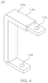
- FIG. 4 is a view illustrating a busbar according to an embodiment of the present disclosure.
- a busbar 113 may include a conductor 113a such as copper, and an insulating medium 113b (e.g., an insulating coating or an insulating paper) for insulating the conductor 113a.
- a conductor 113a such as copper
- an insulating medium 113b e.g., an insulating coating or an insulating paper
- One side of the busbar 113 may be screw-fastened to a battery 111 through a groove 113c, and the other side of the busbar 113 may be screw-fastened to a power conversion module 112 through a groove 113d.
- This busbar 113 may have a ' ' shape.
- a second cooling jacket 200 and a plurality of battery modules 110a, 110b, 110c, 110d, 110e, 110f, 110g, 110h, 110i, 110j, 110k, and 110l, the battery 111 and a first cooling jacket 300, and the first cooling jacket 300 and the power conversion module 112 may be in close contact with each other via heat transfer media 114a, 114b, and 114c, respectively.
- the heat transfer media 114a, 114b, and 114c may be provided as thermal grease or heat transfer pads.
- a flow rate of a cooling medium flowing through a flow path formed in the second cooling jacket 200 and a flow rate of a cooling medium flowing through a flow path formed in the first cooling jacket 300 may be independently adjustable.
- a valve or a water pump (not illustrated separately) may be installed in an inlet 200a of the second cooling jacket 200 and an inlet 300a of the first cooling jacket 300, respectively, to independently control the flow rates of the cooling media.
- the power conversion module 112 may be a device for converting power of the battery 111, and may include at least one of a DC/DC converter or a DC/AC inverter.
- FIG. 5 is a view illustrating a circuit of a battery module according to an embodiment of the present disclosure. It should be noted that the circuit illustrated in FIG. 5 may be intended to assist understanding of the present disclosure, and the present disclosure is not limited to FIG. 5 .
- a battery module 110 may include a battery 111, an inverter 410 connected to the battery 111, a first DC/DC converter 420, and a second DC/DC converter 430.
- a common capacitor 440 may be further included.
- the inverter 410, the first DC/DC converter 420, and the second DC/DC converter 430 may correspond to a power conversion module of the present disclosure.
- the battery 111 may output a battery voltage and may charge or discharge electric energy.
- the battery voltage may form a base voltage of the battery module 110 to provide an input voltage of the inverter 410, an input voltage of the first DC/DC converter 420, and an input voltage of the second DC/DC converter 430.
- the battery 111 may have a battery voltage of a lower magnitude than a high-voltage battery pack applied to a conventional electric vehicle driving system. Therefore, a battery module 110 for a vehicle according to an embodiment of the present disclosure may apply a power conversion element that may operate at low voltage, to reduce manufacturing costs.
- a battery module 110 since various sizes and types of voltages may be output depending on a series/parallel combination of the battery modules 110, there may be advantages of being applicable to various vehicle models of specifications using a battery module 110 of a single standard, and reducing manufacturing costs.
- a battery system outputting a voltage of 400 V may be formed by connecting four battery modules 110 in series, and a battery system outputting a voltage of 800 V may be formed by combining eight battery modules 110 in series.
- a battery system outputting a voltage of 400 V may be formed by connecting 8 battery modules 110 in series, and a battery system outputting a voltage of 800 V may be formed by connecting 16 battery modules 110 in series.
- a single-phase battery system outputting a high-voltage AC voltage may be formed by connecting battery modules 110 in series and using an output of an inverter, and a three-phase AC voltage may be output by using the single-phase battery system in plural.
- a battery system in which a large current flows may be formed by combining battery modules 110 in parallel.
- the inverter 410 may convert the battery voltage into an AC module voltage, and may output the same.
- the inverter 410 may include input terminals 411 and 412 and output terminals 413 and 414, and the input terminals 411 and 412 of the inverter may be connected in parallel to the battery 111 to receive the battery voltage, and the output terminals 413 and 414 of the inverter may output the AC module voltage.
- the output terminals 413 and 414 of the inverter may be referred to as an AC module output terminal that outputs the AC module voltage.
- the first DC/DC converter 420 may convert the battery voltage into a first DC module voltage, lower than the battery voltage, and may output the same.
- the first DC module voltage may be set as a driving voltage of a low-voltage load.
- the low-voltage load may be an electric load such as various lamps, a radio, an infotainment, or the like of an electric vehicle.
- the first DC module voltage may be set to 12V, 24V, or 48V, which may be the driving voltage of the low-voltage load.
- a magnitude of the voltage mentioned in the present specification may be only an embodiment, and may be set to voltages of various magnitudes depending on the design.
- the first DC/DC converter 420 may include input terminals 421 and 422 and output terminals 423 and 424, and the input terminals 421 and 422 of the first DC/DC converter 420 may be connected in parallel to the battery 111 to receive the battery voltage, and the output terminals 423 and 424 of the first DC/DC converter 420 may output the first DC module voltage.
- the output terminals 423 and 424 of the first DC/DC converter 420 may also be referred to as a first DC module output terminal outputting the first DC module voltage.
- the output terminals 423 and 424 of the first DC/DC converter 420 may be directly connected to the low-voltage load to provide the first DC module voltage.
- one end (424) may be grounded, and the other end (423) may be connected to the low-voltage load to output the first DC module voltage.
- both ends of the output terminal of the first DC/DC converter 420 may be connected to both ends of the low-voltage load to output the first DC module voltage.
- the second DC/DC converter 430 may convert the battery voltage into a second DC module voltage, and may output the same.
- the second DC module voltage may be set to a higher value than the first DC module voltage output from the first DC/DC converter 420.
- the second DC module voltage may be less than or equal to the battery voltage, and may be greater than the battery voltage.
- the second DC module voltage output from the second DC/DC converter 430 may be connected in series with the second DC module voltage output from a different battery module 110, to provide power to a high-voltage load.
- the second DC module voltage output from the second DC/DC converter 430 may not provide power to the high-voltage load as a single output, but may be connected in series with the second DC module voltage of a different battery module 110, to provide power to a high-voltage load.
- the battery voltage included in the battery module 110 is configured as a low voltage, to provide a voltage to the high-voltage load such as an air conditioning system or the like, a plurality of battery modules 110 may be combined in series to provide a high voltage.
- an output terminal of the second DC/DC converter 430 may be connected in series with an output terminal of the second DC/DC converter 430 of a different battery module, to form a high voltage and provide power to a high-voltage load.
- the second DC/DC converter 430 may include input terminals 431 and 432 and output terminals 433 and 434, and the input terminals 431 and 432 of the second DC/DC converter 430 may be connected in parallel with the battery 111 to receive the battery voltage, and the output terminals 433 and 434 of the second DC/DC converter 430 may output the second DC module voltage.
- the output terminals 433 and 434 of the second DC/DC converter 430 in the present specification may also be referred to as a second DC module output terminal outputting the second DC module voltage.
- the output terminals 433 and 434 of the second DC/DC converter 430 may be connected in series with output terminals of a second DC/DC converter 430 included in a different battery module, or may be connected to the high-voltage load.
- the battery 111 may be configured to be connected in parallel with the input terminals 411 and 412 of the inverter 410, the input terminals 421 and 422 of the first DC/DC converter 420, and the input terminals 431 and 432 of the second DC/DC converter 430.
- the common capacitor 440 may be connected in parallel with the battery 111, and may be configured to be connected in parallel with the input terminals 411 and 412 of the inverter, the input terminals 421 and 422 of the first DC/DC converter, and the input terminals 431 and 432 of the second DC/DC converter.
- a battery module 110 since one common capacitor may be shared without applying individual capacitors to an inverter and a converter, respectively, there may be an advantage of reducing a volume, and since a low-voltage capacitor may be applied, there may be an advantage of reducing production costs.
- a first cooling jacket may be added in a battery pack, and a power conversion module and a battery may be in close contact with one surface and the other surface of the first cooling jacket, respectively, to improve cooling performance of the battery and the power conversion module.
- power conversion modules such as an inverter and a converter may be gathered in a battery pack, and a cooling jacket may be disposed in the battery pack for cooling them, to simplify a cooling structure and focus on cooling of a battery during charging the battery, to secure a charging speed and stability while reducing costs.
- thermal resistance between a first cooling jacket and a battery may be configured to be smaller than thermal resistance between the first cooling jacket and the power conversion module, or a flow rate of a cooling medium flowing through a flow path formed in a second cooling jacket and a flow rate of a cooling medium flowing through a flow path formed in the first cooling jacket may be independently adjustable, to allow cooling performance of the power conversion module and the battery to be differentially controlled.
Landscapes
- Engineering & Computer Science (AREA)
- Chemical & Material Sciences (AREA)
- Chemical Kinetics & Catalysis (AREA)
- Electrochemistry (AREA)
- General Chemical & Material Sciences (AREA)
- Manufacturing & Machinery (AREA)
- Sustainable Development (AREA)
- Life Sciences & Earth Sciences (AREA)
- Microelectronics & Electronic Packaging (AREA)
- Sustainable Energy (AREA)
- Power Engineering (AREA)
- Transportation (AREA)
- Mechanical Engineering (AREA)
- Secondary Cells (AREA)
- Battery Mounting, Suspending (AREA)
- Electric Propulsion And Braking For Vehicles (AREA)
Abstract
Description
- The present disclosure relates to a battery pack for a vehicle.
- Generally, an eco-friendly vehicle may include a battery pack equipped with a plurality of batteries, a power conversion module (e.g., an inverter or a converter), and the like. The battery pack and the power conversion module may occupy a separate space, respectively, and a cooling device for providing a coolant to each thereof may be also installed separately, and components for connecting them may be configured very complexly.
- In addition, cooling of both the battery and the power conversion module may be required when driving the eco-friendly vehicle, but cooling of the power conversion module may not be required when charging the battery. Therefore, if cooling capability of the power conversion module can be converted to cooling capability of the battery during charging the battery, the cooling of the battery may be focused upon, thus a charging speed may increase and stability may be secured.
- However, in a structure of the existing cooling device, cooling devices may be installed for a battery pack and a power conversion module, respectively, and each of the cooling devices may operate independently. Accordingly, the cooling of the battery may not be focused on, and the charging speed may not increase and stability may not be secured during charging the battery.
- An aspect of the present disclosure is to provide a battery pack for a vehicle capable of improving cooling performance of a battery and a power conversion module.
- An aspect of the present disclosure is to provide a battery pack for a vehicle capable of simplifying a cooling structure and focusing on cooling of a battery during charging of the battery, to secure a charging speed and stability while reducing costs.
- An aspect of the present disclosure is to provide a battery pack for a vehicle capable of differentially controlling cooling performance of a power conversion module and a battery.
- According to an aspect of the present disclosure, a battery pack for a vehicle includes a plurality of battery modules; and a first cooling jacket having a flow path formed therein through which a cooling medium flows, wherein each of the plurality of battery modules includes a battery; and a power conversion module converting power of the battery, wherein the power conversion module is in close contact with one surface of the first cooling jacket, and the battery is in close contact with the other surface of the first cooling jacket.
- According to an embodiment of the present disclosure, the battery pack may further include a second cooling jacket in close contact with lower surfaces of the plurality of battery modules and having a flow path formed therein through which a cooling medium flows.
- According to an embodiment of the present disclosure, the battery and the first cooling jacket, the first cooling jacket and the power conversion module, and the second cooling jacket and the plurality of battery modules may be in close contact with each other through a heat transfer medium.
- According to an embodiment of the present disclosure, a flow rate of the cooling medium flowing through the flow path formed in the second cooling jacket and a flow rate of a cooling medium flowing through the flow path formed in the first cooling jacket may be independently adjustable.
- According to an embodiment of the present disclosure, each of the plurality of battery modules may further include a busbar connecting the battery and the power conversion module, and the first cooling jacket may have at least one opening through which the busbar passes.
- According to an embodiment of the present disclosure, the busbar may have one side fastened to the battery through the opening, and the other side fastened to the power conversion module through the opening.
- According to an embodiment of the present disclosure, the busbar may have a '' shape.

- According to an embodiment of the present disclosure, the first cooling jacket may be formed as a single cooling jacket, or in a form in which a plurality of cooling jackets are connected.
- According to an embodiment of the present disclosure, the power conversion module may include at least one of a DC/DC converter or a DC/AC inverter.
- According to another aspect of the present disclosure, a battery pack for a vehicle includes a plurality of battery modules, a first cooling jacket having a flow path formed therein through which a cooling medium flows, and a second cooling jacket having a flow path formed therein through which a cooling medium flows, wherein each of the plurality of battery modules includes a battery; a power conversion module converting power of the battery; and a busbar connecting the battery and the power conversion module, wherein the power conversion module is in close contact with one surface of the first cooling jacket, and the battery is in close contact with the other surface of the first cooling jacket, and the plurality of battery modules are in close contact with an upper surface of the second cooling jacket.
- The above and other aspects, features, and advantages of the present disclosure will be more clearly understood from the following detailed description, taken in conjunction with the accompanying drawings, in which:
-
FIG. 1 is a perspective view of a battery pack for a vehicle according to an embodiment of the present disclosure. -
FIG. 2A is a view of the battery pack illustrated inFIG. 1 from the top. -
FIG. 2B is a cross-sectional view of the battery pack illustrated inFIG. 1 from the side. -
FIGS. 3A and3B are views illustrating a flow path in a first cooling jacket according to an embodiment of the present disclosure. -
FIG. 4 is a view illustrating a busbar according to an embodiment of the present disclosure. -
FIG. 5 is a view illustrating a circuit of a battery module according to an embodiment of the present disclosure. - Hereinafter, specific embodiments of the present disclosure will be described with reference to the accompanying drawings. The following detailed description is provided to aid in a comprehensive understanding of a method, a device and/or a system described in the present specification. However, the detailed description is for illustrative purposes only, and the present disclosure is not limited thereto.
- In describing the embodiments of the present disclosure, when it is determined that a detailed description of a known technology related to the present disclosure may unnecessarily obscure the gist of the present disclosure, a detailed description thereof will be omitted. In addition, terms to be described later are terms defined in consideration of functions in the present disclosure, which may vary depending on intention or custom of a user or operator. Therefore, the definition of these terms should be made based on the contents throughout the present specification. The terminology used herein is for the purpose of describing particular embodiments only and is not to be limiting of the embodiments. As used herein, the singular forms are intended to include the plural forms as well, unless the context clearly indicates otherwise. As used herein, the terms "comprise," "include," "have," or the like, when used in the present specification, specify the presence of stated features, integers, steps, operations, elements, components or a combination thereof, but do not preclude the presence or addition of one or more other features, integers, steps, operations, elements, components, and/or groups thereof.
-
FIG. 1 is a perspective view of a battery pack for a vehicle according to an embodiment of the present disclosure.FIG. 2A is a view of the battery pack illustrated inFIG. 1 from the top, andFIG. 2B is a cross-sectional view of the battery pack illustrated inFIG. 1 from the side. - As illustrated in
FIGS. 1 to 2B , abattery pack 100 of a vehicle according to an embodiment of the present disclosure may include a plurality ofbattery modules first cooling jacket 300, and asecond cooling jacket 200. AlthoughFIG. 1 illustrates 12 battery modules, this is illustrative to assist understanding of the present disclosure, and the number thereof may be at least two or more. - The plurality of
battery modules FIG. 5 described later) through abusbar 115. The AC system output terminals of the three-phase (A-phase, B-phase, C-phase) may output different AC voltages having the same magnitude and the same phase difference. - For example, the AC system output terminals of the three phases (A phase, B phase, C phase) may output different AC voltages with a phase difference of 120 degrees from each other. Therefore, the AC system output terminals of the three phases (A phase, B phase, C phase) may output three-phase AC voltages, and may provide a driving voltage to a motor using the three-phase AC voltage as the driving voltage.
- The
busbar 115 described above may be provided on a side surface of the battery module, and may be installed away from thefirst cooling jacket 300, not to contact thefirst cooling jacket 300, thereby allowing cooling by air cooling, but is not necessarily limited thereto. It is possible to configure thebusbar 115 to come into contact with thefirst cooling jacket 300. - The plurality of
battery modules FIGS. 1 to 2B , focusing on abattery module 110a. - The
battery module 110a may include abattery 111, apower conversion module 112 converting power of thebattery 111, and abusbar 113. - The
second cooling jacket 200 may be in close contact with a lower surface of the battery module (110a, 110b, 110c, 110d, 110e, 110f, 110g, 110h, 110i, 110j, 110k, and 1101), and a flow path may be formed therein through which a cooling medium flows. - The cooling medium may be introduced through an
inlet 200a, circulated across an entiresecond cooling jacket 200 along the flow path formed therein, and then discharged through anoutlet 200b. In this case, the cooling medium may be a coolant, but other cooling mediums may also be applied in addition to the coolant. - The
battery 111 may be in close contact with one surface of thefirst cooling jacket 300, thepower conversion module 112 may be in close contact with the other surface of thefirst cooling jacket 300, and aflow path 300c through which the cooling medium flows may be formed in thefirst cooling jacket 300. Although the drawing illustrates that thebattery 111 is in close contact with a lower surface of thefirst cooling jacket 300, and thepower conversion module 112 is in close contact with an upper surface of the coolingjacket 300, it can be understood that, depending on an embodiment, thebattery 111 may be in close contact with the upper surface of the coolingjacket 300, and thepower conversion module 112 may be in close contact with the lower surface of the coolingjacket 300. The cooling medium may be introduced through aninlet 300a, circulated across an entirefirst cooling jacket 300 along the flow path formed therein, and then discharged through anoutlet 300b. - According to an embodiment of the present disclosure, thermal resistance between the
first cooling jacket 300 and thebattery 111 may be smaller than thermal resistance between thefirst cooling jacket 300 and thepower conversion module 112. To this end, a distance between the flow path formed in the first cooling jacket and the battery may be configured to be shorter than a distance between the flow path formed in the first cooling jacket and the power conversion module, or an area of a flow path adjacent to the power conversion module, among the flow paths formed in the first cooling jacket, may be configured to be smaller than an area of a flow path adjacent to the battery (seeFIGS. 3A and3B below). -
FIGS. 3A and3B are views illustrating a flow path in a first cooling jacket according to an embodiment of the present disclosure. - Specifically, as illustrated in
FIG. 3A , a distance L1 between aflow path 300c formed in afirst cooling jacket 300 and abattery 111 may be shorter than a distance L2 between theflow path 300c formed in thefirst cooling jacket 300 and apower conversion module 112. - As illustrated in
FIG. 3B , amongflow paths 300c formed in thefirst cooling jacket 300, an area A1 of a flow path adjacent to thepower conversion module 112 may be smaller than an area A2 of a flow path adjacent to thebattery 111. - Alternatively, thermal resistance of a
heat transfer medium 114b provided between thefirst cooling jacket 300 and thebattery 111 may be smaller than thermal resistance of aheat transfer medium 114c provided between thefirst cooling jacket 300 and thepower conversion module 112. - Through this configuration, cooling performance of the power conversion module and the battery may be differentially controlled.
- Referring again to
FIGS. 1 to 2B , thefirst cooling jacket 300 may be provided with at least oneopening 300d through which thebusbar 113 passes, and thebusbar 113 may be connected to thebattery 111 and thepower conversion module 112 through theopening 300d. -
FIG. 4 is a view illustrating a busbar according to an embodiment of the present disclosure. - As illustrated in
FIG. 4 , abusbar 113 may include aconductor 113a such as copper, and an insulatingmedium 113b (e.g., an insulating coating or an insulating paper) for insulating theconductor 113a. One side of thebusbar 113 may be screw-fastened to abattery 111 through agroove 113c, and the other side of thebusbar 113 may be screw-fastened to apower conversion module 112 through agroove 113d. Thisbusbar 113 may have a '' shape.
- A
second cooling jacket 200 and a plurality ofbattery modules battery 111 and afirst cooling jacket 300, and thefirst cooling jacket 300 and thepower conversion module 112 may be in close contact with each other viaheat transfer media - The
heat transfer media - A flow rate of a cooling medium flowing through a flow path formed in the
second cooling jacket 200 and a flow rate of a cooling medium flowing through a flow path formed in thefirst cooling jacket 300 may be independently adjustable. To this end, a valve or a water pump (not illustrated separately) may be installed in aninlet 200a of thesecond cooling jacket 200 and aninlet 300a of thefirst cooling jacket 300, respectively, to independently control the flow rates of the cooling media. This is only an example of the present disclosure, and it is obvious that various implementations may be made according to the needs of those skilled in the art. Through such a configuration, cooling performance of the power conversion module and the battery may be differentially controlled. - The
power conversion module 112 may be a device for converting power of thebattery 111, and may include at least one of a DC/DC converter or a DC/AC inverter. -
FIG. 5 is a view illustrating a circuit of a battery module according to an embodiment of the present disclosure. It should be noted that the circuit illustrated inFIG. 5 may be intended to assist understanding of the present disclosure, and the present disclosure is not limited toFIG. 5 . - As illustrated in
FIG. 5 , abattery module 110 may include abattery 111, aninverter 410 connected to thebattery 111, a first DC/DC converter 420, and a second DC/DC converter 430. Depending on an embodiment of the present disclosure, acommon capacitor 440 may be further included. Theinverter 410, the first DC/DC converter 420, and the second DC/DC converter 430 may correspond to a power conversion module of the present disclosure. - The
battery 111 may output a battery voltage and may charge or discharge electric energy. In addition, the battery voltage may form a base voltage of thebattery module 110 to provide an input voltage of theinverter 410, an input voltage of the first DC/DC converter 420, and an input voltage of the second DC/DC converter 430. - In addition, the
battery 111 may have a battery voltage of a lower magnitude than a high-voltage battery pack applied to a conventional electric vehicle driving system. Therefore, abattery module 110 for a vehicle according to an embodiment of the present disclosure may apply a power conversion element that may operate at low voltage, to reduce manufacturing costs. - According to a
battery module 110 according to an embodiment of the present disclosure, since various sizes and types of voltages may be output depending on a series/parallel combination of thebattery modules 110, there may be advantages of being applicable to various vehicle models of specifications using abattery module 110 of a single standard, and reducing manufacturing costs. - For example, when the battery voltage is set to 100 V, a battery system outputting a voltage of 400 V may be formed by connecting four
battery modules 110 in series, and a battery system outputting a voltage of 800 V may be formed by combining eightbattery modules 110 in series. In addition, for example, when the battery voltage is set to 50 V, a battery system outputting a voltage of 400 V may be formed by connecting 8battery modules 110 in series, and a battery system outputting a voltage of 800 V may be formed by connecting 16battery modules 110 in series. - In addition, a single-phase battery system outputting a high-voltage AC voltage may be formed by connecting
battery modules 110 in series and using an output of an inverter, and a three-phase AC voltage may be output by using the single-phase battery system in plural. In addition, a battery system in which a large current flows may be formed by combiningbattery modules 110 in parallel. - The
inverter 410 may convert the battery voltage into an AC module voltage, and may output the same. Theinverter 410 may includeinput terminals output terminals input terminals battery 111 to receive the battery voltage, and theoutput terminals output terminals - In addition, the first DC/
DC converter 420 may convert the battery voltage into a first DC module voltage, lower than the battery voltage, and may output the same. The first DC module voltage may be set as a driving voltage of a low-voltage load. For example, the low-voltage load may be an electric load such as various lamps, a radio, an infotainment, or the like of an electric vehicle. The first DC module voltage may be set to 12V, 24V, or 48V, which may be the driving voltage of the low-voltage load. A magnitude of the voltage mentioned in the present specification may be only an embodiment, and may be set to voltages of various magnitudes depending on the design. - The first DC/
DC converter 420 may includeinput terminals output terminals input terminals DC converter 420 may be connected in parallel to thebattery 111 to receive the battery voltage, and theoutput terminals DC converter 420 may output the first DC module voltage. In the present specification, theoutput terminals DC converter 420 may also be referred to as a first DC module output terminal outputting the first DC module voltage. - In addition, the
output terminals DC converter 420 may be directly connected to the low-voltage load to provide the first DC module voltage. - In an embodiment, in the output terminals of the first DC/
DC converter 420, one end (424) may be grounded, and the other end (423) may be connected to the low-voltage load to output the first DC module voltage. In another embodiment, both ends of the output terminal of the first DC/DC converter 420 may be connected to both ends of the low-voltage load to output the first DC module voltage. - In addition, the second DC/
DC converter 430 may convert the battery voltage into a second DC module voltage, and may output the same. The second DC module voltage may be set to a higher value than the first DC module voltage output from the first DC/DC converter 420. In addition, the second DC module voltage may be less than or equal to the battery voltage, and may be greater than the battery voltage. - In addition, the second DC module voltage output from the second DC/
DC converter 430 may be connected in series with the second DC module voltage output from adifferent battery module 110, to provide power to a high-voltage load. For example, the second DC module voltage output from the second DC/DC converter 430 may not provide power to the high-voltage load as a single output, but may be connected in series with the second DC module voltage of adifferent battery module 110, to provide power to a high-voltage load. Since the battery voltage included in thebattery module 110 is configured as a low voltage, to provide a voltage to the high-voltage load such as an air conditioning system or the like, a plurality ofbattery modules 110 may be combined in series to provide a high voltage. For example, an output terminal of the second DC/DC converter 430 may be connected in series with an output terminal of the second DC/DC converter 430 of a different battery module, to form a high voltage and provide power to a high-voltage load. - In addition, the second DC/
DC converter 430 may includeinput terminals output terminals input terminals DC converter 430 may be connected in parallel with thebattery 111 to receive the battery voltage, and theoutput terminals DC converter 430 may output the second DC module voltage. In addition, theoutput terminals DC converter 430 in the present specification may also be referred to as a second DC module output terminal outputting the second DC module voltage. - In addition, the
output terminals DC converter 430 may be connected in series with output terminals of a second DC/DC converter 430 included in a different battery module, or may be connected to the high-voltage load. - The
battery 111 may be configured to be connected in parallel with theinput terminals inverter 410, theinput terminals DC converter 420, and theinput terminals DC converter 430. - The
common capacitor 440 may be connected in parallel with thebattery 111, and may be configured to be connected in parallel with theinput terminals input terminals input terminals - According to a
battery module 110 according to an embodiment of the present disclosure, since one common capacitor may be shared without applying individual capacitors to an inverter and a converter, respectively, there may be an advantage of reducing a volume, and since a low-voltage capacitor may be applied, there may be an advantage of reducing production costs. - As described above, according to an embodiment of the present disclosure, a first cooling jacket may be added in a battery pack, and a power conversion module and a battery may be in close contact with one surface and the other surface of the first cooling jacket, respectively, to improve cooling performance of the battery and the power conversion module.
- In addition, according to an embodiment of the present disclosure, power conversion modules such as an inverter and a converter may be gathered in a battery pack, and a cooling jacket may be disposed in the battery pack for cooling them, to simplify a cooling structure and focus on cooling of a battery during charging the battery, to secure a charging speed and stability while reducing costs.
- In addition, according to an embodiment of the present disclosure, thermal resistance between a first cooling jacket and a battery may be configured to be smaller than thermal resistance between the first cooling jacket and the power conversion module, or a flow rate of a cooling medium flowing through a flow path formed in a second cooling jacket and a flow rate of a cooling medium flowing through a flow path formed in the first cooling jacket may be independently adjustable, to allow cooling performance of the power conversion module and the battery to be differentially controlled.
- Although representative embodiments of the present disclosure have been described in detail above, those skilled in the art will understand that various modifications may be made to the above-described embodiments without departing from the scope of the present disclosure. Therefore, the scope of the rights of the present disclosure should not be limited to the described embodiments, but should be determined not only by the claims described below but also by equivalents of the claims.
- According to an embodiment of the present disclosure, a first cooling jacket may be added in a battery pack, and a power conversion module and a battery may be in close contact with one surface and the other surface of the first cooling jacket, respectively, to improve cooling performance of the battery and the power conversion module.
- In addition, according to an embodiment of the present disclosure, power conversion modules such as an inverter and a converter may be gathered in a battery pack, and a cooling jacket may be disposed in the battery pack for cooling them, to simplify a cooling structure and focus on cooling of a battery during charging the battery, to secure a charging speed and stability while reducing costs.
- In addition, according to an embodiment of the present disclosure, thermal resistance between a first cooling jacket and a battery may be configured to be smaller than thermal resistance between the first cooling jacket and the power conversion module, or a flow rate of a cooling medium flowing through a flow path formed in a second cooling jacket and a flow rate of a cooling medium flowing through a flow path formed in the first cooling jacket may be independently adjustable, to allow cooling performance of the power conversion module and the battery to be differentially controlled.
- While example embodiments have been illustrated and described above, it will be apparent to those skilled in the art that modifications and variations could be made without departing from the scope of the present disclosure as defined by the appended claims.
Claims (10)
- A battery pack for a vehicle, comprising:a plurality of battery modules; anda first cooling jacket having a flow path formed therein through which a cooling medium flows,wherein each of the plurality of battery modules includes:a battery; anda power conversion module converting power of the battery,wherein the power conversion module is in close contact with one surface of the first cooling jacket, and the battery is in close contact with the other surface of the first cooling jacket.
- The battery pack of claim 1, further comprising a second cooling jacket in close contact with lower surfaces of the plurality of battery modules and having a flow path formed therein through which a cooling medium flows.
- The battery pack of claim 2, wherein the battery and the first cooling jacket, the first cooling jacket and the power conversion module, and the second cooling jacket and the plurality of battery modules are in close contact with each other through a heat transfer medium.
- The battery pack of claim 2 or 3, wherein a flow rate of the cooling medium flowing through the flow path formed in the second cooling jacket and a flow rate of the cooling medium flowing through the flow path formed in the first cooling jacket are independently adjustable.
- The battery pack of any one of the preceding claims, wherein each of the plurality of battery modules further comprises a busbar connecting the battery and the power conversion module, and
the first cooling jacket has at least one opening through which the busbar passes. - The battery pack of claim 5, wherein the busbar has:one side fastened to the battery through the opening; andthe other side fastened to the power conversion module through the opening.
- The battery pack of claim 5 or 6, wherein the busbar has a '' shape.

- The battery pack of any one of the preceding claims, wherein the first cooling jacket is formed as a single cooling jacket, or as a form in which a plurality of cooling jackets are connected.
- The battery pack of any one of the preceding claims, wherein the power conversion module comprises at least one of a DC/DC converter or a DC/AC inverter.
- A battery pack for a vehicle, comprising:a plurality of battery modules, a first cooling jacket having a flow path formed therein through which a cooling medium flows, and a second cooling jacket having a flow path formed therein through which a cooling medium flows,wherein each of the plurality of battery modules includes:a battery;a power conversion module converting power of the battery; anda busbar connecting the battery and the power conversion module,wherein the power conversion module is in close contact with one surface of the first cooling jacket, and the battery is in close contact with the other surface of the first cooling jacket, andthe plurality of battery modules are in close contact with an upper surface of the second cooling jacket.
Applications Claiming Priority (2)
| Application Number | Priority Date | Filing Date | Title |
|---|---|---|---|
| KR20230104955 | 2023-08-10 | ||
| KR1020240106206A KR20250024731A (en) | 2023-08-10 | 2024-08-08 | Battery pack of vehicle |
Publications (2)
| Publication Number | Publication Date |
|---|---|
| EP4510308A2 true EP4510308A2 (en) | 2025-02-19 |
| EP4510308A3 EP4510308A3 (en) | 2025-03-19 |
Family
ID=92301134
Family Applications (1)
| Application Number | Title | Priority Date | Filing Date |
|---|---|---|---|
| EP24193775.4A Pending EP4510308A3 (en) | 2023-08-10 | 2024-08-09 | Battery pack of vehicle |
Country Status (3)
| Country | Link |
|---|---|
| US (1) | US20250055071A1 (en) |
| EP (1) | EP4510308A3 (en) |
| CN (1) | CN119481415A (en) |
Family Cites Families (6)
| Publication number | Priority date | Publication date | Assignee | Title |
|---|---|---|---|---|
| US9312571B2 (en) * | 2014-03-19 | 2016-04-12 | Ford Global Technologies, Llc | Traction battery thermal plate with flexible bladder |
| US10581251B2 (en) * | 2014-12-18 | 2020-03-03 | Fca Us Llc | Battery pack active thermal management system |
| WO2016157263A1 (en) * | 2015-03-31 | 2016-10-06 | 三洋電機株式会社 | Power supply device and vehicle provided with same |
| CN107710497A (en) * | 2015-06-10 | 2018-02-16 | 金瑟姆股份有限公司 | Thermoelectric module with temporarily compressible compression limiter for vehicle battery |
| US10886583B2 (en) * | 2016-03-02 | 2021-01-05 | Gentherm Incorporated | Battery and capacitor assembly for a vehicle and a method for heating and cooling the battery and capacitor assembly |
| DE102018220488A1 (en) * | 2018-11-28 | 2020-05-28 | Robert Bosch Gmbh | Battery module and use of such a battery module |
-
2024
- 2024-08-09 EP EP24193775.4A patent/EP4510308A3/en active Pending
- 2024-08-09 US US18/799,244 patent/US20250055071A1/en active Pending
- 2024-08-12 CN CN202411096887.9A patent/CN119481415A/en active Pending
Also Published As
| Publication number | Publication date |
|---|---|
| CN119481415A (en) | 2025-02-18 |
| US20250055071A1 (en) | 2025-02-13 |
| EP4510308A3 (en) | 2025-03-19 |
Similar Documents
| Publication | Publication Date | Title |
|---|---|---|
| CN104081648B (en) | Power-converting device | |
| CN102356506B (en) | Power storage module and the electrical storage device possessing it | |
| CN106655807B (en) | Power conversion device | |
| CN109927588B (en) | Transformer arrangement for charging station for charging vehicles with at least two charging points | |
| CN101873076A (en) | power conversion device | |
| US11088649B2 (en) | Power conversion unit | |
| US11063308B2 (en) | Battery for an electric vehicle | |
| JP7840417B2 (en) | Integrated motor control unit, electrical assembly, and vehicle | |
| CN113525105A (en) | Power supply system for vehicle | |
| CN101689804A (en) | Electric vehicle, and method for cooling vehicular dc/dc-converter | |
| KR20180081996A (en) | Battery Pack having indirect cooling system | |
| CN108092525A (en) | Power cell and the power conversion device with the power cell | |
| CN107710586A (en) | power conversion device | |
| US12604442B2 (en) | Power module, particularly for power electronics of a vehicle | |
| US20220384106A1 (en) | Capacitor module, power conversion device, and moter assembly including same | |
| KR20210076312A (en) | Power converting apparatus for multi voltage charging | |
| CN116247877A (en) | Motor controller and vehicle | |
| KR20190024242A (en) | Power distribute unit | |
| EP4510308A2 (en) | Battery pack of vehicle | |
| US20250087780A1 (en) | Battery pack of vehicle | |
| CN117526672B (en) | Power assembly and converter | |
| KR20250037353A (en) | Battery pack of vehicle | |
| KR20250024731A (en) | Battery pack of vehicle | |
| CN210168381U (en) | High-voltage accessory device and electric vehicle | |
| CN119403086B (en) | Main drive module, motor controller and vehicle |
Legal Events
| Date | Code | Title | Description |
|---|---|---|---|
| PUAI | Public reference made under article 153(3) epc to a published international application that has entered the european phase |
Free format text: ORIGINAL CODE: 0009012 |
|
| STAA | Information on the status of an ep patent application or granted ep patent |
Free format text: STATUS: THE APPLICATION HAS BEEN PUBLISHED |
|
| PUAL | Search report despatched |
Free format text: ORIGINAL CODE: 0009013 |
|
| AK | Designated contracting states |
Kind code of ref document: A2 Designated state(s): AL AT BE BG CH CY CZ DE DK EE ES FI FR GB GR HR HU IE IS IT LI LT LU LV MC ME MK MT NL NO PL PT RO RS SE SI SK SM TR |
|
| AK | Designated contracting states |
Kind code of ref document: A3 Designated state(s): AL AT BE BG CH CY CZ DE DK EE ES FI FR GB GR HR HU IE IS IT LI LT LU LV MC ME MK MT NL NO PL PT RO RS SE SI SK SM TR |
|
| RIC1 | Information provided on ipc code assigned before grant |
Ipc: H01M 10/667 20140101ALI20250213BHEP Ipc: H01M 50/503 20210101ALI20250213BHEP Ipc: H01M 50/204 20210101ALI20250213BHEP Ipc: H01M 10/6567 20140101ALI20250213BHEP Ipc: H01M 10/6556 20140101ALI20250213BHEP Ipc: H01M 10/6554 20140101ALI20250213BHEP Ipc: H01M 10/625 20140101ALI20250213BHEP Ipc: H01M 10/613 20140101AFI20250213BHEP |
|
| STAA | Information on the status of an ep patent application or granted ep patent |
Free format text: STATUS: REQUEST FOR EXAMINATION WAS MADE |
|
| 17P | Request for examination filed |
Effective date: 20250520 |
|
| P01 | Opt-out of the competence of the unified patent court (upc) registered |
Free format text: CASE NUMBER: APP_23809/2025 Effective date: 20250519 |