EP4510296A1 - Energy storage system - Google Patents
Energy storage system Download PDFInfo
- Publication number
- EP4510296A1 EP4510296A1 EP24787399.5A EP24787399A EP4510296A1 EP 4510296 A1 EP4510296 A1 EP 4510296A1 EP 24787399 A EP24787399 A EP 24787399A EP 4510296 A1 EP4510296 A1 EP 4510296A1
- Authority
- EP
- European Patent Office
- Prior art keywords
- energy storage
- compartment
- pipeline
- battery
- firefighting
- Prior art date
- Legal status (The legal status is an assumption and is not a legal conclusion. Google has not performed a legal analysis and makes no representation as to the accuracy of the status listed.)
- Pending
Links
Images




Classifications
-
- A—HUMAN NECESSITIES
- A62—LIFE-SAVING; FIRE-FIGHTING
- A62C—FIRE-FIGHTING
- A62C3/00—Fire prevention, containment or extinguishing specially adapted for particular objects or places
- A62C3/16—Fire prevention, containment or extinguishing specially adapted for particular objects or places in electrical installations, e.g. cableways
-
- H—ELECTRICITY
- H01—ELECTRIC ELEMENTS
- H01M—PROCESSES OR MEANS, e.g. BATTERIES, FOR THE DIRECT CONVERSION OF CHEMICAL ENERGY INTO ELECTRICAL ENERGY
- H01M10/00—Secondary cells; Manufacture thereof
- H01M10/60—Heating or cooling; Temperature control
- H01M10/65—Means for temperature control structurally associated with the cells
- H01M10/655—Solid structures for heat exchange or heat conduction
- H01M10/6554—Rods or plates
-
- H—ELECTRICITY
- H01—ELECTRIC ELEMENTS
- H01M—PROCESSES OR MEANS, e.g. BATTERIES, FOR THE DIRECT CONVERSION OF CHEMICAL ENERGY INTO ELECTRICAL ENERGY
- H01M50/00—Constructional details or processes of manufacture of the non-active parts of electrochemical cells other than fuel cells, e.g. hybrid cells
- H01M50/20—Mountings; Secondary casings or frames; Racks, modules or packs; Suspension devices; Shock absorbers; Transport or carrying devices; Holders
- H01M50/204—Racks, modules or packs for multiple batteries or multiple cells
- H01M50/207—Racks, modules or packs for multiple batteries or multiple cells characterised by their shape
- H01M50/209—Racks, modules or packs for multiple batteries or multiple cells characterised by their shape adapted for prismatic or rectangular cells
-
- H—ELECTRICITY
- H01—ELECTRIC ELEMENTS
- H01M—PROCESSES OR MEANS, e.g. BATTERIES, FOR THE DIRECT CONVERSION OF CHEMICAL ENERGY INTO ELECTRICAL ENERGY
- H01M50/00—Constructional details or processes of manufacture of the non-active parts of electrochemical cells other than fuel cells, e.g. hybrid cells
- H01M50/20—Mountings; Secondary casings or frames; Racks, modules or packs; Suspension devices; Shock absorbers; Transport or carrying devices; Holders
- H01M50/244—Secondary casings; Racks; Suspension devices; Carrying devices; Holders characterised by their mounting method
-
- H—ELECTRICITY
- H01—ELECTRIC ELEMENTS
- H01M—PROCESSES OR MEANS, e.g. BATTERIES, FOR THE DIRECT CONVERSION OF CHEMICAL ENERGY INTO ELECTRICAL ENERGY
- H01M50/00—Constructional details or processes of manufacture of the non-active parts of electrochemical cells other than fuel cells, e.g. hybrid cells
- H01M50/20—Mountings; Secondary casings or frames; Racks, modules or packs; Suspension devices; Shock absorbers; Transport or carrying devices; Holders
- H01M50/271—Lids or covers for the racks or secondary casings
-
- H—ELECTRICITY
- H01—ELECTRIC ELEMENTS
- H01M—PROCESSES OR MEANS, e.g. BATTERIES, FOR THE DIRECT CONVERSION OF CHEMICAL ENERGY INTO ELECTRICAL ENERGY
- H01M50/00—Constructional details or processes of manufacture of the non-active parts of electrochemical cells other than fuel cells, e.g. hybrid cells
- H01M50/30—Arrangements for facilitating escape of gases
- H01M50/383—Flame arresting or ignition-preventing means
-
- H—ELECTRICITY
- H01—ELECTRIC ELEMENTS
- H01M—PROCESSES OR MEANS, e.g. BATTERIES, FOR THE DIRECT CONVERSION OF CHEMICAL ENERGY INTO ELECTRICAL ENERGY
- H01M50/00—Constructional details or processes of manufacture of the non-active parts of electrochemical cells other than fuel cells, e.g. hybrid cells
- H01M50/20—Mountings; Secondary casings or frames; Racks, modules or packs; Suspension devices; Shock absorbers; Transport or carrying devices; Holders
- H01M50/233—Mountings; Secondary casings or frames; Racks, modules or packs; Suspension devices; Shock absorbers; Transport or carrying devices; Holders characterised by physical properties of casings or racks, e.g. dimensions
- H01M50/24—Mountings; Secondary casings or frames; Racks, modules or packs; Suspension devices; Shock absorbers; Transport or carrying devices; Holders characterised by physical properties of casings or racks, e.g. dimensions adapted for protecting batteries from their environment, e.g. from corrosion
-
- Y—GENERAL TAGGING OF NEW TECHNOLOGICAL DEVELOPMENTS; GENERAL TAGGING OF CROSS-SECTIONAL TECHNOLOGIES SPANNING OVER SEVERAL SECTIONS OF THE IPC; TECHNICAL SUBJECTS COVERED BY FORMER USPC CROSS-REFERENCE ART COLLECTIONS [XRACs] AND DIGESTS
- Y02—TECHNOLOGIES OR APPLICATIONS FOR MITIGATION OR ADAPTATION AGAINST CLIMATE CHANGE
- Y02E—REDUCTION OF GREENHOUSE GAS [GHG] EMISSIONS, RELATED TO ENERGY GENERATION, TRANSMISSION OR DISTRIBUTION
- Y02E60/00—Enabling technologies; Technologies with a potential or indirect contribution to GHG emissions mitigation
- Y02E60/10—Energy storage using batteries
Definitions
- the present application relates to energy storage technology, and specifically to an energy storage system.
- an outdoor cabinet system generally uses air-cooled energy storage for heat dissipation, which has a low cooling efficiency and is affected by the ambient temperature in summer, making it impossible to maintain the temperature inside the battery pack at the most suitable temperature. This leads to a decline in the overall performance of the system, difficulty in controlling the temperature difference within the system, and an increased risk of short circuit fires.
- the battery pack uses fire extinguishing agents for fire protection. Due to the air-cooled heat dissipation mechanism of the battery pack, it is difficult for the fire extinguishing agents to stay inside the battery pack for a long time to extinguish fires and prevent secondary re-ignition.
- the air-cooled energy storage system is susceptible to environmental factors such as sand, rain, or insects over long periods of operation, posing a potential risk of short circuit.
- the energy storage system provided by the present application, by setting the second aerosol firefighting device on the battery pack, controls the fire situation that causes ignition and explosion in a timely manner when the battery pack is thermally out of control and diffused, which is the first level of safety design. Furthermore, by setting the first aerosol firefighting device inside the energy storage cabinet, it is possible to prevent the spread of the fire to the battery compartment or the internal system wiring of the cabinet as much as possible, which is the second level of safety design.
- the explosion-proof plate By setting the explosion-proof plate in the battery compartment, when the internal gas pressure of the battery compartment reaches the bursting pressure of the explosion-proof plate due to a large amount of gas generated by one or more thermally out-of-control battery packs, the explosion-proof plate bursts instantaneously, releasing the internal pressure of the battery compartment, preventing the fragments caused by the cabinet body explosion due to excessive pressure from hurting people, while the water firefighting device sprays water into the battery compartment to extinguish the battery pack, which is the third level of safety design. This improves the shortcomings of the low reliability of firefighting equipment in the related technology and improves the effectiveness of firefighting equipment.
- the embodiment of this application provides an energy storage system.
- the energy storage system includes a plurality of battery packs 1, an energy storage cabinet 2, and firefighting equipment 3.
- each battery pack 1 includes a plurality of battery groups, a cooling plate 11, and a cover 12.
- the battery packs 1 each can be a square battery pack, and have a waterproof level of IP67.
- the cover 12 includes a support and an upper cover disposed on the support, the cooling plate 11 is installed on the support, and the cover 12 and the cooling plate 11 form a compartment 13 for installing the plurality of battery groups.
- the cooling plate 11 is in contact with the plurality of battery groups to dissipate heat.
- the energy storage cabinet 2 includes a cabinet body 21, a first cabinet door 22, and a second cabinet door 23.
- the cabinet body 21 includes a partition 211, a top plate 212 and a bottom plate 213 disposed oppositely, a back plate, and two oppositely disposed side plates 214.
- the two side plates 214 are connected between the top plate 212 and the bottom plate 213, and the two side plates 214, the top plate 212, the back plate, and the bottom plate 213 form a containment compartment 24.
- the partition 211 is connected between the top plate 212 and the bottom plate 213 and divides the containment compartment 24 into a battery compartment 241 and an electrical compartment 242.
- the plurality of battery packs 1 are installed in the battery compartment 241 and arranged vertically.
- the first cabinet door 22 and the second cabinet door 23 are respectively hinged to the two side plates 214, the first cabinet door 22 is used to cover the battery compartment 241, and the second cabinet door 23 is used to cover the electrical compartment 242.
- the surfaces of the cabinet body 21, the first cabinet door 22, and the second cabinet door 23 are coated from the inside out with an anti-corrosion layer and a wear-resistant layer.
- the anti-corrosion layer is made by applying epoxy primer to achieve an anti-corrosion grade of C5H
- the wear-resistant layer is made by applying polyurethane flour.
- the surfaces of the cabinet body 21, the first cabinet door 22, and the second cabinet door 23 are treated by electrophoresis.
- the top plate 212, the side plates 214, and the bottom plate 213 all have rock wool inside, which has fireproof and insulation effects.
- the dimensions of the cabinet body 21 are 1300 ⁇ 1300 ⁇ 2300mm in length, width, and height, respectively, making the footprint of the load-bearing base 1.69m 2 , greatly improving the energy density per unit area of the energy storage system.
- the firefighting equipment 3 includes a first aerosol firefighting device 31, second aerosol firefighting devices 32, an explosion-proof plate 33, and a water firefighting device 34.
- the first aerosol firefighting device 31 includes a first smoke detector 311 and two first aerosol fire extinguishers 312.
- the first smoke detector 311 and the two first aerosol fire extinguishers 312 are all installed on the first cabinet door 22, and they all correspond to the topmost battery pack 1 among the plurality of battery packs 1.
- the first smoke detector 311 detects a fire in the battery compartment 241, it controls the first aerosol fire extinguisher 312 to spray aerosol. Since the sprayed aerosol has a sinking trend and corresponds to the topmost battery pack 1, it can fill the entire battery compartment 241 in a short time, improving the timeliness and effectiveness of fire extinguishing.
- each second aerosol firefighting device 32 is located in the compartment 13 and is installed on the support of a corresponding battery pack 1.
- Each second aerosol firefighting device 32 includes a second smoke detector and a second aerosol fire extinguisher. When the second smoke detector detects a fire in some battery pack 1, it controls the second aerosol fire extinguisher to extinguish the fire inside the battery pack 1. This is the first safety design.
- the first aerosol firefighting device 31 is the second safety design.
- the top plate 212 has an installation hole 2121 located above the topmost battery pack 1, and the explosion-proof plate 33 is screwed onto the installation hole 2121.
- the explosion-proof plate 33 bursts instantaneously to release the internal pressure of the battery compartment 241, preventing, as much as possible, the containment compartment 24 from exploding under excessive pressure, and no resulted fragment hurts people.
- the water firefighting device 34 includes a fire extinguishing water tank and a first water firefighting pipeline 341.
- the fire extinguishing water tank is installed in the electrical compartment 242 and stores deionized water.
- the first water firefighting pipeline 341 is connected to and in communication with the fire extinguishing water tank and extends through the partition 211 into the battery compartment 241. The part of the first water firefighting pipeline 341 in the battery compartment is located above the topmost battery pack 1.
- the first water firefighting pipeline irrigates a large amount of deionized water to immerse the battery pack 1 and the interior of the battery pack 1, causing the stop of the battery group thermal runaway and cool-down, preventing the battery pack 1 from re-igniting.
- This is the third safety design.
- the energy storage system also includes a cooling pipeline 4 and a cooling device 5 installed in the electrical compartment 242.
- the cooling pipeline 4 includes an inlet pipeline and an outlet pipeline. Both the inlet and outlet pipelines include interconnected first and second pipeline assemblies 41 and 42.
- the first pipeline assembly 41 includes a plurality of first pipelines 411, a plurality of three-way valves 412, and a plurality of first connecting pipes 413.
- the second pipeline assembly 42 includes a second pipeline 421, a wall-penetrating connector 422, and a second connecting pipe 423.
- the second pipeline 421 connects to the outlet of the cooling device 5
- the partition 211 has an installation hole
- the wall-penetrating connector 422 is installed in the installation hole
- the sealing performance of the wall-penetrating connector 422 complies with IP66.
- the second connecting pipe 423 connects to one of the first pipelines 411.
- Each three-way valve 412 connects between adjacent first pipelines 411 and the first connecting pipes 413, and each first connecting pipe 413 connects to the inlet of the cooling plate 11 of a corresponding one of the battery packs 1.
- the plurality of three-way valves 412 include a plurality of first three-way valves 412 and a plurality of second three-way valves 412, the inner diameter of each first three-way valve 412 is smaller than the inner diameter of each second three-way valve 412, the plurality of first three-way valves 412 are located above the plurality of second three-way valves 412.
- the inner diameter of the first three of the three-way valves 412 is 8mm, and that of the remaining five is 12mm. This design aims to balance the cooling fluid flows through the cooling plates 11 of the battery packs 1 as much as possible.
- a drain valve 43 is installed on the first pipelines 411, and a self-sealing joint is provided at the end of each first connecting pipe 413 connected to the inlet of the corresponding cooling plate 11, facilitating later maintenance by personnel.
- the second pipeline 421 is connected to the inlet of the cooling device 5, the partition 211 has an installation hole, the wall-penetrating connector 422 is installed in the installation hole, and the sealing performance of the wall-penetrating connector 422 complies with IP66.
- the second connecting pipe 423 connects to one of the first pipelines 411.
- Each three-way valve 412 connects between adjacent first pipelines 411 and an adjacent one of the first connecting pipes 413, and each first connecting pipe 413 connects to the outlet of the cooling plate 11 of the corresponding battery pack 1.
- each of the inlet and outlet pipelines there are eight three-way valves 412 in each of the inlet and outlet pipelines, from top to bottom.
- the inner diameter of the first three three-way valves 412 is 8mm, and that of the remaining five is 12mm. This design aims to balance the cooling fluid flows through the cooling plates 11 of the battery packs 1 as much as possible.
- an air drain valve 44 is installed on the first pipeline 411, and a self-sealing joint is provided at the end of each first connecting pipe 413 connected to the inlet of the corresponding cooling plate 11, facilitating later maintenance by personnel.
- the side plate 214 near the battery compartment 241 is provided with a sandwich layer 25, and part of the first pipelines 411, the three-way valves 412, and part of the second pipeline 421 are located within the sandwich layer 25. This design saves space and improves the utilization rate of space.
- the cooling device 5 includes a cooling liquid tank for storing cooling liquid and a pump station.
- the cooling liquid tank is connected to and in communication with the second pipeline 421, and the pump station is used to pump the cooling liquid into the second pipeline 421 of the outlet pipeline.
- the electrical compartment 242 is equipped with a high-voltage box 6 connected to the plurality of battery packs 1.
- the thermostat controls the battery packs 1 to disconnect when it detects that the internal temperature of the cabinet 21 exceeds the set temperature; And when the high-voltage circuit breaker detects that the voltage exceeds the set voltage, it controls the battery pack 1 to stop power supply.
- the electrical components of the high-voltage box 6 and the battery packs 11 are suitable for use in areas below 4000m in altitude.
- the bottom plate 213 has fixing holes 2132, a drainage hole 2133, and a plurality of slots 2131 arranged horizontally.
- the wall of each fixing hole 2132 is threaded, and the fixing holes 2132 are used to fix the bottom plate 213 to the foundation to improve the installation stability of the energy storage cabinet 2.
- the drainage hole 2133 is equipped with a check valve, which only allows the liquid inside the energy storage cabinet 2 to flow out.
- the slots 2131 are for receiving the forks of a forklift, facilitating flexible movement of the energy storage cabinet 2.
- the bottom plate 213 also has a cable installation plate 215 surrounding the electrical compartment 242, and the cable installation plate 215 has a wiring hole 2151.
- the wiring hole 2151 is for external wires to extend into the electrical compartment 242 and connect with the high-voltage box 6.
Landscapes
- Chemical & Material Sciences (AREA)
- Chemical Kinetics & Catalysis (AREA)
- Electrochemistry (AREA)
- General Chemical & Material Sciences (AREA)
- Engineering & Computer Science (AREA)
- Manufacturing & Machinery (AREA)
- Health & Medical Sciences (AREA)
- Public Health (AREA)
- Business, Economics & Management (AREA)
- Emergency Management (AREA)
- Battery Mounting, Suspending (AREA)
Abstract
Description
- This application claims priority to
Chinese Patent Application No. 202321721289.7, filed on June 30, 2023 - The present application relates to energy storage technology, and specifically to an energy storage system.
- New energy projects represented by photovoltaic and wind power are booming. With a large amount of photovoltaic and wind power being integrated into the power grid, there is a sharp increase in the demand for grid resources such as frequency modulation and peak shaving. The role of energy storage systems in solving the waste of grid electricity, enhancing the stability of the grid, and improving the utilization efficiency of the power distribution system is becoming increasingly important.
- In the related art, the use of compact outdoor cabinet systems, compared to large-scale energy storage containers, can avoid the weight restrictions for foreign transportation. They can be transported as a whole to the site and integrated into the cabinet, and can start working when directly connected to the customer's equipment.
- In the related art, an outdoor cabinet system generally uses air-cooled energy storage for heat dissipation, which has a low cooling efficiency and is affected by the ambient temperature in summer, making it impossible to maintain the temperature inside the battery pack at the most suitable temperature. This leads to a decline in the overall performance of the system, difficulty in controlling the temperature difference within the system, and an increased risk of short circuit fires. In addition, the battery pack uses fire extinguishing agents for fire protection. Due to the air-cooled heat dissipation mechanism of the battery pack, it is difficult for the fire extinguishing agents to stay inside the battery pack for a long time to extinguish fires and prevent secondary re-ignition. Moreover, the air-cooled energy storage system is susceptible to environmental factors such as sand, rain, or insects over long periods of operation, posing a potential risk of short circuit.
- The embodiment of this application provides an energy storage system including:
- a plurality of battery packs arranged in a direction;
- an energy storage cabinet comprising a cabinet body, wherein the cabinet body comprises a containment compartment, the containment compartment comprises a battery compartment installed with the plurality of the battery packs;
- a firefighting equipment comprising a first aerosol firefighting device, second aerosol firefighting devices, an explosion-proof plate, and a water firefighting device;
- wherein, the first aerosol firefighting device is installed in the energy storage cabinet; each second aerosol firefighting device is installed on a corresponding one of the battery packs; the explosion-proof plate is disposed as at least part of the battery compartment; the water firefighting device is installed in the energy storage cabinet and is configured to spray water into the battery compartment.
- The energy storage system provided by the present application, by setting the second aerosol firefighting device on the battery pack, controls the fire situation that causes ignition and explosion in a timely manner when the battery pack is thermally out of control and diffused, which is the first level of safety design. Furthermore, by setting the first aerosol firefighting device inside the energy storage cabinet, it is possible to prevent the spread of the fire to the battery compartment or the internal system wiring of the cabinet as much as possible, which is the second level of safety design. By setting the explosion-proof plate in the battery compartment, when the internal gas pressure of the battery compartment reaches the bursting pressure of the explosion-proof plate due to a large amount of gas generated by one or more thermally out-of-control battery packs, the explosion-proof plate bursts instantaneously, releasing the internal pressure of the battery compartment, preventing the fragments caused by the cabinet body explosion due to excessive pressure from hurting people, while the water firefighting device sprays water into the battery compartment to extinguish the battery pack, which is the third level of safety design. This improves the shortcomings of the low reliability of firefighting equipment in the related technology and improves the effectiveness of firefighting equipment.
-
-
Figure 1 is a schematic diagram of the overall structure provided by the embodiment of the present application; -
Figure 2 is a schematic diagram of the battery pack provided by the embodiment of the present application; -
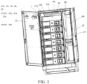
Figure 3 is a top view provided by the embodiment of the present application; -
Figure 4 is a side view provided by the embodiment of the present application; -
Figure 5 is an enlarged view of section A inFigure 4 ; -
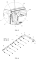
Figure 6 is a schematic diagram of the cooling pipeline provided by the embodiment of the present application; -
Figure 7 is a bottom view provided by the embodiment of the present application. - 1: Battery pack; 11: Cooling plate; 12: Cover; 13: Compartment; 2: Energy storage cabinet; 21: Cabinet body; 211: Partition; 212: Top plate; 2121: Top plate; 213: Bottom plate; 2131: Slot; 2132: Fixing hole; 2133: Drainage hole; 214: Side plate; 215: Cable installation plate; 22: First cabinet door; 23: Second cabinet door; 24: Containment compartment; 241: Battery compartment; 242: Electrical compartment; 25: Sandwich layer; 3: Firefighting equipment; 31: First aerosol firefighting device; 311: First smoke detector; 312: First aerosol fire extinguisher; 32: Second aerosol firefighting device; 33: Explosion-proof plate; 34: Water firefighting device; 341: First water firefighting pipeline; 4: Cooling pipeline; 41: First pipeline assembly; 411: First pipeline; 412: Three-way valve; 413: First connecting pipe; 42: Second pipeline assembly; 421: Second pipeline; 422: Wall-penetrating connector; 423: Second connecting pipe; 43: Drain valve; 5: Cooling device; 6: High-voltage box.
- Referring to
Figure 1 , the embodiment of this application provides an energy storage system. - The energy storage system includes a plurality of
battery packs 1, an energy storage cabinet 2, and firefighting equipment 3. - Referring to
Figure 2 , eachbattery pack 1 includes a plurality of battery groups, acooling plate 11, and acover 12. Thebattery packs 1 each can be a square battery pack, and have a waterproof level of IP67. thecover 12 includes a support and an upper cover disposed on the support, thecooling plate 11 is installed on the support, and thecover 12 and thecooling plate 11 form acompartment 13 for installing the plurality of battery groups. Thecooling plate 11 is in contact with the plurality of battery groups to dissipate heat. - Referring to
Figure 3 , the energy storage cabinet 2 includes acabinet body 21, afirst cabinet door 22, and asecond cabinet door 23. Thecabinet body 21 includes apartition 211, atop plate 212 and abottom plate 213 disposed oppositely, a back plate, and two oppositely disposedside plates 214. The twoside plates 214 are connected between thetop plate 212 and thebottom plate 213, and the twoside plates 214, thetop plate 212, the back plate, and thebottom plate 213 form acontainment compartment 24. Thepartition 211 is connected between thetop plate 212 and thebottom plate 213 and divides thecontainment compartment 24 into abattery compartment 241 and anelectrical compartment 242. The plurality ofbattery packs 1 are installed in thebattery compartment 241 and arranged vertically. Thefirst cabinet door 22 and thesecond cabinet door 23 are respectively hinged to the twoside plates 214, thefirst cabinet door 22 is used to cover thebattery compartment 241, and thesecond cabinet door 23 is used to cover theelectrical compartment 242. - The surfaces of the
cabinet body 21, thefirst cabinet door 22, and thesecond cabinet door 23 are coated from the inside out with an anti-corrosion layer and a wear-resistant layer. The anti-corrosion layer is made by applying epoxy primer to achieve an anti-corrosion grade of C5H, and the wear-resistant layer is made by applying polyurethane flour. Before coating the anti-corrosion layer, the surfaces of thecabinet body 21, thefirst cabinet door 22, and thesecond cabinet door 23 are treated by electrophoresis. Thetop plate 212, theside plates 214, and thebottom plate 213 all have rock wool inside, which has fireproof and insulation effects. - In this embodiment, the dimensions of the
cabinet body 21 are 1300×1300×2300mm in length, width, and height, respectively, making the footprint of the load-bearing base 1.69m2, greatly improving the energy density per unit area of the energy storage system. - Referring to
Figure 1 andFigure 3 , the firefighting equipment 3 includes a firstaerosol firefighting device 31, secondaerosol firefighting devices 32, an explosion-proof plate 33, and awater firefighting device 34. - The first
aerosol firefighting device 31 includes afirst smoke detector 311 and two firstaerosol fire extinguishers 312. Thefirst smoke detector 311 and the two firstaerosol fire extinguishers 312 are all installed on thefirst cabinet door 22, and they all correspond to thetopmost battery pack 1 among the plurality ofbattery packs 1. When thefirst smoke detector 311 detects a fire in thebattery compartment 241, it controls the firstaerosol fire extinguisher 312 to spray aerosol. Since the sprayed aerosol has a sinking trend and corresponds to thetopmost battery pack 1, it can fill theentire battery compartment 241 in a short time, improving the timeliness and effectiveness of fire extinguishing. - Referring to
Figure 2 , each secondaerosol firefighting device 32 is located in thecompartment 13 and is installed on the support of acorresponding battery pack 1. Each secondaerosol firefighting device 32 includes a second smoke detector and a second aerosol fire extinguisher. When the second smoke detector detects a fire in somebattery pack 1, it controls the second aerosol fire extinguisher to extinguish the fire inside thebattery pack 1. This is the first safety design. The firstaerosol firefighting device 31 is the second safety design. - Referring to
Figure 3 , thetop plate 212 has aninstallation hole 2121 located above thetopmost battery pack 1, and the explosion-proof plate 33 is screwed onto theinstallation hole 2121. When one or more battery packs 1 experience thermal runaway and generate a large amount of gas to an extent causing the explosion-proof plate 33 to burst, the explosion-proof plate 33 bursts instantaneously to release the internal pressure of thebattery compartment 241, preventing, as much as possible, thecontainment compartment 24 from exploding under excessive pressure, and no resulted fragment hurts people. - The
water firefighting device 34 includes a fire extinguishing water tank and a firstwater firefighting pipeline 341. The fire extinguishing water tank is installed in theelectrical compartment 242 and stores deionized water. The firstwater firefighting pipeline 341 is connected to and in communication with the fire extinguishing water tank and extends through thepartition 211 into thebattery compartment 241. The part of the firstwater firefighting pipeline 341 in the battery compartment is located above thetopmost battery pack 1. At the same time when the explosion-proof plate 33 bursts instantaneously to release the internal pressure of thebattery compartment 241, the first water firefighting pipeline irrigates a large amount of deionized water to immerse thebattery pack 1 and the interior of thebattery pack 1, causing the stop of the battery group thermal runaway and cool-down, preventing thebattery pack 1 from re-igniting. This is the third safety design. - Referring to
Figures 4 ,5, and 6 , the energy storage system also includes a cooling pipeline 4 and acooling device 5 installed in theelectrical compartment 242. The cooling pipeline 4 includes an inlet pipeline and an outlet pipeline. Both the inlet and outlet pipelines include interconnected first andsecond pipeline assemblies 41 and 42. The first pipeline assembly 41 includes a plurality offirst pipelines 411, a plurality of three-way valves 412, and a plurality of first connectingpipes 413. Thesecond pipeline assembly 42 includes asecond pipeline 421, a wall-penetratingconnector 422, and a second connectingpipe 423. - In the outlet pipeline, the
second pipeline 421 connects to the outlet of thecooling device 5, thepartition 211 has an installation hole, the wall-penetratingconnector 422 is installed in the installation hole, and the sealing performance of the wall-penetratingconnector 422 complies with IP66. The second connectingpipe 423 connects to one of thefirst pipelines 411. Each three-way valve 412 connects between adjacentfirst pipelines 411 and the first connectingpipes 413, and each first connectingpipe 413 connects to the inlet of the coolingplate 11 of a corresponding one of the battery packs 1. The plurality of three-way valves 412 include a plurality of first three-way valves 412 and a plurality of second three-way valves 412, the inner diameter of each first three-way valve 412 is smaller than the inner diameter of each second three-way valve 412, the plurality of first three-way valves 412 are located above the plurality of second three-way valves 412. In this embodiment, there are eight three-way valves 412 in each outlet pipeline, from top to bottom. The inner diameter of the first three of the three-way valves 412 is 8mm, and that of the remaining five is 12mm. This design aims to balance the cooling fluid flows through the coolingplates 11 of the battery packs 1 as much as possible. - A
drain valve 43 is installed on thefirst pipelines 411, and a self-sealing joint is provided at the end of each first connectingpipe 413 connected to the inlet of thecorresponding cooling plate 11, facilitating later maintenance by personnel. - In the inlet pipeline, the
second pipeline 421 is connected to the inlet of thecooling device 5, thepartition 211 has an installation hole, the wall-penetratingconnector 422 is installed in the installation hole, and the sealing performance of the wall-penetratingconnector 422 complies with IP66. The second connectingpipe 423 connects to one of thefirst pipelines 411. Each three-way valve 412 connects between adjacentfirst pipelines 411 and an adjacent one of the first connectingpipes 413, and each first connectingpipe 413 connects to the outlet of the coolingplate 11 of thecorresponding battery pack 1. - In this embodiment, there are eight three-
way valves 412 in each of the inlet and outlet pipelines, from top to bottom. In the inlet pipelines, the inner diameter of the first three three-way valves 412 is 8mm, and that of the remaining five is 12mm. This design aims to balance the cooling fluid flows through the coolingplates 11 of the battery packs 1 as much as possible. - In the inlet pipelines, an air drain valve 44 is installed on the
first pipeline 411, and a self-sealing joint is provided at the end of each first connectingpipe 413 connected to the inlet of thecorresponding cooling plate 11, facilitating later maintenance by personnel. - The
side plate 214 near thebattery compartment 241 is provided with asandwich layer 25, and part of thefirst pipelines 411, the three-way valves 412, and part of thesecond pipeline 421 are located within thesandwich layer 25. This design saves space and improves the utilization rate of space. - The
cooling device 5 includes a cooling liquid tank for storing cooling liquid and a pump station. The cooling liquid tank is connected to and in communication with thesecond pipeline 421, and the pump station is used to pump the cooling liquid into thesecond pipeline 421 of the outlet pipeline. - The
electrical compartment 242 is equipped with a high-voltage box 6 connected to the plurality of battery packs 1. In the cases where the high-voltage box 6 is equipped with a thermostat and a high-voltage circuit breaker, the thermostat controls the battery packs 1 to disconnect when it detects that the internal temperature of thecabinet 21 exceeds the set temperature; And when the high-voltage circuit breaker detects that the voltage exceeds the set voltage, it controls thebattery pack 1 to stop power supply. - In this embodiment, the electrical components of the high-voltage box 6 and the battery packs 11 are suitable for use in areas below 4000m in altitude.
- Referring to
Figures 4 and7 , thebottom plate 213 has fixingholes 2132, adrainage hole 2133, and a plurality ofslots 2131 arranged horizontally. The wall of each fixinghole 2132 is threaded, and the fixingholes 2132 are used to fix thebottom plate 213 to the foundation to improve the installation stability of the energy storage cabinet 2. Thedrainage hole 2133 is equipped with a check valve, which only allows the liquid inside the energy storage cabinet 2 to flow out. Theslots 2131 are for receiving the forks of a forklift, facilitating flexible movement of the energy storage cabinet 2. Thebottom plate 213 also has acable installation plate 215 surrounding theelectrical compartment 242, and thecable installation plate 215 has awiring hole 2151. Thewiring hole 2151 is for external wires to extend into theelectrical compartment 242 and connect with the high-voltage box 6.
Claims (15)
- An energy storage system comprising:a plurality of battery packs (1) arranged in a direction;an energy storage cabinet (2) comprising a cabinet body (21), characterized in that the cabinet body (21) comprises a containment compartment (24), the containment compartment (24) comprises a battery compartment (241) installed with the plurality of the battery packs (1);a firefighting equipment (3) comprising a first aerosol firefighting device (31), second aerosol firefighting devices (32), an explosion-proof plate (33), and a water firefighting device (34);characterized in that the first aerosol firefighting device (31) is installed in the energy storage cabinet (2); each second aerosol firefighting device (32) is installed on a corresponding one of the battery packs (1); the explosion-proof plate (33) is disposed as at least part of the battery compartment (241); the water firefighting device (34) is installed in the energy storage cabinet (2) and is configured to spray water into the battery compartment (241).
- The energy storage system according to claim 1, characterized in that the energy storage cabinet (2) further comprises a first cabinet door (22), the first cabinet door (22) is installed on one side of the cabinet body (21) and is disposed to cover the battery compartment (241), the first aerosol firefighting device (31) is installed on a side of the first cabinet door (22) facing the battery compartment (241).
- The energy storage system according to claim 2, characterized in that the first aerosol firefighting device (31) corresponds to the topmost battery pack (1) among the plurality of battery packs (1).
- The energy storage system according to claim 1, characterized in that the water firefighting device (34) comprises a first water firefighting pipeline (341), and the first water firefighting pipeline (341) is located above a topmost battery pack (1) among the plurality of battery packs (1).
- The energy storage system according to claim 1, characterized in that each battery pack (1) comprises a battery group, a cooling plate (11), and a cover (12); the cover (12) and the cooling plate (11) form a compartment (13) for installation of the battery group, and the second aerosol firefighting device (32) corresponding to the battery pack (1) is installed on the cover (12) and is located within the compartment (13).
- The energy storage system according to claim 1, characterized in that the cabinet body (21) comprises a bottom plate (213) opposite to the explosion-proof plate (33) and two oppositely disposed side plates (214), the two side plates (214) are connected between the explosion-proof plate (33) and the bottom plate (213), and the two side plates (214), the explosion-proof plate (33), and the bottom plate (213) form the containment compartment (24).
- The energy storage system according to claim 6, characterized in that the cabinet body (21) comprises a top plate (212) opposite to the bottom plate (213), and the explosion-proof plate (33) is installed on the top plate (212).
- The energy storage system according to claim 5, further comprising a cooling pipeline (4) and a cooling device (5); the cooling pipeline (4) comprises an inlet pipeline and an outlet pipeline, the inlet pipeline is connected between an inlet of the cooling device (5) and outlets of the cooling plates (11) of the plurality of the battery packs (1), and the outlet pipeline is connected between an outlet of the cooling device (5) and inlets of the cooling plates (11) of the plurality of the battery packs (1).
- The energy storage system according to claim 8, characterized in that at least part of the inlet pipeline and part of the outlet pipeline are located within a wall of the containment compartment (24).
- The energy storage system according to claim 9, characterized in that the inlet pipeline or the outlet pipeline comprises interconnected first pipeline assembly (41) and second pipeline assembly (42), the first pipeline assembly (41) is connected to the cooling plates (11) of the plurality of the battery packs (1), the second pipeline assembly (42) is connected to the cooling device (5), the cabinet body (21) comprises two oppositely disposed side plates (214), and at least part of the first pipeline assembly (41) is located within one of the side plates (214).
- The energy storage system according to claim 10, characterized in that the first pipeline assembly (41) comprises a plurality of first pipelines (411), a plurality of three-way valves (412), and a plurality of first connecting pipes (413), the plurality of the first pipelines (411) are connected between the outlets or the inlets of the cooling plates (11) and the second pipeline assembly (42), each three-way valve (412) is connected between two adjacent ones of the first pipelines (411) and a corresponding one of the first connecting pipes (413), each of the first connecting pipes (413) is further connected to the outlet or inlet of the cooling plate (11) of a corresponding one of the battery packs (1); the plurality of the three-way valves (412) comprise a plurality of first three-way valves (412) and a plurality of second three-way valves (412), an inner diameter of the first three-way valves (412) is smaller than an inner diameter of the second three-way valves (412), and the plurality of the first three-way valves (412) are located above the plurality of the second three-way valves (412).
- The energy storage system according to claim 10, characterized in that the containment compartment (24) further comprises an electrical compartment (242), the cooling device (5) is installed inside the electrical compartment (242); the cabinet body (21) further comprises a partition (211) between the two side plates (214), the partition (211) separates the electrical compartment (242) and the battery compartment (241), and has an installation hole; the second pipeline assembly (42) comprises a second pipeline (421), a wall-penetrating connector (422), and a second connecting pipe (423) connected in sequence, the second pipeline (421) is further connected to the first pipeline assembly (41) and is located inside the battery compartment (241), the wall-penetrating connector (422) is installed in the installation hole, and the second connecting pipe (423) is further connected to the cooling device (5).
- The energy storage system according to claim 6, characterized in that the bottom plate (213) has fixing holes (2132), a drainage hole (2133), and slots (2131), the fixing holes (2132) are configured to fix the bottom plate (213) to a foundation, the drainage hole (2133) is connected to and in communication with the battery compartment (241), and
the drainage hole (2133) has a check valve, the check valve allows liquid inside the energy storage cabinet (2) to flow out, and the slots (2131) are configured for receiving forks of a forklift. - The energy storage system according to claim 6, characterized in that the containment compartment (24) further comprises an electrical compartment (242), the cabinet body (21) also comprises a partition (211) between the two side plates (214), the partition (211) separates the electrical compartment (242) and the battery compartment (241), the bottom plate (213) comprises a cable installation plate (215) surrounding the electrical compartment (242), the cable installation plate (215) has a wiring hole (2151), the electrical compartment (242) has a high-voltage box (6) inside connected to the plurality of battery packs (1), and the wiring hole (2151) is configured for a connection between external wires with the high-voltage box (6).
- The energy storage system according to any one of claims 1-14, characterized in that the first aerosol firefighting device (31) or each second aerosol firefighting device (32) comprises a smoke detector (311) and at least one aerosol fire extinguisher (312), and the smoke detector (311) is configured to monitor fires and control the at least one aerosol fire extinguisher (312) to activate fire extinguishing.
Applications Claiming Priority (2)
| Application Number | Priority Date | Filing Date | Title |
|---|---|---|---|
| CN202321721289.7U CN220138399U (en) | 2023-06-30 | 2023-06-30 | Energy storage system |
| PCT/CN2024/102563 WO2025002406A1 (en) | 2023-06-30 | 2024-06-28 | Energy storage system |
Publications (1)
| Publication Number | Publication Date |
|---|---|
| EP4510296A1 true EP4510296A1 (en) | 2025-02-19 |
Family
ID=88963718
Family Applications (1)
| Application Number | Title | Priority Date | Filing Date |
|---|---|---|---|
| EP24787399.5A Pending EP4510296A1 (en) | 2023-06-30 | 2024-06-28 | Energy storage system |
Country Status (5)
| Country | Link |
|---|---|
| US (1) | US20250096409A1 (en) |
| EP (1) | EP4510296A1 (en) |
| CN (1) | CN220138399U (en) |
| AU (1) | AU2024287281A1 (en) |
| WO (1) | WO2025002406A1 (en) |
Families Citing this family (2)
| Publication number | Priority date | Publication date | Assignee | Title |
|---|---|---|---|---|
| CN220138399U (en) * | 2023-06-30 | 2023-12-05 | 武汉亿纬储能有限公司 | Energy storage system |
| CN121601874A (en) * | 2026-01-22 | 2026-03-03 | 宁德时代新能源科技股份有限公司 | Energy storage device, assembly method thereof, energy storage system and charging network |
Family Cites Families (7)
| Publication number | Priority date | Publication date | Assignee | Title |
|---|---|---|---|---|
| CN108615838B (en) * | 2018-05-04 | 2021-01-22 | 安徽上造智能设备科技有限公司 | High-strength explosion-proof shockproof battery for new energy automobile |
| CN112768819A (en) * | 2021-01-20 | 2021-05-07 | 宁波中科孚奇能源科技有限公司 | Energy storage battery pack with high fire safety and energy storage battery container |
| CN115154958A (en) * | 2022-04-21 | 2022-10-11 | 山东德晋新能源科技有限公司 | Energy storage container with multiple fire-fighting systems and fire-fighting method thereof |
| CN218498227U (en) * | 2022-06-22 | 2023-02-17 | 上海瑞浦青创新能源有限公司 | Battery cluster and battery cabinet |
| CN218498197U (en) * | 2022-06-30 | 2023-02-17 | 上海瑞浦青创新能源有限公司 | Liquid cooling pipeline of electrochemical energy storage system |
| CN116345002B (en) * | 2023-04-17 | 2026-03-20 | 北京晟运能源科技有限公司 | A containerized liquid-cooled energy storage integrated system based on multi-level fire protection deployment |
| CN220138399U (en) * | 2023-06-30 | 2023-12-05 | 武汉亿纬储能有限公司 | Energy storage system |
-
2023
- 2023-06-30 CN CN202321721289.7U patent/CN220138399U/en active Active
-
2024
- 2024-06-28 WO PCT/CN2024/102563 patent/WO2025002406A1/en not_active Ceased
- 2024-06-28 EP EP24787399.5A patent/EP4510296A1/en active Pending
- 2024-06-28 AU AU2024287281A patent/AU2024287281A1/en active Pending
- 2024-11-29 US US18/964,288 patent/US20250096409A1/en active Pending
Also Published As
| Publication number | Publication date |
|---|---|
| AU2024287281A1 (en) | 2025-04-03 |
| CN220138399U (en) | 2023-12-05 |
| WO2025002406A1 (en) | 2025-01-02 |
| US20250096409A1 (en) | 2025-03-20 |
Similar Documents
| Publication | Publication Date | Title |
|---|---|---|
| EP4510296A1 (en) | Energy storage system | |
| CN216603874U (en) | Two-stage fire extinguishing system with energy storage battery clusters | |
| US12186610B2 (en) | Operation control method suitable for fire extinguishing system of extra-high voltage converter station | |
| CN217409598U (en) | Multistage energy storage fire extinguishing system | |
| CN216653185U (en) | Fire extinguishing system and energy storage system | |
| CN115837134A (en) | Method and system for preventing and controlling nitrogen inhibition and high-pressure atomization fire extinguishing agent of energy storage power station | |
| CN119877899A (en) | Precast concrete energy storage cabin | |
| CN216725586U (en) | Battery fire hose suitable for new forms of energy echelon power battery energy storage system | |
| CN219423616U (en) | Mixed gas fire extinguishing device for distributed deep energy storage container | |
| CN108619635B (en) | Compressed air foam intelligent fire protection device for external floating roof crude oil storage tanks | |
| CN215679576U (en) | Energy storage system | |
| CN212625854U (en) | Battery energy storage system | |
| EP4593180A1 (en) | Energy storage system and electric apparatus | |
| CN219815082U (en) | Liquid CO 2-based fire extinguishing and cooling system for electrochemical energy storage prefabricated cabin | |
| CN219167591U (en) | Special nozzle for energy storage and fire control and energy storage battery pack | |
| CN224056522U (en) | Liquid nitrogen fire extinguishing device | |
| CN216710376U (en) | Dangerous chemical storage device | |
| CN115882156A (en) | A prefabricated energy storage device | |
| CN222072094U (en) | Sinking energy storage system and sinking energy storage power station | |
| CN117559053B (en) | Foundation pit type energy storage system | |
| CN223787971U (en) | Battery devices and electrical equipment | |
| CN223263335U (en) | Fire control foam liquid feeding device | |
| CN219983754U (en) | Fire-fighting system for battery prefabricated cabin | |
| CN206252753U (en) | A kind of fire-fighting system of gas turbine | |
| CN215804821U (en) | Power generation container for oil field drilling machine |
Legal Events
| Date | Code | Title | Description |
|---|---|---|---|
| STAA | Information on the status of an ep patent application or granted ep patent |
Free format text: STATUS: UNKNOWN |
|
| STAA | Information on the status of an ep patent application or granted ep patent |
Free format text: STATUS: THE INTERNATIONAL PUBLICATION HAS BEEN MADE |
|
| PUAI | Public reference made under article 153(3) epc to a published international application that has entered the european phase |
Free format text: ORIGINAL CODE: 0009012 |
|
| STAA | Information on the status of an ep patent application or granted ep patent |
Free format text: STATUS: REQUEST FOR EXAMINATION WAS MADE |
|
| 17P | Request for examination filed |
Effective date: 20241018 |
|
| AK | Designated contracting states |
Kind code of ref document: A1 Designated state(s): AL AT BE BG CH CY CZ DE DK EE ES FI FR GB GR HR HU IE IS IT LI LT LU LV MC ME MK MT NL NO PL PT RO RS SE SI SK SM TR |
|
| RAP3 | Party data changed (applicant data changed or rights of an application transferred) |
Owner name: EVE ENERGY STORAGE CO., LTD |