EP4510163A1 - Switchig assembly for domestic use - Google Patents
Switchig assembly for domestic use Download PDFInfo
- Publication number
- EP4510163A1 EP4510163A1 EP23191992.9A EP23191992A EP4510163A1 EP 4510163 A1 EP4510163 A1 EP 4510163A1 EP 23191992 A EP23191992 A EP 23191992A EP 4510163 A1 EP4510163 A1 EP 4510163A1
- Authority
- EP
- European Patent Office
- Prior art keywords
- switching assembly
- cover element
- functional element
- cover
- functional
- Prior art date
- Legal status (The legal status is an assumption and is not a legal conclusion. Google has not performed a legal analysis and makes no representation as to the accuracy of the status listed.)
- Pending
Links
Images




Classifications
-
- H—ELECTRICITY
- H01—ELECTRIC ELEMENTS
- H01H—ELECTRIC SWITCHES; RELAYS; SELECTORS; EMERGENCY PROTECTIVE DEVICES
- H01H23/00—Tumbler or rocker switches, i.e. switches characterised by being operated by rocking an operating member in the form of a rocker button
- H01H23/02—Details
- H01H23/12—Movable parts; Contacts mounted thereon
- H01H23/14—Tumblers
- H01H23/143—Tumblers having a generally flat elongated shape
-
- H—ELECTRICITY
- H01—ELECTRIC ELEMENTS
- H01H—ELECTRIC SWITCHES; RELAYS; SELECTORS; EMERGENCY PROTECTIVE DEVICES
- H01H23/00—Tumbler or rocker switches, i.e. switches characterised by being operated by rocking an operating member in the form of a rocker button
- H01H23/02—Details
- H01H23/04—Cases; Covers
- H01H23/06—Dustproof, splashproof, drip-proof, waterproof, or flameproof casings
-
- H—ELECTRICITY
- H01—ELECTRIC ELEMENTS
- H01H—ELECTRIC SWITCHES; RELAYS; SELECTORS; EMERGENCY PROTECTIVE DEVICES
- H01H9/00—Details of switching devices, not covered by groups H01H1/00 - H01H7/00
- H01H9/02—Bases, casings, or covers
- H01H9/04—Dustproof, splashproof, drip-proof, waterproof, or flameproof casings
-
- H—ELECTRICITY
- H01—ELECTRIC ELEMENTS
- H01H—ELECTRIC SWITCHES; RELAYS; SELECTORS; EMERGENCY PROTECTIVE DEVICES
- H01H2221/00—Actuators
- H01H2221/066—Actuators replaceable
Definitions
- the disclosure generally relates to a switching assembly which is configured for domestic use.
- Electrical equipment such as switches
- the degree of protection is assessed and defined according to their exposure.
- DIN EN 60529 defines the protection requirements of electrical equipment within households. It requires, among other things, for a water spray test with following high-voltage test to remove all parts of a switching assembly that can be detached without tools.
- Switching assemblies according to the conventional technology comply with the protection class. These switching assemblies usually include a design frame which accommodates a cover element or housing top in a way that it cannot be removed without tools.
- Fig. 1 illustrates a switching assembly 100 for households according to the conventional technology.
- the switching assembly has a cover element 10 and design frame 12.
- the dimension of the cover element 10 matches the dimension of the design frame 12 in a piece-and-counter-piece manner.
- the design frame 12 surrounds the cover element 10 in a way which impedes the finger of a user to grasp the cover element 10.
- the switching assembly 100 prevents a user to remove the cover element 10 without the aid of tools.
- the switching assembly 100 undergoes the water spray test with the following high-voltage test assembled as shown.
- a switching assembly configured for domestic use.
- the switching assembly comprises a design frame and a switch insert which has a baseplate.
- the switching assembly further comprises a functional element which is configured to attach the design frame to the switch insert.
- the switching assembly also comprises a cover element which is configured to be attached to the functional element and to be actuated by a user.
- the functional element- is configured to prevent interfering objects from entering the switching assembly, to prevent that water inserts the switching assembly and to actuate the switch insert upon a user actuating the cover element.
- the switching assembly may be configured to be used for flush-mounted or for surface-mounted installations.
- Interfering objects may refer to particles or items of environmental or man-made origin. Examples of interfering objects may include water, dust, splash water, condensed water, body parts of persons or animals, textile parts, metal parts, wooden parts, paper parts, or the like.
- Switching assembly may refer to an interface between a domestic electrical network with a load and the cover element. At the network side, the switching assembly may be connected to the conductors of the electrical network via an electrical switch.
- the electrical switch may comprise electrical contacts to close a respective circuitry of the electrical network.
- To actuate the switching assembly may refer to actuate the electrical switch.
- Cover element may refer to the outer part of the switching assembly and the interface for the user.
- the cover element may be adapted to hygienic and/or design requirements in terms of material, size and/or look.
- the material of the cover element may be germophobic and/or easily cleanable. It may be surface- tempered such that it is anti-fingerprint and/or reduces ethaltic stains.
- the cover element may be adapted to the environment of the switching assembly. It may, for instance, be UV-resistant or water-resistant.
- Functional element refers to a middle piece between the cover element and the switch insert.
- the cover element may be movably mounted to the functional element while the functional element is permanently attached to the switch insert.
- the functional element may translate an input to from the cover element to the switch insert. For instance, a mechanical input to the cover element may be translated by the functional element to the electrical switch insert which may be opened or closed electrically, respectively.
- the functional element may have clamping and/or snap-in devices on its bottom side, i.e. its side facing the baseplate element.
- the clamping and/or snap-in devices may be configured to clamp or, respectively, snap-in to an inner rocker of the design frame. Tools, for instance a screw driver, may be necessary to remove the functional element.
- the cover element and the functional element may be formed of the same material.
- the cover element and the functional element may be formed of different materials.
- the functional element may be formed of plastic, thermoplastic or resin.
- the cover element may be formed of disposable material, or biologically degradable material.
- the cover element may be formed of plastic, thermoplastic, duroplastic, resin, porcelain, pressed fiber boards, plastic, resin, glass, wood, bamboo, cardboard, copper, stainless steal, or any combination thereof.
- the cover element of the switch assembly may comprise an outer layer of textile, plastic, paper, wallpaper, or coated paper.
- the cover element may be varnished.
- the surface of the cover element may be matt or glossy.
- the baseplate of the design frame may be formed of the same material as the cover material.
- the cover element may be configured to close or interrupt an electrical line.
- the functional element comprises a silicon sealing which is configured to seal the baseplate element.
- the functional element may be a rocker element.
- the functional elements may be any of a pushbutton element, a wipe element, a slider element, a rotate element, a gesture element, a key element, a dimmer element, or a light sensor element.
- the cover element may include a device, in particular any of a sensor such as a motion sensor, a luminosity sensor, a temperature sensor or a humidity sensor. It may comprise a light insert for as ambient illumination.
- the light insert may include at least one light-emitting diode, LED.
- the cover element and the functional element may form a two-part sub-system for switching assemblies that is adaptable to respective use cases and requirements.
- the cover element and the functional element are mutually adjusted.
- the functional element may be dimensioned to be accommodated by the design frame or housing cover when assembled.
- the design frame or housing cover may surround the functional element leaving no room for the introduction of fingers. Tools may be necessary to remove or to install the functional element.
- the functional element may comprise at least one recess.
- the functional element may comprise at least one opening.
- the recess or opening may be configured for installation purposes.
- the cover element may be configured to close the at least one opening of the functional element when the functional element is attached onto the design frame, thereby sealing the combination of the design frame and functional element.
- the cover element may be removably attached to the functional element.
- the cover element may comprise clips, the clips being configured to engage with the functional element to attach the cover element to the functional element.
- the functional element may comprise recesses or opening into which the clips of the cover element may engage.
- the functional element may be configured to be permanently attached to the design frame.
- the functional element may be attached to the design frame by screws.
- the size of the cover element extends beyond the size of the functional element.
- the cover element may comprise a circumferential flange.
- the circumferential flange may be a flat protrusion of the cover element in a direction parallel to the cover element.
- the circumferential flange may extend in a dimension perpendicular to the cover element.
- the thickness of the circumferential flange may be homogenous, or heterogenous. In the latter case, it may include bumps.
- the cover element may be configured to be graspable for a user and to be removeable upon a user grasping the cover element. For instance, the user may position his/her fingertips on the side of the circumferential flange which is turned away from him/her. The user may grasp the circumferential flange and pull the cover element towards him/her.
- the shape of the cover element may be square, rectangular, round, oval, or radially. It may be symmetrical or asymmetrical.
- the dimension of the cover element may be any of 80 mm * 80 mm, 63 mm * 63 mm, 50 mm * 50 mm.
- the flange of the cover element may have a height in a range of 2 - 20 mm, in particular of any of 5 mm, 7 mm, or 9 mm, in a direction perpendicular to the switching assembly
- the functional element may be dimensioned in any of 60 mm * 60 mm, 50 mm * 50 mm, 40 mm * 40 mm, 30 mm * 30 mm.
- the outer edges of the baseplate element may have any dimensions, for example 80 mm * 80 mm, 63 mm * 63 mm or 50 mm * 50 mm.
- the baseplate element may have a height in a range of 10 - 20 mm, in particular of any of 11 mm, 14 mm, 18 mm, in a direction perpendicular to the switching assembly.
- the flange of the cover element When assembled, the flange of the cover element may be spaced apart from the baseplate element in a direction perpendicular to the switching assembly.
- the space between the baseplate element and the cover element may allow for movement of the cover element and/or positioning of fingers.
- the space between the baseplate element and the cover element may be in a range of 3 - 13 mm, in particular any of 5 mm, 7 mm, 9 mm, 11 mm.
- the switching assembly may comprise a flush-mounted element.
- the baseplate element of the switching assembly may be configured to be permanently attached to the flush-mounted element.
- the switching assembly may be configured to comply with the protection grade DIN EN 60529. This means that even though the cover element has to be removed, the remaining switching assembly still passes a high-voltage test. In embodiments, the switching assembly meets the regulations for touch protection.
- Fig. 1b presents a schematic diagram of a switching assembly 100 according to prior art in disassembled form.
- the switching assembly 100 may be a rocker switching assembly.
- the switching assembly 100 may have a cover element 10 and a design frame 12.
- the dimension of the cover element 10 may match the dimension of the design frame 12 in a piece-and-counter-piece manner.
- the design frame 12 may surround the cover element 10 in a way which may impede the fingers of a user to grasp the cover element 10. Thereby, the switching assembly 100 may prevent a user to remove the cover element 10 without the aid of tools.
- a switching interface 18 of the switch insert may be designed in that way that a rocker with design features can be fixed on.
- the switching interface 18 may be mounted tiltable to the switching insert. When the cover element 100 is actuated by a user, the switching interface 18 may close or open the electrical circuit of the domestic network and a load.
- Fig. 1c which also illustrates a schematic diagram of a switching assembly 100 according to prior art in a side perspective.
- the cover element 10 may integrated to the design frame 12 thereby preventing fingers 19 of a user to grasp and remove the cover element 10 of the switching assembly 100.
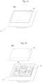
- Fig. 2 illustrates a schematic diagram of a switching assembly 200 in assembled form according to embodiments described herein.
- the switching assembly 200 may have a cover element 20, and a design frame 24 with a baseplate 22.
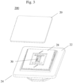
- FIG. 3 illustrates a schematic diagram of the switching 200 in partly disassembled form.
- the cover element 20 is removed allowing to view the functional element 28.
- the functional element 28 may be fixed to the switching interface 18 of the switch insert during the water spray test.
- the functional element 28 may have openings 27 for re-installation purposes.
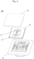
- Fig. 4 illustrates a schematic diagram of the switching assembly 200 in disassembled form.
- the cover element 20 may be snapped onto the functional element 28.
- the functional element 28 may be dimensioned to fit into a recess of the design frame 24 and to be permanently fixed to the insert via the switching interface 18.
- the functional element 28 may have openings 27. Openings 27 may be configured to allow a screwdriver to enter and/or to allow to solve a rear detent. Openings 27 may be configured to allow clamping and/or snap-in devices to be unlocked, for instance with a screw driver.
- Fig. 5 illustrates a schematic diagram of the switching assembly 200 from a side perspective.
- the cover element 20 may have a circumferential flange 29 allowing the fingers 26 of a user to be positioned on the backside of the cover element 20.
- the user may position his/her fingers between the circumferential flange 29 and the baseplate element 22.
- a user may apply a lever to the circumferential flange 29 and remove the cover element 20 from the switch insert.
- the circumferential flange 29 of the cover element may be spaced apart from the baseplate element 22 in a direction perpendicular to the switching assembly. The space may allow for movement of the cover element 20 and/or positioning of fingers.
- the switching assembly 200 may further comprise a soft sealing 23, for instance made of silicon.
- Fig. 6 illustrates a schematic diagram of a cover element 20 and a functional element 28 according to an embodiment.
- the functional element 28 may have protrusions 32 to permanently fix the functional element 28 to a switching assembly and to translate an actuation of the switching assembly into an input to an electric switch.
- the protrusions 32 may accommodate screws.
- the protrusions may comprise clamping and/or snap-in devices 32.
- the clamping and/or snap-in devices 32 may be configured to clamp or, respectively, snap-in to an inner rocker (not shown) of the design frame.
- the functional element 28 may have a recess or slot 30 or hole for installation of a status indicator or illumination device.
- the cover element 20 may have clips 34 to clip the cover element 20 to the functional element 28. Tools, for instance a screw driver, may be necessary to remove the functional element.
- Fig. 7 illustrates a schematic diagram of a cover element 20 mounted to a functional element 28 according to an embodiment.
- the cover element 20 may have a circumferential flange 29 which may extend beyond the functional element 28 a dimension parallel to the cover element 20.
- the circumferential flange 29 may have a homogeneous thickness.
Landscapes
- Switch Cases, Indication, And Locking (AREA)
Abstract
A switching assembly for domestic use (200) is provided. The switching assembly comprises a design frame (24) and a switch insert (22). The switching assembly further comprises a functional element which is configured to attach the design frame to the switch insert. The switching assembly also comprises a cover element (20) which is configured to be to be attached to the functional element and to be actuated by a user. The functional element is configured to prevent interfering objects from entering the switching assembly and to actuate the switch insert upon a user actuating the cover element.
Description
- The disclosure generally relates to a switching assembly which is configured for domestic use.
- Electrical equipment, such as switches, are required to provide a certain degree of protection against interfering objects. Thereby, health and life risks should be prevented. The degree of protection is assessed and defined according to their exposure. For instance, the protection class DIN EN 60529 defines the protection requirements of electrical equipment within households. It requires, among other things, for a water spray test with following high-voltage test to remove all parts of a switching assembly that can be detached without tools.
- Switching assemblies according to the conventional technology comply with the protection class. These switching assemblies usually include a design frame which accommodates a cover element or housing top in a way that it cannot be removed without tools.
-
Fig. 1 illustrates aswitching assembly 100 for households according to the conventional technology. The switching assembly has acover element 10 anddesign frame 12. The dimension of thecover element 10 matches the dimension of thedesign frame 12 in a piece-and-counter-piece manner. When assembled, thedesign frame 12 surrounds thecover element 10 in a way which impedes the finger of a user to grasp thecover element 10. Thereby, theswitching assembly 100 prevents a user to remove thecover element 10 without the aid of tools. Thus, theswitching assembly 100 undergoes the water spray test with the following high-voltage test assembled as shown. - There are, however, reasons to configure a switching assembly in a way which enables a user to grasp and remove the cover element. For instance, aesthetic and design purposes might lead to dimensions of the cover element that is easily to be grapped. Also, hygiene measures might require a cover element to be easily disposable without the aid of tools.
- According to an aspect, a switching assembly is provided. The switching assembly is configured for domestic use. The switching assembly comprises a design frame and a switch insert which has a baseplate. The switching assembly further comprises a functional element which is configured to attach the design frame to the switch insert. The switching assembly also comprises a cover element which is configured to be attached to the functional element and to be actuated by a user. The functional element-is configured to prevent interfering objects from entering the switching assembly, to prevent that water inserts the switching assembly and to actuate the switch insert upon a user actuating the cover element.
- The switching assembly may be configured to be used for flush-mounted or for surface-mounted installations.
- Interfering objects, as used herein, may refer to particles or items of environmental or man-made origin. Examples of interfering objects may include water, dust, splash water, condensed water, body parts of persons or animals, textile parts, metal parts, wooden parts, paper parts, or the like.
- Switching assembly, as used herein, may refer to an interface between a domestic electrical network with a load and the cover element. At the network side, the switching assembly may be connected to the conductors of the electrical network via an electrical switch. The electrical switch may comprise electrical contacts to close a respective circuitry of the electrical network. To actuate the switching assembly, as used herein, may refer to actuate the electrical switch.
- Cover element, as used herein, may refer to the outer part of the switching assembly and the interface for the user. The cover element may be adapted to hygienic and/or design requirements in terms of material, size and/or look. For instance, the material of the cover element may be germophobic and/or easily cleanable. It may be surface- tempered such that it is anti-fingerprint and/or reduces ethaltic stains. In instances, the cover element may be adapted to the environment of the switching assembly. It may, for instance, be UV-resistant or water-resistant.
- Functional element, as used herein, refers to a middle piece between the cover element and the switch insert. The cover element may be movably mounted to the functional element while the functional element is permanently attached to the switch insert. The functional element may translate an input to from the cover element to the switch insert. For instance, a mechanical input to the cover element may be translated by the functional element to the electrical switch insert which may be opened or closed electrically, respectively. Herein, the terms functional element and rocker and refer to the same element. The functional element may have clamping and/or snap-in devices on its bottom side, i.e. its side facing the baseplate element. The clamping and/or snap-in devices may be configured to clamp or, respectively, snap-in to an inner rocker of the design frame. Tools, for instance a screw driver, may be necessary to remove the functional element.
- The cover element and the functional element may be formed of the same material. The cover element and the functional element may be formed of different materials. The functional element may be formed of plastic, thermoplastic or resin. The cover element may be formed of disposable material, or biologically degradable material. The cover element may be formed of plastic, thermoplastic, duroplastic, resin, porcelain, pressed fiber boards, plastic, resin, glass, wood, bamboo, cardboard, copper, stainless steal, or any combination thereof.
- In embodiments, the cover element of the switch assembly may comprise an outer layer of textile, plastic, paper, wallpaper, or coated paper. The cover element may be varnished. The surface of the cover element may be matt or glossy.
- The baseplate of the design frame may be formed of the same material as the cover material.
- Further features are derivable from the dependent claims.
- In embodiments, the cover element may be configured to close or interrupt an electrical line.
- According to embodiments, the functional element comprises a silicon sealing which is configured to seal the baseplate element.
- The functional element may be a rocker element. The functional elements may be any of a pushbutton element, a wipe element, a slider element, a rotate element, a gesture element, a key element, a dimmer element, or a light sensor element.
- The cover element may include a device, in particular any of a sensor such as a motion sensor, a luminosity sensor, a temperature sensor or a humidity sensor. It may comprise a light insert for as ambient illumination. The light insert may include at least one light-emitting diode, LED.
- The cover element and the functional element may form a two-part sub-system for switching assemblies that is adaptable to respective use cases and requirements. The cover element and the functional element are mutually adjusted. The functional element may be dimensioned to be accommodated by the design frame or housing cover when assembled. The design frame or housing cover may surround the functional element leaving no room for the introduction of fingers. Tools may be necessary to remove or to install the functional element.
- The functional element may comprise at least one recess. The functional element may comprise at least one opening. The recess or opening may be configured for installation purposes.
- In embodiments, the cover element may be configured to close the at least one opening of the functional element when the functional element is attached onto the design frame, thereby sealing the combination of the design frame and functional element.
- In embodiments, the cover element may be removably attached to the functional element. The cover element may comprise clips, the clips being configured to engage with the functional element to attach the cover element to the functional element. The functional element may comprise recesses or opening into which the clips of the cover element may engage.
- In embodiments, the functional element may be configured to be permanently attached to the design frame. The functional element may be attached to the design frame by screws.
- In embodiments, the size of the cover element extends beyond the size of the functional element. The cover element may comprise a circumferential flange. The circumferential flange may be a flat protrusion of the cover element in a direction parallel to the cover element. In embodiments, the circumferential flange may extend in a dimension perpendicular to the cover element. The thickness of the circumferential flange may be homogenous, or heterogenous. In the latter case, it may include bumps.
- The cover element may be configured to be graspable for a user and to be removeable upon a user grasping the cover element. For instance, the user may position his/her fingertips on the side of the circumferential flange which is turned away from him/her. The user may grasp the circumferential flange and pull the cover element towards him/her.
- The shape of the cover element may be square, rectangular, round, oval, or radially. It may be symmetrical or asymmetrical. The dimension of the cover element may be any of 80 mm * 80 mm, 63 mm * 63 mm, 50 mm * 50 mm.
- The flange of the cover element may have a height in a range of 2 - 20 mm, in particular of any of 5 mm, 7 mm, or 9 mm, in a direction perpendicular to the switching assembly The functional element may be dimensioned in any of 60 mm * 60 mm, 50 mm * 50 mm, 40 mm * 40 mm, 30 mm * 30 mm.
- The outer edges of the baseplate element may have any dimensions, for example 80 mm * 80 mm, 63 mm * 63 mm or 50 mm * 50 mm.
- The baseplate element may have a height in a range of 10 - 20 mm, in particular of any of 11 mm, 14 mm, 18 mm, in a direction perpendicular to the switching assembly.
- When assembled, the flange of the cover element may be spaced apart from the baseplate element in a direction perpendicular to the switching assembly. The space between the baseplate element and the cover element may allow for movement of the cover element and/or positioning of fingers. The space between the baseplate element and the cover element may be in a range of 3 - 13 mm, in particular any of 5 mm, 7 mm, 9 mm, 11 mm.
- In embodiments, the switching assembly may comprise a flush-mounted element. The baseplate element of the switching assembly may be configured to be permanently attached to the flush-mounted element.
- The switching assembly may be configured to comply with the protection grade DIN EN 60529. This means that even though the cover element has to be removed, the remaining switching assembly still passes a high-voltage test. In embodiments, the switching assembly meets the regulations for touch protection.
-
- Fig. 1a
- illustrates a schematic diagram of a switching assembly according to prior art in assembled form;
- Fig. 1b
- illustrates a schematic diagram of a switching assembly according to prior art in disassembled form;
- Fig. 1c
- illustrates a schematic diagram of a switching assembly according to prior art;
- Fig. 2
- illustrates a schematic diagram of a switching assembly in assembled form according to an embodiment;
- Fig. 3
- illustrates a schematic diagram of the switching assembly of
Fig. 2 in partly disassembled form; - Fig. 4
- illustrates a schematic diagram of the switching assembly of
Fig. 2 in disassembled form; - Fig. 5
- illustrates a schematic diagram of the switching assembly from a side perspective;
- Fig. 6
- illustrates a schematic diagram of a cover element and a functional element according to an embodiment;
- Fig. 7
- illustrates a schematic diagram of a cover element mounted to a functional element according to an embodiment.
- In the following, embodiments are set forth to describe specific examples presented herein. The person skilled in the art will recognize that one or more other examples and/ or variations of these examples may be practiced without all the specific details outlined below. Also, well known features may not be described in detail so as not to obscure the description of the examples herein. For the ease of illustration, like reference numerals are used in different figures to refer to the same elements or additional instances of the same element. Features illustrated or described as part of one embodiment can be used on or in conjugation with any other embodiment to yield yet a further embodiment.
- Referring now to the drawings,
Fig. 1b presents a schematic diagram of a switchingassembly 100 according to prior art in disassembled form. As exemplarily illustrated withFig. 1b , the switchingassembly 100 may be a rocker switching assembly. The switchingassembly 100 may have acover element 10 and adesign frame 12. The dimension of thecover element 10 may match the dimension of thedesign frame 12 in a piece-and-counter-piece manner. When assembled, as shown inFig. 1a , thedesign frame 12 may surround thecover element 10 in a way which may impede the fingers of a user to grasp thecover element 10. Thereby, the switchingassembly 100 may prevent a user to remove thecover element 10 without the aid of tools. - A switching
interface 18 of the switch insert may be designed in that way that a rocker with design features can be fixed on. The switchinginterface 18 may be mounted tiltable to the switching insert. When thecover element 100 is actuated by a user, the switchinginterface 18 may close or open the electrical circuit of the domestic network and a load. - Now referring to
Fig. 1c which also illustrates a schematic diagram of a switchingassembly 100 according to prior art in a side perspective. Thecover element 10 may integrated to thedesign frame 12 thereby preventingfingers 19 of a user to grasp and remove thecover element 10 of the switchingassembly 100. -
Fig. 2 illustrates a schematic diagram of a switchingassembly 200 in assembled form according to embodiments described herein. The switchingassembly 200 may have acover element 20, and adesign frame 24 with abaseplate 22. - Now referring to
Fig. 3 which illustrates a schematic diagram of the switching 200 in partly disassembled form. Here, thecover element 20 is removed allowing to view thefunctional element 28. Thefunctional element 28 may be fixed to the switchinginterface 18 of the switch insert during the water spray test. Thefunctional element 28 may haveopenings 27 for re-installation purposes. -
Fig. 4 illustrates a schematic diagram of the switchingassembly 200 in disassembled form. Thecover element 20 may be snapped onto thefunctional element 28. Thefunctional element 28 may be dimensioned to fit into a recess of thedesign frame 24 and to be permanently fixed to the insert via the switchinginterface 18. Thefunctional element 28 may haveopenings 27.Openings 27 may be configured to allow a screwdriver to enter and/or to allow to solve a rear detent.Openings 27 may be configured to allow clamping and/or snap-in devices to be unlocked, for instance with a screw driver. -
Fig. 5 illustrates a schematic diagram of the switchingassembly 200 from a side perspective. Thecover element 20 may have acircumferential flange 29 allowing thefingers 26 of a user to be positioned on the backside of thecover element 20. The user may position his/her fingers between thecircumferential flange 29 and thebaseplate element 22. A user may apply a lever to thecircumferential flange 29 and remove thecover element 20 from the switch insert. Thecircumferential flange 29 of the cover element may be spaced apart from thebaseplate element 22 in a direction perpendicular to the switching assembly. The space may allow for movement of thecover element 20 and/or positioning of fingers. The switchingassembly 200 may further comprise asoft sealing 23, for instance made of silicon. -
Fig. 6 illustrates a schematic diagram of acover element 20 and afunctional element 28 according to an embodiment. Thefunctional element 28 may haveprotrusions 32 to permanently fix thefunctional element 28 to a switching assembly and to translate an actuation of the switching assembly into an input to an electric switch. Theprotrusions 32 may accommodate screws. The protrusions may comprise clamping and/or snap-indevices 32. The clamping and/or snap-indevices 32 may be configured to clamp or, respectively, snap-in to an inner rocker (not shown) of the design frame. Thefunctional element 28 may have a recess orslot 30 or hole for installation of a status indicator or illumination device. Thecover element 20 may haveclips 34 to clip thecover element 20 to thefunctional element 28. Tools, for instance a screw driver, may be necessary to remove the functional element. -
Fig. 7 illustrates a schematic diagram of acover element 20 mounted to afunctional element 28 according to an embodiment. Thecover element 20 may have acircumferential flange 29 which may extend beyond the functional element 28 a dimension parallel to thecover element 20. Thecircumferential flange 29 may have a homogeneous thickness.
Claims (15)
- A switching assembly (200) for domestic use, comprising:- a design frame (24),- a switch insert (22),- a functional element (28) configured to attach the design frame to the switch insert,- a cover element (20) configured to be to be attached to the functional element and to be actuated by a user,wherein the functional element is configured to prevent interfering objects from entering the switching assembly and is configured to actuate the switch insert upon a user actuating the cover element.
- The switching assembly of claim 1, wherein the functional element comprises a silicon sealing configured to seal the switching assembly.
- The switching assembly of any of the preceding claims, wherein the functional element comprises at least one recess.
- The switching assembly of any of the preceding claims, wherein the functional element comprises at least one opening (27).
- The switching assembly of the preceding claim, wherein the cover element is configured to close the at least one opening of the functional element when the functional element is attached onto the design frame, thereby sealing the combination of design frame and functional element.
- The switching assembly of any of the preceding claims, wherein the functional element is a rocker element.
- The switching assembly of any of the preceding claims, wherein the cover element is removably attached to the functional element.
- The switching assembly of any of the preceding claims, wherein the size of the cover element extends beyond the size of the functional element.
- The switching assembly of any of the preceding claims, wherein the cover element comprises a circumferential flange (29).
- The switching assembly of any of the preceding claims, wherein the cover element is configured to be graspable for a user and to be removeable upon a user grasping the cover element.
- The switching assembly of any of the preceding claims, wherein the cover element comprises clips (34), the clips being configured to engage with the functional element to attach the cover element to the functional element.
- The switching assembly of any of the preceding claims, wherein the functional element is configured to be permanently attached to the design frame.
- The switching assembly of any of the preceding claims, further comprising a flush-mounted element, wherein the switch insert is configured to be permanently attached to the flush-mounted element.
- The switching assembly any of the preceding claims, wherein the cover element is configured to pass a momentum onto the functional element upon a user actuating the cover element.
- The switching assembly of any of the preceding claims, wherein the switching assembly is configured to comply with DIN EN 60529.
Priority Applications (1)
| Application Number | Priority Date | Filing Date | Title |
|---|---|---|---|
| EP23191992.9A EP4510163A1 (en) | 2023-08-17 | 2023-08-17 | Switchig assembly for domestic use |
Applications Claiming Priority (1)
| Application Number | Priority Date | Filing Date | Title |
|---|---|---|---|
| EP23191992.9A EP4510163A1 (en) | 2023-08-17 | 2023-08-17 | Switchig assembly for domestic use |
Publications (1)
| Publication Number | Publication Date |
|---|---|
| EP4510163A1 true EP4510163A1 (en) | 2025-02-19 |
Family
ID=87695946
Family Applications (1)
| Application Number | Title | Priority Date | Filing Date |
|---|---|---|---|
| EP23191992.9A Pending EP4510163A1 (en) | 2023-08-17 | 2023-08-17 | Switchig assembly for domestic use |
Country Status (1)
| Country | Link |
|---|---|
| EP (1) | EP4510163A1 (en) |
Citations (5)
| Publication number | Priority date | Publication date | Assignee | Title |
|---|---|---|---|---|
| US6355885B1 (en) * | 1996-05-02 | 2002-03-12 | William J. Rintz | Sub frame assembly for light switch assembly |
| EP0833420B1 (en) * | 1996-09-28 | 2002-11-13 | GIRA GIERSIEPEN GmbH. & CO. KG | Sealing arrangement for splashproof electrical apparatus |
| DE102019206287A1 (en) * | 2019-05-02 | 2020-11-05 | Geze Gmbh | Locking device |
| US11545315B1 (en) * | 2022-01-24 | 2023-01-03 | Leviton Manufacturing Co., Inc. | Outdoor and/or waterproof switch |
| CN116031083A (en) * | 2021-10-26 | 2023-04-28 | 吉徕·吉尔西本有限两合公司 | Lighting electrical installations such as switches or buttons |
-
2023
- 2023-08-17 EP EP23191992.9A patent/EP4510163A1/en active Pending
Patent Citations (5)
| Publication number | Priority date | Publication date | Assignee | Title |
|---|---|---|---|---|
| US6355885B1 (en) * | 1996-05-02 | 2002-03-12 | William J. Rintz | Sub frame assembly for light switch assembly |
| EP0833420B1 (en) * | 1996-09-28 | 2002-11-13 | GIRA GIERSIEPEN GmbH. & CO. KG | Sealing arrangement for splashproof electrical apparatus |
| DE102019206287A1 (en) * | 2019-05-02 | 2020-11-05 | Geze Gmbh | Locking device |
| CN116031083A (en) * | 2021-10-26 | 2023-04-28 | 吉徕·吉尔西本有限两合公司 | Lighting electrical installations such as switches or buttons |
| US11545315B1 (en) * | 2022-01-24 | 2023-01-03 | Leviton Manufacturing Co., Inc. | Outdoor and/or waterproof switch |
Similar Documents
| Publication | Publication Date | Title |
|---|---|---|
| US7485824B2 (en) | Electrical switch component | |
| US4783581A (en) | Air gap switch assembly | |
| CN100555869C (en) | Operating device with contact switch | |
| CN101010761A (en) | Pull out air gap switch for wallbox-mounted dimmer | |
| CN101507114A (en) | Control device for a household appliance comprising at least one capacitive sensor key | |
| WO2007139784A2 (en) | Wallbox dimmer having a sliding cover plate | |
| US7754985B2 (en) | Electronic switch assembly with configurable functionality | |
| US20070102275A1 (en) | Push button switch assembly | |
| US5788059A (en) | Electrical switch cover and cover-switch assembly | |
| US20110169594A1 (en) | Magnetically operated electrical switch | |
| EP4510163A1 (en) | Switchig assembly for domestic use | |
| US20210175029A1 (en) | Weatherproof decorator cover with positive indicator | |
| EP1148524A3 (en) | Seesaw-type power-supply switch device | |
| US7375300B2 (en) | Switch assembly | |
| WO2008035838A1 (en) | Switch module of which the brightness and sensitivity are improved | |
| JP2004335383A (en) | Slide input key | |
| US6534734B2 (en) | Decorative wall plate switch mechanism for operating a toggle switch | |
| EP0703591A1 (en) | Input/output device with a lamp and a switch having protection against electrostatic discharge and contamination | |
| NL1044635B1 (en) | Soft push electrical switch | |
| CN220041629U (en) | Switch with error touch prevention protection function | |
| EP4510393A1 (en) | Modular switching assembly | |
| CN213461710U (en) | Structure for realizing triggering action by touching switch and microwave inductor | |
| EP4473547B1 (en) | Electrical switch | |
| US20240200372A1 (en) | Assembly for opening and/or closing a vehicle door | |
| US8497442B2 (en) | Electronic device with button mechanism |
Legal Events
| Date | Code | Title | Description |
|---|---|---|---|
| PUAI | Public reference made under article 153(3) epc to a published international application that has entered the european phase |
Free format text: ORIGINAL CODE: 0009012 |
|
| STAA | Information on the status of an ep patent application or granted ep patent |
Free format text: STATUS: THE APPLICATION HAS BEEN PUBLISHED |
|
| AK | Designated contracting states |
Kind code of ref document: A1 Designated state(s): AL AT BE BG CH CY CZ DE DK EE ES FI FR GB GR HR HU IE IS IT LI LT LU LV MC ME MK MT NL NO PL PT RO RS SE SI SK SM TR |
|
| STAA | Information on the status of an ep patent application or granted ep patent |
Free format text: STATUS: REQUEST FOR EXAMINATION WAS MADE |
|
| 17P | Request for examination filed |
Effective date: 20250731 |