EP4510162A1 - Modular control assembly for home automation system - Google Patents
Modular control assembly for home automation system Download PDFInfo
- Publication number
- EP4510162A1 EP4510162A1 EP24191303.7A EP24191303A EP4510162A1 EP 4510162 A1 EP4510162 A1 EP 4510162A1 EP 24191303 A EP24191303 A EP 24191303A EP 4510162 A1 EP4510162 A1 EP 4510162A1
- Authority
- EP
- European Patent Office
- Prior art keywords
- control assembly
- way
- actuation
- support frame
- modular control
- Prior art date
- Legal status (The legal status is an assumption and is not a legal conclusion. Google has not performed a legal analysis and makes no representation as to the accuracy of the status listed.)
- Granted
Links
Images



Classifications
-
- H—ELECTRICITY
- H01—ELECTRIC ELEMENTS
- H01H—ELECTRIC SWITCHES; RELAYS; SELECTORS; EMERGENCY PROTECTIVE DEVICES
- H01H9/00—Details of switching devices, not covered by groups H01H1/00 - H01H7/00
- H01H9/02—Bases, casings, or covers
- H01H9/0271—Bases, casings, or covers structurally combining a switch and an electronic component
-
- G—PHYSICS
- G05—CONTROLLING; REGULATING
- G05B—CONTROL OR REGULATING SYSTEMS IN GENERAL; FUNCTIONAL ELEMENTS OF SUCH SYSTEMS; MONITORING OR TESTING ARRANGEMENTS FOR SUCH SYSTEMS OR ELEMENTS
- G05B15/00—Systems controlled by a computer
- G05B15/02—Systems controlled by a computer electric
-
- H—ELECTRICITY
- H02—GENERATION; CONVERSION OR DISTRIBUTION OF ELECTRIC POWER
- H02G—INSTALLATION OF ELECTRIC CABLES OR LINES, OR OF COMBINED OPTICAL AND ELECTRIC CABLES OR LINES
- H02G3/00—Installations of electric cables or lines or protective tubing therefor in or on buildings, equivalent structures or vehicles
- H02G3/02—Details
- H02G3/08—Distribution boxes; Connection or junction boxes
- H02G3/14—Fastening of cover or lid to box
-
- H—ELECTRICITY
- H01—ELECTRIC ELEMENTS
- H01H—ELECTRIC SWITCHES; RELAYS; SELECTORS; EMERGENCY PROTECTIVE DEVICES
- H01H2300/00—Orthogonal indexing scheme relating to electric switches, relays, selectors or emergency protective devices covered by H01H
- H01H2300/03—Application domotique, e.g. for house automation, bus connected switches, sensors, loads or intelligent wiring
Definitions
- the present invention relates to a modular control assembly for a home automation system.
- the invention finds particular, though not exclusive, application in the technical field pertaining to home automation.
- Home automation systems generally comprise a plurality of electronic devices such as switches, actuators, detectors or controllers, configured to communicate with each other via a shared communication channel.
- An example of a home automation system is described in international patent application WO 2021/147130 .
- the Applicant has also noted that several electronic devices may be installed in the same wall-mounted support and may need to exchange information with each other via a data transmission element.
- the support is typically small.
- the Applicant therefore understood the need to keep the footprint of the data transmission element, and of the system structure in general, relatively small.
- the Applicant also perceived the need to improve the reliability of control devices for known home automation systems without impairing their user-friendliness or significantly affecting costs. In particular, this need may be perceived both in terms of robustness and in terms of safety for the user or installer,
- the problem underlying the present invention is that of making available a home automation system that is structurally and functionally conceived to at least partially obviate one or more of the drawbacks referred to with reference to the mentioned prior art.
- one purpose of the present invention is to provide a modular control assembly for a home automation system that is simplified in terms of installation.
- a further object of the present invention is to provide a modular control assembly for a home automation system comprising a plurality of electronic units and modules configured to communicate data with each other, wherein the addition of a new electronic module to the system and/or the removal and/or replacement of one or more units or modules can be performed in a particularly simple manner.
- a further object of the present invention is to provide a modular control assembly for a particularly space-saving home automation system.
- a further object of the present invention is to provide a modular control assembly for a home automation system comprising a plurality of electronic modules with a relatively low implementation cost.
- home automation system refers to any type of electronic installation aimed at conferring at least a certain degree of automation and intelligence to electrical equipment in a domestic environment.
- electrical equipment may include lighting, heating, control, motorised devices, sound, alarm and fire prevention equipment.
- the present invention is directed to a modular control assembly for a home automation system.
- the modular assembly comprises a support frame that can be attached to a wall and/or an installation box.
- the assembly preferably comprises at least one actuation unit preferably configured to receive an actuation signal of an electrical utility or electronic utility from a connection bus of the home automation system, and to switch said electrical utility or electronic utility between at least a first status and a second status.
- the assembly preferably comprises at least one control module, preferably including an actuation button, which can be operated in such a way as to generate an actuation signal.
- the assembly preferably comprises a power supply unit preferably configured in such a way as to supply said actuation unit.
- said support frame comprises conductor means.
- said conductor means comprise a plurality of contacts.
- the contacts are configured to supply said control module.
- the contacts are configured to transmit said actuation signal to said actuation unit.
- said modular control assembly comprises first connection means configured to removably connect said control module to said support frame in a respective first seat defined in said support frame.
- said first connection means are configured to connect respective terminals of said control module to one or more of said contacts.
- the modular control assembly comprises second connection means configured in such a way that said actuation unit and/or said power supply unit is removably connected in a respective second seat defined in said support frame.
- said modular control assembly comprises a plurality of second seats each configured to accommodate a respective actuation unit or power supply unit.
- connection means are configured to connect respective terminals of said actuation unit and/or respective terminals of said power supply unit to one or more of said contacts.
- modular assembly allows for a particularly versatile configuration of a home automation system, easily adapting to the control and actuation of different electrical utilities in an electrical installation, such as a home installation.
- the support frame separates the units that communicate with the home automation system bus, from the control module that is operated by the user.
- the use of the support frame, to which the control module and the power supply and drive units can be attached allows for a particularly compact solution, optimising the overall dimensions of the structure and making it particularly suitable for wall installation.
- the present invention may also have at least one of the further characteristics set forth hereinafter.
- said power supply unit is configured in such a way as to receive and send a characteristic status signal from an operating condition of said electrical utility, said conductor means being configured in such a way as to transmit said status signal to said control module.
- the half-conductors make it possible to realise a bus for the management of the home automation system, in a solution integrated into the support frame itself.
- said support frame has a flat shape and defines opposing main faces, said control module being connected at a first face of said main faces, said actuation unit and said power supply unit being connected at a second face of said main faces, opposite to said first face.
- This feature makes the frame easy to install on the wall, exploiting the installation boxes to house the power supply and drive units.
- said second seat(s) is/are realised by means of a projecting frame defined in said second face.
- said projecting frame is formed integrally with said support frame, e.g. by moulding.
- connection means are in the form of a flat strip, where said contacts extend between said first face and said second face.
- connection means are defined by a circuit.
- said power supply and signal transmission can be realised in a compact manner and easily integrated into the support frame.
- said actuation unit comprises auxiliary buttons configured in such a way as to provide said actuation signal in the absence of said control module.
- the home automation system can be easily tested during installation, without the need to complete the assembly of control modules to operate the utilities and complete the configuration.
- said second face is configured in such a way as to cover said actuation unit and said power supply unit, said first second comprising through openings configured in such a way as to make said auxiliary buttons accessible through said faces.
- said support frame comprises a movable element configured in such a way as to cover said conductors at said second seat in a first operating position and leave said conductors accessible in a second operating position.
- the movable element advantageously prevents the contacts from accidentally coming into contact with live wires, if the relevant supply or drive units are not present.
- said support frame comprises a plurality of second seats each configured to accommodate a respective unit selected from said actuation unit and said power supply unit.
- Said support frame preferably comprises a plurality of movable elements each configured to cover a respective seat of said plurality of second seats.
- This feature also contributes to the modularity of the modular assembly, allowing the number of drive units in the assembly to be adapted to specific installation requirements.
- said movable element is slidable at said second face.
- said control module comprises a fixing base on which said actuation button is supported in a tilting manner.
- control module comprises at least one micro-switch, said micro-switch being operable by oscillation of said actuation button with respect to said fixing base.
- said control module comprises a plurality of luminous elements programmable in such a way as to display information relating to said electrical utility and/or to the operating condition of said electrical utility.
- This feature also makes the unit particularly adaptable to specific needs, making information easily available to the user.
- said first connection means and/or said connection second means comprise elastic elements that can be snapped into respective seats, allowing for a reliable, robust and at the same time economical connection.
- said seat(s) are formed by a projecting frame defined in said second face.
- said support frame is essentially rectangular in shape.
- the support frame can advantageously be combined with a conventional installation box, in which the power supply and drive units can be housed.
- the frame also protects the area where contact is made between the units and the conductor means.
- said support frame defines long sides and short sides, said control modules having an elongated shape and extending over a length substantially equal to one of the short sides of the support frame.
- a modular control assembly for a home automation system is referred to overall by the reference number 100.
- the assembly 100 of the present invention is intended to control and command the home automation system, thereby enabling operation by a user of one or more components in the home automation system.
- the user acting through the assembly 100, will be able to interact with the home automation system, controlling the equipment or devices included in it.
- the modular control assembly 100 can be used to switch a lighting point on or off by closing or opening an electrical contact for supplying a light bulb, or to control relays for activating electric motors, e.g. for operating roller shutters, or to send a control signal to a heating system.
- the equipment/devices/systems controlled via the modular control assembly 100 will be generically referred to as electrical or electronic utilities.
- the assembly 100 is advantageously of the wall-installable type and, for this purpose, comprises a support frame 1, preferably provided with attachment means 7 for its attachment to a built-in installation box 101.
- attachment means 7 may, for example, comprise a pair of screws intended to engage in respective seats made in the box 101.
- the frame can be configured not only for wall mounting but also, more generically, to any installation box, e.g. intended to be placed on a table to control lights or other equipment from that position.
- the support frame 1 has a flat shape, with a substantially rectangular extension, and defines main faces 1A, 1B opposing each other.
- a first face 1A is intended, in use, to face outwards from the wall on which the assembly 100 of the present invention is mounted.
- a second face 1B is instead intended to face the wall and, in particular, will face an internal volume of said installation box 101.
- the assembly 100 has first connection means 5 configured to removably connect a control module 4 to the support frame 1 in a respective first seat 16.
- control modules 4 are configured in such a way as to allow a user to command or control an electrical or electronic utility in the home automation system.
- control modules 4 can have a respective actuation button 40, which can be operated in such a way as to generate an actuation signal that is sent via a communication bus of the home automation system to the respective user.
- the user can, by acting on the actuation button 40, switch a light bulb on or off, rather than acting on the other components of the home automation system, as previously mentioned.
- the assembly 100 comprises four separate control modules 4, each possibly controlling a respective user.
- the control modules 4 preferably have an elongated shape and extend parallel to the short sides of the rectangle defined by the frame, essentially along their entire length.
- the assembly formed by the four control modules therefore allows the entire face 1A of the frame 1 to be covered.
- control modules 4 comprise a respective fixing base 40A on which the actuation button 40 is supported in a tilting manner.
- the user can therefore operate the actuation button 40 with one finger by swinging a micro-switch, not shown in the figure, on the fixing base 40.
- the micro-switch in turn will send an actuation signal to the utilities, as described in more detail below.
- control module 4 is of the electromechanical type.
- an electronic control module e.g. fitted with a contact or proximity sensor
- electromechanical modules e.g. electromechanical modules
- control module 4 may comprise a plurality of luminous elements, not shown in the figure.
- the luminous elements e.g. formed by LEDs
- the luminous elements can be programmable in such a way as to display information relating to said electric or electronic utility and/or the operating condition of said electric or electronic utility.
- the LEDs could form a luminous icon in the shape of an upwards or downwards arrow in the case of shutter actuation, or luminous zones identifying the position at which to act to switch a light point on or off.
- the assembly 100 additionally comprises at least one actuation unit 2 and one power supply unit 3.
- the actuation unit 2 is configured in such a way that it receives an actuation signal of the utility from the connection bus of the home automation system, and switches, as a function of the signal received, the electrical or electronic utility between at least a first status and a second status.
- the actuation unit 2 can comprise, in preferred embodiments, one or more relays and include respective terminals for the electrical connection of the signal generated by the relay to the respective utilities.
- the actuation signal can also be transmitted via the communication bus of the home automation system to remote actuation units, i.e. located in other areas of the electrical system, or to specific relays that are also remotely located.
- the actuation unit can comprise respective terminals 21, 22 for the communication bus connection and ground connection respectively.
- the power supply unit 3 is responsible for supplying the actuation unit 2 with a bus connection signal and ground, as well as for receiving and transmitting data for the management of the home automation system, e.g. data configured to define a status signal characteristic of the operating condition of the electrical or electronic utility controlled by the assembly 100.
- the power supply unit 3 can also comprise respective terminals 31, 32, 33, 34, 35. These terminals preferably include a terminal for connection to the communication bus 31, through which the connection signal to the aforementioned bus is exchanged, one for ground connection 32, one for the power supply 33 of the control modules 4. Preferred embodiments also include a pair of terminals 34, 35, for receiving and transmitting data from the home automation communication bus to the control modules 4.
- control modules 4 use the power supply unit 3 to communicate with the bus of the home automation system.
- the power supply unit 3 is also equipped with respective terminals configured to connect it to the communication bus of the home automation system, i.e. to enable communication with the other components thereof.
- the support frame 1 also comprises conductor means 10 comprising a plurality of contacts 11, 12, 13, 14, 15 configured to supply the control module and to transmit the actuation signal.
- the conductor means 10 advantageously enable the connection of the terminals in the actuation unit 2 and power supply unit 3 to the respective terminals 41, 42, 43, 44, 45 in said control module 4.
- the terminals in the control module 4 advantageously correspond to the terminals of the power supply and actuation unit.
- terminal 41 for supplying power to the control unit 4, a terminal for ground connection 42 and a pair of terminals 43, 44 for receiving and transmitting data to the home automation communication bus via the power supply unit 3.
- a common terminal 45 can also be provided to enable direct communication between the different control modules 4 mounted on the support frame 1.
- the latter terminal makes it possible, for example, to simultaneously illuminate all the control modules 4 when specific operating situations occur.
- the conductor means 10 advantageously comprise electrified tracks configured in such a way as to connect all terminals of the same type.
- Such electrified tracks, and more generally said conductor means 10, can be advantageously defined by a printed circuit.
- each control module 4 will be able to communicate with the units in assembly 100, as well as in the home automation system as a whole, enabling the sending and receiving of signals required for the operation of the home automation system.
- first conductor means 5 are also configured in such a way that, when the control modules 4 are connected in their respective locations, the terminals 41, 42, 43, 44, 45 of the control module 4 are connected to the respective contacts 11, 12, 13, 14, 15 of the conductor means 10 on the first face 1A.
- the actuation unit 2 and the power supply unit 3 are connected at the second face 1B of the support frame 1, i.e. the opposite face to the first face 1A.
- second connection means 6 can be provided which are configured in such a way that the actuation unit 2 and the power supply unit 3 are removably connected in a respective second seat 17 defined in the support frame 1.
- connection means 6 advantageously allow the respective terminals 21, 22 of said actuation unit 2 and respective terminals 31, 32, 33, 34, 35 of said power supply unit 3 to be connected to the corresponding contacts 11', 12', 13', 14', 15'.
- the conductor means 10 are preferably in the form of a flat strip, which is supported on the structure of the support frame in such a way that the contacts extend between the first face 1A and the second face 1B.
- the support frame 1 comprises a plurality of second seats 17 each configured to accommodate either an actuation unit 2 or a power supply unit 3, which will therefore be provided with the same connection means 6.
- the seats 17 can be realised by means of a projecting frame 17A defined in the second face 1B.
- the frame 1 comprises a series of movable elements 18 configured in such a way as to cover said conductors 11', 12', 13', 14', 15' at said second seat 17 in a first operating position and leave said conductors 11', 12', 13', 14', 15' accessible in a second operating position.
- said movable element 18 is slidable at said second face 1B.
- the actuation unit may comprise auxiliary buttons 23 configured in such a way as to provide the actuation signal in the absence of the control module 4.
- buttons 23 accessible through said faces.
- auxiliary buttons 23 can be reached by an installer and the home automation system can be controlled even in the absence of the control modules, e.g. during an installation phase of the home automation system.
Landscapes
- Engineering & Computer Science (AREA)
- Architecture (AREA)
- Civil Engineering (AREA)
- Structural Engineering (AREA)
- General Engineering & Computer Science (AREA)
- Physics & Mathematics (AREA)
- General Physics & Mathematics (AREA)
- Automation & Control Theory (AREA)
- Selective Calling Equipment (AREA)
- Remote Monitoring And Control Of Power-Distribution Networks (AREA)
Abstract
Description
- The present invention relates to a modular control assembly for a home automation system.
- The invention finds particular, though not exclusive, application in the technical field pertaining to home automation.
- Home automation systems generally comprise a plurality of electronic devices such as switches, actuators, detectors or controllers, configured to communicate with each other via a shared communication channel. An example of a home automation system is described in international patent application
WO 2021/147130 . - The Applicant has noted that current home automation systems require a relatively complex installation of different components.
- Consequently, in many cases the installation or even modification of a home automation system is particularly time consuming even for a specialised technician in order to achieve correct installation and configuration of the different devices used and the overall system.
- The Applicant has therefore understood the need to offer relatively simple installation systems in terms of configuration and/or subsequent system modifications.
- The Applicant has also noted that several electronic devices may be installed in the same wall-mounted support and may need to exchange information with each other via a data transmission element. The support is typically small.
- The Applicant therefore understood the need to keep the footprint of the data transmission element, and of the system structure in general, relatively small.
- The Applicant also perceived the need to improve the reliability of control devices for known home automation systems without impairing their user-friendliness or significantly affecting costs. In particular, this need may be perceived both in terms of robustness and in terms of safety for the user or installer,
- The problem underlying the present invention is that of making available a home automation system that is structurally and functionally conceived to at least partially obviate one or more of the drawbacks referred to with reference to the mentioned prior art.
- In the context of this problem, one purpose of the present invention is to provide a modular control assembly for a home automation system that is simplified in terms of installation.
- A further object of the present invention is to provide a modular control assembly for a home automation system comprising a plurality of electronic units and modules configured to communicate data with each other, wherein the addition of a new electronic module to the system and/or the removal and/or replacement of one or more units or modules can be performed in a particularly simple manner.
- A further object of the present invention is to provide a modular control assembly for a particularly space-saving home automation system.
- A further object of the present invention is to provide a modular control assembly for a home automation system comprising a plurality of electronic modules with a relatively low implementation cost.
- This problem is solved and at least one of these objects is at least partially achieved by the invention by means of a modular control assembly for a home automation system comprising one or more of the features mentioned in the appended claims.
- In the present disclosure as well as in the herein enclosed claims, certain terms and expressions are deemed to have, unless otherwise expressly indicated, the meaning expressed in the following definitions.
- The term "home automation system" refers to any type of electronic installation aimed at conferring at least a certain degree of automation and intelligence to electrical equipment in a domestic environment. By way of non-limiting example, such electrical equipment may include lighting, heating, control, motorised devices, sound, alarm and fire prevention equipment.
- Such equipment, devices and installations, will generally be referred to in the context of the present invention as "electrical utility or electronic utility". In a first aspect thereof, the present invention is directed to a modular control assembly for a home automation system.
- Preferably the modular assembly comprises a support frame that can be attached to a wall and/or an installation box.
- The assembly preferably comprises at least one actuation unit preferably configured to receive an actuation signal of an electrical utility or electronic utility from a connection bus of the home automation system, and to switch said electrical utility or electronic utility between at least a first status and a second status.
- The assembly preferably comprises at least one control module, preferably including an actuation button, which can be operated in such a way as to generate an actuation signal.
- The assembly preferably comprises a power supply unit preferably configured in such a way as to supply said actuation unit.
- Preferably said support frame comprises conductor means.
- Preferably, said conductor means comprise a plurality of contacts.
- Preferably the contacts are configured to supply said control module.
- Preferably, the contacts are configured to transmit said actuation signal to said actuation unit.
- Preferably said modular control assembly comprises first connection means configured to removably connect said control module to said support frame in a respective first seat defined in said support frame.
- Preferably said first connection means are configured to connect respective terminals of said control module to one or more of said contacts.
- Preferably, the modular control assembly comprises second connection means configured in such a way that said actuation unit and/or said power supply unit is removably connected in a respective second seat defined in said support frame.
- Preferably said modular control assembly comprises a plurality of second seats each configured to accommodate a respective actuation unit or power supply unit.
- Preferably said second connection means are configured to connect respective terminals of said actuation unit and/or respective terminals of said power supply unit to one or more of said contacts.
- It will be appreciated that the modular assembly according to the present invention allows for a particularly versatile configuration of a home automation system, easily adapting to the control and actuation of different electrical utilities in an electrical installation, such as a home installation.
- The support frame separates the units that communicate with the home automation system bus, from the control module that is operated by the user.
- In this way, the functionalities of the modular assembly can be combined according to specific requirements.
- At the same time, the safety of the modular assembly as well as its reliability can be improved.
- The use of the support frame, to which the control module and the power supply and drive units can be attached, allows for a particularly compact solution, optimising the overall dimensions of the structure and making it particularly suitable for wall installation.
- The present invention may also have at least one of the further characteristics set forth hereinafter.
- Preferably, said power supply unit is configured in such a way as to receive and send a characteristic status signal from an operating condition of said electrical utility, said conductor means being configured in such a way as to transmit said status signal to said control module.
- In this way, the half-conductors make it possible to realise a bus for the management of the home automation system, in a solution integrated into the support frame itself.
- Preferably said support frame has a flat shape and defines opposing main faces, said control module being connected at a first face of said main faces, said actuation unit and said power supply unit being connected at a second face of said main faces, opposite to said first face.
- This feature makes the frame easy to install on the wall, exploiting the installation boxes to house the power supply and drive units.
- Preferably said second seat(s) is/are realised by means of a projecting frame defined in said second face. Preferably said projecting frame is formed integrally with said support frame, e.g. by moulding.
- Preferably said connection means are in the form of a flat strip, where said contacts extend between said first face and said second face.
- Preferably, said connection means are defined by a circuit.
- Thanks to these features, the power supply and signal transmission can be realised in a compact manner and easily integrated into the support frame. Preferably said actuation unit comprises auxiliary buttons configured in such a way as to provide said actuation signal in the absence of said control module.
- In this way, the home automation system can be easily tested during installation, without the need to complete the assembly of control modules to operate the utilities and complete the configuration.
- Preferably said second face is configured in such a way as to cover said actuation unit and said power supply unit, said first second comprising through openings configured in such a way as to make said auxiliary buttons accessible through said faces.
- In this way, the risk of inadvertently operating the auxiliary buttons can be advantageously reduced.
- Preferably said support frame comprises a movable element configured in such a way as to cover said conductors at said second seat in a first operating position and leave said conductors accessible in a second operating position.
- The movable element advantageously prevents the contacts from accidentally coming into contact with live wires, if the relevant supply or drive units are not present.
- Preferably said support frame comprises a plurality of second seats each configured to accommodate a respective unit selected from said actuation unit and said power supply unit. Said support frame preferably comprises a plurality of movable elements each configured to cover a respective seat of said plurality of second seats.
- This feature also contributes to the modularity of the modular assembly, allowing the number of drive units in the assembly to be adapted to specific installation requirements.
- Preferably said movable element is slidable at said second face.
- This allows the movable element to be easily moved between the two positions, resulting in a flat solution that is particularly suitable for wall installation.
- Preferably, said control module comprises a fixing base on which said actuation button is supported in a tilting manner.
- Preferably said control module comprises at least one micro-switch, said micro-switch being operable by oscillation of said actuation button with respect to said fixing base.
- Thanks to these features, the user can easily control different utilities, with a particularly robust, economical and reliable solution.
- Preferably, said control module comprises a plurality of luminous elements programmable in such a way as to display information relating to said electrical utility and/or to the operating condition of said electrical utility.
- This feature also makes the unit particularly adaptable to specific needs, making information easily available to the user.
- Preferably, said first connection means and/or said connection second means comprise elastic elements that can be snapped into respective seats, allowing for a reliable, robust and at the same time economical connection. Preferably said seat(s) are formed by a projecting frame defined in said second face.
- Preferably said support frame is essentially rectangular in shape.
- In this way, the support frame can advantageously be combined with a conventional installation box, in which the power supply and drive units can be housed. The frame also protects the area where contact is made between the units and the conductor means.
- Preferably, said support frame defines long sides and short sides, said control modules having an elongated shape and extending over a length substantially equal to one of the short sides of the support frame.
- In this way, optimum use can be made of the extension of the support frame to create a rocker switch with sufficient oscillation amplitude to operate the micro-switch.
- The characteristics and advantages of the present invention will best result from the detailed description of preferred embodiments thereof, illustrated by way of non-limiting example with reference to the accompanying drawings, in which:
-
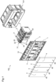
Figure 1 is an exploded perspective view of the modular control assembly according to the present invention, -
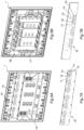
Figures 2 to 4 are perspective views illustrating a control module, a supply unit and an actuation unit, respectively, details of the modular control assembly inFigure 1 , -
Figure 5 is a perspective view of a support frame to which a power supply unit and two drive units are connected at a rear face, -
Figures 6A and 6B are a front and a rear perspective view, respectively, of the support frame inFigure 5 , without the connected units, -
Figures 7A and 7B are a front perspective view and a perspective view from the rear, respectively, of conductor means, a detail of the frame inFigures 6A and 6B , -
Figures 8A and 8B are two perspective views illustrating movable elements arranged respectively to cover the conductor means and in a position to leave them available. - Referring initially to
Figure 1 , a modular control assembly for a home automation system is referred to overall by thereference number 100. - As will be further illustrated below, the
assembly 100 of the present invention is intended to control and command the home automation system, thereby enabling operation by a user of one or more components in the home automation system. - In other words, the user, acting through the
assembly 100, will be able to interact with the home automation system, controlling the equipment or devices included in it. - For example, the
modular control assembly 100 can be used to switch a lighting point on or off by closing or opening an electrical contact for supplying a light bulb, or to control relays for activating electric motors, e.g. for operating roller shutters, or to send a control signal to a heating system. As mentioned earlier, the equipment/devices/systems controlled via themodular control assembly 100 will be generically referred to as electrical or electronic utilities. - The
assembly 100 is advantageously of the wall-installable type and, for this purpose, comprises asupport frame 1, preferably provided with attachment means 7 for its attachment to a built-ininstallation box 101. Such attachment means 7 may, for example, comprise a pair of screws intended to engage in respective seats made in thebox 101. - However, it will be appreciated that different attachment systems can be provided and the frame can be configured not only for wall mounting but also, more generically, to any installation box, e.g. intended to be placed on a table to control lights or other equipment from that position.
- In some preferred embodiments, the
support frame 1 has a flat shape, with a substantially rectangular extension, and definesmain faces - A
first face 1A is intended, in use, to face outwards from the wall on which theassembly 100 of the present invention is mounted. - A
second face 1B is instead intended to face the wall and, in particular, will face an internal volume of saidinstallation box 101. - At said
first face 1A, theassembly 100 has first connection means 5 configured to removably connect acontrol module 4 to thesupport frame 1 in a respectivefirst seat 16. - As will be explained in more detail below, the
control modules 4 are configured in such a way as to allow a user to command or control an electrical or electronic utility in the home automation system. - For this purpose, in some embodiments the
control modules 4 can have arespective actuation button 40, which can be operated in such a way as to generate an actuation signal that is sent via a communication bus of the home automation system to the respective user. - For example, the user can, by acting on the
actuation button 40, switch a light bulb on or off, rather than acting on the other components of the home automation system, as previously mentioned. - In the example shown in the figure, the
assembly 100 comprises fourseparate control modules 4, each possibly controlling a respective user. As can be seen, thecontrol modules 4 preferably have an elongated shape and extend parallel to the short sides of the rectangle defined by the frame, essentially along their entire length. - The assembly formed by the four control modules therefore allows the
entire face 1A of theframe 1 to be covered. - In preferred embodiments, the
control modules 4 comprise arespective fixing base 40A on which theactuation button 40 is supported in a tilting manner. - The user can therefore operate the
actuation button 40 with one finger by swinging a micro-switch, not shown in the figure, on the fixingbase 40. The micro-switch in turn will send an actuation signal to the utilities, as described in more detail below. - More generally, the
control module 4 is of the electromechanical type. - In some embodiments, the use of an electronic control module, e.g. fitted with a contact or proximity sensor, can also be envisaged, possibly combined with electromechanical modules.
- In order to allow recognition of the type of actuation realised by the
control module 4, and make visible the zones at which the user must act to switch thebutton 40, thecontrol module 4 may comprise a plurality of luminous elements, not shown in the figure. - Advantageously, the luminous elements, e.g. formed by LEDs, can be programmable in such a way as to display information relating to said electric or electronic utility and/or the operating condition of said electric or electronic utility.
- For example, the LEDs could form a luminous icon in the shape of an upwards or downwards arrow in the case of shutter actuation, or luminous zones identifying the position at which to act to switch a light point on or off.
- In order to enable the transmission of the actuation signal, and possibly a characteristic status signal from a user operating condition, the
assembly 100 additionally comprises at least oneactuation unit 2 and onepower supply unit 3. - The
actuation unit 2 is configured in such a way that it receives an actuation signal of the utility from the connection bus of the home automation system, and switches, as a function of the signal received, the electrical or electronic utility between at least a first status and a second status. - For this purpose, the
actuation unit 2 can comprise, in preferred embodiments, one or more relays and include respective terminals for the electrical connection of the signal generated by the relay to the respective utilities. - However, the actuation signal can also be transmitted via the communication bus of the home automation system to remote actuation units, i.e. located in other areas of the electrical system, or to specific relays that are also remotely located.
- For this purpose, the actuation unit can comprise
respective terminals - The
power supply unit 3, on the other hand, is responsible for supplying theactuation unit 2 with a bus connection signal and ground, as well as for receiving and transmitting data for the management of the home automation system, e.g. data configured to define a status signal characteristic of the operating condition of the electrical or electronic utility controlled by theassembly 100. - The
power supply unit 3 can also compriserespective terminals communication bus 31, through which the connection signal to the aforementioned bus is exchanged, one forground connection 32, one for thepower supply 33 of thecontrol modules 4. Preferred embodiments also include a pair ofterminals control modules 4. - In fact, it should be noted that the
control modules 4 use thepower supply unit 3 to communicate with the bus of the home automation system. - The
power supply unit 3 is also equipped with respective terminals configured to connect it to the communication bus of the home automation system, i.e. to enable communication with the other components thereof. - As can best be seen in the example of
Figures 6A-6B and 7A-7B , thesupport frame 1 also comprises conductor means 10 comprising a plurality ofcontacts - The conductor means 10 advantageously enable the connection of the terminals in the
actuation unit 2 andpower supply unit 3 to therespective terminals control module 4. - The terminals in the
control module 4 advantageously correspond to the terminals of the power supply and actuation unit. - There will therefore be a terminal 41 for supplying power to the
control unit 4, a terminal forground connection 42 and a pair ofterminals power supply unit 3. - Optionally, a
common terminal 45 can also be provided to enable direct communication between thedifferent control modules 4 mounted on thesupport frame 1. The latter terminal makes it possible, for example, to simultaneously illuminate all thecontrol modules 4 when specific operating situations occur. - The conductor means 10 advantageously comprise electrified tracks configured in such a way as to connect all terminals of the same type. Such electrified tracks, and more generally said conductor means 10, can be advantageously defined by a printed circuit.
- For example, in this way, each
control module 4 will be able to communicate with the units inassembly 100, as well as in the home automation system as a whole, enabling the sending and receiving of signals required for the operation of the home automation system. - It will be appreciated that the first conductor means 5 are also configured in such a way that, when the
control modules 4 are connected in their respective locations, theterminals control module 4 are connected to therespective contacts first face 1A. - Advantageously, the
actuation unit 2 and thepower supply unit 3 are connected at thesecond face 1B of thesupport frame 1, i.e. the opposite face to thefirst face 1A. - For this purpose, second connection means 6 can be provided which are configured in such a way that the
actuation unit 2 and thepower supply unit 3 are removably connected in a respectivesecond seat 17 defined in thesupport frame 1. - Also in this case, the connection means 6 advantageously allow the
respective terminals actuation unit 2 andrespective terminals power supply unit 3 to be connected to the correspondingcontacts 11', 12', 13', 14', 15'. - As can best be seen from
Figures 7A and 7B , the conductor means 10 are preferably in the form of a flat strip, which is supported on the structure of the support frame in such a way that the contacts extend between thefirst face 1A and thesecond face 1B. - Preferably, at the
second face 1B thesupport frame 1 comprises a plurality ofsecond seats 17 each configured to accommodate either anactuation unit 2 or apower supply unit 3, which will therefore be provided with the same connection means 6. - As illustrated in
Figure 6B , theseats 17 can be realised by means of a projecting frame 17A defined in thesecond face 1B. - Referring now to
Figures 8A and 8B , in some embodiments, theframe 1 comprises a series ofmovable elements 18 configured in such a way as to cover saidconductors 11', 12', 13', 14', 15' at saidsecond seat 17 in a first operating position and leave saidconductors 11', 12', 13', 14', 15' accessible in a second operating position. - Preferably said
movable element 18 is slidable at saidsecond face 1B. - Referring now to
figure 5 , in some embodiments the actuation unit may compriseauxiliary buttons 23 configured in such a way as to provide the actuation signal in the absence of thecontrol module 4. - On the
second face 1B throughopenings 19 are formed, configured in such a way as to make saidauxiliary buttons 23 accessible through said faces. - In this way, the
auxiliary buttons 23 can be reached by an installer and the home automation system can be controlled even in the absence of the control modules, e.g. during an installation phase of the home automation system.
Claims (15)
- Modular control assembly (100) for home automation system comprising:a support frame (1) fixable to a wall and/or to an installation box (101);at least one actuation unit (2) configured in such a way as to provide an actuation signal of an electrical utility to a connection bus of the home automation system, in such a way as to switch said electrical utility between at least a first status and a second status,a power supply unit (3) configured in such a way as to power said actuation unit (2),at least one control module (4) comprising an actuation button (40), operable in such a way as to generate an actuation signal,wherein said support frame (1) comprises conductor means (10) comprising a plurality of contacts (11, 12, 13, 14, 15) configured to power said control module and to transmit said actuation signal to said actuation unit,said modular control assembly (100) further comprising first connection means (5) configured to removably connect said control module to said support frame (1) in a respective first seat (16) defined in said support frame (1) and to connect respective terminals (41) of said control module (4) to one or more of said contacts (11, 12, 13, 14, 15).
- Modular control assembly (100) according to claim 1, wherein said support frame (1) comprises second connection means (6) configured in such a way as to removably connect said actuation unit (2) and/or said power supply unit (3) in a respective second seat (17) defined in said support frame (1) and to connect respective terminals (21) of said actuation unit (2) and/or respective terminals (31) of said power supply unit (3) to one or more of said contacts (11', 12', 13', 14', 15').
- Modular control assembly (100) according to any one of the preceding claims, wherein said support frame (1) has a flat shape and defines opposing main faces (1A, 1B), said control module (4) being connected at a first face (1A) of said main faces, said actuation unit (2) and said power supply unit (3) being connected at a second face (1B) of said main faces, opposite to said first face (1A).
- Modular control assembly (100) according to claims 2 and 3, wherein said second seat(s) (17) is/are realised by means of a projecting frame (17A) defined in said second face (1B).
- Modular control assembly (100) according to any one of the preceding claims, wherein said connection means are in the form of a flat strip, wherein said contacts extend between said first face (1A) and said second face (1B).
- Modular control assembly (100) according to the preceding claim, wherein said conductor means (10) are defined by a printed circuit.
- Modular control assembly (100) according to any one of the preceding claims, wherein said actuation unit comprises auxiliary buttons (23) configured in such a way as to provide said actuation signal in the absence of said control module (4).
- Modular control assembly (100) according to the preceding claim, wherein said second face (1B) is configured in such a way as to cover said actuation unit (2) and said power supply unit (3), said second face (1B) comprising through openings (19) configured in such a way as to make said auxiliary buttons (23) accessible through said faces.
- Modular control assembly (100) according to any one of the preceding claims, wherein said support frame (1) comprises a movable element (18) configured in such a way as to cover said conductors (11', 12', 13', 14', 15') at said second seat (17) in a first operating position and leave said conductors (11', 12', 13', 14', 15') accessible in a second operating position.
- Modular control assembly (100) according to the preceding claim, wherein said support frame (1) comprises a plurality of second seats (17) each configured in such a way as to house a respective unit selected between said actuation unit (2) and said power supply unit (3), said support frame (1) comprising a plurality of movable elements (18) each configured in such a way as to cover the conductors (11', 12', 13', 14', 15') of a respective seat of said plurality of second seats (17).
- Modular control assembly (100) according to claim 9 or 10, wherein said movable element (18) is slidable at said second face (1B).
- Modular control assembly (100) according to any one of the preceding claims, wherein said control module (4) comprises a fixing base (40A) on which said actuation button (40) is supported in a tilting manner, said control module (4) preferably comprising at least one micro-switch operable by oscillation of said actuation button (40) with respect to said fixing base (40A) .
- Modular control assembly (100) according to any one of the preceding claims, wherein said control module (4) comprises a plurality of luminous elements programmable in such a way as to display information relating to said electrical utility and/or to the operating condition of said electrical utility.
- Modular control assembly (100) according to any one of the preceding claims, wherein said first connection means (5) and/or said second connection means (6) comprise elastic elements (51, 61) that can be snap-fitted into respective housings (52, 62).
- Modular control assembly (100) according to any one of the preceding claims, wherein said one or more seats are formed by a projecting frame defined in said first face (1A).
Applications Claiming Priority (1)
| Application Number | Priority Date | Filing Date | Title |
|---|---|---|---|
| IT102023000010869A IT202300010869A1 (en) | 2023-05-29 | 2023-05-29 | MODULAR CONTROL GROUP FOR A HOME AUTOMATION SYSTEM |
Publications (3)
| Publication Number | Publication Date |
|---|---|
| EP4510162A1 true EP4510162A1 (en) | 2025-02-19 |
| EP4510162C0 EP4510162C0 (en) | 2026-03-04 |
| EP4510162B1 EP4510162B1 (en) | 2026-03-04 |
Family
ID=88097596
Family Applications (1)
| Application Number | Title | Priority Date | Filing Date |
|---|---|---|---|
| EP24191303.7A Active EP4510162B1 (en) | 2023-05-29 | 2024-07-26 | Modular control assembly for home automation system |
Country Status (2)
| Country | Link |
|---|---|
| EP (1) | EP4510162B1 (en) |
| IT (1) | IT202300010869A1 (en) |
Citations (3)
| Publication number | Priority date | Publication date | Assignee | Title |
|---|---|---|---|---|
| US4401864A (en) * | 1980-07-10 | 1983-08-30 | Olympus Optical Company Ltd. | Seesaw type switch mechanism |
| WO2021137130A1 (en) * | 2019-12-30 | 2021-07-08 | Bticino S.P.A. | Connection module and modular group for electrical and/or home automation systems |
| WO2021147130A1 (en) | 2020-01-21 | 2021-07-29 | 浙江绿源电动车有限公司 | Hub motor having built-in control system |
-
2023
- 2023-05-29 IT IT102023000010869A patent/IT202300010869A1/en unknown
-
2024
- 2024-07-26 EP EP24191303.7A patent/EP4510162B1/en active Active
Patent Citations (3)
| Publication number | Priority date | Publication date | Assignee | Title |
|---|---|---|---|---|
| US4401864A (en) * | 1980-07-10 | 1983-08-30 | Olympus Optical Company Ltd. | Seesaw type switch mechanism |
| WO2021137130A1 (en) * | 2019-12-30 | 2021-07-08 | Bticino S.P.A. | Connection module and modular group for electrical and/or home automation systems |
| WO2021147130A1 (en) | 2020-01-21 | 2021-07-29 | 浙江绿源电动车有限公司 | Hub motor having built-in control system |
Also Published As
| Publication number | Publication date |
|---|---|
| EP4510162C0 (en) | 2026-03-04 |
| IT202300010869A1 (en) | 2024-11-29 |
| EP4510162B1 (en) | 2026-03-04 |
Similar Documents
| Publication | Publication Date | Title |
|---|---|---|
| US11695419B2 (en) | Electrical switch | |
| EP1260886A2 (en) | Home automation system | |
| EP1450383A1 (en) | intelligent switch assembly and system | |
| CN101320896B (en) | Sensor unit | |
| WO2012141839A2 (en) | Method and apparatus for combining ac power relay and current sensors with ac wiring devices | |
| US5184278A (en) | Lighting control and emergy management system | |
| EP3354115A1 (en) | Plug load receptacle | |
| WO2021137130A1 (en) | Connection module and modular group for electrical and/or home automation systems | |
| EP4510162B1 (en) | Modular control assembly for home automation system | |
| EP2237646A1 (en) | Hook ceiling | |
| EP3248255B1 (en) | Interface module for powering wireless user interface through light switch | |
| EP3924990B1 (en) | Modular electronic device for electrical and/or home automation systems | |
| CN114203465A (en) | Switch with a switch body | |
| CN110914945A (en) | Electrical installation and additional functional module associated therewith | |
| US7238882B2 (en) | Low voltage door switch | |
| JP5588321B2 (en) | Load control switch and load control switch system | |
| CN110945614B (en) | Electrical equipment and its related additional function modules | |
| CN110915086B (en) | Electrical device and additional functional module associated therewith | |
| EP3035467B1 (en) | Control device of flush type for at least one electric user appliance | |
| US20260092713A1 (en) | Load control device for controlling an electrical load in response to sense an environmental characteristic | |
| EP4085499A1 (en) | Cover plate for electrical and/or home automation systems | |
| AU644563B2 (en) | Lighting control and energy management system | |
| HK1124135A (en) | Stackable thermostat |
Legal Events
| Date | Code | Title | Description |
|---|---|---|---|
| PUAI | Public reference made under article 153(3) epc to a published international application that has entered the european phase |
Free format text: ORIGINAL CODE: 0009012 |
|
| STAA | Information on the status of an ep patent application or granted ep patent |
Free format text: STATUS: THE APPLICATION HAS BEEN PUBLISHED |
|
| AK | Designated contracting states |
Kind code of ref document: A1 Designated state(s): AL AT BE BG CH CY CZ DE DK EE ES FI FR GB GR HR HU IE IS IT LI LT LU LV MC ME MK MT NL NO PL PT RO RS SE SI SK SM TR |
|
| STAA | Information on the status of an ep patent application or granted ep patent |
Free format text: STATUS: REQUEST FOR EXAMINATION WAS MADE |
|
| 17P | Request for examination filed |
Effective date: 20250819 |
|
| GRAP | Despatch of communication of intention to grant a patent |
Free format text: ORIGINAL CODE: EPIDOSNIGR1 |
|
| STAA | Information on the status of an ep patent application or granted ep patent |
Free format text: STATUS: GRANT OF PATENT IS INTENDED |
|
| INTG | Intention to grant announced |
Effective date: 20250926 |
|
| RIN1 | Information on inventor provided before grant (corrected) |
Inventor name: TURCATO, MARCO Inventor name: MANERA, RICCARDO |
|
| GRAS | Grant fee paid |
Free format text: ORIGINAL CODE: EPIDOSNIGR3 |
|
| GRAA | (expected) grant |
Free format text: ORIGINAL CODE: 0009210 |
|
| STAA | Information on the status of an ep patent application or granted ep patent |
Free format text: STATUS: THE PATENT HAS BEEN GRANTED |
|
| AK | Designated contracting states |
Kind code of ref document: B1 Designated state(s): AL AT BE BG CH CY CZ DE DK EE ES FI FR GB GR HR HU IE IS IT LI LT LU LV MC ME MK MT NL NO PL PT RO RS SE SI SK SM TR |
|
| REG | Reference to a national code |
Ref country code: CH Ref legal event code: F10 Free format text: ST27 STATUS EVENT CODE: U-0-0-F10-F00 (AS PROVIDED BY THE NATIONAL OFFICE) Effective date: 20260304 Ref country code: GB Ref legal event code: FG4D |
|
| REG | Reference to a national code |
Ref country code: IE Ref legal event code: FG4D |
|
| REG | Reference to a national code |
Ref country code: DE Ref legal event code: R096 Ref document number: 602024002964 Country of ref document: DE |
|
| U01 | Request for unitary effect filed |
Effective date: 20260403 |
|
| U07 | Unitary effect registered |
Designated state(s): AT BE BG DE DK EE FI FR IT LT LU LV MT NL PT RO SE SI Effective date: 20260416 |
|
| PG25 | Lapsed in a contracting state [announced via postgrant information from national office to epo] |
Ref country code: RS Free format text: LAPSE BECAUSE OF FAILURE TO SUBMIT A TRANSLATION OF THE DESCRIPTION OR TO PAY THE FEE WITHIN THE PRESCRIBED TIME-LIMIT Effective date: 20260604 |
|
| PG25 | Lapsed in a contracting state [announced via postgrant information from national office to epo] |
Ref country code: ES Free format text: LAPSE BECAUSE OF FAILURE TO SUBMIT A TRANSLATION OF THE DESCRIPTION OR TO PAY THE FEE WITHIN THE PRESCRIBED TIME-LIMIT Effective date: 20260304 |
|
| PG25 | Lapsed in a contracting state [announced via postgrant information from national office to epo] |
Ref country code: PL Free format text: LAPSE BECAUSE OF FAILURE TO SUBMIT A TRANSLATION OF THE DESCRIPTION OR TO PAY THE FEE WITHIN THE PRESCRIBED TIME-LIMIT Effective date: 20260304 |
|
| PG25 | Lapsed in a contracting state [announced via postgrant information from national office to epo] |
Ref country code: GR Free format text: LAPSE BECAUSE OF FAILURE TO SUBMIT A TRANSLATION OF THE DESCRIPTION OR TO PAY THE FEE WITHIN THE PRESCRIBED TIME-LIMIT Effective date: 20260605 |
|
| PG25 | Lapsed in a contracting state [announced via postgrant information from national office to epo] |
Ref country code: NO Free format text: LAPSE BECAUSE OF FAILURE TO SUBMIT A TRANSLATION OF THE DESCRIPTION OR TO PAY THE FEE WITHIN THE PRESCRIBED TIME-LIMIT Effective date: 20260604 |
|
| PG25 | Lapsed in a contracting state [announced via postgrant information from national office to epo] |
Ref country code: HR Free format text: LAPSE BECAUSE OF FAILURE TO SUBMIT A TRANSLATION OF THE DESCRIPTION OR TO PAY THE FEE WITHIN THE PRESCRIBED TIME-LIMIT Effective date: 20260304 |
|
| U20 | Renewal fee for the european patent with unitary effect paid |
Year of fee payment: 3 Effective date: 20260622 |