EP4510151A2 - Electronic enclosure with neutron shield for nuclear in-core applications - Google Patents
Electronic enclosure with neutron shield for nuclear in-core applications Download PDFInfo
- Publication number
- EP4510151A2 EP4510151A2 EP24216074.5A EP24216074A EP4510151A2 EP 4510151 A2 EP4510151 A2 EP 4510151A2 EP 24216074 A EP24216074 A EP 24216074A EP 4510151 A2 EP4510151 A2 EP 4510151A2
- Authority
- EP
- European Patent Office
- Prior art keywords
- neutron
- enclosure
- layer
- cavity
- electronic components
- Prior art date
- Legal status (The legal status is an assumption and is not a legal conclusion. Google has not performed a legal analysis and makes no representation as to the accuracy of the status listed.)
- Pending
Links
Images


Classifications
-
- G—PHYSICS
- G21—NUCLEAR PHYSICS; NUCLEAR ENGINEERING
- G21C—NUCLEAR REACTORS
- G21C3/00—Reactor fuel elements and their assemblies; Selection of substances for use as reactor fuel elements
- G21C3/02—Fuel elements
- G21C3/04—Constructional details
- G21C3/16—Details of the construction within the casing
-
- G—PHYSICS
- G21—NUCLEAR PHYSICS; NUCLEAR ENGINEERING
- G21C—NUCLEAR REACTORS
- G21C3/00—Reactor fuel elements and their assemblies; Selection of substances for use as reactor fuel elements
- G21C3/02—Fuel elements
- G21C3/04—Constructional details
- G21C3/06—Casings; Jackets
- G21C3/10—End closures ; Means for tight mounting therefor
-
- G—PHYSICS
- G21—NUCLEAR PHYSICS; NUCLEAR ENGINEERING
- G21F—PROTECTION AGAINST X-RADIATION, GAMMA RADIATION, CORPUSCULAR RADIATION OR PARTICLE BOMBARDMENT; TREATING RADIOACTIVELY CONTAMINATED MATERIAL; DECONTAMINATION ARRANGEMENTS THEREFOR
- G21F1/00—Shielding characterised by the composition of the materials
-
- G—PHYSICS
- G21—NUCLEAR PHYSICS; NUCLEAR ENGINEERING
- G21F—PROTECTION AGAINST X-RADIATION, GAMMA RADIATION, CORPUSCULAR RADIATION OR PARTICLE BOMBARDMENT; TREATING RADIOACTIVELY CONTAMINATED MATERIAL; DECONTAMINATION ARRANGEMENTS THEREFOR
- G21F1/00—Shielding characterised by the composition of the materials
- G21F1/02—Selection of uniform shielding materials
- G21F1/08—Metals; Alloys; Cermets, i.e. sintered mixtures of ceramics and metals
-
- G—PHYSICS
- G21—NUCLEAR PHYSICS; NUCLEAR ENGINEERING
- G21F—PROTECTION AGAINST X-RADIATION, GAMMA RADIATION, CORPUSCULAR RADIATION OR PARTICLE BOMBARDMENT; TREATING RADIOACTIVELY CONTAMINATED MATERIAL; DECONTAMINATION ARRANGEMENTS THEREFOR
- G21F1/00—Shielding characterised by the composition of the materials
- G21F1/12—Laminated shielding materials
-
- G—PHYSICS
- G21—NUCLEAR PHYSICS; NUCLEAR ENGINEERING
- G21F—PROTECTION AGAINST X-RADIATION, GAMMA RADIATION, CORPUSCULAR RADIATION OR PARTICLE BOMBARDMENT; TREATING RADIOACTIVELY CONTAMINATED MATERIAL; DECONTAMINATION ARRANGEMENTS THEREFOR
- G21F1/00—Shielding characterised by the composition of the materials
- G21F1/12—Laminated shielding materials
- G21F1/125—Laminated shielding materials comprising metals
-
- G—PHYSICS
- G21—NUCLEAR PHYSICS; NUCLEAR ENGINEERING
- G21F—PROTECTION AGAINST X-RADIATION, GAMMA RADIATION, CORPUSCULAR RADIATION OR PARTICLE BOMBARDMENT; TREATING RADIOACTIVELY CONTAMINATED MATERIAL; DECONTAMINATION ARRANGEMENTS THEREFOR
- G21F3/00—Shielding characterised by its physical form, e.g. granules, or shape of the material
-
- G—PHYSICS
- G21—NUCLEAR PHYSICS; NUCLEAR ENGINEERING
- G21C—NUCLEAR REACTORS
- G21C17/00—Monitoring; Testing ; Maintaining
- G21C17/10—Structural combination of fuel element, control rod, reactor core, or moderator structure with sensitive instruments, e.g. for measuring radioactivity, strain
- G21C17/102—Structural combination of fuel element, control rod, reactor core, or moderator structure with sensitive instruments, e.g. for measuring radioactivity, strain the sensitive element being part of a fuel element or a fuel assembly
-
- G—PHYSICS
- G21—NUCLEAR PHYSICS; NUCLEAR ENGINEERING
- G21C—NUCLEAR REACTORS
- G21C3/00—Reactor fuel elements and their assemblies; Selection of substances for use as reactor fuel elements
- G21C3/02—Fuel elements
- G21C3/04—Constructional details
- G21C3/16—Details of the construction within the casing
- G21C3/18—Internal spacers or other non-active material within the casing, e.g. compensating for expansion of fuel rods or for compensating excess reactivity
-
- G—PHYSICS
- G21—NUCLEAR PHYSICS; NUCLEAR ENGINEERING
- G21C—NUCLEAR REACTORS
- G21C3/00—Reactor fuel elements and their assemblies; Selection of substances for use as reactor fuel elements
- G21C3/02—Fuel elements
- G21C3/04—Constructional details
- G21C3/16—Details of the construction within the casing
- G21C3/20—Details of the construction within the casing with coating on fuel or on inside of casing; with non-active interlayer between casing and active material with multiple casings or multiple active layers
-
- Y—GENERAL TAGGING OF NEW TECHNOLOGICAL DEVELOPMENTS; GENERAL TAGGING OF CROSS-SECTIONAL TECHNOLOGIES SPANNING OVER SEVERAL SECTIONS OF THE IPC; TECHNICAL SUBJECTS COVERED BY FORMER USPC CROSS-REFERENCE ART COLLECTIONS [XRACs] AND DIGESTS
- Y02—TECHNOLOGIES OR APPLICATIONS FOR MITIGATION OR ADAPTATION AGAINST CLIMATE CHANGE
- Y02E—REDUCTION OF GREENHOUSE GAS [GHG] EMISSIONS, RELATED TO ENERGY GENERATION, TRANSMISSION OR DISTRIBUTION
- Y02E30/00—Energy generation of nuclear origin
- Y02E30/30—Nuclear fission reactors
Definitions
- the invention relates to enclosures for use in nuclear fuel rods to shield in-core electronic components.
- Sensors are placed in and around nuclear reactors to monitor conditions within the reactor. Tests have shown that some electronic sensors, such as non-organic capacitors, inductors, and surge arrestor gas discharge tubes, will operate at conditions equivalent to the elevated temperatures and radiation environments found in pressurized water reactors (PWR), but that the long term stability and drift of their operating parameters degrade over time. For example, a capacitor's capacitance, an inductor's inductance, or a gas discharge tube's break down voltage will degrade under the conditions present in nuclear reactors.
- PWR pressurized water reactors
- the sensors placed in reactors are exposed to ionizing radiation from both neutrons and gamma radiation. Over time, the radiation will interact with the materials in the electronic components of the sensors to impact performance and in many cases cause damage to the sensors.
- the effects of gamma radiation have been found to be predominantly transient in nature or only present when the irradiation field is present and cumulative damage to the microstructure is minimal.
- the effect of neutron exposure produces damage cascades of permanent voids and interstitials within the material and in some cases cause transmutation reactions to occur.
- the effects of the neutrons on the material used in sensors are both permanent and cumulative, whereas the effects of gamma irradiation are predominantly short lived and non-cumulative.
- the damaging effects of neutron exposure described above can be significantly delayed or reduced, if not avoided entirely, by enclosing the non-organic components of sensors necessary to the operation and monitoring of a nuclear reactor within an electronic enclosure equipped with a neutron shield as described herein. Having such a neutron shield will stabilize the performance of the sensors and slow down the long term degradation of the components due to neutron interactions.
- the enclosure would reside within the inner diameter of a typical nuclear fuel rod.
- the enclosure would be able to withstand neutron flux levels typically seen in the core of a commercial PWR reactor.
- the enclosure should withstand temperatures greater than 350°C.
- an electronics enclosure having neutron shielding properties will enable real time data recovery during testing of new fuel and cladding designs and in actual operation of nuclear reactors.
- the electronics enclosure with neutron shielding properties described herein may isolate the electronic components from electrically conductive fuel rods.
- the electronics enclosure with neutron shielding properties described herein may provide the opportunity to shield non-organic electronics from neutrons and extend the time required to reach a target fluence.
- An enclosure for non-organic electronic components includes a supporting structure that defines an inner cavity for housing non-organic electronic components, and a neutron barrier formed from neutron reflecting materials and neutron absorbing materials.
- the neutron barrier shields the electronic components when the components are housed in the cavity from neutrons, such as those generated in a nuclear reactor core.
- the neutron barrier may comprise a solid neutron reflecting layer surrounding the neutron absorbing material, and in certain aspects, the solid neutron reflecting layer may be the supporting structure.
- the neutron absorbing material may be in the form of a solid inner layer adjacent to and surrounding the cavity, being positioned in between the solid neutron reflecting layer and the cavity. Alternatively, the neutron absorbing material may be in the form of a powder filling the cavity and, in use, surrounding the electronic components.
- the supporting structure may be an outer structural layer made of a neutron transparent material, such as a solid ceramic material that neither reflects nor absorbs neutrons.
- the supporting structure may surround a solid neutron reflecting layer, which in turn may surround either a solid neutron absorbing material that surrounds the cavity, or a powdered neutron absorbing material within the cavity.
- the supporting structure may surround the cavity and the neutron barrier may be comprised of neutron reflecting material and neutron absorbing material in the form of powders contained within the cavity.
- the neutron reflecting and neutron absorbing powders may form a mixture filling the cavity and, in use, surrounding the electronic components.
- the neutron reflecting powder and the neutron absorbing powder may be disposed in layers, wherein the neutron absorbing powder layer is disposed adjacent to and surrounding the cavity and the neutron reflecting powder layer is disposed between the solid ceramic supporting structure and the neutron absorbing powder layer.
- the neutron reflecting powder and the neutron absorbing powder may be disposed in multiple alternating layers within the cavity.
- the neutron reflecting powder may be disposed in a layer in the cavity adjacent to the solid ceramic layer and the neutron absorbing powder may fill the cavity and in use, surround the electronic components.
- An embodiment of the enclosure described herein may be for use in a nuclear fuel rod wherein the fuel rod has a section for containing nuclear fuel.
- the enclosure includes an outer structural layer defining an inner cavity for receiving, in use, non-organic electronic components, a neutron barrier disposed between the structural layer and the cavity, the neutron barrier comprising at least one neutron reflecting layer and at least one neutron absorbing layer, and a forward neutron absorbing layer positioned between the section for containing nuclear fuel and the cavity.
- any numerical range recited herein is intended to include all sub-ranges subsumed therein.
- a range of "1 to 10" is intended to include any and all sub-ranges between (and including) the recited minimum value of 1 and the recited maximum value of 10, that is, having a minimum value equal to or greater than 1 and a maximum value of equal to or less than 10.
- Sensitive electronic components needed in nuclear fuel assemblies may be protected from exposure to neutrons by enclosing the components in an electronics enclosure 10 equipped with a neutron barrier 20 according to the various embodiments described herein.
- an embodiment of the electronics enclosure 10 includes an enclosure body 14 and a lid 12.
- An internal cavity 18 houses non-organic sensors and other electronic components (not shown) critical for various instrumentation and measurement applications.
- the sensors may include, for example, transmitters, capacitors, and detectors for measuring environmental conditions, such as in-core radioactivity sensors, thermocouple sensors, temperature sensors, pressure sensors and the like.
- the cavity 18 may be made into any shape best suited to house the particular non-organic components to be placed in the enclosure 10.
- the cavity 18, as shown in Figure 1A-1C may include one or more separate compartments 32 of a different size to accommodate different components.
- the compartments 32 may be separated from cavity 18 by a wall 34 or may be continuous.
- Cavity 18 also includes passages 28 and 36 through which wires for the electronic components may pass out of and through the enclosure 10, respectively.
- Lid 12 may include threaded holes 30 leading into cavity 18 for placement of screws (not shown) to hold the electronics in place within the cavity 18 to prevent movement or shifting of the electronic components.
- lid 12 is attached to body 14 with screws or other fasteners 16.
- cavity 18 may be one single cavity of uniform or non-uniform dimensions.
- enclosure 10 is made of a ceramic based material.
- the enclosure 10 is designed to fit within the inner diameter of a nuclear fuel rod 40 and preferably positioned axially near the top of the fuel rod 40 in the upper plenum region, as shown in Figure 5 .
- the electronic enclosure 10 also includes a neutron barrier 20 surrounding the electronic components.
- Neutron barrier 20 includes a neutron reflecting material and a neutron absorbing material.
- the neutron reflecting material 22 When a neutron interacts with the electronic enclosure 10, the neutron reflecting material 22 will act as the first layer of the neutron barrier 20 to shield the electronic components from neutrons.
- Beryllium Oxide (BeO) for example, is suitable as the neutron reflecting material because it has very low thermal and fast nuclear absorption cross sections but a relatively high scattering cross section. When neutrons interact with BeO the majority will scatter elastically away from the sensitive electronics. Many neutrons will be reflected back into the moderator.
- a moderator as used herein, means the material that surrounds the fuel rod and thermalizes, or slows down, the neutrons. In a pressurized water reactor, for example, the moderator is water.
- the neutron absorbing material 24 provides the second layer of the neutron barrier 20 to shield the electronic components from neutrons.
- Gadolinium (Gd) containing materials are examples of suitable neutron absorbing materials. Gadolinium in the form of gadolinium oxide or gadolinium isotopes Gd-155 and Gd-157 have the highest neutron capture rate of any stable isotope with thermal absorption cross-sections of 61,000 and 254,000 barns respectively. These materials will be very effective at absorbing thermal neutrons and protecting the sensitive electronics.
- BeO and Gd 2 O 3 are not required for the neutron reflecting and neutron absorbing materials and are listed as examples only. There are other commercially available ceramics with highly reflective and absorptive properties.
- neutron reflecting materials useful in the neutron barrier 20 include beryllium, beryllium oxides, beryllium nitrides or beryllium carbides.
- neutron absorbing materials include gadolinium metals, gadolinium oxides, gadolinium isotopes, ceramic compounds of gadolinium, cadmium metals, cadmium oxides, born metals, boron oxides, hafnium metals, hafnium oxides, etc.
- the materials are most preferably made of the ceramic forms of the base materials to ensure high temperature operation and also to act as an electrical insulation barrier for the conductive electronics.
- the structural support 26 may be made of a neutron transparent material that is neither a neutron reflecting nor a neutron absorbing material.
- the neutron transparent material may be a ceramic material, and may preferably be made of alumina (Al 2 O 3 ).
- the enclosure body 14 may be formed from a structural support 26 and one or more neutron barrier layers.
- the neutron barrier 20 may be formed from a solid neutron reflective layer 22 that surrounds a solid neutron absorbing layer 24. Both surround cavity 18.
- neutron reflective layer 22 may provide the structural support and an additional or separate support structure 26 may be eliminated.
- Figure 2 illustrates a configuration for the neutron barrier 20 wherein the neutron reflecting layer 22 and the neutron absorbing layer 24 act both as the structural support and the neutron shield for the electronic enclosure 10.
- the solid neutron reflective layer 22 may alone function as the structural support to give enclosure body 14 its solid structure.
- enclosure body 14 comprises the solid neutron reflective layer 22 surrounding the solid neutron absorbing layer 24.
- the neutron reflecting layer may be made of beryllium or a beryllium containing compound, such as beryllium oxide (BeO).
- the neutron absorbing layer may be made of gadolinium or a gadolinium containing compound, such as gadolinium oxide (Gd 2 O 3 ).
- FIG 3 schematically illustrates an alternative embodiment of enclosure 10 wherein the outermost layer is a structural support 26, made of a neutron transparent material, such as a ceramic material.
- the ceramic material used for support structure 26 may be alumina.
- the use of alumina is well understood in nuclear applications and will provide either primary structural support or additional structural support for enclosure 10.
- the structural support 26 surrounds a solid neutron reflective layer 22 which in turn surrounds a solid neutron absorbing layer 24, which surrounds cavity 18.
- the neutron absorbing material 24 may be in the form of a powder which fills the spaces in cavity 18 that remain after the electronics components are inserted into the cavity 18.
- a neutron absorbing material 24 in powdered form is packed into cavity 18 and any other cavities 32 or passages 28 and 36 to fill any voids not filled by the electronics.
- Figure 4 schematically illustrates a configuration of enclosure 10 having, for example, an alumina (Al 2 O 3 ) ceramic structural support 26 surrounding a solid neutron reflecting layer 22 which surrounds a cavity 18 filled with a neutron absorbing material 24 in powder form.
- the powdered neutron absorbing material 24 may be in the form of pressed powdered layer lining the interior of cavity 18 surrounding the electronic components.
- the reflecting and absorbing layers may both be in powdered form surrounded by a non-reflecting, non-absorbing structural support 26.
- a non-reflecting, non-absorbing structural support 26 For example, both BeO and Gd 2 O 3 are available in powder form.
- the powders may be in the form of a homogenous mixture or may be in the form of pressed powdered layers, with alternating layers of at least one layer of each of the neutron reflecting and absorbing materials 22, 24.
- Figure 5 illustrates one configuration of enclosure 10 wherein neutron barrier 20 is in powdered form packed around the sensitive electronics (not shown).
- a solid reflecting layer 22 comprising a first part of neutron barrier 20 may act as the support structure 26 and surround cavity 18.
- the neutron absorbing material comprising a second part of the neutron barrier 20 may be in the form of a powder packed around the electronic components and filling spaces in cavity 18 not occupied by the electronic components, such as the wire passages 36 and 28.
- the powdered neutron absorbing material 24 may be in the form of pressed powdered layer lining the interior of cavity 18 surrounding the electronic components.
- FIG. 5 there may be at least two neutron absorbing layers in different positions within enclosure 10.
- An initial or forward neutron absorbing layer 38 is shown.
- the forward neutron absorbing layer 38 may provide an initial shield against neutrons coming from the nuclear fuel rod 40.
- the forward neutron absorbing layer 38 may be placed below the electronics cavity 18 between the center of the reactor core and the sensitive electronics. It is understood that neutrons in the plenum region of a nuclear fuel rod 40 will come from all directions but will have an upward bias, in the direction shown by arrow 46.
- enclosure 10 shields the electronics from neutrons that come from the center of the core that have this upward bias.
- the placement of the forward neutron absorbing layer 38 in the path of the neutron flow will cast a "neutron shadow" 44 over the electronics as illustrated in Figure 5 , absorbing neutrons that might otherwise have been directed toward the area of the shadow 44.
- the forward neutron absorbing layer 38 may be a block of a solid material, such as a gadolinium containing material or any of the neutron absorbing materials discussed above. As stated above, gadolinium oxide is only one of several materials that may be used in the neutron barrier 20. Gd metal (or another material with a high neutron cross section) may be used as the forward neutron absorbing layer 38.
- a benefit from forward neutron absorbing layer 38 is that it can be made thicker than the absorbing layer forming part of the enclosure 10 or packed in the cavity 18. The thicker layer 38 will therefore be able to absorb more neutrons.
- the neutron barrier 20 can be made from electrically conductive metal, such as cadmium, boron, hafnium, and gadolinium, without shorting any of the electronics because it can be separated from the components.
- Example 1 An enclosure for non-organic electronic components comprising:
- Example 2 The enclosure of example 1 wherein the neutron barrier is comprised of a solid neutron reflecting layer surrounding the neutron absorbing material.
- Example 3 The enclosure of example 2 wherein the solid neutron reflecting layer is the supporting structure.
- Example 4 The enclosure of example 3 wherein the neutron absorbing material comprises a solid inner layer adjacent to and surrounding the cavity.
- Example 5 The enclosure of example 3 wherein the neutron absorbing material comprises a powder filling the cavity and, in use, surrounding the electronic components.
- Example 6 The enclosure of example 2 wherein the supporting structure is a neutron transparent material surrounding the solid neutron reflecting layer.
- Example 7 The enclosure of example 6 wherein the neutron absorbing material comprises a solid inner layer adjacent to and surrounding the cavity.
- Example 8 The enclosure of example 6 wherein the neutron absorbing material comprises a powder filling the cavity and, in use, surrounding the electronic components.
- Example 9 The enclosure of example 1 wherein the supporting structure is a solid neutron transparent material; and the neutron reflecting material and the neutron absorbing material comprise powders contained within the inner cavity.
- Example 10 The enclosure of example 9 wherein the neutron reflecting and neutron absorbing powders form a mixture filling the cavity and, in use, surrounding the electronic components.
- Example 11 The enclosure of example 9 wherein the neutron reflecting powder and the neutron absorbing powder are disposed in layers, the neutron absorbing powder layer disposed adjacent to and surrounding the cavity and the neutron reflecting powder layer disposed between the solid ceramic layer and the neutron absorbing powder layer.
- Example 12 The enclosure of example 9 wherein the neutron reflecting powder and the neutron absorbing powder are disposed in multiple alternating layers.
- Example 13 The enclosure of example 9 wherein the neutron reflecting powder is disposed in a layer adjacent to the solid neutron transparent layer and the neutron absorbing powder fills the cavity and, in use, surrounds the electronic components.
- Example 14 The enclosure of example 9 wherein the supporting structure is formed from alumina.
- Example 15 The enclosure of example 1 wherein the neutron reflecting material comprises beryllium or a beryllium containing ceramic compound.
- Example 16 The enclosure of example 1 wherein the neutron absorbing material comprises gadolinium or a gadolinium containing ceramic compound.
- Example 17 The enclosure of example 1 wherein the neutron absorbing material is selected from the group consisting of gadolinium, cadmium, boron, hafnium, ceramic compounds containing of one or more of gadolinium, cadmium, boron, and hafnium, metal compounds containing gadolinium, and combinations thereof.
- the neutron absorbing material is selected from the group consisting of gadolinium, cadmium, boron, hafnium, ceramic compounds containing of one or more of gadolinium, cadmium, boron, and hafnium, metal compounds containing gadolinium, and combinations thereof.
- Example 18 The enclosure of example 1 wherein the enclosure has a bottom end and an upper end and further comprising a block of the neutron absorbing material positioned between the bottom end and the cavity.
- Example 19 An enclosure for non-organic electronic components for use in a nuclear fuel rod wherein the fuel rod has a section for containing nuclear fuel comprising:
- Example 20 The enclosure of example 19 wherein the outer structural layer comprises an exterior alumina layer.
- Example 21 The enclosure of example 19 wherein the neutron reflecting layer comprises beryllium or a beryllium containing ceramic compound.
- Example 22 The enclosure of example 19 wherein the neutron barrier comprises a mixture of a powdered neutron reflecting material and a powdered neutron absorbing material disposed within the cavity in a sufficient volume to fill the cavity and surround, in use, the electronic components.
- the neutron barrier comprises a mixture of a powdered neutron reflecting material and a powdered neutron absorbing material disposed within the cavity in a sufficient volume to fill the cavity and surround, in use, the electronic components.
- Example 23 The enclosure of example 19 wherein the neutron barrier comprises a layer of a powdered neutron reflecting material and a layer of a powdered neutron absorbing material, wherein the layer of neutron reflecting material is positioned adjacent to and in contact with the structural layer and the layer of the neutron absorbing material is positioned between the neutron reflecting material and the cavity.
- the neutron barrier comprises a layer of a powdered neutron reflecting material and a layer of a powdered neutron absorbing material, wherein the layer of neutron reflecting material is positioned adjacent to and in contact with the structural layer and the layer of the neutron absorbing material is positioned between the neutron reflecting material and the cavity.
- Example 24 The enclosure of example 19 wherein the neutron barrier comprises a layer of a powdered neutron reflecting material positioned adjacent to and in contact with the structural layer and a powdered neutron absorbing material disposed within the cavity in a sufficient volume to fill the cavity and surround, in use, the electronic components.
- Example 25 The enclosure of example 19 wherein the neutron absorbing material of the neutron barrier and the forward neutron absorbing layer are the same or different and each is selected from the group consisting of gadolinium, cadmium, boron, hafnium, ceramic compounds containing of one or more of gadolinium, cadmium, boron, and hafnium, metal compounds containing gadolinium, and combinations thereof.
Landscapes
- Engineering & Computer Science (AREA)
- Physics & Mathematics (AREA)
- General Engineering & Computer Science (AREA)
- High Energy & Nuclear Physics (AREA)
- Plasma & Fusion (AREA)
- Ceramic Engineering (AREA)
- Metallurgy (AREA)
- Measurement Of Radiation (AREA)
- Analysing Materials By The Use Of Radiation (AREA)
- Monitoring And Testing Of Nuclear Reactors (AREA)
- Shielding Devices Or Components To Electric Or Magnetic Fields (AREA)
- Health & Medical Sciences (AREA)
- Life Sciences & Earth Sciences (AREA)
- Biomedical Technology (AREA)
- General Health & Medical Sciences (AREA)
- Molecular Biology (AREA)
- Radiation-Therapy Devices (AREA)
Abstract
Description
- The invention relates to enclosures for use in nuclear fuel rods to shield in-core electronic components.
- Sensors are placed in and around nuclear reactors to monitor conditions within the reactor. Tests have shown that some electronic sensors, such as non-organic capacitors, inductors, and surge arrestor gas discharge tubes, will operate at conditions equivalent to the elevated temperatures and radiation environments found in pressurized water reactors (PWR), but that the long term stability and drift of their operating parameters degrade over time. For example, a capacitor's capacitance, an inductor's inductance, or a gas discharge tube's break down voltage will degrade under the conditions present in nuclear reactors.
- The sensors placed in reactors are exposed to ionizing radiation from both neutrons and gamma radiation. Over time, the radiation will interact with the materials in the electronic components of the sensors to impact performance and in many cases cause damage to the sensors. The effects of gamma radiation, however, have been found to be predominantly transient in nature or only present when the irradiation field is present and cumulative damage to the microstructure is minimal. The effect of neutron exposure produces damage cascades of permanent voids and interstitials within the material and in some cases cause transmutation reactions to occur. The effects of the neutrons on the material used in sensors are both permanent and cumulative, whereas the effects of gamma irradiation are predominantly short lived and non-cumulative.
- There is a need, therefore, to protect electronic components in sensors used in nuclear reactors from the effects of neutron exposure.
- The following summary is provided to facilitate an understanding of some of the innovative features unique to the embodiments disclosed and is not intended to be a full description. A full appreciation of the various aspects of the embodiments can be gained by taking the entire specification, claims, and abstract as a whole.
- The damaging effects of neutron exposure described above can be significantly delayed or reduced, if not avoided entirely, by enclosing the non-organic components of sensors necessary to the operation and monitoring of a nuclear reactor within an electronic enclosure equipped with a neutron shield as described herein. Having such a neutron shield will stabilize the performance of the sensors and slow down the long term degradation of the components due to neutron interactions. For optimum function, in various aspects, the enclosure would reside within the inner diameter of a typical nuclear fuel rod. In various aspects, the enclosure would be able to withstand neutron flux levels typically seen in the core of a commercial PWR reactor. In various aspects, the enclosure should withstand temperatures greater than 350°C.
- An electronics enclosure having neutron shielding properties according to any of the embodiments described herein will enable real time data recovery during testing of new fuel and cladding designs and in actual operation of nuclear reactors. In various aspects, the electronics enclosure with neutron shielding properties described herein may isolate the electronic components from electrically conductive fuel rods. In various aspects, the electronics enclosure with neutron shielding properties described herein may provide the opportunity to shield non-organic electronics from neutrons and extend the time required to reach a target fluence.
- An enclosure for non-organic electronic components according to various aspects includes a supporting structure that defines an inner cavity for housing non-organic electronic components, and a neutron barrier formed from neutron reflecting materials and neutron absorbing materials. The neutron barrier shields the electronic components when the components are housed in the cavity from neutrons, such as those generated in a nuclear reactor core.
- The neutron barrier may comprise a solid neutron reflecting layer surrounding the neutron absorbing material, and in certain aspects, the solid neutron reflecting layer may be the supporting structure. The neutron absorbing material may be in the form of a solid inner layer adjacent to and surrounding the cavity, being positioned in between the solid neutron reflecting layer and the cavity. Alternatively, the neutron absorbing material may be in the form of a powder filling the cavity and, in use, surrounding the electronic components.
- In certain aspects, the supporting structure may be an outer structural layer made of a neutron transparent material, such as a solid ceramic material that neither reflects nor absorbs neutrons.
- In various aspects, the supporting structure may surround a solid neutron reflecting layer, which in turn may surround either a solid neutron absorbing material that surrounds the cavity, or a powdered neutron absorbing material within the cavity.
- In alternative aspects, the supporting structure may surround the cavity and the neutron barrier may be comprised of neutron reflecting material and neutron absorbing material in the form of powders contained within the cavity. The neutron reflecting and neutron absorbing powders may form a mixture filling the cavity and, in use, surrounding the electronic components. In certain aspects, the neutron reflecting powder and the neutron absorbing powder may be disposed in layers, wherein the neutron absorbing powder layer is disposed adjacent to and surrounding the cavity and the neutron reflecting powder layer is disposed between the solid ceramic supporting structure and the neutron absorbing powder layer.
- In certain aspects, the neutron reflecting powder and the neutron absorbing powder may be disposed in multiple alternating layers within the cavity.
- In certain aspects, the neutron reflecting powder may be disposed in a layer in the cavity adjacent to the solid ceramic layer and the neutron absorbing powder may fill the cavity and in use, surround the electronic components.
- An embodiment of the enclosure described herein may be for use in a nuclear fuel rod wherein the fuel rod has a section for containing nuclear fuel. The enclosure includes an outer structural layer defining an inner cavity for receiving, in use, non-organic electronic components, a neutron barrier disposed between the structural layer and the cavity, the neutron barrier comprising at least one neutron reflecting layer and at least one neutron absorbing layer, and a forward neutron absorbing layer positioned between the section for containing nuclear fuel and the cavity.
- The characteristics and advantages of the present disclosure may be better understood by reference to the accompanying figures.
-
Figure 1A shows an embodiment of a form of the electronic enclosure described herein. -
Figure 1B shows a section view along the line A-A of the embodiment of the electronic enclosure shown inFigure 1A . -
Figure 1C shows a section view along the line B-B of the embodiment of the electronic enclosure shown inFigure 1A . -
Figure 2 is a schematic illustration of an embodiment of the electronics enclosure showing a neutron barrier functioning as the support structure with a solid neutron reflective layer and a solid neutron absorbing layer surrounding the electronics cavity. -
Figure 3 is a schematic illustration of a distinct solid support structure surrounding the solid neutron reflective and absorbing barrier layers ofFigure 2 . -
Figure 4 is a schematic illustration of an embodiment of the electronics enclosure showing a solid support structure formed from a neutron transparent material surrounding a neutron barrier having a solid reflecting barrier surrounding an electronics cavity filled with a neutron absorbing material in powdered form to fill those spaces in the cavity that are not occupied by electronic components (not shown). -
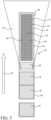
Figure 5 is a schematic cross-sectional illustration of a nuclear fuel rod having an embodiment of an electronics enclosure positioned within the fuel rod, above fuel pellets wherein the electronics enclosure includes a first neutron barrier in the form of powdered reflective and absorbing barrier materials filling those spaces in the cavity that are not occupied by electronic components (not shown) and a second neutron barrier positioned between the electronics cavity and the stack of fuel pellets. - As used herein, the singular form of "a", "an", and "the" include the plural references unless the context clearly dictates otherwise. Thus, the articles "a" and "an" are used herein to refer to one or to more than one (i.e., to at least one) of the grammatical object of the article. By way of example, "an element" means one element or more than one element.
- Directional phrases used herein, such as, for example and without limitation, top, bottom, left, right, lower, upper, front, back, and variations thereof, shall relate to the orientation of the elements shown in the accompanying drawing and are not limiting upon the claims unless otherwise expressly stated.
- In the present application, including the claims, other than where otherwise indicated, all numbers expressing quantities, values or characteristics are to be understood as being modified in all instances by the term "about." Thus, numbers may be read as if preceded by the word "about" even though the term "about" may not expressly appear with the number. Accordingly, unless indicated to the contrary, any numerical parameters set forth in the following description may vary depending on the desired properties one seeks to obtain in the compositions and methods according to the present disclosure. At the very least, and not as an attempt to limit the application of the doctrine of equivalents to the scope of the claims, each numerical parameter described in the present description should at least be construed in light of the number of reported significant digits and by applying ordinary rounding techniques.
- Further, any numerical range recited herein is intended to include all sub-ranges subsumed therein. For example, a range of "1 to 10" is intended to include any and all sub-ranges between (and including) the recited minimum value of 1 and the recited maximum value of 10, that is, having a minimum value equal to or greater than 1 and a maximum value of equal to or less than 10.
- Sensitive electronic components needed in nuclear fuel assemblies may be protected from exposure to neutrons by enclosing the components in an
electronics enclosure 10 equipped with aneutron barrier 20 according to the various embodiments described herein. - Referring to
Figures 1A-1C , an embodiment of theelectronics enclosure 10 includes anenclosure body 14 and alid 12. Aninternal cavity 18 houses non-organic sensors and other electronic components (not shown) critical for various instrumentation and measurement applications. The sensors may include, for example, transmitters, capacitors, and detectors for measuring environmental conditions, such as in-core radioactivity sensors, thermocouple sensors, temperature sensors, pressure sensors and the like. Thecavity 18 may be made into any shape best suited to house the particular non-organic components to be placed in theenclosure 10. - In certain aspects, the
cavity 18, as shown inFigure 1A-1C , may include one or moreseparate compartments 32 of a different size to accommodate different components. Thecompartments 32 may be separated fromcavity 18 by awall 34 or may be continuous.Cavity 18 also includespassages enclosure 10, respectively.Lid 12 may include threadedholes 30 leading intocavity 18 for placement of screws (not shown) to hold the electronics in place within thecavity 18 to prevent movement or shifting of the electronic components. In use, in certain aspects, after the sensor or other electronic components have been inserted in thecavity 18,lid 12 is attached tobody 14 with screws orother fasteners 16. Alternatively,cavity 18 may be one single cavity of uniform or non-uniform dimensions. - In various aspects,
enclosure 10 is made of a ceramic based material. Theenclosure 10 is designed to fit within the inner diameter of anuclear fuel rod 40 and preferably positioned axially near the top of thefuel rod 40 in the upper plenum region, as shown inFigure 5 . - The
electronic enclosure 10 also includes aneutron barrier 20 surrounding the electronic components.Neutron barrier 20 includes a neutron reflecting material and a neutron absorbing material. - When a neutron interacts with the
electronic enclosure 10, theneutron reflecting material 22 will act as the first layer of theneutron barrier 20 to shield the electronic components from neutrons. Beryllium Oxide (BeO), for example, is suitable as the neutron reflecting material because it has very low thermal and fast nuclear absorption cross sections but a relatively high scattering cross section. When neutrons interact with BeO the majority will scatter elastically away from the sensitive electronics. Many neutrons will be reflected back into the moderator. A moderator, as used herein, means the material that surrounds the fuel rod and thermalizes, or slows down, the neutrons. In a pressurized water reactor, for example, the moderator is water. Theneutron absorbing material 24 provides the second layer of theneutron barrier 20 to shield the electronic components from neutrons. Gadolinium (Gd) containing materials are examples of suitable neutron absorbing materials. Gadolinium in the form of gadolinium oxide or gadolinium isotopes Gd-155 and Gd-157 have the highest neutron capture rate of any stable isotope with thermal absorption cross-sections of 61,000 and 254,000 barns respectively. These materials will be very effective at absorbing thermal neutrons and protecting the sensitive electronics. - It is important to note that BeO and Gd2O3 are not required for the neutron reflecting and neutron absorbing materials and are listed as examples only. There are other commercially available ceramics with highly reflective and absorptive properties. Examples of neutron reflecting materials useful in the
neutron barrier 20 include beryllium, beryllium oxides, beryllium nitrides or beryllium carbides. Examples of neutron absorbing materials include gadolinium metals, gadolinium oxides, gadolinium isotopes, ceramic compounds of gadolinium, cadmium metals, cadmium oxides, born metals, boron oxides, hafnium metals, hafnium oxides, etc. The materials are most preferably made of the ceramic forms of the base materials to ensure high temperature operation and also to act as an electrical insulation barrier for the conductive electronics. - As the reflecting and absorbing
layers neutron barrier 20 are irradiated with neutrons over time, the mechanical properties and structure will degrade. The use of asupport structure 26, in certain embodiments as the primary structural support or in certain embodiments as an additional structural support, provides structure forenclosure 10 in the event degradation weakens theneutron barrier 20. Thestructural support 26 may be made of a neutron transparent material that is neither a neutron reflecting nor a neutron absorbing material. In various aspects, the neutron transparent material may be a ceramic material, and may preferably be made of alumina (Al2O3). - Various configurations of
neutron barrier 20 may satisfy the neutron shielding function to protect the electronic components incavity 18. In one aspect, theenclosure body 14 may be formed from astructural support 26 and one or more neutron barrier layers. In this embodiment, theneutron barrier 20 may be formed from a solid neutronreflective layer 22 that surrounds a solidneutron absorbing layer 24. Bothsurround cavity 18. - In one aspect, neutron
reflective layer 22, alone or withneutron absorbing layer 24, may provide the structural support and an additional orseparate support structure 26 may be eliminated.Figure 2 illustrates a configuration for theneutron barrier 20 wherein theneutron reflecting layer 22 and theneutron absorbing layer 24 act both as the structural support and the neutron shield for theelectronic enclosure 10. The solid neutronreflective layer 22 may alone function as the structural support to giveenclosure body 14 its solid structure. In this embodiment,enclosure body 14 comprises the solid neutronreflective layer 22 surrounding the solidneutron absorbing layer 24. In various aspects, the neutron reflecting layer may be made of beryllium or a beryllium containing compound, such as beryllium oxide (BeO). In various aspects, the neutron absorbing layer may be made of gadolinium or a gadolinium containing compound, such as gadolinium oxide (Gd2O3). -
Figure 3 schematically illustrates an alternative embodiment ofenclosure 10 wherein the outermost layer is astructural support 26, made of a neutron transparent material, such as a ceramic material. The ceramic material used forsupport structure 26 may be alumina. The use of alumina is well understood in nuclear applications and will provide either primary structural support or additional structural support forenclosure 10. In the embodiment shown inFigure 3 , thestructural support 26 surrounds a solid neutronreflective layer 22 which in turn surrounds a solidneutron absorbing layer 24, which surroundscavity 18. - In various aspects, the
neutron absorbing material 24 may be in the form of a powder which fills the spaces incavity 18 that remain after the electronics components are inserted into thecavity 18. Aneutron absorbing material 24 in powdered form is packed intocavity 18 and anyother cavities 32 orpassages Figure 4 schematically illustrates a configuration ofenclosure 10 having, for example, an alumina (Al2O3) ceramicstructural support 26 surrounding a solidneutron reflecting layer 22 which surrounds acavity 18 filled with aneutron absorbing material 24 in powder form. Alternatively, the powderedneutron absorbing material 24 may be in the form of pressed powdered layer lining the interior ofcavity 18 surrounding the electronic components. - In another embodiment of the
neutron barrier 20, the reflecting and absorbing layers may both be in powdered form surrounded by a non-reflecting, non-absorbingstructural support 26. For example, both BeO and Gd2O3 are available in powder form. The powders may be in the form of a homogenous mixture or may be in the form of pressed powdered layers, with alternating layers of at least one layer of each of the neutron reflecting and absorbingmaterials Figure 5 illustrates one configuration ofenclosure 10 whereinneutron barrier 20 is in powdered form packed around the sensitive electronics (not shown). - In another embodiment, a solid reflecting
layer 22 comprising a first part ofneutron barrier 20 may act as thesupport structure 26 andsurround cavity 18. The neutron absorbing material comprising a second part of theneutron barrier 20 may be in the form of a powder packed around the electronic components and filling spaces incavity 18 not occupied by the electronic components, such as thewire passages neutron absorbing material 24 may be in the form of pressed powdered layer lining the interior ofcavity 18 surrounding the electronic components. - In an embodiment shown in
Figure 5 , there may be at least two neutron absorbing layers in different positions withinenclosure 10. An initial or forwardneutron absorbing layer 38 is shown. The forwardneutron absorbing layer 38 may provide an initial shield against neutrons coming from thenuclear fuel rod 40. For example, the forwardneutron absorbing layer 38 may be placed below theelectronics cavity 18 between the center of the reactor core and the sensitive electronics. It is understood that neutrons in the plenum region of anuclear fuel rod 40 will come from all directions but will have an upward bias, in the direction shown byarrow 46. In this embodiment,enclosure 10 shields the electronics from neutrons that come from the center of the core that have this upward bias. The placement of the forwardneutron absorbing layer 38 in the path of the neutron flow will cast a "neutron shadow" 44 over the electronics as illustrated inFigure 5 , absorbing neutrons that might otherwise have been directed toward the area of theshadow 44. The forwardneutron absorbing layer 38 may be a block of a solid material, such as a gadolinium containing material or any of the neutron absorbing materials discussed above. As stated above, gadolinium oxide is only one of several materials that may be used in theneutron barrier 20. Gd metal (or another material with a high neutron cross section) may be used as the forwardneutron absorbing layer 38. - A benefit from forward
neutron absorbing layer 38 is that it can be made thicker than the absorbing layer forming part of theenclosure 10 or packed in thecavity 18. Thethicker layer 38 will therefore be able to absorb more neutrons. - In this arrangement, the
neutron barrier 20 can be made from electrically conductive metal, such as cadmium, boron, hafnium, and gadolinium, without shorting any of the electronics because it can be separated from the components. - Various aspects of the subject matter described herein are set out in the following examples.
- Example 1: An enclosure for non-organic electronic components comprising:
- a supporting structure defining an inner cavity for housing non-organic electronic components; and
- a neutron barrier formed from neutron reflecting materials and neutron absorbing materials for shielding electronic components housed in the cavity from neutrons.
- Example 2: The enclosure of example 1 wherein the neutron barrier is comprised of a solid neutron reflecting layer surrounding the neutron absorbing material.
- Example 3: The enclosure of example 2 wherein the solid neutron reflecting layer is the supporting structure.
- Example 4: The enclosure of example 3 wherein the neutron absorbing material comprises a solid inner layer adjacent to and surrounding the cavity.
- Example 5: The enclosure of example 3 wherein the neutron absorbing material comprises a powder filling the cavity and, in use, surrounding the electronic components.
- Example 6: The enclosure of example 2 wherein the supporting structure is a neutron transparent material surrounding the solid neutron reflecting layer.
- Example 7: The enclosure of example 6 wherein the neutron absorbing material comprises a solid inner layer adjacent to and surrounding the cavity.
- Example 8: The enclosure of example 6 wherein the neutron absorbing material comprises a powder filling the cavity and, in use, surrounding the electronic components.
- Example 9: The enclosure of example 1 wherein the supporting structure is a solid neutron transparent material; and the neutron reflecting material and the neutron absorbing material comprise powders contained within the inner cavity.
- Example 10: The enclosure of example 9 wherein the neutron reflecting and neutron absorbing powders form a mixture filling the cavity and, in use, surrounding the electronic components.
- Example 11: The enclosure of example 9 wherein the neutron reflecting powder and the neutron absorbing powder are disposed in layers, the neutron absorbing powder layer disposed adjacent to and surrounding the cavity and the neutron reflecting powder layer disposed between the solid ceramic layer and the neutron absorbing powder layer.
- Example 12: The enclosure of example 9 wherein the neutron reflecting powder and the neutron absorbing powder are disposed in multiple alternating layers.
- Example 13: The enclosure of example 9 wherein the neutron reflecting powder is disposed in a layer adjacent to the solid neutron transparent layer and the neutron absorbing powder fills the cavity and, in use, surrounds the electronic components.
- Example 14: The enclosure of example 9 wherein the supporting structure is formed from alumina.
- Example 15: The enclosure of example 1 wherein the neutron reflecting material comprises beryllium or a beryllium containing ceramic compound.
- Example 16: The enclosure of example 1 wherein the neutron absorbing material comprises gadolinium or a gadolinium containing ceramic compound.
- Example 17: The enclosure of example 1 wherein the neutron absorbing material is selected from the group consisting of gadolinium, cadmium, boron, hafnium, ceramic compounds containing of one or more of gadolinium, cadmium, boron, and hafnium, metal compounds containing gadolinium, and combinations thereof.
- Example 18: The enclosure of example 1 wherein the enclosure has a bottom end and an upper end and further comprising a block of the neutron absorbing material positioned between the bottom end and the cavity.
- Example 19: An enclosure for non-organic electronic components for use in a nuclear fuel rod wherein the fuel rod has a section for containing nuclear fuel comprising:
- an outer structural layer defining an inner cavity for receiving, in use, non-organic electronic components;
- a neutron barrier disposed between the structural layer and the cavity, the neutron barrier comprising at least one neutron reflecting layer and at least one neutron absorbing layer; and
- a forward neutron absorbing layer positioned between the section for containing nuclear fuel and the cavity.
- Example 20: The enclosure of example 19 wherein the outer structural layer comprises an exterior alumina layer.
- Example 21: The enclosure of example 19 wherein the neutron reflecting layer comprises beryllium or a beryllium containing ceramic compound.
- Example 22: The enclosure of example 19 wherein the neutron barrier comprises a mixture of a powdered neutron reflecting material and a powdered neutron absorbing material disposed within the cavity in a sufficient volume to fill the cavity and surround, in use, the electronic components.
- Example 23: The enclosure of example 19 wherein the neutron barrier comprises a layer of a powdered neutron reflecting material and a layer of a powdered neutron absorbing material, wherein the layer of neutron reflecting material is positioned adjacent to and in contact with the structural layer and the layer of the neutron absorbing material is positioned between the neutron reflecting material and the cavity.
- Example 24: The enclosure of example 19 wherein the neutron barrier comprises a layer of a powdered neutron reflecting material positioned adjacent to and in contact with the structural layer and a powdered neutron absorbing material disposed within the cavity in a sufficient volume to fill the cavity and surround, in use, the electronic components.
- Example 25: The enclosure of example 19 wherein the neutron absorbing material of the neutron barrier and the forward neutron absorbing layer are the same or different and each is selected from the group consisting of gadolinium, cadmium, boron, hafnium, ceramic compounds containing of one or more of gadolinium, cadmium, boron, and hafnium, metal compounds containing gadolinium, and combinations thereof.
- The present invention has been described in accordance with several examples, which are intended to be illustrative in all aspects rather than restrictive. Thus, the present invention is capable of many variations in detailed implementation, which may be derived from the description contained herein by a person of ordinary skill in the art.
- The present invention has been described with reference to various exemplary and illustrative embodiments. The embodiments described herein are understood as providing illustrative features of varying detail of various embodiments of the disclosed invention; and therefore, unless otherwise specified, it is to be understood that, to the extent possible, one or more features, elements, components, constituents, ingredients, structures, modules, and/or aspects of the disclosed embodiments may be combined, separated, interchanged, and/or rearranged with or relative to one or more other features, elements, components, constituents, ingredients, structures, modules, and/or aspects of the disclosed embodiments without departing from the scope of the disclosed invention. Accordingly, it will be recognized by persons having ordinary skill in the art that various substitutions, modifications or combinations of any of the exemplary embodiments may be made without departing from the scope of the invention. In addition, persons skilled in the art will recognize, or be able to ascertain using no more than routine experimentation, many equivalents to the various embodiments of the invention described herein upon review of this specification. Thus, the invention is not limited by the description of the various embodiments, but rather by the claims.
Claims (17)
- An enclosure (10) for non-organic electronic components, the enclosure comprising:an outermost supporting structure (26); anda neutron barrier (20) formed from a solid neutron reflecting material (22) and a solid neutron absorbing material (24);wherein the supporting structure (26) and the neutron barrier (20) define an inner cavity (18) for housing non-organic electronic components located within a nuclear reactor core;the neutron barrier (20) is for shielding electronic components housed in the cavity (18) from neutrons and for surrounding electronic components housed in the cavity (18);the supporting structure (26) is solid neutron transparent material; andthe neutron reflecting material (22) and the neutron absorbing material (24) comprise powders contained within the inner cavity (18).
- The enclosure (10) recited in claim 1 wherein the neutron barrier is comprised of a solid neutron reflecting layer surrounding the neutron absorbing material.
- The enclosure (10) recited in claim 2 wherein the solid neutron reflecting layer (22) is the supporting structure.
- The enclosure (10) recited in claim 2 wherein the supporting structure (26) is a neutron transparent material surrounding the solid neutron reflecting layer (22).
- The enclosure (10) recited in either claim 2 or 3 wherein the neutron absorbing material (24) comprises:a solid inner layer adjacent to and surrounding the cavity (18); ora powder filling the cavity (18) and, in use, surrounding the electronic components.
- The enclosure (10) recited in claim 1 wherein the supporting structure (26) is a solid neutron transparent material; and,
the neutron reflecting material (22) and the neutron absorbing material (24) comprise powders contained within the inner cavity (18). - The enclosure (10) recited in claim 6 wherein the neutron reflecting (22) powder and the neutron absorbing (24) powder:form a mixture filling the cavity (18) and, in use, surrounding the electronic components; orare disposed in layers, the neutron absorbing powder layer disposed adjacent to and surrounding the cavity (18) and the neutron reflecting powder layer disposed between the solid ceramic layer and the neutron absorbing powder layer; orare disposed in multiple alternating layers.
- The enclosure (10) recited in claim 6 wherein the neutron reflecting (22) powder is disposed in a layer adjacent to the solid neutron transparent layer and the neutron absorbing (24) powder fills the cavity (18) and in use, surrounds the electronic components.
- The enclosure (10) recited in claim 6 wherein the supporting structure (26) is formed from alumina.
- The enclosure (10) recited in claim 1 wherein the neutron reflecting material (22) comprises beryllium or a beryllium containing ceramic compound.
- The enclosure (10) recited in claim 1 wherein the neutron absorbing material (24):comprises gadolinium or a gadolinium containing ceramic compound; oris selected from the group consisting of gadolinium, cadmium, boron, hafnium, ceramic compounds containing of one or more of gadolinium, cadmium, boron, and hafnium, metal compounds containing gadolinium, and combinations thereof.
- The enclosure (10) recited in claim 1 wherein the enclosure (10) has a bottom end and an upper end and further comprising a block of the neutron absorbing material (24) positioned between the bottom end and the cavity (18).
- An enclosure (10) for non-organic electronic components for use in a nuclear fuel rod (40) wherein the fuel rod (40) has a section for containing nuclear fuel, the enclosure (10) comprising:an outer structural layer (26) defining an inner cavity (18) for receiving, in use, non-organic electronic components;a neutron barrier (20) disposed between the structural layer (26) and the cavity (18), the neutron barrier (20) comprising at least one neutron reflecting layer (22) and at least one neutron absorbing layer (24); and,a forward neutron absorbing layer (38) positioned between the section for containing nuclear fuel and the cavity (18).
- The enclosure (10) recited in claim 13 wherein the outer structural layer (26) comprises an exterior alumina layer.
- The enclosure (10) recited in claim 13 wherein the neutron reflecting layer (22) comprises beryllium or a beryllium containing ceramic compound.
- The enclosure (10) recited in claim 13 wherein the neutron barrier (20) comprises:a mixture of a powdered neutron reflecting material (22) and a powdered neutron absorbing material (24) disposed within the cavity (18) in a sufficient volume to fill the cavity and surround, in use, the electronic components; ora layer of a powdered neutron reflecting material (22) and a layer of a powdered neutron absorbing material (24), wherein the layer of neutron reflecting material (22) is positioned adjacent to and in contact with the structural layer (26) and the layer of the neutron absorbing material (24) is positioned between the neutron reflecting material (22) and the cavity; ora layer of a powdered neutron reflecting material (20) positioned adjacent to and in contact with the structural layer (26) and a powdered neutron absorbing material (24) disposed within the cavity (18) in a sufficient volume to fill the cavity (18) and surround, in use, the electronic components.
- The enclosure (10) recited in claim 13 wherein the neutron absorbing material (24) of the neutron barrier (20) and the forward neutron absorbing layer (38) are the same or different and each is selected from the group consisting of gadolinium, cadmium, boron, hafnium, ceramic compounds containing of one or more of gadolinium, cadmium, boron, and hafnium, metal compounds containing gadolinium, and combinations thereof.
Applications Claiming Priority (3)
| Application Number | Priority Date | Filing Date | Title |
|---|---|---|---|
| US16/210,407 US11424046B2 (en) | 2018-12-05 | 2018-12-05 | Electronic enclosure with neutron shield for nuclear in-core applications |
| EP19893862.3A EP3891763B1 (en) | 2018-12-05 | 2019-11-06 | Electronic enclosure with neutron shield for nuclear in-core applications |
| PCT/US2019/059959 WO2020117415A1 (en) | 2018-12-05 | 2019-11-06 | Electronic enclosure with neutron shield for nuclear in-core applications |
Related Parent Applications (2)
| Application Number | Title | Priority Date | Filing Date |
|---|---|---|---|
| EP19893862.3A Division-Into EP3891763B1 (en) | 2018-12-05 | 2019-11-06 | Electronic enclosure with neutron shield for nuclear in-core applications |
| EP19893862.3A Division EP3891763B1 (en) | 2018-12-05 | 2019-11-06 | Electronic enclosure with neutron shield for nuclear in-core applications |
Publications (2)
| Publication Number | Publication Date |
|---|---|
| EP4510151A2 true EP4510151A2 (en) | 2025-02-19 |
| EP4510151A3 EP4510151A3 (en) | 2025-07-30 |
Family
ID=70970561
Family Applications (2)
| Application Number | Title | Priority Date | Filing Date |
|---|---|---|---|
| EP19893862.3A Active EP3891763B1 (en) | 2018-12-05 | 2019-11-06 | Electronic enclosure with neutron shield for nuclear in-core applications |
| EP24216074.5A Pending EP4510151A3 (en) | 2018-12-05 | 2019-11-06 | Electronic enclosure with neutron shield for nuclear in-core applications |
Family Applications Before (1)
| Application Number | Title | Priority Date | Filing Date |
|---|---|---|---|
| EP19893862.3A Active EP3891763B1 (en) | 2018-12-05 | 2019-11-06 | Electronic enclosure with neutron shield for nuclear in-core applications |
Country Status (6)
| Country | Link |
|---|---|
| US (1) | US11424046B2 (en) |
| EP (2) | EP3891763B1 (en) |
| JP (1) | JP7478736B2 (en) |
| KR (1) | KR20210088728A (en) |
| ES (1) | ES3052963T3 (en) |
| WO (1) | WO2020117415A1 (en) |
Families Citing this family (5)
| Publication number | Priority date | Publication date | Assignee | Title |
|---|---|---|---|---|
| US11424046B2 (en) | 2018-12-05 | 2022-08-23 | Westinghouse Electric Company Llc | Electronic enclosure with neutron shield for nuclear in-core applications |
| WO2021202882A1 (en) | 2020-04-01 | 2021-10-07 | Holtec International | Storage system for radioactive nuclear waste with pressure surge protection |
| CN113481503A (en) * | 2020-11-06 | 2021-10-08 | 江苏清联光电技术研究院有限公司 | Preparation method of boron particle reinforced metal matrix composite material, composite material and application thereof |
| US20220230901A1 (en) * | 2021-01-21 | 2022-07-21 | Micron Technology, Inc. | Containers for protecting semiconductor devices and related methods |
| JP7648765B2 (en) | 2021-07-06 | 2025-03-18 | エルジー エナジー ソリューション リミテッド | Battery cell and battery module including same |
Family Cites Families (17)
| Publication number | Priority date | Publication date | Assignee | Title |
|---|---|---|---|---|
| JPS5341694A (en) * | 1976-09-27 | 1978-04-15 | Toshiba Corp | Fuel assembly for reactor |
| FR2385187A1 (en) * | 1977-03-23 | 1978-10-20 | Electricite De France | LOCAL POWER MEASUREMENT DEVICE IN A NUCLEAR REACTOR FUEL ASSEMBLY |
| US4639349A (en) | 1982-03-22 | 1987-01-27 | Research Corporation | Non-invasive liquid level and density gauge for nuclear power reactor pressure vessels |
| JP2004212372A (en) | 2003-01-07 | 2004-07-29 | Toshihisa Shirakawa | Fuel assembly of nuclear reactor |
| JP4354250B2 (en) * | 2003-10-16 | 2009-10-28 | 能美防災株式会社 | Protection equipment for disaster prevention equipment |
| US20110024613A1 (en) * | 2009-06-29 | 2011-02-03 | Baker Hughes Incorporated | Materials for use as structural neutron moderators in well logging tools |
| GB0915474D0 (en) | 2009-09-04 | 2009-10-07 | Micromass Ltd | Multiple reaction monitoring with a time-of-flight based mass spectrometer |
| JP2011080886A (en) | 2009-10-08 | 2011-04-21 | Toshiba Corp | Reflector control type fast reactor, and reflector used for the same |
| EP2355108B1 (en) | 2010-02-08 | 2012-11-14 | Technische Universität München | Shielding material and shielding element for shielding gamma and neutron radiation |
| US20120281803A1 (en) * | 2011-05-07 | 2012-11-08 | Gip International, Ltd | Neutron absorbing composite for nuclear reactor applications |
| CA2860823A1 (en) * | 2011-12-20 | 2013-06-27 | Nihon Nature Cell Co., Ltd. | Compact nuclear power generation system |
| US9261624B2 (en) * | 2013-06-14 | 2016-02-16 | Baker Hughes Incorporated | Thermal and epithermal neutrons from an earth formation |
| US9151722B2 (en) * | 2014-01-15 | 2015-10-06 | King Abdulaziz University | Systems for determining and imaging wax deposition and simultaneous corrosion and wax deposit determination in pipelines |
| GB2526109A (en) * | 2014-05-14 | 2015-11-18 | Symetrica Ltd | Neutron detection |
| FR3030860B1 (en) | 2014-12-19 | 2016-12-30 | Commissariat Energie Atomique | COMBUSTIBLE ASSEMBLY FOR RNR-NA TYPE NUCLEAR REACTOR, HAVING A REMOVABLE SOLIDARIZED NEUTRONIC PROTECTION DEVICE |
| EP3806110A1 (en) * | 2015-12-15 | 2021-04-14 | Clear Inc. | Nuclear reactor system for extinguishing radioactivity |
| US11424046B2 (en) | 2018-12-05 | 2022-08-23 | Westinghouse Electric Company Llc | Electronic enclosure with neutron shield for nuclear in-core applications |
-
2018
- 2018-12-05 US US16/210,407 patent/US11424046B2/en active Active
-
2019
- 2019-11-06 EP EP19893862.3A patent/EP3891763B1/en active Active
- 2019-11-06 KR KR1020217020437A patent/KR20210088728A/en not_active Ceased
- 2019-11-06 ES ES19893862T patent/ES3052963T3/en active Active
- 2019-11-06 WO PCT/US2019/059959 patent/WO2020117415A1/en not_active Ceased
- 2019-11-06 JP JP2021532123A patent/JP7478736B2/en active Active
- 2019-11-06 EP EP24216074.5A patent/EP4510151A3/en active Pending
Also Published As
| Publication number | Publication date |
|---|---|
| JP2022511530A (en) | 2022-01-31 |
| WO2020117415A1 (en) | 2020-06-11 |
| EP3891763B1 (en) | 2025-09-10 |
| EP3891763A4 (en) | 2022-08-03 |
| EP4510151A3 (en) | 2025-07-30 |
| US11424046B2 (en) | 2022-08-23 |
| EP3891763A1 (en) | 2021-10-13 |
| KR20210088728A (en) | 2021-07-14 |
| ES3052963T3 (en) | 2026-01-16 |
| US20200185116A1 (en) | 2020-06-11 |
| JP7478736B2 (en) | 2024-05-07 |
Similar Documents
| Publication | Publication Date | Title |
|---|---|---|
| EP3891763B1 (en) | Electronic enclosure with neutron shield for nuclear in-core applications | |
| US20060291606A1 (en) | Micro neutron detectors | |
| KR101752524B1 (en) | Primary neutron source multiplier assembly | |
| EP3036745B1 (en) | Ion chamber radiation detector | |
| KR102398911B1 (en) | Systems and methods for performing active scanning of nuclear fuel rods | |
| KR101376704B1 (en) | In-Core Instrument Assembly for Improvement of neutron flux detection sensitivity | |
| US4090083A (en) | Nuclear reactor ex-core startup neutron detector | |
| KR20170105018A (en) | Working neutron source | |
| EP3990948A1 (en) | A neutron detector with solid-liquid moderators for measuring neutrons at different energy ranges | |
| EP0338772B1 (en) | Nuclear reactor control rod with encapsulated neutron absorbent | |
| KR20210102464A (en) | Temperature sensor using a material with a temperature-dependent neutron capture cross-section | |
| Böck | Miniature detectors for reactor incore neutron flux monitoring | |
| RU2179751C1 (en) | Fuel element | |
| JPH0458193A (en) | Neutron absorbing element for reactor control rod | |
| Hashemi-Tilehnoee et al. | Improving the performance of the power monitoring channel | |
| Senftle et al. | Construction materials for neutron capture-gamma-ray measurement assembly using Californium-252 | |
| RU2331942C1 (en) | In-vessel radiation shield unit | |
| Roux | Parallel-Plate Multisection Ionization Chambers for High-Performance Reactors | |
| Cook | SEC-00256 Pinellas Plant Technical Overview | |
| Jassby et al. | The TFTR lithium blanket module program | |
| Rhodes et al. | Intensity of unscattered gamma rays inside cylindrical self-absorbing sources | |
| Rokrok et al. | Investigation of required modifications of the manufactured TRR DPC for transport and storage of two-year cooled spent fuel assemblies | |
| Williams et al. | Benchmark experiments for space Reactor neutron shielding of mission electronics | |
| Dosimbaev et al. | Water and air activity during the operation of the WWR-SM reactor with the fuel enriched in 235U to 36% | |
| Wood et al. | A Filter for Fast Flux Testing in a Thermal Test Reactor |
Legal Events
| Date | Code | Title | Description |
|---|---|---|---|
| PUAI | Public reference made under article 153(3) epc to a published international application that has entered the european phase |
Free format text: ORIGINAL CODE: 0009012 |
|
| STAA | Information on the status of an ep patent application or granted ep patent |
Free format text: STATUS: THE APPLICATION HAS BEEN PUBLISHED |
|
| AC | Divisional application: reference to earlier application |
Ref document number: 3891763 Country of ref document: EP Kind code of ref document: P |
|
| AK | Designated contracting states |
Kind code of ref document: A2 Designated state(s): AL AT BE BG CH CY CZ DE DK EE ES FI FR GB GR HR HU IE IS IT LI LT LU LV MC MK MT NL NO PL PT RO RS SE SI SK SM TR |
|
| REG | Reference to a national code |
Ref country code: DE Ref legal event code: R079 Free format text: PREVIOUS MAIN CLASS: G21F0003000000 Ipc: G21C0003160000 |
|
| RIC1 | Information provided on ipc code assigned before grant |
Ipc: G21F 3/00 20060101ALI20250401BHEP Ipc: G21F 1/12 20060101ALI20250401BHEP Ipc: G21C 17/10 20060101ALI20250401BHEP Ipc: G21C 3/16 20060101AFI20250401BHEP |
|
| PUAL | Search report despatched |
Free format text: ORIGINAL CODE: 0009013 |
|
| AK | Designated contracting states |
Kind code of ref document: A3 Designated state(s): AL AT BE BG CH CY CZ DE DK EE ES FI FR GB GR HR HU IE IS IT LI LT LU LV MC MK MT NL NO PL PT RO RS SE SI SK SM TR |
|
| RIC1 | Information provided on ipc code assigned before grant |
Ipc: G21C 3/16 20060101AFI20250625BHEP Ipc: G21C 17/10 20060101ALI20250625BHEP Ipc: G21F 1/12 20060101ALI20250625BHEP Ipc: G21F 3/00 20060101ALI20250625BHEP |
|
| STAA | Information on the status of an ep patent application or granted ep patent |
Free format text: STATUS: REQUEST FOR EXAMINATION WAS MADE |
|
| 17P | Request for examination filed |
Effective date: 20260127 |