EP4509943A1 - Control knob - Google Patents
Control knob Download PDFInfo
- Publication number
- EP4509943A1 EP4509943A1 EP23192167.7A EP23192167A EP4509943A1 EP 4509943 A1 EP4509943 A1 EP 4509943A1 EP 23192167 A EP23192167 A EP 23192167A EP 4509943 A1 EP4509943 A1 EP 4509943A1
- Authority
- EP
- European Patent Office
- Prior art keywords
- knob
- encoder
- assembly
- shaft
- bearing collar
- Prior art date
- Legal status (The legal status is an assumption and is not a legal conclusion. Google has not performed a legal analysis and makes no representation as to the accuracy of the status listed.)
- Pending
Links
Images



Classifications
-
- G—PHYSICS
- G05—CONTROLLING; REGULATING
- G05G—CONTROL DEVICES OR SYSTEMS INSOFAR AS CHARACTERISED BY MECHANICAL FEATURES ONLY
- G05G1/00—Controlling members, e.g. knobs or handles; Assemblies or arrangements thereof; Indicating position of controlling members
- G05G1/08—Controlling members for hand actuation by rotary movement, e.g. hand wheels
- G05G1/10—Details, e.g. of discs, knobs, wheels or handles
-
- G—PHYSICS
- G05—CONTROLLING; REGULATING
- G05G—CONTROL DEVICES OR SYSTEMS INSOFAR AS CHARACTERISED BY MECHANICAL FEATURES ONLY
- G05G1/00—Controlling members, e.g. knobs or handles; Assemblies or arrangements thereof; Indicating position of controlling members
- G05G1/02—Controlling members for hand actuation by linear movement, e.g. push buttons
-
- G—PHYSICS
- G05—CONTROLLING; REGULATING
- G05G—CONTROL DEVICES OR SYSTEMS INSOFAR AS CHARACTERISED BY MECHANICAL FEATURES ONLY
- G05G1/00—Controlling members, e.g. knobs or handles; Assemblies or arrangements thereof; Indicating position of controlling members
- G05G1/08—Controlling members for hand actuation by rotary movement, e.g. hand wheels
- G05G1/10—Details, e.g. of discs, knobs, wheels or handles
- G05G1/12—Means for securing the members on rotatable spindles or the like
-
- G—PHYSICS
- G05—CONTROLLING; REGULATING
- G05G—CONTROL DEVICES OR SYSTEMS INSOFAR AS CHARACTERISED BY MECHANICAL FEATURES ONLY
- G05G23/00—Means for ensuring the correct positioning of parts of control mechanisms, e.g. for taking-up play
-
- H—ELECTRICITY
- H01—ELECTRIC ELEMENTS
- H01H—ELECTRIC SWITCHES; RELAYS; SELECTORS; EMERGENCY PROTECTIVE DEVICES
- H01H25/00—Switches with compound movement of handle or other operating part
- H01H25/06—Operating part movable both angularly and rectilinearly, the rectilinear movement being along the axis of angular movement
-
- H—ELECTRICITY
- H01—ELECTRIC ELEMENTS
- H01H—ELECTRIC SWITCHES; RELAYS; SELECTORS; EMERGENCY PROTECTIVE DEVICES
- H01H3/00—Mechanisms for operating contacts
- H01H3/02—Operating parts, i.e. for operating driving mechanism by a mechanical force external to the switch
- H01H3/08—Turn knobs
- H01H3/10—Means for securing to shaft of driving mechanism
Definitions
- the disclosure relates to a control knob, in particular to a control knob that allows rotary motion as well as linear motion.
- Control knobs are used for many different applications. In media devices, for example, control knobs may be used for regulating or adjusting different parameters such as, e.g., a volume of sound that is output by the media device.
- a control knob is a rotary device that can be used to provide manual input adjustments to a mechanical or electrical system when grasped and turned by a human operator. Differing extend of knob rotation usually corresponds to different desired input.
- Control knobs are a simple type of input hardware and are very common in different kinds of control systems. Common control knobs work by turning a shaft which connects to a component (e.g., encoder) which produces the actual input.
- a control knob includes an encoder assembly configured to convert rotary and axial input movement into electronic signals, and a knob assembly attached to the encoder assembly and configured to be operated by a user, wherein the encoder assembly includes a shaft encoder having a shaft that is configured to be rotated around a rotation axis and to be moved axially along the rotation axis, the knob assembly comprises an outer knob element configured to be operated by a user, the knob assembly further includes a bush defining a cylindrical cavity inside the outer knob element, wherein the bush has an opening towards a first side of the outer knob element facing towards the encoder assembly, the knob assembly further includes a driver element extending into the bush from a second side opposite the first side, and enclosing the shaft of the shaft encoder to transfer a movement of the outer knob element to the shaft encoder, the encoder assembly further comprises a bearing collar, the bearing collar defining an inner volume that is open towards a first side and towards a second side opposite the first side, wherein the shaft encoder from the first side extends into the inner
- FIG. 1 schematically illustrates a cross-sectional view of a control knob 100 according to embodiments of the disclosure.
- the control knob 100 comprises an encoder assembly 200 configured to convert rotary and axial input movement into electronic signals, and a knob assembly 300 attached to the encoder assembly 200 and configured to be operated by a user.
- the knob assembly 300 generally is the visible part of the control knob 100 and covers the encoder assembly 200.
- the encoder assembly 200 comprises a shaft encoder 202 configured to be rotated around a rotation axis A1 and to be moved axially along the rotation axis A1.
- Shaft encoders 202 are generally known and are often also referred to as rotary encoders.
- a shaft encoder 202 is a device that is able to detect a rotational angle of its shaft, e.g., with respect to a base element. Shaft encoders are often used for control knobs. Generally absolute shaft encoders as well as incremental encoders are known. While absolute shaft encoders can determine a current position of its shaft from the moment the shaft encoder is powered up, incremental encoders can immediately detect changes in position, but are generally not able to track absolute shaft positions.
- An absolute shaft encoder may use mechanical, magnetic or optical sensors with a rotating disc to determine the shaft position, for example.
- Mechanical encoders use sliding contacts and a disc with metal patterns designed to encode the shaft position.
- Magnetic encoders sense the position of magnetized strips on a disc while optical disc encoders read specially-coded light and dark areas.
- the position data from an absolute shaft encoder is outputted in either digital or analog form, usually depending upon the design of the device. Digital data may be represented in binary, gray code, or binary coded decimal, for example.
- Incremental shaft encoders often also known as quadrature encoders, measure relative shaft movement. This type of shaft encoder usually uses only two optical or mechanical sensors from one angle to the next.
- external circuitry can be used to count shaft movements from a reference point.
- mechanical encoders for example, cams on the shaft make contact with mechanical sensors to indicate the shaft position.
- Optical encoders can determine movement by reading light and dark coded tracks, e.g., by means of photodiodes.
- the shaft encoder 202 included in the control knob 100 as described herein can be implemented in any suitable way and is not restricted to any specific implementation
- the knob assembly 300 comprises an outer knob element 302 configured to be operated by a user.
- the knob assembly 300 generally is the part which is contacted by a user's hand.
- the knob assembly 300 further comprises a bush 306 defining a cylindrical cavity inside the outer knob element 302, wherein the bush 306 has an opening towards a first side of the outer knob element 302 facing towards the encoder assembly 200.
- the first side of the outer knob element 302 is generally not visible for a user, as it faces towards the encoder assembly 200.
- the knob assembly 300 further comprises a driver element 304 extending into the bush 306 from a second side of the bush 306 opposite the first side.
- the driver element 304 when the control knob is fully assembled, encloses a shaft of the shaft encoder 202 to transfer a movement of the outer knob element 302 to the shaft encoder 202.
- the shaft of the shaft encoder 202 generally is comparably small and it would be inconvenient for a user to rotate it without the knob assembly 300.
- the knob assembly 300 provides a convenient interface for the user, as the outer knob element 302 generally is significantly larger as compared to the shaft of the shaft encoder 202. Even further, the outer knob element 302 is much more aesthetic than the shaft encoder 202.
- the bush 306 and the driver element 304 are securely attached to the outer knob element 302 in any suitable way such that they rotate together with the outer knob element 302. As the driver element 304 tightly encloses the shaft of the shaft encoder 202, the movement of the outer knob element 302 is reliably transferred to the shaft encoder 202.
- the encoder assembly 200 further comprises a bearing collar 206, the bearing collar 206 defining an inner volume that is open towards a first side and towards a second side opposite the first side.
- the second side of the bearing collar 206 is a side facing towards the knob assembly 300.
- the shaft encoder 202 from the first side extends into the inner volume of the bearing collar 206 towards the second side.
- the driver element 304 extends into the inner volume of the bearing collar 206 from the second side towards the first side, and between the shaft of the shaft encoder 202 and the bearing collar 206. That is, when the control knob 100 is fully assembled, the bearing collar 206 extends around at least a part of the shaft encoder 202 as well as around at least a part of the driver element 304.
- Figure 1 schematically illustrates a partly assembled control knob 100.
- the encoder assembly 200 is fully assembled, with the bearing collar 206 arranged to surround at least the shaft of the shaft encoder 202, and the knob assembly 300 is fully assembled, with the driver element 304 extending into the bush 306.
- the knob assembly 300 and the encoder assembly 200 have not yet been put together in the cross-sectional view of Figure 1 .
- the driver element 304 which is firmly attached to the shaft encoder 202 transfers the movement of the outer knob element 302 to the shaft encoder 202.
- the bush 306 may have a smooth inner surface facing towards the cylindrical cavity, and the bearing collar 206 may have a smooth outer surface facing away from the shaft encoder 202 arranged inside the inner volume defined by the bearing collar 206.
- an inner diameter r306 of the bush 306 may correspond to or may be marginally larger than an outer diameter r206 of the bearing collar 306.
- the inner diameter r306 of the bush 306 may be up to 0.1mm, up to 0.25mm, or up to 0.5mm (millimetres) larger than the outer diameter r206 of the bearing collar 206.
- the outer knob element 302 when the outer knob element 302 is operated by a user, the inner surface of the bush 306 smoothly glides along the outer surface of the bearing collar 206. That is, the bearing collar 206 provides a smooth surface for the bush 306 to run on. This highly improves the handling of the control knob 100.
- the control knob 100 as illustrated in Figure 1 is highly accurate, as the movement of the outer knob element 302 is directly transferred to the shaft encoder 202 by means of the driver element 304.
- the knob assembly 300 may be smoothly operated by a user and provides a highly increased user experience.
- the effects as mentioned above may be achieved by means of comparably cheap elements, resulting in a very low-cost, high precision control knob arrangement. Any unintentional wobbling of the knob assembly 300 during its use is avoided by means of the bush 306 gliding along the surface of the bearing collar 206, as the knob assembly 300 is always maintained concentric with respect to the shaft encoder 202.
- the encoder assembly 200 is illustrated in further detail in Figures 2-5 , wherein Figure 2 schematically illustrates a partly exploded view of an encoder assembly of a control knob 100 according to embodiments of the disclosure, Figure 3 schematically illustrates a three-dimensional view of the encoder assembly 200 of Figure 2 in its assembled state, Figure 4 schematically illustrates a front view of the encoder assembly 200 of Figure 2 in its assembled state, and Figure 5 schematically illustrates a cross-sectional view of the encoder assembly 200 of Figure 2 . From these Figures, the arrangement of the bearing collar 206 with respect to the shaft encoder 202 is clearly visible. The outer periphery of the bearing collar 206 is cylindrical, similar to the inner surface of the bush 306, in order to provide a surface for the bush 306 to run on.
- the internal volume defined by the bearing collar 206 may be at least partly cylindrical.
- a first section of the bearing collar 206 which surrounds the shaft of the shaft encoder 202 which is contacted by the driver element 304 may be cylindrical.
- An inner diameter or radius of this first section may be larger than an outer diameter or radius of the shaft of the shaft encoder 202, and larger than an outer diameter or radius of the driver element 304. In this way, there is sufficient space between the shaft and the bearing collar 206 in order to allow the driver element 304 to firmly engage with the shaft.
- a second section of the bearing collar 206 may define an inner volume that is not cylindrical.
- the first section and the second section of the inner volume as defined by the bearing collar are separated by means of a dashed line in Figure 5 .
- a shape of the inner volume defined by the second section may at least partly correspond to a shape of the shaft encoder 202 (e.g., a shape of the base element).
- the bearing collar 206 may be securely attached to the shaft encoder 202, while still allowing the driver element 304 to engage with the shaft.
- the bearing collar 206 may be attached to the base element of the shaft encoder 202 such that it also remains stationary when the outer knob element 302 is rotated.
- the second section of the bearing collar 206 may comprise a thread
- the base element of the shaft encoder 202 may comprise a counter thread such that the bearing collar 206 may be screwed onto the shaft encoder 202.
- the bearing collar 202 may also be attached to a fascia panel 204.
- a fascia panel 204 is optional and will be described in further detail below.
- the shape of the inner volume of the bearing collar 206 is generally of lower importance, as the bearing collar is mainly configured to provide a surface and rigid fixture for the bush 306 to run on.
- the shaft encoder 202 may be coupled to a plate or fascia panel 204, as is schematically illustrated in Figures 2-5 .
- the shaft encoder 202 comprises the shaft and may further comprise a base element, wherein the shaft of the shaft encoder 202 is movable with respect to the base element.
- the fascia panel 204 may have a first main surface and a second main surface opposite the first main surface, and a hole extending through the fascia panel 204 from the first to the second main surface.
- the shaft encoder 202 may extend through the hole in the fascia panel 204 such that the base element is at least partly arranged on a first side of the fascia panel 204, and the shaft of the shaft element 202 is arranged on a second side of the fascia panel 204.
- the fascia panel 204 can be considered carrying the shaft encoder 202.
- the base element may partly extend through the hole in the fascia panel 204.
- An interface between the base element and the shaft is indicated by means of a dashed line in Figure 5 .
- the fascia panel 204 does not rotate together with the shaft but remains stationary, just as the base element remains stationary.
- the fascia panel 204 has a circular shape. This, however, is only an example.
- the fascia panel 204 may have any other suitable shape instead.
- FIG. 6 schematically illustrates a partly exploded view of a knob assembly 300 of a control knob 100 according to embodiments of the disclosure.
- the knob assembly 300 is illustrated as seen from a back side in Figure 6 , that is, from a side which faces towards the encoder assembly 200.
- the outer knob element 302 is visible as well as the driver element 304 arranged inside a volume defined by the outer knob element 302.
- the bush 306 in this view has not yet been inserted into the outer knob element 302.
- the bush 306 may be a very simple component having an inner diameter d1 and an outer diameter d2.
- the inner volume defined by the bush 306 is cylindrical in order to be able to smoothly run along the outer surface of the bearing collar 206 which is also cylindrical.
- the bush 306 may be retained in the outer knob element 302 by means of a precision interference fit, for example.
- An interference fit often also referred to as pressed fit or friction fit, generally is a form of fastening between two tightfitting mating parts that produces a joint which is held together by friction after the respective parts have been pushed together.
- the bush 306 may be attached to the outer knob element 302 in any other suitable way, or may even be integrally formed with the outer knob element 302.
- the bush 306 provides an interface between the movable outer knob element 302 and the fixed encoder assembly 200.
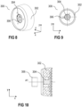
- Figure 8 schematically illustrates a three-dimensional view of the knob assembly of Figure 6 in its assembled state
- Figure 9 schematically illustrates a back view of the knob assembly of Figure 6 in its assembled state. That is, the knob assembly 300 as illustrated in Figures 8 and 9 is ready to be pushed onto the encoder assembly 200 as illustrated in Figures 3 and 4 , for example.
- Figures 8 and 9 illustrate the knob assembly 300 from a back side, that is from a side which, in the fully assembled state, faces towards the encoder assembly 200 and is therefore generally not visible for a user.
- Figure 10 schematically illustrates a cross-sectional view of the knob assembly of Figure 6 , wherein the bush 306 has not yet been mated with the outer knob element 302.
- the driver element 304 may be integrally formed with the outer knob element 302.
- the knob assembly 300 alternatively may further comprise a panel element 308 arranged to cover the second side of the bush 306, wherein the second side of the bush 306 is a side facing away from the encoder assembly 200 in the fully assembled state.
- the driver element 304 may extend from the panel element 308 and into the bush 306.
- the panel element 308 may be attached to the outer knob element 302 by means of one or more screws 310, for example.
- the driver element 304 and the panel element 308 are formed monolithically as a single piece.
- the driver element 304 be attached to a panel element 308 in any other suitable way, e.g., by means of gluing, screwing, etc.
- the knob assembly 300 may further comprise a cover 312 arranged to conceal the panel element 308 and/or any other components arranged inside the outer knob element 302.
- Figure 12 an exploded cross-sectional view of a control knob according to further embodiments of the disclosure is schematically illustrated.
- Figure 13 schematically illustrates a three-dimensional exploded cross-sectional view of the control knob 100 of Figure 12 .
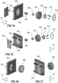
- Figure 14 schematically illustrates an exploded three-dimensional view of a control knob according to further embodiments of the disclosure
- Figure 15 schematically illustrates the exploded three-dimensional view of the control knob of Figure 14 from a different perspective.
- Figure 16 schematically illustrates the control knob of Figure 14 in a partly assembled state from a first perspective (front side)
- Figure 17 schematically illustrates the control knob of Figure 15 in a partly assembled state. That is, Figure 17 schematically illustrates the partly assembled control knob 100 of Figure 16 from a different perspective (back side).
- the control knob 100 may further comprise a circuit board 208, wherein the base element of the shaft encoder 202 is coupled to the circuit board 208.
- the circuit board 208 may carry electrical circuitry and components which are required to convert rotary and axial input movement of the knob assembly 300 into electronic signals, for example.
- Figures 14 to 17 further schematically illustrate a panel or aperture 400.
- the panel or aperture 400 may carry the fascia panel 204 and may conceal the components of the encoder assembly 200.
- the panel or aperture 400 may be part of a casing of a media device, for example.
- the control knob 100 is configured to convert rotary input movement into electronic signals.
- the control knob 100 may also be configured to convert axial input movement into electronic signals.
- the shaft encoder 202 may comprise a push switch (not specifically illustrated). The push switch may close when the knob assembly 300 moves axially along the rotation axis A1 towards the encoder assembly 200, and may open when, subsequently, the knob assembly 300 moves axially along the rotation axis A1 away from the encoder assembly 200. Encoder switches 202 providing such a function are generally known.
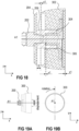
- Figure 18 schematically illustrates an axial movement of the knob assembly 300.
- the knob assembly 300 is illustrated in its normal position (e.g., push switch open).
- the knob assembly 300 is illustrated in a pushed-in position (e.g., push switch closed). That is, a user may push the outer knob element 302 towards the encoder assembly 200. All parts that are firmly attached to the outer knob element 302 such as, e.g., the bush 304, and the driver element 304, are pushed towards the encoder assembly 200 together with the outer knob element 302.
- the outer knob element 302 may be slightly displaced out of its normal position (e.g., x1 ⁇ 3mm, or x1 ⁇ 1mm, dependent on the operation of the particular encoder used) and may then return to its normal position.
- the shaft of the shaft encoder 202 As the shaft of the shaft encoder 202 is tightly connected to the driver element 304, the shaft will also axially move together with the outer knob element 302.
- the shaft may not only be rotationally but also axially movable with respect to the base element. That is, the shaft may be moved in a direction towards the base element.
- the push switch may be located in the base element and may be activated (e.g., closed), when the shaft moves towards the base element along the rotation axis A1.
- the control knob may allow for an axial displacement of the knob assembly 300 with respect to the encoder assembly 200.
- a distance l3 between the outer knob element 302 and a fascia panel 204 may be larger than or at least equal to a maximum displacement x1 of the knob assembly 300 towards the fascia panel 204.
- the inner volume defined by the bearing collar 206 may be large enough to allow for an axial movement of the driver element 304.
- the bearing collar 206 at an interface between the first section and the second section (see Figure 5 ), may provide an end stop for the driver element 304 in order to limit the axial displacement of the knob assembly 300.
- Figure 19A schematically illustrates a side view of an exemplary control knob to visualize an axial displacement of the knob assembly 300 with respect to the encoder assembly 200.
- Figure 19B schematically illustrates a front view of an exemplary control knob to visualize a rotational movement of the knob assembly 300 around the rotation axis A1.
- the knob assembly 300 of a control knob 100 as described above is rigidly supported on the encoder assembly. This results in a high quality feel for a user when operating the knob assembly 300, i.e. the outer knob element 302.
- the shaft encoder 202 may be operated consistently and evenly by means of the arrangements as have been described above. That is, the knob assembly 300 may be smoothly moved.
- Rotary and axial movement of the outer knob element 302 operates the shaft encoder 202 consistently and evenly.
- the arrangements disclosed herein allow for only minimal play or minimal clearance between the knob assembly 300 and the encoder assembly 200, in particular between the bush 306 and the bearing collar 206, due to the close fit of the knob assembly 300 on the bearing collar 206 which eliminates a feeling of "looseness". This reduces the slack or play.
- the knob assembly 300 is rigidly supported on the encoder assembly 200 to eliminate any "wobble" which results in a high quality feel for a user of the control knob 100.
Landscapes
- Physics & Mathematics (AREA)
- General Physics & Mathematics (AREA)
- Engineering & Computer Science (AREA)
- Automation & Control Theory (AREA)
- Rotary Switch, Piano Key Switch, And Lever Switch (AREA)
- Mechanical Control Devices (AREA)
Abstract
A control knob (100) comprises an encoder assembly (200) configured to convert rotary and axial input movement into electronic signals, and a knob assembly (300) attached to the encoder assembly (200) and configured to be operated by a user, wherein the encoder assembly (200) comprises a shaft encoder (202) having a shaft that is configured to be rotated around a rotation axis (A1) and to be moved axially along the rotation axis (A1), the knob assembly (300) comprises an outer knob element (302) configured to be operated by a user, the knob assembly (300) further comprises a bush (306) defining a cylindrical cavity inside the outer knob element (302), wherein the bush (306) has an opening towards a first side of the outer knob element (302) facing towards the encoder assembly (200), the knob assembly (300) further comprises a driver element (304) extending into the bush (306) from a second side opposite the first side, and enclosing the shaft of the shaft encoder (202) to transfer a movement of the outer knob element (302) to the shaft encoder (202), the encoder assembly (200) further comprises a bearing collar (206), the bearing collar (206) defining an inner volume that is open towards a first side and towards a second side opposite the first side, wherein the shaft encoder (202) from the first side extends into the inner volume of the bearing collar (206) towards the second side, the driver element (304) extends into the inner volume of the bearing collar (206) from the second side towards the first side, and between the shaft of the shaft encoder (202) and the bearing collar (206).
Description
- The disclosure relates to a control knob, in particular to a control knob that allows rotary motion as well as linear motion.
- Control knobs are used for many different applications. In media devices, for example, control knobs may be used for regulating or adjusting different parameters such as, e.g., a volume of sound that is output by the media device. Generally speaking, a control knob is a rotary device that can be used to provide manual input adjustments to a mechanical or electrical system when grasped and turned by a human operator. Differing extend of knob rotation usually corresponds to different desired input. Control knobs are a simple type of input hardware and are very common in different kinds of control systems. Common control knobs work by turning a shaft which connects to a component (e.g., encoder) which produces the actual input.
- There is a need for a control knob which, in addition to rotary motion, is able to allow linear motion, which has a high quality feel and may be operated smoothly with minimal play, maximum rigidity for its support, and with high precision, and which may be manufactured at low cost.
- A control knob includes an encoder assembly configured to convert rotary and axial input movement into electronic signals, and a knob assembly attached to the encoder assembly and configured to be operated by a user, wherein the encoder assembly includes a shaft encoder having a shaft that is configured to be rotated around a rotation axis and to be moved axially along the rotation axis, the knob assembly comprises an outer knob element configured to be operated by a user, the knob assembly further includes a bush defining a cylindrical cavity inside the outer knob element, wherein the bush has an opening towards a first side of the outer knob element facing towards the encoder assembly, the knob assembly further includes a driver element extending into the bush from a second side opposite the first side, and enclosing the shaft of the shaft encoder to transfer a movement of the outer knob element to the shaft encoder, the encoder assembly further comprises a bearing collar, the bearing collar defining an inner volume that is open towards a first side and towards a second side opposite the first side, wherein the shaft encoder from the first side extends into the inner volume of the bearing collar towards the second side, the driver element extends into the inner volume of the bearing collar from the second side towards the first side, and between the shaft of the shaft encoder and the bearing collar.
- Other systems, features and advantages of the disclosure will be or will become apparent to one with skill in the art upon examination of the following detailed description and figures. It is intended that all such additional systems, methods, features and advantages included within this description, be within the scope of the invention and be protected by the following claims.
- The arrangements may be better understood with reference to the following description and drawings. The components in the figures are not necessarily to scale, emphasis instead being placed upon illustrating the principles of the invention. Moreover, in the figures, like referenced numerals designate corresponding parts throughout the different views.
-
Figure 1 schematically illustrates a cross-sectional view of a control knob comprising an encoder assembly and a knob assembly. -
Figure 2 schematically illustrates an exploded view of a encoder assembly of a control knob according to embodiments of the disclosure. -
Figure 3 schematically illustrates a three-dimensional view of the encoder assembly ofFigure 2 in its assembled state. -
Figure 4 schematically illustrates a front view of the encoder assembly ofFigure 2 in its assembled state. -
Figure 5 schematically illustrates a cross-sectional view of the encoder assembly ofFigure 2 . -
Figure 6 schematically illustrates an exploded view of a knob assembly of a control knob according to embodiments of the disclosure. -
Figure 7 schematically illustrates a three-dimensional view and a cross-sectional view of a bush of the knob assembly ofFigure 6 . -
Figure 8 schematically illustrates a three-dimensional view of the knob assembly ofFigure 6 in its assembled state. -
Figure 9 schematically illustrates a back view of the knob assembly ofFigure 6 in its assembled state. -
Figure 10 schematically illustrates a cross-sectional view of the knob assembly ofFigure 6 . -
Figure 11 schematically illustrates an exploded three-dimensional view of a knob assembly of a control knob according to further embodiments of the disclosure. -
Figure 12 schematically illustrates an exploded cross-sectional view of a control knob according to further embodiments of the disclosure. -
Figure 13 schematically illustrates a three-dimensional exploded cross-sectional view of the control knob ofFigure 12 . -
Figure 14 schematically illustrates an exploded three-dimensional view of a control knob according to further embodiments of the disclosure. -
Figure 15 schematically illustrates the exploded three-dimensional view of the control knob ofFigure 14 from a different perspective. -
Figure 16 schematically illustrates the control knob ofFigure 14 in a partly assembled state. -
Figure 17 schematically illustrates the control knob ofFigure 15 in a partly assembled state. -
Figure 18 schematically illustrates an axial movement of the knob assembly. -
Figure 19 , includingFigures 19A and 19B , schematically illustrates a side view (Figure 19A ) and a front view (Figure 19B ) of a control knob according to embodiments of the disclosure in its assembled state. -
Figure 1 schematically illustrates a cross-sectional view of acontrol knob 100 according to embodiments of the disclosure. Thecontrol knob 100 comprises anencoder assembly 200 configured to convert rotary and axial input movement into electronic signals, and aknob assembly 300 attached to theencoder assembly 200 and configured to be operated by a user. Theknob assembly 300 generally is the visible part of thecontrol knob 100 and covers theencoder assembly 200. Theencoder assembly 200 comprises ashaft encoder 202 configured to be rotated around a rotation axis A1 and to be moved axially along the rotation axis A1.Shaft encoders 202 are generally known and are often also referred to as rotary encoders. Ashaft encoder 202 is a device that is able to detect a rotational angle of its shaft, e.g., with respect to a base element. Shaft encoders are often used for control knobs. Generally absolute shaft encoders as well as incremental encoders are known. While absolute shaft encoders can determine a current position of its shaft from the moment the shaft encoder is powered up, incremental encoders can immediately detect changes in position, but are generally not able to track absolute shaft positions. - An absolute shaft encoder may use mechanical, magnetic or optical sensors with a rotating disc to determine the shaft position, for example. Mechanical encoders use sliding contacts and a disc with metal patterns designed to encode the shaft position. Magnetic encoders sense the position of magnetized strips on a disc while optical disc encoders read specially-coded light and dark areas. The position data from an absolute shaft encoder is outputted in either digital or analog form, usually depending upon the design of the device. Digital data may be represented in binary, gray code, or binary coded decimal, for example. Incremental shaft encoders, often also known as quadrature encoders, measure relative shaft movement. This type of shaft encoder usually uses only two optical or mechanical sensors from one angle to the next. In order to keep track of the current position of the shaft, external circuitry can be used to count shaft movements from a reference point. In mechanical encoders, for example, cams on the shaft make contact with mechanical sensors to indicate the shaft position. Optical encoders can determine movement by reading light and dark coded tracks, e.g., by means of photodiodes. The
shaft encoder 202 included in thecontrol knob 100 as described herein can be implemented in any suitable way and is not restricted to any specific implementation - The
knob assembly 300 comprises anouter knob element 302 configured to be operated by a user. Theknob assembly 300 generally is the part which is contacted by a user's hand. Theknob assembly 300 further comprises abush 306 defining a cylindrical cavity inside theouter knob element 302, wherein thebush 306 has an opening towards a first side of theouter knob element 302 facing towards theencoder assembly 200. The first side of theouter knob element 302 is generally not visible for a user, as it faces towards theencoder assembly 200. Theknob assembly 300 further comprises adriver element 304 extending into thebush 306 from a second side of thebush 306 opposite the first side. Thedriver element 304, when the control knob is fully assembled, encloses a shaft of theshaft encoder 202 to transfer a movement of theouter knob element 302 to theshaft encoder 202. The shaft of theshaft encoder 202 generally is comparably small and it would be inconvenient for a user to rotate it without theknob assembly 300. Theknob assembly 300 provides a convenient interface for the user, as theouter knob element 302 generally is significantly larger as compared to the shaft of theshaft encoder 202. Even further, theouter knob element 302 is much more aesthetic than theshaft encoder 202. Thebush 306 and thedriver element 304 are securely attached to theouter knob element 302 in any suitable way such that they rotate together with theouter knob element 302. As thedriver element 304 tightly encloses the shaft of theshaft encoder 202, the movement of theouter knob element 302 is reliably transferred to theshaft encoder 202. - Still referring to
Figure 1 , theencoder assembly 200 further comprises abearing collar 206, thebearing collar 206 defining an inner volume that is open towards a first side and towards a second side opposite the first side. The second side of thebearing collar 206 is a side facing towards theknob assembly 300. Theshaft encoder 202 from the first side extends into the inner volume of thebearing collar 206 towards the second side. Thedriver element 304 extends into the inner volume of thebearing collar 206 from the second side towards the first side, and between the shaft of theshaft encoder 202 and thebearing collar 206. That is, when thecontrol knob 100 is fully assembled, thebearing collar 206 extends around at least a part of theshaft encoder 202 as well as around at least a part of thedriver element 304. -
Figure 1 schematically illustrates a partly assembledcontrol knob 100. In particular, theencoder assembly 200 is fully assembled, with thebearing collar 206 arranged to surround at least the shaft of theshaft encoder 202, and theknob assembly 300 is fully assembled, with thedriver element 304 extending into thebush 306. Theknob assembly 300 and theencoder assembly 200, however, have not yet been put together in the cross-sectional view ofFigure 1 . When theencoder assembly 200 and theknob assembly 300 have been put together and theouter knob element 302 is rotated by a user, thedriver element 304 which is firmly attached to theshaft encoder 202 transfers the movement of theouter knob element 302 to theshaft encoder 202. - The
bush 306 may have a smooth inner surface facing towards the cylindrical cavity, and thebearing collar 206 may have a smooth outer surface facing away from theshaft encoder 202 arranged inside the inner volume defined by thebearing collar 206. As is schematically illustrated inFigure 1 , an inner diameter r306 of thebush 306 may correspond to or may be marginally larger than an outer diameter r206 of thebearing collar 306. For example, the inner diameter r306 of thebush 306 may be up to 0.1mm, up to 0.25mm, or up to 0.5mm (millimetres) larger than the outer diameter r206 of thebearing collar 206. In this way, when theouter knob element 302 is operated by a user, the inner surface of thebush 306 smoothly glides along the outer surface of thebearing collar 206. That is, thebearing collar 206 provides a smooth surface for thebush 306 to run on. This highly improves the handling of thecontrol knob 100. Thecontrol knob 100 as illustrated inFigure 1 is highly accurate, as the movement of theouter knob element 302 is directly transferred to theshaft encoder 202 by means of thedriver element 304. On the other hand, theknob assembly 300 may be smoothly operated by a user and provides a highly increased user experience. On the other hand, the effects as mentioned above may be achieved by means of comparably cheap elements, resulting in a very low-cost, high precision control knob arrangement. Any unintentional wobbling of theknob assembly 300 during its use is avoided by means of thebush 306 gliding along the surface of thebearing collar 206, as theknob assembly 300 is always maintained concentric with respect to theshaft encoder 202. - The
encoder assembly 200 is illustrated in further detail inFigures 2-5 , whereinFigure 2 schematically illustrates a partly exploded view of an encoder assembly of acontrol knob 100 according to embodiments of the disclosure,Figure 3 schematically illustrates a three-dimensional view of theencoder assembly 200 ofFigure 2 in its assembled state,Figure 4 schematically illustrates a front view of theencoder assembly 200 ofFigure 2 in its assembled state, andFigure 5 schematically illustrates a cross-sectional view of theencoder assembly 200 ofFigure 2 . From these Figures, the arrangement of thebearing collar 206 with respect to theshaft encoder 202 is clearly visible. The outer periphery of thebearing collar 206 is cylindrical, similar to the inner surface of thebush 306, in order to provide a surface for thebush 306 to run on. The internal volume defined by thebearing collar 206 may be at least partly cylindrical. For example, a first section of thebearing collar 206 which surrounds the shaft of theshaft encoder 202 which is contacted by the driver element 304 (driver element 304 not illustrated inFigures 2 - 5 ) may be cylindrical. An inner diameter or radius of this first section may be larger than an outer diameter or radius of the shaft of theshaft encoder 202, and larger than an outer diameter or radius of thedriver element 304. In this way, there is sufficient space between the shaft and thebearing collar 206 in order to allow thedriver element 304 to firmly engage with the shaft. - A second section of the
bearing collar 206 may define an inner volume that is not cylindrical. The first section and the second section of the inner volume as defined by the bearing collar are separated by means of a dashed line inFigure 5 . A shape of the inner volume defined by the second section may at least partly correspond to a shape of the shaft encoder 202 (e.g., a shape of the base element). In this way, thebearing collar 206 may be securely attached to theshaft encoder 202, while still allowing thedriver element 304 to engage with the shaft. Thebearing collar 206 may be attached to the base element of theshaft encoder 202 such that it also remains stationary when theouter knob element 302 is rotated. For example, the second section of thebearing collar 206 may comprise a thread, and the base element of theshaft encoder 202 may comprise a counter thread such that thebearing collar 206 may be screwed onto theshaft encoder 202. Instead of or in addition to theshaft encoder 202, thebearing collar 202 may also be attached to afascia panel 204. Afascia panel 204 is optional and will be described in further detail below. The shape of the inner volume of thebearing collar 206 is generally of lower importance, as the bearing collar is mainly configured to provide a surface and rigid fixture for thebush 306 to run on. - The
shaft encoder 202 may be coupled to a plate orfascia panel 204, as is schematically illustrated inFigures 2-5 . Theshaft encoder 202 comprises the shaft and may further comprise a base element, wherein the shaft of theshaft encoder 202 is movable with respect to the base element. Thefascia panel 204 may have a first main surface and a second main surface opposite the first main surface, and a hole extending through thefascia panel 204 from the first to the second main surface. Theshaft encoder 202 may extend through the hole in thefascia panel 204 such that the base element is at least partly arranged on a first side of thefascia panel 204, and the shaft of theshaft element 202 is arranged on a second side of thefascia panel 204. That is, thefascia panel 204 can be considered carrying theshaft encoder 202. As is schematically illustrated inFigure 5 , for example, the base element may partly extend through the hole in thefascia panel 204. An interface between the base element and the shaft is indicated by means of a dashed line inFigure 5 . When the shaft of theshaft encoder 202 is rotated, thefascia panel 204 does not rotate together with the shaft but remains stationary, just as the base element remains stationary. In the figures, thefascia panel 204 has a circular shape. This, however, is only an example. Thefascia panel 204 may have any other suitable shape instead. - Now referring to
Figures 6 to 11 , aknob assembly 300 according to embodiments of the disclosure will be described in further detail.Figure 6 schematically illustrates a partly exploded view of aknob assembly 300 of acontrol knob 100 according to embodiments of the disclosure. Theknob assembly 300 is illustrated as seen from a back side inFigure 6 , that is, from a side which faces towards theencoder assembly 200. InFigure 6 , theouter knob element 302 is visible as well as thedriver element 304 arranged inside a volume defined by theouter knob element 302. Thebush 306 in this view has not yet been inserted into theouter knob element 302. As can be seen and as is illustrated in further detail inFigure 7 , thebush 306 may be a very simple component having an inner diameter d1 and an outer diameter d2. The inner volume defined by thebush 306 is cylindrical in order to be able to smoothly run along the outer surface of thebearing collar 206 which is also cylindrical. - A lip of the
bush 306 towards it first side as well as towards its second side may be rounded or angled. That is, sharp edges (α1 = 0°, α2 = 0°) between the internal surface and the lateral surfaces facing towards the first end and the second end, and between the external surface and the lateral surfaces may be avoided, e.g., to aid assembly. - The
bush 306 may be retained in theouter knob element 302 by means of a precision interference fit, for example. An interference fit, often also referred to as pressed fit or friction fit, generally is a form of fastening between two tightfitting mating parts that produces a joint which is held together by friction after the respective parts have been pushed together. Alternatively, thebush 306, however, may be attached to theouter knob element 302 in any other suitable way, or may even be integrally formed with theouter knob element 302. Thebush 306 provides an interface between the movableouter knob element 302 and the fixedencoder assembly 200. -
Figure 8 schematically illustrates a three-dimensional view of the knob assembly ofFigure 6 in its assembled state, andFigure 9 schematically illustrates a back view of the knob assembly ofFigure 6 in its assembled state. That is, theknob assembly 300 as illustrated inFigures 8 and 9 is ready to be pushed onto theencoder assembly 200 as illustrated inFigures 3 and 4 , for example.Figures 8 and 9 illustrate theknob assembly 300 from a back side, that is from a side which, in the fully assembled state, faces towards theencoder assembly 200 and is therefore generally not visible for a user.Figure 10 schematically illustrates a cross-sectional view of the knob assembly ofFigure 6 , wherein thebush 306 has not yet been mated with theouter knob element 302. - The
driver element 304, according to one example, may be integrally formed with theouter knob element 302. Now referring to the exploded three-dimensional view ofFigure 11 , theknob assembly 300 alternatively may further comprise apanel element 308 arranged to cover the second side of thebush 306, wherein the second side of thebush 306 is a side facing away from theencoder assembly 200 in the fully assembled state. Thedriver element 304 may extend from thepanel element 308 and into thebush 306. As is schematically illustrated inFigure 11 , thepanel element 308 may be attached to theouter knob element 302 by means of one ormore screws 310, for example. According to one example, thedriver element 304 and thepanel element 308 are formed monolithically as a single piece. It is, however, also possible that thedriver element 304 be attached to apanel element 308 in any other suitable way, e.g., by means of gluing, screwing, etc. In order to conceal thepanel element 308 and/or any other components arranged inside the outer knob element 302 (e.g., screws 310), theknob assembly 300 may further comprise acover 312 arranged to conceal thepanel element 308 and/or any other components arranged inside theouter knob element 302. - Now referring to
Figure 12 , an exploded cross-sectional view of a control knob according to further embodiments of the disclosure is schematically illustrated.Figure 13 schematically illustrates a three-dimensional exploded cross-sectional view of thecontrol knob 100 ofFigure 12 .Figure 14 schematically illustrates an exploded three-dimensional view of a control knob according to further embodiments of the disclosure, andFigure 15 schematically illustrates the exploded three-dimensional view of the control knob ofFigure 14 from a different perspective.Figure 16 schematically illustrates the control knob ofFigure 14 in a partly assembled state from a first perspective (front side), andFigure 17 schematically illustrates the control knob ofFigure 15 in a partly assembled state. That is,Figure 17 schematically illustrates the partly assembledcontrol knob 100 ofFigure 16 from a different perspective (back side). As can be seen inFigures 14 to 17 , thecontrol knob 100 may further comprise acircuit board 208, wherein the base element of theshaft encoder 202 is coupled to thecircuit board 208. Thecircuit board 208 may carry electrical circuitry and components which are required to convert rotary and axial input movement of theknob assembly 300 into electronic signals, for example.Figures 14 to 17 further schematically illustrate a panel oraperture 400. The panel oraperture 400 may carry thefascia panel 204 and may conceal the components of theencoder assembly 200. The panel oraperture 400 may be part of a casing of a media device, for example. - As has been described in detail above, the
control knob 100 is configured to convert rotary input movement into electronic signals. Thecontrol knob 100, however, may also be configured to convert axial input movement into electronic signals. Theshaft encoder 202 may comprise a push switch (not specifically illustrated). The push switch may close when theknob assembly 300 moves axially along the rotation axis A1 towards theencoder assembly 200, and may open when, subsequently, theknob assembly 300 moves axially along the rotation axis A1 away from theencoder assembly 200. Encoder switches 202 providing such a function are generally known.Figure 18 schematically illustrates an axial movement of theknob assembly 300. In particular, in an upper part ofFigure 18 (above rotation axis A1), theknob assembly 300 is illustrated in its normal position (e.g., push switch open). In a lower part ofFigure 18 (below rotation axis A1), theknob assembly 300 is illustrated in a pushed-in position (e.g., push switch closed). That is, a user may push theouter knob element 302 towards theencoder assembly 200. All parts that are firmly attached to theouter knob element 302 such as, e.g., thebush 304, and thedriver element 304, are pushed towards theencoder assembly 200 together with theouter knob element 302. Theouter knob element 302 may be slightly displaced out of its normal position (e.g., x1 < 3mm, or x1 < 1mm, dependent on the operation of the particular encoder used) and may then return to its normal position. - As the shaft of the
shaft encoder 202 is tightly connected to thedriver element 304, the shaft will also axially move together with theouter knob element 302. The shaft may not only be rotationally but also axially movable with respect to the base element. That is, the shaft may be moved in a direction towards the base element. The push switch may be located in the base element and may be activated (e.g., closed), when the shaft moves towards the base element along the rotation axis A1. As can be seen, the control knob may allow for an axial displacement of theknob assembly 300 with respect to theencoder assembly 200. For example, a distance l3 between theouter knob element 302 and afascia panel 204 may be larger than or at least equal to a maximum displacement x1 of theknob assembly 300 towards thefascia panel 204. Even further, the inner volume defined by thebearing collar 206 may be large enough to allow for an axial movement of thedriver element 304. Thebearing collar 206, at an interface between the first section and the second section (seeFigure 5 ), may provide an end stop for thedriver element 304 in order to limit the axial displacement of theknob assembly 300. -
Figure 19A schematically illustrates a side view of an exemplary control knob to visualize an axial displacement of theknob assembly 300 with respect to theencoder assembly 200.Figure 19B schematically illustrates a front view of an exemplary control knob to visualize a rotational movement of theknob assembly 300 around the rotation axis A1. - The
knob assembly 300 of acontrol knob 100 as described above is rigidly supported on the encoder assembly. This results in a high quality feel for a user when operating theknob assembly 300, i.e. theouter knob element 302. Further, theshaft encoder 202 may be operated consistently and evenly by means of the arrangements as have been described above. That is, theknob assembly 300 may be smoothly moved. Rotary and axial movement of theouter knob element 302 operates theshaft encoder 202 consistently and evenly. The arrangements disclosed herein allow for only minimal play or minimal clearance between theknob assembly 300 and theencoder assembly 200, in particular between thebush 306 and thebearing collar 206, due to the close fit of theknob assembly 300 on thebearing collar 206 which eliminates a feeling of "looseness". This reduces the slack or play. Theknob assembly 300 is rigidly supported on theencoder assembly 200 to eliminate any "wobble" which results in a high quality feel for a user of thecontrol knob 100. - It may be understood, that the systems as illustrated above are merely examples. While various embodiments of the invention have been described, it will be apparent to those of ordinary skill in the art that many more embodiments and implementations are possible within the scope of the invention. In particular, the skilled person will recognize the interchangeability of various features from different embodiments. Although these techniques and systems have been disclosed in the context of certain embodiments and examples, it will be understood that these techniques and systems may be extended beyond the specifically disclosed embodiments to other embodiments and/or uses and obvious modifications thereof. Accordingly, the invention is not to be restricted except in light of the attached claims and their equivalents.
- The description of embodiments has been presented for purposes of illustration and description. Suitable modifications and variations to the embodiments may be performed in light of the above description or may be acquired from practicing the methods. The described arrangements are exemplary in nature, and may include additional elements and/or omit elements. As used in this application, an element recited in the singular and proceeded with the word "a" or "an" should be understood as not excluding plural of said elements, unless such exclusion is stated. Furthermore, references to "one embodiment" or "one example" of the present disclosure are not intended to be interpreted as excluding the existence of additional embodiments that also incorporate the recited features. The terms "first," "second," and "third," etc. are used merely as labels, and are not intended to impose numerical requirements or a particular positional order on their objects. The described systems are exemplary in nature, and may include additional elements and/or omit elements. The subject matter of the present disclosure includes all novel and non-obvious combinations and sub-combinations of the various systems and configurations, and other features, functions, and/or properties disclosed. The following claims particularly point out subject matter from the above disclosure that is regarded as novel and non-obvious.
Claims (12)
- A control knob (100) comprising an encoder assembly (200) configured to convert rotary and axial input movement into electronic signals, and a knob assembly (300) attached to the encoder assembly (200) and configured to be operated by a user, whereinthe encoder assembly (200) comprises a shaft encoder (202) having a shaft that is configured to be rotated around a rotation axis (A1) and to be moved axially along the rotation axis (A1),the knob assembly (300) comprises an outer knob element (302) configured to be operated by a user,the knob assembly (300) further comprises a bush (306) defining a cylindrical cavity inside the outer knob element (302), wherein the bush (306) has an opening towards a first side of the outer knob element (302) facing towards the encoder assembly (200),the knob assembly (300) further comprises a driver element (304) extending into the bush (306) from a second side opposite the first side, and enclosing the shaft of the shaft encoder (202) to transfer a movement of the outer knob element (302) to the shaft encoder (202),the encoder assembly (200) further comprises a cylindrical bearing collar (206), the bearing collar (206) defining an inner volume that is open towards a first side and towards a second side opposite the first side, wherein the shaft encoder (202) from the first side extends into the inner volume of the bearing collar (206) towards the second side,the driver element (304) extends into the inner volume of the bearing collar (206) from the second side towards the first side, and between the shaft of the shaft encoder (202) and the bearing collar (206).
- The control knob (100) of claim 1, whereinthe bush (306) has a smooth inner surface facing towards the cylindrical cavity,the bearing collar (206) has a smooth outer surface facing away from the shaft encoder (202) arranged inside the inner volume defined by the bearing collar (206),an inner diameter (r306) of the bush (306) corresponds to or is up to 0.5mm larger than an outer diameter (r206) of the bearing collar (306), andwhen the outer knob element (302) is operated by a user, the inner surface of the bush (306) smoothly glides along the outer surface of the bearing collar (206).
- The control knob (100) of claim 1 or 2, wherein the shaft encoder (202) further comprises a base element, wherein the shaft of the shaft encoder (202) is movable with respect to the base element.
- The control knob (100) of claim 3, further comprising a fascia panel (204), the fascia panel (204) having a first main surface and a second main surface opposite the first main surface, and a hole extending through the fascia panel (204) from the first to the second main surface, wherein
the shaft encoder (202) extends through the hole in the fascia panel (204) such that the base element is at least partly arranged on a first side of the fascia panel (204) and the shaft of the shaft encoder (202) is arranged on a second side of the fascia panel (204). - The control knob (100) of claim 3 or 4, further comprising a circuit board (208), wherein the base element of the shaft encoder (202) is coupled to the circuit board (208).
- The control knob (100) of any of the preceding claims, wherein the knob assembly (300) comprises a panel element (308) arranged to cover the second side of the bush (306), wherein the driver element (304) extends from the panel element (308) into the bush (306).
- The control knob (100) of claim 6, wherein the panel element (308) is attached to the outer knob element (302) by means of one or more screws (310).
- The control knob (100) of claim 6 or 7, further comprising a cover (312) attached to the outer knob element (302) and arranged to conceal the panel element (308).
- The control knob (100) of any of claims 6 to 8, wherein the driver element (304) and the panel element (308) are formed monolitically.
- The control knob (100) of any of the preceding claims, wherein the shaft encoder (202) comprises a push switch, wherein the push switch closes when the knob assembly (300) moves axially along the rotation axis (A1) towards the encoder assembly (200), and opens when, subsequently, the knob assembly (300) moves axially along the rotation axis (A1) away from the encoder assembly (200).
- The control knob (100) of any of the preceding claims, wherein the bearing collar (206) comprises a first section defining a cylindrical inner volume, and a second section comprising a thread, and wherein the bearing collar (206) is screwed on the shaft encoder (202).
- The control knob (100) of claim 11, wherein the second section of the bearing collar (206) provides an end stop for the driver element (304) in order to limit the axial displacement of the knob assembly (300).
Priority Applications (3)
| Application Number | Priority Date | Filing Date | Title |
|---|---|---|---|
| EP23192167.7A EP4509943A1 (en) | 2023-08-18 | 2023-08-18 | Control knob |
| CN202411103462.6A CN119493447A (en) | 2023-08-18 | 2024-08-13 | Control knob |
| US18/807,528 US20250060772A1 (en) | 2023-08-18 | 2024-08-16 | Control knob |
Applications Claiming Priority (1)
| Application Number | Priority Date | Filing Date | Title |
|---|---|---|---|
| EP23192167.7A EP4509943A1 (en) | 2023-08-18 | 2023-08-18 | Control knob |
Publications (1)
| Publication Number | Publication Date |
|---|---|
| EP4509943A1 true EP4509943A1 (en) | 2025-02-19 |
Family
ID=87748001
Family Applications (1)
| Application Number | Title | Priority Date | Filing Date |
|---|---|---|---|
| EP23192167.7A Pending EP4509943A1 (en) | 2023-08-18 | 2023-08-18 | Control knob |
Country Status (3)
| Country | Link |
|---|---|
| US (1) | US20250060772A1 (en) |
| EP (1) | EP4509943A1 (en) |
| CN (1) | CN119493447A (en) |
Families Citing this family (1)
| Publication number | Priority date | Publication date | Assignee | Title |
|---|---|---|---|---|
| US20240393820A1 (en) * | 2021-08-20 | 2024-11-28 | Samsung Electronics Co., Ltd. | Knob assembly and electronic device comprising same |
Citations (4)
| Publication number | Priority date | Publication date | Assignee | Title |
|---|---|---|---|---|
| CN101310069B (en) * | 2005-10-12 | 2011-06-08 | Lg电子株式会社 | Control unit of laundry processing apparatus |
| US9559649B2 (en) * | 2014-07-30 | 2017-01-31 | Hyundai Motor Company | Control knob device |
| US10504672B2 (en) * | 2015-10-21 | 2019-12-10 | Xiamen Axent Corporation Limited | Knob switch device |
| KR20200008435A (en) * | 2018-07-16 | 2020-01-28 | 엘지전자 주식회사 | Knob apparatus of controller |
-
2023
- 2023-08-18 EP EP23192167.7A patent/EP4509943A1/en active Pending
-
2024
- 2024-08-13 CN CN202411103462.6A patent/CN119493447A/en active Pending
- 2024-08-16 US US18/807,528 patent/US20250060772A1/en active Pending
Patent Citations (4)
| Publication number | Priority date | Publication date | Assignee | Title |
|---|---|---|---|---|
| CN101310069B (en) * | 2005-10-12 | 2011-06-08 | Lg电子株式会社 | Control unit of laundry processing apparatus |
| US9559649B2 (en) * | 2014-07-30 | 2017-01-31 | Hyundai Motor Company | Control knob device |
| US10504672B2 (en) * | 2015-10-21 | 2019-12-10 | Xiamen Axent Corporation Limited | Knob switch device |
| KR20200008435A (en) * | 2018-07-16 | 2020-01-28 | 엘지전자 주식회사 | Knob apparatus of controller |
Also Published As
| Publication number | Publication date |
|---|---|
| CN119493447A (en) | 2025-02-21 |
| US20250060772A1 (en) | 2025-02-20 |
Similar Documents
| Publication | Publication Date | Title |
|---|---|---|
| US8656597B2 (en) | Portable electric tool equipped with a device that can be used to determine the relative position of two elements of said tool at least one of which is movable | |
| US20250060772A1 (en) | Control knob | |
| US5819597A (en) | In-car rotation detecting apparatus | |
| US8573086B2 (en) | Lever operation device | |
| JP2000205811A (en) | Rotary sensor | |
| US12547261B2 (en) | Rotary control input device for a capacitive touch screen | |
| WO2008088055A1 (en) | Displacement detecting device | |
| US10267656B2 (en) | Capacitive encoder | |
| CN109008903B (en) | Endoscope operation part and endoscope | |
| US8907240B2 (en) | In-vehicle lever switch device | |
| US20070157477A1 (en) | Non-Contact Position Sensor with Reversible Self-Adjustment | |
| CN218568717U (en) | Mechanical knob device capable of pushing and rotating operation | |
| US5008534A (en) | Contactless switch having translating focusing/defocusing lens | |
| JP4659672B2 (en) | Rotating operation type electric parts | |
| JP2011210507A (en) | Rotary electric component | |
| CN111596775A (en) | Roller module | |
| US8587395B2 (en) | Rotary encoder switch with pull function tactile feedback and positive stop | |
| JP7489739B1 (en) | Linear Slide Potentiometer | |
| JP2012028122A (en) | Oscillatory operation type input device | |
| JP2500429Y2 (en) | Switch device | |
| JP6471073B2 (en) | Rotating electrical parts | |
| JPS5855619Y2 (en) | Variable resistor with click moderation | |
| JP2005091090A (en) | Position detection device | |
| JP2005282787A (en) | Actuator | |
| WO2025218876A1 (en) | Rotatable control element |
Legal Events
| Date | Code | Title | Description |
|---|---|---|---|
| PUAI | Public reference made under article 153(3) epc to a published international application that has entered the european phase |
Free format text: ORIGINAL CODE: 0009012 |
|
| STAA | Information on the status of an ep patent application or granted ep patent |
Free format text: STATUS: REQUEST FOR EXAMINATION WAS MADE |
|
| 17P | Request for examination filed |
Effective date: 20240617 |
|
| AK | Designated contracting states |
Kind code of ref document: A1 Designated state(s): AL AT BE BG CH CY CZ DE DK EE ES FI FR GB GR HR HU IE IS IT LI LT LU LV MC ME MK MT NL NO PL PT RO RS SE SI SK SM TR |