EP4509935A1 - Verfahren zum konfigurieren eines sps-geräts und ein sps-verwaltungssystem zum ausführen des verfahrens - Google Patents
Verfahren zum konfigurieren eines sps-geräts und ein sps-verwaltungssystem zum ausführen des verfahrens Download PDFInfo
- Publication number
- EP4509935A1 EP4509935A1 EP23191936.6A EP23191936A EP4509935A1 EP 4509935 A1 EP4509935 A1 EP 4509935A1 EP 23191936 A EP23191936 A EP 23191936A EP 4509935 A1 EP4509935 A1 EP 4509935A1
- Authority
- EP
- European Patent Office
- Prior art keywords
- plc
- configuration information
- application
- user interface
- plc device
- Prior art date
- Legal status (The legal status is an assumption and is not a legal conclusion. Google has not performed a legal analysis and makes no representation as to the accuracy of the status listed.)
- Granted
Links
Images


Classifications
-
- G—PHYSICS
- G05—CONTROLLING; REGULATING
- G05B—CONTROL OR REGULATING SYSTEMS IN GENERAL; FUNCTIONAL ELEMENTS OF SUCH SYSTEMS; MONITORING OR TESTING ARRANGEMENTS FOR SUCH SYSTEMS OR ELEMENTS
- G05B19/00—Program-control systems
- G05B19/02—Program-control systems electric
- G05B19/04—Program control other than numerical control, i.e. in sequence controllers or logic controllers
- G05B19/042—Program control other than numerical control, i.e. in sequence controllers or logic controllers using digital processors
-
- G—PHYSICS
- G06—COMPUTING OR CALCULATING; COUNTING
- G06F—ELECTRIC DIGITAL DATA PROCESSING
- G06F3/00—Input arrangements for transferring data to be processed into a form capable of being handled by the computer; Output arrangements for transferring data from processing unit to output unit, e.g. interface arrangements
- G06F3/01—Input arrangements or combined input and output arrangements for interaction between user and computer
- G06F3/048—Interaction techniques based on graphical user interfaces [GUI]
- G06F3/0484—Interaction techniques based on graphical user interfaces [GUI] for the control of specific functions or operations, e.g. selecting or manipulating an object, an image or a displayed text element, setting a parameter value or selecting a range
- G06F3/04847—Interaction techniques to control parameter settings, e.g. interaction with sliders or dials
-
- G—PHYSICS
- G05—CONTROLLING; REGULATING
- G05B—CONTROL OR REGULATING SYSTEMS IN GENERAL; FUNCTIONAL ELEMENTS OF SUCH SYSTEMS; MONITORING OR TESTING ARRANGEMENTS FOR SUCH SYSTEMS OR ELEMENTS
- G05B19/00—Program-control systems
- G05B19/02—Program-control systems electric
- G05B19/04—Program control other than numerical control, i.e. in sequence controllers or logic controllers
- G05B19/05—Programmable logic controllers, e.g. simulating logic interconnections of signals according to ladder diagrams or function charts
-
- G—PHYSICS
- G05—CONTROLLING; REGULATING
- G05B—CONTROL OR REGULATING SYSTEMS IN GENERAL; FUNCTIONAL ELEMENTS OF SUCH SYSTEMS; MONITORING OR TESTING ARRANGEMENTS FOR SUCH SYSTEMS OR ELEMENTS
- G05B19/00—Program-control systems
- G05B19/02—Program-control systems electric
- G05B19/04—Program control other than numerical control, i.e. in sequence controllers or logic controllers
- G05B19/05—Programmable logic controllers, e.g. simulating logic interconnections of signals according to ladder diagrams or function charts
- G05B19/056—Programming the PLC
-
- G—PHYSICS
- G05—CONTROLLING; REGULATING
- G05B—CONTROL OR REGULATING SYSTEMS IN GENERAL; FUNCTIONAL ELEMENTS OF SUCH SYSTEMS; MONITORING OR TESTING ARRANGEMENTS FOR SUCH SYSTEMS OR ELEMENTS
- G05B2219/00—Program-control systems
- G05B2219/10—Plc systems
- G05B2219/11—Plc I-O input output
- G05B2219/1143—Base configuration contains all I-O modules, deselect not present modules
Definitions
- the invention relates to a method for configuring a PLC device and a PLC management system for carrying out the method.
- PLC systems Programmable Logic Controller (PLC)
- PLC Programmable Logic Controller
- the main function of a PLC system is to control and monitor industrial processes.
- a PLC system is used to control processes in factories, machines and building automation.
- a PLC system comprises in particular a PLC central unit and PLC devices connected to the PLC central unit. There is also application software with which the PLC system can be programmed and configured.
- a PLC system preferably works in real time and is particularly suitable for automating processes that require high levels of accuracy, reliability and speed.
- PLC configurations include the configuration of an entire system. This configuration usually determines not only the PLC program of the controllers used, but also the configuration of the connected components. In the case of PROFINET, the configuration of individual modules of a component is transferred once when the system starts.
- the PLC configuration tool often provides a generic interface that allows parameters to be set.
- Modern PLC components such as sensors, actuators or even many machines are now too complex to be configured using a few simple parameters that can be configured in the PLC.
- sensors with coordinated graphical user interfaces (operator interfaces) that allow the user to parameterize PLC devices as intuitively as possible.
- This graphically supported approach to an operator interface cannot be replaced by the generic approach of parameters.
- the method according to the invention is used to configure a PLC device, which is connected to a PLC central unit, using PLC configuration information.
- a first application is executed and this first application displays a first graphical user interface for generating configuration information for the at least one PLC device.
- at least one user input on the first graphical user interface is recorded by the first application.
- the configuration information with at least one configuration parameter for the at least one PLC device is generated by the first application based on the recorded user input.
- a second application is executed and this displays a second graphical user interface for controlling the PLC central unit.
- the configuration information is transferred from the first application, in particular into an input field for configuring the at least one PLC device on the second graphical user interface of the second application.
- PLC configuration information is generated by the second application based on the configuration information.
- the PLC configuration information is transferred to the at least one PLC device by the PLC central unit.
- the PLC configuration information received by the PLC device is loaded by the PLC device.
- the first graphical user interface which is specifically designed to configure the PLC device, can be used to configure the PLC device, although the configuration is still transmitted to the PLC device centrally by the PLC central unit.
- the first graphical user interface can be an "engineering UI", for example.
- the configuration information generated in the first graphical user interface is simply transferred to the second graphical user interface and thus made available to the PLC central unit. More precisely, the configuration information can be saved in the project, e.g. a project file that contains the configuration of the PLC central unit, and then transferred to the PLC device every time the PLC central unit is started. A direct connection between the first application and the PLC device is not necessary.
- distributing the configuration to several similar systems is easy to do. Copying a configuration to several similar PLC devices can also be easily achieved by using the configuration information multiple times.
- the entire configuration of the PLC device i.e. the creation of the configuration information for the PLC device, is preferably carried out via a (single) graphical user interface.
- This configuration information which is generated by the first application, is transferred to the second application, which generates the required PLC configuration information from the configuration information.
- This second application is used to control and/or configure the PLC central unit.
- the second application does not have to contain the user interface that is precisely tailored to the PLC device. It is therefore sufficient if the second application only contains those components that are necessary for the general control of a PLC management system. The second application therefore does not have to be provided with an intuitive user interface for each connected PLC device. This makes configuring a PLC management system particularly easy.
- the PLC device can in particular be a field device, which is designed as a sensor or actuator, for example.
- the PLC device can, for example, comprise a monitoring sensor, such as a laser scanner or a light grid, a motor controller and the like.
- a different first application and a different first graphical user interface can be used, which are adapted to the setting options of the respective PLC device. It is understood that to configure different PLC devices, different such first applications can also be used, in particular one after the other, in order to to generate different configuration information for different PLC devices and to transfer the different configuration information to the (only) second application in order to ultimately configure the different PLC devices by the PLC central unit.
- the PLC device preferably uses the PLC configuration information in its operation, whereby the PLC configuration information changes or adapts the operating behavior of the PLC device. More precisely, the PLC device reacts to receiving the PLC configuration information by resetting parameters, in particular configuration-relevant variables, to standard or default values and then processes the PLC configuration information by setting the parameter values accordingly as specified in the PLC configuration information.
- the PLC configuration information can therefore be used to change or adapt the behavior of the PLC device, for example in an industrial process.
- the first application and the second application are executed by the same computer system.
- This is in particular a client computer system.
- the application can be executed as a local installation or as a remote installation.
- a remote installation can be, for example, a web-based cloud installation.
- the at least one configuration parameter comprises a name-value pair.
- a plurality of Configuration parameters are encoded in consecutive name-value pairs in the configuration information.
- a name-value pair can, for example, be a variable that is assigned a specific value.
- the update frequency of a PLC device in the form of a PLC monitoring sensor, can represent at least one configuration parameter as a name-value pair. This makes it very easy to assign the property of the PLC device to be configured to the actual value.
- a name-value pair can, for example, be represented or generated by a so-called cloning string.
- CoLaA* write commands can also be used to generate the name-value pair using variable names.
- CoLaA is a protocol based on visible (ASCII values 0x20...0x1F) ASCII characters.
- name-value pairs can be present in a common string and separated, for example, by a predetermined separator (e.g. ";").
- the name-value pairs can be stored in particular as JSON (JavaScript Object Notation) or XML (eXtendable Markup Language), for example as a JSON and/or XML file.
- the name-value pair or the multiple name-value pairs comprise the setting recorded by the user input of an element on the first graphical user interface.
- a property of the PLC device such as the update frequency of a PLC monitoring sensor, can be set to a specific value using a check box on the first graphical user interface.
- At least one or all of the elements on the graphical user interface that can be selected by the user have a name, whereby a corresponding value is assigned to this name depending on the selection and the combination as a name-value pair represents the configuration parameter that forms the configuration information.
- the at least one configuration parameter is contained in plain text and unencrypted in the configuration information. This is particularly advantageous because it allows the user to see and understand this configuration parameter and optionally adapt it further.
- the configuration parameter is also preferably unsigned.
- the configuration information is transferred from the first application to the input field of the second graphical user interface of the second application using a copy/paste command, preferably as text.
- a function button in the first graphical user interface can copy the configuration to the (Windows) clipboard.
- the user simply presses Copy and then Paste in the second application. This process can include copying to an operating system clipboard.
- an API Application Programming Interface
- the second application can provide an API for this purpose, via which the first application transfers the configuration information to the second application.
- the PLC configuration information corresponds to the configuration information.
- the configuration information created by the first application can be transmitted directly to the corresponding PLC device via the PLC central unit.
- the PLC configuration information is derived from the configuration information.
- the PLC configuration information differs, for example, through coding and/or encryption and/or signing and/or a different layout. In this case, it no longer necessarily has to be in plain text.
- a configuration parameter is added to the configuration information only for the property of the PLC device configured via the first graphical user interface, which is determined by the user input (active). For example, if the user can set 30 properties of the PLC device via the first user interface and only does this for five properties, only five configuration parameters are added to the configuration information. It is particularly advantageous here that the configuration information is kept clear.
- a configuration parameter is added to the configuration information only for the property of the PLC device configured via the first graphical user interface that has a value that deviates from a standard value. If the standard value for an update frequency of a PLC device in the form of a PLC monitoring sensor is, for example, 120 Hz and this value is changed to 100 Hz, a configuration parameter is generated due to the deviation from the standard value and added to the configuration information. If the update frequency is not changed, no configuration parameter is generated.
- the basic rule is that all variables, i.e. properties of the PLC device that can be changed via the first graphical user interface, are compared with default values. Only the variables that have a value that is different from their default values are then included in the cloning strings. This significantly reduces the overall size of the cloning strings. In this case, this can also be referred to as a differential cloning string.
- the PLC configuration information can also contain a reference to one of several sets of default values. If a reference to a set of If the PLC device contains standard values, the PLC device can use the corresponding standard values. For example, a first set of standard values can result in energy-saving operation, whereas a second set of standard values enables operation with, for example, a high sampling rate. In the first set of standard values, the sampling rate or the update frequency can be reduced compared to the second set.
- the PLC configuration information can also contain verification information, for example in the form of a checksum or a hash. This allows the PLC device to check whether the PLC configuration information was transmitted correctly.
- PLC configuration information contains the PLC device to be configured ("Target"), as well as a reference to a fourth set of default values ("Default:"Factory4"").
- the PLC configuration information also includes information about an exposure time (“EXP") and the range to be captured (“Span”). Additional information can also be included.
- the PLC configuration information also includes a checksum.
- At least one configuration parameter is added to the configuration information, which has a specific value, regardless of the property of the PLC device configured via the first user interface.
- at least one configuration parameter is always added to the configuration information, regardless of whether the property underlying this configuration parameter was changed via the first graphical user interface.
- a This is known as "white-listing”.
- pre-selection of these configuration parameters can be transferred, which can also be changed, for example, via the first graphical user interface. Such a pre-selection can be useful so that the user has a deeper understanding of how the PLC device works when he looks through the configuration information provided in plain text.
- At least one configuration parameter is added to the configuration information for a property of the PLC device configured via the first user interface. Furthermore, a further configuration parameter is added to the configuration information, which depends on the configuration parameter whose property was configured or changed via the first user interface. The corresponding dependencies can be specific to the respective PLC device and are processed by the first application.
- a configuration parameter is added to the configuration information for each property of the PLC device that can be configured via the first user interface.
- the configuration information includes all configuration parameters that can be set via the first graphical user interface.
- one, several or all of these configurable properties of the PLC device are specified by a user input. This means that all configuration parameters are added to the configuration information. This applies both to configuration parameters whose underlying properties were specified by the user input and to configuration parameters whose underlying properties were not specified by a user input.
- a configuration parameter is never added to the configuration information for a predetermined property of the PLC device that can be configured via the first user interface. This ensures that the PLC device cannot be configured with regard to certain, for example blocked, properties. This can be referred to as "black-listing". For example, it is conceivable that a user may not change a property according to which the PLC device, for example in the form of a monitoring sensor, is only active at certain times.
- the first application is designed to show the user on the first graphical user interface different configurable properties for the PLC device depending on their user rights. User A can thus be shown more configurable properties for the PLC device than user B.
- the PLC device initializes configuration parameters that are not included in the PLC configuration information with a default value. Therefore, only the currently set configuration parameters need to be transferred to the PLC device.
- the PLC device transmits its current configuration as configuration information to the PLC central unit, wherein the PLC central unit is designed to transmit the configuration information of the PLC device to the first application, which in turn is designed to receive it and to display the received configuration information of the PLC device on the first graphical user interface.
- the received configuration information can be transferred from the first application to the second application using a copy/paste command. It is also conceivable that the received configuration information is only those configuration parameters that differ from a default setting. The second application then uses default values for configuration parameters that are not included in the configuration information.
- the first application is designed to display a selection menu on the first graphical user interface, which allows the user to select the PLC device to be configured, whereby different GUI elements appear on the first graphical user interface depending on the PLC device selected.
- the first application comprises more elements on the first graphical user interface for configuring the corresponding PLC device than the second application on the second graphical user interface.
- the second application does not comprise any elements on the second graphical user interface with which the corresponding PLC device can be configured.
- the PLC management system comprises a PLC central unit, at least one PLC device and a computer system.
- the at least one PLC device and the computer system are connected to the PLC central unit.
- the computer system is designed to execute the first and the second application.
- the PLC management system is designed to execute the method described at the beginning.
- At least one PLC device is connected to the PLC central unit via PROFINET.
- the computer system is connected to the PLC central unit via an Ethernet connection or WIFI connection or mobile phone connection or Bluetooth ® connection.
- the PLC central unit can be connected to the PLC device via a wired data connection, in particular a field bus, e.g. PROFINET, EtherCAT, SERCOS, EtherNet/IP and the like.
- FIG. 1 shows an overview of the PLC management system 1 according to the invention.
- the PLC management system comprises a PLC central unit 2, at least one PLC device 3 and a computer system 4.
- the at least one PLC device 3 is connected to the PLC central unit 2 via a first data connection 5, in particular via a PROFIBUS.
- the computer system 4 is connected to the PLC central unit 2 via a second data connection 6, in particular via an Ethernet connection or WIFI connection or mobile phone connection or Bluetooth ® connection.
- the at least one PLC device 3 comprises a monitoring sensor 3a, a safety interlock 3b, a door 3c and a machine 3d.
- the machine 3d is arranged in a room 8 delimited by a grid 7.
- the monitoring sensors 3a are designed to detect the presence of a person in the room 8 to be monitored.
- the safety locks 3b are designed to detect whether a door 3c leading into the room 8 is open or closed and/or to lock this door 3c.
- the door 3c can also have a drive, whereby the opening speed can be adjusted, for example.
- the PLC central unit 2 controls the PLC devices 3 during start-up and operation of the PLC management system 1.
- the PLC devices 3 can be configured via the computer system 4.
- the PLC central unit 2 can also be configured via the computer system 4.
- Figure 2 shows the computer system 4 and explains how the PLC devices 3 can be configured via the computer system 4.
- the computer system 4 is designed to execute a first application 10.
- the first application 10 comprises a first graphical user interface 11.
- the first application 10 is used to configure a PLC device 3 in the form of the monitoring sensor 3a.
- the graphical user interface 11 of the first application 10 is explicitly tailored to the possible settings of the monitoring sensor 3a. A user can therefore configure the monitoring sensor 3a very intuitively.
- first application 10 there can be a separate first application 10 for each PLC device 3. It is also conceivable that there is only one first application 10 and that the user, when starting this first application 10, selects the PLC device to be configured 3. Depending on this selection, the first application 10 would then be designed to display the appropriate first user interface 11 with which the user can configure the selected PLC device 3.
- the user can configure six different properties 12 of the PLC device 3 in the form of the monitoring sensor 3a.
- the properties 12 to be configured have the names N1, N2, N3, N4, N5 and N6.
- the properties 12 can be set using various GUI elements.
- the first user interface 11 of the first application 10 provides sliders and input fields in this exemplary embodiment. Of course, there can also be drop-down menus or option buttons.
- the user can carry out the configuration using an input device such as a keyboard and/or mouse.
- the configuration can also be carried out by touching a touch-sensitive screen.
- a mouse pointer 13 is shown which is currently clicking on a slider in order to change the value of the property 12 with the name N1.
- the user changes the update frequency of the monitoring sensor 3a using the slider.
- Each property 12 of the PLC device 3 that the user can configure includes a name and a corresponding value.
- the names are designated N1, N2, N3, N4, N5 and N6 in this embodiment.
- the values are designated V1, V2, V3, V4, V5 and V6 in this embodiment.
- configuration parameter 14 Such a name-value pair, i.e. N1 with V1, can also be referred to as configuration parameter 14.
- the configuration parameters 14 are available in plain text, so that a user can very quickly check whether he has made the correct settings for the PLC device 3.
- the first application 10 is designed to recognize user inputs on the first graphical user interface 11 and, depending on the changes made to the properties 12, to generate corresponding configuration parameters 14 and to add these to a configuration information 15.
- a configuration information 15 can therefore contain one or more configuration parameters 14.
- the first application 10 is designed to generate configuration parameters 14 for all properties 12 of the PLC device that are to be set and to add these to the configuration information 15. Preferably, however, the first application 10 is designed to generate configuration parameters 14 only for those properties 12 of the PLC device 3 that are to be set and to add these to the configuration information 15 that have been changed and/or that deviate from a predetermined standard value. This allows the size of the configuration information 15 to be kept small.
- the computer system 4 is further designed to execute a second application 16.
- the second application 16 comprises a second graphical user interface 17.
- the second application 16 is used to configure the PLC central unit 2.
- PLC devices 3 that are connected to the PLC central unit 2 are displayed, for example, on the second graphical user interface 17.
- the user can, for example, select one of these PLC devices 3.
- the user has selected the monitoring sensor 3a.
- the selection is visualized by the image for the selected PLC device 3 being displayed somewhat stronger or in a different color or with a border.
- the second application 16 is designed to display an input field 18 in which the configuration information 15 generated by the first application 10 can be inserted. This insertion can be done using a copy/paste command.
- FIG 2 is the configuration information 15 with the configuration parameters 14 from the first application 10 are inserted into the corresponding input field 18 of the second graphical user interface 17 of the second application 16.
- the second application 16 is designed to generate PLC configuration information from the configuration information 15.
- This PLC configuration information is transmitted to the PLC central unit 2 by means of the second application 16.
- the PLC central unit 2 is designed to transmit this PLC configuration information to the connected corresponding PLC device 3.
- the corresponding PLC device 3 is in turn designed to load the received PLC configuration information and to configure itself according to this PLC configuration information.
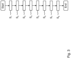
- Figure 3 shows a flow chart which shows a method for configuring a PLC device 3.
- a first application 10 is executed and this first application 10 displays a first graphical user interface 11 for generating configuration information 15 for the at least one PLC device 3.
- a second method step S 2 at least one user input on the first graphical user interface 11 is recorded by the first application 10.
- the configuration information 15 with at least one configuration parameter 14 for the at least one PLC device 3 is generated on the basis of the recorded user input by the first application 10.
- a second application 16 is executed and this displays a second graphical user interface 17 for controlling the PLC central unit 2.
- a fifth method step S 5 the configuration information 15 is transferred from the first application 10, in particular into an input field for configuring the at least one PLC device 3 on the second graphical user interface 17 of the second application 15.
- PLC configuration information is generated by the second application 16 based on the configuration information 15.
- a seventh method step S 7 the PLC configuration information to the at least one PLC device 3 by the PLC central unit 2.
- the PLC configuration information received by the PLC device 3 is loaded by the PLC device 3.
Landscapes
- Engineering & Computer Science (AREA)
- Physics & Mathematics (AREA)
- General Physics & Mathematics (AREA)
- Automation & Control Theory (AREA)
- General Engineering & Computer Science (AREA)
- Theoretical Computer Science (AREA)
- Human Computer Interaction (AREA)
- Programmable Controllers (AREA)
Abstract
Description
- Die Erfindung betrifft ein Verfahren zum Konfigurieren eines SPS-Geräts und ein SPS-Verwaltungssystem zum Ausführen des Verfahrens.
- SPS-Systeme (dt. Speicherprogrammierbare Steuerung; engl. Programmable Logic Controller (PLC)) sind computergesteuerte Systeme, die in der Automatisierungstechnik weit verbreitet sind. Die Hauptfunktion eines SPS-Systems besteht darin, industrielle Prozesse zu steuern und zu überwachen. Insbesondere werden mit einem SPS-System Abläufe in Fabriken, Maschinen und der Gebäudeautomatisierung gesteuert.
- Ein SPS-System umfasst insbesondere eine SPS-Zentraleinheit und entsprechend an die SPS-Zentraleinheit angeschlossene SPS-Geräte. Weiterhin gibt es eine Applikationssoftware, über die das SPS-System programmiert und konfiguriert werden kann. Ein SPS-System arbeitet vorzugsweise in Echtzeit und eignet sich insbesondere dazu, um Prozesse zu automatisieren, die eine hohe Genauigkeit, Zuverlässigkeit und Geschwindigkeit erfordern.
- SPS-Konfigurationen umfassen je nach Hersteller die Konfiguration einer ganzen Anlage. In der Regel bestimmt diese Konfiguration nicht nur das SPS-Programm der verwendeten Steuerungen, sondern auch die Konfiguration der angeschlossenen Komponenten. Im Falle von PROFINET wird die Konfiguration einzelner Module einer Komponente zum Start der Anlage einmalig übertragen.
- Dafür stellt das SPS-Konfigurations-Tool häufig ein generisches Interface zur Verfügung, welches das Setzen von Parametern zulässt.
- Zeitgemäße SPS-Komponenten wie Sensoren, Aktoren oder auch viele Maschinen, sind mittlerweile zu komplex, um durch einfache, wenige Parameter, welche in der SPS konfigurierbar sind, konfiguriert werden zu können. Beispielsweise gibt es für Sensoren Applikationen mit abgestimmten grafischen Benutzeroberflächen (Bediener-Schnittstellen), über die der Nutzer SPS-Gerät möglichst intuitiv parametrieren kann. Dieser graphisch unterstütze Ansatz einer Bedienerschnittstelle ist durch den generischen Ansatz von Parametern nicht ersetzbar.
- Es ist daher die Aufgabe der hier vorliegenden Erfindung ein Verfahren zu schaffen, mit welchem SPS-Geräte sehr leicht verwaltet und konfiguriert werden können.
- Die Aufgabe wird durch das erfindungsgemäße Verfahren zum Konfigurieren eines SPS-Geräts gemäß dem Anspruch 1 und durch das SPS-Verwaltungssystem gemäß dem Anspruch 15 gelöst. In den Ansprüchen 2 bis 14 sind vorteilhafte Weiterbildungen des erfindungsgemäßen Verfahrens angegeben.
- Das erfindungsgemäße Verfahren dient zum Konfigurieren eines SPS-Geräts, welches an eine SPS-Zentraleinheit angeschlossen ist, mittels einer SPS-Konfigurationsinformation. In einem ersten Verfahrensschritt wird eine erste Applikation ausgeführt und durch diese erste Applikation eine erste grafische Benutzeroberfläche zum Erzeugen einer Konfigurationsinformation für das zumindest eine SPS-Gerät dargestellt. In einem zweiten Verfahrensschritt wird zumindest eine Benutzereingabe auf der ersten grafischen Benutzeroberfläche durch die erste Applikation erfasst. In einem dritten Verfahrensschritt wird die Konfigurationsinformation mit zumindest einem Konfigurationsparameter für das zumindest eine SPS-Gerät anhand der erfassten Benutzereingabe durch die erste Applikation erzeugt. In einem vierten Verfahrensschritt wird eine zweite Applikation ausgeführt und durch diese eine zweite grafische Benutzeroberfläche zur Steuerung der SPS-Zentraleinheit dargestellt. In einem fünften Verfahrensschritt wird die Konfigurationsinformation von der ersten Applikation, insbesondere in ein Eingabefeld zum Konfigurieren des zumindest einen SPS-Geräts auf der zweiten grafischen Benutzeroberfläche der zweiten Applikation übertragen. In einem sechsten Verfahrensschritt wird anhand der Konfigurationsinformation eine SPS-Konfigurationsinformation durch die zweite Applikation erzeugt. In einem siebten Verfahrensschritt wird die SPS-Konfigurationsinformation an das zumindest eine SPS-Gerät durch die SPS-Zentraleinheit übertragen. Bevorzugt wird in einem achten Verfahrensschritt die durch das SPS-Gerät empfangene SPS-Konfigurationsinformation durch das SPS-Gerät geladen.
- Anders ausgedrückt, kann die speziell zur Konfiguration des SPS-Geräts ausgestaltete erste grafische Benutzeroberfläche für die Konfiguration des SPS-Geräts genutzt werden, wobei trotzdem die Übermittlung der Konfiguration an das SPS-Gerät zentral durch die SPS-Zentraleinheit erfolgt. Bei der ersten grafischen Benutzeroberfläche kann es sich z.B. um ein "Engineering UI" handeln. Dazu wird die Konfigurationsinformation, welche in der ersten grafischen Benutzeroberfläche erzeugt wurde, einfach an die zweite grafische Benutzeroberfläche übertragen und somit der SPS-Zentraleinheit zur Verfügung gestellt. Genauer gesagt, kann die Konfigurationsinformation z.B. im Projekt, z.B. einer Projektdatei, welche die Konfiguration der SPS-Zentraleinheit enthält, gespeichert und dann bei jedem Systemstart der SPS-Zentraleinheit an das SPS-Gerät übertragen werden. Eine direkte Verbindung zwischen der ersten Applikation und dem SPS-Gerät ist nicht notwendig. Überdies ist das Verteilen der Konfiguration auf mehrere gleichartige Anlagen einfach zu bewerkstelligen. Auch das Kopieren einer Konfiguration auf mehrere gleichartige SPS-Geräte kann durch Mehrfachverwendung der Konfigurationsinformation einfach erreicht werden.
- Es ist also besonders vorteilhaft, dass bevorzugt die gesamte Zusammenstellung der Konfiguration des SPS-Geräts, also das Erstellen der Konfigurationsinformation für das SPS-Gerät, über eine (einzige) grafische Benutzeroberfläche erfolgt. Dadurch hat der Benutzer alle Vorteile, die eine genau auf das SPS-Gerät abgestimmte Benutzeroberfläche bieten kann. Weiterhin ist es vorteilhaft, dass diese Konfigurationsinformation, die durch die erste Applikation erzeugt wird, an die zweite Applikation übertragen wird, die aus der Konfigurationsinformation die benötigte SPS-Konfigurationsinformation generiert. Diese zweite Applikation dient zur Steuerung und/oder Konfiguration der SPS-Zentraleinheit. Die zweite Applikation muss in diesem Fall nicht die auf das SPS-Gerät genau abgestimmte Benutzeroberfläche beinhalten. Dadurch ist es ausreichend, wenn die zweite Applikation lediglich diejenigen Komponenten beinhaltet, die zur allgemeinen Steuerung eines SPS-Verwaltungssystem notwendig sind. Die zweite Applikation muss daher nicht noch mit einer intuitiven Benutzeroberfläche für jedes angeschlossenes SPS-Gerät versehen werden. Dadurch kann die Konfiguration eines SPS-Verwaltungssystem besonders einfach durchgeführt werden.
- Kurz gesagt, wird also der Vorteil der einfachen und umfassenden Konfiguration durch die erste Benutzeroberfläche mit der einfachen Verteilung der Konfiguration durch die zweite Applikation kombiniert.
- Bei dem SPS-Gerät kann es sich insbesondere um ein Feldgerät handeln, welches beispielsweise als Sensor oder Aktor ausgebildet ist. Das SPS-Gerät kann z.B. einen Überwachungssensor, wie einen Laserscanner oder ein Lichtgitter, eine Motorsteuerung und dergleichen umfassen. Für unterschiedliche SPS-Geräte kann jeweils eine unterschiedliche erste Applikation und eine unterschiedliche erste grafische Benutzeroberfläche verwendet werden, die auf die Einstellungsmöglichkeiten des jeweiligen SPS-Geräts angepasst sind. Es versteht sich, dass zur Konfiguration unterschiedlicher SPS-Geräte auch, insbesondere nacheinander, verschiedene solcher erster Applikationen verwendet werden können, um verschiedene Konfigurationsinformationen für verschiedene SPS-Geräte zu erzeugen und die verschiedenen Konfigurationsinformationen an die (einzige) zweite Applikation übertragen werden, um letztlich eine Konfiguration der verschiedenen SPS-Geräte durch die SPS-Zentraleinheit vorzunehmen.
- Das SPS-Gerät verwendet bevorzugt die SPS-Konfigurationsinformationen in seinem Betrieb, wobei durch die SPS-Konfigurationsinformationen das Betriebsverhalten des SPS-Geräts geändert oder angepasst wird. Genauer gesagt, reagiert das SPS-Gerät auf den Empfang der SPS-Konfigurationsinformation bevorzugt mit einem Zurücksetzen von Parametern, insbesondere von konfigurationsrelevanten Variablen, auf Standard- bzw. Default-Wert und verarbeitet dann die SPS-Konfigurationsinformation durch entsprechendes Setzen der Parameter-Werte wie in der SPS-Konfigurationsinformation angegeben. Durch die SPS-Konfigurationsinformationen kann also das Verhalten des SPS-Geräts z.B. in einem industriellen Prozess geändert oder angepasst werden.
- In einer erfindungsgemäßen Weiterbildung werden die erste Applikation und die zweite Applikation von demselben Computersystem ausgeführt. Hierbei handelt es sich insbesondere um ein Client-Computersystem. Die Applikation kann als lokale Installation oder als entfernte Installation ausgeführt werden. Eine entfernte Installation kann beispielsweise eine webbasierte Cloudinstallation sein. Dadurch hat der Benutzer einen optimalen Überblick, um das SPS-Gerät mittels der ersten grafischen Benutzeroberfläche individuell konfigurieren zu können und sieht auch gleichzeitig die Konfigurationsmöglichkeiten des gesamten SPS-Verwaltungssystems. Es ist auch denkbar, dass die erste Applikation eine lokale Installation ist und die zweite Applikation von einem Webserver auf der SPS-Zentraleinheit bereitgestellt wird.
- In einer erfindungsgemäßen Weiterbildung umfasst der zumindest eine Konfigurationsparameter ein Name-Wert-Paar. Bevorzugt wird eine Vielzahl von Konfigurationsparametern in aufeinanderfolgenden Name-Wert-Paaren in der Konfigurationsinformation kodiert. Bei einem Name-Wert-Paar kann es sich beispielsweise um eine Variable handeln, die mit einem bestimmten Wert belegt ist. Beispielsweise kann die Aktualisierungsfrequenz eines SPS-Geräts, in Form eines SPS-Überwachungssensors, als Name-Wert-Paar den zumindest einen Konfigurationsparameter darstellen. Dadurch ist eine sehr leichte Zuordnung der zu konfigurierenden Eigenschaft des SPS-Geräts zu dem eigentlichen Wert möglich. Ein Name-Wert-Paar kann beispielsweise durch einen sogenannten CloningString dargestellt oder erzeugt werden. Neben Name-Wert-Paaren können auch CoLaA*-Schreibbefehle unter Verwendung von Variablen-Namen zur Erzeugung des Name-Wert-Paars verwendet werden. CoLaA ist ein auf sichtbaren (ASCII-Werte 0x20...0x1F) ASCII-Zeichen basierendes Protokoll.
- Bei mehreren Name-Wert-Paaren können diese in einem gemeinsamen String vorliegen und z.B. durch ein vorbestimmtes Trennzeichen (z.B. ";") getrennt sein. Die Name-Wert-Paare können insbesondere als JSON (JavaScript Object Notation) oder XML (eXtendable Markup Language) gespeichert werden, beispielsweise als JSON- und/oder XML-Datei.
- In einer vorteilhaften Weiterbildung umfasst das Name-Wert-Paar oder die mehreren Name-Wert-Paare die erfasste Einstellung durch die Benutzereingabe eines Elements auf der ersten grafischen Benutzeroberfläche. Mit anderen Worten kann beispielsweise über eine Check-Box auf der ersten grafischen Benutzeroberfläche eine Eigenschaft des SPS-Geräts, wie beispielsweise die Aktualisierungsfrequenz eines SPS-Überwachungssensors auf einem bestimmten Wert festgelegt werden. Zumindest eines oder alle, der durch den Benutzer auswählbaren Elemente auf der grafischen Benutzeroberfläche haben einen Namen, wobei je nach Auswahl ein entsprechender Wert diesem Namen zugewiesen wird und die Kombination als Name-Wert-Paar den Konfigurationsparameter darstellt, der die Konfigurationsinformation bildet.
- In einer vorteilhaften Weiterbildung ist der zumindest eine Konfigurationsparameter im Klartext und unverschlüsselt in der Konfigurationsinformation enthalten. Dies ist besonders vorteilhaft, weil dadurch der Benutzer diesen Konfigurationsparameter sehen, verstehen und diesen optional noch weiter anpassen kann. Bevorzugt ist der Konfigurationsparameter auch unsigniert.
- In einer vorteilhaften Weiterbildung wird die Konfigurationsinformation durch einen Kopieren/Einfügen-Befehl von der ersten Applikation in das Eingabefeld der zweiten grafischen Benutzeroberfläche der zweiten Applikation übertragen, bevorzugt als Text. Beispielsweise kann ein Funktionsbutton in der ersten grafischen Benutzeroberfläche die Konfiguration in die (Windows-)Zwischenablage kopieren. Dadurch ist keine aufwändige API notwendig und eine bereits vorhandene Software zur Verwaltung des SPS-Verwaltungssystems kann problemlos und ohne Anpassung weiterverwendet werden. Vorzugsweise drückt der Benutzer lediglich auf Kopieren und in der zweiten Applikation auf Einfügen. Dieser Vorgang kann ein Kopieren in eine Zwischenablage des Betriebssystems umfassen. Natürlich kann ein solches Übertragen von der ersten in die zweite Applikation auch durch eine API (Application Programming Interface) erledigt werden. Die zweite Applikation kann dazu eine API zur Verfügung stellen, über welche die erste Applikation die Konfigurationsinformation an die zweite Applikation überträgt.
- In einer vorteilhaften Weiterbildung entspricht die SPS-Konfigurationsinformation der Konfigurationsinformation. In diesem Fall kann direkt die Konfigurationsinformation, die durch die erste Applikation erstellt wird, an das entsprechende SPS-Gerät über die SPS-Zentraleinheit übertragen werden. Alternativ ist die SPS-Konfigurationsinformation aus der Konfigurationsinformation abgeleitet. Die SPS-Konfigurationsinformation unterscheidet sich beispielsweise durch eine Kodierung und/oder Verschlüsselung und/oder Signierung und/oder einem anderen Layout. Sie muss in diesem Fall nicht mehr zwingend im Klartext vorliegen.
- In einer vorteilhaften Weiterbildung wird lediglich für diejenige, über die erste grafische Benutzeroberfläche konfigurierte, Eigenschaft des SPS-Geräts ein Konfigurationsparameter der Konfigurationsinformation hinzugefügt, welche durch die Benutzereingabe (aktiv) festgelegt wird. Kann der Benutzer beispielsweise 30 Eigenschaften des SPS-Geräts über die erste Benutzeroberfläche einstellen und tut er dies lediglich für fünf Eigenschaften, so werden auch nur fünf Konfigurationsparameter der Konfigurationsinformation hinzugefügt. Es ist hier besonders vorteilhaft, dass die Konfigurationsinformation übersichtlich gehalten wird.
- In einer vorteilhaften Weiterbildung wird lediglich für diejenige, über die erste grafische Benutzeroberfläche konfigurierte, Eigenschaft des SPS-Geräts ein Konfigurationsparameter der Konfigurationsinformation hinzugefügt, welche einen Wert aufweist, der von einem Standardwert abweicht. Ist der Standardwert, für eine Aktualisierungsfrequenz eines SPS-Geräts in Form eines SPS-Überwachungssensors beispielsweise 120 Hz und wird dieser Wert auf 100 Hz geändert, so wird aufgrund der Abweichung von dem Standardwert ein Konfigurationsparameter erzeugt und der Konfigurationsinformation hinzugefügt. Wird die Aktualisierungsfrequenz nicht geändert, so wird kein Konfigurationsparameter erzeugt. Grundsätzlich gilt in diesem Fall bei Verwendung von allgemeinen CloningStrings, dass alle Variablen, also Eigenschaften des SPS-Geräts, die durch die erste grafische Benutzeroberfläche geändert werden können, mit Default-Werten verglichen werden. Dabei werden dann nur die Variablen in die CloningStrings übernommen, welche einen zu ihren Default-Werten unterschiedlichen Wert aufweisen. Dadurch wird die Gesamtgröße der CloningStrings maßgeblich reduziert. In diesem Fall kann auch von einem DifferentialCloningString gesprochen werden.
- Weiterhin kann die SPS-Konfigurationsinformation, insbesondere in der Form eines DifferentialCloningStrings, auch einen Verweis auf einen von mehreren Sätzen von Standardwerten enthalten. Ist ein Verweis auf einen Satz von Standardwerten enthalten, so kann das SPS-Gerät jeweils die entsprechenden Standardwerte verwenden. Beispielsweise kann ein erster Satz von Standardwerten einen energiesparenden Betrieb bewirken, wohingegen ein zweiter Satz von Standardwerten einen Betrieb mit z.B. hoher Abtastrate ermöglicht. Beim ersten Satz von Standardwerten kann z.B. die Abtastrate oder die Aktualisierungsfrequenz gegenüber dem zweiten Satz verringert sein.
- Ebenfalls kann die SPS-Konfigurationsinformation eine Überprüfungsinformation enthalten, beispielsweise in Form einer Checksumme oder eines Hashes. Hierdurch kann das SPS-Gerät überprüfen ob die SPS-Konfigurationsinformation korrekt übertragen wurde.
- Ein Beispiels für zumindest einen Teil einer SPS-Konfigurationsinformation ist im Folgenden angegeben:
{Backup:{Target:"CLV690-100-SWV1.23.0"},{Default:"Factory4"},{Parameter:[{Exp:1.23},{Span:45}, ... "},...],{ChkSum:0x14D 4}
Es ist zu erkennen, dass die SPS-Konfigurationsinformation das zu konfigurierende SPS-Gerät ("Target"), sowie einen Hinweis auf einen vierten Satz von Standardwerten ("Default:"Factory4"") enthält. Weiterhin umfasst die SPS-Konfigurationsinformation Informationen über eine Belichtungszeit ("EXP") und den zu erfassenden Bereich ("Span"). Auch können zusätzliche Informationen enthalten sein. Schließlich umfasst die SPS-Konfigurationsinformation noch eine Checksumme. - In einer vorteilhaften Weiterbildung wird unabhängig von der, über die erste Benutzeroberfläche konfigurierte, Eigenschaft des SPS-Geräts zumindest ein Konfigurationsparameter der Konfigurationsinformation hinzugefügt, der einen bestimmten Wert aufweist. Mit anderen Worten wird stets zumindest ein Konfigurationsparameter der Konfigurationsinformation hinzugefügt und zwar unabhängig davon, ob die diesem Konfigurationsparameter zugrunde liegende Eigenschaft über die erste grafische Benutzeroberfläche geändert wurde. Hierbei kann von einem sogenannten "White-Listing" gesprochen werden. Grundsätzlich kann eine Vorauswahl dieser zwingend zu übertragenen Konfigurationsparameter vorliegen, die beispielsweise über die erste grafische Benutzeroberfläche auch geändert werden kann. Eine derartige Vorauswahl kann nützlich sein, damit der Benutzer ein tieferes Verständnis bzgl. der Wirkungsweise des SPS-Geräts hat, wenn er die im Klartext vorliegenden Konfigurationsinformationen durchsieht.
- In einer vorteilhaften Weiterbildung wird für eine, über die erste Benutzeroberfläche konfigurierte, Eigenschaft des SPS-Geräts zumindest ein Konfigurationsparameter der Konfigurationsinformation hinzugefügt. Weiterhin wird ein weiterer Konfigurationsparameter der Konfigurationsinformation hinzugefügt, der von demjenigen Konfigurationsparameter abhängt, dessen Eigenschaft über die erste Benutzeroberfläche konfiguriert bzw. geändert wurde. Die entsprechenden Abhängigkeiten können für das jeweilige SPS-Gerät spezifisch sein und werden durch die erste Applikation verarbeitet.
- In einer vorteilhaften Weiterbildung wird für jede, über die erste Benutzeroberfläche konfigurierbare, Eigenschaft des SPS-Geräts ein Konfigurationsparameter der Konfigurationsinformation hinzugefügt. In diesem Fall umfasst die Konfigurationsinformation sämtliche Konfigurationsparameter, die durch die erste grafische Benutzeroberfläche eingestellt werden können.
- In einer vorteilhaften Weiterbildung werden eine, mehrere oder alle dieser konfigurierbaren Eigenschaften des SPS-Geräts durch eine Benutzereingabe festgelegt. Dies bedeutet, dass sämtliche Konfigurationsparameter der Konfigurationsinformation hinzugefügt werden. Dies gilt sowohl für Konfigurationsparameter, deren zugrunde liegende Eigenschaften durch die Benutzereingabe festgelegt wurden, als auch für solche Konfigurationsparameter, deren zugrunde liegende Eigenschaften nicht durch eine Benutzereingabe festgelegt wurden.
- In einer vorteilhaften Weiterbildung wird für eine vorbestimmte, über die erste Benutzeroberfläche konfigurierbare, Eigenschaft des SPS-Geräts nie ein Konfigurationsparameter der Konfigurationsinformation hinzugefügt. Dadurch wird erreicht, dass das SPS-Gerät nicht bezüglich bestimmten, beispielsweise gesperrten, Eigenschaften konfiguriert werden kann. Hierbei kann von einem sogenannten "Black-Listing" gesprochen werden. Beispielsweise ist es denkbar, dass ein Benutzer eine Eigenschaft, wonach das SPS-Gerät, beispielsweise in Form eines Überwachungssensors, nur zu bestimmten Uhrzeiten aktiv ist, nicht verändern darf.
- In einer vorteilhaften Weiterbildung ist die erste Applikation dazu ausgebildet, um dem Benutzer auf der ersten grafischen Benutzeroberfläche, in Abhängigkeit seines Benutzerrechts, unterschiedliche konfigurierbare Eigenschaften für das SPS-Gerät anzuzeigen. So kann Benutzer A weitere konfigurierbare Eigenschaften für das SPS-Gerät angezeigt bekommen als Benutzer B.
- In einer vorteilhaften Weiterbildung initialisiert das SPS-Gerät Konfigurationsparameter, die nicht in der SPS-Konfigurationsinformation enthalten sind, mit einem Standardwert. Es müssen daher nur die aktuell eingestellten Konfigurationsparameter an das SPS-Gerät übertragen werden.
- In einer vorteilhaften Weiterbildung überträgt das SPS-Gerät seine aktuelle Konfiguration als Konfigurationsinformation an die SPS-Zentraleinheit, wobei die SPS-Zentraleinheit dazu ausgebildet ist, um die Konfigurationsinformation des SPS-Geräts an die erste Applikation zu übertragen, die wiederum dazu ausgebildet ist, um diese zu empfangen und die empfangene Konfigurationsinformation des SPS-Geräts auf der ersten grafischen Benutzeroberfläche darzustellen. Dadurch kann ein Benutzer zusätzliche Änderungen auf der gewohnten Benutzeroberfläche machen. Das Übertragen der empfangenen Konfigurationsinformation von der ersten Applikation auf die zweite Applikation kann durch einen Kopieren/Einfügen-Befehl erfolgen. Es ist auch denkbar, dass die empfangene Konfigurationsinformation nur diejenigen Konfigurationsparameter umfasst, die sich von einer Standardeinstellung unterscheiden. Die zweite Applikation verwendet dann für Konfigurationsparameter, die nicht in der Konfigurationsinformation enthalten sind, Standardwerte.
- In einer vorteilhaften Weiterbildung ist die erste Applikation dazu ausgebildet, um ein Auswahlmenü auf der ersten grafischen Benutzeroberfläche darzustellen, welches es dem Benutzer erlaubt das zu konfigurierende SPS-Gerät auszuwählen, wobei je nach ausgewähltem SPS-Gerät unterschiedliche GUI-Elemente auf der ersten grafischen Benutzeroberfläche erscheinen. Dies ist insbesondere dann vorteilhaft, wenn ein Hersteller eines SPS-Geräts verschiedene SPS-Geräte (Sensoren, Aktoren, Maschinen) im Programm hat und so lediglich eine Applikation aktualisieren und der Benutzer lediglich eine erste Applikation installieren muss.
- In einer vorteilhaften Weiterbildung umfasst die erste Applikation mehr Elemente auf der ersten grafischen Benutzeroberfläche zur Konfiguration des entsprechenden SPS-Geräts als die zweite Applikation auf der zweiten grafischen Benutzeroberfläche. Vorzugsweise umfasst die zweite Applikation keine Elemente auf der zweiten grafischen Benutzeroberfläche, mit denen das entsprechende SPS-Gerät konfiguriert werden kann.
- Das erfindungsgemäße SPS-Verwaltungssystem umfasst eine SPS-Zentraleinheit, zumindest ein SPS-Gerät und ein Computersystem. Das zumindest eine SPS-Gerät und das Computersystem sind an die SPS-Zentraleinheit angeschlossen. Das Computersystem ist dazu ausgebildet, um die erste und die zweite Applikation auszuführen. Das SPS-Verwaltungssystem ist dazu ausgebildet, um das eingangs beschriebene Verfahren auszuführen.
- In einer vorteilhaften Weiterbildung ist das zumindest eine SPS-Gerät über PROFINET mit der SPS-Zentraleinheit verbunden.
- In einer vorteilhaften Weiterbildung ist das Computersystem über eine Ethernetverbindung oder WIFI-Verbindung oder Mobilfunkverbindung oder Bluetooth®-Verbindung mit der SPS-Zentraleinheit verbunden. Bevorzugt kann die SPS-Zentraleinheit mit dem SPS-Gerät über eine kabelgebundene Datenverbindung, insbesondere einen Feldbus, z.B. PROFINET, EtherCAT, SERCOS, EtherNet/IP und dergleichen verbunden sein.
- Nachfolgend wird die Erfindung rein beispielhaft unter Bezugnahme auf die Zeichnungen beschrieben. Es zeigen:
- Figur 1:
- eine Übersicht des SPS-Verwaltungssystems mit mehreren SPS-Geräten, einer SPS-Zentraleinheit und einem Computersystem;
- Figur 2:
- das Computersystem, auf dem die erste und die zweite Applikation ausgeführt werden; und
- Figur 3:
- ein Flussdiagramm, welches ein Verfahren zum Konfigurieren eines SPS-Geräts zeigt.
-
Figur 1 zeigt eine Übersicht über das erfindungsgemäße SPS-Verwaltungssystem 1. Das SPS-Verwaltungssystem umfasst eine SPS-Zentraleinheit 2, zumindest ein SPS-Gerät 3 und ein Computersystem 4. Das zumindest eine SPS-Gerät 3 ist über eine erste Datenverbindung 5, insbesondere über einen PROFIBUS, mit der SPS-Zentraleinheit 2 verbunden. Das Computersystem 4 ist über eine zweite Datenverbindung 6, insbesondere über eine Ethernetverbindung oder WIFI-Verbindung oder Mobilfunkverbindung oder Bluetooth®-Verbindung, mit der SPS-Zentraleinheit 2 verbunden. - Das zumindest eine SPS-Gerät 3 umfasst in diesem Ausführungsbeispiel einen Überwachungssensor 3a, eine Sicherheitszuhaltung 3b, eine Tür 3c und eine Maschine 3d.
- Die Maschine 3d ist in einem durch Gitter 7 abgegrenzten Raum 8 angeordnet. Die Überwachungssensoren 3a sind dazu ausgebildet, um die Präsenz einer Person in dem zu überwachenden Raum 8 festzustellen. Die Sicherheitszuhaltungen 3b sind dazu ausgebildet, um zu detektieren, ob eine Tür 3c, die in den Raum 8 hineinführt, geöffnet oder geschlossen ist und/oder um diese Tür 3c zu verriegeln. Die Tür 3c kann auch über einen Antrieb verfügen, wobei z.B. die Öffnungsgeschwindigkeit einstellbar ist.
- Die SPS-Zentraleinheit 2 steuert die SPS-Geräte 3 während des Starts und während dem Betrieb des SPS-Verwaltungssystems 1 an. Die SPS-Geräte 3 können über das Computersystem 4 konfiguriert werden. Auch die SPS-Zentraleinheit 2 kann über das Computersystem 4 konfiguriert werden.
-
Figur 2 zeigt das Computersystem 4 und erläutert wie über das Computersystem 4 die SPS-Geräte 3 konfiguriert werden können. Das Computersystem 4 ist dazu ausgebildet, um eine erste Applikation 10 auszuführen. Die erste Applikation 10 umfasst eine erste grafische Benutzeroberfläche 11. In diesem Ausführungsbeispiel dient die erste Applikation 10 dazu, um ein SPS-Gerät 3 in Form des Überwachungssensors 3a zu konfigurieren. Die grafische Benutzeroberfläche 11 der ersten Applikation 10 ist explizit auf die möglichen Einstellungen des Überwachungssensors 3a zugeschnitten. Ein Benutzer kann daher sehr intuitiv den Überwachungssensor 3a konfigurieren. - Grundsätzlich kann es für jedes SPS-Gerät 3 eine eigene erste Applikation 10 geben. Es ist auch denkbar, dass es lediglich eine erste Applikation 10 gibt und der Benutzer beim Starten dieser ersten Applikation 10 das zu konfigurierende SPS-Gerät 3 auswählt. In Abhängigkeit diese Auswahl wäre die erste Applikation 10 dann dazu ausgebildet, um die passende erste Benutzeroberfläche 11 anzuzeigen, mit welcher der Benutzer das ausgewählte SPS-Gerät 3 konfigurieren kann.
- In dem Ausführungsbeispiel kann der Benutzer sechs verschiedene Eigenschaften 12 des SPS-Geräts 3 in Form des Überwachungssensors 3a konfigurieren. Die zu konfigurierenden Eigenschaften 12 haben die Namen N1, N2, N3, N4, N5 und N6. Die Eigenschaften 12 können über verschiedene GUI-Elemente eingestellt werden. Die erste Benutzeroberfläche 11 der ersten Applikation 10 stellt in diesem Ausführungsbeispiel Schieberegler und Eingabefelder zur Verfügung. Selbstverständlich kann es auch Drop-Down-Menüs oder Optionsschaltflächen geben.
- Der Benutzer kann die Konfiguration über ein Eingabegerät, wie eine Tastatur und/oder Maus vornehmen. Selbstverständlich kann die Konfiguration auch durch Berührung eines berührungsempfindlichen Bildschirms vorgenommen werden. In diesem Ausführungsbeispiel ist ein Mauszeiger 13 dargestellt, der gerade einen Schieberegler anklickt, um den Wert der Eigenschaft 12 mit dem Namen N1 zu verändern. Beispielsweise ist es denkbar, dass der Benutzer über den Schieberegler die Aktualisierungsfrequenz des Überwachungssensors 3a ändert.
- Jede Eigenschaft 12 des SPS-Geräts 3, die der Benutzer konfigurieren kann, umfasst einen Namen und einen entsprechenden Wert. Die Namen sind in diesem Ausführungsbeispiel mit N1, N2, N3, N4, N5 und N6 bezeichnet. Die Werte sind in diesem Ausführungsbeispiel mit V1, V2, V3, V4, V5 und V6 bezeichnet.
- Ein solches Namen-Werte-Paar, also N1 mit V1, kann auch als Konfigurationsparameter 14 bezeichnet werden. Die Konfigurationsparameter 14 liegen insbesondere im Klartext vor, sodass ein Benutzer sehr schnell überprüfen kann, ob er die richtigen Einstellungen für das SPS-Gerät 3 vorgenommen hat.
- Die erste Applikation 10 ist dazu ausgebildet, um Benutzereingaben auf der ersten grafischen Benutzeroberfläche 11 zu erkennen und in Abhängigkeit der vorgenommenen Änderungen der Eigenschaften 12 entsprechende Konfigurationsparameter 14 zu erzeugen und diese einer Konfigurationsinformation 15 hinzuzufügen. Eine Konfigurationsinformation 15 kann daher einen oder mehrere Konfigurationsparameter 14 enthalten.
- Die erste Applikation 10 ist dazu ausgebildet, um für sämtliche einzustellende Eigenschaften 12 des SPS-Geräts Konfigurationsparameter 14 zu erzeugen und diese der Konfigurationsinformation 15 hinzuzufügen. Bevorzugt ist die erste Applikation 10 allerdings dazu ausgebildet, um lediglich für diejenigen einzustellenden Eigenschaften 12 des SPS-Geräts 3 Konfigurationsparameter 14 zu erzeugen und diese der Konfigurationsinformation 15 hinzuzufügen, die geändert wurden und/oder die von einem vorgegebenen Standardwert abweichen. Dadurch kann die Größe der Konfigurationsinformation 15 klein gehalten werden.
- Das Computersystem 4 ist weiter dazu ausgebildet, um eine zweite Applikation 16 auszuführen. Die zweite Applikation 16 umfasst eine zweite grafische Benutzeroberfläche 17. In diesem Ausführungsbeispiel dient die zweite Applikation 16 dazu, um die SPS-Zentraleinheit 2 zu konfigurieren. SPS-Geräte 3, die an die SPS-Zentraleinheit 2 angeschlossen sind, werden beispielsweise auf der zweiten grafischen Benutzeroberfläche 17 angezeigt. Der Benutzer kann beispielsweise eines dieser SPS-Geräte 3 auswählen. In diesem Fall hat der Benutzer den Überwachungssensor 3a ausgewählt. In diesem Ausführungsbeispiel wird die Auswahl dadurch visualisiert, dass das Bild für das ausgewählte SPS-Gerät 3 etwas kräftiger bzw. in einer anderen Farbe bzw. mit einer Umrandung dargestellt ist. Gleichzeitig ist die zweite Applikation 16 dazu ausgebildet, um ein Eingabefeld 18 darzustellen, in welcher die durch die erste Applikation 10 erzeugte Konfigurationsinformation 15 eingefügt werden kann. Dieses Einfügen kann durch einen Kopieren/Einfügen-Befehl erfolgen. In
Figur 2 ist die Konfigurationsinformation 15 mit den Konfigurationsparametern 14 von der ersten Applikation 10 in das entsprechende Eingabefeld 18 der zweiten grafischen Benutzeroberfläche 17 zweiten Applikation 16 eingefügt. Die zweite Applikation 16 ist dazu ausgebildet, um aus der Konfigurationsinformation 15 eine SPS-Konfigurationsinformation zu erzeugen. Diese SPS-Konfigurationsinformation wird mittels der zweiten Applikation 16 zu der SPS-Zentraleinheit 2 übertragen. Die SPS-Zentraleinheit 2 ist dazu ausgebildet, um diese SPS-Konfigurationsinformation zu dem angeschlossenen entsprechenden SPS-Gerät 3 zu übertragen. Das entsprechende SPS-Gerät 3 ist wiederum dazu ausgebildet, um die empfangene SPS-Konfigurationsinformation zu laden und sich entsprechend dieser SPS-Konfigurationsinformation zu konfigurieren. -
Figur 3 zeigt ein Flussdiagramm, welches ein Verfahren zum Konfigurieren eines SPS-Geräts 3 zeigt. In einem ersten Verfahrensschritt S1 wird eine erste Applikation 10 ausgeführt und durch diese erste Applikation 10 eine erste grafische Benutzeroberfläche 11 zum Erzeugen einer Konfigurationsinformation 15 für das zumindest eine SPS-Gerät 3 dargestellt. In einem zweiten Verfahrensschritt S2 wird zumindest eine Benutzereingabe auf der ersten grafischen Benutzeroberfläche 11 durch die erste Applikation 10 erfasst. In einem dritten Verfahrensschritt S3 wird die Konfigurationsinformation 15 mit zumindest einem Konfigurationsparameter 14 für das zumindest eine SPS-Gerät 3 anhand der erfassten Benutzereingabe durch die erste Applikation 10 erzeugt. In einem vierten Verfahrensschritt S4 wird eine zweite Applikation 16 ausgeführt und durch diese eine zweite grafische Benutzeroberfläche 17 zur Steuerung der SPS-Zentraleinheit 2 dargestellt. In einem fünften Verfahrensschritt S5 wird die Konfigurationsinformation 15 von der ersten Applikation 10, insbesondere in ein Eingabefeld zum Konfigurieren des zumindest einen SPS-Geräts 3 auf der zweiten grafischen Benutzeroberfläche 17 der zweiten Applikation 15 übertragen. In einem sechsten Verfahrensschritt S6 wird anhand der Konfigurationsinformation 15 eine SPS-Konfigurationsinformation durch die zweite Applikation 16 erzeugt. In einem siebten Verfahrensschritt S7 wird die SPS-Konfigurationsinformation an das zumindest eine SPS-Gerät 3 durch die SPS-Zentraleinheit 2 übertragen. In einem achten Verfahrensschritt Sswird die durch das SPS-Gerät 3 empfangene SPS-Konfigurationsinformation durch das SPS-Gerät 3 geladen. - Die Erfindung ist nicht auf die beschriebenen Ausführungsbeispiele beschränkt. Im Rahmen der Erfindung sind alle beschriebenen und/oder gezeichneten Merkmale beliebig miteinander kombinierbar, sofern nicht etwas Gegenteiliges angegeben ist.
Bezugszeichenliste SPS-Verwaltungssystem 1 SPS-Zentraleinheit 2 SPS-Gerät 3 Überwachungssensor (SPS) 3a Sicherheitszuhaltung (SPS) 3b Tür (SPS) 3c Maschine (SPS) 3d Computersystem 4 Erste Datenverbindung 5 Zweite Datenverbindung 6 Gitter 7 Raum 8 Erste Applikation 10 Erste grafische Benutzeroberfläche 11 Eigenschaften des SPS-Geräts 12 Mauszeiger 13 Konfigurationsparameter 14 Konfigurationsinformation 15 Zweite Applikation 16 Zweite grafische Benutzeroberfläche 17 Eingabefeld 18 Verfahrensschritte S1, S2, S3, S4, S5, S6, S7, S8
Claims (15)
- Verfahren zum Konfigurieren eines SPS-Geräts (3), welches an eine SPS-Zentraleinheit (2) angeschlossen ist, mit einer SPS-Konfigurationsinformation mit den folgenden Verfahrensschritten:- Ausführen (S1) einer ersten Applikation (10) und Darstellen einer ersten grafischen Benutzeroberfläche (11) zum Erzeugen einer Konfigurationsinformation (15) für das zumindest eine SPS-Gerät (3) durch die erste Applikation (10);- Erfassen (S2) zumindest einer Benutzereingabe auf der ersten grafischen Benutzeroberfläche (11) durch die erste Applikation (10);- Erzeugen (S3) der Konfigurationsinformation (15) mit zumindest einem Konfigurationsparameter (14) für das zumindest eine SPS-Gerät (3) anhand der erfassten Benutzereingabe durch die erste Applikation (10);- Ausführen (S4) einer zweiten Applikation (16) und Darstellen einer zweiten grafischen Benutzeroberfläche (17) zur Steuerung der SPS-Zentraleinheit (2) durch die zweite Applikation (16);- Übertragen (S5) der Konfigurationsinformation (15) von der ersten Applikation (10) in ein Eingabefeld (18) zum Konfigurieren des zumindest einen SPS-Geräts (3) auf der zweiten grafischen Benutzeroberfläche (17) der zweiten Applikation (16);- Erzeugen (S6) der SPS-Konfigurationsinformation anhand der Konfigurationsinformation (15) durch die zweite Applikation (16);- Übertragen (S7) der SPS-Konfigurationsinformation an das zumindest eine SPS-Gerät (3) durch die SPS-Zentraleinheit (2).
- Verfahren nach Anspruch 1,
wobei die erste Applikation (10) und die zweite Applikation (16) von demselben Computersystem (4) ausgeführt werden. - Verfahren nach Anspruch 1 oder 2,
wobei der zumindest eine Konfigurationsparameter (14) ein Name-Wert-Paar oder mehrere Name-Wert-Paare umfasst. - Verfahren nach Anspruch 3,
wobei das Name-Wert-Paar oder die mehreren Name-Wert-Paare die erfasste Einstellung durch die Benutzereingabe eines Elements auf der ersten grafischen Benutzeroberfläche (11) umfasst. - Verfahren nach einem der vorstehenden Ansprüche,
wobei der zumindest eine Konfigurationsparameter (14) im Klartext und unverschlüsselt in der Konfigurationsinformation (15) enthalten ist. - Verfahren nach einem der vorstehenden Ansprüche,
wobei die Konfigurationsinformation (15) durch einen Kopieren/Einfügen-Befehl von der ersten Applikation (10) in das Eingabefeld (18) der zweiten grafischen Benutzeroberfläche (17) der zweiten Applikation (16) übertragen wird. - Verfahren nach einem der vorstehenden Ansprüche,
wobei die SPS-Konfigurationsinformation der Konfigurationsinformation (15) entspricht oder wobei die SPS-Konfigurationsinformation aus der Konfigurationsinformation (15) abgeleitet wird. - Verfahren nach einem der vorstehenden Ansprüche,
wobei lediglich für diejenige, über die erste grafische Benutzeroberfläche (11) konfigurierte, Eigenschaft (12) des SPS-Geräts (3) ein Konfigurationsparameter (14) der Konfigurationsinformation (15) hinzugefügt wird, welche durch die Benutzereingabe festgelegt wird. - Verfahren nach einem der vorstehenden Ansprüche,
wobei lediglich für diejenige, über die erste grafische Benutzeroberfläche (11) konfigurierte, Eigenschaft (12) des SPS-Geräts (3) ein Konfigurationsparameter (14) der Konfigurationsinformation (15) hinzugefügt wird, welche einen Wert aufweist, der von einem Standardwert abweicht. - Verfahren nach einem der Ansprüche 8 und 9,
wobei unabhängig von der, über die erste Benutzeroberfläche (11) konfigurierte, Eigenschaft (12) des SPS-Geräts (3) zumindest ein Konfigurationsparameter (14) der Konfigurationsinformation (15) hinzugefügt wird, der einen bestimmten Wert aufweist. - Verfahren nach einem der Ansprüche 1 bis 7,
wobei für jede, über die erste Benutzeroberfläche (11) konfigurierbare, Eigenschaft (12) des SPS-Geräts (3) ein Konfigurationsparameter (14) der Konfigurationsinformation (15) hinzugefügt wird. - Verfahren nach Anspruch 11,
wobei eine, mehrere oder alle dieser konfigurierbaren Eigenschaften (12) des SPS-Geräts (3) durch eine Benutzereingabe festgelegt werden. - Verfahren nach einem der Ansprüche 11 oder 12,
wobei für eine bestimmte, über die erste Benutzeroberfläche (11) konfigurierbare, Eigenschaft (12) des SPS-Geräts (3) nie ein Konfigurationsparameter (14) der Konfigurationsinformation (15) hinzugefügt wird. - Verfahren nach einem der vorstehenden Ansprüche,
wobei das SPS-Gerät (3) Konfigurationsparameter (14), die nicht in der SPS-Konfigurationsinformation enthalten sind, mit einem Standardwert initialisiert. - SPS-Verwaltungssystem (1) mit einer SPS-Zentraleinheit (2), zumindest einem SPS-Gerät (3) und einem Computersystem (4), wobei das zumindest eine SPS-Gerät (3) und das Computersystem (4) an die SPS-Zentraleinheit (2) angeschlossen sind, wobei das Computersystem (4) dazu ausgebildet ist, um die erste Applikation (10) und die zweite Applikation (16) auszuführen, wobei das SPS-Verwaltungssystem (1) dazu ausgebildet ist, um das Verfahren nach einem der vorherigen Ansprüche auszuführen.
Priority Applications (2)
| Application Number | Priority Date | Filing Date | Title |
|---|---|---|---|
| EP23191936.6A EP4509935B1 (de) | 2023-08-17 | 2023-08-17 | Verfahren zum konfigurieren eines sps-geräts und ein sps-verwaltungssystem zum ausführen des verfahrens |
| US18/807,035 US20250060868A1 (en) | 2023-08-17 | 2024-08-16 | Verfahren zum Konfigurieren eines SPS-Geräts und ein SPS-Verwaltungssystem zum Ausführen des Verfahrens |
Applications Claiming Priority (1)
| Application Number | Priority Date | Filing Date | Title |
|---|---|---|---|
| EP23191936.6A EP4509935B1 (de) | 2023-08-17 | 2023-08-17 | Verfahren zum konfigurieren eines sps-geräts und ein sps-verwaltungssystem zum ausführen des verfahrens |
Publications (2)
| Publication Number | Publication Date |
|---|---|
| EP4509935A1 true EP4509935A1 (de) | 2025-02-19 |
| EP4509935B1 EP4509935B1 (de) | 2025-10-01 |
Family
ID=87695848
Family Applications (1)
| Application Number | Title | Priority Date | Filing Date |
|---|---|---|---|
| EP23191936.6A Active EP4509935B1 (de) | 2023-08-17 | 2023-08-17 | Verfahren zum konfigurieren eines sps-geräts und ein sps-verwaltungssystem zum ausführen des verfahrens |
Country Status (2)
| Country | Link |
|---|---|
| US (1) | US20250060868A1 (de) |
| EP (1) | EP4509935B1 (de) |
Citations (2)
| Publication number | Priority date | Publication date | Assignee | Title |
|---|---|---|---|---|
| EP1710647A2 (de) * | 2005-04-08 | 2006-10-11 | ABB PATENT GmbH | Integration von Feldgeräten in ein Automatisierungssystem |
| DE102013112140A1 (de) * | 2013-11-05 | 2015-05-07 | Endress + Hauser Wetzer Gmbh + Co Kg | Verfahren zum Bedienen eines Feldgerätes |
-
2023
- 2023-08-17 EP EP23191936.6A patent/EP4509935B1/de active Active
-
2024
- 2024-08-16 US US18/807,035 patent/US20250060868A1/en active Pending
Patent Citations (2)
| Publication number | Priority date | Publication date | Assignee | Title |
|---|---|---|---|---|
| EP1710647A2 (de) * | 2005-04-08 | 2006-10-11 | ABB PATENT GmbH | Integration von Feldgeräten in ein Automatisierungssystem |
| DE102013112140A1 (de) * | 2013-11-05 | 2015-05-07 | Endress + Hauser Wetzer Gmbh + Co Kg | Verfahren zum Bedienen eines Feldgerätes |
Also Published As
| Publication number | Publication date |
|---|---|
| EP4509935B1 (de) | 2025-10-01 |
| US20250060868A1 (en) | 2025-02-20 |
Similar Documents
| Publication | Publication Date | Title |
|---|---|---|
| DE102007045729B4 (de) | System und Verfahren der Kommunikation zwischen zwei Prozesssteuerungen innerhalb eines Prozesssteuerungssystems | |
| EP2980662B1 (de) | Schutz einer automatisierungskomponente vor programmmanipulationen durch signaturabgleich | |
| EP2098926B1 (de) | Verfahren und Vorrichtung zum Programmieren und/oder Konfigurieren einer Sicherheitssteuerung | |
| DE102008010864A1 (de) | Verfahren zum Betreiben eines Feldgerätes | |
| EP2453326A1 (de) | Verfahren und System zur Bedienung einer Maschine aus der Automatisierungstechnik | |
| DE102012110132A1 (de) | Sparkline-Darstellungen von Prozessleitsystem-Alarmen | |
| EP1714197B1 (de) | Gerätetreiber für feldgeräte der prozessautomatisierungstechnik | |
| DE102017215508A1 (de) | Automatisierungssystem mit mindestens einem Feldgerät und mindestens einer Steuereinheit | |
| DE102014016180B4 (de) | Verfahren und Einrichtung zur Verwaltung und Konfiguration von Feldgeräten einer Automatisierungsanlage | |
| EP2098928A1 (de) | Verfahren und Vorrichtung zum Programmieren und/oder Konfigurieren einer Sicherheitssteuerung | |
| EP3282329A1 (de) | Verfahren und system zum ferngesteuerten bedienen eines feldgeräts der prozessautomatisierung | |
| EP2701019B1 (de) | Verfahren zur Parametrierung eines Feldgerätes und entsprechendes System zur Parametrierung | |
| EP3652597B1 (de) | Automatische bewertung eines maschinenverhaltens | |
| EP3396479B1 (de) | Engineering-system | |
| DE102007054925B4 (de) | Verfahren zur Überwachung eines Netzwerkes der Prozessautomatisierungstechnik | |
| EP4509935B1 (de) | Verfahren zum konfigurieren eines sps-geräts und ein sps-verwaltungssystem zum ausführen des verfahrens | |
| DE102018128502A1 (de) | Verfahren und Vorrichtung zur Bedienung und Steuerung einer maschinentechnischen Anlage mit Hilfe einer grafischen Entwicklungsoberfläche und Erzeugung einer Feldbus-Konfiguration | |
| EP3964905A1 (de) | Nutzerspezifische abhängigkeiten zwischen digitalen repräsentationen von prozessobjekten | |
| AT512963B1 (de) | Programmiervorlage für verteilte Anwendungsprogramme | |
| DE102016119744A1 (de) | Verfahren und System zum Verhindern eines unerwünschten Zugriffs auf ein Feldgerät | |
| EP3757688B1 (de) | Verfahren zur konfiguration einer industriellen maschine | |
| EP2618522A1 (de) | Verfahren zum rechnergestützten Entwurf einer Automatisierungsanlage | |
| EP3427143B1 (de) | Verfahren zum erzeugen und aktualisieren einer fernen instanz einer schirmansicht | |
| DE10215121A1 (de) | Verfahren zum Projektieren und/oder Betreiben einer Automatisierungseinrichtung | |
| DE102008057003B4 (de) | Verfahren zur sicheren Parametierung von AS Interface Slaves |
Legal Events
| Date | Code | Title | Description |
|---|---|---|---|
| PUAI | Public reference made under article 153(3) epc to a published international application that has entered the european phase |
Free format text: ORIGINAL CODE: 0009012 |
|
| STAA | Information on the status of an ep patent application or granted ep patent |
Free format text: STATUS: REQUEST FOR EXAMINATION WAS MADE |
|
| 17P | Request for examination filed |
Effective date: 20241219 |
|
| AK | Designated contracting states |
Kind code of ref document: A1 Designated state(s): AL AT BE BG CH CY CZ DE DK EE ES FI FR GB GR HR HU IE IS IT LI LT LU LV MC ME MK MT NL NO PL PT RO RS SE SI SK SM TR |
|
| GRAP | Despatch of communication of intention to grant a patent |
Free format text: ORIGINAL CODE: EPIDOSNIGR1 |
|
| STAA | Information on the status of an ep patent application or granted ep patent |
Free format text: STATUS: GRANT OF PATENT IS INTENDED |
|
| INTG | Intention to grant announced |
Effective date: 20250324 |
|
| GRAS | Grant fee paid |
Free format text: ORIGINAL CODE: EPIDOSNIGR3 |
|
| GRAA | (expected) grant |
Free format text: ORIGINAL CODE: 0009210 |
|
| STAA | Information on the status of an ep patent application or granted ep patent |
Free format text: STATUS: THE PATENT HAS BEEN GRANTED |
|
| AK | Designated contracting states |
Kind code of ref document: B1 Designated state(s): AL AT BE BG CH CY CZ DE DK EE ES FI FR GB GR HR HU IE IS IT LI LT LU LV MC ME MK MT NL NO PL PT RO RS SE SI SK SM TR |
|
| REG | Reference to a national code |
Ref country code: GB Ref legal event code: FG4D Free format text: NOT ENGLISH Ref country code: CH Ref legal event code: F10 Free format text: ST27 STATUS EVENT CODE: U-0-0-F10-F00 (AS PROVIDED BY THE NATIONAL OFFICE) Effective date: 20251001 |
|
| REG | Reference to a national code |
Ref country code: DE Ref legal event code: R096 Ref document number: 502023001888 Country of ref document: DE |
|
| REG | Reference to a national code |
Ref country code: IE Ref legal event code: FG4D Free format text: LANGUAGE OF EP DOCUMENT: GERMAN |
|
| REG | Reference to a national code |
Ref country code: NL Ref legal event code: MP Effective date: 20251001 |
|
| PG25 | Lapsed in a contracting state [announced via postgrant information from national office to epo] |
Ref country code: NL Free format text: LAPSE BECAUSE OF FAILURE TO SUBMIT A TRANSLATION OF THE DESCRIPTION OR TO PAY THE FEE WITHIN THE PRESCRIBED TIME-LIMIT Effective date: 20251001 |
|
| PG25 | Lapsed in a contracting state [announced via postgrant information from national office to epo] |
Ref country code: ES Free format text: LAPSE BECAUSE OF FAILURE TO SUBMIT A TRANSLATION OF THE DESCRIPTION OR TO PAY THE FEE WITHIN THE PRESCRIBED TIME-LIMIT Effective date: 20251001 |
|
| REG | Reference to a national code |
Ref country code: LT Ref legal event code: MG9D |
|
| PG25 | Lapsed in a contracting state [announced via postgrant information from national office to epo] |
Ref country code: NO Free format text: LAPSE BECAUSE OF FAILURE TO SUBMIT A TRANSLATION OF THE DESCRIPTION OR TO PAY THE FEE WITHIN THE PRESCRIBED TIME-LIMIT Effective date: 20260101 |
|
| PG25 | Lapsed in a contracting state [announced via postgrant information from national office to epo] |
Ref country code: FI Free format text: LAPSE BECAUSE OF FAILURE TO SUBMIT A TRANSLATION OF THE DESCRIPTION OR TO PAY THE FEE WITHIN THE PRESCRIBED TIME-LIMIT Effective date: 20251001 Ref country code: HR Free format text: LAPSE BECAUSE OF FAILURE TO SUBMIT A TRANSLATION OF THE DESCRIPTION OR TO PAY THE FEE WITHIN THE PRESCRIBED TIME-LIMIT Effective date: 20251001 |
|
| PG25 | Lapsed in a contracting state [announced via postgrant information from national office to epo] |
Ref country code: RS Free format text: LAPSE BECAUSE OF FAILURE TO SUBMIT A TRANSLATION OF THE DESCRIPTION OR TO PAY THE FEE WITHIN THE PRESCRIBED TIME-LIMIT Effective date: 20260101 |
|
| PG25 | Lapsed in a contracting state [announced via postgrant information from national office to epo] |
Ref country code: IS Free format text: LAPSE BECAUSE OF FAILURE TO SUBMIT A TRANSLATION OF THE DESCRIPTION OR TO PAY THE FEE WITHIN THE PRESCRIBED TIME-LIMIT Effective date: 20260201 |
|
| PG25 | Lapsed in a contracting state [announced via postgrant information from national office to epo] |
Ref country code: PT Free format text: LAPSE BECAUSE OF FAILURE TO SUBMIT A TRANSLATION OF THE DESCRIPTION OR TO PAY THE FEE WITHIN THE PRESCRIBED TIME-LIMIT Effective date: 20260202 Ref country code: CZ Free format text: LAPSE BECAUSE OF FAILURE TO SUBMIT A TRANSLATION OF THE DESCRIPTION OR TO PAY THE FEE WITHIN THE PRESCRIBED TIME-LIMIT Effective date: 20251001 |
|
| PG25 | Lapsed in a contracting state [announced via postgrant information from national office to epo] |
Ref country code: PL Free format text: LAPSE BECAUSE OF FAILURE TO SUBMIT A TRANSLATION OF THE DESCRIPTION OR TO PAY THE FEE WITHIN THE PRESCRIBED TIME-LIMIT Effective date: 20251001 |
|
| PG25 | Lapsed in a contracting state [announced via postgrant information from national office to epo] |
Ref country code: LV Free format text: LAPSE BECAUSE OF FAILURE TO SUBMIT A TRANSLATION OF THE DESCRIPTION OR TO PAY THE FEE WITHIN THE PRESCRIBED TIME-LIMIT Effective date: 20251001 |
|
| PG25 | Lapsed in a contracting state [announced via postgrant information from national office to epo] |
Ref country code: BG Free format text: LAPSE BECAUSE OF FAILURE TO SUBMIT A TRANSLATION OF THE DESCRIPTION OR TO PAY THE FEE WITHIN THE PRESCRIBED TIME-LIMIT Effective date: 20251001 |