EP4509907A1 - Anti-peep display screen, vehicle-mounted display device and vehicle - Google Patents
Anti-peep display screen, vehicle-mounted display device and vehicle Download PDFInfo
- Publication number
- EP4509907A1 EP4509907A1 EP23214888.2A EP23214888A EP4509907A1 EP 4509907 A1 EP4509907 A1 EP 4509907A1 EP 23214888 A EP23214888 A EP 23214888A EP 4509907 A1 EP4509907 A1 EP 4509907A1
- Authority
- EP
- European Patent Office
- Prior art keywords
- sub
- peep
- electrode
- display screen
- liquid crystal
- Prior art date
- Legal status (The legal status is an assumption and is not a legal conclusion. Google has not performed a legal analysis and makes no representation as to the accuracy of the status listed.)
- Granted
Links
Images



Classifications
-
- G—PHYSICS
- G02—OPTICS
- G02F—OPTICAL DEVICES OR ARRANGEMENTS FOR THE CONTROL OF LIGHT BY MODIFICATION OF THE OPTICAL PROPERTIES OF THE MEDIA OF THE ELEMENTS INVOLVED THEREIN; NON-LINEAR OPTICS; FREQUENCY-CHANGING OF LIGHT; OPTICAL LOGIC ELEMENTS; OPTICAL ANALOGUE/DIGITAL CONVERTERS
- G02F1/00—Devices or arrangements for the control of the intensity, colour, phase, polarisation or direction of light arriving from an independent light source, e.g. switching, gating or modulating; Non-linear optics
- G02F1/01—Devices or arrangements for the control of the intensity, colour, phase, polarisation or direction of light arriving from an independent light source, e.g. switching, gating or modulating; Non-linear optics for the control of the intensity, phase, polarisation or colour
- G02F1/13—Devices or arrangements for the control of the intensity, colour, phase, polarisation or direction of light arriving from an independent light source, e.g. switching, gating or modulating; Non-linear optics for the control of the intensity, phase, polarisation or colour based on liquid crystals, e.g. single liquid crystal display cells
- G02F1/1323—Arrangements for providing a switchable viewing angle
-
- B—PERFORMING OPERATIONS; TRANSPORTING
- B60—VEHICLES IN GENERAL
- B60K—ARRANGEMENT OR MOUNTING OF PROPULSION UNITS OR OF TRANSMISSIONS IN VEHICLES; ARRANGEMENT OR MOUNTING OF PLURAL DIVERSE PRIME-MOVERS IN VEHICLES; AUXILIARY DRIVES FOR VEHICLES; INSTRUMENTATION OR DASHBOARDS FOR VEHICLES; ARRANGEMENTS IN CONNECTION WITH COOLING, AIR INTAKE, GAS EXHAUST OR FUEL SUPPLY OF PROPULSION UNITS IN VEHICLES
- B60K35/00—Instruments specially adapted for vehicles; Arrangement of instruments in or on vehicles
- B60K35/20—Output arrangements, i.e. from vehicle to user, associated with vehicle functions or specially adapted therefor
- B60K35/21—Output arrangements, i.e. from vehicle to user, associated with vehicle functions or specially adapted therefor using visual output, e.g. blinking lights or matrix displays
- B60K35/22—Display screens
-
- B—PERFORMING OPERATIONS; TRANSPORTING
- B60—VEHICLES IN GENERAL
- B60R—VEHICLES, VEHICLE FITTINGS, OR VEHICLE PARTS, NOT OTHERWISE PROVIDED FOR
- B60R11/00—Arrangements for holding or mounting articles, not otherwise provided for
- B60R11/02—Arrangements for holding or mounting articles, not otherwise provided for for radio sets, television sets, telephones, or the like; Arrangement of controls thereof
- B60R11/0229—Arrangements for holding or mounting articles, not otherwise provided for for radio sets, television sets, telephones, or the like; Arrangement of controls thereof for displays, e.g. cathodic tubes
- B60R11/0235—Arrangements for holding or mounting articles, not otherwise provided for for radio sets, television sets, telephones, or the like; Arrangement of controls thereof for displays, e.g. cathodic tubes of flat type, e.g. LCD
-
- G—PHYSICS
- G02—OPTICS
- G02F—OPTICAL DEVICES OR ARRANGEMENTS FOR THE CONTROL OF LIGHT BY MODIFICATION OF THE OPTICAL PROPERTIES OF THE MEDIA OF THE ELEMENTS INVOLVED THEREIN; NON-LINEAR OPTICS; FREQUENCY-CHANGING OF LIGHT; OPTICAL LOGIC ELEMENTS; OPTICAL ANALOGUE/DIGITAL CONVERTERS
- G02F1/00—Devices or arrangements for the control of the intensity, colour, phase, polarisation or direction of light arriving from an independent light source, e.g. switching, gating or modulating; Non-linear optics
- G02F1/01—Devices or arrangements for the control of the intensity, colour, phase, polarisation or direction of light arriving from an independent light source, e.g. switching, gating or modulating; Non-linear optics for the control of the intensity, phase, polarisation or colour
- G02F1/13—Devices or arrangements for the control of the intensity, colour, phase, polarisation or direction of light arriving from an independent light source, e.g. switching, gating or modulating; Non-linear optics for the control of the intensity, phase, polarisation or colour based on liquid crystals, e.g. single liquid crystal display cells
- G02F1/133—Constructional arrangements; Operation of liquid crystal cells; Circuit arrangements
- G02F1/1333—Constructional arrangements; Manufacturing methods
- G02F1/1335—Structural association of cells with optical devices, e.g. polarisers or reflectors
- G02F1/13363—Birefringent elements, e.g. for optical compensation
- G02F1/133638—Waveplates, i.e. plates with a retardation value of lambda/n
-
- G—PHYSICS
- G02—OPTICS
- G02F—OPTICAL DEVICES OR ARRANGEMENTS FOR THE CONTROL OF LIGHT BY MODIFICATION OF THE OPTICAL PROPERTIES OF THE MEDIA OF THE ELEMENTS INVOLVED THEREIN; NON-LINEAR OPTICS; FREQUENCY-CHANGING OF LIGHT; OPTICAL LOGIC ELEMENTS; OPTICAL ANALOGUE/DIGITAL CONVERTERS
- G02F1/00—Devices or arrangements for the control of the intensity, colour, phase, polarisation or direction of light arriving from an independent light source, e.g. switching, gating or modulating; Non-linear optics
- G02F1/01—Devices or arrangements for the control of the intensity, colour, phase, polarisation or direction of light arriving from an independent light source, e.g. switching, gating or modulating; Non-linear optics for the control of the intensity, phase, polarisation or colour
- G02F1/13—Devices or arrangements for the control of the intensity, colour, phase, polarisation or direction of light arriving from an independent light source, e.g. switching, gating or modulating; Non-linear optics for the control of the intensity, phase, polarisation or colour based on liquid crystals, e.g. single liquid crystal display cells
- G02F1/133—Constructional arrangements; Operation of liquid crystal cells; Circuit arrangements
- G02F1/1333—Constructional arrangements; Manufacturing methods
- G02F1/1343—Electrodes
-
- G—PHYSICS
- G02—OPTICS
- G02F—OPTICAL DEVICES OR ARRANGEMENTS FOR THE CONTROL OF LIGHT BY MODIFICATION OF THE OPTICAL PROPERTIES OF THE MEDIA OF THE ELEMENTS INVOLVED THEREIN; NON-LINEAR OPTICS; FREQUENCY-CHANGING OF LIGHT; OPTICAL LOGIC ELEMENTS; OPTICAL ANALOGUE/DIGITAL CONVERTERS
- G02F1/00—Devices or arrangements for the control of the intensity, colour, phase, polarisation or direction of light arriving from an independent light source, e.g. switching, gating or modulating; Non-linear optics
- G02F1/01—Devices or arrangements for the control of the intensity, colour, phase, polarisation or direction of light arriving from an independent light source, e.g. switching, gating or modulating; Non-linear optics for the control of the intensity, phase, polarisation or colour
- G02F1/13—Devices or arrangements for the control of the intensity, colour, phase, polarisation or direction of light arriving from an independent light source, e.g. switching, gating or modulating; Non-linear optics for the control of the intensity, phase, polarisation or colour based on liquid crystals, e.g. single liquid crystal display cells
- G02F1/133—Constructional arrangements; Operation of liquid crystal cells; Circuit arrangements
- G02F1/1333—Constructional arrangements; Manufacturing methods
- G02F1/1343—Electrodes
- G02F1/134309—Electrodes characterised by their geometrical arrangement
-
- G—PHYSICS
- G02—OPTICS
- G02F—OPTICAL DEVICES OR ARRANGEMENTS FOR THE CONTROL OF LIGHT BY MODIFICATION OF THE OPTICAL PROPERTIES OF THE MEDIA OF THE ELEMENTS INVOLVED THEREIN; NON-LINEAR OPTICS; FREQUENCY-CHANGING OF LIGHT; OPTICAL LOGIC ELEMENTS; OPTICAL ANALOGUE/DIGITAL CONVERTERS
- G02F1/00—Devices or arrangements for the control of the intensity, colour, phase, polarisation or direction of light arriving from an independent light source, e.g. switching, gating or modulating; Non-linear optics
- G02F1/01—Devices or arrangements for the control of the intensity, colour, phase, polarisation or direction of light arriving from an independent light source, e.g. switching, gating or modulating; Non-linear optics for the control of the intensity, phase, polarisation or colour
- G02F1/13—Devices or arrangements for the control of the intensity, colour, phase, polarisation or direction of light arriving from an independent light source, e.g. switching, gating or modulating; Non-linear optics for the control of the intensity, phase, polarisation or colour based on liquid crystals, e.g. single liquid crystal display cells
- G02F1/133—Constructional arrangements; Operation of liquid crystal cells; Circuit arrangements
- G02F1/1333—Constructional arrangements; Manufacturing methods
- G02F1/1347—Arrangement of liquid crystal layers or cells in which the final condition of one light beam is achieved by the addition of the effects of two or more layers or cells
-
- G—PHYSICS
- G02—OPTICS
- G02F—OPTICAL DEVICES OR ARRANGEMENTS FOR THE CONTROL OF LIGHT BY MODIFICATION OF THE OPTICAL PROPERTIES OF THE MEDIA OF THE ELEMENTS INVOLVED THEREIN; NON-LINEAR OPTICS; FREQUENCY-CHANGING OF LIGHT; OPTICAL LOGIC ELEMENTS; OPTICAL ANALOGUE/DIGITAL CONVERTERS
- G02F1/00—Devices or arrangements for the control of the intensity, colour, phase, polarisation or direction of light arriving from an independent light source, e.g. switching, gating or modulating; Non-linear optics
- G02F1/01—Devices or arrangements for the control of the intensity, colour, phase, polarisation or direction of light arriving from an independent light source, e.g. switching, gating or modulating; Non-linear optics for the control of the intensity, phase, polarisation or colour
- G02F1/13—Devices or arrangements for the control of the intensity, colour, phase, polarisation or direction of light arriving from an independent light source, e.g. switching, gating or modulating; Non-linear optics for the control of the intensity, phase, polarisation or colour based on liquid crystals, e.g. single liquid crystal display cells
- G02F1/133—Constructional arrangements; Operation of liquid crystal cells; Circuit arrangements
- G02F1/1333—Constructional arrangements; Manufacturing methods
- G02F1/1347—Arrangement of liquid crystal layers or cells in which the final condition of one light beam is achieved by the addition of the effects of two or more layers or cells
- G02F1/13471—Arrangement of liquid crystal layers or cells in which the final condition of one light beam is achieved by the addition of the effects of two or more layers or cells in which all the liquid crystal cells or layers remain transparent, e.g. FLC, ECB, DAP, HAN, TN, STN, SBE-LC cells
-
- G—PHYSICS
- G02—OPTICS
- G02F—OPTICAL DEVICES OR ARRANGEMENTS FOR THE CONTROL OF LIGHT BY MODIFICATION OF THE OPTICAL PROPERTIES OF THE MEDIA OF THE ELEMENTS INVOLVED THEREIN; NON-LINEAR OPTICS; FREQUENCY-CHANGING OF LIGHT; OPTICAL LOGIC ELEMENTS; OPTICAL ANALOGUE/DIGITAL CONVERTERS
- G02F1/00—Devices or arrangements for the control of the intensity, colour, phase, polarisation or direction of light arriving from an independent light source, e.g. switching, gating or modulating; Non-linear optics
- G02F1/01—Devices or arrangements for the control of the intensity, colour, phase, polarisation or direction of light arriving from an independent light source, e.g. switching, gating or modulating; Non-linear optics for the control of the intensity, phase, polarisation or colour
- G02F1/13—Devices or arrangements for the control of the intensity, colour, phase, polarisation or direction of light arriving from an independent light source, e.g. switching, gating or modulating; Non-linear optics for the control of the intensity, phase, polarisation or colour based on liquid crystals, e.g. single liquid crystal display cells
- G02F1/133—Constructional arrangements; Operation of liquid crystal cells; Circuit arrangements
- G02F1/1333—Constructional arrangements; Manufacturing methods
- G02F1/1347—Arrangement of liquid crystal layers or cells in which the final condition of one light beam is achieved by the addition of the effects of two or more layers or cells
- G02F1/13478—Arrangement of liquid crystal layers or cells in which the final condition of one light beam is achieved by the addition of the effects of two or more layers or cells based on selective reflection
-
- G—PHYSICS
- G06—COMPUTING OR CALCULATING; COUNTING
- G06F—ELECTRIC DIGITAL DATA PROCESSING
- G06F21/00—Security arrangements for protecting computers, components thereof, programs or data against unauthorised activity
- G06F21/70—Protecting specific internal or peripheral components, in which the protection of a component leads to protection of the entire computer
- G06F21/82—Protecting input, output or interconnection devices
- G06F21/84—Protecting input, output or interconnection devices output devices, e.g. displays or monitors
-
- B—PERFORMING OPERATIONS; TRANSPORTING
- B60—VEHICLES IN GENERAL
- B60K—ARRANGEMENT OR MOUNTING OF PROPULSION UNITS OR OF TRANSMISSIONS IN VEHICLES; ARRANGEMENT OR MOUNTING OF PLURAL DIVERSE PRIME-MOVERS IN VEHICLES; AUXILIARY DRIVES FOR VEHICLES; INSTRUMENTATION OR DASHBOARDS FOR VEHICLES; ARRANGEMENTS IN CONNECTION WITH COOLING, AIR INTAKE, GAS EXHAUST OR FUEL SUPPLY OF PROPULSION UNITS IN VEHICLES
- B60K2360/00—Indexing scheme associated with groups B60K35/00 or B60K37/00 relating to details of instruments or dashboards
- B60K2360/20—Optical features of instruments
- B60K2360/25—Optical features of instruments using filters
-
- B—PERFORMING OPERATIONS; TRANSPORTING
- B60—VEHICLES IN GENERAL
- B60K—ARRANGEMENT OR MOUNTING OF PROPULSION UNITS OR OF TRANSMISSIONS IN VEHICLES; ARRANGEMENT OR MOUNTING OF PLURAL DIVERSE PRIME-MOVERS IN VEHICLES; AUXILIARY DRIVES FOR VEHICLES; INSTRUMENTATION OR DASHBOARDS FOR VEHICLES; ARRANGEMENTS IN CONNECTION WITH COOLING, AIR INTAKE, GAS EXHAUST OR FUEL SUPPLY OF PROPULSION UNITS IN VEHICLES
- B60K2360/00—Indexing scheme associated with groups B60K35/00 or B60K37/00 relating to details of instruments or dashboards
- B60K2360/20—Optical features of instruments
- B60K2360/33—Illumination features
-
- B—PERFORMING OPERATIONS; TRANSPORTING
- B60—VEHICLES IN GENERAL
- B60K—ARRANGEMENT OR MOUNTING OF PROPULSION UNITS OR OF TRANSMISSIONS IN VEHICLES; ARRANGEMENT OR MOUNTING OF PLURAL DIVERSE PRIME-MOVERS IN VEHICLES; AUXILIARY DRIVES FOR VEHICLES; INSTRUMENTATION OR DASHBOARDS FOR VEHICLES; ARRANGEMENTS IN CONNECTION WITH COOLING, AIR INTAKE, GAS EXHAUST OR FUEL SUPPLY OF PROPULSION UNITS IN VEHICLES
- B60K2360/00—Indexing scheme associated with groups B60K35/00 or B60K37/00 relating to details of instruments or dashboards
- B60K2360/20—Optical features of instruments
- B60K2360/33—Illumination features
- B60K2360/331—Electroluminescent elements
-
- B—PERFORMING OPERATIONS; TRANSPORTING
- B60—VEHICLES IN GENERAL
- B60K—ARRANGEMENT OR MOUNTING OF PROPULSION UNITS OR OF TRANSMISSIONS IN VEHICLES; ARRANGEMENT OR MOUNTING OF PLURAL DIVERSE PRIME-MOVERS IN VEHICLES; AUXILIARY DRIVES FOR VEHICLES; INSTRUMENTATION OR DASHBOARDS FOR VEHICLES; ARRANGEMENTS IN CONNECTION WITH COOLING, AIR INTAKE, GAS EXHAUST OR FUEL SUPPLY OF PROPULSION UNITS IN VEHICLES
- B60K2360/00—Indexing scheme associated with groups B60K35/00 or B60K37/00 relating to details of instruments or dashboards
- B60K2360/60—Structural details of dashboards or instruments
- B60K2360/68—Features of instruments
- B60K2360/693—Cover plate features
-
- G—PHYSICS
- G02—OPTICS
- G02F—OPTICAL DEVICES OR ARRANGEMENTS FOR THE CONTROL OF LIGHT BY MODIFICATION OF THE OPTICAL PROPERTIES OF THE MEDIA OF THE ELEMENTS INVOLVED THEREIN; NON-LINEAR OPTICS; FREQUENCY-CHANGING OF LIGHT; OPTICAL LOGIC ELEMENTS; OPTICAL ANALOGUE/DIGITAL CONVERTERS
- G02F2413/00—Indexing scheme related to G02F1/13363, i.e. to birefringent elements, e.g. for optical compensation, characterised by the number, position, orientation or value of the compensation plates
- G02F2413/01—Number of plates being 1
Definitions
- the present application relates to the technical field of display technology, and in particular, to an anti-peep display screen, a vehicle-mounted display device and a vehicle.
- the anti-peep display utilizes special optical technology that, by limiting the viewing angle of the screen, the screen content can only be clearly seen from directly facing the screen. When the screen is viewed from other angles, the content will become blurred, effectively protecting the screen from peeping by surrounding people.
- the present application provides an anti-peep display screen, a vehicle-mounted display device and a vehicle, to solve the problems of poor display effect and single anti-peep function of existing anti-peep display screens.
- the present application provides an anti-peep display screen, including a passive liquid crystal display (LCD) module and a color LCD module stacked along a first direction.
- the passive LCD module includes a first electrode layer, a liquid crystal layer and a second electrode layer.
- the first electrode layer includes a first sub-electrode.
- the second electrode layer includes a second sub-electrode.
- the first sub-electrode is opposite to the second sub-electrode and configured to input different voltages, so as to control a light transmission state of the passive LCD module.
- the first electrode layer includes a plurality of independent first sub-electrodes, and the plurality of first sub-electrodes is configured to input different voltages to independently control the light transmission state of the passive LCD module in areas where the plurality of first sub-electrodes are located.
- the second electrode layer includes a plurality of second sub-electrodes, each of the plurality of second sub-electrodes has the same size as each of the plurality of first sub-electrodes, and the plurality of second sub-electrodes are arranged corresponding to the plurality of first sub-electrodes, respectively.
- the number of the second sub-electrode in the second electrode layer includes is one, and a projection of the second sub-electrode on the first electrode layer covers the plurality of first sub-electrodes.
- the first electrode layer includes one first sub-electrode
- the second electrode layer includes one second sub-electrode opposite to the first sub-electrode
- the number of the passive LCD module in the anti-peep display screen is one or two.
- the anti-peep display screen includes two passive LCD modules, and a compensation film is disposed between the two passive LCD modules.
- the compensation film is a half-wave plate.
- the passive LCD module is a twisted nematic display module or an electronically controlled birefringence display module.
- a pretilt angle of liquid crystal molecules in the twisted nematic display module is 1°-7°, a twist angle thereof is 80°-100°, and a retardation is 500 nm-1200 nm.
- a pretilt angle of liquid crystal molecules in the electronically controlled birefringence display module is 1°-7°, and a retardation is 500 nm-1200 nm.
- the color LCD module includes a plurality of pixel electrodes, and the first sub-electrode is arranged corresponding to at least one of the pixel electrodes.
- a compensation film is provided between the passive LCD module and adjacent color LCD module, and the compensation film is a half-wave plate.
- the anti-peep display screen further includes a backlight source
- the backlight source includes a light source, a first light-enhancing film, and a second light-enhancing film disposed along the first direction, an angle between optical axes of the first light-enhancing film and the second light-enhancing film is 0°-90°
- the backlight source includes a light source, a first light-enhancing film, and a brightness-enhancing film disposed along the first direction, and an angle between optical axes of the first light-enhancing film and the brightness-enhancing film is 0°-90°.
- a passive LCD module is used in combination with a color LCD module, and the passive LCD module includes a first electrode layer, a liquid crystal layer, and a second electrode layer, the first electrode layer includes a first sub-electrode, and the second electrode layer includes a second sub-electrode.
- the deflection angle of the liquid crystal molecules in the liquid crystal layer can be controlled, thereby controlling the transmission state of the passive LCD module and enabling the anti-peep function to be turned on or off.
- the color LCD module functions normally, so that the image display quality of the anti-peep display screen can be ensured while realizing the anti-peep function.
- the number and shape of the first sub-electrode and the second sub-electrode can also be designed to realize various forms of anti-peep function.
- the present application provides a vehicle-mounted display device, including the anti-peep display screen in the first aspect.
- the vehicle-mounted display device improves the structure of conventional anti-peep display screens.
- a passive LCD module with a color LCD module and utilizing the passive LCD module to turn on or off the anti-peep function
- the image display quality of the vehicle-mounted display device can be effectively improved;
- the structure of the sub-electrodes is allowed to be customized to realize various forms of anti-peep function.
- the present application provides a vehicle, including the vehicle-mounted display device in the second aspect.
- the vehicle provided by the present application can provide more entertainment to front-seat passengers without affecting the driver's driving safety by means of a vehicle-mounted display module with an anti-peep function.
- This embodiment provides an anti-peep display screen, which is applied in products or components with display functions such as LCD TVs, mobile phones, tablets, and vehicle monitors, and has a partitioned anti-peep function.
- the anti-peep display screen provided by the present application includes a passive LCD module 1 and a color LCD module 2 stacked along a first direction (direction indicated by X in FIG. 1 ).
- the passive LCD module 1 includes a first electrode layer 11, a liquid crystal layer 12, and a second electrode layer 13.
- the first electrode layer 11 includes a first sub-electrode 111
- the second electrode layer 13 includes a second sub-electrode 131, the first sub-electrode 111 and the second sub-electrode 131 are opposite to each other and configured to input different voltages to control the light transmission state of the passive LCD module 1.
- the passive LCD module 1 is a passive display module
- the color LCD module 2 is a TFT-LCD.
- the first electrode layer 11 and the second electrode layer 13 are made of a transparent conductive material and are respectively arranged on opposite sides of the liquid crystal layer 12.
- the first electrode layer 11 may be disposed on a side close to the backlight source 3, or may also be disposed on a side away from the backlight source 3.
- the liquid crystal layer 12 includes liquid crystal molecules 121 distributed between the first electrode layer 11 and the second electrode layer 13. In a natural state, the liquid crystal molecules 121 are aligned parallel to the first electrode layer 11 and the second electrode layer 13.
- the first electrode layer 11 includes a first sub-electrode 111
- the second electrode layer 13 includes a second sub-electrode 131.
- the liquid crystal molecules 121 can be tilted to a certain angle, that is, the liquid crystal molecules 121 are deflected relative to the liquid crystal surface in a direction perpendicular to the plane of the liquid crystal layer 12.
- the liquid crystal molecules 121 When the liquid crystal molecules 121 are tilted to a certain angle, the light incident from the side is refracted, reflected, or absorbed in the liquid crystal layer 12 and is thus blocked, while the vertical incident light is not affected.
- the anti-peep function is turned on, and the content on the anti-peep display becomes blurred or invisible when viewing from the side, while the contents of the anti-peep display remain clearly visible at the vertical viewing angle.
- the passive LCD module 1 is utilized in combination with the color LCD module 2, and the passive LCD module 1 includes the first electrode layer 11, the liquid crystal layer 12, and the second electrode layer 13.
- the first electrode layer 11 includes the first sub-electrode 111
- the second electrode layer 13 includes the second sub-electrode 131.
- the color LCD module 2 functions normally, so that the image display quality of the anti-peep display screen can be ensured while realizing the anti-peep function.
- the number and shape of the first sub-electrode 111 and the second sub-electrode 131 may also be designed to achieve various forms of the anti-peep function.
- the first electrode layer 11 includes a plurality of independent first sub-electrodes 111.
- the plurality of first sub-electrodes 111 can be configured to input different voltages to independently control the light transmission state of the passive LCD module 1 in respective areas where the plurality of first sub-electrodes 111 are located.
- the plurality of first sub-electrodes 111 are connected to different drive circuits, controlled by the same signal or different signals, and can input the same or different voltages.
- a voltage difference can be formed between the first sub-electrodes 111 (that is, part of the first sub-electrodes 111) and the second sub-electrodes 131 in a target area, while the voltage difference between the first sub-electrodes 111 and the second sub-electrodes 131 outside the target area is zero, so as to individually turn on the anti-peep function of the target area, thereby realizing a partial anti-peep function on the anti-peep display screen.
- the above design allows independent control of the light transmission state of the passive LCD module 1 in the area where the plurality of first sub-electrodes 111 are located, thereby independently controlling the on/off of the anti-peep function of the anti-peep display screen in the areas where the plurality of first sub-electrodes 111 are located. Therefore, the independent control of the anti-peep function in multiple areas of the anti-peep display screen can be achieved.
- the color LCD module 2 includes a plurality of pixel electrodes, and the first sub-electrodes 111 are arranged corresponding to at least one of the pixel electrodes.
- the first sub-electrodes 111 are block-shaped, and each first sub-electrode 111 may correspond to one or more pixel electrodes according to the structure anti-peep requirements of the anti-peep display screen.
- the anti-peep display screen is divided into three areas along the horizontal direction, and the first electrode layer 11 is correspondingly configured with three separate first sub-electrodes 111.
- the structure of the first sub-electrodes 111 matches the resolution of the color LCD module 2, which aids in improving the display effect of the anti-peep display screen under the anti-peep state.
- the plurality of first sub-electrodes 111 are arranged in an array, and the spacing between adjacent first sub-electrodes 111 is 3 ⁇ m-10 ⁇ m.
- the above design can further improve the matching between the structure of the first sub-electrodes 111 and the color LCD module 2, thereby conducive to improving the display effect of the anti-peep display screen under the anti-peep state.
- the second electrode layer 13 includes a plurality of second sub-electrodes 131, and the second sub-electrodes 131 are the same size as the first sub-electrodes 111.
- the plurality of second sub-electrodes 131 are arranged corresponding to the plurality of first sub-electrodes 111, respectively.
- the size, shape, and number of the second sub-electrodes 131 are the same as those of the first sub-electrodes 111.
- Each first sub-electrode 111 corresponds to a second sub-electrode 131.
- the first sub-electrode 111, the second sub-electrode 131, and the liquid crystal molecules 121 therebetween together form a functional unit.
- the control method for the voltage between the first sub-electrode 111 and the second sub-electrode 131 is not limited.
- the plurality of first sub-electrodes 111 are connected to different drive circuits, controlled by the same signal or different signals, and configured to input the same or different voltages.
- the plurality of second sub-electrodes 131 are connected to the same drive circuit, and are controlled by the same signal and configured to input the same voltage.
- the plurality of first sub-electrodes 111 are connected to different drive circuits, controlled by the same signal or different signals, and configured to input the same or different voltages; the plurality of second sub-electrodes 131 are connected to different drive circuits. The plurality of second sub-electrodes 131 are connected to different drive circuits, controlled by the same signal or different signals, and configured to input the same or different voltages.
- the structure and display mode of the liquid crystal layer 12 in the passive LCD module 1 are not limited.
- the passive LCD module 1 is a twisted nematic display module.
- the pretilt angle of the liquid crystal molecules 121 in the twisted nematic display module is 1°-7°, the twist angle is 80°-100°, and the retardation is 500 nm-1200 nm.
- the twisted nematic LCD module has good display performance and the advantages of low energy consumption, low cost and fast response speed. When used in the anti-peep display screen, it can effectively improve product quality and service life.
- the passive LCD module 1 is an electronically controlled birefringence display module.
- the pretilt angle of the liquid crystal molecules 121 in the electronically controlled birefringence display module is 1°-7°, and the retardation is 500 nm-1200 nm.
- the electronically controlled birefringent display module has the advantages of small size, light weight, low power consumption, and good light transmission effect. When used in the anti-peep display screen, it can help improve the picture quality.
- the number of passive LCD modules 1 is not limited.
- the anti-peep display screen includes a passive LCD module 1.
- the passive LCD module 1 may be a twisted nematic display module or an electronically controlled birefringence display module.
- the anti-peep display screen includes two passive LCD modules 1.
- the two passive LCD module 1 may be any of a twisted nematic display module and an electronically controlled birefringence display module.
- the light transmission state can be optimized, and the blocking effect of side incident light in the anti-peep state can be further improved, thereby improving the partitioned anti-peep effect.
- the actual number of passive LCD modules 1 needs to refer to the anti-peep requirements, product appearance requirements, and the like, of the anti-peep display screen, and is not limited here.
- the structural design of the first sub-electrodes 111 of the multiple passive LCD modules 1 remains consistent.
- the anti-peep display screen includes a plurality of passive LCD modules 1, as shown in FIG. 5 , a compensation film 4 is disposed between adjacent passive LCD modules 1, and the compensation film 4 is a half-wave plate.
- the compensation film 4 is a 1/2 half-wave plate.
- the compensation film 4 is configured to adjust the propagation direction of light and reduce the polarization rotation effect of light in the liquid crystal layer 12 by adjusting the propagation speed of light, thereby reducing the loss of light to increase the brightness of the module and improve the image quality of the anti-peep display screen.
- a compensation film 4 is disposed between the adjacent passive LCD module 1 and the color LCD module 2.
- the compensation film 4 structure may be omitted.
- the anti-peep display screen also includes a backlight source 3, and the location of the backlight source 3 is not limited.
- the backlight source 3 is disposed on a side of the passive LCD module 1 away from the color LCD module 2 along the first direction.
- the backlight source 3 is disposed on a side of the color LCD module 2 away from the passive LCD module 1.
- the structure of the backlight source 3 is also not limited.
- the backlight source 3 includes a light source 31, a first light-enhancing film 32, and a second light-enhancing film 33 disposed along the first direction, an angle between the optical axes of the first light-enhancing film32 and the second light-enhancing film 33 is 0°-90°.
- the light source 31 may be a direct light source or an edge-type light source, and the light source 31 includes a light emitting component and a light guiding plate.
- the angle between the first light-enhancing film 32 and the second light-enhancing film 33 is designed according to the actual situation.
- the angle between the first light-enhancing film 32 and the horizontal line is designed to be 90°-110°
- the angle between the second light-enhancing film 33 and the horizontal line is designed to be 10°-30°.
- the light-enhancing film is disposed in front of the light source 31, which can diffuse and evenly distribute light, and focus the light in the front direction, thereby improving the brightness and uniformity of the light emitted by the backlight source 3.
- the first light-enhancing film 32 and the second light-enhancing film 33 are stacked and cooperate with each other, which further improves the diffusion effect and brightness of the backlight source 3, thereby achieving higher brightness, better uniformity and wider viewing angle. This enables the anti-peep display to achieve a better display effect.
- the backlight source 3 includes a light source 31, a first light-enhancing film 32 and a brightness-enhancing film 34 disposed along a first direction, and an angle between the optical axes of the first light-enhancing film 32 and the brightness-enhancing film 34 is 0°-90°.
- the brightness-enhancing film 34 is disposed in front of the light source 31, which has certain reflection control capabilities, and can be used to increase the brightness and contrast of the backlight source 3.
- the angle between the first light-enhancing film 32 and the brightness-enhancing film 34 is designed according to the actual situation.
- the angle between the optical axes of the first light-enhancing film 32 and the brightness-enhancing film 34 is 0°, that is, when the optical axes of the two film layers are designed to be horizontal, an optimum enhancing effect can be obtained.
- the first light-enhancing film 32 and the second light-enhancing film 33 are stacked and cooperate with each other, which can improve the diffusion effect and brightness of the backlight source 3 and increase the contrast, thereby improving the clarity and vibrance of the display image of the anti-peep display screen.
- the backlight source 3 also includes a bracket 35, a reflective film 36, a scattering film 37 and so on, which can be referred to the existing technology and will not be repeated here.
- the passive LCD module 1 and the color LCD module 2 also include a polarizer structure, and the arrangement of the polarizer is not limited.
- adjacent display modules may share the same polarizer.
- the anti-peep display screen includes a first passive LCD module 1a, a second passive LCD module 1b, a color LCD module 2, and a backlight source 3 arranged in sequence.
- the first passive LCD module 1a includes a first surface polarizer 15 and a first bottom polarizer 16, and the color LCD module 2 includes a second surface polarizer 21 and a second bottom polarizer 22.
- the first bottom polarizer 16 is also used as the surface polarizer of the second passive LCD module 1b, and the second surface polarizer 21 is also used as the bottom polarizer of the second passive LCD module 1b.
- the anti-peep display screen includes a backlight source 3, a first passive LCD module 1a, a second passive LCD module 1b, and a color LCD module 2 arranged in sequence.
- the first passive LCD module 1a includes a first surface polarizer 15 and a first bottom polarizer 16, and the color LCD module 2 includes a second surface polarizer 21 and a second bottom polarizer 22.
- the first surface polarizer 15 is also used as the bottom polarizer of the second passive LCD module 1b
- the second bottom polarizer 22 is also used as the surface polarizer of the second passive LCD module 1b.
- the thickness requirements for the anti-peep display screen are low.
- independent surface polarizers and bottom polarizers can be configured for each group of the passive LCD module 1 and color LCD module 2, which can refer to the existing technology and will not be repeated here.
- the passive LCD module 1 is also equipped with a glass substrate 14 for arranging the electrode layer structure.
- the anti-peep display screen also includes a cover plate 5, and a special coating or functional film is applied on the surface of the cover plate 5.
- the special coatings and functional films may be one or a combination of an anti-glare, anti-reflective, and anti-fingerprint film.
- the anti-peep display screen combines the passive LCD module 1 and the color LCD module 2.
- the on/off of the anti-peep function of the anti-peep display screen can be achieved.
- the first electrode layer 11 is configured with a plurality of independent first sub-electrodes 111
- the second electrode layer 13 is configured with a plurality of independent second sub-electrodes 131, this can realize the partial anti-peep effect and multi-area independent control of the anti-peep function in the anti-peep display screen.
- This embodiment provides an anti-peep display screen.
- the difference from the proposal provided in Embodiment 1 is that: as shown in FIGS. 10 to 13 , the first electrode layer 11 in the passive LCD module 1 includes a plurality of first sub-electrodes 111 and the second electrode layer 13 include one second sub-electrode 131, and a projection of the second sub-electrode 131 on the first electrode layer 11 covers the plurality of first sub-electrodes 111.
- FIGS. 10 and 11 show an electronically controlled birefringence passive LCD module 1.
- FIGS. 12 and13 show a vertical nematic passive LCD module 1.
- the second electrode layer 13 has an integrated-surface structure, so that the processing and manufacturing difficulty of the anti-peep display screen can be reduced.
- This embodiment provides an anti-peep display screen.
- the difference from the proposal provided in Embodiment 1 is that: as shown in FIGS. 14 to 17 , the first electrode layer 11 in the passive LCD module 1 includes a first sub-electrode 111, and the second electrode layer 13 includes a second sub-electrode 131 corresponding to the first sub-electrode 111.
- FIGS. 14 and 15 show an electronically controlled birefringence passive LCD module 1.
- FIGS. 16 and 17 show a vertical nematic passive LCD module 1.
- both the first sub-electrode 111 and the second sub-electrode 131 may be designed as an integrated structure, and adjusting the voltage difference between the first sub-electrode 111 and the second sub-electrode 131 allows the screen to switch between anti-peep and non-anti-peep modes.
- This embodiment provides a vehicle-mounted display device, including any one of the anti-peep display screens in Embodiment 1 to Embodiment 3.
- the vehicle-mounted display device also includes structures such as a housing, a power supply, a fixed bracket.
- the vehicle-mounted display device improves the structure of the anti-peep display screen.
- a passive LCD module 1 by combining a passive LCD module 1 with a color LCD module 2 and utilizing the passive LCD module 1 to turn on or off the anti-peep function, the image display quality of the vehicle-mounted display device can be effectively improved; on the other hand, in some situations, the structure of the sub-electrodes in the passive LCD module 1 is allowed to be customized to realize various forms of anti-peep function.
- the anti-peep function of multiple areas can be turned on or off independently, so that it can be applied in a variety of scenarios, having a variety of using methods and high security.
- the above-mentioned vehicle-mounted display device may be configured at the passenger seat. If it is allowed by the traffic conditions, the anti-peep function of the display screen can be turned off and the on-board display device can be switched to a sharing mode so that the driver and passengers can see different content respectively; if it is not allowed by the traffic conditions, the anti-peep function of the area of the display screen close to the driver's side can be turned on, and the anti-peep function of other areas of the display screen can be turned off, so that the on-board display device can be switched to the anti-peep mode so that passengers can browse multimedia content without affecting the driving safety of the driver, thereby providing entertainment services to the front-seat passenger.
- This embodiment provides a vehicle, including the vehicle-mounted display device in Embodiment 4.
- the vehicle provided by the present application can provide more entertainment services to the front-seat passenger without affecting the driving safety of the driver by designing a vehicle-mounted display module with anti-peep function.
Landscapes
- Physics & Mathematics (AREA)
- Nonlinear Science (AREA)
- Chemical & Material Sciences (AREA)
- General Physics & Mathematics (AREA)
- Crystallography & Structural Chemistry (AREA)
- Optics & Photonics (AREA)
- Mathematical Physics (AREA)
- Engineering & Computer Science (AREA)
- Geometry (AREA)
- Mechanical Engineering (AREA)
- Combustion & Propulsion (AREA)
- Transportation (AREA)
- Computer Hardware Design (AREA)
- Theoretical Computer Science (AREA)
- Computer Security & Cryptography (AREA)
- Software Systems (AREA)
- General Engineering & Computer Science (AREA)
- Liquid Crystal (AREA)
Abstract
Description
- The present application relates to the technical field of display technology, and in particular, to an anti-peep display screen, a vehicle-mounted display device and a vehicle.
- The anti-peep display utilizes special optical technology that, by limiting the viewing angle of the screen, the screen content can only be clearly seen from directly facing the screen. When the screen is viewed from other angles, the content will become blurred, effectively protecting the screen from peeping by surrounding people.
- Currently, most common anti-peep display screens use the principle of blinds by controlling the grating spacing between 0.02 mm and 0.1 mm to achieve the anti-peep effect through the grating structures arranged side by side. Limited by the anti-peep structure and this principle, this type of anti-peep display screen has a poor display effect and a single anti-peep function.
- The present application provides an anti-peep display screen, a vehicle-mounted display device and a vehicle, to solve the problems of poor display effect and single anti-peep function of existing anti-peep display screens.
- In a first aspect, the present application provides an anti-peep display screen, including a passive liquid crystal display (LCD) module and a color LCD module stacked along a first direction. The passive LCD module includes a first electrode layer, a liquid crystal layer and a second electrode layer. The first electrode layer includes a first sub-electrode. The second electrode layer includes a second sub-electrode. The first sub-electrode is opposite to the second sub-electrode and configured to input different voltages, so as to control a light transmission state of the passive LCD module.
- In an embodiment, the first electrode layer includes a plurality of independent first sub-electrodes, and the plurality of first sub-electrodes is configured to input different voltages to independently control the light transmission state of the passive LCD module in areas where the plurality of first sub-electrodes are located.
- In an embodiment, the second electrode layer includes a plurality of second sub-electrodes, each of the plurality of second sub-electrodes has the same size as each of the plurality of first sub-electrodes, and the plurality of second sub-electrodes are arranged corresponding to the plurality of first sub-electrodes, respectively.
- In an embodiment, the number of the second sub-electrode in the second electrode layer includes is one, and a projection of the second sub-electrode on the first electrode layer covers the plurality of first sub-electrodes.
- In an embodiment, the first electrode layer includes one first sub-electrode, and the second electrode layer includes one second sub-electrode opposite to the first sub-electrode.
- In an embodiment, the number of the passive LCD module in the anti-peep display screen is one or two.
- In an embodiment, the anti-peep display screen includes two passive LCD modules, and a compensation film is disposed between the two passive LCD modules. The compensation film is a half-wave plate.
- In an embodiment, the passive LCD module is a twisted nematic display module or an electronically controlled birefringence display module.
- In an embodiment, a pretilt angle of liquid crystal molecules in the twisted nematic display module is 1°-7°, a twist angle thereof is 80°-100°, and a retardation is 500 nm-1200 nm. A pretilt angle of liquid crystal molecules in the electronically controlled birefringence display module is 1°-7°, and a retardation is 500 nm-1200 nm.
- In an embodiment, the color LCD module includes a plurality of pixel electrodes, and the first sub-electrode is arranged corresponding to at least one of the pixel electrodes.
- In an embodiment, a compensation film is provided between the passive LCD module and adjacent color LCD module, and the compensation film is a half-wave plate.
- In an embodiment, the anti-peep display screen further includes a backlight source, and the backlight source includes a light source, a first light-enhancing film, and a second light-enhancing film disposed along the first direction, an angle between optical axes of the first light-enhancing film and the second light-enhancing film is 0°-90°; alternatively, the backlight source includes a light source, a first light-enhancing film, and a brightness-enhancing film disposed along the first direction, and an angle between optical axes of the first light-enhancing film and the brightness-enhancing film is 0°-90°.
- In the anti-peep display screen provided by the present application, a passive LCD module is used in combination with a color LCD module, and the passive LCD module includes a first electrode layer, a liquid crystal layer, and a second electrode layer, the first electrode layer includes a first sub-electrode, and the second electrode layer includes a second sub-electrode. By regulating the voltage difference between the first sub-electrode and the second sub-electrode, the deflection angle of the liquid crystal molecules in the liquid crystal layer can be controlled, thereby controlling the transmission state of the passive LCD module and enabling the anti-peep function to be turned on or off. During this process, the color LCD module functions normally, so that the image display quality of the anti-peep display screen can be ensured while realizing the anti-peep function. In some situations, the number and shape of the first sub-electrode and the second sub-electrode can also be designed to realize various forms of anti-peep function.
- In a second aspect, the present application provides a vehicle-mounted display device, including the anti-peep display screen in the first aspect.
- The vehicle-mounted display device provided by the present application improves the structure of conventional anti-peep display screens. On the one hand, by combining a passive LCD module with a color LCD module and utilizing the passive LCD module to turn on or off the anti-peep function, the image display quality of the vehicle-mounted display device can be effectively improved; on the other hand, in some situations, the structure of the sub-electrodes is allowed to be customized to realize various forms of anti-peep function.
- In a third aspect, the present application provides a vehicle, including the vehicle-mounted display device in the second aspect.
- The vehicle provided by the present application can provide more entertainment to front-seat passengers without affecting the driver's driving safety by means of a vehicle-mounted display module with an anti-peep function.
- In order to more clearly illustrate the technical proposals in embodiments of the present application, accompanying drawings that are used in the description of the embodiments are briefly introduced hereinbelow. Obviously, the drawings in the following description are merely some embodiments of the present application. For those skilled in the art, other drawings can also be obtained according to these drawings without any creative effort.
-
FIG. 1 is a schematic structural diagram of an anti-peep structure according to an embodiment of the present application; -
FIG. 2 is a schematic structural diagram of another anti-peep structure according to an embodiment of the present application; -
FIG. 3 is a schematic structural diagram of yet another anti-peep structure according to an embodiment of the present application; -
FIG. 4 is a schematic structural diagram of still yet another anti-peep structure according to an embodiment of the present application; -
FIG. 5 is a schematic structural diagram of still yet another anti-peep structure according to an embodiment of the present application; -
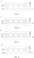
FIG. 6 is a schematic structural diagram of an electronically controlled birefringence passive LCD module when the anti-peep function is turned off according toEmbodiment 1 of the present application; -
FIG. 7 is a schematic structural diagram of the passive LCD module shown inFIG. 6 when the anti-peep function is turned on; -
FIG. 8 is a schematic structural diagram of a vertical nematic passive LCD module when the anti-peep function is turned off according toEmbodiment 1 of the present application; -
FIG. 9 is a schematic structural diagram of the passive LCD module shown inFIG. 8 when the anti-peep function is turned on; -
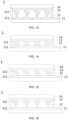
FIG. 10 is a schematic structural diagram of an electronically controlled birefringence passive LCD module when the anti-peep function is turned off according toEmbodiment 2 of the present application; -
FIG. 11 is a schematic structural diagram of the passive LCD module shown inFIG. 10 when the anti-peep function is turned on; -
FIG. 12 is a schematic structural diagram of a vertical nematic passive LCD module when the anti-peep function is turned off according toEmbodiment 2 of the present application; -
FIG. 13 is a schematic structural diagram of the passive LCD module shown inFIG. 12 when the anti-peep function is turned on; -
FIG. 14 is a schematic structural diagram of an electronically controlled birefringence passive LCD module when the anti-peep function is turned off according toEmbodiment 3 of the present application; -
FIG. 15 is a schematic structural diagram of the passive LCD module shown inFIG. 14 when the anti-peep function is turned on; -
FIG. 16 is a schematic structural diagram of a vertical nematic passive LCD module when the anti-peep function is turned off according toEmbodiment 3 of the present application; -
FIG. 17 is a schematic structural diagram of the passive LCD module shown inFIG. 16 when the anti-peep function is turned on; -
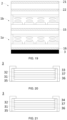
FIG. 18 is a schematic diagram of a stacking structure of a passive LCD module and a color LCD module according to an embodiment of the present application; -
FIG. 19 is a schematic diagram of another stacking structure of a passive LCD module and a color LCD module according to an embodiment of the present application; -
FIG. 20 is a schematic structural diagram of a backlight source including a first light-enhancing film and a second light-enhancing film according to an embodiment of the present application; and -
FIG. 21 is a schematic structural diagram of another backlight source including a first light-enhancing film and a brightness-enhancing film according to an embodiment of the present application. - Reference signs are as follows:
- 1 passive LCD module, 11 first electrode layer, 111 first sub-electrode, 12 liquid crystal layer, 121 liquid crystal molecule, 13 second electrode layer, 131 second sub-electrode electrode, 14 glass substrate, 15 first surface polarizer, 16 first bottom polarizer,
- 2 color LCD module, 2 1 second surface polarizer, 22 second bottom polarizer,
- 3 backlight source, 31 light source, 32 first light-enhancing film, 33 second light-enhancing film, 34 brightness-enhancing film, 35 bracket, 36 reflective film, 37 scattering film,
- 4 compensation film, and
- 5 cover plate.
- In order to make the purpose, technical proposals, and advantages of the present application more clearly understood, the present application will be described in further detail hereinbelow with reference to the accompanying drawings and embodiments. It should be understood that the specific embodiments described here are merely used to explain the present application but not to limit the present application.
- It should be noted that when a component is referred to as being "fixed to" or "disposed on" another component, it may be directly or indirectly disposed on the other component. When a component is referred to as being "connected to" another component, it may be directly or indirectly connected to the other component. The orientation or positional relationship indicated by the terms "upper", "lower", "left", "right", etc. are based on the orientation or positional relationship shown in the drawings, and are merely for the convenience of description and do not indicate or imply the device or elements to which they are referred must have a specific orientation, be constructed and operate in a specific orientation, and therefore cannot be construed as a limitation on the application. The terms "first" and "second" are merely used for the convenience of description and cannot be understood as indicating or implying relative importance or implicitly indicating the quantity of technical features. "A plurality of" means two or more, unless otherwise expressly and specifically limited.
- Reference in the specification of the present application to "one embodiment", "some embodiments", or "an embodiment" means that a particular feature, structure, or characteristic described in connection with the embodiment is included in one or more embodiments of the application. Therefore, the phrases "in one embodiment", "in some embodiments", "in other embodiments", "in another embodiment", etc. appearing in different places in this specification are not necessarily referred to the same embodiment, but rather to "one or more but not all embodiments" unless specifically stated otherwise. Furthermore, the particular features, structures, or characteristics may be combined in any suitable manner in one or more embodiments.
- This embodiment provides an anti-peep display screen, which is applied in products or components with display functions such as LCD TVs, mobile phones, tablets, and vehicle monitors, and has a partitioned anti-peep function.
- As shown in
FIG. 1 , the anti-peep display screen provided by the present application includes apassive LCD module 1 and acolor LCD module 2 stacked along a first direction (direction indicated by X inFIG. 1 ). As shown inFIG. 6 , thepassive LCD module 1 includes afirst electrode layer 11, aliquid crystal layer 12, and asecond electrode layer 13. Thefirst electrode layer 11 includes afirst sub-electrode 111, and thesecond electrode layer 13 includes asecond sub-electrode 131, thefirst sub-electrode 111 and thesecond sub-electrode 131 are opposite to each other and configured to input different voltages to control the light transmission state of thepassive LCD module 1. - The
passive LCD module 1 is a passive display module, and thecolor LCD module 2 is a TFT-LCD. - In the
passive LCD module 1, thefirst electrode layer 11 and thesecond electrode layer 13 are made of a transparent conductive material and are respectively arranged on opposite sides of theliquid crystal layer 12. Thefirst electrode layer 11 may be disposed on a side close to thebacklight source 3, or may also be disposed on a side away from thebacklight source 3. Theliquid crystal layer 12 includesliquid crystal molecules 121 distributed between thefirst electrode layer 11 and thesecond electrode layer 13. In a natural state, theliquid crystal molecules 121 are aligned parallel to thefirst electrode layer 11 and thesecond electrode layer 13. - The
first electrode layer 11 includes afirst sub-electrode 111, and thesecond electrode layer 13 includes asecond sub-electrode 131. By applying a voltage to thefirst electrode layer 11 and/or thesecond electrode layer 13, it is possible to form an electric field in theliquid crystal layer 12, and this electric field acts on theliquid crystal molecules 121, which can change the alignment of theliquid crystal molecules 121, thereby controlling the light transmission state of theliquid crystal layer 12, and enabling the anti-peep function to be turned on or off. - Specifically, as shown in
FIG. 6 , when the voltage difference between thefirst sub-electrode 111 and a correspondingsecond sub-electrode 131 is zero, light incident from both the side and the vertical direction can pass through theliquid crystal layer 12. In this case, the anti-peep function is turned off, and the anti-peep display screen has good visual effects at all viewing angles. As shown inFIG. 7 , when a certain voltage difference is applied between thefirst sub-electrode 111 and the correspondingsecond sub-electrode 131, theliquid crystal molecules 121 can be tilted to a certain angle, that is, theliquid crystal molecules 121 are deflected relative to the liquid crystal surface in a direction perpendicular to the plane of theliquid crystal layer 12. When theliquid crystal molecules 121 are tilted to a certain angle, the light incident from the side is refracted, reflected, or absorbed in theliquid crystal layer 12 and is thus blocked, while the vertical incident light is not affected. In this case, the anti-peep function is turned on, and the content on the anti-peep display becomes blurred or invisible when viewing from the side, while the contents of the anti-peep display remain clearly visible at the vertical viewing angle. - In the anti-peep display screen provided by the present application, the
passive LCD module 1 is utilized in combination with thecolor LCD module 2, and thepassive LCD module 1 includes thefirst electrode layer 11, theliquid crystal layer 12, and thesecond electrode layer 13. Thefirst electrode layer 11 includes thefirst sub-electrode 111, and thesecond electrode layer 13 includes thesecond sub-electrode 131. By regulating the voltage difference between thefirst sub-electrode 111 and thesecond sub-electrode 131, the deflection angle of theliquid crystal molecules 121 in theliquid crystal layer 12 can be controlled, thereby controlling the light transmission state of thepassive LCD module 1 and realizing the on/off of the anti-peep function. During this process, thecolor LCD module 2 functions normally, so that the image display quality of the anti-peep display screen can be ensured while realizing the anti-peep function. In some cases, the number and shape of thefirst sub-electrode 111 and thesecond sub-electrode 131 may also be designed to achieve various forms of the anti-peep function. - In the embodiment provided by the present application, as shown in
FIG. 6 , thefirst electrode layer 11 includes a plurality of independentfirst sub-electrodes 111. The plurality offirst sub-electrodes 111 can be configured to input different voltages to independently control the light transmission state of thepassive LCD module 1 in respective areas where the plurality offirst sub-electrodes 111 are located. - The plurality of
first sub-electrodes 111 are connected to different drive circuits, controlled by the same signal or different signals, and can input the same or different voltages. - Specifically, in some situations, by regulating the input voltages of the plurality of
first sub-electrodes 111, a voltage difference can be formed between the first sub-electrodes 111 (that is, part of the first sub-electrodes 111) and thesecond sub-electrodes 131 in a target area, while the voltage difference between thefirst sub-electrodes 111 and thesecond sub-electrodes 131 outside the target area is zero, so as to individually turn on the anti-peep function of the target area, thereby realizing a partial anti-peep function on the anti-peep display screen. - The above design allows independent control of the light transmission state of the
passive LCD module 1 in the area where the plurality offirst sub-electrodes 111 are located, thereby independently controlling the on/off of the anti-peep function of the anti-peep display screen in the areas where the plurality offirst sub-electrodes 111 are located. Therefore, the independent control of the anti-peep function in multiple areas of the anti-peep display screen can be achieved. - In the embodiment provided by the present application, the
color LCD module 2 includes a plurality of pixel electrodes, and thefirst sub-electrodes 111 are arranged corresponding to at least one of the pixel electrodes. - The
first sub-electrodes 111 are block-shaped, and eachfirst sub-electrode 111 may correspond to one or more pixel electrodes according to the structure anti-peep requirements of the anti-peep display screen. Optionally, in one embodiment, the anti-peep display screen is divided into three areas along the horizontal direction, and thefirst electrode layer 11 is correspondingly configured with three separate first sub-electrodes 111. - With the above design, the structure of the first sub-electrodes 111 matches the resolution of the
color LCD module 2, which aids in improving the display effect of the anti-peep display screen under the anti-peep state. - In the embodiment provided by the present application, the plurality of
first sub-electrodes 111 are arranged in an array, and the spacing between adjacentfirst sub-electrodes 111 is 3 µm-10 µm. - The above design can further improve the matching between the structure of the
first sub-electrodes 111 and thecolor LCD module 2, thereby conducive to improving the display effect of the anti-peep display screen under the anti-peep state. - In the embodiment provided by the present application, as shown in
FIG. 7 , thesecond electrode layer 13 includes a plurality ofsecond sub-electrodes 131, and thesecond sub-electrodes 131 are the same size as the first sub-electrodes 111.The plurality ofsecond sub-electrodes 131 are arranged corresponding to the plurality offirst sub-electrodes 111, respectively. - Specifically, the size, shape, and number of the
second sub-electrodes 131 are the same as those of thefirst sub-electrodes 111. Eachfirst sub-electrode 111 corresponds to asecond sub-electrode 131. Thefirst sub-electrode 111, thesecond sub-electrode 131, and theliquid crystal molecules 121 therebetween together form a functional unit. - The above design aids in improving the accuracy of independent control of each functional unit.
- In the embodiment provided by the present application, when the
first electrode layer 11 includes a plurality offirst sub-electrodes 111 and thesecond electrode layer 13 includes a plurality ofsecond sub-electrodes 131, the control method for the voltage between thefirst sub-electrode 111 and thesecond sub-electrode 131 is not limited. - In some embodiments, the plurality of
first sub-electrodes 111 are connected to different drive circuits, controlled by the same signal or different signals, and configured to input the same or different voltages. The plurality ofsecond sub-electrodes 131 are connected to the same drive circuit, and are controlled by the same signal and configured to input the same voltage. - In some embodiments, the plurality of
first sub-electrodes 111 are connected to different drive circuits, controlled by the same signal or different signals, and configured to input the same or different voltages; the plurality ofsecond sub-electrodes 131 are connected to different drive circuits. The plurality ofsecond sub-electrodes 131 are connected to different drive circuits, controlled by the same signal or different signals, and configured to input the same or different voltages. - In the embodiments provided by the present application, the structure and display mode of the
liquid crystal layer 12 in thepassive LCD module 1 are not limited. - In some embodiments, as shown in
FIGS. 8 and9 , thepassive LCD module 1 is a twisted nematic display module. The pretilt angle of theliquid crystal molecules 121 in the twisted nematic display module is 1°-7°, the twist angle is 80°-100°, and the retardation is 500 nm-1200 nm. - The twisted nematic LCD module has good display performance and the advantages of low energy consumption, low cost and fast response speed. When used in the anti-peep display screen, it can effectively improve product quality and service life.
- In some embodiments, as shown in
FIGS. 6 and 7 , thepassive LCD module 1 is an electronically controlled birefringence display module. The pretilt angle of theliquid crystal molecules 121 in the electronically controlled birefringence display module is 1°-7°, and the retardation is 500 nm-1200 nm. - The electronically controlled birefringent display module has the advantages of small size, light weight, low power consumption, and good light transmission effect. When used in the anti-peep display screen, it can help improve the picture quality.
- In the embodiments provided by the present application, the number of
passive LCD modules 1 is not limited. - In some embodiments, as shown in
FIGS. 1 and 2 , the anti-peep display screen includes apassive LCD module 1. Thepassive LCD module 1 may be a twisted nematic display module or an electronically controlled birefringence display module. - In some embodiments, as shown in
FIGS. 3, 4 and5 , the anti-peep display screen includes twopassive LCD modules 1. The twopassive LCD module 1 may be any of a twisted nematic display module and an electronically controlled birefringence display module. - By combining the plurality of
passive LCD modules 1 and thecolor LCD module 2, the light transmission state can be optimized, and the blocking effect of side incident light in the anti-peep state can be further improved, thereby improving the partitioned anti-peep effect. - It can be understood that the actual number of
passive LCD modules 1 needs to refer to the anti-peep requirements, product appearance requirements, and the like, of the anti-peep display screen, and is not limited here. In addition, when the plurality ofpassive LCD modules 1 are installed in the anti-peep display screen, the structural design of thefirst sub-electrodes 111 of the multiplepassive LCD modules 1 remains consistent. - In the embodiment provided by the present application, when the anti-peep display screen includes a plurality of
passive LCD modules 1, as shown inFIG. 5 , a compensation film 4 is disposed between adjacentpassive LCD modules 1, and the compensation film 4 is a half-wave plate. - Specifically, the compensation film 4 is a 1/2 half-wave plate.
- The compensation film 4 is configured to adjust the propagation direction of light and reduce the polarization rotation effect of light in the
liquid crystal layer 12 by adjusting the propagation speed of light, thereby reducing the loss of light to increase the brightness of the module and improve the image quality of the anti-peep display screen. - In the embodiment provided by the present application, in order to further improve the image quality, as shown in
FIGS. 2, 4 and5 , a compensation film 4 is disposed between the adjacentpassive LCD module 1 and thecolor LCD module 2. - It can be understood that in some embodiments, in order to reduce the cost of the anti-peep display screen, the compensation film 4 structure may be omitted.
- In the embodiments provided by the present application, the anti-peep display screen also includes a
backlight source 3, and the location of thebacklight source 3 is not limited. - In some embodiments, as shown in
FIG. 18 , thebacklight source 3 is disposed on a side of thepassive LCD module 1 away from thecolor LCD module 2 along the first direction. - In some embodiments, as shown in
FIG. 19 , thebacklight source 3 is disposed on a side of thecolor LCD module 2 away from thepassive LCD module 1. - In the embodiments provided by the present application, the structure of the
backlight source 3 is also not limited. - In some embodiments, as shown in
FIG. 20 , thebacklight source 3 includes a light source 31, a first light-enhancingfilm 32, and a second light-enhancingfilm 33 disposed along the first direction, an angle between the optical axes of the first light-enhancing film32 and the second light-enhancingfilm 33 is 0°-90°. - The light source 31 may be a direct light source or an edge-type light source, and the light source 31 includes a light emitting component and a light guiding plate.
- The angle between the first light-enhancing
film 32 and the second light-enhancingfilm 33 is designed according to the actual situation. Optionally, in one embodiment, the angle between the first light-enhancingfilm 32 and the horizontal line is designed to be 90°-110°, and the angle between the second light-enhancingfilm 33 and the horizontal line is designed to be 10°-30°. - The light-enhancing film is disposed in front of the light source 31, which can diffuse and evenly distribute light, and focus the light in the front direction, thereby improving the brightness and uniformity of the light emitted by the
backlight source 3. - With the above design, the first light-enhancing
film 32 and the second light-enhancingfilm 33 are stacked and cooperate with each other, which further improves the diffusion effect and brightness of thebacklight source 3, thereby achieving higher brightness, better uniformity and wider viewing angle. This enables the anti-peep display to achieve a better display effect. - In some embodiments, as shown in
FIG. 21 , thebacklight source 3 includes a light source 31, a first light-enhancingfilm 32 and a brightness-enhancingfilm 34 disposed along a first direction, and an angle between the optical axes of the first light-enhancingfilm 32 and the brightness-enhancingfilm 34 is 0°-90°. - The brightness-enhancing
film 34 is disposed in front of the light source 31, which has certain reflection control capabilities, and can be used to increase the brightness and contrast of thebacklight source 3. - The angle between the first light-enhancing
film 32 and the brightness-enhancingfilm 34 is designed according to the actual situation. When the angle between the optical axes of the first light-enhancingfilm 32 and the brightness-enhancingfilm 34 is 0°, that is, when the optical axes of the two film layers are designed to be horizontal, an optimum enhancing effect can be obtained. - With the above design, the first light-enhancing
film 32 and the second light-enhancingfilm 33 are stacked and cooperate with each other, which can improve the diffusion effect and brightness of thebacklight source 3 and increase the contrast, thereby improving the clarity and vibrance of the display image of the anti-peep display screen. - It should be noted that the
backlight source 3 also includes abracket 35, areflective film 36, ascattering film 37 and so on, which can be referred to the existing technology and will not be repeated here. - In the embodiment provided by the present application, the
passive LCD module 1 and thecolor LCD module 2 also include a polarizer structure, and the arrangement of the polarizer is not limited. - In some embodiments, in order to reduce the thickness and manufacturing cost of the anti-peep display screen, adjacent display modules may share the same polarizer.
- In the embodiment shown in
FIG. 18 , the anti-peep display screen includes a firstpassive LCD module 1a, a secondpassive LCD module 1b, acolor LCD module 2, and abacklight source 3 arranged in sequence. The firstpassive LCD module 1a includes afirst surface polarizer 15 and afirst bottom polarizer 16, and thecolor LCD module 2 includes asecond surface polarizer 21 and asecond bottom polarizer 22. Thefirst bottom polarizer 16 is also used as the surface polarizer of the secondpassive LCD module 1b, and thesecond surface polarizer 21 is also used as the bottom polarizer of the secondpassive LCD module 1b. - In the embodiment shown in
FIG. 19 , the anti-peep display screen includes abacklight source 3, a firstpassive LCD module 1a, a secondpassive LCD module 1b, and acolor LCD module 2 arranged in sequence. The firstpassive LCD module 1a includes afirst surface polarizer 15 and afirst bottom polarizer 16, and thecolor LCD module 2 includes asecond surface polarizer 21 and asecond bottom polarizer 22. Thefirst surface polarizer 15 is also used as the bottom polarizer of the secondpassive LCD module 1b , and thesecond bottom polarizer 22 is also used as the surface polarizer of the secondpassive LCD module 1b. - In some embodiments, the thickness requirements for the anti-peep display screen are low. In order to reduce manufacturing difficulty, independent surface polarizers and bottom polarizers can be configured for each group of the
passive LCD module 1 andcolor LCD module 2, which can refer to the existing technology and will not be repeated here. - In the embodiment provided by the present application, as shown in
FIG. 6 , thepassive LCD module 1 is also equipped with aglass substrate 14 for arranging the electrode layer structure. - In the embodiment provided by the present application, as shown in
FIG. 1 , the anti-peep display screen also includes acover plate 5, and a special coating or functional film is applied on the surface of thecover plate 5. The special coatings and functional films may be one or a combination of an anti-glare, anti-reflective, and anti-fingerprint film. - In summary, the anti-peep display screen provided by the present application combines the
passive LCD module 1 and thecolor LCD module 2. By controlling the light transmission state of thepassive LCD module 1, the on/off of the anti-peep function of the anti-peep display screen can be achieved. By improving the structure of thefirst electrode layer 11 and thesecond electrode layer 13 in thepassive LCD module 1, thefirst electrode layer 11 is configured with a plurality of independentfirst sub-electrodes 111, and thesecond electrode layer 13 is configured with a plurality of independentsecond sub-electrodes 131, this can realize the partial anti-peep effect and multi-area independent control of the anti-peep function in the anti-peep display screen. - This embodiment provides an anti-peep display screen. The difference from the proposal provided in
Embodiment 1 is that: as shown inFIGS. 10 to 13 , thefirst electrode layer 11 in thepassive LCD module 1 includes a plurality offirst sub-electrodes 111 and thesecond electrode layer 13 include onesecond sub-electrode 131, and a projection of thesecond sub-electrode 131 on thefirst electrode layer 11 covers the plurality offirst sub-electrodes 111. -
FIGS. 10 and 11 show an electronically controlled birefringencepassive LCD module 1.FIGS. 12 and13 show a vertical nematicpassive LCD module 1. - In practical applications, by individually regulating the input voltages of the plurality of
first sub-electrodes 111 in thefirst electrode layer 11, a partitioned adjustment of the anti-peep function is achieved. - With the above design, the
second electrode layer 13 has an integrated-surface structure, so that the processing and manufacturing difficulty of the anti-peep display screen can be reduced. - This embodiment provides an anti-peep display screen. The difference from the proposal provided in
Embodiment 1 is that: as shown inFIGS. 14 to 17 , thefirst electrode layer 11 in thepassive LCD module 1 includes afirst sub-electrode 111, and thesecond electrode layer 13 includes a second sub-electrode 131 corresponding to thefirst sub-electrode 111. -
FIGS. 14 and 15 show an electronically controlled birefringencepassive LCD module 1.FIGS. 16 and17 show a vertical nematicpassive LCD module 1. - In some small-sized products, both the
first sub-electrode 111 and thesecond sub-electrode 131 may be designed as an integrated structure, and adjusting the voltage difference between thefirst sub-electrode 111 and thesecond sub-electrode 131 allows the screen to switch between anti-peep and non-anti-peep modes. - This embodiment provides a vehicle-mounted display device, including any one of the anti-peep display screens in
Embodiment 1 toEmbodiment 3. - The vehicle-mounted display device also includes structures such as a housing, a power supply, a fixed bracket.
- The vehicle-mounted display device provided by the present application improves the structure of the anti-peep display screen. On the one hand, by combining a
passive LCD module 1 with acolor LCD module 2 and utilizing thepassive LCD module 1 to turn on or off the anti-peep function, the image display quality of the vehicle-mounted display device can be effectively improved; on the other hand, in some situations, the structure of the sub-electrodes in thepassive LCD module 1 is allowed to be customized to realize various forms of anti-peep function. - For example, in the anti-peep display screen provided in
Embodiment 2, the anti-peep function of multiple areas can be turned on or off independently, so that it can be applied in a variety of scenarios, having a variety of using methods and high security. - For example, the above-mentioned vehicle-mounted display device may be configured at the passenger seat. If it is allowed by the traffic conditions, the anti-peep function of the display screen can be turned off and the on-board display device can be switched to a sharing mode so that the driver and passengers can see different content respectively; if it is not allowed by the traffic conditions, the anti-peep function of the area of the display screen close to the driver's side can be turned on, and the anti-peep function of other areas of the display screen can be turned off, so that the on-board display device can be switched to the anti-peep mode so that passengers can browse multimedia content without affecting the driving safety of the driver, thereby providing entertainment services to the front-seat passenger.
- This embodiment provides a vehicle, including the vehicle-mounted display device in Embodiment 4.
- The vehicle provided by the present application can provide more entertainment services to the front-seat passenger without affecting the driving safety of the driver by designing a vehicle-mounted display module with anti-peep function.
- The above-described embodiments are only used to illustrate the technical proposals of the present application, but not to limit them. Although the present application has been described in detail with reference to the foregoing embodiments, those of ordinary skill in the art should understand that the technical proposals described in the foregoing embodiments can be modified, or some of the technical features can be replaced by their equivalents; and these modifications or substitutions do not cause the essence of the corresponding technical proposals to deviate from the spirit and scope of the technical proposals in the embodiments of the present application, and should fall within the protection scope of the present application.
Claims (14)
- An anti-peep display screen, comprising:a passive liquid crystal display module and a color liquid crystal display module stacked along a first direction;wherein, the passive liquid crystal display module comprises a first electrode layer, a liquid crystal layer and a second electrode layer, the first electrode layer comprises a first sub-electrode, the second electrode layer comprises a second sub-electrode, and the first sub-electrode is opposite to the second sub-electrode and configured to input different voltages, so as to control a light transmission state of the passive liquid crystal display module.
- The anti-peep display screen according to claim 1, wherein the first electrode layer comprises a plurality of independent first sub-electrodes, and the plurality of first sub-electrodes is configured to input different voltages to independently control the light transmission state of the passive liquid crystal display module in areas where the plurality of first sub-electrodes are located.
- The anti-peep display screen according to claim 2, wherein the second electrode layer comprises a plurality of second sub-electrodes, each of the plurality of second sub-electrodes has the same size as each of the plurality of first sub-electrodes, and the plurality of second sub-electrodes are arranged corresponding to the plurality of first sub-electrodes, respectively.
- The anti-peep display screen according to claim 2, wherein the number of the second sub-electrode in the second electrode layer is one, and a projection of the second sub-electrode on the first electrode layer covers the plurality of first sub-electrodes.
- The anti-peep display screen according to claim 1, wherein the first electrode layer comprises one first sub-electrode, and the second electrode layer comprises one second sub-electrode opposite to the first sub-electrode.
- The anti-peep display screen according to any of claims 1 to 5, wherein the number of the passive liquid crystal display module in the anti-peep display screen is one or two.
- The anti-peep display screen according to claim 6, wherein the anti-peep display screen comprises two passive liquid crystal display modules, and a compensation film which is a half-wave plate is disposed between the two passive liquid crystal display modules.
- The anti-peep display screen according to any of claims 1 to 5, wherein the passive liquid crystal display module is a twisted nematic display module or an electronically controlled birefringence display module.
- The anti-peep display screen according to claim 8, wherein a pretilt angle of liquid crystal molecules in the twisted nematic display module is 1°-7°, a twist angle thereof is 80°-100°, and a retardation is 500 nm-1200 nm;
a pretilt angle of liquid crystal molecules in the electronically controlled birefringence display module is 1°-7°, and a retardation is 500 nm-1200 nm. - The anti-peep display screen according to any of claims 1 to 5, wherein the color liquid crystal display module comprises a plurality of pixel electrodes, and the first sub-electrode is arranged corresponding to at least one of the pixel electrodes.
- The anti-peep display screen according to any of claims 1 to 5, wherein a compensation film is provided between the passive liquid crystal display module and adjacent color liquid crystal display module, and the compensation film is a half-wave plate.
- The anti-peep display screen according to any of claims 1 to 5, wherein the anti-peep display screen further comprises a backlight source, and the backlight source comprises a light source, a first light-enhancing film, and a second light-enhancing film disposed along the first direction, an angle between optical axes of the first light-enhancing film and the second light-enhancing film is 0°-90°;
alternatively,
the backlight source comprises a light source, a first light-enhancing film, and a brightness-enhancing film disposed along the first direction, and an angle between optical axes of the first light-enhancing film and the brightness-enhancing film is 0°-90°. - A vehicle-mounted display device, comprising the anti-peep display screen according to any of claims 1 to 12.
- A vehicle, comprising the vehicle-mounted display device according to claim 13.
Applications Claiming Priority (1)
| Application Number | Priority Date | Filing Date | Title |
|---|---|---|---|
| CN202311034766.7A CN117031799A (en) | 2023-08-16 | 2023-08-16 | Peep-proof display screen, vehicle-mounted display device and vehicle |
Publications (3)
| Publication Number | Publication Date |
|---|---|
| EP4509907A1 true EP4509907A1 (en) | 2025-02-19 |
| EP4509907B1 EP4509907B1 (en) | 2026-02-11 |
| EP4509907C0 EP4509907C0 (en) | 2026-02-11 |
Family
ID=88627747
Family Applications (1)
| Application Number | Title | Priority Date | Filing Date |
|---|---|---|---|
| EP23214888.2A Active EP4509907B1 (en) | 2023-08-16 | 2023-12-07 | Anti-peep display screen, vehicle-mounted display device and vehicle |
Country Status (3)
| Country | Link |
|---|---|
| US (1) | US12436418B2 (en) |
| EP (1) | EP4509907B1 (en) |
| CN (1) | CN117031799A (en) |
Citations (5)
| Publication number | Priority date | Publication date | Assignee | Title |
|---|---|---|---|---|
| KR20100050632A (en) * | 2008-11-06 | 2010-05-14 | 주식회사 엘엠에스 | Prism sheet, backlight unit and liquid crystal display including the same |
| US8045097B2 (en) * | 2006-08-09 | 2011-10-25 | Sharp Kabushiki Kaisha | Liquid crystal display device and viewing angle control module |
| US20220155631A1 (en) * | 2021-09-30 | 2022-05-19 | Shanghai Tianma Micro-electronics Co., Ltd. | Display module, method for driving the same, display apparatus, and vehicle |
| US20220229320A1 (en) * | 2021-12-31 | 2022-07-21 | Shanghai Avic Optoelectronics Co., Ltd. | Switchable viewing angle display module and vehicle |
| US20230176405A1 (en) * | 2021-12-02 | 2023-06-08 | Coretronic Corporation | Display apparatus and method of driving the same |
Family Cites Families (13)
| Publication number | Priority date | Publication date | Assignee | Title |
|---|---|---|---|---|
| KR100502103B1 (en) * | 1998-03-12 | 2005-11-11 | 삼성전자주식회사 | Liquid crystal display |
| JP2006330164A (en) * | 2005-05-24 | 2006-12-07 | Casio Comput Co Ltd | Liquid crystal display |
| CN204790254U (en) | 2015-05-05 | 2015-11-18 | 上海冠显光电科技有限公司 | Changeable peep -proof liquid crystal disply device of separated regions control |
| CN109219770B (en) * | 2016-06-20 | 2022-03-22 | 大日本印刷株式会社 | Light control film, driving method of light control film, light control member, vehicle |
| US10782545B2 (en) * | 2018-05-16 | 2020-09-22 | Sharp Kabushiki Kaisha | Liquid crystal private device |
| CN111796438B (en) * | 2019-04-09 | 2024-07-26 | 中强光电股份有限公司 | Viewing angle switching module and display device |
| JP7395328B2 (en) * | 2019-11-14 | 2023-12-11 | 株式会社ジャパンディスプレイ | Vehicle display device |
| CN111323946B (en) * | 2020-03-19 | 2022-09-23 | 昆山龙腾光电股份有限公司 | Liquid crystal display device and driving method thereof |
| CN114049866A (en) | 2021-11-26 | 2022-02-15 | 福州京东方光电科技有限公司 | Liquid crystal display device, control method and apparatus, storage medium, and electronic device |
| CN219065932U (en) * | 2023-02-06 | 2023-05-23 | 中强光电股份有限公司 | display device |
| US11977286B2 (en) * | 2022-02-09 | 2024-05-07 | Reald Spark, Llc | Observer-tracked privacy display |
| CN115616820B (en) | 2022-06-14 | 2023-10-20 | 荣耀终端有限公司 | Peep-proof display screen, electronic equipment and peep-proof method |
| CN220543234U (en) * | 2023-08-16 | 2024-02-27 | 精电(河源)显示技术有限公司 | Anti-peep display screens, vehicle-mounted display devices and vehicles |
-
2023
- 2023-08-16 CN CN202311034766.7A patent/CN117031799A/en active Pending
- 2023-12-07 EP EP23214888.2A patent/EP4509907B1/en active Active
- 2023-12-14 US US18/539,806 patent/US12436418B2/en active Active
Patent Citations (5)
| Publication number | Priority date | Publication date | Assignee | Title |
|---|---|---|---|---|
| US8045097B2 (en) * | 2006-08-09 | 2011-10-25 | Sharp Kabushiki Kaisha | Liquid crystal display device and viewing angle control module |
| KR20100050632A (en) * | 2008-11-06 | 2010-05-14 | 주식회사 엘엠에스 | Prism sheet, backlight unit and liquid crystal display including the same |
| US20220155631A1 (en) * | 2021-09-30 | 2022-05-19 | Shanghai Tianma Micro-electronics Co., Ltd. | Display module, method for driving the same, display apparatus, and vehicle |
| US20230176405A1 (en) * | 2021-12-02 | 2023-06-08 | Coretronic Corporation | Display apparatus and method of driving the same |
| US20220229320A1 (en) * | 2021-12-31 | 2022-07-21 | Shanghai Avic Optoelectronics Co., Ltd. | Switchable viewing angle display module and vehicle |
Also Published As
| Publication number | Publication date |
|---|---|
| US12436418B2 (en) | 2025-10-07 |
| EP4509907B1 (en) | 2026-02-11 |
| EP4509907C0 (en) | 2026-02-11 |
| US20250060621A1 (en) | 2025-02-20 |
| CN117031799A (en) | 2023-11-10 |
Similar Documents
| Publication | Publication Date | Title |
|---|---|---|
| US10725228B2 (en) | Electronic device display with switchable film structures | |
| TWI902076B (en) | Reflective optical stack for privacy display | |
| EP1589366B1 (en) | Display | |
| TW202332973A (en) | Display device with uniform off-axis luminance reduction | |
| CN100472280C (en) | Optical element and display device using same | |
| US7760301B2 (en) | Liquid crystal device and electronic apparatus | |
| WO2016195786A1 (en) | Electronic device display with switchable film structures | |
| US9568771B2 (en) | Liquid crystal device, electronic device and projector with maximum-light-intensity direction inclined from the direction normal to the substrates | |
| US10663798B2 (en) | Liquid crystal display panel comprising a liquid crystal prism and a reflective prism disposed between first and second substrates and driving method thereof, and display device | |
| CN215264292U (en) | Liquid crystal display panel and display device | |
| KR20090058992A (en) | Multi-Visual Display | |
| US20090015732A1 (en) | Display apparatus | |
| WO1994022045A1 (en) | Liquid crystal display with enhanced luminance and uniform off-axis luminance characteristics | |
| JP2008299280A (en) | Display and viewing angle control device used therefor | |
| CN220543234U (en) | Anti-peep display screens, vehicle-mounted display devices and vehicles | |
| US12436418B2 (en) | Anti-peep display screen, vehicle-mounted display device and vehicle | |
| CN118786383A (en) | Privacy display for observer tracking | |
| CN219758625U (en) | Liquid crystal display module and display device | |
| US20240427180A1 (en) | Display device | |
| US12164138B2 (en) | Backlight module including switchable diffusion sheet and display device including the same | |
| US20250370300A1 (en) | Display device | |
| JP2008102459A (en) | Liquid crystal display | |
| CN118647927A (en) | Display device with uniform off-axis brightness reduction | |
| WO2007110998A1 (en) | Liquid crystal display and television receiver |
Legal Events
| Date | Code | Title | Description |
|---|---|---|---|
| PUAI | Public reference made under article 153(3) epc to a published international application that has entered the european phase |
Free format text: ORIGINAL CODE: 0009012 |
|
| STAA | Information on the status of an ep patent application or granted ep patent |
Free format text: STATUS: REQUEST FOR EXAMINATION WAS MADE |
|
| 17P | Request for examination filed |
Effective date: 20231207 |
|
| AK | Designated contracting states |
Kind code of ref document: A1 Designated state(s): AL AT BE BG CH CY CZ DE DK EE ES FI FR GB GR HR HU IE IS IT LI LT LU LV MC ME MK MT NL NO PL PT RO RS SE SI SK SM TR |
|
| GRAP | Despatch of communication of intention to grant a patent |
Free format text: ORIGINAL CODE: EPIDOSNIGR1 |
|
| STAA | Information on the status of an ep patent application or granted ep patent |
Free format text: STATUS: GRANT OF PATENT IS INTENDED |
|
| RIC1 | Information provided on ipc code assigned before grant |
Ipc: G02F 1/13 20060101AFI20250715BHEP Ipc: G02F 1/1343 20060101ALI20250715BHEP Ipc: G02F 1/1347 20060101ALI20250715BHEP Ipc: G06F 21/84 20130101ALI20250715BHEP Ipc: B60K 35/22 20240101ALI20250715BHEP Ipc: B60K 35/00 20240101ALI20250715BHEP |
|
| INTG | Intention to grant announced |
Effective date: 20250801 |
|
| GRAS | Grant fee paid |
Free format text: ORIGINAL CODE: EPIDOSNIGR3 |
|
| GRAA | (expected) grant |
Free format text: ORIGINAL CODE: 0009210 |
|
| STAA | Information on the status of an ep patent application or granted ep patent |
Free format text: STATUS: THE PATENT HAS BEEN GRANTED |
|
| AK | Designated contracting states |
Kind code of ref document: B1 Designated state(s): AL AT BE BG CH CY CZ DE DK EE ES FI FR GB GR HR HU IE IS IT LI LT LU LV MC ME MK MT NL NO PL PT RO RS SE SI SK SM TR |
|
| REG | Reference to a national code |
Ref country code: CH Ref legal event code: F10 Free format text: ST27 STATUS EVENT CODE: U-0-0-F10-F00 (AS PROVIDED BY THE NATIONAL OFFICE) Effective date: 20260211 Ref country code: GB Ref legal event code: FG4D |
|
| REG | Reference to a national code |
Ref country code: CH Ref legal event code: R17 Free format text: ST27 STATUS EVENT CODE: U-0-0-R10-R17 (AS PROVIDED BY THE NATIONAL OFFICE) Effective date: 20260302 |
|
| REG | Reference to a national code |
Ref country code: DE Ref legal event code: R096 Ref document number: 602023011857 Country of ref document: DE |
|
| REG | Reference to a national code |
Ref country code: IE Ref legal event code: FG4D |
|
| U01 | Request for unitary effect filed |
Effective date: 20260305 |
|
| U07 | Unitary effect registered |
Designated state(s): AT BE BG DE DK EE FI FR IT LT LU LV MT NL PT RO SE SI Effective date: 20260311 |