EP4509877A1 - Touchless lavatory optical time of flight proximity sensor - Google Patents
Touchless lavatory optical time of flight proximity sensor Download PDFInfo
- Publication number
- EP4509877A1 EP4509877A1 EP24194340.6A EP24194340A EP4509877A1 EP 4509877 A1 EP4509877 A1 EP 4509877A1 EP 24194340 A EP24194340 A EP 24194340A EP 4509877 A1 EP4509877 A1 EP 4509877A1
- Authority
- EP
- European Patent Office
- Prior art keywords
- time
- microcontroller
- flight
- photon
- command
- Prior art date
- Legal status (The legal status is an assumption and is not a legal conclusion. Google has not performed a legal analysis and makes no representation as to the accuracy of the status listed.)
- Pending
Links
Images

Classifications
-
- G—PHYSICS
- G01—MEASURING; TESTING
- G01S—RADIO DIRECTION-FINDING; RADIO NAVIGATION; DETERMINING DISTANCE OR VELOCITY BY USE OF RADIO WAVES; LOCATING OR PRESENCE-DETECTING BY USE OF THE REFLECTION OR RERADIATION OF RADIO WAVES; ANALOGOUS ARRANGEMENTS USING OTHER WAVES
- G01S17/00—Systems using the reflection or reradiation of electromagnetic waves other than radio waves, e.g. lidar systems
- G01S17/02—Systems using the reflection of electromagnetic waves other than radio waves
- G01S17/04—Systems determining the presence of a target
-
- E—FIXED CONSTRUCTIONS
- E03—WATER SUPPLY; SEWERAGE
- E03C—DOMESTIC PLUMBING INSTALLATIONS FOR FRESH WATER OR WASTE WATER; SINKS
- E03C1/00—Domestic plumbing installations for fresh water or waste water; Sinks
- E03C1/02—Plumbing installations for fresh water
- E03C1/05—Arrangements of devices on wash-basins, baths, sinks, or the like for remote control of taps
- E03C1/055—Electrical control devices, e.g. with push buttons, control panels or the like
- E03C1/057—Electrical control devices, e.g. with push buttons, control panels or the like touchless, i.e. using sensors
-
- A—HUMAN NECESSITIES
- A47—FURNITURE; DOMESTIC ARTICLES OR APPLIANCES; COFFEE MILLS; SPICE MILLS; SUCTION CLEANERS IN GENERAL
- A47K—SANITARY EQUIPMENT; ACCESSORIES THEREFOR, e.g. TOILET ACCESSORIES
- A47K5/00—Holders or dispensers for soap, toothpaste or the like
- A47K5/06—Dispensers for soap
- A47K5/12—Dispensers for soap for liquid or pasty soap
- A47K5/1217—Electrical control means for the dispensing mechanism
-
- B—PERFORMING OPERATIONS; TRANSPORTING
- B64—AIRCRAFT; AVIATION; COSMONAUTICS
- B64D—EQUIPMENT FOR FITTING IN OR TO AIRCRAFT; FLIGHT SUITS; PARACHUTES; ARRANGEMENT OR MOUNTING OF POWER PLANTS OR PROPULSION TRANSMISSIONS IN AIRCRAFT
- B64D11/00—Passenger or crew accommodation; Flight-deck installations not otherwise provided for
- B64D11/02—Toilet fittings
-
- G—PHYSICS
- G01—MEASURING; TESTING
- G01S—RADIO DIRECTION-FINDING; RADIO NAVIGATION; DETERMINING DISTANCE OR VELOCITY BY USE OF RADIO WAVES; LOCATING OR PRESENCE-DETECTING BY USE OF THE REFLECTION OR RERADIATION OF RADIO WAVES; ANALOGOUS ARRANGEMENTS USING OTHER WAVES
- G01S17/00—Systems using the reflection or reradiation of electromagnetic waves other than radio waves, e.g. lidar systems
- G01S17/02—Systems using the reflection of electromagnetic waves other than radio waves
- G01S17/06—Systems determining position data of a target
- G01S17/08—Systems determining position data of a target for measuring distance only
-
- G—PHYSICS
- G01—MEASURING; TESTING
- G01S—RADIO DIRECTION-FINDING; RADIO NAVIGATION; DETERMINING DISTANCE OR VELOCITY BY USE OF RADIO WAVES; LOCATING OR PRESENCE-DETECTING BY USE OF THE REFLECTION OR RERADIATION OF RADIO WAVES; ANALOGOUS ARRANGEMENTS USING OTHER WAVES
- G01S17/00—Systems using the reflection or reradiation of electromagnetic waves other than radio waves, e.g. lidar systems
- G01S17/02—Systems using the reflection of electromagnetic waves other than radio waves
- G01S17/06—Systems determining position data of a target
- G01S17/08—Systems determining position data of a target for measuring distance only
- G01S17/10—Systems determining position data of a target for measuring distance only using transmission of interrupted, pulse-modulated waves
-
- G—PHYSICS
- G01—MEASURING; TESTING
- G01S—RADIO DIRECTION-FINDING; RADIO NAVIGATION; DETERMINING DISTANCE OR VELOCITY BY USE OF RADIO WAVES; LOCATING OR PRESENCE-DETECTING BY USE OF THE REFLECTION OR RERADIATION OF RADIO WAVES; ANALOGOUS ARRANGEMENTS USING OTHER WAVES
- G01S17/00—Systems using the reflection or reradiation of electromagnetic waves other than radio waves, e.g. lidar systems
- G01S17/88—Lidar systems specially adapted for specific applications
-
- G—PHYSICS
- G01—MEASURING; TESTING
- G01V—GEOPHYSICS; GRAVITATIONAL MEASUREMENTS; DETECTING MASSES OR OBJECTS; TAGS
- G01V8/00—Prospecting or detecting by optical means
- G01V8/10—Detecting, e.g. by using light barriers
- G01V8/12—Detecting, e.g. by using light barriers using one transmitter and one receiver
- G01V8/14—Detecting, e.g. by using light barriers using one transmitter and one receiver using reflectors
Definitions
- the present disclosure relates generally to improved sensor systems and methods and, more particularly, to improved sensor systems and methods for an aircraft lavatory.
- a lavatory of an aircraft includes many surfaces that require activation, such as a faucet, a soap dispenser, a waste flap, a toilet flush, a toilet seat, and a toilet, among others.
- Typical lavatory systems have manually activated switches for activation of these surfaces.
- infrared technology has been used to activate devices such as a touchless faucet or a touchless soap dispenser, among others.
- a conventional infrared touchless soap dispenser and a touchless water faucet, placed in close proximity within an aircraft lavatory sink are typically susceptible to false activation and low performance due to the color, size, and reflectance dependency of the target object.
- a time-of-flight controlled touchless device includes a time-of-flight sensor and a microcontroller in operable communication with the time-of-flight sensor.
- the microcontroller is configured to: command the time-of-flight sensor to emit a photon in a predefined direction, wherein the time-of-flight sensor includes an infrared laser that emits the photon; command the time-of-flight sensor to receive the photon reflected off a surface; determine a target object's distance based on a time-of-flight between emitting the photon and receiving the photon; compare the target object's distance to a predefined range; and, responsive to the target object's distance being within the predefined range, command an actuator on the dispensing valve to activate to dispense a liquid.
- the microcontroller is further configured to: responsive to the target object's distance being outside the predefined range, command the actuator on the dispensing valve to deactivate to prevent the liquid from dispensing.
- the time-of-flight controlled touchless device further includes the dispensing valve.
- the actuator on the dispensing valve is configured to: activate responsive to receiving an activation command from the microcontroller; and deactivate responsive to receiving a deactivation command from the microcontroller.
- the dispensing valve dispenses at least one of water or soap.
- the time-of-flight sensor includes an infrared emitter configured to emit the photon in the predefined direction responsive to receiving a command from the microcontroller. In various embodiments, the time-of-flight sensor comprises an infrared receiver configured to receive the photon reflected off the surface responsive to receiving a command from the microcontroller. In various embodiments, the time-of-flight controlled touchless device further includes a manual override configured to manually activate the actuator on the dispensing valve to dispense the liquid. In various embodiments, the microcontroller is configured to receive electrical power and distribute the electrical power to the time-of-flight sensor and the dispensing valve.
- the aircraft lavatory includes a time-of-flight controlled touchless device.
- the time-of-flight controlled touchless device includes a time-of-flight sensor and a microcontroller in operable communication with the time-of-flight sensor.
- the microcontroller is configured to: command the time-of-flight sensor to emit a photon in a predefined direction, wherein the time-of-flight sensor includes an infrared laser that emits the photon; command the time-of-flight sensor to receive the photon reflected off a surface; determine a target object's distance based on a time-of-flight between emitting the photon and receiving the photon; compare the target object's distance to a predefined range; and, responsive to the target object's distance being within the predefined range, command an actuator on a dispensing valve to activate to dispense a liquid.
- the microcontroller is further configured to: responsive to the target object's distance being outside the predefined range, command the actuator on the dispensing valve to deactivate to prevent the liquid from dispensing.
- the time-of-flight controlled touchless device further includes the dispensing valve.
- the actuator on the dispensing valve is configured to: activate responsive to receiving an activation command from the microcontroller; and deactivate responsive to receiving a deactivation command from the microcontroller.
- the dispensing valve dispenses at least one of water or soap.
- the time-of-flight sensor includes an infrared emitter configured to emit the photon in the predefined direction responsive to receiving a command from the microcontroller. In various embodiments, the time-of-flight sensor includes an infrared receiver configured to receive the photon reflected off the surface responsive to receiving a command from the microcontroller. In various embodiments, the time-of-flight controlled touchless device further includes a manual override configured to manually activate the actuator on the dispensing valve to dispense the liquid. In various embodiments, the microcontroller is configured to receive electrical power and distribute the electrical power to the time-of-flight sensor and the dispensing valve.
- the method includes commanding, by a microcontroller, a time-of-flight sensor to emit a photon in a predefined direction, wherein the time-of-flight sensor includes an infrared laser that emits the photon; commanding, by the microcontroller, the time-of-flight sensor to receive the photon reflected off a surface; determining, by the microcontroller, a target object's distance based on a time-of-flight between emitting the photon and receiving the photon; comparing, by the microcontroller, the target object's distance to a predefined range; and, responsive to the target object's distance being within the predefined range, commanding, by the microcontroller, an actuator on a dispensing valve to activate to dispense a liquid.
- the method further includes, responsive to the target object's distance being outside the predefined range, commanding, by the microcontroller, the actuator on the dispensing valve to deactivate to prevent the liquid from dispensing.
- the time-of-flight sensor includes an infrared emitter to emit the photon in the predefined direction and an infrared receiver to receive the photon reflected off the surface.
- the predefined direction is an area where the liquid will be dispensed.
- references to "a,” “an,” or “the” may include one or more than one and that reference to an item in the singular may also include the item in the plural. Further, all ranges may include upper and lower values and all ranges and ratio limits disclosed herein may be combined.
- a lavatory of an aircraft includes many surfaces that require activation, such as a faucet, a soap dispenser, a waste flap, a toilet flush, a toilet seat, and a toilet, among others.
- Infrared technology has been used to activate devices such as a touchless faucet or a touchless soap dispenser, among others.
- a conventional infrared touchless soap dispenser and a touchless water faucet placed in close proximity within an aircraft lavatory sink, are typically susceptible to false activation and low performance due to the color, size, and reflectance dependency of the target object.
- a touchless device for a lavatory of an aircraft that utilizes a time-of-flight (ToF) to detect the target object's distance and activate the touchless device in response to the target object being within an area of defined activation range.
- an infrared emitter i.e. an infrared laser
- a microcontroller within the touchless device
- an infrared receiver within the touchless device and under command of the microcontroller, is configured to receive the photon after the photon has reflected off a surface, i.e. a sink or a target object, among others.
- the microcontroller determines a time-of-flight to detect the target object's distance from the infrared emitter and the infrared receiver. In various embodiments, if the target object's distance is within a predefined range, then the microcontroller is configured to send a command to an actuator on a dispensing valve. In various embodiments, in response to receiving the command, the actuator on the dispensing valve is configured to activate to allow a liquid, such as water or soap, among others, or to actuate a flushometer or the like to be dispensed.
- a liquid such as water or soap, among others
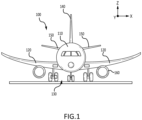
- the aircraft 100 comprises a fuselage 110, wings 120 extending outward from the fuselage 110, a landing gear system 130, a vertical stabilizer 140, horizontal stabilizers 150, and engines 160.
- fuselage 110 defines an aircraft cabin therein.
- passengers may board the aircraft 100 and sit within the aircraft cabin during travel.
- the aircraft cabin includes at least one lavatory disposed therein, as described further herein.
- aircraft lavatories may have limited space within the aircraft cabin in order to maximize passenger space and/or limit drag of the aircraft 100 during flight.
- a time-of-flight enable touchless device within the lavatory of the aircraft 100 provides for the touchless device to operate reliably with an optimal range of interest for object detection.
- a time-of-flight ranging may be independent of color, size, and reflectance of the target object, which may aid in activation of the touchless device only when intended.
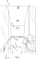
- the lavatory 200 includes a plurality of sensors 210 (e.g., a sensors 211, 212, 213, 214, 215, 216).
- each sensor in the plurality of sensors 210 may be disposed proximate a device which the respective sensor is configured to activate.
- sensor 211 is disposed proximate a toilet and configured to activate a flush system associated with the toilet.
- various sensors of the plurality of sensors 210 may be susceptible to false activation and low performance due to the color, size, and reflectance dependency of the target object leading to sub-optimal use of limited resources on board the aircraft 100 from FIG. 1 .
- various sensors of the plurality of sensors 210 such as sensors 211, 212, 213, and 214, may include near sensing technology, such as infrared sensors, electric field sensors, etc.
- other ones of the plurality of sensors 210 such as sensors 215 and 216, may include time-of-flight sensing technology.
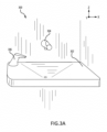
- FIGS. 3A and 3B a perspective view and a side view, respectively, of a sink 302 within a lavatory, such as lavatory 200 of FIG. 2 , disposed within a fuselage 110 of the aircraft 100 from FIG. 1 are illustrated, in accordance with various embodiments.
- the sink 302 has an associated touchless water faucet 304 and an associated touchless soap dispenser 306.
- a target object such as a passenger's hands, may be placed beneath the touchless soap dispenser 306 to have soap dispensed onto the target object or beneath the touchless water faucet 304 to have water dispensed onto the target object.
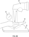
- a microcontroller within the touchless water faucet 304, sends a command to an infrared emitter, i.e. an infrared laser, to have a photons emitted in a predefined direction, i.e. toward an area where the water will be dispensed and thus, where the target object will be detected.
- the infrared emitter is configured to emit the photon.
- an infrared receiver within the touchless device and under command of the microcontroller is configured to receive the reflected photon after the photon has reflected off a surface, i.e. a sink or a target object, among others.
- the microcontroller determines a time-of-flight 310 to detect the target object's distance from the infrared emitter and the infrared receiver.
- the microcontroller responsive to the target object 308 being placed beneath the touchless water faucet 304 to have water dispensed onto the target object 308 and responsive to the microcontroller determining that the target object's 308 distance is within a predefined range, then the microcontroller is configured to send a command to an actuator on a dispensing valve, within the touchless water faucet 304.
- the predefined range may be between 3 cm (1.181 inches) and 15 cm (5.906 inches). In various embodiments, the predefined range may be between 6 cm (2.362 inches) and 12 cm (4.724 inches). In various embodiments, the predefined range may be between 8 cm (3.15 inches) and 10 cm (3.937 inches). In various embodiments, in response to receiving the command, the actuator on the dispensing valve is configured to activate to allow a liquid to be dispensed.
- the touchless device 400 includes a microcontroller 402, an infrared emitter 404, i.e. an infrared laser, an infrared receiver 406, and a dispensing valve 408.
- the infrared emitter 404, the infrared receiver 406, and the dispensing valve 408 are electrically and communicatively coupled to the microcontroller 402.
- the microcontroller 402 may receive electrical power 403 from the aircraft and distribute the electrical power to the infrared emitter 404, the infrared receiver 406, and the dispensing valve 408.
- the infrared emitter 404 and the infrared receiver 406 may be configured in a single time-of-flight sensor.
- the microcontroller 402 includes one or more logic devices and a memory.
- the one or more logic devices may be one or more of a central processing unit (CPU), an accelerated processing unit (APU), a digital signal processor (DSP), a field programmable gate array (FPGA), an application specific integrated circuit (ASIC), or the like (e.g., the microcontroller 402 may utilize one or more processors of any appropriate type/configuration, may utilize any appropriate processing architecture, or both).
- the memory may include any non-transitory memory known in the art. The memory may store instructions usable by the logic device to perform operations. Any appropriate computer-readable type/configuration may be utilized as the memory, any appropriate data storage architecture may be utilized by the memory, or both.
- the memory may be integral to the microcontroller 402 or may be located remote from the microcontroller 402.
- the one or more logic devices may communicate with the memory via any wired or wireless protocol. In that regard, the one or more logic devices may access data stored in the memory.
- the microcontroller 402 may be integrated into computer systems onboard the aircraft 100 from FIG. 1 .
- any number of conventional techniques for electronics configuration, signal processing and/or control, data processing and the like may be employed.
- the processes, functions, and instructions may include software routines in conjunction with processors, etc.
- System program instructions and/or controller instructions may be loaded onto a non-transitory, tangible computer-readable medium having instructions stored thereon that, in response to execution by the processor, cause the microcontroller 402 to perform various operations.
- non-transitory is to be understood to remove only propagating transitory signals per se from the claim scope and does not relinquish rights to all standard computer-readable media that are not only propagating transitory signals per se.
- the microcontroller 402 sends a command to the infrared emitter 404 to have a photon emitted in a predefined direction, i.e. toward an area where the liquid will be dispensed and thus, where the target object will be detected.
- the infrared emitter 404 responsive to receiving the command, is configured to emit a photon toward an area where the liquid will be dispensed.
- the infrared receiver 406 is configured to receive the photon after the photon has reflected off a surface, i.e. a sink or a target object, among others, and send a signal to the microcontroller 402.
- the microcontroller 402 is configured to determine a target object's distance from the infrared emitter 404 and the infrared receiver 406 based on a time-of-flight between the infrared emitter 404 emitting the photon and the infrared receiver 406 receiving the photon. In various embodiments, if the target object's distance is within a predefined range, then the microcontroller 402 is configured send an activation command to an actuator on the dispensing valve 408. In various embodiments, in response to receiving the activation command, the actuator on the dispensing valve 408 is configured to activate to allow a liquid 410, such as water or soap, among others, to be dispensed via a conduit 412.
- a liquid 410 such as water or soap, among others
- the liquid 410 may be fluidly coupled to the dispensing valve 408 and the conduit 412 may be fluidly coupled to the dispensing valve 408.
- an aerator 414 may be disposed between the dispensing valve 408 and the conduit 412. In various embodiments, if the target object's distance is outside the predefined range, then the microcontroller 402 continues to operate to identify a next target object's distance.
- the microcontroller 402 responsive to the actuator on the dispensing valve 408 being activated, continues to command the infrared emitter 404 and the infrared receiver to send and receive photons, respectively, and thus, the microcontroller 402 continuously or substantially continuously determines a target object's distance from the infrared emitter 404 and the infrared receiver 406 based on a time-of-flight between the infrared emitter 404 emitting the photon and the infrared receiver 406 receiving the photon. In various embodiments, if the target object's distance falls outside the predefined range, then the microcontroller 402 is configured send a deactivation command to the actuator on the dispensing valve 408.
- the actuator on the dispensing valve 408 in response to receiving the deactivation command, is configured to deactivate to prevent the liquid 410, such as water or soap, among others, from being dispensed.
- the touchless device 400 further includes a manual override 416.
- the manual override 416 provide for manual activation of the actuator on the dispensing valve 408 via the microcontroller 402 in events, such as maintenance.
- the microcontroller sends a command to an infrared emitter to have the infrared emitter emit a photon in a predefined direction, i.e. toward an area where the liquid will be dispensed and thus, where the target object will be detected.
- the infrared emitter responsive to receiving the command, is configured to emit a photon toward an area where the water will be dispensed.
- the microcontroller sends a command to an infrared receiver to receive the photon after the photon has reflected off a surface, i.e.
- the microcontroller determines a target object's distance from the infrared emitter and the infrared receiver based on a time-of-flight between the infrared emitter emitting the photon and the infrared receiver receiving the photon.
- the microcontroller compares the determined target object's distance to a predefined range.
- the microcontroller sends an activation command to an actuator on a dispensing valve, thereby causing the actuator on the dispensing valve to activate to allow a liquid, such as water or soap, among others, to be dispensed, with the operation returning to block 502 thereafter. If at block 508 the determined target object's distance falls outside the predefined range, then at block 512, the microcontroller sends a deactivation command to the actuator on the dispensing valve, thereby causing the actuator on the dispensing valve to deactivate to prevent the liquid from being dispensed, with the operation returning to block 502 thereafter
- references to "one embodiment,” “an embodiment,” “various embodiments,” etc. indicate that the embodiment described may include a particular feature, structure, or characteristic, but every embodiment may not necessarily include the particular feature, structure, or characteristic. Moreover, such phrases are not necessarily referring to the same embodiment. Further, when a particular feature, structure, or characteristic is described in connection with an embodiment, it is submitted that it is within the knowledge of one skilled in the art to affect such feature, structure, or characteristic in connection with other embodiments whether or not explicitly described. After reading the description, it will be apparent to one skilled in the relevant art(s) how to implement the disclosure in alternative embodiments.
Landscapes
- Physics & Mathematics (AREA)
- Engineering & Computer Science (AREA)
- Electromagnetism (AREA)
- General Physics & Mathematics (AREA)
- Computer Networks & Wireless Communication (AREA)
- Remote Sensing (AREA)
- Radar, Positioning & Navigation (AREA)
- Life Sciences & Earth Sciences (AREA)
- Public Health (AREA)
- Aviation & Aerospace Engineering (AREA)
- Health & Medical Sciences (AREA)
- Geophysics (AREA)
- General Life Sciences & Earth Sciences (AREA)
- Hydrology & Water Resources (AREA)
- Water Supply & Treatment (AREA)
- Geophysics And Detection Of Objects (AREA)
- Optical Radar Systems And Details Thereof (AREA)
Abstract
A time-of-flight controlled touchless device (400) is disclosed. The time-of-flight controlled touchless device (400) includes a time-of-flight sensor (215, 216) and a microcontroller (402) in operable communication with the time-of-flight sensor (215, 216). The microcontroller (402) is configured to command the time-of-flight sensor (215, 216) to emit a photon in a predefined direction, command the time-of-flight sensor (215, 216) to receive the photon reflected off a surface, determine a target object's (308) distance based on a time-of-flight between emitting the photon and receiving the photon, compare the target object's (308) distance to a predefined range, and, responsive to the target object's distance being within the predefined range, command an actuator on a dispensing valve (408) to activate to dispense a liquid (410).
Description
- The present disclosure relates generally to improved sensor systems and methods and, more particularly, to improved sensor systems and methods for an aircraft lavatory.
- Typically, a lavatory of an aircraft includes many surfaces that require activation, such as a faucet, a soap dispenser, a waste flap, a toilet flush, a toilet seat, and a toilet, among others. Typical lavatory systems have manually activated switches for activation of these surfaces. In recent years, infrared technology has been used to activate devices such as a touchless faucet or a touchless soap dispenser, among others. However, a conventional infrared touchless soap dispenser and a touchless water faucet, placed in close proximity within an aircraft lavatory sink, are typically susceptible to false activation and low performance due to the color, size, and reflectance dependency of the target object.
- A time-of-flight controlled touchless device is disclosed herein. The time-of-flight controlled touchless device includes a time-of-flight sensor and a microcontroller in operable communication with the time-of-flight sensor. The microcontroller is configured to: command the time-of-flight sensor to emit a photon in a predefined direction, wherein the time-of-flight sensor includes an infrared laser that emits the photon; command the time-of-flight sensor to receive the photon reflected off a surface; determine a target object's distance based on a time-of-flight between emitting the photon and receiving the photon; compare the target object's distance to a predefined range; and, responsive to the target object's distance being within the predefined range, command an actuator on the dispensing valve to activate to dispense a liquid.
- In various embodiments, the microcontroller is further configured to: responsive to the target object's distance being outside the predefined range, command the actuator on the dispensing valve to deactivate to prevent the liquid from dispensing. In various embodiments, the time-of-flight controlled touchless device further includes the dispensing valve. In various embodiments, the actuator on the dispensing valve is configured to: activate responsive to receiving an activation command from the microcontroller; and deactivate responsive to receiving a deactivation command from the microcontroller. In various embodiments, the dispensing valve dispenses at least one of water or soap.
- In various embodiments, the time-of-flight sensor includes an infrared emitter configured to emit the photon in the predefined direction responsive to receiving a command from the microcontroller. In various embodiments, the time-of-flight sensor comprises an infrared receiver configured to receive the photon reflected off the surface responsive to receiving a command from the microcontroller. In various embodiments, the time-of-flight controlled touchless device further includes a manual override configured to manually activate the actuator on the dispensing valve to dispense the liquid. In various embodiments, the microcontroller is configured to receive electrical power and distribute the electrical power to the time-of-flight sensor and the dispensing valve.
- Also disclosed herein is an aircraft lavatory. The aircraft lavatory includes a time-of-flight controlled touchless device. The time-of-flight controlled touchless device includes a time-of-flight sensor and a microcontroller in operable communication with the time-of-flight sensor. The microcontroller is configured to: command the time-of-flight sensor to emit a photon in a predefined direction, wherein the time-of-flight sensor includes an infrared laser that emits the photon; command the time-of-flight sensor to receive the photon reflected off a surface; determine a target object's distance based on a time-of-flight between emitting the photon and receiving the photon; compare the target object's distance to a predefined range; and, responsive to the target object's distance being within the predefined range, command an actuator on a dispensing valve to activate to dispense a liquid.
- In various embodiments, the microcontroller is further configured to: responsive to the target object's distance being outside the predefined range, command the actuator on the dispensing valve to deactivate to prevent the liquid from dispensing. In various embodiments, the time-of-flight controlled touchless device further includes the dispensing valve. In various embodiments, the actuator on the dispensing valve is configured to: activate responsive to receiving an activation command from the microcontroller; and deactivate responsive to receiving a deactivation command from the microcontroller. In various embodiments, the dispensing valve dispenses at least one of water or soap.
- In various embodiments, the time-of-flight sensor includes an infrared emitter configured to emit the photon in the predefined direction responsive to receiving a command from the microcontroller. In various embodiments, the time-of-flight sensor includes an infrared receiver configured to receive the photon reflected off the surface responsive to receiving a command from the microcontroller. In various embodiments, the time-of-flight controlled touchless device further includes a manual override configured to manually activate the actuator on the dispensing valve to dispense the liquid. In various embodiments, the microcontroller is configured to receive electrical power and distribute the electrical power to the time-of-flight sensor and the dispensing valve.
- Also disclosed herein is a method of operating a time-of-flight controlled touchless device. The method includes commanding, by a microcontroller, a time-of-flight sensor to emit a photon in a predefined direction, wherein the time-of-flight sensor includes an infrared laser that emits the photon; commanding, by the microcontroller, the time-of-flight sensor to receive the photon reflected off a surface; determining, by the microcontroller, a target object's distance based on a time-of-flight between emitting the photon and receiving the photon; comparing, by the microcontroller, the target object's distance to a predefined range; and, responsive to the target object's distance being within the predefined range, commanding, by the microcontroller, an actuator on a dispensing valve to activate to dispense a liquid.
- In various embodiments, the method further includes, responsive to the target object's distance being outside the predefined range, commanding, by the microcontroller, the actuator on the dispensing valve to deactivate to prevent the liquid from dispensing. In various embodiments, the time-of-flight sensor includes an infrared emitter to emit the photon in the predefined direction and an infrared receiver to receive the photon reflected off the surface. In various embodiments, the predefined direction is an area where the liquid will be dispensed.
- The forgoing features and elements may be combined in various combinations without exclusivity, unless expressly indicated herein otherwise. These features and elements as well as the operation of the disclosed embodiments will become more apparent in light of the following description and accompanying drawings.
- The subject matter of the present disclosure is particularly pointed out and distinctly claimed in the concluding portion of the specification. A more complete understanding of the present disclosure, however, may best be obtained by referring to the following detailed description and claims in connection with the following drawings. While the drawings illustrate various embodiments employing the principles described herein, the drawings do not limit the scope of the claims.
-
FIG. 1 illustrates a front view of an aircraft, in accordance with various embodiments. -
FIG. 2 illustrates a perspective view of a lavatory disposed within a fuselage of an aircraft, in accordance with various embodiments. -
FIGS. 3A and3B illustrate a perspective view and a side view, respectively, of a sink within a lavatory disposed within a fuselage of an aircraft, in accordance with various embodiments. -
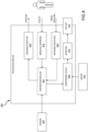
FIG. 4 illustrates a schematic view of touchless device configures with a time-of-flight sensor, in accordance with various embodiments; and -
FIG. 5 illustrates a flow chart for operating a time-of-flight controlled touchless device, in accordance with various embodiments. - The following detailed description of various embodiments herein makes reference to the accompanying drawings, which show various embodiments by way of illustration. While these various embodiments are described in sufficient detail to enable those skilled in the art to practice the disclosure, it should be understood that other embodiments may be realized and that changes may be made without departing from the scope of the disclosure. Thus, the detailed description herein is presented for purposes of illustration only and not of limitation. Furthermore, any reference to singular includes plural embodiments, and any reference to more than one component or step may include a singular embodiment or step. Also, any reference to attached, fixed, connected, or the like may include permanent, removable, temporary, partial, full or any other possible attachment option. Additionally, any reference to without contact (or similar phrases) may also include reduced contact or minimal contact. It should also be understood that unless specifically stated otherwise, references to "a," "an," or "the" may include one or more than one and that reference to an item in the singular may also include the item in the plural. Further, all ranges may include upper and lower values and all ranges and ratio limits disclosed herein may be combined.
- As stated previously, a lavatory of an aircraft includes many surfaces that require activation, such as a faucet, a soap dispenser, a waste flap, a toilet flush, a toilet seat, and a toilet, among others. Infrared technology has been used to activate devices such as a touchless faucet or a touchless soap dispenser, among others. However, a conventional infrared touchless soap dispenser and a touchless water faucet, placed in close proximity within an aircraft lavatory sink, are typically susceptible to false activation and low performance due to the color, size, and reflectance dependency of the target object.
- Disclosed herein is a touchless device for a lavatory of an aircraft that utilizes a time-of-flight (ToF) to detect the target object's distance and activate the touchless device in response to the target object being within an area of defined activation range. In various embodiments, an infrared emitter, i.e. an infrared laser, within the touchless device and under command of a microcontroller within the touchless device, is configured to emit a photon. In various embodiments, an infrared receiver within the touchless device and under command of the microcontroller, is configured to receive the photon after the photon has reflected off a surface, i.e. a sink or a target object, among others. In various embodiments, based on a time between the infrared emitter emitting the photon and the infrared receiver receiving the photon, the microcontroller determines a time-of-flight to detect the target object's distance from the infrared emitter and the infrared receiver. In various embodiments, if the target object's distance is within a predefined range, then the microcontroller is configured to send a command to an actuator on a dispensing valve. In various embodiments, in response to receiving the command, the actuator on the dispensing valve is configured to activate to allow a liquid, such as water or soap, among others, or to actuate a flushometer or the like to be dispensed.
- Referring now to
FIG. 1 , a front view of anaircraft 100 is illustrated. in accordance with various embodiments. Theaircraft 100 comprises afuselage 110,wings 120 extending outward from thefuselage 110, alanding gear system 130, avertical stabilizer 140,horizontal stabilizers 150, andengines 160. In various embodiments,fuselage 110 defines an aircraft cabin therein. In this regard, in various embodiments, passengers may board theaircraft 100 and sit within the aircraft cabin during travel. In various embodiments, the aircraft cabin includes at least one lavatory disposed therein, as described further herein. In various embodiments, aircraft lavatories may have limited space within the aircraft cabin in order to maximize passenger space and/or limit drag of theaircraft 100 during flight. In this regard, in various embodiments, a time-of-flight enable touchless device within the lavatory of theaircraft 100 provides for the touchless device to operate reliably with an optimal range of interest for object detection. In various embodiments, a time-of-flight ranging may be independent of color, size, and reflectance of the target object, which may aid in activation of the touchless device only when intended. - Referring now to
FIG. 2 , a perspective view of alavatory 200 disposed within afuselage 110 of theaircraft 100 fromFIG. 1 is illustrated, in accordance with various embodiments. In various embodiments, thelavatory 200 includes a plurality of sensors 210 (e.g., asensors sensors 210 may be disposed proximate a device which the respective sensor is configured to activate. For example,sensor 211 is disposed proximate a toilet and configured to activate a flush system associated with the toilet. In various embodiments, in a confined space, such as alavatory 200 of an aircraft, various sensors of the plurality ofsensors 210 may be susceptible to false activation and low performance due to the color, size, and reflectance dependency of the target object leading to sub-optimal use of limited resources on board theaircraft 100 fromFIG. 1 . In that regard, in various embodiments, various sensors of the plurality ofsensors 210, such assensors sensors 210, such assensors - Referring now to
FIGS. 3A and3B , a perspective view and a side view, respectively, of asink 302 within a lavatory, such aslavatory 200 ofFIG. 2 , disposed within afuselage 110 of theaircraft 100 fromFIG. 1 are illustrated, in accordance with various embodiments. In various embodiments, thesink 302 has an associatedtouchless water faucet 304 and an associatedtouchless soap dispenser 306. In various embodiments, a target object, such as a passenger's hands, may be placed beneath thetouchless soap dispenser 306 to have soap dispensed onto the target object or beneath thetouchless water faucet 304 to have water dispensed onto the target object. - With particular reference to
FIG. 3B , a microcontroller, within thetouchless water faucet 304, sends a command to an infrared emitter, i.e. an infrared laser, to have a photons emitted in a predefined direction, i.e. toward an area where the water will be dispensed and thus, where the target object will be detected. In that regard, in various embodiments, the infrared emitter is configured to emit the photon. In various embodiments, an infrared receiver within the touchless device and under command of the microcontroller, is configured to receive the reflected photon after the photon has reflected off a surface, i.e. a sink or a target object, among others. In various embodiments, based on a time between the infrared emitter emitting the photon and the infrared receiver receiving the photon, the microcontroller determines a time-of-flight 310 to detect the target object's distance from the infrared emitter and the infrared receiver. In that regard, responsive to thetarget object 308 being placed beneath thetouchless water faucet 304 to have water dispensed onto thetarget object 308 and responsive to the microcontroller determining that the target object's 308 distance is within a predefined range, then the microcontroller is configured to send a command to an actuator on a dispensing valve, within thetouchless water faucet 304. In various embodiments, the predefined range may be between 3 cm (1.181 inches) and 15 cm (5.906 inches). In various embodiments, the predefined range may be between 6 cm (2.362 inches) and 12 cm (4.724 inches). In various embodiments, the predefined range may be between 8 cm (3.15 inches) and 10 cm (3.937 inches). In various embodiments, in response to receiving the command, the actuator on the dispensing valve is configured to activate to allow a liquid to be dispensed. - Referring now to
FIG. 4 , a schematic view of touchless device configures with a time-of-flight sensor is illustrated, in accordance with various embodiments. In various embodiments, thetouchless device 400 includes amicrocontroller 402, aninfrared emitter 404, i.e. an infrared laser, aninfrared receiver 406, and a dispensingvalve 408. In various embodiments, theinfrared emitter 404, theinfrared receiver 406, and the dispensingvalve 408 are electrically and communicatively coupled to themicrocontroller 402. In that regards, themicrocontroller 402 may receiveelectrical power 403 from the aircraft and distribute the electrical power to theinfrared emitter 404, theinfrared receiver 406, and the dispensingvalve 408. In various embodiments, theinfrared emitter 404 and theinfrared receiver 406 may be configured in a single time-of-flight sensor. - In various embodiments, the
microcontroller 402 includes one or more logic devices and a memory. In various embodiments, the one or more logic devices may be one or more of a central processing unit (CPU), an accelerated processing unit (APU), a digital signal processor (DSP), a field programmable gate array (FPGA), an application specific integrated circuit (ASIC), or the like (e.g., themicrocontroller 402 may utilize one or more processors of any appropriate type/configuration, may utilize any appropriate processing architecture, or both). In various embodiments, the memory may include any non-transitory memory known in the art. The memory may store instructions usable by the logic device to perform operations. Any appropriate computer-readable type/configuration may be utilized as the memory, any appropriate data storage architecture may be utilized by the memory, or both. - The memory may be integral to the
microcontroller 402 or may be located remote from themicrocontroller 402. The one or more logic devices may communicate with the memory via any wired or wireless protocol. In that regard, the one or more logic devices may access data stored in the memory. In various embodiments, themicrocontroller 402 may be integrated into computer systems onboard theaircraft 100 fromFIG. 1 . Furthermore, any number of conventional techniques for electronics configuration, signal processing and/or control, data processing and the like may be employed. Also, the processes, functions, and instructions may include software routines in conjunction with processors, etc. - System program instructions and/or controller instructions may be loaded onto a non-transitory, tangible computer-readable medium having instructions stored thereon that, in response to execution by the processor, cause the
microcontroller 402 to perform various operations. The term "non-transitory" is to be understood to remove only propagating transitory signals per se from the claim scope and does not relinquish rights to all standard computer-readable media that are not only propagating transitory signals per se. - In various embodiments, the
microcontroller 402 sends a command to theinfrared emitter 404 to have a photon emitted in a predefined direction, i.e. toward an area where the liquid will be dispensed and thus, where the target object will be detected. In that regard, responsive to receiving the command, theinfrared emitter 404 is configured to emit a photon toward an area where the liquid will be dispensed. In various embodiments, theinfrared receiver 406 is configured to receive the photon after the photon has reflected off a surface, i.e. a sink or a target object, among others, and send a signal to themicrocontroller 402. In various embodiments, themicrocontroller 402 is configured to determine a target object's distance from theinfrared emitter 404 and theinfrared receiver 406 based on a time-of-flight between theinfrared emitter 404 emitting the photon and theinfrared receiver 406 receiving the photon. In various embodiments, if the target object's distance is within a predefined range, then themicrocontroller 402 is configured send an activation command to an actuator on the dispensingvalve 408. In various embodiments, in response to receiving the activation command, the actuator on the dispensingvalve 408 is configured to activate to allow a liquid 410, such as water or soap, among others, to be dispensed via aconduit 412. In that regard, the liquid 410 may be fluidly coupled to the dispensingvalve 408 and theconduit 412 may be fluidly coupled to the dispensingvalve 408. In various embodiments, anaerator 414 may be disposed between the dispensingvalve 408 and theconduit 412. In various embodiments, if the target object's distance is outside the predefined range, then themicrocontroller 402 continues to operate to identify a next target object's distance. - In various embodiments, responsive to the actuator on the dispensing
valve 408 being activated, themicrocontroller 402 continues to command theinfrared emitter 404 and the infrared receiver to send and receive photons, respectively, and thus, themicrocontroller 402 continuously or substantially continuously determines a target object's distance from theinfrared emitter 404 and theinfrared receiver 406 based on a time-of-flight between theinfrared emitter 404 emitting the photon and theinfrared receiver 406 receiving the photon. In various embodiments, if the target object's distance falls outside the predefined range, then themicrocontroller 402 is configured send a deactivation command to the actuator on the dispensingvalve 408. In various embodiments, in response to receiving the deactivation command, the actuator on the dispensingvalve 408 is configured to deactivate to prevent the liquid 410, such as water or soap, among others, from being dispensed. In various embodiments, thetouchless device 400 further includes amanual override 416. In various embodiments, themanual override 416 provide for manual activation of the actuator on the dispensingvalve 408 via themicrocontroller 402 in events, such as maintenance. - Referring now to
FIG. 5 , a flow chart 500 for operating a time-of-flight controlled touchless device is illustrated, in accordance with various embodiments. Atblock 502, the microcontroller sends a command to an infrared emitter to have the infrared emitter emit a photon in a predefined direction, i.e. toward an area where the liquid will be dispensed and thus, where the target object will be detected. In that regard, responsive to receiving the command, the infrared emitter is configured to emit a photon toward an area where the water will be dispensed. Atblock 504, the microcontroller sends a command to an infrared receiver to receive the photon after the photon has reflected off a surface, i.e. a sink or a target object, among others, and send a received signal to the microcontroller. Atblock 506, the microcontroller determines a target object's distance from the infrared emitter and the infrared receiver based on a time-of-flight between the infrared emitter emitting the photon and the infrared receiver receiving the photon. Atblock 508, the microcontroller compares the determined target object's distance to a predefined range. If atblock 508 the determined target object's distance is within the predefined range, then atblock 510, the microcontroller sends an activation command to an actuator on a dispensing valve, thereby causing the actuator on the dispensing valve to activate to allow a liquid, such as water or soap, among others, to be dispensed, with the operation returning to block 502 thereafter. If atblock 508 the determined target object's distance falls outside the predefined range, then atblock 512, the microcontroller sends a deactivation command to the actuator on the dispensing valve, thereby causing the actuator on the dispensing valve to deactivate to prevent the liquid from being dispensed, with the operation returning to block 502 thereafter - Benefits, other advantages, and solutions to problems have been described herein with regard to specific embodiments. Furthermore, the connecting lines shown in the various figures contained herein are intended to represent exemplary functional relationships and/or physical couplings between the various elements. It should be noted that many alternative or additional functional relationships or physical connections may be present in a practical system. However, the benefits, advantages, solutions to problems, and any elements that may cause any benefit, advantage, or solution to occur or become more pronounced are not to be construed as critical, required, or essential features or elements of the disclosure. The scope of the disclosure is accordingly to be limited by nothing other than the appended claims, in which reference to an element in the singular is not intended to mean "one and only one" unless explicitly so stated, but rather "one or more." Moreover, where a phrase similar to "at least one of A, B, or C" is used in the claims, it is intended that the phrase be interpreted to mean that A alone may be present in an embodiment, B alone may be present in an embodiment, C alone may be present in an embodiment, or that any combination of the elements A, Band C may be present in a single embodiment; for example, A and B, A and C, B and C, or A and B and C. Different cross-hatching is used throughout the figures to denote different parts but not necessarily to denote the same or different materials.
- Systems, methods and apparatus are provided herein. In the detailed description herein, references to "one embodiment," "an embodiment," "various embodiments," etc., indicate that the embodiment described may include a particular feature, structure, or characteristic, but every embodiment may not necessarily include the particular feature, structure, or characteristic. Moreover, such phrases are not necessarily referring to the same embodiment. Further, when a particular feature, structure, or characteristic is described in connection with an embodiment, it is submitted that it is within the knowledge of one skilled in the art to affect such feature, structure, or characteristic in connection with other embodiments whether or not explicitly described. After reading the description, it will be apparent to one skilled in the relevant art(s) how to implement the disclosure in alternative embodiments.
- Furthermore, no element, component, or method step in the present disclosure is intended to be dedicated to the public regardless of whether the element, component, or method step is explicitly recited in the claims. As used herein, the terms "comprises," "comprising," or any other variation thereof, are intended to cover a non-exclusive inclusion, such that a process, method, article, or apparatus that comprises a list of elements does not include only those elements but may include other elements not expressly listed or inherent to such process, method, article, or apparatus.
- Finally, it should be understood that any of the above-described concepts can be used alone or in combination with any or all of the other above-described concepts. Although various embodiments have been disclosed and described, one of ordinary skill in this art would recognize that certain modifications would come within the scope of this disclosure. Accordingly, the description is not intended to be exhaustive or to limit the principles described or illustrated herein to any precise form. Many modifications and variations are possible in light of the above teaching.
Claims (15)
- A time-of-flight controlled touchless device (400), comprising:a time-of-flight sensor (215, 216); anda microcontroller (402) in operable communication with the time-of-flight sensor (215, 216), the microcontroller (402) configured to:command the time-of-flight sensor (215, 216) to emit a photon in a predefined direction, wherein the time-of-flight sensor (215, 216) includes an infrared laser (404) that emits the photon;command the time-of-flight sensor (215, 216) to receive the photon reflected off a surface;determine a target object's (308) distance based on a time-of-flight between emitting the photon and receiving the photon;compare the target object's (308) distance to a predefined range; andresponsive to the target object's (308) distance being within the predefined range, command an actuator on a dispensing valve (408) to activate to dispense a liquid (410).
- The time-of-flight controlled touchless device of claim 1, wherein the microcontroller (402) is further configured to:
responsive to the target object's (308) distance being outside the predefined range, command the actuator on the dispensing valve (408) to deactivate to prevent the liquid (410) from dispensing. - The time-of-flight controlled touchless device of claim 1 or claim 2, further comprising:the dispensing valve (408), wherein the actuator on the dispensing valve (408) is configured to:activate responsive to receiving an activation command from the microcontroller (402); anddeactivate responsive to receiving a deactivation command from the microcontroller (402), and optionally:wherein the dispensing valve (408) dispenses at least one of water or soap.
- The time-of-flight controlled touchless device of any preceding claims, wherein the time-of-flight sensor (215, 216) comprises an infrared emitter (404) configured to emit the photon in the predefined direction responsive to receiving a command from the microcontroller, and/or;
wherein the time-of-flight sensor comprises an infrared receiver (406) configured to receive the photon reflected off the surface responsive to receiving a command from the microcontroller (402).. - The time-of-flight controlled touchless device of any preceding claims, further comprising:
a manual override configured to manually activate the actuator on the dispensing valve (408) to dispense the liquid (410). - The time-of-flight controlled touchless device of any preceding claims, wherein the microcontroller (402) is configured to receive electrical power (403) and distribute the electrical power (403) to the time-of-flight sensor and the dispensing valve (408).
- An aircraft lavatory, comprising:
the time-of-flight controlled touchless device (400) of claim 1. - The aircraft lavatory of claim 7, wherein the microcontroller (402) is further configured to:
responsive to the target object's (308) distance being outside the predefined range, command the actuator on the dispensing valve (408) to deactivate to prevent the liquid (410) from dispensing. - The aircraft lavatory of claim 7 or claim 8, wherein the time-of-flight controlled touchless device (400) further comprises:
the dispensing valve (408), wherein the actuator on the dispensing valve (408) is configured to:activate responsive to receiving an activation command from the microcontroller (402); anddeactivate responsive to receiving a deactivation command from the microcontroller (402), and optionally:
wherein the dispensing valve (408) dispenses at least one of water or soap. - The aircraft lavatory of claim 7, 8 or 9, wherein the time-of-flight sensor (215, 216) comprises an infrared emitter (404) configured to emit the photon in the predefined direction responsive to receiving a command from the microcontroller (402), and/or;
wherein the time-of-flight sensor (215, 216) comprises an infrared receiver (406) configured to receive the photon reflected off the surface responsive to receiving a command from the microcontroller (402). - The aircraft lavatory of any of claims 7 to 10, wherein the time-of-flight controlled touchless device (400) further comprises:
a manual override configured to manually activate the actuator on the dispensing valve (408) to dispense the liquid (410). - The aircraft lavatory of any of claims 7 to 11, wherein the microcontroller (402) is configured to receive electrical power (403) and distribute the electrical power (403) to the time-of-flight sensor (215, 216) and the dispensing valve (408).
- A method of operating a time-of-flight controlled touchless device (400), the method comprising:commanding, by a microcontroller (402), a time-of-flight sensor (215, 216) to emit a photon in a predefined direction, wherein the time-of-flight sensor includes an infrared laser (404) that emits the photon;commanding, by the microcontroller (402), the time-of-flight sensor (215, 216) to receive the photon reflected off a surface;determining, by the microcontroller (402), a target object's (308) distance based on a time-of-flight between emitting the photon and receiving the photon;comparing, by the microcontroller (402), the target object's (308) distance to a predefined range; andresponsive to the target object's distance being within the predefined range, commanding, by the microcontroller (402), an actuator on a dispensing valve (408) to activate to dispense a liquid (410).
- The method of claim 13, further comprising:
responsive to the target object's distance being outside the predefined range, commanding, by the microcontroller (402), the actuator on the dispensing valve (408) to deactivate to prevent the liquid (410) from dispensing. - The method of claim 13 or 14, wherein the time-of-flight sensor (215, 216) includes an infrared emitter (404) to emit the photon in the predefined direction and an infrared receiver (406) to receive the photon reflected off the surface and/or,
wherein the predefined direction is an area where the liquid (410) will be dispensed..
Applications Claiming Priority (1)
| Application Number | Priority Date | Filing Date | Title |
|---|---|---|---|
| US18/449,285 US20250059744A1 (en) | 2023-08-14 | 2023-08-14 | Touchless lavatory optical time of flight proximity |
Publications (1)
| Publication Number | Publication Date |
|---|---|
| EP4509877A1 true EP4509877A1 (en) | 2025-02-19 |
Family
ID=92409165
Family Applications (1)
| Application Number | Title | Priority Date | Filing Date |
|---|---|---|---|
| EP24194340.6A Pending EP4509877A1 (en) | 2023-08-14 | 2024-08-13 | Touchless lavatory optical time of flight proximity sensor |
Country Status (2)
| Country | Link |
|---|---|
| US (1) | US20250059744A1 (en) |
| EP (1) | EP4509877A1 (en) |
Citations (3)
| Publication number | Priority date | Publication date | Assignee | Title |
|---|---|---|---|---|
| US20150268342A1 (en) * | 2014-03-19 | 2015-09-24 | Masco Canada Limited | Time of flight proximity sensor |
| WO2021262942A1 (en) * | 2020-06-24 | 2021-12-30 | Sloan Valve Company | Hybrid time-of-flight sensor and ir sensor |
| EP4105894A1 (en) * | 2021-06-17 | 2022-12-21 | B/E Aerospace, Inc. | Sensor systems and methods for an aircraft lavatory |
Family Cites Families (15)
| Publication number | Priority date | Publication date | Assignee | Title |
|---|---|---|---|---|
| DE10005971A1 (en) * | 2000-02-09 | 2001-08-16 | Grohe Armaturen Friedrich | Water outlet fitting |
| US8456312B2 (en) * | 2003-02-10 | 2013-06-04 | Edward C. Wofford | Domestic water leak and humidity detection and control apparatus with water valve control |
| US7690395B2 (en) * | 2004-01-12 | 2010-04-06 | Masco Corporation Of Indiana | Multi-mode hands free automatic faucet |
| US9527656B2 (en) * | 2009-07-31 | 2016-12-27 | Seaquistperfect Dispensing L.L.C. | Touchless dispenser |
| FR3026119B1 (en) * | 2014-09-24 | 2016-12-02 | Celec Conception Electronique En Abrege Celec | INFRARED CONTROL DEVICE |
| CN108474846A (en) * | 2015-12-28 | 2018-08-31 | 松下知识产权经营株式会社 | Sensor and faucet device using the sensor |
| CA2965971C (en) * | 2016-05-09 | 2025-05-06 | Op-Hygiene Ip Gmbh | Fluid dispenser with time of flight proximity sensor |
| EP3624658A1 (en) * | 2017-05-19 | 2020-03-25 | Bradley Fixtures Corporation | Automatic paper towel dispenser with lidar sensor |
| US10994844B2 (en) * | 2018-10-26 | 2021-05-04 | The Boeing Company | Modular faucet system for aircraft |
| WO2021194958A1 (en) * | 2020-03-23 | 2021-09-30 | As America, Inc. | Automatic faucet |
| US12428262B2 (en) * | 2020-10-04 | 2025-09-30 | Mitsubishi Electric Research Laboratories, Inc. | Touchless elevator user interface |
| US20220305153A1 (en) * | 2021-03-23 | 2022-09-29 | B/E Aerospace, Inc. | Intelligent, configurable, and connected operation of uv lamps in aircraft lavatory |
| CN116964286A (en) * | 2021-03-26 | 2023-10-27 | As 美国股份有限公司 | mixer faucet components |
| EP4144927A3 (en) * | 2021-09-02 | 2023-05-24 | B/E Aerospace, Inc. | Touchless faucet |
| US12339417B2 (en) * | 2022-04-28 | 2025-06-24 | B/E Aerospace Inc. | Inadvertent operations in touchless lavatory |
-
2023
- 2023-08-14 US US18/449,285 patent/US20250059744A1/en active Pending
-
2024
- 2024-08-13 EP EP24194340.6A patent/EP4509877A1/en active Pending
Patent Citations (3)
| Publication number | Priority date | Publication date | Assignee | Title |
|---|---|---|---|---|
| US20150268342A1 (en) * | 2014-03-19 | 2015-09-24 | Masco Canada Limited | Time of flight proximity sensor |
| WO2021262942A1 (en) * | 2020-06-24 | 2021-12-30 | Sloan Valve Company | Hybrid time-of-flight sensor and ir sensor |
| EP4105894A1 (en) * | 2021-06-17 | 2022-12-21 | B/E Aerospace, Inc. | Sensor systems and methods for an aircraft lavatory |
Also Published As
| Publication number | Publication date |
|---|---|
| US20250059744A1 (en) | 2025-02-20 |
Similar Documents
| Publication | Publication Date | Title |
|---|---|---|
| US10208465B2 (en) | Infra-red control device | |
| EP3215447B1 (en) | Elevator passenger tracking control and call cancellation system | |
| US20150268342A1 (en) | Time of flight proximity sensor | |
| US20150239573A1 (en) | Apparatus and method to monitor the occupancy of seating | |
| US12122243B2 (en) | Method and system to ascertain location of drone box for stabilized landing and charging of drones | |
| WO2016160954A1 (en) | Maintenance mode for aircraft vacuum toilet | |
| US20180112379A1 (en) | Monitoring apparatus for a sanitary installation | |
| US20250059744A1 (en) | Touchless lavatory optical time of flight proximity | |
| CN112942517A (en) | Flushing control method and system of intelligent closestool | |
| US12467246B2 (en) | Automatic sanitaryware assembly and systems | |
| US12339417B2 (en) | Inadvertent operations in touchless lavatory | |
| US10457522B2 (en) | Limit switch system including first limit device and second limit device | |
| US10822115B2 (en) | Retrofittable display device for displaying an activation status of an emergency chute in an aircraft | |
| US20180170545A1 (en) | Adaptive optical sensor for container presence and motion | |
| EP4105894A1 (en) | Sensor systems and methods for an aircraft lavatory | |
| US11907433B2 (en) | Gesture-based systems and methods for aircraft cabin light control | |
| US20240263563A1 (en) | Engine inlet cover detection system and method | |
| US12313502B2 (en) | Water leak detection systems and methods for an internal cabin of an aircraft | |
| US9975627B2 (en) | Systems and methods for aircraft parking brakes with multiple control locations | |
| US20140015707A1 (en) | Systems and methods for providing diversity-distance-measuring equipment | |
| KR20200040178A (en) | Apparatus and Method for Rear Collision Avoiding, and Vehicle Control Apparatus with the same | |
| US20250034849A1 (en) | Sensor arrangement for detecting a person in an area of use of a sanitary facility | |
| US20240331461A1 (en) | Universal communication node | |
| EP4450389A2 (en) | Systems and methods for predicting system use and calibrating the predictions | |
| EP1600371B1 (en) | Control system for aircraft airbrakes |
Legal Events
| Date | Code | Title | Description |
|---|---|---|---|
| PUAI | Public reference made under article 153(3) epc to a published international application that has entered the european phase |
Free format text: ORIGINAL CODE: 0009012 |
|
| STAA | Information on the status of an ep patent application or granted ep patent |
Free format text: STATUS: THE APPLICATION HAS BEEN PUBLISHED |
|
| AK | Designated contracting states |
Kind code of ref document: A1 Designated state(s): AL AT BE BG CH CY CZ DE DK EE ES FI FR GB GR HR HU IE IS IT LI LT LU LV MC ME MK MT NL NO PL PT RO RS SE SI SK SM TR |
|
| STAA | Information on the status of an ep patent application or granted ep patent |
Free format text: STATUS: REQUEST FOR EXAMINATION WAS MADE |
|
| 17P | Request for examination filed |
Effective date: 20250728 |