EP4509782A1 - Trim breaker interface for reducing air infiltration in a vacuum insulated appliance - Google Patents
Trim breaker interface for reducing air infiltration in a vacuum insulated appliance Download PDFInfo
- Publication number
- EP4509782A1 EP4509782A1 EP24194689.6A EP24194689A EP4509782A1 EP 4509782 A1 EP4509782 A1 EP 4509782A1 EP 24194689 A EP24194689 A EP 24194689A EP 4509782 A1 EP4509782 A1 EP 4509782A1
- Authority
- EP
- European Patent Office
- Prior art keywords
- trim breaker
- breaker assembly
- foam gasket
- perimeter
- foam
- Prior art date
- Legal status (The legal status is an assumption and is not a legal conclusion. Google has not performed a legal analysis and makes no representation as to the accuracy of the status listed.)
- Withdrawn
Links
- 238000001764 infiltration Methods 0.000 title claims description 14
- 230000008595 infiltration Effects 0.000 title claims description 14
- 239000006260 foam Substances 0.000 claims abstract description 263
- 238000000034 method Methods 0.000 claims description 29
- 238000009413 insulation Methods 0.000 claims description 27
- 230000008878 coupling Effects 0.000 claims description 9
- 238000010168 coupling process Methods 0.000 claims description 9
- 238000005859 coupling reaction Methods 0.000 claims description 9
- 238000004519 manufacturing process Methods 0.000 claims description 7
- 229920005830 Polyurethane Foam Polymers 0.000 claims description 3
- 239000011496 polyurethane foam Substances 0.000 claims description 3
- 238000005057 refrigeration Methods 0.000 description 16
- 230000008569 process Effects 0.000 description 14
- 239000012774 insulation material Substances 0.000 description 7
- 239000000463 material Substances 0.000 description 6
- 230000008901 benefit Effects 0.000 description 5
- 238000006243 chemical reaction Methods 0.000 description 4
- VYPSYNLAJGMNEJ-UHFFFAOYSA-N Silicium dioxide Chemical compound O=[Si]=O VYPSYNLAJGMNEJ-UHFFFAOYSA-N 0.000 description 3
- 239000006227 byproduct Substances 0.000 description 3
- 229920005862 polyol Polymers 0.000 description 3
- 150000003077 polyols Chemical class 0.000 description 3
- 239000007787 solid Substances 0.000 description 3
- 239000000853 adhesive Substances 0.000 description 2
- 230000001070 adhesive effect Effects 0.000 description 2
- 238000010586 diagram Methods 0.000 description 2
- 239000012530 fluid Substances 0.000 description 2
- 239000012948 isocyanate Substances 0.000 description 2
- 150000002513 isocyanates Chemical class 0.000 description 2
- 239000000203 mixture Substances 0.000 description 2
- 239000004814 polyurethane Substances 0.000 description 2
- 229920002635 polyurethane Polymers 0.000 description 2
- 239000003507 refrigerant Substances 0.000 description 2
- OKTJSMMVPCPJKN-UHFFFAOYSA-N Carbon Chemical compound [C] OKTJSMMVPCPJKN-UHFFFAOYSA-N 0.000 description 1
- 239000004593 Epoxy Substances 0.000 description 1
- 230000000712 assembly Effects 0.000 description 1
- 238000000429 assembly Methods 0.000 description 1
- 238000005452 bending Methods 0.000 description 1
- 229910052799 carbon Inorganic materials 0.000 description 1
- 239000003054 catalyst Substances 0.000 description 1
- 239000007788 liquid Substances 0.000 description 1
- 229910052751 metal Inorganic materials 0.000 description 1
- 239000002184 metal Substances 0.000 description 1
- 229910001092 metal group alloy Inorganic materials 0.000 description 1
- 150000002739 metals Chemical class 0.000 description 1
- 229920000642 polymer Polymers 0.000 description 1
- 239000000843 powder Substances 0.000 description 1
- 230000009467 reduction Effects 0.000 description 1
- 230000004044 response Effects 0.000 description 1
- 239000000377 silicon dioxide Substances 0.000 description 1
- 229910052814 silicon oxide Inorganic materials 0.000 description 1
- 239000000126 substance Substances 0.000 description 1
Images







Classifications
-
- F—MECHANICAL ENGINEERING; LIGHTING; HEATING; WEAPONS; BLASTING
- F25—REFRIGERATION OR COOLING; COMBINED HEATING AND REFRIGERATION SYSTEMS; HEAT PUMP SYSTEMS; MANUFACTURE OR STORAGE OF ICE; LIQUEFACTION SOLIDIFICATION OF GASES
- F25D—REFRIGERATORS; COLD ROOMS; ICE-BOXES; COOLING OR FREEZING APPARATUS NOT OTHERWISE PROVIDED FOR
- F25D23/00—General constructional features
- F25D23/08—Parts formed wholly or mainly of plastics materials
- F25D23/082—Strips
- F25D23/085—Breaking strips
-
- F—MECHANICAL ENGINEERING; LIGHTING; HEATING; WEAPONS; BLASTING
- F25—REFRIGERATION OR COOLING; COMBINED HEATING AND REFRIGERATION SYSTEMS; HEAT PUMP SYSTEMS; MANUFACTURE OR STORAGE OF ICE; LIQUEFACTION SOLIDIFICATION OF GASES
- F25D—REFRIGERATORS; COLD ROOMS; ICE-BOXES; COOLING OR FREEZING APPARATUS NOT OTHERWISE PROVIDED FOR
- F25D11/00—Self-contained movable devices, e.g. domestic refrigerators
- F25D11/02—Self-contained movable devices, e.g. domestic refrigerators with cooling compartments at different temperatures
-
- F—MECHANICAL ENGINEERING; LIGHTING; HEATING; WEAPONS; BLASTING
- F25—REFRIGERATION OR COOLING; COMBINED HEATING AND REFRIGERATION SYSTEMS; HEAT PUMP SYSTEMS; MANUFACTURE OR STORAGE OF ICE; LIQUEFACTION SOLIDIFICATION OF GASES
- F25D—REFRIGERATORS; COLD ROOMS; ICE-BOXES; COOLING OR FREEZING APPARATUS NOT OTHERWISE PROVIDED FOR
- F25D23/00—General constructional features
- F25D23/06—Walls
- F25D23/062—Walls defining a cabinet
-
- F—MECHANICAL ENGINEERING; LIGHTING; HEATING; WEAPONS; BLASTING
- F25—REFRIGERATION OR COOLING; COMBINED HEATING AND REFRIGERATION SYSTEMS; HEAT PUMP SYSTEMS; MANUFACTURE OR STORAGE OF ICE; LIQUEFACTION SOLIDIFICATION OF GASES
- F25D—REFRIGERATORS; COLD ROOMS; ICE-BOXES; COOLING OR FREEZING APPARATUS NOT OTHERWISE PROVIDED FOR
- F25D23/00—General constructional features
- F25D23/06—Walls
- F25D23/065—Details
-
- F—MECHANICAL ENGINEERING; LIGHTING; HEATING; WEAPONS; BLASTING
- F25—REFRIGERATION OR COOLING; COMBINED HEATING AND REFRIGERATION SYSTEMS; HEAT PUMP SYSTEMS; MANUFACTURE OR STORAGE OF ICE; LIQUEFACTION SOLIDIFICATION OF GASES
- F25D—REFRIGERATORS; COLD ROOMS; ICE-BOXES; COOLING OR FREEZING APPARATUS NOT OTHERWISE PROVIDED FOR
- F25D23/00—General constructional features
- F25D23/06—Walls
- F25D23/069—Cooling space dividing partitions
-
- F—MECHANICAL ENGINEERING; LIGHTING; HEATING; WEAPONS; BLASTING
- F25—REFRIGERATION OR COOLING; COMBINED HEATING AND REFRIGERATION SYSTEMS; HEAT PUMP SYSTEMS; MANUFACTURE OR STORAGE OF ICE; LIQUEFACTION SOLIDIFICATION OF GASES
- F25D—REFRIGERATORS; COLD ROOMS; ICE-BOXES; COOLING OR FREEZING APPARATUS NOT OTHERWISE PROVIDED FOR
- F25D27/00—Lighting arrangements
-
- F—MECHANICAL ENGINEERING; LIGHTING; HEATING; WEAPONS; BLASTING
- F25—REFRIGERATION OR COOLING; COMBINED HEATING AND REFRIGERATION SYSTEMS; HEAT PUMP SYSTEMS; MANUFACTURE OR STORAGE OF ICE; LIQUEFACTION SOLIDIFICATION OF GASES
- F25D—REFRIGERATORS; COLD ROOMS; ICE-BOXES; COOLING OR FREEZING APPARATUS NOT OTHERWISE PROVIDED FOR
- F25D2201/00—Insulation
- F25D2201/10—Insulation with respect to heat
- F25D2201/14—Insulation with respect to heat using subatmospheric pressure
Definitions
- the present disclosure generally relates to a trim breaker interface formed by a foam gasket coupled to a trim breaker assembly, and more specifically, to a foam gasket coupled to a trim breaker assembly to define a seal for a vacuum insulated appliance and reduce air infiltration.
- a vacuum insulated refrigerator includes a cabinet defining a refrigerator compartment.
- the cabinet includes a liner, a wrapper, and a trim breaker assembly coupled to the liner and the wrapper.
- the trim breaker assembly extends along a perimeter of the refrigerator compartment.
- the trim breaker assembly includes a mullion region.
- At least one foam gasket is coupled to at least one surface of the trim breaker assembly.
- the at least one foam gasket is routed from a first end of the mullion region, along a portion of the perimeter of the refrigerator compartment, and to a second end of the mullion region.
- the at least one surface of the trim breaker assembly is at least one of an outer surface, a side surface, and an inner surface.
- At least one engagement member is configured to couple to the trim breaker assembly and define a seal by compressing the at least one foam gasket between the at least one engagement member and the trim breaker assembly.
- a vacuum insulated appliance includes a structural wrapper defining a freezer compartment.
- a trim breaker assembly is coupled to the structural wrapper.
- An insulation cavity is defined between the structural wrapper and the trim breaker assembly.
- the trim breaker assembly defines a perimeter of the freezer compartment and includes a mullion region.
- At least one foam gasket is coupled to at least one surface of the trim breaker assembly.
- the at least one foam gasket is routed from a first end of the mullion region, along a portion of the perimeter of the freezer compartment, and to a second end of the mullion region.
- the at least one surface of the trim breaker assembly includes at least one of an outer surface, a side surface, and an inner surface.
- At least one engagement member is coupled to the trim breaker assembly and define a seal by compressing the at least one foam gasket between the at least one engagement member and the trim breaker assembly to reduce air infiltration into the freezer compartment.
- a method for manufacturing a vacuum insulated structure includes providing a cabinet defining an insulation cavity and forming at least one compartment, the cabinet including a trim breaker assembly that extends along a perimeter of the at least one compartment, drawing an at least partial vacuum within the insulating cavity, applying at least one foam gasket to at least one surface of the trim breaker assembly along at least a portion of the perimeter of the at least one compartment, and coupling at least one engagement member with the trim breaker assembly to compress the at least one foam gasket therebetween and define a seal to reduce air infiltration between the at least one engagement member and the trim breaker assembly into the at least one compartment.
- the present illustrated embodiments reside primarily in combinations of method steps and apparatus components related to a foam gasket coupled to a trim breaker assembly. Accordingly, the apparatus components and method steps have been represented, where appropriate, by conventional symbols in the drawings, showing only those specific details that are pertinent to understanding the embodiments of the present disclosure so as not to obscure the disclosure with details that will be readily apparent to those of ordinary skill in the art having the benefit of the description herein. Further, like numerals in the description and drawings represent like elements.
- the terms “upper,” “lower,” “right,” “left,” “rear,” “front,” “vertical,” “horizontal,” and derivatives thereof shall relate to the disclosure as oriented in FIG. 1 .
- the term “front” shall refer to the surface of the element closer to an intended viewer, and the term “rear” shall refer to the surface of the element further from the intended viewer.
- the disclosure may assume various alternative orientations, except where expressly specified to the contrary.
- the specific devices and processes illustrated in the attached drawings, and described in the following specification are simply exemplary embodiments of the inventive concepts defined in the appended claims. Hence, specific dimensions and other physical characteristics relating to the embodiments disclosed herein are not to be considered as limiting, unless the claims expressly state otherwise.
- reference numeral 10 generally designates a vacuum insulated structure including a cabinet 12 defining at least one compartment, often including a refrigerator compartment 14 and a freezer compartment 16.
- the cabinet 12 includes a liner 18, a wrapper 20, and a trim breaker assembly 22 coupled to the liner 18 and the wrapper 20.
- the trim breaker assembly 22 extends along a perimeter 24 of the refrigerator compartment 14 and a perimeter 26 of the freezer compartment 16, and the trim breaker assembly 22 includes a mullion region 28.
- At least one refrigerator compartment (RC) foam gasket 30, which may include RC foam gaskets 30a-30c that are collectively referred to herein as the RC foam gaskets 30, is coupled to at least one surface 32 of the trim breaker assembly 22.
- At least one freezer compartment (FC) foam gasket 34 which may include FC foam gaskets 34a-34c that are collectively referred to herein as the FC foam gaskets 34, is coupled to the at least one surface 32 of the trim breaker assembly 22.
- FC foam gaskets 30 and FC foams gaskets 34 may also be referred to as the foam gaskets 30, 34.
- the RC foam gasket 30 is routed from a first end 36 of the mullion region 28, along a portion 38 of the perimeter 24 of the refrigerator compartment 14, and to a second end 40 of the mullion region 28.
- the FC foam gasket 34 is routed from the first end 36 of the mullion region 28, along a portion 42 of the perimeter 26 of the freezer compartment 16, and to the second end 40 of the mullion region 28.
- the at least one surface 32 of the trim breaker assembly 22 is at least one of an outer surface 44, which may include a first outer surface 44a and a second outer surface 44b, a side surface 46, which may include a first side surface 46a and a second side surface 46b, and an inner surface 48, which may include a first inner surface 48b and a second inner surface 48b.
- the first surfaces 44a, 46a, 48a generally extend along the perimeter of the refrigerator compartment 14 and the second surfaces 44b, 46b, 48b generally extend along the perimeter of the freezer compartment 16.
- At least one engagement member 50 which may include a plurality of engagement members 50, is configured to couple to the trim breaker assembly 22 to define at least one of a refrigerator compartment (RC) seal 52 by compressing the RC foam gasket 30.
- the RC seal 52 may include RC seals 52a-52c, which may be collectively referred to as the RC seals 52.
- the at least one engagement member 50 is configured to couple to the trim breaker assembly 22 to define at least one freezer compartment (FC) seal 54 by compressing the FC foam gasket 34.
- the FC seal 54 may include FC seals 54a-54c, which may be collectively referred to as FC seals 54.
- the vacuum insulated appliance 10 is illustrated as a refrigeration appliance.
- the refrigeration appliance 10 is illustrated as a bottom-mount refrigerator having an upper compartment configured as the refrigerator compartment 14 and a lower compartment configured as the freezer compartment 16.
- the cabinet 12 of the illustrated refrigeration appliance 10 includes a first insulated door 70a and a second insulated door 70b.
- the first insulated door 70a and the second insulated door 70b which can collectively be referred to as insulated doors 70, can have substantially similar configurations, as discussed further herein.
- the refrigerator and freezer compartments 14, 16 defined by the cabinet 12 can be sealed with the insulated doors 70a, 70b, respectively.
- the appliance 10 may include the cabinet 12 defining at least a first compartment and a second compartment sealed with insulated doors 70.
- the appliance 10 may be, for example, a bottom-mount French door refrigerator, a top-mount refrigerator, a side-by-side refrigerator, a 4-door French door refrigerator, and/or a 5-door French door refrigerator. Further, the present disclosure is not limited to refrigerators.
- the appliance 10 may be, for example, freezers, coolers, vacuum insulated structures, and other similar appliances and fixtures within household and commercial settings. Further, it is contemplated that the vacuum insulated appliance 10 disclosed herein may be for a variety of appliances, structures, panels, or assemblies for insulation purposes other than with an appliance.
- the cabinet 12 of the appliance 10 is an insulated structure having an insulation cavity 80 defined between the liner 18 and the wrapper 20.
- the insulated doors 70 are insulated structures having an insulation cavity 82 defined between a door wrapper 84 and a door liner 86.
- Each of the insulation cavities 80, 82 typically includes one or more insulation materials 88 disposed therein. It is generally contemplated that the insulation materials 88 may be glass-type materials, carbon-based powders, silicon oxide-based materials, silica-based materials, insulating gasses, and other standard insulation materials 88 known in the art.
- the insulation materials 88 substantially fill the insulation cavity 80, forming a substantially continuous layer between the wrapper 20 and the liner 18. Similarly, the insulation materials 88 substantially fill the insulation cavity 82, forming a substantially continuous layer between the door wrapper 84 and the door liner 86.
- the insulation cavities 80, 82 are filled with the insulation materials 88 using load ports on the cabinet 12 and the insulated doors 70, respectively.
- the cabinet 12 and the insulated doors 70 each define an evacuation port for applying a vacuum or negative pressure to the insulation cavities 80, 82.
- an at least partial vacuum 90 is defined within the insulation cavities 80, 82.
- the at least partial vacuum 90 defines a pressure differential 92 between an exterior 94 of the cabinet 12 and the insulation cavity 80.
- the pressure differential 92 serves to define the inward compressive force that is exerted on both the wrapper 20 and the liner 18 and tends to bias the wrapper 20 and the liner 18 toward the insulation cavity 80.
- the pressure differential 92 and the inward compressive force are also exerted on both the door wrapper 84 and the door liner 86 of the insulated doors 70 and tend to bias the door wrapper 84 and the door liner 86 towards the insulation cavity 82 in a similar manner.
- the wrapper 20, the door wrapper 84, the liner 18, and the door liner 86 are made from a material at least partially resistant to bending, deformation, or otherwise being formed in response to an inward compressive force.
- These materials for the wrapper 20, the door wrapper 84, the liner 18, and the door liner 86 include, but are not limited to, metals, polymers, metal alloys, combinations thereof, and/or other similar substantially rigid materials that can be used for vacuum insulated appliances 10 and structures.
- the liner 18 may include a first portion 102, which can also be referred to as a refrigerator portion 102, to define the refrigerator compartment 14, and a second portion 104, which can also be referred to as a freezer portion 104, to define the freezer compartment 16.
- the refrigerator portion 102 of the liner 18 and the freezer portion 104 of the liner 18 may be separate components defining a mullion gap 106 in the insulation cavity 80 between the portions 102, 104 when coupled together.
- the mullion gap 106 may be filled with the insulation materials 88 and be placed under the at least partial vacuum 90.
- the refrigerator portion 102 and the freezer portion 104 of the liner 18 may be biased toward the mullion gap 106 in the insulation cavity 80, in a similar manner to that discussed with reference to the wrapper 20 and the liner 18 generally.
- the refrigerator portion 102 and the freezer portion 104 of the liner 18 may be coupled together in the mullion gap 106 separate from the trim breaker 22.
- the refrigerator portion 102 and the freezer portion 104 may still define the mullion gap 106 when coupled together.
- the liner 18 is shown as having two separate portions 102, 104, the liner 18 may be a single portion or structure defining the refrigerator and freezer compartments 14, 16.
- the liner 18 may also be a single structure defining the refrigerator compartment 14 or the freezer compartment 16.
- the liner 18 can generally have a similar shape as the wrapper 20 to fit within the wrapper 20 and form the cabinet 12.
- the wrapper 20 has a plurality of walls 110, which may include a top wall 112, a bottom wall 114, a rear wall 116, a pair of side walls 118, and a curved wall 120.
- the bottom wall 114 of the wrapper 20 may be coupled to a base 122.
- the curved wall 120 of the wrapper 20 and the base 122 at least partially define a mechanical compartment 124.
- the wrapper 20 and the liner 18 may collectively be referred to as a structural wrapper defining the insulation cavity 80.
- Various appliance components 126 can be positioned on the base 122 within the mechanical compartment 124 below the rear wall 116 and proximate to the curved wall 120 of the wrapper 20.
- the appliance components 126 positioned within the mechanical compartment 124 may include components of a refrigerant system, which may include a compressor, a condenser, and/or portions of an evaporator assembly.
- the appliance components 126 may also include a controller, electronics, or other components for operation of the appliance 10.
- the wrapper 20 and the liner 18 may define a first passthrough 128 and a second passthrough 130 to provide a passage for service connections 132.
- the wrapper 20 and the liner 18 each define apertures that align with one another to form the first and second passthroughs 128, 130.
- the service connections 132 may be electrical, fluid, refrigerant system, and/or other appliance connections between the refrigerator and freezer compartments 14, 16 and outside the cabinet 12.
- the service connections 132 may include a suction tube, a drain tube, and a wiring harness.
- the trim breaker assembly 22 generally couples the wrapper 20 to the liner 18 to form the cabinet 12. It is contemplated that the trim breaker assembly 22 may be coupled to outer edges 136 of the wrapper 20 and/or the liner 18.
- the trim breaker assembly 22 has a generally rectangular shape, however, it is contemplated that other geometric shapes known in the art may be used. In this way, the trim breaker assembly 22 may not substantially interfere with access to the refrigerator and freezer compartments 14, 16 defined by the cabinet 12.
- At least one channel 138 may be defined along a perimeter of the trim breaker assembly 22. The channel 138 may be configured to receive the outer edges 136 of the wrapper 20 and/or the liner 18. It is also contemplated that the trim breaker assembly 22 may define a wrapper channel 138a to accommodate the wrapper 20 and a liner channel 138b to accommodate the liner 18.
- the trim breaker assembly 22 may define a first liner channel 138b along the perimeter 24 of the refrigerator compartment 14 and a second liner channel 138b along the perimeter 26 of the freezer compartment 16 for the refrigerator portion 102 and the freezer portion 104 of the liner 18, respectively.
- the channels 138 defined by the trim breaker assembly 22 may extend along the perimeter of the trim breaker assembly 22, as well as along a cross member 140 of the trim breaker assembly 22.
- the channels 138 may be filled with an adhesive, such as, for example, an epoxy. The adhesive is configured to couple the wrapper 20 and/or the liner 18 with the trim breaker assembly 22 and seal the insulation cavity 80.
- the trim breaker assembly 22 includes the cross member 140 and defines apertures 142a, 142b corresponding to the refrigerator and freezer compartments 14, 16 of the appliance 10.
- the cross member 140 defines the mullion region 28 between the refrigerator and freezer compartments 14, 16.
- the trim breaker assembly 22 defines the perimeter 24 of the refrigerator compartment 14 around the upper aperture 142a and defines the perimeter 26 of the freezer compartment 16 around the lower aperture 142b. In this way, the perimeters 24, 26 define openings into the compartments 14, 16, respectively.
- the trim breaker assembly 22 may include a lower gap 144 to allow for a heat loop 146 to be routed from the mechanical compartment 124 to couple to the trim breaker assembly 22.
- the lower gap 144 may be proximate the lower aperture 142b and centered on a centerline 148 of the trim breaker assembly 22.
- the lower gap 144 may define a break in the surface 32 of the trim breaker assembly 22.
- the RC foam gasket 30 and the FC foam gasket 34 are generally each coupled to the surface 32 of the trim breaker assembly 22.
- the RC foam gasket 30 is coupled to the surface 32 of the trim breaker assembly 22 along the portion 38 of the perimeter 24 of the refrigerator compartment 14.
- the RC foam gasket 30 may be routed from the first end 36 of the mullion region 28, along the portion 38 of the perimeter 24, and to the second end 40 of the mullion region 28, extending around at least a substantial portion of the refrigerator compartment 14.
- the RC foam gasket 30 may be continuous or may be divided into segments along the portion 38 of the perimeter 24.
- the RC foam gasket 30 may be routed along the full perimeter 24 of the refrigerator compartment 14. In such examples, the RC foam gasket 30 also extends along the mullion region 28 between the first end 36 and the second end 40.
- the FC foam gasket 34 is coupled to the surface 32 of the trim breaker assembly 22, which may be the same surface 32 or a different surface 32 of the trim breaker assembly 22 compared to the RC foam gasket 30.
- the FC foam gasket 34 extends along the portion 42 of the perimeter 26 of the freezer compartment 16.
- the FC foam gasket 34 may be routed from the first end 36 of the mullion region 28, along the portion 42 of the perimeter 26, and to the second end 40 of the mullion region 28, extending around at least a substantial portion of the freezer compartment 16.
- the FC foam gasket 34 may be divided into a first segment 150a and a second segment 150b, but is not limited to such configurations and may be split into a plurality of segments or may be continuous.
- the first segment 150a of the FC foam gasket 34 may be routed from the first end 36 of the mullion region 28 to the lower gap 144 and the second segment 150b of the FC foam gasket 34 may be routed from the lower gap 144 to the second end 40 of the mullion region 28.
- the FC foam gasket 32 may be routed along the full perimeter 26 of the freezer compartment 16. In such examples, the FC foam gasket 32 also extends along the mullion region 28 between the first end 36 and the second end 40.
- the RC foam gasket 30 and the FC foam gasket 34 may be coupled to and collectively routed along a perimeter 162 of cabinet 12 defined by the trim breaker assembly 22.
- the RC foam gasket 30 may be routed from the first end 36 of the mullion region 28 and along the portion 38 of the perimeter 24 of the refrigerator compartment 14 to the second end 40 of the mullion region 28.
- the FC foam gasket 34 may extend from the second end 40 of the mullion region proximate to the RC foam gasket 30, along the portion 42 of the perimeter 26 of the freezer compartment 16, and to the first end 36 of the mullion region 28 proximate to the RC foam gasket 30.
- the foam gaskets 30, 34 may be gaps in the foam gaskets 30, 34 based on the configuration of the trim breaker assembly 22, including gaps 144 or recessed portions 164a, 164b located on the surface 32 of the trim breaker assembly 22, such as the lower gap 144.
- the trim breaker assembly 22 may include a first recessed portion 164a on the first end 36 of the cross member 140 and a second recessed portion 164b on the second end 40 of the cross member 140.
- the foam gaskets 30, 34 may include gaps at the first recessed portion 164a and the second recessed portion 164b or gaps may be defined between the foam gaskets 30, 34 at the recessed portions 164a, 164b.
- the foam gaskets 30, 34 may be continuous about the perimeter 162 of the cabinet 12.
- the surface 32 of the trim breaker assembly 22 may be along the perimeter 162 of the trim breaker assembly 22 allowing for the foam gaskets 30, 34 to be coupled to the full perimeter 162 of the cabinet 12.
- the foam gaskets 30, 34 may also be continuous around the perimeter of the trim breaker assembly 22 by being laid in various gaps 144 or recessed regions 164a, 164b present on the trim breaker assembly 22.
- the trim breaker assembly 22 may include multiple cross-sectional profiles at different locations, including a first cross-sectional profile 180 along the portion 38 of the perimeter 24 of the refrigerator compartment 14 and a second cross-sectional profile 182 along the portion 42 of the perimeter 26 of the freezer compartment 16.
- the cross member 140 may be the first cross-sectional profile 180, the second cross-sectional profile 182, and/or another, third cross-sectional profile.
- the first cross-sectional profile 180 includes the outer surface 44a, the side surface 46a, and the inner surface 48a
- the second cross-sectional profile 182 includes the outer surface 44b, the side surface 46b, and the inner surface 48b.
- the first cross-sectional profile 180 of the trim breaker assembly 22 includes an outside wall 190 that includes the side surface 46a.
- a wrapper channel wall 192 is coupled or connected to the outside wall 190.
- the wrapper channel wall 192 extends away from and then parallel to the outside wall 190 to define the wrapper channel 138a therebetween.
- the outside wall 190 also includes the outer surface 44a defined on a distal end 194 of the outside wall 190 that extends away from the wrapper channel 138a.
- the side surface 46a is generally adjacent to and perpendicular to the outer surface 44a.
- An inner wall 196 is coupled or connected to the wrapper channel wall 192 and extends to a liner channel wall 198 that defines the liner channel 138b.
- the wrapper channel 138a may be offset from the liner channel 138b.
- the inner wall 196 includes a cavity surface facing the insulation cavity 80 and the inner surface 48a opposing the insulation cavity 80, oriented toward an interior of the compartment 14.
- the inner surface 48a is not limited to the inner wall 196 and may also extend along the wrapper channel wall 192 opposing the wrapper channel 138a or the liner channel wall 198 opposing the liner channel 138b.
- the RC foam gasket 30 is coupled to at least one of the outer surface 44a, the outer surface 46b, and the inner surface 48a (i.e., at least one of the surfaces 32) of the first cross-sectional profile 182 of the trim breaker assembly 22.
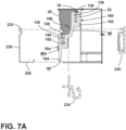
- the RC foam gasket 30a may be coupled to the side surface 46a of the trim breaker assembly 22, as shown in FIGS. 7A and 9A .
- the RC foam gasket 30b may be coupled to the outer surface 44a of the trim breaker assembly 22, as shown in FIGS. 7B and 9B .
- the RC foam gasket 30c may be coupled to the inner surface 48a, as shown in FIGS. 7C and 9C .
- the trim breaker assembly 22 may include two RC foam gaskets 30 coupled to the respective surfaces 32.
- the first RC foam gasket 30a may be coupled to the side surface 46a and the third RC foam gasket 30c may be coupled to the inner surface 48a.
- the trim breaker assembly 22 may also include the first RC foam gasket 30a, the second RC foam gasket 30b, and the third RC foam gasket 30c coupled to the respective surfaces 32.
- the second cross-sectional profile 182 includes an outside wall 200 that defines the side surface 46b.
- a wrapper channel wall 192 is coupled or connected to the outside wall 200.
- the wrapper channel wall 202 extends away from and then parallel to the outside wall 200 to define the wrapper channel 138a therebetween.
- the outside wall 200 also includes the outer surface 44b defined on a distal end of 204 of the outside wall 200 that extends away from the wrapper channel 138a.
- the side surface 46b is generally adjacent to and perpendicular to the outer surface 44b.
- An inner wall 206 is coupled to the wrapper channel wall 202 and extends and connects to a liner channel wall 208 that defines the liner channel 138b.
- the wrapper channel 138a may be offset from the liner channel 138b.
- the inner wall 206, the outside wall 200, and the wrapper channel wall 202 define a receiving recess 210 to couple to a freezer compartment (FC) trim breaker adapter 212.
- the inner wall 206 and the wrapper channel wall 202 may define the inner surface 48b within the receiving recess 210.
- the inner surface 48b is not limited to the surface defined by the inner wall 206 and the wrapper channel wall 202.
- the inner surface 48b may extend along the inner wall 206 within the receiving recess 210 or along the inner wall 206 opposing the insulation cavity 80.
- the FC foam gasket 34 is coupled to and extends along at least one of the outer surface 44b, the side surface 46b, and the inner surface 48b (i.e., at least one of the surfaces 32).
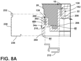
- the FC foam gasket 34a may be coupled to the side surface 46b of the trim breaker assembly 22, as shown in FIGS. 8A and 10A .
- the FC foam gasket 34b may be coupled to the outer surface 44a of the trim breaker assembly 22, as shown in FIGS. 8B and 10B .
- the FC foam gasket 34c may be coupled to the inner surface 48a, as shown in FIGS. 8C and 10C .
- the trim breaker assembly 22 may include two FC foam gaskets 34 coupled to the respective surfaces 32.
- first FC foam gasket 34a may be coupled to the side surface 46a and the third FC foam gasket 34c may be coupled to the inner surface 48a.
- the trim breaker assembly 22 may also include the first FC foam gasket 34a, the second FC foam gasket 34b, and the third FC foam gasket 34c coupled to the respective surfaces 32.
- the side surface 46 may extend between the first cross-sectional profile 180 and the second cross-sectional profile 182 allowing the foam gaskets 30, 34 to be coupled and extend therebetween.
- the first and second ends 36, 40 of the cross member 140 may be flush with the outside walls 190, 200 creating the continuous side surface 46 extending along the perimeter 162 of the cabinet 12.
- the side surface 46 may extend along the recessed portions 164a, 164b on the first and second ends 36, 40 of the cross member 140.
- the foam gaskets 30, 34 may be coupled to the side surface through the recessed portions 164a, 164b.
- the side surface 46 is not limited to extending along the first and second ends 36, 40 of the cross member 140 and may extend along the first cross-sectional profile 180 and/or second cross-sectional profile 182 of the trim breaker assembly 22 with gaps at the mullion region 28.
- the outer surface 44 may extend between the first cross-sectional profile 180 and the second cross-sectional profile 182 through the mullion region 28 of the trim breaker assembly 22.
- the cross member 140 may include raised portions that extend between the distal ends 194, 204 of the outside walls 190, 200.
- the outer surface 44 may extend across the raised portions allowing the foam gaskets 30, 34 to extend between the first and second cross-sectional profiles 180, 182.
- the distal the distal ends 194, 204 of the outside walls 190, 200 may be flush or substantially flush with the cross member 140 thereby allowing the outer surface 44 to extend across the mullion region 28.
- the inner surfaces 48a, 48b may extend around the perimeters 24, 26 of the compartments 14, 16.
- the inner surface 48a, 48b may create continuous surfaces along the first and second cross-sectional profiles 180, 182.
- the inner surfaces 48a, 48b may extend between the first cross-sectional profile 180 and the second cross-sectional profile 182 through the mullion region 28 of the trim breaker assembly 22.
- the cross member 140 may define a groove or a raised portion to connect the inner surfaces 48a, 48b.
- the inner surfaces 48a, 48b may be flush or substantially flush with the cross member 140, thereby allowing the inner surface 48 to extend across the mullion region 28.
- first cross-sectional profile 180 and the second cross-sectional profile 182 may be the same profile around each of the compartments 14, 16.
- the first cross-sectional profile 180 and second cross-sectional profile 182 are not limited to the configurations described and may be configured to include at least one of the surfaces 32 to allow the at least one of the foam gaskets 30, 34 to couple thereto.
- the engagement members 50 are configured to couple to the trim breaker assembly 22 and compress at least one of the RC foam gasket 30 and the FC foam gasket 34.
- the engagement member 50 may engage the trim breaker assembly 22 and compress both the RC foam gaskets 30 and the FC foam gaskets 34.
- the compressed RC foam gasket 30 and FC foam gasket 34 define the RC seal 52 and the FC seal 54, respectively, between the trim breaker assembly 22 and the engagement member 50.
- the engagement member 50 may compress the RC foam gasket 30 along the full portion 38 of the perimeter 24 of the refrigerator compartment 14.
- the engagement member 50 may also compress the FC foam gasket 34 along the full portion 42 of the perimeter 26 of the freezer compartment 16.
- the engagement members 50 generally include an engagement surface 228 to engage or compress the foam gaskets 30, 34.
- the engagement member 50 may compress portions of the foam gaskets 30, 34 to form the seal around the compartments 14, 16 or the cabinet 12.
- the engagement member 50 may compress a portion of the RC foam gasket 30 along the portion 38 of the perimeter 24 of the refrigerator compartment 14.
- the engagement member may also compress a portion of the FC foam gasket 34 along the portion 42 of the perimeter 26 of the freezer compartment 16.
- the FC foam gasket 34 coupled to the portion 42 of the perimeter 26 of the freezer compartment 16 may be compressed along the first and second segments 150a, 150b.
- the FC foam gasket 34 disposed in the lower gap 144 may be uncompressed or partially compressed by the engagement member 50. This configuration may be advantageous for routing the heat loop 146 through the lower gap 144 without the FC foam gasket 34 substantially impinging on the heat loop 146.
- the engagement member 50 may include one gap or multiple gaps in the engagement surface 228 or recessed portions relative to the engagement surface 228.
- the recessed portions or gaps may not compress or partially compress the gaskets 30, 34.
- the engagement surface 228 may also not compress or fully compress the gaskets 30, 34 when the surfaces 32 include recessed portions, as discussed herein.
- the engagement members 50 may include or be configured as at least one of the FC trim breaker adapter 212, a light assembly 230, a trim breaker cover 232, also referred to as a cover 232, and a refrigerator compartment (RC) trim breaker adapter 234. Each of the engagement members is configured to couple to the trim breaker assembly 22.
- the trim breaker cover 232 is generally configured to couple to the trim breaker assembly 22 along the perimeter 162 of the cabinet 12.
- the trim breaker cover 232 includes an outside wall 236 and a side wall 238, which generally form an L-shape.
- the outside wall 236 may extend proximate to or over the outer surface 44, and the side wall 238 may extend proximate to or over the side surface 46 of the trim breaker assembly 22 when the cover 232 is coupled thereto.
- the trim breaker cover 232 may also include a cross member portion 240 that corresponds to the cross member 140 and the mullion region 28 when coupled to the trim breaker assembly 22.
- the trim breaker cover 232 may extend along the perimeters 24, 26 of the refrigerator and freezer compartments 14, 16.
- the outside wall 236 and/or the side wall 238 may include the engagement surface 228 to compress the foam gaskets 30, 34 to define the seals 52, 54.
- the outside wall 236 and/or the side wall 238 may be configured to engage the foam gaskets 30, 34 to define the seals 52, 54 along both the portions 38, 42 of the perimeter 24, 26.
- the cover 232 may be configured to engage one of either the foam gasket 30 along the perimeter 24 of the refrigerator compartment 14 and the foam gasket 34 along the perimeter 26 of the freezer compartment 16.
- the foam gaskets 30, 34 disposed on the side surface 46, as shown in FIGS. 7A and 8A , and/or the outer surface 44, as shown in FIGS. 7B and 8B are in an expanded or uncompressed state.
- the foam gaskets 30, 34 disposed on the side surface 46, as shown in FIGS. 9A and 10A , and/or the outer surface 44, as shown in FIGS. 9B and 10B are in a compressed state and define the seals 52, 54.
- the seals 52,54 defined between the trim breaker assembly 22 and the cover 232 reduce or prevent air infiltration from outside the cabinet 12, between the trim breaker assembly 22 and the engagement member 50, and to the compartments 14, 16.
- the light assembly 230 is generally configured to couple to the trim breaker assembly 22 along the perimeter 24 of the refrigerator compartment 14.
- the light assembly 230 is configured to selectively provide light to the refrigerator compartment 14.
- the light assembly 230 may provide light to the refrigerator compartment 14 when the first insulated door 70a is open.
- the light assembly 230 may include a housing 250, a light source 252, and a lens portion 254.
- the housing 250 is configured to couple the light assembly 250 to the trim breaker assembly 22.
- the light source 252 is configured to provide the light to the refrigerator compartment 14 and may be a Light Emitting Diode (LED) or other light sources.
- the lens portion 254 is configured to disperse the light produced by the light source 252 throughout the refrigerator compartment 14.
- the light assembly 230 generally includes the engagement surface 228 on the housing 250 to compress the foam gasket 30c.
- the light assembly 230 may be coupled to the trim breaker assembly 22 along the portion 38 of the perimeter 24.
- the light assembly 230 may also be coupled to the trim breaker assembly 22 along the full perimeter 24 of the refrigerator compartment 14.
- the foam gasket 30c is in an expanded or uncompressed state.
- the foam gasket 30c is in a compressed state defining the seal 52 between the trim breaker assembly 22 and the light assembly 230.
- the light assembly 230 is generally configured to couple to the first cross-sectional profile 180 of the trim breaker assembly 22 but is not limited to such configurations.
- the light assembly 230, or an additional lighting assembly 230 may be configured to couple to the second cross-sectional profile 182 to illuminate the freezer compartment 16 without departing from the teachings herein.
- the foam gasket 30c disposed on the inner surface 48 may be configured to be compressed by the RC trim breaker adapter 234.
- the RC trim breaker adapter 234 may be configured to couple the heat loop 146, the light assembly 230, or other components to the first cross-sectional profile 180 of the trim breaker assembly 22.
- the RC trim breaker adapter 234 when coupled to the trim breaker assembly 22 may compress the foam gasket 30c to define the seal 52 between the trim breaker assembly 22 and the RC trim breaker adapter 234.
- the RC trim breaker adapter 234 may be configured similarly to the FC trim breaker adapter 212, as discussed further herein.
- the FC trim breaker adapter 212 is generally configured to engage and couple with the trim breaker assembly 22.
- the FC trim breaker adapter 212 may be configured to couple the heat loop 146 of other components to the second cross-sectional profile 182 of the trim breaker assembly 22.
- the FC trim breaker adapter 212 may couple to the trim breaker assembly 22 by engaging the receiving recess 210 of the trim breaker assembly 22.
- the FC trim breaker adapter 212 may extend along the portion 42 of the perimeter 26 of the freezer compartment 16.
- the FC trim breaker adapter 212 may also extend along the full perimeter 26 of the freezer compartment 16.
- the foam gasket 34c disposed on the inner surface 48 is in an expanded or uncompressed state.
- the foam gasket 34c disposed on the inner surface 48 is in a compressed state defining the seal 54 between the FC trim breaker adapter 212 and the trim breaker assembly 22.
- the foam gaskets 30, 34 are applied to the surface 32 or surfaces 32 of the trim breaker assembly 22 using a foam nozzle 270 configured to be adjusted around the perimeters 24, 26 of the compartments 14, 16 and/or the perimeter 162 of the cabinet 12.
- the foam nozzle 270 may be coupled to a linear robot or other machines that are configured to move the foam nozzle 270 along a defined path 272.
- the foam nozzle 270 may be routed around the defined path 272 to apply the foam gaskets 30, 34 to the surfaces 32 of the trim breaker assembly 22 and along the perimeters 24, 26 or portions 38, 42 of the perimeters 24, 26 of the compartments 14, 16.
- the foam gaskets 30, 34 are applied directly to the surfaces 32 from the foam nozzle 270.
- the foam gaskets 30, 34 may be applied in a continuous or a non-continuous manner.
- the foam gasket 30 may be applied along the portion 38 of the perimeter 24 without breaks in the foam gaskets 30, 34.
- the continuous foam gasket 30 may assist in preventing air intrusion between the trim breaker assembly 22 and the engagement member 50.
- the foam gasket 34 may be applied along the portion 42 of the perimeter 26 with a gap corresponding to the lower gap 144 of the trim breaker assembly 22.
- the non-continuous foam gasket 34 may assist in preventing air intrusion between the trim breaker assembly 22 and the engagement member 50 while also maximizing the efficiency of the manufacturing process. Both the continuous and non-continuous laying of the foam gaskets 30, 34 may be used while laying the foam gaskets 30, 34 on the trim breaker assembly 22.
- the foam gaskets 30, 34 are generally dispensed in an uncured state and undergo a curing process resulting in a cured state.
- the foam gaskets 30, 34 may be a liquid, a fluid, or a semi-solid where the foam gaskets 30, 34 may be directed to a specific location through the foam nozzle 270.
- the foam gaskets 30, 34 In the uncured state the foam gaskets 30, 34 have not undergone the curing process or have partially undergone the curing process.
- the foam gaskets 30, 34 may undergo the curing process as it is dispensed by the foam nozzle 270 causing the surface of the foam gaskets 30, 34 to cure preventing the foam gaskets 30, 34 from flowing off the surface 32 of the trim breaker assembly 22.
- the foam gaskets 30, 34 may have a high-surface tension to reduce or prevent the flow of the foam gaskets 30, 34 in the uncured state.
- the foam gaskets 30, 34 In the cured state the foam gaskets 30, 34 are generally set as a solid or semi-solid, and the curing process has substantially completed (i.e., the chemical reaction has completed or reached an equilibrium).
- the foam gaskets 30, 34 may undergo the curing process once introduced to an atmosphere or being subject to an activated curing process, such as using light (i.e., ultraviolet light) or introducing a catalyst.
- the foam gaskets 30, 34 may be a two-part mix where the curing process begins when a first component and a second component are mixed, causing a chemical reaction to begin.
- the foam gaskets 30, 34 may expand during the curing process to provide for an open cell structure, a closed cell structure, or a mixed cell structure (i.e., a mix of an open cell structure and a closed cell structure) in the cured state.
- the foam gaskets 30, 34 may form the structure by producing a gas as a byproduct of the chemical reaction.
- a gas may also be introduced while dispensing the foam gaskets 30, 34 when the chemical reaction does not produce or produce enough gas as a byproduct to create the desired structure.
- the gas introduced or formed as a byproduct may foam up the foam gaskets 30, 34 to from the open cells structure, the closed cell structure, or the mixed cell structure.
- the foam gaskets 30, 34 may include two components, a polyol, which may be a polyurethane polyol, and an isocyanate.
- the foam gaskets 30, 34 may be a polyurethane foam that includes a polyurethane polyol and an isocyanate in the uncured state.
- the foam gaskets 30, 34 may adhere to the trim breaker assembly 22.
- the foam gaskets 30, 34 may chemically react with the trim breaker assembly 22 creating a chemical bond and/or mechanically couple to the trim breaker assembly 22.
- the foam gaskets 30, 34 generally cure to a soft foam state allowing for the foam gaskets 30, 34 to be compressed while also providing an outward biasing force to maintain an engagement with the compressing engagement member 50.
- the foam gaskets 30, 34 are uncompressed and coupled to the surface 32 of the trim breaker assembly 22.
- the foam gaskets 30, 34 may be compressed by the engagement member 50, as illustrated in FIG. 11C , to create the seals 52, 54.
- the foam gaskets 30, 34 when compressed, close any open cell structures and prevent or reduce air infiltration therethrough.
- the engagement member 50 may be coupled to the trim breaker assembly 22 when the foam gaskets 30, 34 are in the uncured state.
- the foam gaskets 30, 34 may cure and mechanically or chemically adhere to the engagement member 50.
- a flow diagram of a method 300 for manufacturing the vacuum insulated structure including at least one of the RC foam gasket 30 and the FC foam gasket 34 is illustrated.
- the method includes step 304 of providing the cabinet 12 including the insulation cavity 80 and having at least one of the refrigerator compartment 14 or the freezer compartment 16.
- the cabinet 12 includes the trim breaker assembly 22 that extends along the perimeter 24, 26 of the at least one compartment 14, 16.
- the at least partial vacuum 90 is drawn in the insulation cavity 80.
- the partial vacuum 90 may be a predetermined pressure.
- step 312 at least one of the foam gaskets 30, 34 is applied to the trim breaker assembly 22.
- Step 312 may also include applying both foam gaskets 30, 34 to the trim breaker assembly 22.
- the foam gaskets 30, 34 may be applied to the portions 38, 42 of the perimeters 24, 26 of the compartments 14, 16, respectively.
- the at least one foam gasket 30, 34 may also include one or more of the plurality of RC foam gaskets 30a-30c and/or one or more the plurality of FC foam gaskets 34a-34c.
- the engagement member 50 is coupled to the trim breaker assembly 22 to compress the foam gaskets 30, 34 to define the seals 52, 54.
- the seals 52, 54 reduce air infiltration between the engagement member 50 and the trim breaker assembly 22.
- the steps of the method 300 may be performed in any order, simultaneously, concurrently, repeated, omitted, etc. without departing from the teachings herein.
- the foam gaskets 30, 34 assist in reducing or preventing air infiltration between the engagement member 50 and the trim breaker assembly 22.
- the foam gaskets 30, 34 form the seals 52, 54 when compressed by the engagement member 50.
- the seals 52, 54 may reduce air infiltration from outside the cabinet to the compartments 14, 16.
- the seals 52, 54 fill any gap that may be present between the trim breaker assembly 22 and the engagement member 50.
- the reduced air infiltration may assist in reducing the amount of heat transfer from the local environment outside the appliance 10 and the inside of the appliance 10 and may assist in maximizing energy efficiency.
- the foam gaskets 30, 34 being laid by the foam nozzle 270 may also allow for the seals 52, 54 to be continuous or have minimized joints or gaps along the portions 38, 42 of the perimeters 24, 26, thereby maximizing the reduction of air infiltration.
- the foam nozzle 270 may also increase efficiency in the manufacturing process of the appliance 10 by forming the foam gaskets 30, 34 directly on the trim breaker assembly 22. Additional benefits or advantages may be realized and/or achieved.
- the device disclosed herein is further summarized in the following paragraphs and is further characterized by combinations of any and all of the various aspects described herein.
- a vacuum insulated refrigerator includes a cabinet defining a refrigerator compartment.
- the cabinet includes a liner, a wrapper, and a trim breaker assembly coupled to the liner and the wrapper.
- the trim breaker assembly extends along a perimeter of the refrigerator compartment.
- the trim breaker assembly includes a mullion region.
- At least one foam gasket is coupled to at least one surface of the trim breaker assembly.
- the at least one foam gasket is routed from a first end of the mullion region, along a portion of the perimeter of the refrigerator compartment, and to a second end of the mullion region.
- the at least one surface of the trim breaker assembly is at least one of an outer surface, a side surface, and an inner surface.
- At least one engagement member is configured to couple to the trim breaker assembly and define a seal by compressing the at least one foam gasket between the at least one engagement member and the trim breaker assembly.
- At least one engagement member is at least one of a cover extending around a perimeter of a cabinet and includes an outside wall and a side wall, where the outside wall extends over an outer surface of a trim breaker assembly and the side wall extends over a side surface of the trim breaker assembly, and a light assembly coupled to a trim breaker assembly along at least a portion of a perimeter of a refrigerator compartment and to selectively illuminate the refrigerator compartment.
- At least one foam gasket extends along an outer surface of a trim breaker assembly.
- At least one engagement member includes a cover, where an outside wall of the cover compresses the at least one foam gasket to define a seal.
- At least one foam gasket extends along a side surface of a trim breaker assembly.
- At least one engagement member includes a cover, where a side wall of the cover compresses the at least one foam gasket to define a seal.
- At least one foam gasket extends along an inner surface.
- At least one engagement member includes a light assembly, where the light assembly compresses the at least one foam gasket to define a seal.
- a cabinet further defines a freezer compartment and a trim breaker assembly extends along a perimeter of the freezer compartment.
- At least one foam gasket includes a refrigerator compartment foam gasket coupled to at least one surface of the trim breaker assembly.
- the refrigerator compartment foam gasket is routed from a first end of a mullion region, along a portion of a perimeter of a refrigerator compartment, and to a second end of the mullion region.
- a freezer compartment foam gasket is coupled to the at least one surface of the trim breaker assembly.
- the freezer compartment foam gasket is routed from the first end of the mullion region, along a portion of the perimeter of the freezer compartment, and to the second end of the mullion region.
- At least one engagement member is at least one of a cover extending along a perimeter of a cabinet and including an outside wall and a side wall, where the outside wall extends over an outer surface of a trim breaker assembly and the side wall extends over a side surface of the trim breaker assembly, a light assembly coupled to a trim breaker assembly along at least a portion of a perimeter of a refrigerator compartment and configured to selectively illuminate a refrigerator compartment, and a trim breaker adapter coupled to the trim breaker assembly along at least a portion of a perimeter of a freezer compartment.
- each of a refrigerator compartment foam gasket and a freezer compartment foam gasket extends along a side surface of a trim breaker assembly.
- At least one engagement member includes a cover, where a side wall of the cover compresses the refrigerator compartment foam gasket and the freezer compartment foam gasket to define a seal.
- At least one foam gasket is a polyurethane foam.
- a vacuum insulated appliance includes a structural wrapper defining a freezer compartment.
- a trim breaker assembly is coupled to the structural wrapper.
- An insulation cavity is defined between the structural wrapper and the trim breaker assembly.
- the trim breaker assembly defines a perimeter of the freezer compartment and includes a mullion region.
- At least one foam gasket is coupled to at least one surface of the trim breaker assembly.
- the at least one foam gasket is routed from a first end of the mullion region, along a portion of the perimeter of the freezer compartment, and to a second end of the mullion region.
- the at least one surface of the trim breaker assembly includes at least one of an outer surface, a side surface, and an inner surface.
- At least one engagement member is coupled to the trim breaker assembly and define a seal by compressing the at least one foam gasket between the at least one engagement member and the trim breaker assembly to reduce air infiltration into the freezer compartment.
- At least one engagement member is at least one of a cover extends along a perimeter of the cabinet and including an outside wall and a side wall, where the outside wall extends over an outer surface of a trim breaker assembly and the side wall extends over a side surface of the trim breaker assembly, and a trim breaker adapter coupled to the trim breaker assembly along at least the portion of a perimeter of a freezer compartment.
- At least one foam gasket extends along an outer surface of a trim breaker assembly.
- At least one engagement member includes a cover, where an outside wall of the cover compresses at least one foam gasket to define a seal.
- At least one foam gasket extends along a side surface of a trim breaker assembly.
- At least one engagement member includes a cover, where a side wall of the cover compresses the at least one foam gasket to define a seal.
- At least one foam gasket extends along an inner surface of a trim breaker assembly.
- At least one engagement member includes a trim breaker adapter, where the trim breaker adapter compresses the at least one foam gasket to define a seal.
- At least one foam gasket includes a first segment extending along a portion of a perimeter of a freezer compartment from a first end of a mullion region to a gap defined by a trim breaker assembly, and a second segment extending along the portion of the perimeter the freezer compartment from the gap to a second end of the mullion region.
- a method for manufacturing a vacuum insulated structure includes providing a cabinet defining an insulation cavity and forming at least one compartment, the cabinet including a trim breaker assembly that extends along a perimeter of the at least one compartment, drawing an at least partial vacuum within the insulating cavity, applying at least one foam gasket to at least one surface of the trim breaker assembly along at least a portion of the perimeter of the at least one compartment, and coupling at least one engagement member with the trim breaker assembly to compress the at least one foam gasket therebetween and define a seal to reduce air infiltration between the at least one engagement member and the trim breaker assembly into the at least one compartment.
- a method includes applying at least one foam gasket to at least one surface of a trim breaker assembly includes applying a first foam gasket of the at least one foam gasket to an outer surface of the at least one surface of the trim breaker assembly along a portion of a perimeter of at least one compartment, and applying a second foam gasket of the at least one foam gasket to an inner surface of the at least one surface of the trim breaker assembly along the portion of the perimeter of the at least one compartment.
- At least one engagement member includes a cover and a light assembly
- a method includes coupling the at least one engagement member with a trim breaker assembly to compress at least one foam gasket includes coupling the cover with the trim breaker assembly to compress a first foam gasket between the cover and an outer surface, and coupling the light assembly with the trim breaker assembly to compress a second foam gasket between the light assembly and an inner surface.
- a method includes applying at least one foam gasket to at least one surface of a trim breaker assembly includes applying a first foam gasket of the at least one foam gasket to the at least one surface of the trim breaker assembly along a portion of a perimeter of a first compartment of at least one compartment, and applying a second foam gasket of at least one foam gasket to the at least one surface of the trim breaker assembly along a portion of a perimeter of a second compartment of the at least one compartment.
- At least one engagement member includes a cover
- a method includes coupling the at least one engagement member with a trim breaker assembly to compress at least one foam gasket therebetween includes coupling the cover to the trim breaker assembly to compress a first foam gasket and a second foam gasket between the trim breaker assembly and the cover.
- the term "coupled” in all of its forms, couple, coupling, coupled, etc. generally means the joining of two components (electrical or mechanical) directly or indirectly to one another. Such joining may be stationary in nature or movable in nature. Such joining may be achieved with the two components (electrical or mechanical) and any additional intermediate members being integrally formed as a single unitary body with one another or with the two components. Such joining may be permanent in nature or may be removable or releasable in nature unless otherwise stated.
Landscapes
- Engineering & Computer Science (AREA)
- Chemical & Material Sciences (AREA)
- Combustion & Propulsion (AREA)
- Physics & Mathematics (AREA)
- Mechanical Engineering (AREA)
- Thermal Sciences (AREA)
- General Engineering & Computer Science (AREA)
- Refrigerator Housings (AREA)
Abstract
A vacuum insulated refrigerator (10) includes a cabinet (12) defining a refrigerator compartment (14). The cabinet (12) includes a liner (18), a wrapper (20), and a trim breaker assembly (22) coupled to the liner (18) and the wrapper (20). The trim breaker assembly (22) extends along a perimeter (24) of the refrigerator compartment (14) and includes a mullion region (28). At least one foam gasket (30, 30a-30c, 34, 34a-34c) is coupled to at least one surface (32, 44, 44a, 44b, 46, 46a, 46b, 48, 48a, 48b) of the trim breaker assembly (22) and is routed from a first end (36) of the mullion region (28), along a portion of the perimeter (24) of the refrigerator compartment (14), and to a second end (40) of the mullion region (28). The at least one surface (32, 44, 44a, 44b, 46, 46a, 46b, 48, 48a, 48b) of the trim breaker assembly (22) is at least one of an outer surface (44, 44a), a side surface (46, 46a), and an inner surface (48, 48a). At least one engagement member (50, 212, 230, 232, 234) is coupled to the trim breaker assembly (22) to define a seal (52, 52a-52c, 54, 54a-54c) by compressing the at least one foam gasket (30, 30a-30c, 34, 34a-34c) therebetween.
Description
- The present disclosure generally relates to a trim breaker interface formed by a foam gasket coupled to a trim breaker assembly, and more specifically, to a foam gasket coupled to a trim breaker assembly to define a seal for a vacuum insulated appliance and reduce air infiltration.
- According to an aspect of the present disclosure, a vacuum insulated refrigerator includes a cabinet defining a refrigerator compartment. The cabinet includes a liner, a wrapper, and a trim breaker assembly coupled to the liner and the wrapper. The trim breaker assembly extends along a perimeter of the refrigerator compartment. The trim breaker assembly includes a mullion region. At least one foam gasket is coupled to at least one surface of the trim breaker assembly. The at least one foam gasket is routed from a first end of the mullion region, along a portion of the perimeter of the refrigerator compartment, and to a second end of the mullion region. The at least one surface of the trim breaker assembly is at least one of an outer surface, a side surface, and an inner surface. At least one engagement member is configured to couple to the trim breaker assembly and define a seal by compressing the at least one foam gasket between the at least one engagement member and the trim breaker assembly.
- According to another aspect of the present disclosure, a vacuum insulated appliance includes a structural wrapper defining a freezer compartment. A trim breaker assembly is coupled to the structural wrapper. An insulation cavity is defined between the structural wrapper and the trim breaker assembly. The trim breaker assembly defines a perimeter of the freezer compartment and includes a mullion region. At least one foam gasket is coupled to at least one surface of the trim breaker assembly. The at least one foam gasket is routed from a first end of the mullion region, along a portion of the perimeter of the freezer compartment, and to a second end of the mullion region. The at least one surface of the trim breaker assembly includes at least one of an outer surface, a side surface, and an inner surface. At least one engagement member is coupled to the trim breaker assembly and define a seal by compressing the at least one foam gasket between the at least one engagement member and the trim breaker assembly to reduce air infiltration into the freezer compartment.
- According to yet another aspect of the present disclosure, a method for manufacturing a vacuum insulated structure includes providing a cabinet defining an insulation cavity and forming at least one compartment, the cabinet including a trim breaker assembly that extends along a perimeter of the at least one compartment, drawing an at least partial vacuum within the insulating cavity, applying at least one foam gasket to at least one surface of the trim breaker assembly along at least a portion of the perimeter of the at least one compartment, and coupling at least one engagement member with the trim breaker assembly to compress the at least one foam gasket therebetween and define a seal to reduce air infiltration between the at least one engagement member and the trim breaker assembly into the at least one compartment.
- These and other features, advantages, and objects of the present disclosure will be further understood and appreciated by those skilled in the art by reference to the following specification, claims, and appended drawings.
- In the drawings:
-
FIG. 1 is a front perspective of a refrigeration appliance, according to the present disclosure; -
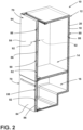
FIG. 2 is a cross-sectional view of a refrigeration appliance with a vacuum insulated cabinet and vacuum insulated doors, according to the present disclosure; -
FIG. 3 is a front perspective of a cabinet for a refrigeration appliance with a trim breaker cover, according to the present disclosure; -
FIG. 4 is a side perspective view of a refrigeration appliance, according to the present disclosure; -
FIG. 5 is an exploded side perspective view of a cabinet for a refrigeration appliance with a wrapper, a liner, a trim breaker assembly, and engagement members to engage the trim breaker assembly, according to the present disclosure ; -
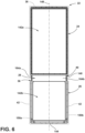
FIG. 6 is a front elevational view of the trim breaker ofFIG. 5 , according to the present disclosure; -
FIG. 7A is a partially exploded and partial cross-sectional view of the cabinet ofFIG. 3 taken along lines VII-VII, illustrating a trim breaker assembly, engagement members, and a foam gasket on a side surface of the trim breaker assembly, according to the present disclosure; -
FIG. 7B is a partially exploded and partial cross-sectional view of a cabinet of a refrigeration appliance, illustrating a trim breaker assembly, engagement members, and a foam gasket on an outer surface of the trim breaker assembly, according to the present disclosure; -
FIG. 7C is a partially exploded and partial cross-sectional view of a cabinet of a refrigeration appliance, illustrating a trim breaker assembly, engagement members, and a foam gasket on an inner surface of the trim breaker assembly, according to the present disclosure; -
FIG. 8A a partially exploded and partial cross-sectional view of the cabinet ofFIG. 3 taken along lines VIII-VIII, illustrating a trim breaker assembly, engagement members, and a foam gasket on a side surface of the trim breaker assembly, according to the present disclosure; -
FIG. 8B is a partially exploded and partial cross-sectional view of a cabinet of a refrigeration appliance, illustrating a trim breaker assembly, engagement members, and a foam gasket on an outer surface of the trim breaker assembly, according to the present disclosure; -
FIG. 8C is a partially exploded and partial cross-sectional view of a cabinet of a refrigeration appliance, illustrating a trim breaker assembly, engagement members, and a foam gasket on an inner surface of the trim breaker assembly, according to the present disclosure; -
FIG. 9A is a partial cross-sectional view of the cabinet ofFIG. 3 taken along VII-VII, illustrating a trim breaker assembly coupled to engagement members compressing a foam gasket on a side surface of the trim breaker assembly, according to the present disclosure; -
FIG. 9B is a partial cross-sectional view of a cabinet of a refrigeration appliance, illustrating a trim breaker assembly coupled to engagement members compressing a foam gasket on an outer surface of the trim breaker assembly, according to the present disclosure; -
FIG. 9C is a partial cross-sectional view of a cabinet of a refrigeration appliance, illustrating a trim breaker assembly coupled to engagement members compressing a foam gasket on an inner surface of the trim breaker assembly, according to the present disclosure; -
FIG. 10A is a partial cross-sectional view of the cabinet ofFIG. 3 taken along lines VIII-VIII, illustrating a trim breaker assembly coupled to engagement members compressing a foam gasket on a side surface of the trim breaker assembly, according to the present disclosure; -
FIG. 10B is a partial cross-sectional view of a cabinet of a refrigeration appliance, illustrating a trim breaker assembly coupled to engagement members compressing a foam gasket on an outer surface of the trim breaker assembly, according to the present disclosure; -
FIG. 10C is a partial cross-sectional view of a cabinet of a refrigeration appliance, illustrating a trim breaker assembly coupled to engagement members compressing a foam gasket on an inner surface of the trim breaker assembly, according to the present disclosure; -
FIG. 11A is a schematic elevational view of a foam gasket being applied to a trim breaker assembly with a foam nozzle, according to the present disclosure; -
FIG. 11B is a schematic elevational view of a foam gasket applied to a trim breaker assembly, according to the present disclosure; -
FIG. 11C is a schematic elevational view of a compressed foam gasket between a trim breaker assembly and an engagement member, according to the present disclosure; and -
FIG. 12 is a flow diagram of a method of manufacturing a vacuum insulated structure, according to the present disclosure. - The components in the figures are not necessarily to scale, emphasis instead being placed upon illustrating the principles described herein.
- The present illustrated embodiments reside primarily in combinations of method steps and apparatus components related to a foam gasket coupled to a trim breaker assembly. Accordingly, the apparatus components and method steps have been represented, where appropriate, by conventional symbols in the drawings, showing only those specific details that are pertinent to understanding the embodiments of the present disclosure so as not to obscure the disclosure with details that will be readily apparent to those of ordinary skill in the art having the benefit of the description herein. Further, like numerals in the description and drawings represent like elements.
- For purposes of description herein, the terms "upper," "lower," "right," "left," "rear," "front," "vertical," "horizontal," and derivatives thereof shall relate to the disclosure as oriented in
FIG. 1 . Unless stated otherwise, the term "front" shall refer to the surface of the element closer to an intended viewer, and the term "rear" shall refer to the surface of the element further from the intended viewer. However, it is to be understood that the disclosure may assume various alternative orientations, except where expressly specified to the contrary. It is also to be understood that the specific devices and processes illustrated in the attached drawings, and described in the following specification are simply exemplary embodiments of the inventive concepts defined in the appended claims. Hence, specific dimensions and other physical characteristics relating to the embodiments disclosed herein are not to be considered as limiting, unless the claims expressly state otherwise. - The terms "including," "comprises," "comprising," or any other variation thereof, are intended to cover a non-exclusive inclusion, such that a process, method, article, or apparatus that comprises a list of elements does not include only those elements but may include other elements not expressly listed or inherent to such process, method, article, or apparatus. An element preceded by "comprises a ... " does not, without more constraints, preclude the existence of additional identical elements in the process, method, article, or apparatus that comprises the element.
- Referring to
FIGS. 1-12 ,reference numeral 10 generally designates a vacuum insulated structure including acabinet 12 defining at least one compartment, often including arefrigerator compartment 14 and afreezer compartment 16. Thecabinet 12 includes aliner 18, awrapper 20, and atrim breaker assembly 22 coupled to theliner 18 and thewrapper 20. Thetrim breaker assembly 22 extends along aperimeter 24 of therefrigerator compartment 14 and aperimeter 26 of thefreezer compartment 16, and thetrim breaker assembly 22 includes amullion region 28. At least one refrigerator compartment (RC) foam gasket 30, which may includeRC foam gaskets 30a-30c that are collectively referred to herein as the RC foam gaskets 30, is coupled to at least onesurface 32 of thetrim breaker assembly 22. At least one freezer compartment (FC) foam gasket 34, which may includeFC foam gaskets 34a-34c that are collectively referred to herein as the FC foam gaskets 34, is coupled to the at least onesurface 32 of thetrim breaker assembly 22. The RC foam gaskets 30 and FC foams gaskets 34 may also be referred to as the foam gaskets 30, 34. - The RC foam gasket 30 is routed from a
first end 36 of themullion region 28, along aportion 38 of theperimeter 24 of therefrigerator compartment 14, and to asecond end 40 of themullion region 28. The FC foam gasket 34 is routed from thefirst end 36 of themullion region 28, along aportion 42 of theperimeter 26 of thefreezer compartment 16, and to thesecond end 40 of themullion region 28. The at least onesurface 32 of thetrim breaker assembly 22 is at least one of anouter surface 44, which may include a firstouter surface 44a and a secondouter surface 44b, aside surface 46, which may include afirst side surface 46a and asecond side surface 46b, and aninner surface 48, which may include a firstinner surface 48b and a secondinner surface 48b. Thefirst surfaces refrigerator compartment 14 and thesecond surfaces freezer compartment 16. - At least one
engagement member 50, which may include a plurality ofengagement members 50, is configured to couple to thetrim breaker assembly 22 to define at least one of a refrigerator compartment (RC) seal 52 by compressing the RC foam gasket 30. The RC seal 52 may include RC seals 52a-52c, which may be collectively referred to as the RC seals 52. Additionally, the at least oneengagement member 50 is configured to couple to thetrim breaker assembly 22 to define at least one freezer compartment (FC) seal 54 by compressing the FC foam gasket 34. The FC seal 54 may include FC seals 54a-54c, which may be collectively referred to as FC seals 54. - Referring still to
FIGS. 1-4 , the vacuum insulatedappliance 10 is illustrated as a refrigeration appliance. Therefrigeration appliance 10 is illustrated as a bottom-mount refrigerator having an upper compartment configured as therefrigerator compartment 14 and a lower compartment configured as thefreezer compartment 16. - The
cabinet 12 of the illustratedrefrigeration appliance 10 includes a firstinsulated door 70a and a secondinsulated door 70b. The firstinsulated door 70a and the secondinsulated door 70b, which can collectively be referred to asinsulated doors 70, can have substantially similar configurations, as discussed further herein. In this way, the refrigerator andfreezer compartments cabinet 12 can be sealed with theinsulated doors appliance 10 may include thecabinet 12 defining at least a first compartment and a second compartment sealed withinsulated doors 70. Theappliance 10 may be, for example, a bottom-mount French door refrigerator, a top-mount refrigerator, a side-by-side refrigerator, a 4-door French door refrigerator, and/or a 5-door French door refrigerator. Further, the present disclosure is not limited to refrigerators. Theappliance 10 may be, for example, freezers, coolers, vacuum insulated structures, and other similar appliances and fixtures within household and commercial settings. Further, it is contemplated that the vacuum insulatedappliance 10 disclosed herein may be for a variety of appliances, structures, panels, or assemblies for insulation purposes other than with an appliance. - The
cabinet 12 of theappliance 10 is an insulated structure having aninsulation cavity 80 defined between theliner 18 and thewrapper 20. Similarly, theinsulated doors 70 are insulated structures having aninsulation cavity 82 defined between adoor wrapper 84 and adoor liner 86. Each of theinsulation cavities more insulation materials 88 disposed therein. It is generally contemplated that theinsulation materials 88 may be glass-type materials, carbon-based powders, silicon oxide-based materials, silica-based materials, insulating gasses, and otherstandard insulation materials 88 known in the art. - The
insulation materials 88 substantially fill theinsulation cavity 80, forming a substantially continuous layer between thewrapper 20 and theliner 18. Similarly, theinsulation materials 88 substantially fill theinsulation cavity 82, forming a substantially continuous layer between thedoor wrapper 84 and thedoor liner 86. The insulation cavities 80, 82 are filled with theinsulation materials 88 using load ports on thecabinet 12 and theinsulated doors 70, respectively. Thecabinet 12 and theinsulated doors 70 each define an evacuation port for applying a vacuum or negative pressure to theinsulation cavities - Referring still to
FIGS. 1-4 , an at leastpartial vacuum 90 is defined within theinsulation cavities partial vacuum 90 defines a pressure differential 92 between an exterior 94 of thecabinet 12 and theinsulation cavity 80. The pressure differential 92 serves to define the inward compressive force that is exerted on both thewrapper 20 and theliner 18 and tends to bias thewrapper 20 and theliner 18 toward theinsulation cavity 80. The pressure differential 92 and the inward compressive force are also exerted on both thedoor wrapper 84 and thedoor liner 86 of theinsulated doors 70 and tend to bias thedoor wrapper 84 and thedoor liner 86 towards theinsulation cavity 82 in a similar manner. - The
wrapper 20, thedoor wrapper 84, theliner 18, and thedoor liner 86 are made from a material at least partially resistant to bending, deformation, or otherwise being formed in response to an inward compressive force. These materials for thewrapper 20, thedoor wrapper 84, theliner 18, and thedoor liner 86 include, but are not limited to, metals, polymers, metal alloys, combinations thereof, and/or other similar substantially rigid materials that can be used for vacuum insulatedappliances 10 and structures. - The
liner 18 may include afirst portion 102, which can also be referred to as arefrigerator portion 102, to define therefrigerator compartment 14, and asecond portion 104, which can also be referred to as afreezer portion 104, to define thefreezer compartment 16. Therefrigerator portion 102 of theliner 18 and thefreezer portion 104 of theliner 18 may be separate components defining amullion gap 106 in theinsulation cavity 80 between theportions mullion gap 106 may be filled with theinsulation materials 88 and be placed under the at leastpartial vacuum 90. Therefrigerator portion 102 and thefreezer portion 104 of theliner 18 may be biased toward themullion gap 106 in theinsulation cavity 80, in a similar manner to that discussed with reference to thewrapper 20 and theliner 18 generally. - In various implementations, the
refrigerator portion 102 and thefreezer portion 104 of theliner 18 may be coupled together in themullion gap 106 separate from thetrim breaker 22. Therefrigerator portion 102 and thefreezer portion 104 may still define themullion gap 106 when coupled together. While theliner 18 is shown as having twoseparate portions liner 18 may be a single portion or structure defining the refrigerator andfreezer compartments liner 18 may also be a single structure defining therefrigerator compartment 14 or thefreezer compartment 16. Theliner 18 can generally have a similar shape as thewrapper 20 to fit within thewrapper 20 and form thecabinet 12. - Referring still to
FIG. 4 , as well asFIG. 5 , thewrapper 20 has a plurality ofwalls 110, which may include atop wall 112, abottom wall 114, arear wall 116, a pair ofside walls 118, and acurved wall 120. Thebottom wall 114 of thewrapper 20 may be coupled to abase 122. Thecurved wall 120 of thewrapper 20 and the base 122 at least partially define amechanical compartment 124. Thewrapper 20 and theliner 18 may collectively be referred to as a structural wrapper defining theinsulation cavity 80.Various appliance components 126 can be positioned on thebase 122 within themechanical compartment 124 below therear wall 116 and proximate to thecurved wall 120 of thewrapper 20. Theappliance components 126 positioned within themechanical compartment 124 may include components of a refrigerant system, which may include a compressor, a condenser, and/or portions of an evaporator assembly. Theappliance components 126 may also include a controller, electronics, or other components for operation of theappliance 10. - The
wrapper 20 and theliner 18 may define afirst passthrough 128 and asecond passthrough 130 to provide a passage forservice connections 132. Thewrapper 20 and theliner 18 each define apertures that align with one another to form the first andsecond passthroughs service connections 132 may be electrical, fluid, refrigerant system, and/or other appliance connections between the refrigerator andfreezer compartments cabinet 12. For example, theservice connections 132 may include a suction tube, a drain tube, and a wiring harness. - Referring still to
FIG. 5 , as well asFIG. 6 , thetrim breaker assembly 22 generally couples thewrapper 20 to theliner 18 to form thecabinet 12. It is contemplated that thetrim breaker assembly 22 may be coupled toouter edges 136 of thewrapper 20 and/or theliner 18. Thetrim breaker assembly 22 has a generally rectangular shape, however, it is contemplated that other geometric shapes known in the art may be used. In this way, thetrim breaker assembly 22 may not substantially interfere with access to the refrigerator andfreezer compartments cabinet 12. At least onechannel 138 may be defined along a perimeter of thetrim breaker assembly 22. Thechannel 138 may be configured to receive theouter edges 136 of thewrapper 20 and/or theliner 18. It is also contemplated that thetrim breaker assembly 22 may define awrapper channel 138a to accommodate thewrapper 20 and aliner channel 138b to accommodate theliner 18. - It is also contemplated that the
trim breaker assembly 22 may define afirst liner channel 138b along theperimeter 24 of therefrigerator compartment 14 and asecond liner channel 138b along theperimeter 26 of thefreezer compartment 16 for therefrigerator portion 102 and thefreezer portion 104 of theliner 18, respectively. Thechannels 138 defined by thetrim breaker assembly 22 may extend along the perimeter of thetrim breaker assembly 22, as well as along across member 140 of thetrim breaker assembly 22. Thechannels 138 may be filled with an adhesive, such as, for example, an epoxy. The adhesive is configured to couple thewrapper 20 and/or theliner 18 with thetrim breaker assembly 22 and seal theinsulation cavity 80. - The
trim breaker assembly 22 includes thecross member 140 and definesapertures freezer compartments appliance 10. Thecross member 140 defines themullion region 28 between the refrigerator andfreezer compartments trim breaker assembly 22 defines theperimeter 24 of therefrigerator compartment 14 around theupper aperture 142a and defines theperimeter 26 of thefreezer compartment 16 around thelower aperture 142b. In this way, theperimeters compartments trim breaker assembly 22 may include alower gap 144 to allow for aheat loop 146 to be routed from themechanical compartment 124 to couple to thetrim breaker assembly 22. Thelower gap 144 may be proximate thelower aperture 142b and centered on acenterline 148 of thetrim breaker assembly 22. Thelower gap 144 may define a break in thesurface 32 of thetrim breaker assembly 22. - Referring still to
FIG. 6 , the RC foam gasket 30 and the FC foam gasket 34 are generally each coupled to thesurface 32 of thetrim breaker assembly 22. The RC foam gasket 30 is coupled to thesurface 32 of thetrim breaker assembly 22 along theportion 38 of theperimeter 24 of therefrigerator compartment 14. The RC foam gasket 30 may be routed from thefirst end 36 of themullion region 28, along theportion 38 of theperimeter 24, and to thesecond end 40 of themullion region 28, extending around at least a substantial portion of therefrigerator compartment 14. The RC foam gasket 30 may be continuous or may be divided into segments along theportion 38 of theperimeter 24. In some implementations, the RC foam gasket 30 may be routed along thefull perimeter 24 of therefrigerator compartment 14. In such examples, the RC foam gasket 30 also extends along themullion region 28 between thefirst end 36 and thesecond end 40. - The FC foam gasket 34 is coupled to the
surface 32 of thetrim breaker assembly 22, which may be thesame surface 32 or adifferent surface 32 of thetrim breaker assembly 22 compared to the RC foam gasket 30. The FC foam gasket 34 extends along theportion 42 of theperimeter 26 of thefreezer compartment 16. The FC foam gasket 34 may be routed from thefirst end 36 of themullion region 28, along theportion 42 of theperimeter 26, and to thesecond end 40 of themullion region 28, extending around at least a substantial portion of thefreezer compartment 16. The FC foam gasket 34 may be divided into afirst segment 150a and asecond segment 150b, but is not limited to such configurations and may be split into a plurality of segments or may be continuous. Thefirst segment 150a of the FC foam gasket 34 may be routed from thefirst end 36 of themullion region 28 to thelower gap 144 and thesecond segment 150b of the FC foam gasket 34 may be routed from thelower gap 144 to thesecond end 40 of themullion region 28. In some implementations, theFC foam gasket 32 may be routed along thefull perimeter 26 of thefreezer compartment 16. In such examples, theFC foam gasket 32 also extends along themullion region 28 between thefirst end 36 and thesecond end 40. - In some implementations, the RC foam gasket 30 and the FC foam gasket 34 may be coupled to and collectively routed along a
perimeter 162 ofcabinet 12 defined by thetrim breaker assembly 22. The RC foam gasket 30 may be routed from thefirst end 36 of themullion region 28 and along theportion 38 of theperimeter 24 of therefrigerator compartment 14 to thesecond end 40 of themullion region 28. The FC foam gasket 34 may extend from thesecond end 40 of the mullion region proximate to the RC foam gasket 30, along theportion 42 of theperimeter 26 of thefreezer compartment 16, and to thefirst end 36 of themullion region 28 proximate to the RC foam gasket 30. - There may be gaps in the foam gaskets 30, 34 based on the configuration of the
trim breaker assembly 22, includinggaps 144 or recessedportions surface 32 of thetrim breaker assembly 22, such as thelower gap 144. For example, thetrim breaker assembly 22 may include a first recessedportion 164a on thefirst end 36 of thecross member 140 and a second recessedportion 164b on thesecond end 40 of thecross member 140. The foam gaskets 30, 34 may include gaps at the first recessedportion 164a and the second recessedportion 164b or gaps may be defined between the foam gaskets 30, 34 at the recessedportions perimeter 162 of thecabinet 12. Thesurface 32 of thetrim breaker assembly 22 may be along theperimeter 162 of thetrim breaker assembly 22 allowing for the foam gaskets 30, 34 to be coupled to thefull perimeter 162 of thecabinet 12. The foam gaskets 30, 34 may also be continuous around the perimeter of thetrim breaker assembly 22 by being laid invarious gaps 144 or recessedregions trim breaker assembly 22. - Referring still to
FIG. 6 , and now alsoFIGS. 7A-10C , thetrim breaker assembly 22 may include multiple cross-sectional profiles at different locations, including a firstcross-sectional profile 180 along theportion 38 of theperimeter 24 of therefrigerator compartment 14 and a secondcross-sectional profile 182 along theportion 42 of theperimeter 26 of thefreezer compartment 16. Thecross member 140 may be the firstcross-sectional profile 180, the secondcross-sectional profile 182, and/or another, third cross-sectional profile. The firstcross-sectional profile 180 includes theouter surface 44a, theside surface 46a, and theinner surface 48a, and the secondcross-sectional profile 182 includes theouter surface 44b, theside surface 46b, and theinner surface 48b. - Referring to
FIGS. 7A-7C and9A-9C , the firstcross-sectional profile 180 of thetrim breaker assembly 22 includes anoutside wall 190 that includes theside surface 46a. Awrapper channel wall 192 is coupled or connected to theoutside wall 190. Thewrapper channel wall 192 extends away from and then parallel to theoutside wall 190 to define thewrapper channel 138a therebetween. Theoutside wall 190 also includes theouter surface 44a defined on adistal end 194 of theoutside wall 190 that extends away from thewrapper channel 138a. Theside surface 46a is generally adjacent to and perpendicular to theouter surface 44a. - An
inner wall 196 is coupled or connected to thewrapper channel wall 192 and extends to aliner channel wall 198 that defines theliner channel 138b. Thewrapper channel 138a may be offset from theliner channel 138b. Theinner wall 196 includes a cavity surface facing theinsulation cavity 80 and theinner surface 48a opposing theinsulation cavity 80, oriented toward an interior of thecompartment 14. Theinner surface 48a is not limited to theinner wall 196 and may also extend along thewrapper channel wall 192 opposing thewrapper channel 138a or theliner channel wall 198 opposing theliner channel 138b. - The RC foam gasket 30 is coupled to at least one of the
outer surface 44a, theouter surface 46b, and theinner surface 48a (i.e., at least one of the surfaces 32) of the firstcross-sectional profile 182 of thetrim breaker assembly 22. TheRC foam gasket 30a may be coupled to theside surface 46a of thetrim breaker assembly 22, as shown inFIGS. 7A and9A . TheRC foam gasket 30b may be coupled to theouter surface 44a of thetrim breaker assembly 22, as shown inFIGS. 7B and9B . TheRC foam gasket 30c may be coupled to theinner surface 48a, as shown inFIGS. 7C and9C . In some variations, thetrim breaker assembly 22 may include two RC foam gaskets 30 coupled to the respective surfaces 32. For example, the firstRC foam gasket 30a may be coupled to theside surface 46a and the thirdRC foam gasket 30c may be coupled to theinner surface 48a. Thetrim breaker assembly 22 may also include the firstRC foam gasket 30a, the secondRC foam gasket 30b, and the thirdRC foam gasket 30c coupled to the respective surfaces 32. - Referring to
FIGS. 8A-8C and10A-10C , the secondcross-sectional profile 182 includes anoutside wall 200 that defines theside surface 46b. Awrapper channel wall 192 is coupled or connected to theoutside wall 200. Thewrapper channel wall 202 extends away from and then parallel to theoutside wall 200 to define thewrapper channel 138a therebetween. Theoutside wall 200 also includes theouter surface 44b defined on a distal end of 204 of theoutside wall 200 that extends away from thewrapper channel 138a. Theside surface 46b is generally adjacent to and perpendicular to theouter surface 44b. - An
inner wall 206 is coupled to thewrapper channel wall 202 and extends and connects to aliner channel wall 208 that defines theliner channel 138b. Thewrapper channel 138a may be offset from theliner channel 138b. Theinner wall 206, theoutside wall 200, and thewrapper channel wall 202, define a receivingrecess 210 to couple to a freezer compartment (FC)trim breaker adapter 212. Theinner wall 206 and thewrapper channel wall 202 may define theinner surface 48b within the receivingrecess 210. Theinner surface 48b is not limited to the surface defined by theinner wall 206 and thewrapper channel wall 202. Theinner surface 48b may extend along theinner wall 206 within the receivingrecess 210 or along theinner wall 206 opposing theinsulation cavity 80. - The FC foam gasket 34 is coupled to and extends along at least one of the
outer surface 44b, theside surface 46b, and theinner surface 48b (i.e., at least one of the surfaces 32). TheFC foam gasket 34a may be coupled to theside surface 46b of thetrim breaker assembly 22, as shown inFIGS. 8A and10A . TheFC foam gasket 34b may be coupled to theouter surface 44a of thetrim breaker assembly 22, as shown inFIGS. 8B and10B . TheFC foam gasket 34c may be coupled to theinner surface 48a, as shown inFIGS. 8C and10C . In some variations, thetrim breaker assembly 22 may include two FC foam gaskets 34 coupled to the respective surfaces 32. For example, the firstFC foam gasket 34a may be coupled to theside surface 46a and the thirdFC foam gasket 34c may be coupled to theinner surface 48a. Thetrim breaker assembly 22 may also include the firstFC foam gasket 34a, the secondFC foam gasket 34b, and the thirdFC foam gasket 34c coupled to the respective surfaces 32. - Referring again to
FIGS. 6-10C , theside surface 46 may extend between the firstcross-sectional profile 180 and the secondcross-sectional profile 182 allowing the foam gaskets 30, 34 to be coupled and extend therebetween. The first and second ends 36, 40 of thecross member 140 may be flush with theoutside walls continuous side surface 46 extending along theperimeter 162 of thecabinet 12. In some implementations, theside surface 46 may extend along the recessedportions cross member 140. The foam gaskets 30, 34 may be coupled to the side surface through the recessedportions side surface 46 is not limited to extending along the first and second ends 36, 40 of thecross member 140 and may extend along the firstcross-sectional profile 180 and/or secondcross-sectional profile 182 of thetrim breaker assembly 22 with gaps at themullion region 28. - The
outer surface 44 may extend between the firstcross-sectional profile 180 and the secondcross-sectional profile 182 through themullion region 28 of thetrim breaker assembly 22. Thecross member 140 may include raised portions that extend between the distal ends 194, 204 of theoutside walls outer surface 44 may extend across the raised portions allowing the foam gaskets 30, 34 to extend between the first and secondcross-sectional profiles outside walls cross member 140 thereby allowing theouter surface 44 to extend across themullion region 28. - The
inner surfaces perimeters compartments inner surface cross-sectional profiles inner surfaces cross-sectional profile 180 and the secondcross-sectional profile 182 through themullion region 28 of thetrim breaker assembly 22. For example, thecross member 140 may define a groove or a raised portion to connect theinner surfaces inner surfaces cross member 140, thereby allowing theinner surface 48 to extend across themullion region 28. - In some implementations, the first
cross-sectional profile 180 and the secondcross-sectional profile 182 may be the same profile around each of thecompartments cross-sectional profile 180 and secondcross-sectional profile 182 are not limited to the configurations described and may be configured to include at least one of thesurfaces 32 to allow the at least one of the foam gaskets 30, 34 to couple thereto. - Referring to
FIG. 5 andFIGS. 7A-10C , theengagement members 50 are configured to couple to thetrim breaker assembly 22 and compress at least one of the RC foam gasket 30 and the FC foam gasket 34. Theengagement member 50 may engage thetrim breaker assembly 22 and compress both the RC foam gaskets 30 and the FC foam gaskets 34. The compressed RC foam gasket 30 and FC foam gasket 34 define the RC seal 52 and the FC seal 54, respectively, between thetrim breaker assembly 22 and theengagement member 50. In various aspects, theengagement member 50 may compress the RC foam gasket 30 along thefull portion 38 of theperimeter 24 of therefrigerator compartment 14. Theengagement member 50 may also compress the FC foam gasket 34 along thefull portion 42 of theperimeter 26 of thefreezer compartment 16. Theengagement members 50 generally include anengagement surface 228 to engage or compress the foam gaskets 30, 34. - The
engagement member 50 may compress portions of the foam gaskets 30, 34 to form the seal around thecompartments cabinet 12. Theengagement member 50 may compress a portion of the RC foam gasket 30 along theportion 38 of theperimeter 24 of therefrigerator compartment 14. The engagement member may also compress a portion of the FC foam gasket 34 along theportion 42 of theperimeter 26 of thefreezer compartment 16. For example, the FC foam gasket 34 coupled to theportion 42 of theperimeter 26 of thefreezer compartment 16 may be compressed along the first andsecond segments lower gap 144 may be uncompressed or partially compressed by theengagement member 50. This configuration may be advantageous for routing theheat loop 146 through thelower gap 144 without the FC foam gasket 34 substantially impinging on theheat loop 146. In another example, theengagement member 50 may include one gap or multiple gaps in theengagement surface 228 or recessed portions relative to theengagement surface 228. The recessed portions or gaps may not compress or partially compress the gaskets 30, 34. Theengagement surface 228 may also not compress or fully compress the gaskets 30, 34 when thesurfaces 32 include recessed portions, as discussed herein. - Referring still to
FIGS. 5 and7A-10C , theengagement members 50 may include or be configured as at least one of the FCtrim breaker adapter 212, alight assembly 230, atrim breaker cover 232, also referred to as acover 232, and a refrigerator compartment (RC)trim breaker adapter 234. Each of the engagement members is configured to couple to thetrim breaker assembly 22. - The
trim breaker cover 232 is generally configured to couple to thetrim breaker assembly 22 along theperimeter 162 of thecabinet 12. Thetrim breaker cover 232 includes anoutside wall 236 and aside wall 238, which generally form an L-shape. Theoutside wall 236 may extend proximate to or over theouter surface 44, and theside wall 238 may extend proximate to or over theside surface 46 of thetrim breaker assembly 22 when thecover 232 is coupled thereto. Thetrim breaker cover 232 may also include across member portion 240 that corresponds to thecross member 140 and themullion region 28 when coupled to thetrim breaker assembly 22. - The
trim breaker cover 232 may extend along theperimeters freezer compartments outside wall 236 and/or theside wall 238 may include theengagement surface 228 to compress the foam gaskets 30, 34 to define the seals 52, 54. Theoutside wall 236 and/or theside wall 238 may be configured to engage the foam gaskets 30, 34 to define the seals 52, 54 along both theportions perimeter cover 232 may be configured to engage one of either the foam gasket 30 along theperimeter 24 of therefrigerator compartment 14 and the foam gasket 34 along theperimeter 26 of thefreezer compartment 16. - When the
cover 232 is uncoupled or spaced from thetrim breaker assembly 22 the foam gaskets 30, 34 disposed on theside surface 46, as shown inFIGS. 7A and8A , and/or theouter surface 44, as shown inFIGS. 7B and8B , are in an expanded or uncompressed state. When thecover 232 is coupled to thetrim breaker assembly 22 the foam gaskets 30, 34 disposed on theside surface 46, as shown inFIGS. 9A and10A , and/or theouter surface 44, as shown inFIGS. 9B and10B , are in a compressed state and define the seals 52, 54. The seals 52,54 defined between thetrim breaker assembly 22 and thecover 232 reduce or prevent air infiltration from outside thecabinet 12, between thetrim breaker assembly 22 and theengagement member 50, and to thecompartments - Referring to
FIGS. 5 ,7C , and9C , thelight assembly 230 is generally configured to couple to thetrim breaker assembly 22 along theperimeter 24 of therefrigerator compartment 14. Thelight assembly 230 is configured to selectively provide light to therefrigerator compartment 14. Thelight assembly 230 may provide light to therefrigerator compartment 14 when the firstinsulated door 70a is open. Thelight assembly 230 may include ahousing 250, alight source 252, and alens portion 254. Thehousing 250 is configured to couple thelight assembly 250 to thetrim breaker assembly 22. Thelight source 252 is configured to provide the light to therefrigerator compartment 14 and may be a Light Emitting Diode (LED) or other light sources. Thelens portion 254 is configured to disperse the light produced by thelight source 252 throughout therefrigerator compartment 14. Thelight assembly 230 generally includes theengagement surface 228 on thehousing 250 to compress thefoam gasket 30c. - The
light assembly 230 may be coupled to thetrim breaker assembly 22 along theportion 38 of theperimeter 24. Thelight assembly 230 may also be coupled to thetrim breaker assembly 22 along thefull perimeter 24 of therefrigerator compartment 14. When thelight assembly 230 is uncoupled or spaced from thetrim breaker assembly 22, as shown inFIG. 7C , thefoam gasket 30c is in an expanded or uncompressed state. When thelight assembly 230 is coupled to thetrim breaker assembly 22, as shown inFIG. 9C , thefoam gasket 30c is in a compressed state defining the seal 52 between thetrim breaker assembly 22 and thelight assembly 230. Thelight assembly 230 is generally configured to couple to the firstcross-sectional profile 180 of thetrim breaker assembly 22 but is not limited to such configurations. Thelight assembly 230, or anadditional lighting assembly 230, may be configured to couple to the secondcross-sectional profile 182 to illuminate thefreezer compartment 16 without departing from the teachings herein. - In some implementations, the
foam gasket 30c disposed on theinner surface 48 may be configured to be compressed by the RCtrim breaker adapter 234. The RC trimbreaker adapter 234 may be configured to couple theheat loop 146, thelight assembly 230, or other components to the firstcross-sectional profile 180 of thetrim breaker assembly 22. The RC trimbreaker adapter 234 when coupled to thetrim breaker assembly 22 may compress thefoam gasket 30c to define the seal 52 between thetrim breaker assembly 22 and the RCtrim breaker adapter 234. The RC trimbreaker adapter 234 may be configured similarly to the FCtrim breaker adapter 212, as discussed further herein. - Referring to
FIGS. 5 ,8C , and10C , the FCtrim breaker adapter 212 is generally configured to engage and couple with thetrim breaker assembly 22. The FCtrim breaker adapter 212 may be configured to couple theheat loop 146 of other components to the secondcross-sectional profile 182 of thetrim breaker assembly 22. The FCtrim breaker adapter 212 may couple to thetrim breaker assembly 22 by engaging the receivingrecess 210 of thetrim breaker assembly 22. The FCtrim breaker adapter 212 may extend along theportion 42 of theperimeter 26 of thefreezer compartment 16. The FCtrim breaker adapter 212 may also extend along thefull perimeter 26 of thefreezer compartment 16. When the FCtrim breaker adapter 212 is uncoupled or spaced from thetrim breaker assembly 22, as shown inFIG. 8C , thefoam gasket 34c disposed on theinner surface 48 is in an expanded or uncompressed state. When thetrim breaker adapter 212 is coupled to thetrim breaker assembly 22, as shown inFIG. 10C , thefoam gasket 34c disposed on theinner surface 48 is in a compressed state defining the seal 54 between the FCtrim breaker adapter 212 and thetrim breaker assembly 22. - Referring to
FIGS. 11A-11C , the foam gaskets 30, 34 are applied to thesurface 32 orsurfaces 32 of thetrim breaker assembly 22 using afoam nozzle 270 configured to be adjusted around theperimeters compartments perimeter 162 of thecabinet 12. Thefoam nozzle 270 may be coupled to a linear robot or other machines that are configured to move thefoam nozzle 270 along a definedpath 272. Thefoam nozzle 270 may be routed around the definedpath 272 to apply the foam gaskets 30, 34 to thesurfaces 32 of thetrim breaker assembly 22 and along theperimeters portions perimeters compartments surfaces 32 from thefoam nozzle 270. - The foam gaskets 30, 34 may be applied in a continuous or a non-continuous manner. For example, the foam gasket 30 may be applied along the
portion 38 of theperimeter 24 without breaks in the foam gaskets 30, 34. The continuous foam gasket 30 may assist in preventing air intrusion between thetrim breaker assembly 22 and theengagement member 50. In another example, the foam gasket 34 may be applied along theportion 42 of theperimeter 26 with a gap corresponding to thelower gap 144 of thetrim breaker assembly 22. The non-continuous foam gasket 34 may assist in preventing air intrusion between thetrim breaker assembly 22 and theengagement member 50 while also maximizing the efficiency of the manufacturing process. Both the continuous and non-continuous laying of the foam gaskets 30, 34 may be used while laying the foam gaskets 30, 34 on thetrim breaker assembly 22. - The foam gaskets 30, 34 are generally dispensed in an uncured state and undergo a curing process resulting in a cured state. In the uncured state the foam gaskets 30, 34 may be a liquid, a fluid, or a semi-solid where the foam gaskets 30, 34 may be directed to a specific location through the
foam nozzle 270. In the uncured state the foam gaskets 30, 34 have not undergone the curing process or have partially undergone the curing process. The foam gaskets 30, 34 may undergo the curing process as it is dispensed by thefoam nozzle 270 causing the surface of the foam gaskets 30, 34 to cure preventing the foam gaskets 30, 34 from flowing off thesurface 32 of thetrim breaker assembly 22. In some implementations, the foam gaskets 30, 34 may have a high-surface tension to reduce or prevent the flow of the foam gaskets 30, 34 in the uncured state. In the cured state the foam gaskets 30, 34 are generally set as a solid or semi-solid, and the curing process has substantially completed (i.e., the chemical reaction has completed or reached an equilibrium). - The foam gaskets 30, 34 may undergo the curing process once introduced to an atmosphere or being subject to an activated curing process, such as using light (i.e., ultraviolet light) or introducing a catalyst. In some implementations, the foam gaskets 30, 34 may be a two-part mix where the curing process begins when a first component and a second component are mixed, causing a chemical reaction to begin. The foam gaskets 30, 34 may expand during the curing process to provide for an open cell structure, a closed cell structure, or a mixed cell structure (i.e., a mix of an open cell structure and a closed cell structure) in the cured state. The foam gaskets 30, 34 may form the structure by producing a gas as a byproduct of the chemical reaction. A gas may also be introduced while dispensing the foam gaskets 30, 34 when the chemical reaction does not produce or produce enough gas as a byproduct to create the desired structure. The gas introduced or formed as a byproduct may foam up the foam gaskets 30, 34 to from the open cells structure, the closed cell structure, or the mixed cell structure. The foam gaskets 30, 34 may include two components, a polyol, which may be a polyurethane polyol, and an isocyanate. The foam gaskets 30, 34 may be a polyurethane foam that includes a polyurethane polyol and an isocyanate in the uncured state.
- During the curing process, the foam gaskets 30, 34 may adhere to the
trim breaker assembly 22. The foam gaskets 30, 34 may chemically react with thetrim breaker assembly 22 creating a chemical bond and/or mechanically couple to thetrim breaker assembly 22. The foam gaskets 30, 34 generally cure to a soft foam state allowing for the foam gaskets 30, 34 to be compressed while also providing an outward biasing force to maintain an engagement with the compressingengagement member 50. - As illustrated in
FIG. 11B , once the foam gaskets 30, 34 have been dispensed and are in the cured state, the foam gaskets 30, 34 are uncompressed and coupled to thesurface 32 of thetrim breaker assembly 22. The foam gaskets 30, 34 may be compressed by theengagement member 50, as illustrated inFIG. 11C , to create the seals 52, 54. The foam gaskets 30, 34, when compressed, close any open cell structures and prevent or reduce air infiltration therethrough. In some implementations, theengagement member 50 may be coupled to thetrim breaker assembly 22 when the foam gaskets 30, 34 are in the uncured state. The foam gaskets 30, 34 may cure and mechanically or chemically adhere to theengagement member 50. - Referring to
FIG. 12 , and with further reference toFIGS. 1-11C , a flow diagram of amethod 300 for manufacturing the vacuum insulated structure including at least one of the RC foam gasket 30 and the FC foam gasket 34 is illustrated. The method includesstep 304 of providing thecabinet 12 including theinsulation cavity 80 and having at least one of therefrigerator compartment 14 or thefreezer compartment 16. Thecabinet 12 includes thetrim breaker assembly 22 that extends along theperimeter compartment step 308, the at leastpartial vacuum 90 is drawn in theinsulation cavity 80. Thepartial vacuum 90 may be a predetermined pressure. - In
step 312, at least one of the foam gaskets 30, 34 is applied to thetrim breaker assembly 22. Step 312 may also include applying both foam gaskets 30, 34 to thetrim breaker assembly 22. The foam gaskets 30, 34 may be applied to theportions perimeters compartments RC foam gaskets 30a-30c and/or one or more the plurality ofFC foam gaskets 34a-34c. Instep 316, theengagement member 50 is coupled to thetrim breaker assembly 22 to compress the foam gaskets 30, 34 to define the seals 52, 54. The seals 52, 54 reduce air infiltration between theengagement member 50 and thetrim breaker assembly 22. The steps of themethod 300 may be performed in any order, simultaneously, concurrently, repeated, omitted, etc. without departing from the teachings herein. - Use of the present device may provide a variety of advantages. For example, the foam gaskets 30, 34 assist in reducing or preventing air infiltration between the
engagement member 50 and thetrim breaker assembly 22. The foam gaskets 30, 34 form the seals 52, 54 when compressed by theengagement member 50. The seals 52, 54 may reduce air infiltration from outside the cabinet to thecompartments trim breaker assembly 22 and theengagement member 50. The reduced air infiltration may assist in reducing the amount of heat transfer from the local environment outside theappliance 10 and the inside of theappliance 10 and may assist in maximizing energy efficiency. Further, the foam gaskets 30, 34 being laid by thefoam nozzle 270 may also allow for the seals 52, 54 to be continuous or have minimized joints or gaps along theportions perimeters foam nozzle 270 may also increase efficiency in the manufacturing process of theappliance 10 by forming the foam gaskets 30, 34 directly on thetrim breaker assembly 22. Additional benefits or advantages may be realized and/or achieved. - The device disclosed herein is further summarized in the following paragraphs and is further characterized by combinations of any and all of the various aspects described herein.
- According to an aspect of the present disclosure, a vacuum insulated refrigerator includes a cabinet defining a refrigerator compartment. The cabinet includes a liner, a wrapper, and a trim breaker assembly coupled to the liner and the wrapper. The trim breaker assembly extends along a perimeter of the refrigerator compartment. The trim breaker assembly includes a mullion region. At least one foam gasket is coupled to at least one surface of the trim breaker assembly. The at least one foam gasket is routed from a first end of the mullion region, along a portion of the perimeter of the refrigerator compartment, and to a second end of the mullion region. The at least one surface of the trim breaker assembly is at least one of an outer surface, a side surface, and an inner surface. At least one engagement member is configured to couple to the trim breaker assembly and define a seal by compressing the at least one foam gasket between the at least one engagement member and the trim breaker assembly.
- According to another aspect, at least one engagement member is at least one of a cover extending around a perimeter of a cabinet and includes an outside wall and a side wall, where the outside wall extends over an outer surface of a trim breaker assembly and the side wall extends over a side surface of the trim breaker assembly, and a light assembly coupled to a trim breaker assembly along at least a portion of a perimeter of a refrigerator compartment and to selectively illuminate the refrigerator compartment.
- According to yet another aspect, at least one foam gasket extends along an outer surface of a trim breaker assembly. At least one engagement member includes a cover, where an outside wall of the cover compresses the at least one foam gasket to define a seal.
- According to yet another aspect, at least one foam gasket extends along a side surface of a trim breaker assembly. At least one engagement member includes a cover, where a side wall of the cover compresses the at least one foam gasket to define a seal.
- According to yet another aspect, at least one foam gasket extends along an inner surface. At least one engagement member includes a light assembly, where the light assembly compresses the at least one foam gasket to define a seal.
- According to yet another aspect, a cabinet further defines a freezer compartment and a trim breaker assembly extends along a perimeter of the freezer compartment. At least one foam gasket includes a refrigerator compartment foam gasket coupled to at least one surface of the trim breaker assembly. The refrigerator compartment foam gasket is routed from a first end of a mullion region, along a portion of a perimeter of a refrigerator compartment, and to a second end of the mullion region. A freezer compartment foam gasket is coupled to the at least one surface of the trim breaker assembly. The freezer compartment foam gasket is routed from the first end of the mullion region, along a portion of the perimeter of the freezer compartment, and to the second end of the mullion region.
- According to yet another aspect, at least one engagement member is at least one of a cover extending along a perimeter of a cabinet and including an outside wall and a side wall, where the outside wall extends over an outer surface of a trim breaker assembly and the side wall extends over a side surface of the trim breaker assembly, a light assembly coupled to a trim breaker assembly along at least a portion of a perimeter of a refrigerator compartment and configured to selectively illuminate a refrigerator compartment, and a trim breaker adapter coupled to the trim breaker assembly along at least a portion of a perimeter of a freezer compartment.
- According to yet another aspect, each of a refrigerator compartment foam gasket and a freezer compartment foam gasket extends along a side surface of a trim breaker assembly. At least one engagement member includes a cover, where a side wall of the cover compresses the refrigerator compartment foam gasket and the freezer compartment foam gasket to define a seal.
- According to yet another aspect, at least one foam gasket is a polyurethane foam.
- According to another aspect of the present disclosure, a vacuum insulated appliance includes a structural wrapper defining a freezer compartment. A trim breaker assembly is coupled to the structural wrapper. An insulation cavity is defined between the structural wrapper and the trim breaker assembly. The trim breaker assembly defines a perimeter of the freezer compartment and includes a mullion region. At least one foam gasket is coupled to at least one surface of the trim breaker assembly. The at least one foam gasket is routed from a first end of the mullion region, along a portion of the perimeter of the freezer compartment, and to a second end of the mullion region. The at least one surface of the trim breaker assembly includes at least one of an outer surface, a side surface, and an inner surface. At least one engagement member is coupled to the trim breaker assembly and define a seal by compressing the at least one foam gasket between the at least one engagement member and the trim breaker assembly to reduce air infiltration into the freezer compartment.
- According to yet another aspect, at least one engagement member is at least one of a cover extends along a perimeter of the cabinet and including an outside wall and a side wall, where the outside wall extends over an outer surface of a trim breaker assembly and the side wall extends over a side surface of the trim breaker assembly, and a trim breaker adapter coupled to the trim breaker assembly along at least the portion of a perimeter of a freezer compartment.
- According to yet another aspect, at least one foam gasket extends along an outer surface of a trim breaker assembly. At least one engagement member includes a cover, where an outside wall of the cover compresses at least one foam gasket to define a seal.
- According to yet another aspect, at least one foam gasket extends along a side surface of a trim breaker assembly. At least one engagement member includes a cover, where a side wall of the cover compresses the at least one foam gasket to define a seal.
- According to yet another aspect, at least one foam gasket extends along an inner surface of a trim breaker assembly. At least one engagement member includes a trim breaker adapter, where the trim breaker adapter compresses the at least one foam gasket to define a seal.
- According to yet another aspect, at least one foam gasket includes a first segment extending along a portion of a perimeter of a freezer compartment from a first end of a mullion region to a gap defined by a trim breaker assembly, and a second segment extending along the portion of the perimeter the freezer compartment from the gap to a second end of the mullion region.
- According to yet another aspect of the present disclosure, a method for manufacturing a vacuum insulated structure includes providing a cabinet defining an insulation cavity and forming at least one compartment, the cabinet including a trim breaker assembly that extends along a perimeter of the at least one compartment, drawing an at least partial vacuum within the insulating cavity, applying at least one foam gasket to at least one surface of the trim breaker assembly along at least a portion of the perimeter of the at least one compartment, and coupling at least one engagement member with the trim breaker assembly to compress the at least one foam gasket therebetween and define a seal to reduce air infiltration between the at least one engagement member and the trim breaker assembly into the at least one compartment.
- According to yet another aspect, a method includes applying at least one foam gasket to at least one surface of a trim breaker assembly includes applying a first foam gasket of the at least one foam gasket to an outer surface of the at least one surface of the trim breaker assembly along a portion of a perimeter of at least one compartment, and applying a second foam gasket of the at least one foam gasket to an inner surface of the at least one surface of the trim breaker assembly along the portion of the perimeter of the at least one compartment.
- According to yet another aspect, at least one engagement member includes a cover and a light assembly, and a method includes coupling the at least one engagement member with a trim breaker assembly to compress at least one foam gasket includes coupling the cover with the trim breaker assembly to compress a first foam gasket between the cover and an outer surface, and coupling the light assembly with the trim breaker assembly to compress a second foam gasket between the light assembly and an inner surface.
- According to yet another aspect, a method includes applying at least one foam gasket to at least one surface of a trim breaker assembly includes applying a first foam gasket of the at least one foam gasket to the at least one surface of the trim breaker assembly along a portion of a perimeter of a first compartment of at least one compartment, and applying a second foam gasket of at least one foam gasket to the at least one surface of the trim breaker assembly along a portion of a perimeter of a second compartment of the at least one compartment.
- According to yet another aspect, at least one engagement member includes a cover, and a method includes coupling the at least one engagement member with a trim breaker assembly to compress at least one foam gasket therebetween includes coupling the cover to the trim breaker assembly to compress a first foam gasket and a second foam gasket between the trim breaker assembly and the cover.
- For purposes of this disclosure, the term "coupled" (in all of its forms, couple, coupling, coupled, etc.) generally means the joining of two components (electrical or mechanical) directly or indirectly to one another. Such joining may be stationary in nature or movable in nature. Such joining may be achieved with the two components (electrical or mechanical) and any additional intermediate members being integrally formed as a single unitary body with one another or with the two components. Such joining may be permanent in nature or may be removable or releasable in nature unless otherwise stated.
Claims (15)
- A vacuum insulated refrigerator (10), comprising:a cabinet (12) defining a refrigerator compartment (14), wherein the cabinet (12) includes:a liner (18);a wrapper (20); anda trim breaker assembly (22) coupled to the liner (18) and the wrapper (20),wherein the trim breaker assembly (22) extends along a perimeter (24) of the refrigerator compartment (14), and wherein the trim breaker assembly (22) includes a mullion region (28);at least one foam gasket (30, 30a-30c, 34, 34a-34c) coupled to at least one surface (32, 44, 44a, 44b, 46, 46a, 46b, 48, 48a, 48b) of the trim breaker assembly (22), wherein the at least one foam gasket (30, 30a-30c) is routed from a first end (36) of the mullion region (28), along a portion of the perimeter (24) of the refrigerator compartment (14), and to a second end (40) of the mullion region (28), wherein the at least one surface (32, 44, 44a, 44b, 46, 46a, 46b, 48, 48a, 48b) of the trim breaker assembly (22) is at least one of:an outer surface (44, 44a, 44b);a side surface (46, 46a, 46b); andan inner surface (48, 48a, 48b); andat least one engagement member (50, 212, 230, 232, 234) configured to couple to the trim breaker assembly (22) and define a seal (52, 52a-52c, 54, 54a-54c) by compressing the at least one foam gasket (30, 30a-30c, 34, 34a-34c) between the at least one engagement member (50, 212, 230, 232, 234) and the trim breaker assembly (22).
- The vacuum insulated refrigerator (10) of claim 1, wherein the at least one engagement member (50, 212, 230, 232, 234) is at least one of:a cover (232) extending along the perimeter (24) of the cabinet (12) and includes an outside wall (236) and a side wall (238), wherein the outside wall (236) extends over the outer surface (44, 44a, 44b) of the trim breaker assembly (22) and the side wall (238) extends over the side surface (46, 46a, 46b) of the trim breaker assembly (22); anda light assembly (230) coupled to the trim breaker assembly (22) along at least the portion of the perimeter (24) of the refrigerator compartment (14) and to selectively illuminate the refrigerator compartment (14).
- The vacuum insulated refrigerator (10) of claim 2, wherein the at least one foam gasket (30, 30a-30c, 34, 34a-34c) extends along the outer surface (44, 44a, 44b), and wherein the at least one engagement member (50, 212, 230, 232, 234) includes the cover (232), and further wherein the outside wall (236) of the cover (232) compresses the at least one foam gasket (30, 30a-30c, 34, 34a-34c) to define the seal (52, 52a-52c, 54, 54a-54c).
- The vacuum insulated refrigerator (10) of either one of claims 2 or 3, wherein the at least one foam gasket (30, 30a-30c, 34, 34a-34c) extends along the side surface (46, 46a), and wherein the at least one engagement member (50, 212, 230, 232, 234) includes the cover (232), and further wherein the side wall (238) of the cover (232) compresses the at least one foam gasket (30, 30a-30c, 34, 34a-34c) to define the seal (52, 52a-52c, 54, 54a-54c).
- The vacuum insulated refrigerator (10) of any one of claims 2-4, wherein the at least one foam gasket (30, 30a-30c, 34, 34a-34c) extends along the inner surface (48, 48a), and wherein the at least one engagement member (50, 212, 230, 232, 234) includes the light assembly (230), and further wherein the light assembly (230) compresses the at least one foam gasket (30, 30a-30c, 34, 34a-34c) to define the seal (52, 52a-52c, 54, 54a-54c).
- The vacuum insulated refrigerator (10) of claim 1, wherein the cabinet (12) further defines a freezer compartment (16) and the trim breaker assembly (22) extends along a perimeter (26) of the freezer compartment (16), and wherein the at least one foam gasket (30, 30a-30c, 34, 34a-34c) includes:a refrigerator compartment foam gasket (30, 30a-30c) coupled to the at least one surface (32, 44, 44a, 46, 46a, 48, 48a) of the trim breaker assembly (22), wherein the refrigerator compartment foam gasket (30, 30a-30c) is routed from the first end (36) of the mullion region (28), along the portion of the perimeter (24) of the refrigerator compartment (14), and to the second end (40) of the mullion region (28); anda freezer compartment foam gasket (34, 34a-34c) coupled to the at least one surface (32, 44, 44b, 46, 46b, 48, 48b) of the trim breaker assembly (22), wherein the freezer compartment foam gasket (34, 34a-34c) is routed from the first end (36) of the mullion region (28), along a portion of the perimeter (26) of the freezer compartment (16), and to the second end (40) of the mullion region (28).
- The vacuum insulated refrigerator (10) of claim 6, wherein the at least one engagement member (50, 212, 230, 232, 234) is at least one of:a cover (232) extending along the perimeter (24, 26) of the cabinet (12) and including an outside wall (236) and a side wall (238), wherein the outside wall (236) extends over the outer surface (44, 44a, 44b) of the trim breaker assembly (22) and the side wall (238) extends over the side surface (46, 46a 46b) of the trim breaker assembly (22);a light assembly (230) coupled to the trim breaker assembly (22) along at least the portion of the perimeter (24) of the refrigerator compartment (14) and configured to selectively illuminate the refrigerator compartment (14); anda trim breaker adapter (212) coupled to the trim breaker assembly (22) along at least the portion of the perimeter (26) of the freezer compartment (16).
- The vacuum insulated refrigerator (10) of claim 7, wherein each of the refrigerator compartment foam gasket (30, 30a-30c) and the freezer compartment foam gasket (34, 34a-34c) extends along the side surface (46, 46a, 46b) of the trim breaker assembly (22), and wherein the at least one engagement member (50, 212, 230, 232, 234) includes the cover (232), and further wherein the side wall (238) of the cover (232) compresses the refrigerator compartment foam gasket (30, 30a-30c) and the freezer compartment foam gasket (34, 34a-34c) to define the seal (52, 52a-52c, 54, 54a-54c).
- The vacuum insulated refrigerator (10) of either one of claims 7 or 8, wherein the at least one foam gasket (30, 30a-30c, 34, 34a-34c) includes a first segment (150a) extending along the portion of the perimeter (26) of the freezer compartment (16) from the first end (36) of the mullion region (28) to a gap (144) defined by the trim breaker assembly (22) and a second segment (150b) extending along the portion of the perimeter (26) of the freezer compartment (16) from the gap (144) to the second end (40) of the mullion region (28).
- The vacuum insulated refrigerator (10) of claim 1, wherein the at least one engagement member (50, 212, 230, 232, 234) is at least one of:a cover (232) extending along the perimeter (24, 26) of the cabinet (12) and including an outside wall (236) and a side wall (238), wherein the outside wall (236) extends over the outer surface (44, 44a, 446) of the trim breaker assembly (22) and the side wall (238) extends over the side surface (46, 46a, 46b) of the trim breaker assembly (22); anda trim breaker adapter (212, 234) coupled to the trim breaker assembly (22).
- The vacuum insulated refrigerator (10) of claim 10, wherein the at least one foam gasket (30, 30a-30c, 34, 34a-34c) extends along the inner surface (48, 48a, 48b) of the trim breaker assembly (22), and wherein the at least one engagement member (50, 212, 230, 232, 234) includes the trim breaker adapter (212, 234), and further wherein the trim breaker adapter (212, 234) compresses the at least one foam gasket (30, 30a-30c, 34, 34a-34c) to define the seal (52, 52a-52c, 54, 54a-54c).
- The vacuum insulated refrigerator (10) of claim 1, wherein the at least one foam gasket (30, 30a-30c, 34, 34a-34c) includes a first foam gasket (30, 30a-30c) and a second foam gasket (30, 30a-30c), and wherein the first foam gasket (30, 30a-30c) extends along the outer surface (44, 44a) of the trim breaker assembly (22) along the portion of the perimeter (24) of the refrigerator compartment (14), and further wherein the second foam gasket (34, 34a-34c) extends along the inner surface (48, 48b) of the trim breaker assembly (22) along the portion of the perimeter (24) of the refrigerator compartment (14).
- The vacuum insulated refrigerator (10) of claim 12, wherein the at least one engagement member (50, 212, 230, 232, 234) includes:a cover (232) extending along the perimeter (24, 26) of the cabinet (12) and including an outside wall (236) and a side wall (238), wherein the outside wall (236) extends over the outer surface (44, 44a, 44b) of the trim breaker assembly (22) and the side wall (238) extends over the side surface (46, 46a, 46b) of the trim breaker assembly (22), wherein the cover (232) compresses the first foam gasket (30, 30a-30c) between the cover (232) and the outer surface (44, 44a, 44b);a light assembly (230) coupled to the trim breaker assembly (22) along at least the portion of the perimeter (24) of the refrigerator compartment (14) and configured to selectively illuminate the refrigerator compartment (14), wherein the light assembly (230) compresses the second foam gasket (30, 30a-30c) between the light assembly (230) and the inner surface (48, 48a, 48b).
- The vacuum insulated refrigerator (10) of any one of claims 1-13, wherein the at least one foam gasket (30, 30a-30c, 34, 34a-34c) is a polyurethane foam.
- A method (300) of manufacturing a vacuum insulated refrigerator (10) of any one of claims 1-14, comprising:providing the cabinet (12) (304) defining an insulation cavity (80) and forming the refrigerator compartment (14), the cabinet (12) including a trim breaker assembly (22) that extends along the perimeter (24) of the refrigerator compartment (14);drawing an at least partial vacuum (90) (308) within the insulation cavity (80);applying the at least one foam gasket (30, 30a-30c, 34, 34a-34c) (312) to the at least one surface (32, 44, 44a, 44b, 46, 46a, 46b, 48, 48a, 48b) of the trim breaker assembly (22) along at least the portion of the perimeter (24) of the at refrigerator compartment (14); andcoupling the at least one engagement member (50, 212, 230, 232, 234) with the trim breaker assembly (22) (316) to compress the at least one foam gasket (30, 30a-30c, 34, 34a-34c) therebetween and define the seal (52, 52a-52c, 54, 54a-54c) to reduce air infiltration between the at least one engagement member (50, 212, 230, 232, 234) and the trim breaker assembly (22) into the refrigerator compartment (14).
Applications Claiming Priority (1)
| Application Number | Priority Date | Filing Date | Title |
|---|---|---|---|
| US18/450,680 US12529508B2 (en) | 2023-08-16 | 2023-08-16 | Trim breaker interface for reducing air infiltration in a vacuum insulated appliance |
Publications (1)
| Publication Number | Publication Date |
|---|---|
| EP4509782A1 true EP4509782A1 (en) | 2025-02-19 |
Family
ID=92457101
Family Applications (1)
| Application Number | Title | Priority Date | Filing Date |
|---|---|---|---|
| EP24194689.6A Withdrawn EP4509782A1 (en) | 2023-08-16 | 2024-08-15 | Trim breaker interface for reducing air infiltration in a vacuum insulated appliance |
Country Status (3)
| Country | Link |
|---|---|
| US (2) | US12529508B2 (en) |
| EP (1) | EP4509782A1 (en) |
| CN (1) | CN119492199A (en) |
Families Citing this family (1)
| Publication number | Priority date | Publication date | Assignee | Title |
|---|---|---|---|---|
| WO2018022009A1 (en) * | 2016-07-26 | 2018-02-01 | Whirlpool Corporation | Thermal bridgebreaker and seal features in a thin-walled vacuum insulated structure |
Citations (3)
| Publication number | Priority date | Publication date | Assignee | Title |
|---|---|---|---|---|
| CN102713478A (en) * | 2009-11-20 | 2012-10-03 | 伊莱克斯家用产品有限公司 | Insulation panel and assembly method |
| US9879900B1 (en) * | 2016-09-06 | 2018-01-30 | Whirlpool Corporation | Column cabinet construction and method for door construction |
| US10914514B1 (en) * | 2020-01-17 | 2021-02-09 | Whirlpool Corporation | Illuminated trim assembly for appliance |
Family Cites Families (15)
| Publication number | Priority date | Publication date | Assignee | Title |
|---|---|---|---|---|
| US2809764A (en) * | 1955-12-27 | 1957-10-15 | Whirlpool Seeger Corp | Duo-plastic molded breaker strip |
| US3405987A (en) | 1967-06-23 | 1968-10-15 | Westinghouse Electric Corp | Refrigerator cabinet construction |
| US5368381A (en) * | 1993-02-09 | 1994-11-29 | Maytag Corporation | Refrigerator cabinet construction |
| US5876104A (en) * | 1997-12-10 | 1999-03-02 | White Consolidated Industries, Inc. | Breaker assembly for refrigerated cabinet |
| US20160258671A1 (en) | 2015-03-02 | 2016-09-08 | Whirlpool Corporation | Gas barrier for vacuum insulation |
| KR102442973B1 (en) | 2015-08-03 | 2022-09-14 | 엘지전자 주식회사 | Vacuum insulator and refrigerator |
| US11320193B2 (en) | 2016-07-26 | 2022-05-03 | Whirlpool Corporation | Vacuum insulated structure trim breaker |
| EP3519745B1 (en) | 2016-09-28 | 2022-09-21 | Whirlpool Corporation | Operable panel for an appliance having stamped components |
| US10429123B1 (en) | 2018-04-25 | 2019-10-01 | Haier Us Appliance Solutions, Inc. | Refrigerator appliance and door assembly having an interior panel |
| CN112188852B (en) | 2018-05-23 | 2023-01-03 | 惠而浦公司 | Electric appliance hinge assembly |
| US11313611B2 (en) | 2019-05-01 | 2022-04-26 | Whirlpool Corporation | Construction method for vacuum insulated door |
| US11346596B2 (en) * | 2019-12-30 | 2022-05-31 | Whirpool Corporation | Trim breaker for an insulated appliance |
| US11150008B2 (en) * | 2020-01-16 | 2021-10-19 | Whirlpool Corporation | Cabinet reinforcing assembly |
| US11486627B2 (en) * | 2020-12-30 | 2022-11-01 | Whirlpool Corporation | Reinforcement assembly for an insulated structure |
| US11340008B1 (en) | 2021-01-20 | 2022-05-24 | Whirlpool Corporation | Appliance trim breaker assembly |
-
2023
- 2023-08-16 US US18/450,680 patent/US12529508B2/en active Active
-
2024
- 2024-08-15 CN CN202411120672.6A patent/CN119492199A/en active Pending
- 2024-08-15 EP EP24194689.6A patent/EP4509782A1/en not_active Withdrawn
-
2025
- 2025-12-22 US US19/428,967 patent/US20260110481A1/en active Pending
Patent Citations (3)
| Publication number | Priority date | Publication date | Assignee | Title |
|---|---|---|---|---|
| CN102713478A (en) * | 2009-11-20 | 2012-10-03 | 伊莱克斯家用产品有限公司 | Insulation panel and assembly method |
| US9879900B1 (en) * | 2016-09-06 | 2018-01-30 | Whirlpool Corporation | Column cabinet construction and method for door construction |
| US10914514B1 (en) * | 2020-01-17 | 2021-02-09 | Whirlpool Corporation | Illuminated trim assembly for appliance |
Also Published As
| Publication number | Publication date |
|---|---|
| US20250060147A1 (en) | 2025-02-20 |
| CN119492199A (en) | 2025-02-21 |
| US20260110481A1 (en) | 2026-04-23 |
| US12529508B2 (en) | 2026-01-20 |
Similar Documents
| Publication | Publication Date | Title |
|---|---|---|
| US20260110481A1 (en) | Trim breaker interface for reducing air infiltration in a vacuum insulated appliance | |
| KR102343650B1 (en) | Vacuum vessels | |
| US12049979B2 (en) | Structural cabinet for an appliance incorporating unitary metallic boxes | |
| EP3519746B1 (en) | Encapsulation system for a thermal bridge breaker-to-metal liner | |
| EP3491307B1 (en) | A method for manufacturing a vacuum insulated structure for a refrigerator, and the same structure | |
| CN106568254B (en) | A refrigerator with an ice-making compartment | |
| EP3491309B1 (en) | Method for ensuring reliable core material fill around the pass throughs in a vacuum insulated structure | |
| US11346596B2 (en) | Trim breaker for an insulated appliance | |
| US12104845B2 (en) | Standoff feature for appliance | |
| CN103975211A (en) | Refrigerator | |
| US20070084125A1 (en) | Sealing gaskets | |
| US12553660B2 (en) | Foamed-in passthrough cover assembly | |
| US20250060149A1 (en) | Vacuum insulated structure with adhesive having platy additive to lower permeation | |
| JP2002318057A (en) | Refrigerator | |
| EP4455587A1 (en) | Feature for accelerating evacuation of a vacuum insulated structure | |
| JP6653743B2 (en) | Vacuum container | |
| US20250137715A1 (en) | Internal supports for vacuum insulated structure | |
| EP4498024A1 (en) | Vacuum insulated structure with a series evaporator | |
| EP4446676A2 (en) | Thermal improvements in vis refrigerators | |
| JPH03225181A (en) | Manufacture of main body of refrigerator |
Legal Events
| Date | Code | Title | Description |
|---|---|---|---|
| PUAI | Public reference made under article 153(3) epc to a published international application that has entered the european phase |
Free format text: ORIGINAL CODE: 0009012 |
|
| STAA | Information on the status of an ep patent application or granted ep patent |
Free format text: STATUS: THE APPLICATION HAS BEEN PUBLISHED |
|
| AK | Designated contracting states |
Kind code of ref document: A1 Designated state(s): AL AT BE BG CH CY CZ DE DK EE ES FI FR GB GR HR HU IE IS IT LI LT LU LV MC ME MK MT NL NO PL PT RO RS SE SI SK SM TR |
|
| STAA | Information on the status of an ep patent application or granted ep patent |
Free format text: STATUS: THE APPLICATION HAS BEEN WITHDRAWN |
|
| 18W | Application withdrawn |
Effective date: 20250410 |