EP4509777A1 - One-way shunting device and variable shunting heat exchanger - Google Patents
One-way shunting device and variable shunting heat exchanger Download PDFInfo
- Publication number
- EP4509777A1 EP4509777A1 EP22942510.3A EP22942510A EP4509777A1 EP 4509777 A1 EP4509777 A1 EP 4509777A1 EP 22942510 A EP22942510 A EP 22942510A EP 4509777 A1 EP4509777 A1 EP 4509777A1
- Authority
- EP
- European Patent Office
- Prior art keywords
- slider
- refrigerant
- pipe
- refrigerant pipe
- distributing position
- Prior art date
- Legal status (The legal status is an assumption and is not a legal conclusion. Google has not performed a legal analysis and makes no representation as to the accuracy of the status listed.)
- Pending
Links
Images


Classifications
-
- F—MECHANICAL ENGINEERING; LIGHTING; HEATING; WEAPONS; BLASTING
- F25—REFRIGERATION OR COOLING; COMBINED HEATING AND REFRIGERATION SYSTEMS; HEAT PUMP SYSTEMS; MANUFACTURE OR STORAGE OF ICE; LIQUEFACTION SOLIDIFICATION OF GASES
- F25B—REFRIGERATION MACHINES, PLANTS OR SYSTEMS; COMBINED HEATING AND REFRIGERATION SYSTEMS; HEAT PUMP SYSTEMS
- F25B41/00—Fluid-circulation arrangements
- F25B41/40—Fluid line arrangements
- F25B41/42—Arrangements for diverging or converging flows, e.g. branch lines or junctions
-
- F—MECHANICAL ENGINEERING; LIGHTING; HEATING; WEAPONS; BLASTING
- F28—HEAT EXCHANGE IN GENERAL
- F28F—DETAILS OF HEAT-EXCHANGE AND HEAT-TRANSFER APPARATUS, OF GENERAL APPLICATION
- F28F27/00—Control arrangements or safety devices specially adapted for heat-exchange or heat-transfer apparatus
- F28F27/02—Control arrangements or safety devices specially adapted for heat-exchange or heat-transfer apparatus for controlling the distribution of heat-exchange media between different channels
-
- F—MECHANICAL ENGINEERING; LIGHTING; HEATING; WEAPONS; BLASTING
- F16—ENGINEERING ELEMENTS AND UNITS; GENERAL MEASURES FOR PRODUCING AND MAINTAINING EFFECTIVE FUNCTIONING OF MACHINES OR INSTALLATIONS; THERMAL INSULATION IN GENERAL
- F16K—VALVES; TAPS; COCKS; ACTUATING-FLOATS; DEVICES FOR VENTING OR AERATING
- F16K11/00—Multiple-way valves, e.g. mixing valves; Pipe fittings incorporating such valves
- F16K11/02—Multiple-way valves, e.g. mixing valves; Pipe fittings incorporating such valves with all movable sealing faces moving as one unit
- F16K11/06—Multiple-way valves, e.g. mixing valves; Pipe fittings incorporating such valves with all movable sealing faces moving as one unit comprising only sliding valves, i.e. sliding closure elements
- F16K11/065—Multiple-way valves, e.g. mixing valves; Pipe fittings incorporating such valves with all movable sealing faces moving as one unit comprising only sliding valves, i.e. sliding closure elements with linearly sliding closure members
- F16K11/0655—Multiple-way valves, e.g. mixing valves; Pipe fittings incorporating such valves with all movable sealing faces moving as one unit comprising only sliding valves, i.e. sliding closure elements with linearly sliding closure members with flat slides
-
- F—MECHANICAL ENGINEERING; LIGHTING; HEATING; WEAPONS; BLASTING
- F25—REFRIGERATION OR COOLING; COMBINED HEATING AND REFRIGERATION SYSTEMS; HEAT PUMP SYSTEMS; MANUFACTURE OR STORAGE OF ICE; LIQUEFACTION SOLIDIFICATION OF GASES
- F25B—REFRIGERATION MACHINES, PLANTS OR SYSTEMS; COMBINED HEATING AND REFRIGERATION SYSTEMS; HEAT PUMP SYSTEMS
- F25B39/00—Evaporators; Condensers
-
- F—MECHANICAL ENGINEERING; LIGHTING; HEATING; WEAPONS; BLASTING
- F25—REFRIGERATION OR COOLING; COMBINED HEATING AND REFRIGERATION SYSTEMS; HEAT PUMP SYSTEMS; MANUFACTURE OR STORAGE OF ICE; LIQUEFACTION SOLIDIFICATION OF GASES
- F25B—REFRIGERATION MACHINES, PLANTS OR SYSTEMS; COMBINED HEATING AND REFRIGERATION SYSTEMS; HEAT PUMP SYSTEMS
- F25B13/00—Compression machines, plants or systems, with reversible cycle
Definitions
- the present disclosure relates to the technical field of air conditioners, and more particularly to a one-way diverting device and a variable diverting heat exchanger.
- the optimal flow paths are different when the air conditioner is in the cooling operation and the heating operation.
- a refrigerant of the heat exchange pipe of the outdoor heat exchanger is in a high-temperature and high-pressure condition, and the heat transfer performance is mainly affected by the heat transfer coefficient and is insensitive to the pressure drop, which is suitable for fewer branches to accelerate circulation and increase the heat transfer coefficient, thus improving the high-temperature cool production of the air conditioner.
- the conventional outdoor heat exchangers of the air conditioner mainly adopt variable diverting heat exchangers to control the transition of the above refrigerant flow paths between the heating operation and the cooling operation.
- variable diverting heat exchangers usually adopt one-way valves, solenoid valves, and other valves to realize the transition control of the refrigerant flow paths between the heating operation and the cooling operation.
- the increase of one-way valves, solenoid valves, and other valves often leads to the increase of solder points of the variable diverting heat exchanger.
- solder safety distance it is necessary to keep the solder safety distance more than 30mm between the solder points, thus the material cost and the space cost of the variable diverting heat exchanger are increased.
- a one-way diverting device and a variable diverting heat exchanger are provided according to the embodiment of the present disclosure to solve the problem of the increase of material cost and space cost in a variable diverting heat exchanger due to the increase of solder points.
- a one-way diverting device comprises: a main pipe, comprising a first refrigerant pipe opening and a second refrigerant pipe opening disposed at two ends of the main pipe, respectively, where the main pipe is provided with a first distributing position closed to the first refrigerant pipe opening and a second distributing position closed to the second refrigerant pipe opening; a branch pipe, where one end of the branch pipe is connected to the first distributing position of the main pipe, and the other end of the branch pipe is a third refrigerant pipe opening; a connecting branch pipe, connecting the second distributing position of the main pipe to the branch pipe; and a first sliding blocking member, slidably disposed the first distributing position; where in a case where the first sliding blocking member slides to a first position, the first refrigerant pipe opening is blocked, and the refrigerant flows in from the second refrigerant pipe opening and flows out from the third refrigerant pipe opening; and in a
- the first sliding blocking member comprises: a first blocking slider, disposed along a cross-section of the first distributing position of the main pipe, and slidable between the first position of the first distributing position and the second position of the first distributing position; a first abutting slider, fixedly connected to the first blocking slider and abuts against an inner side wall of the main pipe; where the first abutting slider is slidable along with the first blocking slider, a first locating member, disposed at the inner side wall of the main pipe, in a case where the first sliding blocking member slides to the first position, the first blocking slider abuts against the first locating member; and a second locating member, disposed at the inner side wall of the main pipe; and in a case where the first sliding blocking member slides to the second position, the first abutting slider buts against the second locating member.
- an inside of the first blocking slider is hollow or partly hollow.
- the first blocking slider comprises: a first bottom surface, facing the inside of the main pipe; a second bottom surface, facing the first refrigerant pipe opening; and a first side surface, disposed surrounding between the first bottom surface and the second bottom surface, where the first abutting slider is disposed along a periphery of the first bottom surface, a perimeter of the first bottom surface has a first length, and an extended length of the first abutting slider in the first bottom surface has a second length, where the second length is longer than or equal to 1/3 of the first length and shorter than or equal to 1/2 of the first length.
- a distance between the first side surface of the first blocking slider and the inner side wall of the main pipe at the first distributing position is larger than or equal to 0.005mm, and smaller than or equal to 1 mm.
- the cross-section of the first distributing position of the main pipe is a polygon
- the first blocking slider is shaped as same as the cross-section of the first distributing position.
- the first bottom surface of the first blocking slider comprises a first edge and a second edge bending connected; where the first abutting slider comprises a first abutting plate and a second abutting plate bending connected, the first abutting plate is fixedly connected to the first abutting plate and the second abutting plate is fixedly connected to the second edge.
- the first sliding blocking member further comprises a first protrusion, the first protrusion is disposed at the first side surface of the first blocking slider, and a height of the first protrusion is less than or equal to a height of the first side surface; where the first protrusion is disposed at a side of the first sliding blocking member facing the first distributing position, and the first abutting slider is disposed at a side of the first sliding blocking member away from the first distributing position.
- the main pipe comprises a first pipe section between the first refrigerant pipe opening and the first distributing position, where the first pipe section is inclinedly disposed facing the side of the first distributing position.
- a one-way diverting device comprises: a main pipe, comprising a first refrigerant pipe opening and a second refrigerant pipe opening at two ends of the main pipe, respectively, and the main pipe is provided with a first distributing position closed to the first refrigerant pipe opening and a second distributing position closed to the second refrigerant pipe opening; a branch pipe, one end of the branch pipe is connected to the first distributing position of the main pipe, and the other end of the branch pipe is the third refrigerant pipe opening; a connecting branch pipe, connecting the second distributing position of the main pipe to the branch pipe; and a second sliding blocking member, slidably disposed at the second distributing position, in a case where the second sliding blocking member slides to a third position, the second refrigerant pipe opening is blocked, and the refrigerant flows in from the first refrigerant pipe opening and flows out from the third refrigerant pipe opening; in a case where the second sliding
- the second sliding blocking member comprises: a second blocking slider, disposed along a cross-section of the second distributing position of the main pipe, and is slidable between the third position of the second distributing position and the fourth position of the second distributing position, a second abutting slider, fixedly connected to the second blocking slider and abuts against the inner side wall of the main pipe, and the second abutting slider is slidable along with the second blocking slider; a third locating member, disposed at an inner side wall of the main pipe, in a case where the second sliding blocking member slides to the third position, the second blocking slider abuts against the third locating member; and a fourth locating member, disposed at the inner side wall of the main pipe; in a case where the second sliding blocking member slides to the fourth position, the second abutting slider buts against the fourth locating member.
- an inside of the second blocking slider is hollow or partly hollow.
- the second blocking slider comprises: a third bottom surface, facing the inside of the main pipe; a fourth bottom surface, facing the second refrigerant pipe opening; and a second side surface, disposed surrounded between the third side surface and the fourth bottom surface, where the second abutting slider is disposed along a periphery of the third bottom surface, a perimeter of the third bottom surface has a third length, and an extended length of the second abutting slider in the third bottom surface ha a fourth length, where the fourth length is longer than or equal to 1/3 of the third length, and shorter than or equal to 1/2 of the third length.
- the distance between the second side surface of the second blocking slider and the inner side wall of the main pipe at the second distributing position is larger than or equal to 0.005mm, and smaller than or equal to 1mm.
- a cross-section of the second distributing position of the main pipe is a polygon, and the second blocking slider is shaped as same as the cross-section at the second distributing position.
- the third bottom surface of the second blocking slider comprises a third edge and a fourth edge bending connected
- a second abutting slider comprises a third abutting plate and a fourth abutting plate bending connected
- the third abutting plate is fixedly connected to the third abutting plate
- the fourth abutting plate is fixedly connected to the fourth edge
- the second sliding blocking member further comprises a second protrusion, disposed at the second side surface of the second blocking slider, and a height of the second protrusion is less than or equal to a height of the second side surface, where the second protrusion is disposed at a side of the second sliding blocking member facing the second distributing position, and the second abutting slider is disposed at a side of the second sliding blocking member away from the second distributing position.
- a main pipe comprises a second pipe section between the second refrigerant pipe opening and the second distributing position, where the second pipe section is inclinedly disposed facing the second distributing position.
- a variable diverting heat exchanger comprises: a heat exchange pipe, comprising a first heat exchange branch, a second heat exchange branch, and a third heat exchange branch connected in parallel; a first one-way diverting device, disposed at the first side of the heat exchange pipe, where a second refrigerant pipe opening of the first one-way diverting device is connected to the first heat exchange branch; a first distributor, disposed at the second side of the heat exchange pipe, where the first distributor is connected to the second heat exchange branch and the third heat exchange branch; a second one-way diverting device, disposed at the second side of the heat exchange pipe, where a third refrigerant pipe opening of the second one-way diverting device is connected to the first heat exchange branch; a first bypass pipe, connecting the second refrigerant pipe opening of the second one-way diverting device with the first distributor; a second distributor, disposed at the first side of the heat exchange pipe, where the second distributor is connected to the third heat exchange pipe;
- the variable diverting heat exchanger comprises a heat exchange pipe, a first distributor, a second distributor, a first bypass pipe, a second bypass pipe, a first one-way diverting device, and a second one-way diverting device.
- the first one-way diverting device and a second one-way diverting device both comprise a main pipe, a branch pipe, and a connecting branch pipe, where a first refrigerant pipe opening and a second refrigerant pipe opening are disposed at the two ends of the main pipe respectively, a first distributing position is disposed at the main pipe closed to the first refrigerant pipe opening, and a second distributing position is disposed at the main pipe closed to the second refrigerant pipe opening.
- One end of the branch pipe is connected to the first distributing position; the other end of the branch pipe is the third refrigerant pipe opening.
- the connecting branch pipe connects the second distributing position and the branch pipe.
- the first one-way diverting device further comprises a first sliding blocking member, the first sliding blocking member is disposed at the first distributing position.
- the first sliding blocking member slides to the first position, the first refrigerant pipe opening is blocked, and the refrigerant flows in from the second refrigerant pipe opening, and flows out from the third refrigerant pipe opening.
- the first sliding blocking member slides to the second position, the first refrigerant pipe opening is conducted, and the refrigerant flows in from the first refrigerant pipe opening and flows out from the second refrigerant pipe opening and the third refrigerant pipe opening.
- the first one-way diverting device doesn't need to be provided with redundant valves, the flow direction of the refrigerant inside the first one-way diverting device can be changed by blocking or conducting the first refrigerant pipe opening by the first sliding blocking member, reducing the material cost and the space cost.
- the second one-way diverting device further comprises a second sliding blocking member, the second sliding blocking member is disposed at the second distributing position.
- the second sliding blocking member slides to the third position, the second refrigerant pipe opening is blocked, and the refrigerant flows in from the first refrigerant pipe opening, and flows out from the third refrigerant pipe opening.
- the second sliding blocking member slides to the fourth position, the second refrigerant pipe opening is conducted, and the refrigerant flows in from the second refrigerant pipe opening and the third refrigerant pipe opening, and flows out from the first refrigerant pipe opening.
- the second one-way diverting device doesn't need to be provided with redundant valves, the flow direction of the refrigerant inside the second one-way diverting device can be changed by blocking or conducting the second refrigerant pipe opening by the second sliding blocking member, reducing the material cost and the space cost.
- directional or positional relationships indicated by terms such as “up”, “down”, “on”, “in”, “interior”, “out”, “front” and “rear” is based on the directional or positional relationship shown in the figures. These terms are mainly intended to describe embodiments of the present disclosure, not to limit that the described devices, elements or components must have a specific orientation or be configured and operated in a specific orientation. Furthermore, in addition to indicating the directional or positional relationship, the above partial terms might also be used to convey other meanings, for example, the term “on” might also be used to indicate a dependency relationship or connectional relationship in some cases. Those having ordinary skills in the art may understand specific meanings of these terms in the embodiments of the present disclosure according to specific situations.
- connect may be a fixed connection, detachable connection or integral connection, may be mechanical connection or electrical connection, may be direct connection, or indirect connection through an intermediate medium, or may be internal communication between two devices, elements or components.
- a plurality of means two or more.
- a one-way diverting device comprises: a main pipe 1, a branch pipe 2, a connecting branch pipe 3, and a first sliding blocking member 4.
- the main pipe 1 comprises a first refrigerant pipe opening 11 and a second refrigerant pipe opening 12 at two ends of the main pipe 1, respectively, and the main pipe 1 is provided with a first distributing position 13 closed to the first refrigerant pipe opening 11 and a second distributing position 14 closed to the second refrigerant pipe opening 12.
- One end of the branch pipe 2 is connected to the first distributing position 13 of the main pipe 1, and the other end of the branch pipe 2 is a third refrigerant pipe opening 21.
- the connecting branch pipe 3 connects the second distributing position 14 of the main pipe 1 to the branch pipe 2.
- the first sliding blocking member 4 is slidably disposed at the first distributing position 13. In a case where the first sliding blocking member 4 slides to a first position 41, the first refrigerant pipe opening 11 is blocked, and the refrigerant flows in from the second refrigerant pipe opening 12 and flows out from the third refrigerant pipe opening 21; in a case where the first sliding blocking member 4 slides to a second position 42, the first refrigerant pipe opening 11 is conducted, and the refrigerant flows in from the first refrigerant pipe opening 11, and flows out from the second refrigerant pipe opening 12 and the third refrigerant pipe opening 21.
- Adopting the one-way diverting device comprising a main pipe 1, a branch pipe 2, a connecting branch pipe 3, and a first sliding blocking member 4.
- the first sliding blocking member 4 slides to the first position 41, the first refrigerant pipe opening 11 is blocked, and the refrigerant flows in from the second refrigerant pipe opening 12 and flows out from the third refrigerant pipe opening 21; and in a case where the first sliding blocking member 4 slides to the second position 42, the first refrigerant pipe opening 11 is conducted, and the refrigerant flows in from the first refrigerant pipe opening 11, and flows out from the second refrigerant pipe opening 12 and the third refrigerant pipe opening 21.
- the one-way diverting device doesn't need to be provided with redundant valves, the flow direction of the refrigerant inside the one-way diverting device can be changed by blocking or conducting the first refrigerant pipe opening 11 by the first sliding blocking member 4, reducing the material cost and the space cost.
- the branch pipe 2 is connected to the first distributing position 13 of the main pipe 1
- the connecting branch pipe 3 connects the second distributing position 14 of the main pipe 1 to the branch pipe 2, thus the inside of the one-way diverting device is connected as the shape of two concentric squares.
- the inside of the one-way diverting device is not limited to the shape of two concentric squares, and it can be designed according to the actual requirement.
- the operation principle of the one-way diverting device is as follows:
- the straight lines with arrows show the flow direction of the refrigerant.
- the refrigerant firstly flows in the first refrigerant pipe opening 11. Due to the refrigerant inside the air conditioner pipe having a certain flow velocity, the refrigerant flows in the first refrigerant pipe opening 11, and the flowing refrigerant pushes the first sliding blocking member 4 slides from the first position 41 to the second position 42. In a case where the first sliding blocking member 4 slides to the second position 42, the first refrigerant pipe opening 11 and the branch pipe 2 are conducted.
- the connecting branch pipe 3 connects the second distributing position 14 of the main pipe 1 and branch pipe 2, the refrigerant flows out from the second refrigerant pipe opening 12 of the main pipe 1 and the third refrigerant pipe opening 21 of the other end of the branch pipe 2.
- the refrigerant firstly flows in the second refrigerant pipe opening 12. Due to the refrigerant inside the air conditioner pipe having a certain flow velocity, the refrigerant flows in the second refrigerant pipe opening 12, and the flowing refrigerant pushes the first sliding blocking member 4 slides from the second position 42 to the first position 41. In a case where the first sliding blocking member 4 slides to the first position 41, the first refrigerant pipe opening 11 is blocked.
- the first sliding blocking member 4 comprises: a first blocking slider 43, a first abutting slider 44, a first locating member 45, and a second locating member 46.
- the first blocking slider 43 is disposed along a cross-section of the first distributing position 13 of the main pipe 1, and is slidable between the first position 41 of the first distributing position 13 and the second position 42 of the first distributing position 13.
- the first blocking slider 44 is fixedly connected to the first blocking slider 43 and abuts against the inner side wall of the main pipe 1, and the first abutting slider 44 is slidable along with the first blocking slider 43.
- the first locating member 45 is disposed at the inner side wall of the main pipe 1.
- the first blocking slider 43 abuts against the first locating member 45.
- the second locating member 46 is disposed at the inner side wall of the main pipe 1. In a case where the first sliding blocking member 4 slides to the second position 42, the first abutting slider 44 buts against the second locating member 46.
- the first locating member 45 and the second locating member 46 are disposed at the inner side wall of the main pipe 1.
- the first blocking slider 43 abuts against the first locating member 45; and in a case where the first sliding blocking member 4 slides to the second position 42, the first blocking slider 44 abuts against the second locating member 46.
- the first blocking slider 43 and the first abutting slider 44 are limited by the first locating member 45 and the second locating member 46 respectively while sliding between the first position 41 and the second position 42, so as to realize the conduction and blocking between the first refrigerant pipe opening 11 and the branch pipe 2, with simple in structure, reasonable in design and convenient in processing and manufacturing.
- an inside of the first blocking slider 43 is hollow or partly hollow.
- the inside of the first blocking slider 43 is hollow or partly hollow, reducing the weight of the first blocking slider 43 and reducing the resistance of the slide of the first blocking slider 43 pushed by refrigerant between the first position 41 and the second position 42.
- the material of the first blocking slider 43 can be a composite of one or more nylon, plastics, or metallic materials.
- the material can be aluminum, copper, steel, and so on.
- the first blocking slider 43 can be made of solid material to reduce the possibility of deformation.
- the first blocking slider 43 comprises: a first bottom surface 431, a second bottom surface 432, and a first side surface 433.
- the first bottom surface 431 faces the inside of the main pipe 1.
- the second bottom surface 432 faces the first refrigerant pipe opening 11.
- the first side surface 433 is disposed surrounding between the first bottom surface 431 and the second bottom surface 432.
- the first abutting slider 44 is disposed along a periphery of the first bottom surface 431, a perimeter of the first bottom surface 431 has a first length, and an extended length of the first abutting slider 44 in the first bottom surface 431 has the second length.
- the second length is longer than or equal to 1/3 of the first length and shorter than or equal to 1/2 of the first length.
- the second length is longer than or equal to 1/3 of the first length and shorter than or equal to 1/2 of the first length, thus the contact area between the first abutting slider 44 and the inner side wall of the main pipe 1 in a suitable range, improving the stability of the first sliding blocking member 4.
- the extended length of the first abutting slider 44 is in the first bottom surface 431, this is the second length, can be understood as the perimeter of a projection section of the first abutting slider 44 on the first bottom surface 431.
- the distance between the first side surface 433 of the first blocking slider 43 and the inner side wall of the main pipe 1 at the first distributing position 13 is larger than or equal to 0.005mm, and smaller than or equal to 1 mm.
- the distance between the first side surface 433 of the first blocking slider 43 and the inner side wall of the main pipe 1 at the first distributing position 13 is larger than or equal to 0.005mm, and smaller than or equal to 1 mm, thus satisfying the small matching distance between the first blocking slider 43 and the inner side wall of the main pipe 1 at the first distributing position 13, improving the stability of the sliding of the first blocking slider 43 and not affecting the sliding of the first blocking slider.
- the distance between the first side surface 433 of the first blocking slider 43 and the inner side wall of the main pipe 1 at the first distributing position 13 is larger than or equal to 0.01mm, and smaller than or equal to 0.02mm.
- the cross-section of the first distributing position 13 of the main pipe 1 is a polygon, and the first blocking slider 43 is shaped as same as the cross-section of the first distributing position 13.
- the first blocking slider 43 is shaped as same as the cross-section of the first distributing position 13 and are both polygons, thus the first blocking slider 43 can be locked inside the main pipe 1, and in a case where the first blocking slider 43 slides back and forth at the first distributing position 13 of the main pipe 1, the first blocking slider is hard to rotate and improving the stability of sliding of the first blocking slider 43.
- first blocking slider 43 and the cross-section of the first distributing position 13 of the main pipe 1 can also both be a circle, as shown in Fig. 4 .
- first blocking slider 43 and the cross-section of the first distributing position 13 of the main pipe 1 can be designed to other shapes according to the actual requirement.
- the first bottom surface 431 of the first blocking slider 43 comprises a first edge 4311 and a second edge 4312 bending connected
- the first abutting slider 44 comprises a first abutting plate 441 and a second abutting plate 442 bending connected
- the first abutting plate 441 is fixedly connected to the first edge 4311
- the second abutting plate 442 is fixedly connected to the second edge 4312.
- the first bottom surface 431 of the first blocking slider 43 comprises the first edge 4311 and the second edge 4312 bending connected
- the first abutting slider 44 comprises the first abutting plate 441 and the second abutting plate 442
- the first abutting plate 441 is fixedly connected to the first edge 4311
- the second abutting plate 442 is fixedly connected to the second edge 4312.
- a contact angle is formed between the first abutting slider 44 and the inner side wall of the main pipe 1 at the first distributing position 13.
- the contact area of the first abutting slider 44 with the inner side wall surface can be increased, and the structural stability of the first abutting slider 44 can be improved; on the other hand, the rotating while sliding of the first blocking slider 43 can be prevented.
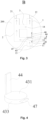
- the first sliding blocking member 4 further comprises a first protrusion 47, the first protrusion 47 is disposed at the first side surface 433 of the first blocking slider 43, and a height of the first protrusion is less than or equal to a height of the first side surface, where the first protrusion 47 is disposed at the side of the first sliding blocking member 4 facing the first distributing position 13, and the first abutting slider 44 is disposed at a side of the first sliding blocking member 4 away from the first distributing position 13.
- the first protrusion 47 is disposed at the first side surface 433 of the first blocking slider 43 and the height of the first protrusion 47 is less than or equal to the height of the first side surface 433, and disposed at the side of the first sliding blocking member 4 facing the first distributing position 13.
- the possibility of displacement of the first sliding blocking member 4 sliding to the first position 41 or the second position 42 is reduced; on the other hand, the first blocking slider 43 is supported, reducing the possibility of deformation due to the refrigerant impact.
- the shapes of the upper and lower surfaces of the first protrusion 47 are adapted to the shape of branch pipe 2 connecting the main pipe 1 of the first distributing position 13.
- the main pipe 1 comprises a first pipe section 15 between the first refrigerant pipe opening 11 and the first distributing position 13, where the first pipe section 15 is inclinedly disposed facing the first distributing position 13. As shown in Fig. 6 , the first pipe section 15 is inclined from the lower left toward the upper right.
- the first pipe section 15 is inclinedly disposed facing the first distributing position 13, thus, in the case where the refrigerant flows in from the first refrigerant pipe opening 11, the impact towards the upper right is formed on the first blocking slider 43 from the refrigerant, and the first blocking slider 43 and the first abutting slider 44 are tightly attached at the inner side wall of the main pipe 1 sliding from the first position 41 to the second position 42, ensuring the normal operating of first sliding blocking member 4.
- a one-way diverting device comprises: a main pipe 1, a branch pipe 2, a connecting branch pipe 3, and a second sliding blocking member 5.
- the main pipe 1 comprises a first refrigerant pipe opening 11 and a second refrigerant pipe openings 12 at two ends of the main pipe 1, respectively, and the main pipe 1 is provided with a first distributing position 13 closed to the first refrigerant pipe opening 11 and a second distributing position 14 closed to the second refrigerant pipe opening 12.
- One end of the branch pipe 2 is connected to the first distributing position 13 of the main pipe 1, and the other end of the branch pipe 2 is a third refrigerant pipe opening 21.
- the connecting branch pipe 3 connects the second distributing position 14 of the main pipe 1 to the branch pipe 2.
- the second sliding blocking member 5 is slidably disposed at the second distributing position 14. In a case where the second sliding blocking member 5 slides to the third position 51, the second refrigerant pipe opening 12 is blocked, and the refrigerant flows in from the first refrigerant pipe opening 11 and flows out from the third refrigerant pipe opening 21; in a case where the second sliding blocking member 5 slides to the fourth position 52, the second refrigerant pipe opening 12 is conducted, and the refrigerant flows in from the second refrigerant pipe opening 12 and the third refrigerant pipe opening 21, and flows out from the first refrigerant pipe opening 11.
- the one-way diverting device comprises a main pipe 1, a branch pipe 2, a connecting branch pipe 3, and a second sliding blocking member 5.
- the second sliding blocking member 5 slides to the third position 51, the second refrigerant pipe opening 12 is blocked, and the refrigerant flows in the first refrigerant pipe opening 11 and flows out from the third refrigerant pipe opening 21; in a case where the second sliding blocking element 5 slides to the fourth position 52, the second refrigerant pipe opening 12 is conducted, and the refrigerant flows in from the second refrigerant pipe opening 12 and the third refrigerant pipe opening 21, and flows out from the first refrigerant pipe opening 11.
- the one-way diverting device doesn't need to be provided with redundant valves, the flow direction of the refrigerant inside the one-way diverting device can be changed by blocking or conducting the first refrigerant pipe opening 12 by the second sliding blocking member 5, reducing the material cost and the space cost.
- the branch pipe 2 is connected to the first distributing position 13 of the main pipe 1
- the connecting branch pipe 3 connects the second distributing position 14 of the main pipe 1 to the branch pipe 2, thus the inside of the one-way diverting device is connected as a shape of two concentric squares.
- the inside of the one-way diverting device is not limited to the shape of two concentric squares, and it can be designed according to the actual requirement.
- the operation principle of the one-way diverting device is as follows: As shown in Figs 1 and 2 , the straight lines with arrows show the flow direction of the refrigerant.
- the refrigerant firstly flows in the second refrigerant pipe opening 12 and the third refrigerant pipe opening 21. Due to the refrigerant inside the air conditioner pipe having a certain flow velocity, the refrigerant flows in the third refrigerant pipe opening 12, and the flowing refrigerant pushes the second sliding blocking member 5 slides from the third position 51 to the fourth position 52.
- the second sliding blocking member 5 slides to the fourth position 52, the second refrigerant pipe opening 12 and the connecting branch pipe 3 are conducted, and due the branch pipe 2 connects to the first distributing position 13 of the main pipe 1, the refrigerant flows in from the second refrigerant pipe opening 12 and the third refrigerant pipe opening 21, and flows out from the first distributing position 11.
- the refrigerant in a case where the air conditioner is in the cooling operation and the refrigerant inside the air conditioner pipe flows along the one-way diverting device, the refrigerant firstly flows in the first refrigerant pipe opening 11. Due to the refrigerant inside the air conditioner pipe having a certain flow velocity, the refrigerant flows in the first refrigerant pipe opening 11, and the flowing refrigerant pushes the second sliding blocking member 5 slides from the fourth position 52 to the third position 51.
- the second sliding blocking member 5 comprises: a second blocking slider 53, a second abutting slider 54, a third locating member 55, and a fourth locating member 56.
- the second blocking slider 53 is disposed along a cross-section of the second distributing position 14 of the main pipe 1, and the second blocking slider 53 is slidable between the third position 51 of the second distributing position 14 and the fourth position 52 of the second distributing position 14.
- the second blocking slider 54 is fixedly connected to the second blocking slider 53 and abuts against the inner side wall of the main pipe 1, and the second abutting slider 54 is slidable along with the second blocking slider 53.
- the third locating member 55 is disposed at the inner side wall of the main pipe 1.
- the second blocking slider In a case where the second sliding blocking member 5 slides to the third position 51, the second blocking slider abuts against the third locating member 55.
- the fourth locating member 56 is disposed at the inner side wall of the main pipe 1. In a case where the second sliding blocking member 5 slides to the fourth position 52, the second abutting slider 54 buts against the fourth locating member 56.
- the third locating member 55 and the fourth locating member 56 are disposed at the inner side wall of the main pipe 1.
- the second blocking slider 53 abuts against the third locating member 55.
- the second abutting slider 54 abuts against the fourth locating member 56.
- the second blocking slider 53 and the second abutting slider 54 are limited by the third locating member 55 and the fourth locating member 56 respectively while sliding between the third position 51 and the fourth position 52, so as to realize the conduction and blocking between the second refrigerant pipe opening 12 and the connecting branch pipe 3, with simple in structure, reasonable in design and convenient in processing and manufacturing.
- an inside of the second blocking slider 53 is hollow or partly hollow.
- the inside of the second blocking slider 53 is hollow or partly hollow, reducing the weight of the second blocking slider 53, and reducing the resistance of slide of the second blocking slider 53 pushed by refrigerant between the third position 51 and the fourth position 52.
- the material of the second blocking slider 53 can be a composite of one or more nylon, plastics, or metallic materials.
- the material can be aluminum, copper, steel, and so on.
- the second blocking slider 53 can be made of solid material to reduce the possibility of deformation.
- the second blocking slider 53 comprises: a third bottom surface, a fourth bottom surface, and a second surface.
- the third bottom surface faces the inside of the main pipe 1.
- the fourth bottom surface faces the second refrigerant pipe opening 12.
- the second side surface is disposed surrounding between the third bottom surface and the fourth bottom surface.
- a perimeter of the third bottom surface has a third length
- an extended length of the second abutting slider 54 in the third bottom surface has a fourth length, where the fourth length is longer than or equal to 1/3 of the second length, and shorter than or equal to 1/2 of the third length.
- the fourth length is longer than or equal to 1/3 of the third length and shorter than or equal to 1/2 of the third length, thus the contact area between the second abutting slider 54 and the inner side wall of the main pipe 1 in a suitable range, improving the stability of the second sliding blocking member 5.
- the extended length of the second abutting slider 54 in the third bottom surface can be understood as the perimeter of a projection section of the second abutting slider 54 on the third bottom surface.
- the distance between the second side surface of the second blocking slider 53 and the inner side wall of the main pipe 1 at the second distributing position 14 is larger than or equal to 0.005mm, and smaller than or equal to 1mm.
- the distance between the second side surface of the second blocking slider 53 and the inner side wall of the main pipe 1 at the second distributing position 14 is larger than or equal to 0.005mm, and smaller than or equal to 1mm, thus satisfying the small matching distance between the third blocking slider 53 and the inner side wall of the main pipe 1 at the second distributing position 14, and not affects the sliding of the second blocking slider 53.
- the distance between the second side surface of the second blocking slider 53 and the inner side wall of the main pipe 1 at the second distributing position 14 is larger than or equal to 0.01 mm, and smaller than or equal to 0.02mm.
- the cross-section of the second distributing position 14 of the main pipe 1 is a polygon, and the second blocking slider 53 is shaped as same as the cross-section of the second distributing position 14.
- the second blocking slider 53 is shaped as same as the shape of the cross-section of the second distributing position 14 of the main pipe 1 and are both polygons, thus the second blocking slider 53 can be locked inside the main pipe 1, and in a case where the second blocking slider 53 slides back and forth at the second distributing position 14 of the main pipe 1, the second blocking slider 53 is hard to rotate, improving the stability of sliding of the second blocking slider 53.
- the second blocking slider 53 and the cross-section of the second distributing position 14 of the main pipe 1 can also both be a circle.
- the second blocking slider 53 and the cross-section of the second distributing position 14 of the main pipe 1 can be designed to other shapes according to the actual requirement.
- the third bottom surface of the second blocking slider 53 comprises a third edge and a fourth edge bending connected
- a second abutting slider 54 comprises a third abutting plate and a fourth abutting plate bending connected, where the third abutting plate is fixedly connected to the third edge, and the fourth abutting plate is fixedly connected to the fourth edge.
- the third bottom surface of the second blocking slider 53 comprises the third edge and the fourth edge bending connected
- the second abutting slider 54 comprises the third abutting plate and the fourth abutting plate bending connected
- the third abutting plate is fixedly connected to the third edge
- the fourth abutting plate is fixedly connected to the fourth edge; thus a contact angle is formed between the second abutting slider 54 and the inner side wall of the main pipe 1 at the second distributing position 14.
- the contact area of the second abutting slider 54 with the inner side wall surface can be increased, and the structural stability of the second abutting slider 54 can be improved; on the other hand, the rotating while sliding of the second blocking slider 53 can be prevented.
- the second sliding blocking member 5 further comprises a second protrusion 57, the second protrusion 57 is disposed at the second side surface of the first blocking slider 53, and a height of the second protrusion is less than or equal to a height of the second side surface, where the second protrusion 57 is disposed at the side of the second sliding blocking member 5 facing the second distributing position 14, and the second abutting slider 54 is disposed at the second sliding blocking member 5 away from the second distributing position 14.
- the second protrusion 57 is disposed at the second side surface of the second blocking slider 53 and the height of the second protrusion is less than or equal to the height of the second side surface, and disposed at the side surface of the second sliding blocking member 5 facing the second distributing position 14.
- the possibility of displacement of the second sliding blocking member 5 sliding to the third position 51 or the fourth position 52 is reduced.
- the second blocking slider 53 is supported, reducing the possibility of deformation due to the refrigerant impact.
- the shapes of the upper and lower surfaces of the second protrusion 57 are adapted to the inner side wall of the connecting branch pipe 3 connecting the main pipe 1 at the second distributing position 14.
- a main pipe 1 comprises a second pipe section 16 between the second refrigerant pipe opening 12 and the second distributing position 14, where the second pipe section 16 is inclinedly disposed facing the second distributing position 14.
- the second pipe section 16 is inclinedly disposed facing the second distributing position 14, thus, in the case where the refrigerant flows in from the second refrigerant pipe opening 12, the impact towards the upper left is formed on the second blocking slider 53 from the refrigerant, the second blocking slider 53 and the second abutting slider 54 are tightly attached the inner side wall of the main pipe 1 sliding from the third position 51 to the fourth position 52, ensuring the normal operating of second sliding blocking member 5.
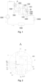
- variable diverting heat exchanger comprises a heat exchange pipe 100, a first one-way diverting device 200, a first distributor 300, a second one-way diverting device 400, a first bypass pipe 500, a second distributor 600, and a second bypass pipe 700.
- the heat exchange pipe 100 comprises a first heat exchange branch 101, a second heat exchange branch 102, and a third heat exchange branch 103 in parallel connection.
- the first one-way diverting device 200 is disposed at a first side of the heat exchange pipe 100, and the second refrigerant pipe opening 12 of the first one-way diverting device 200 is connected to the first heat exchange branch 101.
- the first distributor 300 is disposed at a second side of the heat exchange pipe 100, and the first distributor 300 is connected to the second heat exchange branch 102 and the third heat exchange branch 103.
- the second one-way diverting device 400 is disposed at the second side of the heat exchange pipe 100, and the third refrigerant pipe opening 21 of the second one-way diverting device 400 is connected to the first heat exchange branch 101.
- the first bypass pipe 500 connects the second refrigerant pipe opening 12 of the second one-way diverting device 400 with the first distributor 300.
- the second distributor 600 is disposed at the first side of the heat exchange pipe 100, and the second distributor 600 is connected to the third heat exchange branch 103.
- the second bypass pipe 700 connects the first refrigerant pipe opening 11 of the first one-way diverting device with the second distributor 600.
- the first one-way diverting device 200 is a one-way diverting device in the first aspect of the embodiments.
- the second one-way diverting device 400 is a one-way diverting device in the second aspect of the embodiments.
- variable diverting heat exchanger is provided according to the embodiment of the present disclosure and comprises the first one-way diverting device according to the first aspects of any one of the embodiments and the one-way diverting device according to the second aspect of any one of the embodiments, therefore the variable diverting heat exchanger has the beneficial effects of the one-way diverting device according to the first aspect of any one of the embodiments and the one-way diverting device according to the second aspect of any one of the embodiments, and not repeatedly described herein.
- an air conditioner comprises a compressor 800, an indoor heat exchanger 900, a throttle device 1000, a variable diverting heat exchanger, and a refrigerant circulation circuit thereof.
- the flow direction of the refrigerant is shown by the straight lines with arrows in Fig. 1 .
- the refrigerant in high-temperature and high-pressure from the compressor 800 flows in the indoor heat exchanger 900, the indoor heat exchanger 900 heats the indoor environment under the action of the fan.
- the cooled refrigerant flows into the throttle device 1000, and after the throttling and depressurization process of the throttle device 1000, the refrigerant flows into the variable diverting heat exchanger.
- the refrigerant firstly flows in the second distributor 600 of the variable diverting heat exchanger, then a part of the refrigerant flows in the third heat exchange branch 103 from the second distributor 600, the other part of the refrigerant flows in the first refrigerant pipe opening 11 of the first one-way diverting device 200 through the second bypass pipe 700, and then the refrigerant from the second refrigerant pipe opening 12 and the third refrigerant pipe opening 21 of the first one-way diverting device 200 flow in the first heat exchange branch 101 and the second heat exchange branch 102 respectively.
- the refrigerant from the second heat exchange branch 102 and the third heat exchange branch 103 flows in the first distributor 300.
- the refrigerant flowing in the first distributor 300 through the first bypass pipe 500 flows in the second refrigerant pipe opening 12 of the second one-way diverting device 400, the refrigerant flowing out from the first heat exchange branch 101 flows in from the third refrigerant pipe opening 21 of the second one-way diverting device 400, thus all of the refrigerant flows out the first refrigerant pipe opening 11 of the second one-way diverting device 400 and flows back to the compressor 800 for the next circulation.
- the first heat exchange branch 101, the second heat exchange branch 102, and the third heat exchange branch 103 are connected in parallel. This is, the refrigerant finishes heat exchange in a variable diverting heat exchanger body through three branches, ensuring the heat transfer coefficient and greatly reducing the pressure drop, thus improving the low-temperature heating production.
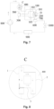
- the flow direction of the refrigerant is shown by the straight lines with arrows in Fig. 7 .
- the refrigerant in high-temperature and high-pressure form the compressor 800 flows into the variable diverting heat exchanger.
- the refrigerant firstly flows in the first refrigerant pipe opening 11 of the second one-way diverting device 400 of the variable diverting heat exchanger and then flows out from the third refrigerant pipe opening 21 of the second one-way diverting device 400.
- the refrigerant flowing out from the first heat exchange branch 101 flows in the second refrigerant pipe opening 12 of the first one-way diverting device 200 and flows out from the third refrigerant pipe opening 21 of the first one-way diverting device 200.
- the flowing out refrigerant flows in the second heat exchange branch 102, the first distributor 300, and the third heat exchange branch 103 in turn, and then flows in the second distributor 600 from the third heat exchange branch 103.
- the refrigerant flows out from the second distributor 600, the refrigerant flows in the throttle device 1000 for throttling and depressurization and then flows in the indoor heat exchanger 900, the indoor heat exchanger 900 cools the indoor air.
- the refrigerant After absorbing the heat of the indoor environment, the refrigerant flows back to the compressor 800 for the next circulation.
- the first heat exchange branch 101, the second heat exchange branch 102, and the third heat exchange branch 103 connect the second one-way diverting device 400, the first one-way diverting device 200, the first distributor 300, and the second distributor 600 in series. This is, the refrigerant completes heat exchange in variable diverting heat exchanger body flows through one path, accelerating the circulation of the refrigerant and increasing the high-temperature cooling production.
Landscapes
- Engineering & Computer Science (AREA)
- General Engineering & Computer Science (AREA)
- Mechanical Engineering (AREA)
- Physics & Mathematics (AREA)
- Thermal Sciences (AREA)
- Multiple-Way Valves (AREA)
Abstract
Description
- This application claims priority to Chinese Patent Application No.
CN20221 0547991 .X, filed on May 20, 2022 - The present disclosure relates to the technical field of air conditioners, and more particularly to a one-way diverting device and a variable diverting heat exchanger.
- The optimal flow paths are different when the air conditioner is in the cooling operation and the heating operation.
- In a case where an air conditioner is in the heating operation, a refrigerant of the heat exchange pipe of the outdoor heat exchanger is in a low-temperature and low-pressure condition, and the heat transfer performance is mainly affected by the heat transfer coefficient and the pressure drop together, which is suitable for a relatively large number of branches, and ensuring the heat transfer coefficient, the system pressure is increased by greatly reducing the pressure drop, thus improving the low-temperature heat production of the air conditioner. In a case where an air conditioner is in the cooling operation, a refrigerant of the heat exchange pipe of the outdoor heat exchanger is in a high-temperature and high-pressure condition, and the heat transfer performance is mainly affected by the heat transfer coefficient and is insensitive to the pressure drop, which is suitable for fewer branches to accelerate circulation and increase the heat transfer coefficient, thus improving the high-temperature cool production of the air conditioner. The conventional outdoor heat exchangers of the air conditioner mainly adopt variable diverting heat exchangers to control the transition of the above refrigerant flow paths between the heating operation and the cooling operation.
- During the implementation of the embodiment of the present disclosure, at least the following problems have been found in the related arts:
- The above variable diverting heat exchangers usually adopt one-way valves, solenoid valves, and other valves to realize the transition control of the refrigerant flow paths between the heating operation and the cooling operation. The increase of one-way valves, solenoid valves, and other valves often leads to the increase of solder points of the variable diverting heat exchanger. To ensure the safety distance of the solder, it is necessary to keep the solder safety distance more than 30mm between the solder points, thus the material cost and the space cost of the variable diverting heat exchanger are increased.
- In order to have a basic understanding of some aspects of the disclosed embodiments, a brief summary is given below. The summary is not intended to be a general comment to identify crucial/essential constituent elements or to describe the protection scope of these embodiments but rather to serve as a preface to the detailed description that follows.
- A one-way diverting device and a variable diverting heat exchanger are provided according to the embodiment of the present disclosure to solve the problem of the increase of material cost and space cost in a variable diverting heat exchanger due to the increase of solder points.
- According to a first aspect of the embodiments of the present disclosure, a one-way diverting device is provided and comprises: a main pipe, comprising a first refrigerant pipe opening and a second refrigerant pipe opening disposed at two ends of the main pipe, respectively, where the main pipe is provided with a first distributing position closed to the first refrigerant pipe opening and a second distributing position closed to the second refrigerant pipe opening; a branch pipe, where one end of the branch pipe is connected to the first distributing position of the main pipe, and the other end of the branch pipe is a third refrigerant pipe opening; a connecting branch pipe, connecting the second distributing position of the main pipe to the branch pipe; and a first sliding blocking member, slidably disposed the first distributing position; where in a case where the first sliding blocking member slides to a first position, the first refrigerant pipe opening is blocked, and the refrigerant flows in from the second refrigerant pipe opening and flows out from the third refrigerant pipe opening; and in a case where the first sliding blocking member slides to a second position, the first refrigerant pipe opening is conducted, and the refrigerant flows in from the first refrigerant pipe opening, and flows out from the second refrigerant pipe opening and the third refrigerant pipe opening.
- In some embodiments, the first sliding blocking member comprises: a first blocking slider, disposed along a cross-section of the first distributing position of the main pipe, and slidable between the first position of the first distributing position and the second position of the first distributing position; a first abutting slider, fixedly connected to the first blocking slider and abuts against an inner side wall of the main pipe; where the first abutting slider is slidable along with the first blocking slider, a first locating member, disposed at the inner side wall of the main pipe, in a case where the first sliding blocking member slides to the first position, the first blocking slider abuts against the first locating member; and a second locating member, disposed at the inner side wall of the main pipe; and in a case where the first sliding blocking member slides to the second position, the first abutting slider buts against the second locating member.
- In some embodiments, an inside of the first blocking slider is hollow or partly hollow.
- In some embodiments, the first blocking slider comprises: a first bottom surface, facing the inside of the main pipe; a second bottom surface, facing the first refrigerant pipe opening; and a first side surface, disposed surrounding between the first bottom surface and the second bottom surface, where the first abutting slider is disposed along a periphery of the first bottom surface, a perimeter of the first bottom surface has a first length, and an extended length of the first abutting slider in the first bottom surface has a second length, where the second length is longer than or equal to 1/3 of the first length and shorter than or equal to 1/2 of the first length.
- In some embodiments, a distance between the first side surface of the first blocking slider and the inner side wall of the main pipe at the first distributing position is larger than or equal to 0.005mm, and smaller than or equal to 1 mm.
- In some embodiments, the cross-section of the first distributing position of the main pipe is a polygon, and the first blocking slider is shaped as same as the cross-section of the first distributing position.
- In some embodiments, the first bottom surface of the first blocking slider comprises a first edge and a second edge bending connected; where the first abutting slider comprises a first abutting plate and a second abutting plate bending connected, the first abutting plate is fixedly connected to the first abutting plate and the second abutting plate is fixedly connected to the second edge.
- In some embodiments, the first sliding blocking member further comprises a first protrusion, the first protrusion is disposed at the first side surface of the first blocking slider, and a height of the first protrusion is less than or equal to a height of the first side surface; where the first protrusion is disposed at a side of the first sliding blocking member facing the first distributing position, and the first abutting slider is disposed at a side of the first sliding blocking member away from the first distributing position.
- In some embodiments, the main pipe comprises a first pipe section between the first refrigerant pipe opening and the first distributing position, where the first pipe section is inclinedly disposed facing the side of the first distributing position.
- According to a second aspect of the embodiments of the present disclosure, a one-way diverting device is provided and comprises: a main pipe, comprising a first refrigerant pipe opening and a second refrigerant pipe opening at two ends of the main pipe, respectively, and the main pipe is provided with a first distributing position closed to the first refrigerant pipe opening and a second distributing position closed to the second refrigerant pipe opening; a branch pipe, one end of the branch pipe is connected to the first distributing position of the main pipe, and the other end of the branch pipe is the third refrigerant pipe opening; a connecting branch pipe, connecting the second distributing position of the main pipe to the branch pipe; and a second sliding blocking member, slidably disposed at the second distributing position, in a case where the second sliding blocking member slides to a third position, the second refrigerant pipe opening is blocked, and the refrigerant flows in from the first refrigerant pipe opening and flows out from the third refrigerant pipe opening; in a case where the second sliding blocking member slides to a fourth position, the second refrigerant pipe opening is conducted, and the refrigerant flows in from the second refrigerant pipe opening and the third refrigerant pipe opening, and flows out from the first refrigerant pipe opening.
- In some embodiments, the second sliding blocking member comprises: a second blocking slider, disposed along a cross-section of the second distributing position of the main pipe, and is slidable between the third position of the second distributing position and the fourth position of the second distributing position, a second abutting slider, fixedly connected to the second blocking slider and abuts against the inner side wall of the main pipe, and the second abutting slider is slidable along with the second blocking slider; a third locating member, disposed at an inner side wall of the main pipe, in a case where the second sliding blocking member slides to the third position, the second blocking slider abuts against the third locating member; and a fourth locating member, disposed at the inner side wall of the main pipe; in a case where the second sliding blocking member slides to the fourth position, the second abutting slider buts against the fourth locating member.
- In some embodiments, an inside of the second blocking slider is hollow or partly hollow.
- In some embodiments, the second blocking slider comprises: a third bottom surface, facing the inside of the main pipe; a fourth bottom surface, facing the second refrigerant pipe opening; and a second side surface, disposed surrounded between the third side surface and the fourth bottom surface, where the second abutting slider is disposed along a periphery of the third bottom surface, a perimeter of the third bottom surface has a third length, and an extended length of the second abutting slider in the third bottom surface ha a fourth length, where the fourth length is longer than or equal to 1/3 of the third length, and shorter than or equal to 1/2 of the third length.
- In some embodiments, the distance between the second side surface of the second blocking slider and the inner side wall of the main pipe at the second distributing position is larger than or equal to 0.005mm, and smaller than or equal to 1mm.
- In some embodiments, a cross-section of the second distributing position of the main pipe is a polygon, and the second blocking slider is shaped as same as the cross-section at the second distributing position.
- In some embodiments, the third bottom surface of the second blocking slider comprises a third edge and a fourth edge bending connected, where a second abutting slider comprises a third abutting plate and a fourth abutting plate bending connected, the third abutting plate is fixedly connected to the third abutting plate, and the fourth abutting plate is fixedly connected to the fourth edge.
- In some embodiments, the second sliding blocking member further comprises a second protrusion, disposed at the second side surface of the second blocking slider, and a height of the second protrusion is less than or equal to a height of the second side surface, where the second protrusion is disposed at a side of the second sliding blocking member facing the second distributing position, and the second abutting slider is disposed at a side of the second sliding blocking member away from the second distributing position.
- In some embodiments, a main pipe comprises a second pipe section between the second refrigerant pipe opening and the second distributing position, where the second pipe section is inclinedly disposed facing the second distributing position.
- According to a third aspect of the embodiments of the embodiment, a variable diverting heat exchanger is provided and comprises: a heat exchange pipe, comprising a first heat exchange branch, a second heat exchange branch, and a third heat exchange branch connected in parallel; a first one-way diverting device, disposed at the first side of the heat exchange pipe, where a second refrigerant pipe opening of the first one-way diverting device is connected to the first heat exchange branch; a first distributor, disposed at the second side of the heat exchange pipe, where the first distributor is connected to the second heat exchange branch and the third heat exchange branch; a second one-way diverting device, disposed at the second side of the heat exchange pipe, where a third refrigerant pipe opening of the second one-way diverting device is connected to the first heat exchange branch; a first bypass pipe, connecting the second refrigerant pipe opening of the second one-way diverting device with the first distributor; a second distributor, disposed at the first side of the heat exchange pipe, where the second distributor is connected to the third heat exchange pipe; and a second bypass pipe, connecting a first refrigerant pipe opening of the first one-way diverting device and the second distributor, where the first one-way diverting device is a one-way diverting device according to any one of the first aspects of the embodiments, and the second one-way diverting device is a one-way diverting device according to any one of the second aspect of the embodiments.
- The one-way diverting device and the variable diverting heat exchanger provided by the embodiment of the present disclosure can have the following technical advantages:
- The variable diverting heat exchanger provided by the embodiment of the present disclosure comprises a heat exchange pipe, a first distributor, a second distributor, a first bypass pipe, a second bypass pipe, a first one-way diverting device, and a second one-way diverting device. The first one-way diverting device and a second one-way diverting device both comprise a main pipe, a branch pipe, and a connecting branch pipe, where a first refrigerant pipe opening and a second refrigerant pipe opening are disposed at the two ends of the main pipe respectively, a first distributing position is disposed at the main pipe closed to the first refrigerant pipe opening, and a second distributing position is disposed at the main pipe closed to the second refrigerant pipe opening. One end of the branch pipe is connected to the first distributing position; the other end of the branch pipe is the third refrigerant pipe opening. The connecting branch pipe connects the second distributing position and the branch pipe.
- The first one-way diverting device further comprises a first sliding blocking member, the first sliding blocking member is disposed at the first distributing position. In a case where the first sliding blocking member slides to the first position, the first refrigerant pipe opening is blocked, and the refrigerant flows in from the second refrigerant pipe opening, and flows out from the third refrigerant pipe opening. In a case where the first sliding blocking member slides to the second position, the first refrigerant pipe opening is conducted, and the refrigerant flows in from the first refrigerant pipe opening and flows out from the second refrigerant pipe opening and the third refrigerant pipe opening. The first one-way diverting device doesn't need to be provided with redundant valves, the flow direction of the refrigerant inside the first one-way diverting device can be changed by blocking or conducting the first refrigerant pipe opening by the first sliding blocking member, reducing the material cost and the space cost.
- The second one-way diverting device further comprises a second sliding blocking member, the second sliding blocking member is disposed at the second distributing position. In a case where the second sliding blocking member slides to the third position, the second refrigerant pipe opening is blocked, and the refrigerant flows in from the first refrigerant pipe opening, and flows out from the third refrigerant pipe opening. In a case where the second sliding blocking member slides to the fourth position, the second refrigerant pipe opening is conducted, and the refrigerant flows in from the second refrigerant pipe opening and the third refrigerant pipe opening, and flows out from the first refrigerant pipe opening. The second one-way diverting device doesn't need to be provided with redundant valves, the flow direction of the refrigerant inside the second one-way diverting device can be changed by blocking or conducting the second refrigerant pipe opening by the second sliding blocking member, reducing the material cost and the space cost.
- The above general description and the description below are exemplary and explanatory only and are not intended to limit the present disclosure.
- One or more embodiments are illustrated by means of the corresponding drawings, which do not constitute a limitation of the embodiments, elements having the same reference numerals in the drawings are shown as similar elements, and the drawings do not constitute a limitation of proportion, where:
-
Fig. 1 is a schematic structure diagram of a variable diverting heat exchanger in the heating operation according to an embodiment of the present disclosure; -
Fig. 2 is an enlarged schematic structure diagram of area A ofFig. 1 ; -
Fig. 3 is an enlarged schematic structure diagram of area B ofFig. 1 ; -
Fig. 4 is a partial schematic structure diagram of a first sliding blocking member according to the embodiment of the present disclosure; -
Fig. 5 is a partial schematic structure diagram of another first sliding blocking member according to the embodiment of the present disclosure; -
Fig. 6 is a schematic structure diagram of another variable diverting heat exchanger in the heating operation according to the embodiment of the present disclosure; -
Fig. 7 is a schematic structure diagram of a variable diverting heat exchanger in the cooling operation according to the embodiment of the present disclosure; -
Fig. 8 is an enlarged schematic structure diagram of area C ofFig. 7 ; -
Fig. 9 is an enlarged schematic structure diagram of area D ofFig. 7 . -
- 1: main pipe; 2: branch pipe; 3: connecting branch pipe; 4: first sliding blocking member; 5: second sliding blocking member;
- 100: heat exchange pipe; 200: first one-way diverting device; 300: first distributor; 400: second one-way diverting device; 500: first bypass pipe; 600: second distributor; 700: second bypass pipe; 800: compressor; 900: indoor heat exchanger; 1000: throttle device;
- 101: first heat exchange branch; 102: second heat exchange branch; 103: third heat exchange branch;
- 11: first refrigerant pipe opening; 12:second refrigerant pipe opening; 13:first distributing position; 14:second distributing position; 15:first pipe section; 16: second pipe section; 21:third refrigerant pipe opening; 41: first position; 42: second position; 43: first blocking slider; 431: first bottom surface; 4311: first edge; 4312: second edge; 432:second bottom surface; 433: first side surface; 44: first abutting slider; 441: first abutting plate; 442: second abutting plate; 45: first locating member; 46: second locating member; 47: first protrusion; 51: third position; 52: fourth position; 53: second blocking slider; 54: second abutting slider; 55: third locating member; 56: fourth locating member; 57: second protrusion.
- In order to enable a more detailed understanding of the features and technical content of the embodiments of the present disclosure, the implementation of the embodiments of the present disclosure will be described in detail below in conjunction with the accompanying drawings, which are for illustration only and are not intended to limit the embodiments of the present disclosure. In the following technical description for convenience of explanation, several details are provided for a full understanding of the disclosed embodiments. However, one or more embodiments may still be practiced without these details. In other instances, the well-known structures and devices may simplify the disclosure in order to simplify the drawings.
- The terms "first", "second" and the like in the specification and claims of embodiments of the present disclosure and the above drawings are used to distinguish similar elements and are not necessarily used to describe a particular order or priority. It should be understood that the data used in this way can be interchanged where appropriate for the embodiments of the present disclosure described herein. Furthermore, the terms "include" and "have" and any variations thereof are intended to cover a non-exclusive inclusion.
- In embodiments of the present disclosure, directional or positional relationships indicated by terms such as "up", "down", "on", "in", "interior", "out", "front" and "rear" is based on the directional or positional relationship shown in the figures. These terms are mainly intended to describe embodiments of the present disclosure, not to limit that the described devices, elements or components must have a specific orientation or be configured and operated in a specific orientation. Furthermore, in addition to indicating the directional or positional relationship, the above partial terms might also be used to convey other meanings, for example, the term "on" might also be used to indicate a dependency relationship or connectional relationship in some cases. Those having ordinary skills in the art may understand specific meanings of these terms in the embodiments of the present disclosure according to specific situations.
- In addition, the terms "dispose", "connect" and "fix" should be understood in a broad sense. For example, "connect" may be a fixed connection, detachable connection or integral connection, may be mechanical connection or electrical connection, may be direct connection, or indirect connection through an intermediate medium, or may be internal communication between two devices, elements or components. Those having ordinary skills in the art may understand specific meanings of the above terms in the embodiments of the present disclosure according to specific situations.
- Unless otherwise illustrated, the term "a plurality of" means two or more.
- Embodiments of the present disclosure and features in the embodiments may be combined with one another without conflict.
- As shown in
Figs. 1 ,3 , and9 , according to a first aspect of the embodiment of the present disclosure, a one-way diverting device is provided and comprises: amain pipe 1, abranch pipe 2, a connectingbranch pipe 3, and a first sliding blockingmember 4. Themain pipe 1 comprises a firstrefrigerant pipe opening 11 and a second refrigerant pipe opening 12 at two ends of themain pipe 1, respectively, and themain pipe 1 is provided with a first distributingposition 13 closed to the firstrefrigerant pipe opening 11 and a second distributingposition 14 closed to the secondrefrigerant pipe opening 12. One end of thebranch pipe 2 is connected to the first distributingposition 13 of themain pipe 1, and the other end of thebranch pipe 2 is a thirdrefrigerant pipe opening 21. The connectingbranch pipe 3 connects the second distributingposition 14 of themain pipe 1 to thebranch pipe 2. The first sliding blockingmember 4 is slidably disposed at the first distributingposition 13. In a case where the first sliding blockingmember 4 slides to afirst position 41, the first refrigerant pipe opening 11 is blocked, and the refrigerant flows in from the secondrefrigerant pipe opening 12 and flows out from the thirdrefrigerant pipe opening 21; in a case where the first sliding blockingmember 4 slides to asecond position 42, the first refrigerant pipe opening 11 is conducted, and the refrigerant flows in from the firstrefrigerant pipe opening 11, and flows out from the secondrefrigerant pipe opening 12 and the thirdrefrigerant pipe opening 21. - Adopting the one-way diverting device according to the embodiment of the present disclosure, comprising a
main pipe 1, abranch pipe 2, a connectingbranch pipe 3, and a first sliding blockingmember 4. In a case where the first sliding blockingmember 4 slides to thefirst position 41, the first refrigerant pipe opening 11 is blocked, and the refrigerant flows in from the secondrefrigerant pipe opening 12 and flows out from the thirdrefrigerant pipe opening 21; and in a case where the first sliding blockingmember 4 slides to thesecond position 42, the first refrigerant pipe opening 11 is conducted, and the refrigerant flows in from the firstrefrigerant pipe opening 11, and flows out from the secondrefrigerant pipe opening 12 and the thirdrefrigerant pipe opening 21. The one-way diverting device doesn't need to be provided with redundant valves, the flow direction of the refrigerant inside the one-way diverting device can be changed by blocking or conducting the first refrigerant pipe opening 11 by the first sliding blockingmember 4, reducing the material cost and the space cost. - In the embodiment of the present disclosure, the
branch pipe 2 is connected to the first distributingposition 13 of themain pipe 1, the connectingbranch pipe 3 connects the second distributingposition 14 of themain pipe 1 to thebranch pipe 2, thus the inside of the one-way diverting device is connected as the shape of two concentric squares. It should be understood that, according to the above connection form of thebranch pipe 2, themain pipe 1, and the connectingbranch pipe 3, the inside of the one-way diverting device is not limited to the shape of two concentric squares, and it can be designed according to the actual requirement. - The operation principle of the one-way diverting device is as follows:
- As shown in
Figs 1 and3 , the straight lines with arrows show the flow direction of the refrigerant. In a case where the air conditioner is in the heating operation and the refrigerant inside the air conditioner pipe flows along the one-way diverting device, the refrigerant firstly flows in the firstrefrigerant pipe opening 11. Due to the refrigerant inside the air conditioner pipe having a certain flow velocity, the refrigerant flows in the firstrefrigerant pipe opening 11, and the flowing refrigerant pushes the first sliding blockingmember 4 slides from thefirst position 41 to thesecond position 42. In a case where the first sliding blockingmember 4 slides to thesecond position 42, the firstrefrigerant pipe opening 11 and thebranch pipe 2 are conducted. Since the connectingbranch pipe 3 connects the second distributingposition 14 of themain pipe 1 andbranch pipe 2, the refrigerant flows out from the second refrigerant pipe opening 12 of themain pipe 1 and the third refrigerant pipe opening 21 of the other end of thebranch pipe 2. - As shown in
Figs 7 and9 , in a case where the air conditioner is in the cooling operation and the refrigerant inside the air conditioner pipe flows along the one-way diverting device, the refrigerant firstly flows in the secondrefrigerant pipe opening 12. Due to the refrigerant inside the air conditioner pipe having a certain flow velocity, the refrigerant flows in the secondrefrigerant pipe opening 12, and the flowing refrigerant pushes the first sliding blockingmember 4 slides from thesecond position 42 to thefirst position 41. In a case where the first sliding blockingmember 4 slides to thefirst position 41, the first refrigerant pipe opening 11 is blocked. Since the first distributingposition 13 of themain pipe 1 andbranch pipe 2 are connected, and the second distributingposition 14 of themain pipe 1 and thebranch pipe 2 are connected by the connectingbranch pipe 3, the refrigerant flows out from the third refrigerant pipe opening 21 of thebranch pipe 2. - In some optional embodiments, as shown in
Fig. 3 , the first sliding blockingmember 4 comprises: afirst blocking slider 43, a first abuttingslider 44, a first locatingmember 45, and a second locatingmember 46. Thefirst blocking slider 43 is disposed along a cross-section of the first distributingposition 13 of themain pipe 1, and is slidable between thefirst position 41 of the first distributingposition 13 and thesecond position 42 of the first distributingposition 13. Thefirst blocking slider 44 is fixedly connected to thefirst blocking slider 43 and abuts against the inner side wall of themain pipe 1, and the first abuttingslider 44 is slidable along with thefirst blocking slider 43. The first locatingmember 45 is disposed at the inner side wall of themain pipe 1. In a case where the first sliding blockingmember 4 slides to thefirst position 41, thefirst blocking slider 43 abuts against the first locatingmember 45. The second locatingmember 46 is disposed at the inner side wall of themain pipe 1. In a case where the first sliding blockingmember 4 slides to thesecond position 42, the first abuttingslider 44 buts against the second locatingmember 46. - Adopting the optional embodiments, the first locating
member 45 and the second locatingmember 46 are disposed at the inner side wall of themain pipe 1. In a case where the first sliding blockingmember 4 slides to thefirst position 41, thefirst blocking slider 43 abuts against the first locatingmember 45; and in a case where the first sliding blockingmember 4 slides to thesecond position 42, thefirst blocking slider 44 abuts against the second locatingmember 46. This is, thefirst blocking slider 43 and the first abuttingslider 44 are limited by the first locatingmember 45 and the second locatingmember 46 respectively while sliding between thefirst position 41 and thesecond position 42, so as to realize the conduction and blocking between the firstrefrigerant pipe opening 11 and thebranch pipe 2, with simple in structure, reasonable in design and convenient in processing and manufacturing. - In some optional embodiments, an inside of the
first blocking slider 43 is hollow or partly hollow. - Adopting the optional embodiments, the inside of the
first blocking slider 43 is hollow or partly hollow, reducing the weight of thefirst blocking slider 43 and reducing the resistance of the slide of thefirst blocking slider 43 pushed by refrigerant between thefirst position 41 and thesecond position 42. - Optionally, the material of the
first blocking slider 43 can be a composite of one or more nylon, plastics, or metallic materials. In a case where the material of thefirst blocking slider 43 is metallic, the material can be aluminum, copper, steel, and so on. - It should be understood that, in a case where the weight of the
first blocking slider 43 does not affect the push of the refrigerant, thefirst blocking slider 43 can be made of solid material to reduce the possibility of deformation. - In some optional embodiments, as shown in
Figs 4 ,5 , and9 , thefirst blocking slider 43 comprises: a firstbottom surface 431, a secondbottom surface 432, and afirst side surface 433. The firstbottom surface 431 faces the inside of themain pipe 1. The secondbottom surface 432 faces the firstrefrigerant pipe opening 11. Thefirst side surface 433 is disposed surrounding between the firstbottom surface 431 and the secondbottom surface 432. The first abuttingslider 44 is disposed along a periphery of the firstbottom surface 431, a perimeter of the firstbottom surface 431 has a first length, and an extended length of the first abuttingslider 44 in the firstbottom surface 431 has the second length. The second length is longer than or equal to 1/3 of the first length and shorter than or equal to 1/2 of the first length. - Adopting the optional embodiments, by setting the relationship between the first length and the second length as: the second length is longer than or equal to 1/3 of the first length and shorter than or equal to 1/2 of the first length, thus the contact area between the first abutting
slider 44 and the inner side wall of themain pipe 1 in a suitable range, improving the stability of the first sliding blockingmember 4. - Optionally, in a case where the first abutting
slider 44 is vertical to the firstbottom surface 431, the extended length of the first abuttingslider 44 is in the firstbottom surface 431, this is the second length, can be understood as the perimeter of a projection section of the first abuttingslider 44 on the firstbottom surface 431. - In some optional embodiments, the distance between the
first side surface 433 of thefirst blocking slider 43 and the inner side wall of themain pipe 1 at the first distributingposition 13 is larger than or equal to 0.005mm, and smaller than or equal to 1 mm. - Adopting the optional embodiments, the distance between the
first side surface 433 of thefirst blocking slider 43 and the inner side wall of themain pipe 1 at the first distributingposition 13 is larger than or equal to 0.005mm, and smaller than or equal to 1 mm, thus satisfying the small matching distance between thefirst blocking slider 43 and the inner side wall of themain pipe 1 at the first distributingposition 13, improving the stability of the sliding of thefirst blocking slider 43 and not affecting the sliding of the first blocking slider. - Preferably, the distance between the
first side surface 433 of thefirst blocking slider 43 and the inner side wall of themain pipe 1 at the first distributingposition 13 is larger than or equal to 0.01mm, and smaller than or equal to 0.02mm. - In some optional embodiments, as shown in
Fig. 5 , the cross-section of the first distributingposition 13 of themain pipe 1 is a polygon, and thefirst blocking slider 43 is shaped as same as the cross-section of the first distributingposition 13. - Adopting the optional embodiments, the
first blocking slider 43 is shaped as same as the cross-section of the first distributingposition 13 and are both polygons, thus thefirst blocking slider 43 can be locked inside themain pipe 1, and in a case where thefirst blocking slider 43 slides back and forth at the first distributingposition 13 of themain pipe 1, the first blocking slider is hard to rotate and improving the stability of sliding of thefirst blocking slider 43. - It should be understood that, the
first blocking slider 43 and the cross-section of the first distributingposition 13 of themain pipe 1 can also both be a circle, as shown inFig. 4 . Of course, thefirst blocking slider 43 and the cross-section of the first distributingposition 13 of themain pipe 1 can be designed to other shapes according to the actual requirement. - In some optional embodiments, as shown in
Fig. 5 , the firstbottom surface 431 of thefirst blocking slider 43 comprises afirst edge 4311 and asecond edge 4312 bending connected, where the first abuttingslider 44 comprises a firstabutting plate 441 and a secondabutting plate 442 bending connected, the first abuttingplate 441 is fixedly connected to thefirst edge 4311, and the secondabutting plate 442 is fixedly connected to thesecond edge 4312. - Adopting the optional embodiments, the first
bottom surface 431 of thefirst blocking slider 43 comprises thefirst edge 4311 and thesecond edge 4312 bending connected, the first abuttingslider 44 comprises the first abuttingplate 441 and the secondabutting plate 442, the first abuttingplate 441 is fixedly connected to thefirst edge 4311, and the secondabutting plate 442 is fixedly connected to thesecond edge 4312. Thus, a contact angle is formed between the first abuttingslider 44 and the inner side wall of themain pipe 1 at the first distributingposition 13. On one hand, the contact area of the first abuttingslider 44 with the inner side wall surface can be increased, and the structural stability of the first abuttingslider 44 can be improved; on the other hand, the rotating while sliding of thefirst blocking slider 43 can be prevented. - In some optional embodiments, as shown in
Figs. 3, 4 , and5 , the first sliding blockingmember 4 further comprises afirst protrusion 47, thefirst protrusion 47 is disposed at thefirst side surface 433 of thefirst blocking slider 43, and a height of the first protrusion is less than or equal to a height of the first side surface, where thefirst protrusion 47 is disposed at the side of the first sliding blockingmember 4 facing the first distributingposition 13, and the first abuttingslider 44 is disposed at a side of the first sliding blockingmember 4 away from the first distributingposition 13. - Adopting the optional embodiments, the
first protrusion 47 is disposed at thefirst side surface 433 of thefirst blocking slider 43 and the height of thefirst protrusion 47 is less than or equal to the height of thefirst side surface 433, and disposed at the side of the first sliding blockingmember 4 facing the first distributingposition 13. On one hand, the possibility of displacement of the first sliding blockingmember 4 sliding to thefirst position 41 or thesecond position 42 is reduced; on the other hand, thefirst blocking slider 43 is supported, reducing the possibility of deformation due to the refrigerant impact. - It should be understood that, the shapes of the upper and lower surfaces of the
first protrusion 47 are adapted to the shape ofbranch pipe 2 connecting themain pipe 1 of the first distributingposition 13. - In some optional embodiments, the
main pipe 1 comprises afirst pipe section 15 between the firstrefrigerant pipe opening 11 and the first distributingposition 13, where thefirst pipe section 15 is inclinedly disposed facing the first distributingposition 13. As shown inFig. 6 , thefirst pipe section 15 is inclined from the lower left toward the upper right. - Adopting the optional embodiments, the
first pipe section 15 is inclinedly disposed facing the first distributingposition 13, thus, in the case where the refrigerant flows in from the firstrefrigerant pipe opening 11, the impact towards the upper right is formed on thefirst blocking slider 43 from the refrigerant, and thefirst blocking slider 43 and the first abuttingslider 44 are tightly attached at the inner side wall of themain pipe 1 sliding from thefirst position 41 to thesecond position 42, ensuring the normal operating of first sliding blockingmember 4. - As shown in
Figs. 1, 2 , and8 , according to a second aspect of the embodiments of the present disclosure, a one-way diverting device is provided and comprises: amain pipe 1, abranch pipe 2, a connectingbranch pipe 3, and a second sliding blockingmember 5. Themain pipe 1 comprises a firstrefrigerant pipe opening 11 and a secondrefrigerant pipe openings 12 at two ends of themain pipe 1, respectively, and themain pipe 1 is provided with a first distributingposition 13 closed to the firstrefrigerant pipe opening 11 and a second distributingposition 14 closed to the secondrefrigerant pipe opening 12. One end of thebranch pipe 2 is connected to the first distributingposition 13 of themain pipe 1, and the other end of thebranch pipe 2 is a thirdrefrigerant pipe opening 21. The connectingbranch pipe 3 connects the second distributingposition 14 of themain pipe 1 to thebranch pipe 2. The second sliding blockingmember 5 is slidably disposed at the second distributingposition 14. In a case where the second sliding blockingmember 5 slides to thethird position 51, the second refrigerant pipe opening 12 is blocked, and the refrigerant flows in from the firstrefrigerant pipe opening 11 and flows out from the thirdrefrigerant pipe opening 21; in a case where the second sliding blockingmember 5 slides to thefourth position 52, the second refrigerant pipe opening 12 is conducted, and the refrigerant flows in from the secondrefrigerant pipe opening 12 and the thirdrefrigerant pipe opening 21, and flows out from the firstrefrigerant pipe opening 11. - Adopting the one-way diverting device according to the embodiment of the present disclosure, the one-way diverting device comprises a
main pipe 1, abranch pipe 2, a connectingbranch pipe 3, and a second sliding blockingmember 5. In a case where the second sliding blockingmember 5 slides to thethird position 51, the second refrigerant pipe opening 12 is blocked, and the refrigerant flows in the firstrefrigerant pipe opening 11 and flows out from the thirdrefrigerant pipe opening 21; in a case where the second sliding blockingelement 5 slides to thefourth position 52, the second refrigerant pipe opening 12 is conducted, and the refrigerant flows in from the secondrefrigerant pipe opening 12 and the thirdrefrigerant pipe opening 21, and flows out from the firstrefrigerant pipe opening 11. The one-way diverting device doesn't need to be provided with redundant valves, the flow direction of the refrigerant inside the one-way diverting device can be changed by blocking or conducting the first refrigerant pipe opening 12 by the second sliding blockingmember 5, reducing the material cost and the space cost. - In the embodiment of the present disclosure, the
branch pipe 2 is connected to the first distributingposition 13 of themain pipe 1, the connectingbranch pipe 3 connects the second distributingposition 14 of themain pipe 1 to thebranch pipe 2, thus the inside of the one-way diverting device is connected as a shape of two concentric squares. It should be understood that, according to the above connection form of thebranch pipe 2, themain pipe 1, and the connectingbranch pipe 3, the inside of the one-way diverting device is not limited to the shape of two concentric squares, and it can be designed according to the actual requirement. - The operation principle of the one-way diverting device is as follows:
As shown inFigs 1 and 2 , the straight lines with arrows show the flow direction of the refrigerant. In a case where the air conditioner is in the heating operation and the refrigerant inside the air conditioner pipe flows along the one-way diverting device, the refrigerant firstly flows in the secondrefrigerant pipe opening 12 and the thirdrefrigerant pipe opening 21. Due to the refrigerant inside the air conditioner pipe having a certain flow velocity, the refrigerant flows in the thirdrefrigerant pipe opening 12, and the flowing refrigerant pushes the second sliding blockingmember 5 slides from thethird position 51 to thefourth position 52. In a case where the second sliding blockingmember 5 slides to thefourth position 52, the secondrefrigerant pipe opening 12 and the connectingbranch pipe 3 are conducted, and due thebranch pipe 2 connects to the first distributingposition 13 of themain pipe 1, the refrigerant flows in from the secondrefrigerant pipe opening 12 and the thirdrefrigerant pipe opening 21, and flows out from the first distributingposition 11. - As shown in
Figs 7 and 8 , in a case where the air conditioner is in the cooling operation and the refrigerant inside the air conditioner pipe flows along the one-way diverting device, the refrigerant firstly flows in the firstrefrigerant pipe opening 11. Due to the refrigerant inside the air conditioner pipe having a certain flow velocity, the refrigerant flows in the firstrefrigerant pipe opening 11, and the flowing refrigerant pushes the second sliding blockingmember 5 slides from thefourth position 52 to thethird position 51. In a case where the second sliding blockingmember 5 slides to thethird position 51, the second refrigerant pipe opening 12 is blocked, and the connectingbranch pipe 3 connects the second distributingposition 14 of themain pipe 1 to thebranch pipe 2, thus the refrigerant flows out from the third refrigerant pipe opening 21 of thebranch pipe 2. - In some optional embodiments, as shown in
Fig. 2 , the second sliding blockingmember 5 comprises: asecond blocking slider 53, a second abuttingslider 54, a third locatingmember 55, and a fourth locatingmember 56. Thesecond blocking slider 53 is disposed along a cross-section of the second distributingposition 14 of themain pipe 1, and thesecond blocking slider 53 is slidable between thethird position 51 of the second distributingposition 14 and thefourth position 52 of the second distributingposition 14. Thesecond blocking slider 54 is fixedly connected to thesecond blocking slider 53 and abuts against the inner side wall of themain pipe 1, and the second abuttingslider 54 is slidable along with thesecond blocking slider 53. The third locatingmember 55 is disposed at the inner side wall of themain pipe 1. In a case where the second sliding blockingmember 5 slides to thethird position 51, the second blocking slider abuts against the third locatingmember 55. The fourth locatingmember 56 is disposed at the inner side wall of themain pipe 1. In a case where the second sliding blockingmember 5 slides to thefourth position 52, the second abuttingslider 54 buts against the fourth locatingmember 56. - Adopting the optional embodiments, the third locating
member 55 and the fourth locatingmember 56 are disposed at the inner side wall of themain pipe 1. In a case where the second sliding blockingmember 5 slides to thethird position 51, thesecond blocking slider 53 abuts against the third locatingmember 55. In a case where the second sliding blockingmember 5 slides to thefourth position 52, the second abuttingslider 54 abuts against the fourth locatingmember 56. This is, thesecond blocking slider 53 and the second abuttingslider 54 are limited by the third locatingmember 55 and the fourth locatingmember 56 respectively while sliding between thethird position 51 and thefourth position 52, so as to realize the conduction and blocking between the secondrefrigerant pipe opening 12 and the connectingbranch pipe 3, with simple in structure, reasonable in design and convenient in processing and manufacturing. - In some optional embodiments, an inside of the
second blocking slider 53 is hollow or partly hollow. - Adopting the optional embodiments, the inside of the
second blocking slider 53 is hollow or partly hollow, reducing the weight of thesecond blocking slider 53, and reducing the resistance of slide of thesecond blocking slider 53 pushed by refrigerant between thethird position 51 and thefourth position 52. - Optionally, the material of the
second blocking slider 53 can be a composite of one or more nylon, plastics, or metallic materials. In a case where the material of thesecond blocking slider 53 is metallic, the material can be aluminum, copper, steel, and so on. - It should be understood that, in a case where the weight of the
second blocking slider 53 does not affect the push of the refrigerant, thesecond blocking slider 53 can be made of solid material to reduce the possibility of deformation. - In some optional embodiments, the
second blocking slider 53 comprises: a third bottom surface, a fourth bottom surface, and a second surface. The third bottom surface faces the inside of themain pipe 1. The fourth bottom surface faces the secondrefrigerant pipe opening 12. The second side surface is disposed surrounding between the third bottom surface and the fourth bottom surface. Where the second abuttingslider 54 is disposed along a periphery of the third bottom surface, a perimeter of the third bottom surface has a third length, and an extended length of the second abuttingslider 54 in the third bottom surface has a fourth length, where the fourth length is longer than or equal to 1/3 of the second length, and shorter than or equal to 1/2 of the third length. - Adopting the optional embodiments, by setting the relationship between the third length and the fourth length as: the fourth length is longer than or equal to 1/3 of the third length and shorter than or equal to 1/2 of the third length, thus the contact area between the second abutting
slider 54 and the inner side wall of themain pipe 1 in a suitable range, improving the stability of the second sliding blockingmember 5. - Optionally, in a case where the second abutting
slider 54 is vertical to the third bottom surface, the extended length of the second abuttingslider 54 in the third bottom surface, this is the fourth length, can be understood as the perimeter of a projection section of the second abuttingslider 54 on the third bottom surface. - In some optional embodiments, the distance between the second side surface of the
second blocking slider 53 and the inner side wall of themain pipe 1 at the second distributingposition 14 is larger than or equal to 0.005mm, and smaller than or equal to 1mm. - Adopting the optional embodiments, the distance between the second side surface of the
second blocking slider 53 and the inner side wall of themain pipe 1 at the second distributingposition 14 is larger than or equal to 0.005mm, and smaller than or equal to 1mm, thus satisfying the small matching distance between thethird blocking slider 53 and the inner side wall of themain pipe 1 at the second distributingposition 14, and not affects the sliding of thesecond blocking slider 53. - Preferably, the distance between the second side surface of the
second blocking slider 53 and the inner side wall of themain pipe 1 at the second distributingposition 14 is larger than or equal to 0.01 mm, and smaller than or equal to 0.02mm. - In some optional embodiments, the cross-section of the second distributing
position 14 of themain pipe 1 is a polygon, and thesecond blocking slider 53 is shaped as same as the cross-section of the second distributingposition 14. - Adopting the optional embodiments, the
second blocking slider 53 is shaped as same as the shape of the cross-section of the second distributingposition 14 of themain pipe 1 and are both polygons, thus thesecond blocking slider 53 can be locked inside themain pipe 1, and in a case where thesecond blocking slider 53 slides back and forth at the second distributingposition 14 of themain pipe 1, thesecond blocking slider 53 is hard to rotate, improving the stability of sliding of thesecond blocking slider 53. - It should be understood that, the
second blocking slider 53 and the cross-section of the second distributingposition 14 of themain pipe 1 can also both be a circle. Of course, thesecond blocking slider 53 and the cross-section of the second distributingposition 14 of themain pipe 1 can be designed to other shapes according to the actual requirement. - In some optional embodiments, the third bottom surface of the
second blocking slider 53 comprises a third edge and a fourth edge bending connected, where a second abuttingslider 54 comprises a third abutting plate and a fourth abutting plate bending connected, where the third abutting plate is fixedly connected to the third edge, and the fourth abutting plate is fixedly connected to the fourth edge. - Adopting the optional embodiments, the third bottom surface of the
second blocking slider 53 comprises the third edge and the fourth edge bending connected, the second abuttingslider 54 comprises the third abutting plate and the fourth abutting plate bending connected, the third abutting plate is fixedly connected to the third edge, and the fourth abutting plate is fixedly connected to the fourth edge; thus a contact angle is formed between the second abuttingslider 54 and the inner side wall of themain pipe 1 at the second distributingposition 14. On one hand, the contact area of the second abuttingslider 54 with the inner side wall surface can be increased, and the structural stability of the second abuttingslider 54 can be improved; on the other hand, the rotating while sliding of thesecond blocking slider 53 can be prevented. - In some optional embodiments, as shown in
Figs.1 and 2 , the second sliding blockingmember 5 further comprises asecond protrusion 57, thesecond protrusion 57 is disposed at the second side surface of thefirst blocking slider 53, and a height of the second protrusion is less than or equal to a height of the second side surface, where thesecond protrusion 57 is disposed at the side of the second sliding blockingmember 5 facing the second distributingposition 14, and the second abuttingslider 54 is disposed at the second sliding blockingmember 5 away from the second distributingposition 14. - Adopting the optional embodiments, the
second protrusion 57 is disposed at the second side surface of thesecond blocking slider 53 and the height of the second protrusion is less than or equal to the height of the second side surface, and disposed at the side surface of the second sliding blockingmember 5 facing the second distributingposition 14. On one hand, the possibility of displacement of the second sliding blockingmember 5 sliding to thethird position 51 or thefourth position 52 is reduced. On the other hand, thesecond blocking slider 53 is supported, reducing the possibility of deformation due to the refrigerant impact. - It should be understood that, the shapes of the upper and lower surfaces of the
second protrusion 57 are adapted to the inner side wall of the connectingbranch pipe 3 connecting themain pipe 1 at the second distributingposition 14. - In some optional embodiments, as shown in
Figs .1,2 , and6 , amain pipe 1 comprises asecond pipe section 16 between the secondrefrigerant pipe opening 12 and the second distributingposition 14, where thesecond pipe section 16 is inclinedly disposed facing the second distributingposition 14. - Adopting the optional embodiments, the
second pipe section 16 is inclinedly disposed facing the second distributingposition 14, thus, in the case where the refrigerant flows in from the secondrefrigerant pipe opening 12, the impact towards the upper left is formed on thesecond blocking slider 53 from the refrigerant, thesecond blocking slider 53 and the second abuttingslider 54 are tightly attached the inner side wall of themain pipe 1 sliding from thethird position 51 to thefourth position 52, ensuring the normal operating of second sliding blockingmember 5. - According to a third aspect of the embodiments of the present disclosure, a variable diverting heat exchanger is provided, as shown in
Figs. 1 and7 , the variable diverting heat exchanger comprises aheat exchange pipe 100, a first one-way diverting device 200, afirst distributor 300, a second one-way diverting device 400, afirst bypass pipe 500, asecond distributor 600, and asecond bypass pipe 700. - The
heat exchange pipe 100 comprises a firstheat exchange branch 101, a secondheat exchange branch 102, and a thirdheat exchange branch 103 in parallel connection. The first one-way diverting device 200 is disposed at a first side of theheat exchange pipe 100, and the second refrigerant pipe opening 12 of the first one-way diverting device 200 is connected to the firstheat exchange branch 101. Thefirst distributor 300 is disposed at a second side of theheat exchange pipe 100, and thefirst distributor 300 is connected to the secondheat exchange branch 102 and the thirdheat exchange branch 103. The second one-way diverting device 400 is disposed at the second side of theheat exchange pipe 100, and the third refrigerant pipe opening 21 of the second one-way diverting device 400 is connected to the firstheat exchange branch 101. Thefirst bypass pipe 500 connects the second refrigerant pipe opening 12 of the second one-way diverting device 400 with thefirst distributor 300. Thesecond distributor 600 is disposed at the first side of theheat exchange pipe 100, and thesecond distributor 600 is connected to the thirdheat exchange branch 103. Thesecond bypass pipe 700 connects the first refrigerant pipe opening 11 of the first one-way diverting device with thesecond distributor 600. - As shown in
Figs 3 and9 , the first one-way diverting device 200 is a one-way diverting device in the first aspect of the embodiments. As shown inFigs 2 and8 , the second one-way diverting device 400 is a one-way diverting device in the second aspect of the embodiments. - The variable diverting heat exchanger is provided according to the embodiment of the present disclosure and comprises the first one-way diverting device according to the first aspects of any one of the embodiments and the one-way diverting device according to the second aspect of any one of the embodiments, therefore the variable diverting heat exchanger has the beneficial effects of the one-way diverting device according to the first aspect of any one of the embodiments and the one-way diverting device according to the second aspect of any one of the embodiments, and not repeatedly described herein.
- As shown in
Figs. 1 and7 , an air conditioner comprises acompressor 800, anindoor heat exchanger 900, athrottle device 1000, a variable diverting heat exchanger, and a refrigerant circulation circuit thereof. - In a case where the air conditioner is in the heating operation, the flow direction of the refrigerant is shown by the straight lines with arrows in
Fig. 1 . Specifically, the refrigerant in high-temperature and high-pressure from thecompressor 800 flows in theindoor heat exchanger 900, theindoor heat exchanger 900 heats the indoor environment under the action of the fan. The cooled refrigerant flows into thethrottle device 1000, and after the throttling and depressurization process of thethrottle device 1000, the refrigerant flows into the variable diverting heat exchanger. Specifically, the refrigerant firstly flows in thesecond distributor 600 of the variable diverting heat exchanger, then a part of the refrigerant flows in the thirdheat exchange branch 103 from thesecond distributor 600, the other part of the refrigerant flows in the first refrigerant pipe opening 11 of the first one-way diverting device 200 through thesecond bypass pipe 700, and then the refrigerant from the secondrefrigerant pipe opening 12 and the third refrigerant pipe opening 21 of the first one-way diverting device 200 flow in the firstheat exchange branch 101 and the secondheat exchange branch 102 respectively. The refrigerant from the secondheat exchange branch 102 and the thirdheat exchange branch 103 flows in thefirst distributor 300. The refrigerant flowing in thefirst distributor 300 through thefirst bypass pipe 500 flows in the second refrigerant pipe opening 12 of the second one-way diverting device 400, the refrigerant flowing out from the firstheat exchange branch 101 flows in from the third refrigerant pipe opening 21 of the second one-way diverting device 400, thus all of the refrigerant flows out the first refrigerant pipe opening 11 of the second one-way diverting device 400 and flows back to thecompressor 800 for the next circulation. In the above process, the firstheat exchange branch 101, the secondheat exchange branch 102, and the thirdheat exchange branch 103 are connected in parallel. This is, the refrigerant finishes heat exchange in a variable diverting heat exchanger body through three branches, ensuring the heat transfer coefficient and greatly reducing the pressure drop, thus improving the low-temperature heating production. - In a case where the air conditioner is in the cooling operation, the flow direction of the refrigerant is shown by the straight lines with arrows in
Fig. 7 . Specifically, the refrigerant in high-temperature and high-pressure form thecompressor 800 flows into the variable diverting heat exchanger. Specifically, the refrigerant firstly flows in the first refrigerant pipe opening 11 of the second one-way diverting device 400 of the variable diverting heat exchanger and then flows out from the third refrigerant pipe opening 21 of the second one-way diverting device 400. The refrigerant flowing out from the firstheat exchange branch 101 flows in the second refrigerant pipe opening 12 of the first one-way diverting device 200 and flows out from the third refrigerant pipe opening 21 of the first one-way diverting device 200. The flowing out refrigerant flows in the secondheat exchange branch 102, thefirst distributor 300, and the thirdheat exchange branch 103 in turn, and then flows in thesecond distributor 600 from the thirdheat exchange branch 103. After refrigerant flows out from thesecond distributor 600, the refrigerant flows in thethrottle device 1000 for throttling and depressurization and then flows in theindoor heat exchanger 900, theindoor heat exchanger 900 cools the indoor air. After absorbing the heat of the indoor environment, the refrigerant flows back to thecompressor 800 for the next circulation. In the above process, the firstheat exchange branch 101, the secondheat exchange branch 102, and the thirdheat exchange branch 103 connect the second one-way diverting device 400, the first one-way diverting device 200, thefirst distributor 300, and thesecond distributor 600 in series. This is, the refrigerant completes heat exchange in variable diverting heat exchanger body flows through one path, accelerating the circulation of the refrigerant and increasing the high-temperature cooling production. - The above description and drawings sufficiently illustrate embodiments of the present disclosure to enable practice by those skilled in the art. Other embodiments may comprise structural and other modifications. Embodiments represent only possible variations. Unless explicitly required, individual parts and functions are optional, and the order of operation can vary. Portions and features of some embodiments may be included in or in place of portions and features of other embodiments. Embodiments of the present disclosure are not limited to the structures already described above and shown in the figures and are subject to various modifications and changes without departing from their scope. The scope of the present invention is defined by the attached claims.
Claims (19)
- A one-way diverting device, comprising:a main pipe (1), comprising the first refrigerant pipe opening (11) and the second refrigerant pipe opening (12) disposed on the two ends of the main pipe (1) respectively, wherein the main pipe (1) is provided with a first distributing position (13) closed to the first refrigerant pipe opening (11) and a second distributing position (14) closed to the second refrigerant pipe opening (12);a branch pipe (2), wherein one end of the branch pipe (2) is connected to the first distributing position (13) of the main pipe (1), and the other end of the branch pipe (2) is a third refrigerant pipe opening (21);a connecting branch pipe (3), connecting the second distributing position (14) of the main pipe (1) and the branch pipe (2); anda first sliding blocking member (4), slidably disposed at the first distributing position (13);wherein in a case where the first sliding blocking member (4) slides to a first position (41), the first refrigerant pipe opening (11) is blocked, and a refrigerant flows in from the second refrigerant pipe opening (12) and flows out from the third refrigerant pipe opening (21); andin case where the first sliding blocking member (4) slides to a second position (42), the first refrigerant pipe opening (11) is conducted, and the refrigerant flows in from the first refrigerant pipe opening (11) and flows out from the second refrigerant pipe opening (12) and the third refrigerant pipe opening (21).
- The one-way diverting device according to claim 1, wherein the first sliding blocking member (4) comprises:a first blocking slider (43), disposed along a cross-section of the first distributing position (13) of the main pipe (1), and slidable between the first position (41) of the first distributing position (13) and the second position (42) of the first distributing position (13);a first abutting slider (44), fixedly connected to the first blocking slider (43) and abutting against an inner side wall of the main pipe (1), wherein the first abutting slider (44) is slidable along with the first blocking slider (43);a first locating member (45), disposed at the inner side wall of the main pipe (1); wherein in case where the first sliding blocking member (4) slides to the first position (41), the first blocking slider (43) abuts against the first locating member (45); anda second locating member (46), disposed at the inner side wall of the main pipe (1); wherein in case where the first sliding blocking member (4) slides to the second position (42), the first abutting slider (44) abuts against the second locating member (46).
- The one-way diverting device according to claim 2, wherein an inside of the first blocking slider (43) is hollow or partly hollow.
- The one-way diverting device according to 2 or 3, wherein the first sliding blocking slider (43) comprises:a first bottom surface (431), facing the inside of the main pipe (1);a second bottom surface (432), facing the first refrigerant pipe opening (11); anda first side surface (433), disposed surrounding between the first bottom surface (431) and the second bottom surface (432);wherein the first abutting slider (44) is disposed along a periphery of the first bottom surface (431), a perimeter of the first bottom surface (431) has a first length, and an extended length of the first abutting slider (44) in the first bottom surface (431) has a second length, wherein the second length is longer than or equal to 1/3 of the first length and shorter than or equal to 1/2 of the first length.
- The one-way diverting device according to claim 4, wherein a distance between the first side surface (433) of the first blocking slider (43) and the inner side wall of the main pipe (1) at the first distributing position (13) is larger than or equal to 0.005mm, and smaller than or equal to 1 mm.
- The one-way diverting device according to any one of claims 2 to 5, wherein the cross-section of the first distributing position (13) of the main pipe (1) is a polygon, and the first blocking slider (43) is shaped as same as the cross-section of the first distributing position (13).
- The one-way diverting device according to claim 6, wherein the first bottom surface (431) of the first blocking slider (43) comprises a first edge (4311) and a second edge (4312) bending connected;
wherein the first abutting slider (44) comprises a first abutting plate (441) and a second abutting plate (442) bending connected, the first abutting plate (441) is fixedly connected to the first edge (4311), and the second abutting plate (442) is fixed connected to the second edge (4312). - The one-way diverting device according to any one of claims 4 to 7, wherein the first sliding blocking member (4) further comprises:a first protrusion (47), disposed at the first side surface (433) of the first blocking slider (43), and a height of the first protrusion (47) is less than or equal to a height of the first side surface (433);wherein the first protrusion (47) is disposed at a side of the first sliding blocking member (4) facing the first distributing position (13), and the first abutting slider (44) is disposed at a side of the first sliding blocking member (4) away from the first distributing position (13).
- The one-way diverting device according to any one of claims 2 to 8, wherein the main pipe (1) comprises a first pipe section (15) between the first refrigerant pipe opening (11) and the first distributing position (13);
wherein the first pipe section (15) is inclinedly disposed facing the first distributing position (13). - A one-way diverting device, comprising:a main pipe (1), comprising a first refrigerant pipe opening (11) and a second refrigerant pipe opening (12) disposed on the two ends of the main pipe (1) respectively, and the main pipe (1) is provided with a first distributing position (13) closed to the first refrigerant pipe opening (11) and a second distributing position (14) closed to the second refrigerant pipe opening (12);a branch pipe (2), wherein one end of the branch pipe (2) is connected to the first distributing position (13) of the main pipe (1), and the other end of the branch pipe (2) is the third refrigerant pipe opening (21);a connecting branch pipe (3), connecting the second distributing position (14) of the main pipe (1) and the branch pipe (2); anda second sliding blocking member (5), slidably disposed at the second distributing position (14),wherein in case where the second sliding blocking member (5) slides to a third position (51), the second refrigerant pipe opening (12) is blocked, and a refrigerant flows in from the first refrigerant pipe opening (11) and flows out from the third refrigerant pipe opening (21); andin case where the second sliding blocking member (5) slides to a fourth position (52), the second refrigerant pipe opening (12) is conducted, and the refrigerant flows in from the second refrigerant pipe opening (12) and the third refrigerant pipe opening (21), and flows out from the first refrigerant pipe opening (11).
- The one-way diverting device according to claim 10, wherein the second sliding blocking member (5) comprises:a second blocking slider (53), disposed along a cross-section of the second distributing position (14) of the main pipe (1), and slidable between the third position (51) of the second distributing position (14) and the fourth position (52) of the second distributing position (14);a second abutting slider (54), fixedly connected to the second blocking slider (53) and abutting against the inner side wall of the main pipe (1), and the second abutting slider (54) is slidable along with the second blocking slider (53);a third locating member (55), disposed at an inner side wall of the main pipe (1); wherein in case where the second sliding blocking member (5) slides to the third position (51), the second blocking slider (53) abuts against the third locating member (55); anda fourth locating member (56), disposed at the inner side wall of the main pipe (1); wherein in case where the second sliding blocking member (5) slides to the fourth position (52), the second abutting slider (54) abuts against the fourth locating member (56).
- The one-way diverting device according to claim 11, wherein an inside of the second blocking slider (53) is hollow or partly hollow.
- The one-way diverting device according to 11 or 12, wherein the second sliding blocking member (53) comprises:a third bottom surface, facing the inside of the main pipe (1);a fourth bottom surface, facing the second refrigerant pipe opening (12); anda second side surface, disposed surrounded between the third bottom surface and the fourth bottom surface,wherein the second abutting slider (54) is disposed along a periphery of the third bottom surface, a perimeter of the third bottom surface has a third length, and an extended length of the second abutting slider (54) in the third bottom surface has the fourth length, wherein the fourth length is longer than or equal to 1/3 of the third length and shorter than or equal to 1/2 of the third length.
- The one-way diverting device according to claim 13, wherein the distance between the second side surface of the second blocking slider (53) and the inner side wall of the main pipe (1) at the second distributing position (14) is larger than or equal to 0.005mm, and smaller than or equal to 1 mm.
- The one-way diverting device according to any one of claims 11 to 14, wherein a cross-section of the second distributing position (14) of the main pipe (1) is a polygon, and the second blocking slider (53) is shaped as same as the cross-section of the second distributing position (14).
- The one-way diverting device according to claim 15, wherein the third bottom surface of the second blocking slider (53) comprises a third edge and a fourth edge bending connected,
wherein the second abutting slider (54) comprises a third abutting plate and a fourth abutting plate bending connected, the third abutting plate is fixedly connected to the third edge, and the fourth abutting plate is fixed connected to the fourth edge. - The one-way diverting device according to any one of claims 13 to 16, wherein the second sliding blocking member (5) further comprises:a second protrusion (57), disposed at the second side surface of the second blocking slider (53), and a height of the second protrusion (57) is less than or equal to a height of the second side surface;wherein the second protrusion (57) is disposed at a side of the second sliding blocking member (5) facing the second distributing position (14), and the second abutting slider (54) is disposed at the second sliding blocking member (5) away from the second distributing position (14).
- The one-way diverting device according to any one of claims 11 to 17, wherein the main pipe (1) comprises a second pipe section (16) between the second refrigerant pipe opening (12) and the second distributing position (14);
wherein the second pipe section (16) is inclinedly disposed facing the second distributing position (14). - A variable diverting heat exchanger, comprising:a heat exchange pipe (100), comprising a first heat exchange branch (101), a second heat exchange branch (102), and a third heat exchange branch (103) connected in parallel;a first one-way diverting device (200), disposed at a first side of the heat exchange pipe (100), wherein a second refrigerant pipe opening (12) of the first one-way diverting device (200) is connected to the first heat exchange branch (101);a first distributor (300), disposed at a second side of the heat exchange pipe (100), wherein the first distributor (300) is connected to the second heat exchange branch (102) and the third heat exchange branch (103);a second one-way diverting device (400), disposed at the second side of the heat exchange pipe (100), wherein a third refrigerant pipe opening (21) of the second one-way diverting device (400) is connected to the first heat exchange branch (101);a first bypass pipe (500), connecting the second refrigerant pipe opening (12) of the second one-way diverting device (400) and the first distributor (300);a second distributor (600), disposed at the first side of the heat exchange pipe (100), wherein the second distributor (600) is connected to the third heat exchange branch (103); anda second bypass pipe (700), connecting a first refrigerant pipe opening (11) of the first one-way diverting device (200) and the second distributor (600);wherein the first one-way diverting device (200) is the one-way diverting device according to any one of claims 1 to 9, and the second one-way diverting device (400) is the one-way diverting device according to any one of claims 10 to 18.
Applications Claiming Priority (2)
| Application Number | Priority Date | Filing Date | Title |
|---|---|---|---|
| CN202210547991.XA CN114688771B (en) | 2022-05-20 | 2022-05-20 | One-way flow dividing device and variable flow dividing heat exchanger |
| PCT/CN2022/139342 WO2023221490A1 (en) | 2022-05-20 | 2022-12-15 | One-way shunting device and variable shunting heat exchanger |
Publications (2)
| Publication Number | Publication Date |
|---|---|
| EP4509777A1 true EP4509777A1 (en) | 2025-02-19 |
| EP4509777A4 EP4509777A4 (en) | 2025-11-12 |
Family
ID=82145656
Family Applications (1)
| Application Number | Title | Priority Date | Filing Date |
|---|---|---|---|
| EP22942510.3A Pending EP4509777A4 (en) | 2022-05-20 | 2022-12-15 | One-way bypass device and heat exchanger with variable bypass |
Country Status (4)
| Country | Link |
|---|---|
| US (1) | US12680768B2 (en) |
| EP (1) | EP4509777A4 (en) |
| CN (1) | CN114688771B (en) |
| WO (1) | WO2023221490A1 (en) |
Families Citing this family (3)
| Publication number | Priority date | Publication date | Assignee | Title |
|---|---|---|---|---|
| CN114688771B (en) | 2022-05-20 | 2022-08-05 | 海尔(深圳)研发有限责任公司 | One-way flow dividing device and variable flow dividing heat exchanger |
| CN115265016B (en) * | 2022-07-21 | 2025-07-18 | 青岛海尔空调器有限总公司 | Unidirectional flow dividing device and variable flow dividing heat exchanger |
| CN115265015B (en) * | 2022-07-21 | 2025-07-18 | 青岛海尔空调器有限总公司 | Unidirectional flow dividing device and variable flow dividing heat exchanger |
Family Cites Families (18)
| Publication number | Priority date | Publication date | Assignee | Title |
|---|---|---|---|---|
| US4240469A (en) * | 1978-11-06 | 1980-12-23 | Robertshaw Controls Company | Reversing valve construction and parts therefor and methods of making the same |
| US4292720A (en) * | 1978-11-06 | 1981-10-06 | Robertshaw Controls Company | Method of making reversing valve construction and parts therefor |
| US4255939A (en) * | 1979-05-21 | 1981-03-17 | Emerson Electric Co. | Four way reversing valve |
| JP3172916B2 (en) * | 1998-06-23 | 2001-06-04 | 富士インジェクタ株式会社 | Flow switching device for working medium in air conditioner |
| JP3666274B2 (en) * | 1998-11-24 | 2005-06-29 | 三菱電機株式会社 | Refrigeration cycle apparatus and check valve unit |
| DE102006039480A1 (en) | 2006-08-23 | 2008-03-06 | J. Eberspächer GmbH & Co. KG | Multiway valve, especially for a vehicle heating / cooling system |
| JP5310243B2 (en) * | 2009-05-11 | 2013-10-09 | ダイキン工業株式会社 | Shunt |
| US8991719B2 (en) * | 2009-07-09 | 2015-03-31 | Dana Canada Corporation | Low pressure drop thermal by-pass valve |
| JP5077464B1 (en) * | 2011-06-30 | 2012-11-21 | ダイキン工業株式会社 | Refrigerant flow path switching valve and air conditioner using the same |
| JP5870760B2 (en) * | 2012-02-29 | 2016-03-01 | 株式会社富士通ゼネラル | Four-way valve and heat pump device equipped with it |
| JP6680191B2 (en) * | 2016-11-16 | 2020-04-15 | 株式会社デンソー | Vehicle air conditioner |
| JP7095845B2 (en) * | 2018-08-27 | 2022-07-05 | サンデン・オートモーティブクライメイトシステム株式会社 | Combined valve and vehicle air conditioner using it |
| US11215388B2 (en) * | 2019-01-21 | 2022-01-04 | Carrier Corporation | Refrigerant charge management |
| JP7031789B2 (en) * | 2019-04-16 | 2022-03-08 | 株式会社デンソー | Flow switching valve and fluid circulation circuit |
| CN114135695A (en) * | 2021-04-30 | 2022-03-04 | 芜湖美的厨卫电器制造有限公司 | Water return valve and water supply system |
| CN113932497A (en) * | 2021-09-19 | 2022-01-14 | 青岛海尔空调器有限总公司 | Liquid separator, heat exchanger, refrigeration cycle system and air conditioner |
| CN114440327B (en) * | 2022-03-09 | 2026-02-10 | 珠海格力电器股份有限公司 | Outdoor heat exchanger and air conditioner with it |
| CN114688771B (en) * | 2022-05-20 | 2022-08-05 | 海尔(深圳)研发有限责任公司 | One-way flow dividing device and variable flow dividing heat exchanger |
-
2022
- 2022-05-20 CN CN202210547991.XA patent/CN114688771B/en active Active
- 2022-12-15 US US18/864,715 patent/US12680768B2/en active Active
- 2022-12-15 EP EP22942510.3A patent/EP4509777A4/en active Pending
- 2022-12-15 WO PCT/CN2022/139342 patent/WO2023221490A1/en not_active Ceased
Also Published As
| Publication number | Publication date |
|---|---|
| US20250341370A1 (en) | 2025-11-06 |
| JP2025515396A (en) | 2025-05-14 |
| CN114688771A (en) | 2022-07-01 |
| CN114688771B (en) | 2022-08-05 |
| US12680768B2 (en) | 2026-07-14 |
| WO2023221490A1 (en) | 2023-11-23 |
| EP4509777A4 (en) | 2025-11-12 |
Similar Documents
| Publication | Publication Date | Title |
|---|---|---|
| US20250341370A1 (en) | One-way diverting device and variable diverting heat exchanger | |
| EP2865967B1 (en) | Heat pump | |
| US20130306285A1 (en) | Heat exchanger and air conditioner | |
| EP1959214B1 (en) | Expansion valve mechanism | |
| CN104246413A (en) | Heat exchanger | |
| CN112240654B (en) | Heat Exchangers, Air Conditioners, Indoor and Outdoor Units | |
| EP2636973B1 (en) | Evaporator and refrigerating system with said evaporator thereof | |
| US11656033B2 (en) | Combined core microchannel heat exchanger | |
| US20160245560A1 (en) | Tube fitting, heat exchanger, and air-conditioning apparatus | |
| JP7292510B2 (en) | heat exchangers and air conditioners | |
| EP3179191A1 (en) | Heat exchanger | |
| US20180112897A1 (en) | Heat exchanger and air conditioner | |
| CN101487671A (en) | Heat exchanger | |
| US20130333410A1 (en) | Air conditioner | |
| CN115265015B (en) | Unidirectional flow dividing device and variable flow dividing heat exchanger | |
| CN115265016B (en) | Unidirectional flow dividing device and variable flow dividing heat exchanger | |
| EP2570751B1 (en) | Cooling system | |
| CN117628749A (en) | Liquid distributor structure, compressor and air conditioner | |
| US20150082824A1 (en) | Low temperature cooling and dehumidification device with reversing airflow defrost for applications where cooling coil inlet air is above freezing | |
| CN111912056A (en) | Air conditioning system | |
| US20210164709A1 (en) | Heat exchanger and refrigeration cycle apparatus | |
| JP2013250033A (en) | Parallel-flow heat exchanger and air conditioner comprising same | |
| JP6719570B2 (en) | Refrigeration cycle equipment | |
| CN223649407U (en) | air conditioner | |
| KR102942940B1 (en) | Heat exchanger |
Legal Events
| Date | Code | Title | Description |
|---|---|---|---|
| STAA | Information on the status of an ep patent application or granted ep patent |
Free format text: STATUS: THE INTERNATIONAL PUBLICATION HAS BEEN MADE |
|
| PUAI | Public reference made under article 153(3) epc to a published international application that has entered the european phase |
Free format text: ORIGINAL CODE: 0009012 |
|
| STAA | Information on the status of an ep patent application or granted ep patent |
Free format text: STATUS: REQUEST FOR EXAMINATION WAS MADE |
|
| 17P | Request for examination filed |
Effective date: 20241115 |
|
| AK | Designated contracting states |
Kind code of ref document: A1 Designated state(s): AL AT BE BG CH CY CZ DE DK EE ES FI FR GB GR HR HU IE IS IT LI LT LU LV MC ME MK MT NL NO PL PT RO RS SE SI SK SM TR |
|
| DAV | Request for validation of the european patent (deleted) | ||
| DAX | Request for extension of the european patent (deleted) | ||
| A4 | Supplementary search report drawn up and despatched |
Effective date: 20251015 |
|
| RIC1 | Information provided on ipc code assigned before grant |
Ipc: F25B 41/42 20210101AFI20251009BHEP Ipc: F25B 39/00 20060101ALI20251009BHEP Ipc: F16K 11/065 20060101ALI20251009BHEP |