EP4509708A1 - Control device for high-pressure fuel pump - Google Patents
Control device for high-pressure fuel pump Download PDFInfo
- Publication number
- EP4509708A1 EP4509708A1 EP23788034.9A EP23788034A EP4509708A1 EP 4509708 A1 EP4509708 A1 EP 4509708A1 EP 23788034 A EP23788034 A EP 23788034A EP 4509708 A1 EP4509708 A1 EP 4509708A1
- Authority
- EP
- European Patent Office
- Prior art keywords
- pressure
- fuel
- current application
- plunger
- valve
- Prior art date
- Legal status (The legal status is an assumption and is not a legal conclusion. Google has not performed a legal analysis and makes no representation as to the accuracy of the status listed.)
- Pending
Links
Images







Classifications
-
- F—MECHANICAL ENGINEERING; LIGHTING; HEATING; WEAPONS; BLASTING
- F02—COMBUSTION ENGINES; HOT-GAS OR COMBUSTION-PRODUCT ENGINE PLANTS
- F02D—CONTROLLING COMBUSTION ENGINES
- F02D41/00—Electrical control of supply of combustible mixture or its constituents
- F02D41/30—Controlling fuel injection
- F02D41/38—Controlling fuel injection of the high pressure type
- F02D41/3809—Common rail control systems
- F02D41/3836—Controlling the fuel pressure
-
- F—MECHANICAL ENGINEERING; LIGHTING; HEATING; WEAPONS; BLASTING
- F02—COMBUSTION ENGINES; HOT-GAS OR COMBUSTION-PRODUCT ENGINE PLANTS
- F02D—CONTROLLING COMBUSTION ENGINES
- F02D41/00—Electrical control of supply of combustible mixture or its constituents
- F02D41/20—Output circuits, e.g. for controlling currents in command coils
-
- F—MECHANICAL ENGINEERING; LIGHTING; HEATING; WEAPONS; BLASTING
- F02—COMBUSTION ENGINES; HOT-GAS OR COMBUSTION-PRODUCT ENGINE PLANTS
- F02D—CONTROLLING COMBUSTION ENGINES
- F02D41/00—Electrical control of supply of combustible mixture or its constituents
- F02D41/30—Controlling fuel injection
- F02D41/38—Controlling fuel injection of the high pressure type
- F02D41/3809—Common rail control systems
- F02D41/3836—Controlling the fuel pressure
- F02D41/3845—Controlling the fuel pressure by controlling the flow into the common rail, e.g. the amount of fuel pumped
-
- F—MECHANICAL ENGINEERING; LIGHTING; HEATING; WEAPONS; BLASTING
- F02—COMBUSTION ENGINES; HOT-GAS OR COMBUSTION-PRODUCT ENGINE PLANTS
- F02D—CONTROLLING COMBUSTION ENGINES
- F02D41/00—Electrical control of supply of combustible mixture or its constituents
- F02D41/30—Controlling fuel injection
- F02D41/38—Controlling fuel injection of the high pressure type
- F02D41/40—Controlling fuel injection of the high pressure type with means for controlling injection timing or duration
- F02D41/406—Electrically controlling a diesel injection pump
-
- F—MECHANICAL ENGINEERING; LIGHTING; HEATING; WEAPONS; BLASTING
- F02—COMBUSTION ENGINES; HOT-GAS OR COMBUSTION-PRODUCT ENGINE PLANTS
- F02M—SUPPLYING COMBUSTION ENGINES IN GENERAL WITH COMBUSTIBLE MIXTURES OR CONSTITUENTS THEREOF
- F02M59/00—Pumps specially adapted for fuel-injection and not provided for in groups F02M39/00 -F02M57/00, e.g. rotary cylinder-block type of pumps
- F02M59/20—Varying fuel delivery in quantity or timing
- F02M59/36—Varying fuel delivery in quantity or timing by variably-timed valves controlling fuel passages to pumping elements or overflow passages
- F02M59/366—Valves being actuated electrically
- F02M59/368—Pump inlet valves being closed when actuated
-
- F—MECHANICAL ENGINEERING; LIGHTING; HEATING; WEAPONS; BLASTING
- F02—COMBUSTION ENGINES; HOT-GAS OR COMBUSTION-PRODUCT ENGINE PLANTS
- F02M—SUPPLYING COMBUSTION ENGINES IN GENERAL WITH COMBUSTIBLE MIXTURES OR CONSTITUENTS THEREOF
- F02M63/00—Other fuel-injection apparatus having pertinent characteristics not provided for in groups F02M39/00 - F02M57/00 or F02M67/00; Details, component parts, or accessories of fuel-injection apparatus, not provided for in, or of interest apart from, the apparatus of groups F02M39/00 - F02M61/00 or F02M67/00; Combination of fuel pump with other devices, e.g. lubricating oil pump
- F02M63/02—Fuel-injection apparatus having several injectors fed by a common pumping element, or having several pumping elements feeding a common injector; Fuel-injection apparatus having provisions for cutting-out pumps, pumping elements, or injectors; Fuel-injection apparatus having provisions for variably interconnecting pumping elements and injectors alternatively
- F02M63/0225—Fuel-injection apparatus having a common rail feeding several injectors ; Means for varying pressure in common rails; Pumps feeding common rails
- F02M63/023—Means for varying pressure in common rails
- F02M63/0235—Means for varying pressure in common rails by bleeding fuel pressure
- F02M63/024—Means for varying pressure in common rails by bleeding fuel pressure between the low pressure pump and the high pressure pump
-
- F—MECHANICAL ENGINEERING; LIGHTING; HEATING; WEAPONS; BLASTING
- F02—COMBUSTION ENGINES; HOT-GAS OR COMBUSTION-PRODUCT ENGINE PLANTS
- F02D—CONTROLLING COMBUSTION ENGINES
- F02D41/00—Electrical control of supply of combustible mixture or its constituents
- F02D41/20—Output circuits, e.g. for controlling currents in command coils
- F02D2041/202—Output circuits, e.g. for controlling currents in command coils characterised by the control of the circuit
- F02D2041/2024—Output circuits, e.g. for controlling currents in command coils characterised by the control of the circuit the control switching a load after time-on and time-off pulses
-
- F—MECHANICAL ENGINEERING; LIGHTING; HEATING; WEAPONS; BLASTING
- F02—COMBUSTION ENGINES; HOT-GAS OR COMBUSTION-PRODUCT ENGINE PLANTS
- F02D—CONTROLLING COMBUSTION ENGINES
- F02D2200/00—Input parameters for engine control
- F02D2200/02—Input parameters for engine control the parameters being related to the engine
- F02D2200/06—Fuel or fuel supply system parameters
- F02D2200/0602—Fuel pressure
-
- F—MECHANICAL ENGINEERING; LIGHTING; HEATING; WEAPONS; BLASTING
- F02—COMBUSTION ENGINES; HOT-GAS OR COMBUSTION-PRODUCT ENGINE PLANTS
- F02D—CONTROLLING COMBUSTION ENGINES
- F02D2250/00—Engine control related to specific problems or objectives
- F02D2250/04—Fuel pressure pulsation in common rails
-
- F—MECHANICAL ENGINEERING; LIGHTING; HEATING; WEAPONS; BLASTING
- F02—COMBUSTION ENGINES; HOT-GAS OR COMBUSTION-PRODUCT ENGINE PLANTS
- F02D—CONTROLLING COMBUSTION ENGINES
- F02D2700/00—Mechanical control of speed or power of a single cylinder piston engine
- F02D2700/02—Controlling by changing the air or fuel supply
- F02D2700/0269—Controlling by changing the air or fuel supply for air compressing engines with compression ignition
- F02D2700/0282—Control of fuel supply
- F02D2700/0284—Control of fuel supply by acting on the fuel pump control element
Definitions
- the present invention relates to a control device for a high-pressure fuel pump.
- a current for driving a high-pressure fuel pump may be reduced to reduce noise of the pump.
- the high-pressure fuel pump cannot eject fuel when the reduction is excessive.
- Each high-pressure fuel pump has a different optimum current application amount for noise reduction.
- Patent Literature 1 The conventional noise reduction for high-pressure fuel pumps is controlled as in Patent Literature 1 to check the minimum current application amount for each high-pressure fuel pump to the extent that fuel ejection is not failed.
- the technology of Patent Literature 1 achieves noise reduction by reducing a current (the second current).
- the current is reduced excessively, the valve closing is insufficient.
- the current is increased to resolve the insufficient valving.
- Patent Literature 1 Japanese Unexamined Patent Application Publication No. 2017-53247
- a high-pressure fuel pump controls an ejection amount to make a fuel pressure follow a target value.
- the high-pressure fuel pump controls the ejection amount by controlling a start time of the current applied to a solenoid. Therefore, in the high-pressure fuel pump corresponding to noise reduction control, two controls, an ejection amount control using a current start timing and a noise reduction control using a current value, are performed in parallel.
- Problems herein include executions of the two controls using the comparison between a measurement value of a fuel pressure and a target fuel pressure and the interference between the two controls.
- Patent Literature 1 when the measurement value of the fuel pressure becomes lower than the target fuel pressure, the valve closing is determined to be insufficient, and the second current is made larger.
- the ejection amount control when the measurement value of the fuel pressure becomes lower than the target fuel pressure, the current application start timing is made early to increase the ejection amount. Without distinguishing whether the lower measurement value of the fuel pressure than the target fuel pressure is due to the current value or to the current application start timing, the two values are controlled.
- the present invention is to provide the control device for the high-pressure fuel pump to avoid pulsation of a fuel pressure due to an interference between two controls, an ejection amount control using a current start timing and a noise reduction control using a current value.
- the control device for the high-pressure fuel pump is disposed between both pipes.
- the control device controls the high-pressure pump.
- the high-pressure pump includes at least: an inlet valve disposed between the low-pressure pipe and a pressure chamber; a solenoid that controls opening and closing of the inlet valve; and a plunger that compresses fuel in the pressure chamber.
- a fuel-pressure sensor is disposed to the high-pressure pipe.
- a plunger phase measurement unit that measures a phase angle of the plunger is provided near the plunger.
- the control device includes; a plunger operation determination unit that determines that the plunger is rising based on a phase angle of the plunger; a fuel-pressure rising evaluation unit that evaluates rising of the fuel pressure during a period during which the plunger is determined to be rising by the plunger operation determination unit; a closing valve determination unit that determines success or failure of valve closing of the inlet valve based on an evaluation result of the fuel-pressure rising evaluation unit; and an ejection amount control unit that controls an ejection amount of fuel by controlling a current application start timing for the solenoid based on a fuel pressure measured by the fuel-pressure sensor and a target fuel pressure.
- the ejection amount control unit determines a control gain of the current application start timing based on a determination result of the closing valve determination unit.
- the control device for the high-pressure fuel pump that avoids pulsation of a fuel pressure due to an interference between two controls of an ejection amount control using a current start timing and a noise reduction using a current value can be provided.
- the U direction indicates an up direction
- the D direction indicates a down direction
- the R direction indicates a right direction
- the L direction indicates a left direction.
- a valve body is opened when a current does not flow through a solenoid. Then, when a current flows through the solenoid, the valve body is closed. This valve closing prevents fuel compressed by the rising of a plunger from returning toward a low-pressure pipe, and the fuel is ejected toward a high-pressure pipe.
- a normal open type pump that performs such operation is described. However, the present embodiment is applicable also to a normal close type pump when valve closing is replaced with valve opening.
- Fig. 1 is a schematic configuration diagram illustrating an internal combustion engine 100 of the present embodiment.
- the outline of a direct injection internal combustion engine is illustrated in Fig. 1 as the internal combustion engine 100.
- fuel stored in a fuel tank 101 is pressurized to about 0.4 MPa with a feed pump 102, and further, is pressurized to tens of MPa with a high-pressure fuel pump 103 via a low-pressure pipe 111.
- the pressurized fuel is injected to a cylinder 106 of the internal combustion engine 100 from a direct injection injector 105 via a high-pressure pipe 104.
- the injected fuel is mixed with the air inhaled into the cylinder 106 by operation of a piston 107.
- This mixture is ignited by a spark generated by an ignition plug 108, and explodes.
- the mixture in the cylinder 106 expands by heat generated by the explosion, and presses the piston 107 downward.
- the force that presses the piston 107 downward rotates a crankshaft 110 via a link mechanism 109.
- the rotation of the crankshaft 110 is transferred to wheels via a transmission to become a force to move a vehicle.
- Such an internal combustion engine 100 is controlled by an ECU (engine control unit) 112 that is a control device.
- the ECU 112 is a microcontroller that controls those synthetically.
- the ECU 112 forms, e.g., a function part by cooperation with a program and an arithmetic unit.
- the ECU 112 is a control device that controls the high-pressure fuel pump 103.
- Fig. 2 is a schematic configuration diagram illustrating the high-pressure fuel pump 103 of the present embodiment.
- Fig. 2 illustrates a structure of the high-pressure fuel pump 103.
- the high-pressure fuel pump 103 includes a plunger 202 raised and lowered by rotation of a cam 201 attached to the crankshaft 110 of the internal combustion engine 100.
- the plunger 202 compresses fuel in a pressure chamber 211.
- the high-pressure fuel pump 103 includes the inlet valve 203 that performs opening and closing operation in sync with the up and down motion of the plunger 202.
- the inlet valve 203 is disposed between the low-pressure pipe 111 and the pressure chamber 211 between both pipes.
- the high-pressure fuel pump 103 includes a solenoid 205 that controls opening and closing operation of the inlet valve 203.
- the high-pressure fuel pump 103 includes the anchor 204 that is drawn by an electromagnetic force generated by the solenoid 205 and that controls operation of the inlet valve 203.
- the high-pressure fuel pump 103 is surrounded by a casing 223, and forms the pressure chamber 211 therein. Fuel flows from the side of the low-pressure pipe 111 into the pressure chamber 211 through an inflow port 225 and a communication port 221. The fuel that has flown into the pressure chamber 211 is ejected toward the high-pressure pipe 104 through an outflow port 222.
- the outflow port 222 is opened and closed by an ejection valve 210.
- the ejection valve 210 is normally energized to close the outflow port 222 by a spring part 226. When the pressure of the pressure chamber 211 exceeds the spring force of the spring part 226, the outflow port 222 opens and the fuel is injected.
- the high-pressure fuel pump 103 In the high-pressure fuel pump 103, on/off of energization of the solenoid 205 is controlled to control axial movement (in the lateral direction of Fig. 2 ) of the anchor 204. In the off state of energization of the solenoid 205, the anchor 204 keeps the inlet valve 203 at the valve opening position by being normally biased in the valve opening direction by a first spring 209.
- a high-pressure fuel pump 103 is called a normal open type high-pressure fuel pump.
- the present embodiment explains a normal open type.
- the high-pressure fuel pump 103 is applicable also to a normal close type high-pressure fuel pump when valve opening and valve closing are replaced with each other.
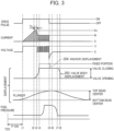
- Fig. 3 is a time chart illustrating operation of the high-pressure fuel pump 103 of the present embodiment.
- a rotation angle of the cam 201 attached to the crankshaft 110 is detected, and for example, after the crankshaft 110 rotates from a top dead center (TDC) by a predetermined angle (P-ON timing), a voltage V starts being applied to both ends of the solenoid 205 (timing t1).
- L and R are inductance and resistance of the solenoid 205 and wiring, respectively.
- Fmag magnetic attraction force
- timing t3 A period Th in which the current I is applied at the maximum value is present between the timing t2 and timing t3.
- the decrease in fuel pressure in the pressure chamber 211 causes the anchor 204 to move from the valve closing position to valve opening position with the inlet valve 203 (timing t7 to t8).
- Such operation allows the high-pressure fuel pump 103 to feed the fuel from the low-pressure pipe 111 to high-pressure pipe 104.
- noise is generated when the anchor 204 collides with the fixed portion 206 to complete valve closing (timing t4 of Fig. 3 ) and when the anchor 204 and inlet valve 203 collide with the stopper 208 to complete valve opening (timing t8 of Fig. 3 ).
- This noise may cause a driver to feel uncomfortable especially at idle.
- Automobile manufacturers and suppliers of the high-pressure fuel pump 103 compete for the noise reduction.
- the present embodiment focuses on reduction of the noise at completion of valve closing of the anchor 204 and inlet valve 203.
- the current for driving the high-pressure fuel pump 103 is roughly distinguished into two. These are a peak current (slash portion of the current wave of Fig. 3 ) and a holding current (lateral line portion of the current wave of Fig. 3 ).
- the peak current energizes, for valve closing, the inlet valve 203 and anchor 204 that are pressed by the spring 209 to be stationary at the valve opening position.
- the holding current attracts the anchor 204 that has approached the fixed portion 206 until the anchor 204 collides with the fixed portion 206. Then, after the anchor 204 collides with the fixed portion 206, the contact state is maintained.
- the peak current application amount is decreased, the momentum of the valve closing of the inlet valve 203 and anchor 204 is made lower to achieve noise reduction.
- the peak current application amount is required to be minimized. Note that, as in Fig. 3 , the maximum current value of the peak current is Im, and the maximum current value of the holding current is Ik.
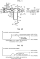
- Fig. 4 is a block diagram illustrating the high-pressure fuel pump 103 of First Embodiment.
- a role of the high-pressure fuel pump 103 compresses the fuel of the low-pressure pipe 111 and ejects the fuel to the high-pressure pipe 104 to keep the fuel pressure in the high-pressure pipe 104 at a target value. Therefore, the fuel pressure in the high-pressure pipe 104 is measured using a fuel-pressure sensor 401, and to make a fuel pressure measurement value follow the target fuel pressure, the current application start timing (P-ON timing) is controlled by an ejection amount control unit 403 according to the block diagram as illustrated in Fig. 4 . The ejection amount control is to control the current application start timing (P-ON timing).
- the P-ON timing is made early to increase the ejection amount ejected to the high-pressure pipe 104.
- the P-ON timing is made late to reduce the ejection amount ejected to the high-pressure pipe 104.
- a PID control is applied in general.
- a plunger phase measurement unit 402 that measures a phase angle of the plunger 202 may be provided to the cam 201 near the plunger 202.
- Fig. 5A is an explanatory diagram illustrating operation of the valve body when the valve closing is successful in the present embodiment.
- Fig. 5B is an explanatory diagram illustrating an operation of the valve body when the valve closing is failed in the present embodiment.
- the noise reduction is further achieved as the peak current is further reduced, but excessive reduction of the peak current causes failure of the valve closing of the inlet valve 203 and anchor 204.
- a sufficient peak current allows the valve body of the inlet valve 203 to move.
- Fig. 5B when an only insufficient peak current is provided, the valve body of the inlet valve 203 is overcome by the spring force of the first spring 209 and fails to perform valve closing.
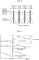
- Fig. 6 is a concept diagram illustrating how to identify success or failure of the valve closing of the inlet valve 203 from the rise of the fuel pressure in sync with the rise of the plunger 202 of the present embodiment.
- this difference is identified.
- the current application amount is increased when the valve closing of the inlet valve 203 is failed, and the current application amount is decreased when the valve closing of the inlet valve 203 is successful. These operations are repeated.
- the current is controllable around the minimum current application amount achieving the valve closing of the inlet valve 203.
- This control of the current is noise reduction control. According to the noise reduction control, the noise on the valve closing of the high-pressure fuel pump 103 can be reduced.
- Fig. 7 is an explanatory diagram illustrating change of the fuel pressure when the present invention is not applied.
- Fig. 7 illustrates a relationship of the fuel pressure of the high-pressure pipe 104, the current application start timing P-ON, and the current application amount when the ejection amount control and noise reduction control are applied to the high-pressure fuel pump 103.
- the fuel pressure pulsates until around 150 ms at a cycle of 37.5 ms. This pulsation is generated because success in the valve closing of the inlet valve 203 causes the increase in pressure due to the rise of the plunger 202 to be transferred to the high-pressure pipe 104, and on the other hand, the pressure of the high-pressure pipe 104 decreases due to the fuel injection of the direct injection injector 105, these processes being repeated.
- the current application amount at this time gradually decreases while the valve closing of the inlet valve 203 is successful until 150 ms.
- the current application amount increases because the failure in the valve closing of the inlet valve 203 is detected at a cycle from 150 ms to 187.5 ms.
- the current application start timing is made early suddenly at around 200 ms. This is because, in the ejection amount control, the decrease in fuel pressure due to the failure in valve closing of the inlet valve 203 caused by excessive decrease in current application amount is determined to be due to late current application start timing. In addition, this is because, in the ejection amount control, the current application start timing is made early to compensate for the decrease in fuel pressure.
- Such phenomenon is called interference of noise reduction control and ejection amount control.
- the present embodiment provides a solution for the interference.
- the ECU 112 performs a cooperative control of the ejection amount control and noise reduction control (hereinafter described as an interference reduction control) to reduce the above interference of the ejection amount control and noise reduction control.
- the ejection amount control is performed at a cycle of 10 ms.
- the noise reduction control is performed at a cycle of 2 ms. This cycle is not necessarily limiting.
- the noise reduction control needs to detect pulsation of the fuel pressure in sync with the rise of the plunger 202 and thus needs to be at a cycle short enough to detect this pulsation.
- the cycle of the ejection amount control does not need to be as short as the cycle of the noise reduction control.
- the cycle of the ejection amount control may be aligned to the cycle of the noise reduction control for, e.g., simplification of software. The increase in calculation load needs to be considered.
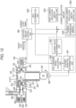
- Fig. 8 is a block diagram illustrating the high-pressure fuel pump 103 of the present embodiment and each control unit of an ECU 112.
- the high-pressure fuel pump 103 is controlled by the ECU 112.
- the fuel-pressure sensor 401 is disposed to the high-pressure pipe 104.
- the plunger phase measurement unit 402 that measures a phase angle of the plunger 202 is provided to the plunger cam 201 near the plunger 202.
- the plunger phase measurement unit 402 is a rotation angle sensor that detects a rotation angle of the cam 201 to measure a phase of the plunger 202 from the rotation angle of the cam 201.
- the ECU 112 includes a plunger operation determination unit 801 that determines that the plunger 202 is rising based on a phase angle of the plunger 202.
- the ECU 112 includes a fuel-pressure rising evaluation unit 802 that evaluates the rise of the fuel pressure in the period in which the plunger operation determination unit 801 determines that the plunger 202 is rising.
- the ECU 112 includes a closing valve determination unit 803 that determines success or failure of the valve closing of the inlet valve 203 based on the evaluation result of the fuel-pressure rising evaluation unit 802.
- the ECU 112 includes an ejection amount control unit 804 that controls an ejection amount of fuel by controlling a current application start timing for the solenoid 205 based on the fuel pressure measured by the fuel-pressure sensor 401 and a target fuel pressure.
- the ejection amount control unit 804 determines a control gain of the current application start timing based on the determination result of the closing valve determination unit 803. That is, the ejection amount control unit 804 reduces the control gain of the current application start timing when the determination result of the closing valve determination unit 803 indicates failure of the valve closing.
- the ejection amount control unit 804 performs control to make the current application start timing earlier based on the predetermined relationship of a fuel pressure and current application start timing when the determination result of the closing valve determination unit 803 indicates failure of the valve closing. That is, the ejection amount control unit 804 performs control to make the control gain of the current application start timing earlier based on the determination result of the closing valve determination unit 803 at the latest control cycle in control of the current application amount for the solenoid by a current application amount control unit 805.
- the ECU 112 includes the current application amount control unit 805 that controls the current application amount for the solenoid 205 based on the determination result of the closing valve determination unit 803.
- Fig. 9 is a flowchart illustrating noise reduction control of the present embodiment performed every 2 ms.
- the ECU 112 calculates a phase angle of the plunger 202 of the high-pressure fuel pump 103 by the plunger phase measurement unit 402 based on a crank angle calculated from a crank angle sensor and a phase difference between a cam angle and crank angle from a variable valve mechanism control device (step 901).
- the plunger operation determination unit 801 of the ECU 112 determines whether the plunger phase angle reaches a start angle in a preset fuel pressure change calculation range (step 902). When the plunger phase angle reaches the start angle in the preset fuel pressure change calculation range at step 902, the processing proceeds to step 903. When the plunger phase angle does not reach the start angle in the preset fuel pressure change calculation range at step 902, the processing proceeds to step 904.
- the fuel-pressure rising evaluation unit 802 of the ECU 112 sets the fuel pressure measurement value as a fuel pressure at the start of the rising (step 903). After the process at step 903, the processing waits for the next interrupt of 2 ms.
- the plunger operation determination unit 801 of the ECU 112 determines whether the phase angle of the plunger 202 reaches an end angle in the preset fuel pressure change calculation range (step 904).
- the processing proceeds to step 905.
- the ECU 112 waits for the next interrupt of 2 ms after the process at step 904.
- the fuel-pressure rising evaluation unit 802 of the ECU 112 sets the fuel pressure measurement value as a fuel pressure at the end of the rising (step 905).
- the fuel-pressure rising evaluation unit 802 of the ECU 112 subtracts the fuel pressure at the start of rising set at step 903 from the fuel pressure at the end of rising set at step 905 to calculate a fuel pressure rise value (step 906).
- the closing valve determination unit 803 of the ECU 112 determines whether the fuel pressure rise value calculated at step 906 is larger than a threshold value (step 907). When the fuel pressure rise value is larger than a threshold value at step 907, the processing proceeds to step 908, and the valve closing is determined to be successful (step 908). The processing proceeds to step 910 after the process of step 908. When the fuel pressure rise value is not larger than the threshold value at step 907, the processing proceeds to step 909, and the valve closing is determined to be failed (step909). The processing proceeds to step 911 after the process at step 909.
- the current application amount control unit 805 of the ECU 112 reduces the current application amount when the processing proceeds to step 908 and the valve closing is successful (step 910).
- the current application amount is increased (step 911). Then, the ECU 112 waits for the next interrupt of 2 ms after the processes at step 910 and step 911.
- the current application amount is controlled near the minimum valve with which the valve closing is successful to realize noise reduction.
- Fig. 10 is a flowchart illustrating an ejection amount control of the present embodiment performed every 10 ms.
- the ejection amount control is performed at a cycle of 10 ms.
- the ejection amount control unit 804 of the ECU 112 determines whether the latest valve closing determination in the noise reduction control performed at a cycle of 2 ms is determined to be successful (step 1001).
- the ejection amount control unit 804 of the ECU 112 selects a gain of a fuel pressure feedback by distinguishing whether the valve closing is determined to be successful at step 1001.
- step 1001 When the valve closing is determined to be successful at step 1001, the processing of the ejection amount control unit 804 of the ECU 112 proceeds to step 1002.
- the ejection amount control unit 804 of the ECU 112 selects a feedback gain for the success (step 1002).
- the processing of the ejection amount control unit 804 of the ECU 112 proceeds to step 1003.
- the ejection amount control unit 804 of the ECU 112 selects a smaller feedback gain for failure than the feedback gain for the success to prevent the current application start timing from being made excessively early in spite of no problem in ejection amount control (step 1003).
- the ejection amount control unit 804 of the ECU 112 reads a fuel-pressure sensor signal that is a fuel pressure from the fuel-pressure sensor 401 (step 1004).
- the processing of the ECU 112 proceeds to step 1005 after the process at step 1004.
- the ejection amount control unit 804 of the ECU 112 uses the above determined gain to control the current application start timing, e.g., with a PID control (step 1005). After the process at step 1005, the ECU 112 waits for an interrupt of 10 ms.
- Fig. 11 is an explanatory diagram illustrating a state of reduction of pressure pulsation of the present embodiment.
- a feedback gain of the ejection amount control in case of failure in valve closing can be reduced.
- an excessively early current application start timing can be suppressed.
- Fig. 11 illustrates one example for a fuel pressure, current application amount, and current application start timing when this control is applied. Compared to Fig. 7 before the present embodiment is applied, an excessively early current application start timing is suppressed after 187. 5 ms at which failure of valve closing is detected. Thereby, it is obvious that no-pulsation of the fuel pressure can be reduced.
- the present embodiment describes noise reduction performed only when an operational state of the internal combustion engine 100 is at idle.
- the noise other than that of the high-pressure fuel pump 103 is small. For this reason, the operating sound of the high-pressure fuel pump 103 is conspicuous.
- a current application amount for the solenoid 205 is controlled.
- Fig. 12 is a block diagram illustrating the high-pressure fuel pump 103 of the present embodiment.
- the ECU 112 includes a first current application amount control unit (the current application amount control unit in First Embodiment) 1201 that controls a current application amount for the solenoid 205 only when the operational state of the internal combustion engine 100 is determined to be at idle.
- the first current application amount control unit 1201 performs a first current control that controls the current application amount for the solenoid 205 based on the determination result of the closing valve determination unit 803.
- the ECU 112 includes a second current application amount control unit 1202 that performs a second current control to control the current application amount for the solenoid 205 based on the predetermined relationship between a target fuel pressure and current application start timing.
- the ECU 112 includes an idle determination unit 1203 that determines whether the operational state of the internal combustion engine 100 is at idle. When the operational state of the internal combustion engine 100 is determined to be at idle, the ECU 112 makes the first current application amount control unit 1201 perform the noise reduction control (the first current control). When the operational state of the internal combustion engine 100 is determined not to be at idle, the ECU 112 makes the second current application amount control unit 1202 perform the second current control.
- the idle determination unit 1203 that determines whether the operational state of the internal combustion engine 100 is at idle is added to the configuration illustrated in Fig. 8 .
- a current parameter memory 1204 that stores a current parameter of the second current application amount control unit 1202 to control the current application amount by use of a predetermined current parameter without performing noise reduction control when the operational state of the internal combustion engine 100 is other than at idle is added.
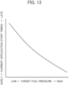
- Fig. 13 is an explanatory diagram illustrating a map of a correlation between a target fuel pressure and current application timing of Second Embodiment.
- a map of a current parameter illustrated in Fig. 13 is a map illustrating a correlation between a target fuel pressure and current application timing previously acquired in an experiment etc., and is stored on the current parameter memory 1204.
- the second current application amount control unit 1202 of the ECU 112 determines, as the second current control, the current application start timing in response to the target fuel pressure by use of the map of the current parameter.
- the current application start timing is controlled to be early, and when the measurement value of the fuel pressure is higher than target fuel pressure, the current application start timing is controlled to be late.
- Fig. 14 is a flowchart illustrating an interference reduction control between an ejection amount control and noise reduction control (the first current application amount control) in response to the operational state of the internal combustion engine of the present embodiment.
- the idle determination unit 1203 of the ECU 112 determines whether the internal combustion engine 100 is at idle based on, e.g., an idol signal, the number of rotations or load of the internal combustion engine from the ECU 112 (step 1401). When the determination result indicates the idle state at step 1401, the processing proceeds to step 1402. When the determination result indicates other than the idle state at step 1401, the processing proceeds to step 1403.
- the noise reduction control in the first current application amount control unit 1201 illustrated in Fig. 9 is performed at a cycle of 2 ms (step 1402), and the ejection amount control illustrated in Fig. 10 is performed at a cycle of 10 ms (step 1403). Since the flow of this processing is the same as First Embodiment, the noise reduction control is performed based on the valve closing detection result, and a gain of the ejection amount control is suppressed on the valve closing.
- the ejection amount control is performed every 10 ms (step 1403).
- the second current control is performed by the second current application amount control unit 1202 (step 1404).
- the noise reduction is not performed.
- the second current control is performed based on the current parameter memory 1204. A feedback control based on the fuel pressure on the rise of the plunger 202 is not performed.
- the noise reduction control can be performed only when the operational state of the internal combustion engine 100 is at idle.
- the valve closing is failed at a certain frequency.
- the valve closing failure causes fuel pressure pulsation.
- the influence of fuel pressure pulsation becomes small when the operational state of the internal combustion engine 100 is at idle. Therefore, by performing the noise reduction control only when the operational state of the internal combustion engine 100 is at idle, the influence of fuel pressure pulsation can be suppressed at an acceptable level.
- the ejection amount control unit 804 reduces a feedback gain when the valve closing is determined to be failed. This reduces an unnecessary angle advance of the current application start timing due to the decrease in fuel pressure based on the valve closing failure caused by the excessive decrease in current for noise reduction.
- the current application start timing is held as a map of a target fuel pressure. Then, the feedback of the fuel pressure is not performed.
- the current application start timing is held as the map of the target fuel pressure, and the feedback of the fuel pressure is not performed. For this reason, when the valve closing failure is recognized, the control is performed using a simple map. The excessive angle advance of the current application timing is suppressed, and the fuel pressure pulsation can be reduced.
- the valve closing is detected based on the rise of the fuel pressure in sync with the plunger 202.
- the current application amount is gradually reduced.
- the valve closing is failed, the current application amount is increased.
- the current application amount is adapted for each body.
- the valve closing is intentionally failed at a certain frequency.
- the current application amount is held around the minimum current application amount for each body.
- the fuel pressure pulsation due to the failed valve closing with such a method as First Embodiment may be unacceptable.
- the minimum current application amount of the pump is learned, e.g., at key ON.
- the pump is controlled using the minimum current value based on this learning.
- a feedback gain is preferably changed not to make the current application start timing P-ON earlier than necessary.
- Fig. 15 is a block diagram illustrating the high-pressure fuel pump 103 of the present embodiment.
- the ECU 112 includes the first current application amount control unit 1201 (the current application amount control unit in First Embodiment) to perform the noise reduction control (the first current control) that controls the current application amount for the solenoid 205 based on the determination result of the closing valve determination unit 803.
- the ECU 112 includes a third current application amount control unit 1501 to perform a third current control that controls the current application amount for the solenoid 205 based on a predetermined relationship between current application start timing and a current application amount.
- the third current control does not perform a feedback control based on the fuel pressure at the rise of the plunger 202, and determines a current application amount in response to a current application start timing by using a map of a current parameter of a current parameter memory 1503.
- the ECU 112 includes a learning period determination unit 1502 that determines whether a learning period is in process to learn a valve closing minimum current application amount of the high-pressure fuel pump 103.
- the ECU 112 performs the noise reduction control using the first current application amount control unit 1201 during the learning period. Outside the learning period, the ECU 112 acquires the determination result of the closing valve determination unit 803 every predetermined period, and performs the third current control by the third current application amount control unit 1501 based on the acquired determination result.
- the learning period determination unit 1502 that determines whether the operational state of the internal combustion engine 100 is in the learning period is added to the configuration of Fig. 8 .
- the current parameter memory 1503 that stores a current parameter of the third current application amount control unit 1501 to control the current application amount by use of a predetermined current parameter without performing the noise reduction control outside the learning period is added.
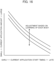
- Fig. 16 is an explanatory diagram illustrating a map that adjusts a correlation between the current application start timing and current application amount stored on the current parameter memory 1503 of the present embodiment by use of learning of each body.
- the map of the current parameter illustrated in Fig. 16 is a map that adjusts the correlation between the current application start timing and current application amount previously acquired in an experiment etc. by learning of each body, and that is stored on the current parameter memory 1503.
- the map of the current parameter illustrates multiple feature lines indicating that, when the current application start timing is high, the current application amount tends to be low, and when the current application start timing is low, the current application amount timing tends to be high.
- the multiple feature lines indicating this tendency are used by being moved mainly in the large or small direction of the current application amount to follow the learning of each body.
- the third current application amount control unit 1501 of the ECU 112 determines a current application amount in response to the current application start timing by using the map of the current parameter as the third current control.
- Fig. 17 is a flowchart illustrating an interference reduction control between the ejection amount control and first current application control (noise reduction control) in response to the learning state of the internal combustion engine 100 of the present embodiment.
- the learning determination unit 1502 of the ECU 112 determines whether the internal combustion engine 100 is in the learning period based on an idol signal from the ECU 112 or the number of rotations or load of the internal combustion engine 100. (step 1701). When the determination result indicates the state in the learning period at step 1401, the processing proceeds to step 1702. When the determination result indicates the state outside the learning period at step 1701, the processing proceeds to step 1703.
- the noise reduction control (the first current application amount control) in the first current application amount control unit 1201 illustrated in Fig. 9 is performed at a cycle of 2 ms (step 1702), and the ejection amount control illustrated in Fig. 10 is performed at a cycle of 10 ms (step 1703). Since the flow of this processing is the same as First Embodiment, the noise reduction control is performed based on the valve closing detection result, and a gain of the ejection amount control is suppressed on the valve closing.
- the ejection amount control is performed every 10 ms (step 1703).
- the valve closing determination is performed by the closing valve determination unit 803 of the ECU 112 (step 1704).
- the noise reduction control is not performed
- the third current application amount control 1501 performs the third current control based on the current parameter memory 1503, and the feedback control based on the fuel pressure at the rise of the plunger 202 is not performed.
- the gain of the feedback control of PON timing is changed based on whether the valve closing is successful or failed in the latest valve closing determination. Thereby, not to perform excessive control, the decrease in fuel pressure due to the failed valve closing is prevented from being misunderstood as the decrease in fuel pressure due to the control of PON timing.
- the excessive PON control can be prevented from occurring by the fuel pressure fluctuation due to the failed valve closing.
- 100 internal combustion engine
- 101 fuel tank
- 102 feed pump
- 103 high-pressure fuel pump
- 104 high-pressure pipe
- 105 direct injection injector
- 106 cylinder
- 107 piston
- 108 ignition plug
- 109 link mechanism
- 110 crankshaft
- 111 low-pressure pipe
- 112 ECU (control device for high-pressure fuel pump)
- 200 electromagnetic actuator
- 201 cam
- 202 plunger
- 203 inlet valve
- 204 anchor
- 205 solenoid
- 206 fixed portion
- 207 seat portion
- 209 first spring
- 210 ejection valve
- 211 pressure chamber
- 212 flow path
- 215 second spring
- 221 communication port
- 222 outflow port
- 223 casing
- 226 spring part
- 401 fuel-pressure sensor
- 402 plunger phase measurement unit
- 403 ejection amount control unit
- 801 plunger operation determination unit
- 802 fuel-pressure rising
Landscapes
- Engineering & Computer Science (AREA)
- Chemical & Material Sciences (AREA)
- Combustion & Propulsion (AREA)
- Mechanical Engineering (AREA)
- General Engineering & Computer Science (AREA)
- Fuel-Injection Apparatus (AREA)
- Electrical Control Of Air Or Fuel Supplied To Internal-Combustion Engine (AREA)
Abstract
Description
- The present invention relates to a control device for a high-pressure fuel pump.
- Internal combustion engines of automobiles are required to have high efficiency, low exhaust, and high power. It has been a long time since spreading of direct injection internal combustion engines as means for balanced solution for those. Manufacturers and suppliers for automobiles have made efforts constantly to improve the product values. One of subjects for the efforts is noise reduction of a high-pressure fuel pump.
- A current for driving a high-pressure fuel pump may be reduced to reduce noise of the pump. However, the high-pressure fuel pump cannot eject fuel when the reduction is excessive. Each high-pressure fuel pump has a different optimum current application amount for noise reduction.
- The conventional noise reduction for high-pressure fuel pumps is controlled as in
Patent Literature 1 to check the minimum current application amount for each high-pressure fuel pump to the extent that fuel ejection is not failed. The technology ofPatent Literature 1 achieves noise reduction by reducing a current (the second current). On the other hand, when the current is reduced excessively, the valve closing is insufficient. When an actual fuel pressure in a pressure accumulator decreases from a target fuel pressure by a predetermined value or more, the current is increased to resolve the insufficient valving. - Patent Literature 1:
Japanese Unexamined Patent Application Publication No. 2017-53247 - By the way, regardless of noise reduction control, a high-pressure fuel pump controls an ejection amount to make a fuel pressure follow a target value. The high-pressure fuel pump controls the ejection amount by controlling a start time of the current applied to a solenoid. Therefore, in the high-pressure fuel pump corresponding to noise reduction control, two controls, an ejection amount control using a current start timing and a noise reduction control using a current value, are performed in parallel.
- Problems herein include executions of the two controls using the comparison between a measurement value of a fuel pressure and a target fuel pressure and the interference between the two controls.
- In
Patent Literature 1, when the measurement value of the fuel pressure becomes lower than the target fuel pressure, the valve closing is determined to be insufficient, and the second current is made larger. On the other hand, in the ejection amount control, when the measurement value of the fuel pressure becomes lower than the target fuel pressure, the current application start timing is made early to increase the ejection amount. Without distinguishing whether the lower measurement value of the fuel pressure than the target fuel pressure is due to the current value or to the current application start timing, the two values are controlled. - Additionally, when the valve closing is failed, the fuel pressure is made lower than the target value. Thus, even the current application start timing at which a sufficient ejection amount is achievable is made early. This earlier current application timing causes an unnecessary fuel pressure pulsation.
- The present invention is to provide the control device for the high-pressure fuel pump to avoid pulsation of a fuel pressure due to an interference between two controls, an ejection amount control using a current start timing and a noise reduction control using a current value.
- To pressurize fuel in a low-pressure pipe and eject the fuel to a high-pressure pipe, the control device for the high-pressure fuel pump according to one embodiment of the present invention is disposed between both pipes. The control device controls the high-pressure pump. The high-pressure pump includes at least: an inlet valve disposed between the low-pressure pipe and a pressure chamber; a solenoid that controls opening and closing of the inlet valve; and a plunger that compresses fuel in the pressure chamber. A fuel-pressure sensor is disposed to the high-pressure pipe. A plunger phase measurement unit that measures a phase angle of the plunger is provided near the plunger. The control device includes; a plunger operation determination unit that determines that the plunger is rising based on a phase angle of the plunger; a fuel-pressure rising evaluation unit that evaluates rising of the fuel pressure during a period during which the plunger is determined to be rising by the plunger operation determination unit; a closing valve determination unit that determines success or failure of valve closing of the inlet valve based on an evaluation result of the fuel-pressure rising evaluation unit; and an ejection amount control unit that controls an ejection amount of fuel by controlling a current application start timing for the solenoid based on a fuel pressure measured by the fuel-pressure sensor and a target fuel pressure. The ejection amount control unit determines a control gain of the current application start timing based on a determination result of the closing valve determination unit.
- According to the present invention, the control device for the high-pressure fuel pump that avoids pulsation of a fuel pressure due to an interference between two controls of an ejection amount control using a current start timing and a noise reduction using a current value can be provided.
-
-
Fig. 1 is a schematic configuration diagram illustrating an internal combustion engine of First Embodiment. -
Fig. 2 is a schematic configuration diagram illustrating a high-pressure fuel pump of First Embodiment. -
Fig. 3 is a time chart illustrating operation of the high-pressure fuel pump of First Embodiment. -
Fig. 4 is a block diagram illustrating the high-pressure fuel pump of First Embodiment. -
Fig. 5A is an explanatory diagram illustrating operation of the valve body when the valve closing is successful in First Embodiment. -
Fig. 5B is an explanatory diagram illustrating an operation of the valve body when the valve closing is failed in First Embodiment. -
Fig. 6 is a concept diagram illustrating how to identify success or failure of the valve closing from the rise of the fuel pressure in sync with the rise of the plunger of the First Embodiment. -
Fig. 7 is an explanatory diagram illustrating change of a fuel pressure when the present invention is not applied. -
Fig. 8 is a block diagram illustrating the high-pressure fuel pump of First Embodiment and each control unit of an ECU. -
Fig. 9 is a flowchart illustrating a noise reduction control (current application amount control) of First Embodiment, the control being performed every 2 ms. -
Fig. 10 is a flowchart illustrating an ejection amount control of First Embodiment, the control being performed every 10 ms. -
Fig. 11 is an explanatory diagram illustrating a state of reduction of pressure pulsation of First Embodiment. -
Fig. 12 is a block diagram illustrating the high-pressure fuel pump of Second Embodiment. -
Fig. 13 is an explanatory diagram illustrating a map of a correlation between a target fuel pressure and current application timing of Second Embodiment. -
Fig. 14 is a flowchart illustrating an interference reduction control between an ejection amount control and a noise reduction control (first current application control) in response to the operational state of an internal combustion engine of Second Embodiment. -
Fig. 15 is a block diagram illustrating the high-pressure fuel pump of Fourth Embodiment. -
Fig. 16 is an explanatory diagram illustrating a map to adjust a correlation between a current application timing and a current application amount stored on a current parameter memory of Fourth Embodiment by using learning of each body. -
Fig. 17 is a flowchart illustrating an interference reduction control between an ejection amount control and a noise reduction control (first current application control) in response to the learning state of the internal combustion engine of Fourth Embodiment. Description of Embodiments - Hereinafter, in reference to the drawings, embodiments of the present invention are explained. Note that the present invention is not interpreted as being limited to the below embodiments. A technical concept of the present invention may be achieved by a combination of well-known other components. Note that the same elements in respective figures have the same reference symbols, and are not explained repeatedly. In each figure, the U direction indicates an up direction, the D direction indicates a down direction, the R direction indicates a right direction, and the L direction indicates a left direction.
- In the present embodiment, a valve body is opened when a current does not flow through a solenoid. Then, when a current flows through the solenoid, the valve body is closed. This valve closing prevents fuel compressed by the rising of a plunger from returning toward a low-pressure pipe, and the fuel is ejected toward a high-pressure pipe. A normal open type pump that performs such operation is described. However, the present embodiment is applicable also to a normal close type pump when valve closing is replaced with valve opening.
-
Fig. 1 is a schematic configuration diagram illustrating aninternal combustion engine 100 of the present embodiment. The outline of a direct injection internal combustion engine is illustrated inFig. 1 as theinternal combustion engine 100. In theinternal combustion engine 100, fuel stored in afuel tank 101 is pressurized to about 0.4 MPa with afeed pump 102, and further, is pressurized to tens of MPa with a high-pressure fuel pump 103 via a low-pressure pipe 111. The pressurized fuel is injected to a cylinder 106 of theinternal combustion engine 100 from a direct injection injector 105 via a high-pressure pipe 104. - The injected fuel is mixed with the air inhaled into the cylinder 106 by operation of a
piston 107. This mixture is ignited by a spark generated by anignition plug 108, and explodes. The mixture in the cylinder 106 expands by heat generated by the explosion, and presses thepiston 107 downward. The force that presses thepiston 107 downward rotates acrankshaft 110 via alink mechanism 109. The rotation of thecrankshaft 110 is transferred to wheels via a transmission to become a force to move a vehicle. - Such an
internal combustion engine 100 is controlled by an ECU (engine control unit) 112 that is a control device. When performing an operation control of theinternal combustion engine 100 using an electrical auxiliary device, theECU 112 is a microcontroller that controls those synthetically. TheECU 112 forms, e.g., a function part by cooperation with a program and an arithmetic unit. TheECU 112 is a control device that controls the high-pressure fuel pump 103. - Low fuel consumption, high output, and exhaust air purification are mainly required of the
internal combustion engine 100. Reduction of noise and vibration is required as further added values. In the high-pressure fuel pump 103, noise occurs due to the collision of the valve body andanchor 204 and astopper 208 in opening and closing of aninlet valve 203. Each automobile manufacturer and supplier make many efforts for the noise reduction. -
Fig. 2 is a schematic configuration diagram illustrating the high-pressure fuel pump 103 of the present embodiment.Fig. 2 illustrates a structure of the high-pressure fuel pump 103. The high-pressure fuel pump 103 includes aplunger 202 raised and lowered by rotation of acam 201 attached to thecrankshaft 110 of theinternal combustion engine 100. Theplunger 202 compresses fuel in apressure chamber 211. - The high-
pressure fuel pump 103 includes theinlet valve 203 that performs opening and closing operation in sync with the up and down motion of theplunger 202. To pressurize fuel in the low-pressure pipe 111 and eject the fuel to the high-pressure pipe 104, theinlet valve 203 is disposed between the low-pressure pipe 111 and thepressure chamber 211 between both pipes. - The high-
pressure fuel pump 103 includes asolenoid 205 that controls opening and closing operation of theinlet valve 203. The high-pressure fuel pump 103 includes theanchor 204 that is drawn by an electromagnetic force generated by thesolenoid 205 and that controls operation of theinlet valve 203. - The high-
pressure fuel pump 103 is surrounded by acasing 223, and forms thepressure chamber 211 therein. Fuel flows from the side of the low-pressure pipe 111 into thepressure chamber 211 through aninflow port 225 and acommunication port 221. The fuel that has flown into thepressure chamber 211 is ejected toward the high-pressure pipe 104 through anoutflow port 222. Theoutflow port 222 is opened and closed by anejection valve 210. Theejection valve 210 is normally energized to close theoutflow port 222 by aspring part 226. When the pressure of thepressure chamber 211 exceeds the spring force of thespring part 226, theoutflow port 222 opens and the fuel is injected. - In the high-
pressure fuel pump 103, on/off of energization of thesolenoid 205 is controlled to control axial movement (in the lateral direction ofFig. 2 ) of theanchor 204. In the off state of energization of thesolenoid 205, theanchor 204 keeps theinlet valve 203 at the valve opening position by being normally biased in the valve opening direction by afirst spring 209. Such a high-pressure fuel pump 103 is called a normal open type high-pressure fuel pump. The present embodiment explains a normal open type. However, the high-pressure fuel pump 103 is applicable also to a normal close type high-pressure fuel pump when valve opening and valve closing are replaced with each other. - When the energization of the
solenoid 205 is turned on, an electromagnetic attraction force occurs between a fixed portion (magnetic core) 206 and theanchor 204. Theanchor 204 provided on the base end side of theinlet valve 203 against the spring force of thefirst spring 209 is attracted in the valve opening direction (in the left direction L ofFig. 2 ). In the state where theanchor 204 is attracted to the fixedportion 206, theinlet valve 203 becomes a check valve opened and closed based on a difference pressure between the upstream side and downstream side and on a biasing force of asecond spring 215. Therefore, when the pressure downstream of theinlet valve 203 is raised, theinlet valve 203 moves in the valve closing direction. When moving in the valve closing direction by a set lift amount, theinlet valve 203 seats on aseat portion 207. Theinlet valve 203 enters the valve closed state. The fuel in thepressure chamber 211 cannot flow back toward the low-pressure pipe 111. -
Fig. 3 is a time chart illustrating operation of the high-pressure fuel pump 103 of the present embodiment. To make theinlet valve 203 open and close in sync with upward and downward movements of theplunger 202, a rotation angle of thecam 201 attached to thecrankshaft 110 is detected, and for example, after thecrankshaft 110 rotates from a top dead center (TDC) by a predetermined angle (P-ON timing), a voltage V starts being applied to both ends of the solenoid 205 (timing t1). This voltage V makes a current I flowing in thesolenoid 205
solenoid 205 and wiring, respectively. With increase in the current I, a magnetic attraction force Fmag with which the fixed portion (magnetic core) 206 attracts theanchor 204 also increases. - When the magnetic attraction force Fmag becomes greater than a force Fsp of the
first spring 209, theanchor 204 pressed by a spring force Fsp starts moving to the fixed portion 206 (timing t2). When theanchor 204 moves, theinlet valve 203 is pressed by the fuel pressurized by the rise of theplunger 202 and moves to the fixedportion 206 to follow theanchor 204. - Then, the current I decreases (timing t3). A period Th in which the current I is applied at the maximum value is present between the timing t2 and timing t3.
- Then, a projection of the
inlet valve 203 collides with and seats on theseat portion 207. This collision closes a flow path of the fuel (dotted line ofFig. 2 ), the fuel pressurized by the rise of theplunger 202 cannot flow back toward the low-pressure pipe 111, and the pressure in thepressure chamber 211 rises (timing t4). - When the pressure of the
pressure chamber 211 becomes larger than a spring force Fsp_out that presses theejection valve 210, theejection valve 210 is opened, and the fuel pressurized by the rise of theplunger 202 is ejected to the high-pressure pipe 104. After that, when the drive pulse is tuned off at timing t5, a reverse voltage is applied to thesolenoid 205, intercepting a holding current supplied to thesolenoid 205. - When the cam angle passes the top dead center and the
plunger 202 starts lowering (timing t6), the fuel pressure in thepressure chamber 211 falls. Then, when the fuel pressure becomes smaller than the spring force Fsp_out, theejection valve 210 is closed to terminate the ejection of the fuel. - Additionally, the decrease in fuel pressure in the
pressure chamber 211 causes theanchor 204 to move from the valve closing position to valve opening position with the inlet valve 203 (timing t7 to t8). - Such operation allows the high-
pressure fuel pump 103 to feed the fuel from the low-pressure pipe 111 to high-pressure pipe 104. In this processing, noise is generated when theanchor 204 collides with the fixedportion 206 to complete valve closing (timing t4 ofFig. 3 ) and when theanchor 204 andinlet valve 203 collide with thestopper 208 to complete valve opening (timing t8 ofFig. 3 ). This noise may cause a driver to feel uncomfortable especially at idle. Automobile manufacturers and suppliers of the high-pressure fuel pump 103 compete for the noise reduction. The present embodiment focuses on reduction of the noise at completion of valve closing of theanchor 204 andinlet valve 203. - The current for driving the high-
pressure fuel pump 103 is roughly distinguished into two. These are a peak current (slash portion of the current wave ofFig. 3 ) and a holding current (lateral line portion of the current wave ofFig. 3 ). The peak current energizes, for valve closing, theinlet valve 203 andanchor 204 that are pressed by thespring 209 to be stationary at the valve opening position. On the other hand, the holding current attracts theanchor 204 that has approached the fixedportion 206 until theanchor 204 collides with the fixedportion 206. Then, after theanchor 204 collides with the fixedportion 206, the contact state is maintained. When the peak current application amount is decreased, the momentum of the valve closing of theinlet valve 203 andanchor 204 is made lower to achieve noise reduction. However, excessive reduction of the peak current application amount causes failure of the valve closing of theinlet valve 203 andanchor 204. Therefore, to the extent that the valve closing of theinlet valve 203 andanchor 204 is made, the peak current application amount is required to be minimized. Note that, as inFig. 3 , the maximum current value of the peak current is Im, and the maximum current value of the holding current is Ik. -
Fig. 4 is a block diagram illustrating the high-pressure fuel pump 103 of First Embodiment. A role of the high-pressure fuel pump 103 compresses the fuel of the low-pressure pipe 111 and ejects the fuel to the high-pressure pipe 104 to keep the fuel pressure in the high-pressure pipe 104 at a target value. Therefore, the fuel pressure in the high-pressure pipe 104 is measured using a fuel-pressure sensor 401, and to make a fuel pressure measurement value follow the target fuel pressure, the current application start timing (P-ON timing) is controlled by an ejectionamount control unit 403 according to the block diagram as illustrated inFig. 4 . The ejection amount control is to control the current application start timing (P-ON timing). In the ejection amount control, when the fuel pressure measurement value is lower than the target fuel pressure, the P-ON timing is made early to increase the ejection amount ejected to the high-pressure pipe 104. In the ejection amount control, when the fuel pressure measurement value is higher than the target fuel pressure, the P-ON timing is made late to reduce the ejection amount ejected to the high-pressure pipe 104. In the ejection amount control, a PID control is applied in general. - Note that a plunger
phase measurement unit 402 that measures a phase angle of theplunger 202 may be provided to thecam 201 near theplunger 202. -
Fig. 5A is an explanatory diagram illustrating operation of the valve body when the valve closing is successful in the present embodiment.Fig. 5B is an explanatory diagram illustrating an operation of the valve body when the valve closing is failed in the present embodiment. As described in the above <<Peak Current and Holding Current>>, when the peak current application amount is reduced, the speed on the valve closing of theinlet valve 203 is reduced to achieve noise reduction. - The noise reduction is further achieved as the peak current is further reduced, but excessive reduction of the peak current causes failure of the valve closing of the
inlet valve 203 andanchor 204. As illustrated inFig. 5A , a sufficient peak current allows the valve body of theinlet valve 203 to move. However, as illustrated inFig. 5B , when an only insufficient peak current is provided, the valve body of theinlet valve 203 is overcome by the spring force of thefirst spring 209 and fails to perform valve closing. -
Fig. 6 is a concept diagram illustrating how to identify success or failure of the valve closing of theinlet valve 203 from the rise of the fuel pressure in sync with the rise of theplunger 202 of the present embodiment. When the valve closing of theinlet valve 203 is successful, the valve body of theinlet valve 203 closes the flow path from thepressure chamber 211 to the low-pressure pipe 111. Then, the increase in pressure due to the rise of theplunger 202 is transferred to the high-pressure pipe 104. Thereby, in sync with the rise of theplunger 202, the pressure of the high-pressure pipe 104 rises as in the portions of positively sloped lines ofFig. 6 . On the other hand, when the valve closing of theinlet valve 203 is failed, the fuel of thepressure chamber 211 escapes to the low-pressure pipe 111 even when theplunger 202 rises. The pressure of the high-pressure pipe 104 does not rise as in the portions of negatively sloped lines ofFig. 6 . - Based on a measurement value of the fuel-pressure sensor disposed to the high-
pressure pipe 104 or a common rail, this difference is identified. The current application amount is increased when the valve closing of theinlet valve 203 is failed, and the current application amount is decreased when the valve closing of theinlet valve 203 is successful. These operations are repeated. - In this way, based on the fuel pressure fluctuation in sync with the rising and lowering of the
plunger 202, success or failure of the valve closing of theinlet valve 203 is determined to increase or decrease the current application amount. Thus, the current is controllable around the minimum current application amount achieving the valve closing of theinlet valve 203. This control of the current is noise reduction control. According to the noise reduction control, the noise on the valve closing of the high-pressure fuel pump 103 can be reduced. -
Fig. 7 is an explanatory diagram illustrating change of the fuel pressure when the present invention is not applied.Fig. 7 illustrates a relationship of the fuel pressure of the high-pressure pipe 104, the current application start timing P-ON, and the current application amount when the ejection amount control and noise reduction control are applied to the high-pressure fuel pump 103. - In
Fig. 7 , the fuel pressure pulsates until around 150 ms at a cycle of 37.5 ms. This pulsation is generated because success in the valve closing of theinlet valve 203 causes the increase in pressure due to the rise of theplunger 202 to be transferred to the high-pressure pipe 104, and on the other hand, the pressure of the high-pressure pipe 104 decreases due to the fuel injection of the direct injection injector 105, these processes being repeated. - However, at 187.5 ms at which 37.5 ms has elapsed from 150 ms, no increase in fuel pressure is seen. This is because the valve closing of the
inlet valve 203 is failed and the increase in fuel pressure due to the rise of theplunger 202 escapes toward the low-pressure pipe 111 and is not transferred to the high-pressure pipe 104. By seeing such change, success or failure of the valve closing of theinlet valve 203 is determined. - The current application amount at this time gradually decreases while the valve closing of the
inlet valve 203 is successful until 150 ms. However, the current application amount increases because the failure in the valve closing of theinlet valve 203 is detected at a cycle from 150 ms to 187.5 ms. - On the other hand, it is obvious that the current application start timing is made early suddenly at around 200 ms. This is because, in the ejection amount control, the decrease in fuel pressure due to the failure in valve closing of the
inlet valve 203 caused by excessive decrease in current application amount is determined to be due to late current application start timing. In addition, this is because, in the ejection amount control, the current application start timing is made early to compensate for the decrease in fuel pressure. - Such phenomenon is called interference of noise reduction control and ejection amount control. The present embodiment provides a solution for the interference.
- The
ECU 112 performs a cooperative control of the ejection amount control and noise reduction control (hereinafter described as an interference reduction control) to reduce the above interference of the ejection amount control and noise reduction control. Herein, the ejection amount control is performed at a cycle of 10 ms. Herein, the noise reduction control is performed at a cycle of 2 ms. This cycle is not necessarily limiting. The noise reduction control needs to detect pulsation of the fuel pressure in sync with the rise of theplunger 202 and thus needs to be at a cycle short enough to detect this pulsation. Additionally, the cycle of the ejection amount control does not need to be as short as the cycle of the noise reduction control. The cycle of the ejection amount control may be aligned to the cycle of the noise reduction control for, e.g., simplification of software. The increase in calculation load needs to be considered. -
Fig. 8 is a block diagram illustrating the high-pressure fuel pump 103 of the present embodiment and each control unit of anECU 112. The high-pressure fuel pump 103 is controlled by theECU 112. - The fuel-
pressure sensor 401 is disposed to the high-pressure pipe 104. The plungerphase measurement unit 402 that measures a phase angle of theplunger 202 is provided to theplunger cam 201 near theplunger 202. The plungerphase measurement unit 402 is a rotation angle sensor that detects a rotation angle of thecam 201 to measure a phase of theplunger 202 from the rotation angle of thecam 201. - The
ECU 112 includes a plungeroperation determination unit 801 that determines that theplunger 202 is rising based on a phase angle of theplunger 202. TheECU 112 includes a fuel-pressure risingevaluation unit 802 that evaluates the rise of the fuel pressure in the period in which the plungeroperation determination unit 801 determines that theplunger 202 is rising. TheECU 112 includes a closingvalve determination unit 803 that determines success or failure of the valve closing of theinlet valve 203 based on the evaluation result of the fuel-pressure risingevaluation unit 802. - The
ECU 112 includes an ejectionamount control unit 804 that controls an ejection amount of fuel by controlling a current application start timing for thesolenoid 205 based on the fuel pressure measured by the fuel-pressure sensor 401 and a target fuel pressure. The ejectionamount control unit 804 determines a control gain of the current application start timing based on the determination result of the closingvalve determination unit 803. That is, the ejectionamount control unit 804 reduces the control gain of the current application start timing when the determination result of the closingvalve determination unit 803 indicates failure of the valve closing. - In detail, the ejection
amount control unit 804 performs control to make the current application start timing earlier based on the predetermined relationship of a fuel pressure and current application start timing when the determination result of the closingvalve determination unit 803 indicates failure of the valve closing. That is, the ejectionamount control unit 804 performs control to make the control gain of the current application start timing earlier based on the determination result of the closingvalve determination unit 803 at the latest control cycle in control of the current application amount for the solenoid by a current applicationamount control unit 805. - The
ECU 112 includes the current applicationamount control unit 805 that controls the current application amount for thesolenoid 205 based on the determination result of the closingvalve determination unit 803. -
Fig. 9 is a flowchart illustrating noise reduction control of the present embodiment performed every 2 ms. - First, when an interrupt at a cycle of 2 ms occurs, the
ECU 112 calculates a phase angle of theplunger 202 of the high-pressure fuel pump 103 by the plungerphase measurement unit 402 based on a crank angle calculated from a crank angle sensor and a phase difference between a cam angle and crank angle from a variable valve mechanism control device (step 901). - The plunger
operation determination unit 801 of theECU 112 determines whether the plunger phase angle reaches a start angle in a preset fuel pressure change calculation range (step 902). When the plunger phase angle reaches the start angle in the preset fuel pressure change calculation range atstep 902, the processing proceeds to step 903. When the plunger phase angle does not reach the start angle in the preset fuel pressure change calculation range atstep 902, the processing proceeds to step 904. - The fuel-pressure rising
evaluation unit 802 of theECU 112 sets the fuel pressure measurement value as a fuel pressure at the start of the rising (step 903). After the process at step 903, the processing waits for the next interrupt of 2 ms. - On the other hand, the plunger
operation determination unit 801 of theECU 112 determines whether the phase angle of theplunger 202 reaches an end angle in the preset fuel pressure change calculation range (step 904). When the plunger phase angle reaches the end angle in the preset fuel pressure change calculation range at step 904, the processing proceeds to step 905. When the plunger phase angle does not reach the end angle in the preset fuel pressure change calculation range at step 904, theECU 112 waits for the next interrupt of 2 ms after the process at step 904. - The fuel-pressure rising
evaluation unit 802 of theECU 112 sets the fuel pressure measurement value as a fuel pressure at the end of the rising (step 905). - After the process at step 905, the fuel-pressure rising
evaluation unit 802 of theECU 112 subtracts the fuel pressure at the start of rising set at step 903 from the fuel pressure at the end of rising set at step 905 to calculate a fuel pressure rise value (step 906). - The closing
valve determination unit 803 of theECU 112 determines whether the fuel pressure rise value calculated at step 906 is larger than a threshold value (step 907). When the fuel pressure rise value is larger than a threshold value at step 907, the processing proceeds to step 908, and the valve closing is determined to be successful (step 908). The processing proceeds to step 910 after the process of step 908. When the fuel pressure rise value is not larger than the threshold value at step 907, the processing proceeds to step 909, and the valve closing is determined to be failed (step909). The processing proceeds to step 911 after the process at step 909. - The current application
amount control unit 805 of theECU 112 reduces the current application amount when the processing proceeds to step 908 and the valve closing is successful (step 910). When the processing proceeds to step 909 and the valve closing is failed, the current application amount is increased (step 911). Then, theECU 112 waits for the next interrupt of 2 ms after the processes at step 910 and step 911. - Thus, by performing the noise reduction control at a cycle of 2 ms, the current application amount is controlled near the minimum valve with which the valve closing is successful to realize noise reduction.
-
Fig. 10 is a flowchart illustrating an ejection amount control of the present embodiment performed every 10 ms. The ejection amount control is performed at a cycle of 10 ms. - When an interrupt at a cycle of 10 ms occurs, the ejection
amount control unit 804 of theECU 112 determines whether the latest valve closing determination in the noise reduction control performed at a cycle of 2 ms is determined to be successful (step 1001). The ejectionamount control unit 804 of theECU 112 selects a gain of a fuel pressure feedback by distinguishing whether the valve closing is determined to be successful atstep 1001. - When the valve closing is determined to be successful at
step 1001, the processing of the ejectionamount control unit 804 of theECU 112 proceeds to step 1002. The ejectionamount control unit 804 of theECU 112 selects a feedback gain for the success (step 1002). - When the valve closing is determined to be failed at
step 1001, the processing of the ejectionamount control unit 804 of theECU 112 proceeds to step 1003. The ejectionamount control unit 804 of theECU 112 selects a smaller feedback gain for failure than the feedback gain for the success to prevent the current application start timing from being made excessively early in spite of no problem in ejection amount control (step 1003). - Next, the ejection
amount control unit 804 of theECU 112 reads a fuel-pressure sensor signal that is a fuel pressure from the fuel-pressure sensor 401 (step 1004). The processing of theECU 112 proceeds to step 1005 after the process at step 1004. - Then, in response to a difference between the fuel pressure read at step 1004 and a target fuel pressure, the ejection
amount control unit 804 of theECU 112 uses the above determined gain to control the current application start timing, e.g., with a PID control (step 1005). After the process at step 1005, theECU 112 waits for an interrupt of 10 ms. -
Fig. 11 is an explanatory diagram illustrating a state of reduction of pressure pulsation of the present embodiment. According to the present embodiment, a feedback gain of the ejection amount control in case of failure in valve closing can be reduced. Thereby, an excessively early current application start timing can be suppressed.Fig. 11 illustrates one example for a fuel pressure, current application amount, and current application start timing when this control is applied. Compared toFig. 7 before the present embodiment is applied, an excessively early current application start timing is suppressed after 187. 5 ms at which failure of valve closing is detected. Thereby, it is obvious that no-pulsation of the fuel pressure can be reduced. - The present embodiment describes noise reduction performed only when an operational state of the
internal combustion engine 100 is at idle. When the operational state of theinternal combustion engine 100 is at idle, the noise other than that of the high-pressure fuel pump 103 is small. For this reason, the operating sound of the high-pressure fuel pump 103 is conspicuous. Thus, there is need for noise reduction performed only when the operational state is at idle. Then, only when the operational state of theinternal combustion engine 100 is determined to be at idle, a current application amount for thesolenoid 205 is controlled. -
Fig. 12 is a block diagram illustrating the high-pressure fuel pump 103 of the present embodiment. TheECU 112 includes a first current application amount control unit (the current application amount control unit in First Embodiment) 1201 that controls a current application amount for thesolenoid 205 only when the operational state of theinternal combustion engine 100 is determined to be at idle. In detail, the first current applicationamount control unit 1201 performs a first current control that controls the current application amount for thesolenoid 205 based on the determination result of the closingvalve determination unit 803. TheECU 112 includes a second current application amount control unit 1202 that performs a second current control to control the current application amount for thesolenoid 205 based on the predetermined relationship between a target fuel pressure and current application start timing. TheECU 112 includes anidle determination unit 1203 that determines whether the operational state of theinternal combustion engine 100 is at idle. When the operational state of theinternal combustion engine 100 is determined to be at idle, theECU 112 makes the first current applicationamount control unit 1201 perform the noise reduction control (the first current control). When the operational state of theinternal combustion engine 100 is determined not to be at idle, theECU 112 makes the second current application amount control unit 1202 perform the second current control. - In the configuration of the present embodiment, the
idle determination unit 1203 that determines whether the operational state of theinternal combustion engine 100 is at idle is added to the configuration illustrated inFig. 8 . Additionally, acurrent parameter memory 1204 that stores a current parameter of the second current application amount control unit 1202 to control the current application amount by use of a predetermined current parameter without performing noise reduction control when the operational state of theinternal combustion engine 100 is other than at idle is added. -
Fig. 13 is an explanatory diagram illustrating a map of a correlation between a target fuel pressure and current application timing of Second Embodiment. A map of a current parameter illustrated inFig. 13 is a map illustrating a correlation between a target fuel pressure and current application timing previously acquired in an experiment etc., and is stored on thecurrent parameter memory 1204. - On the map of the current parameter, when the target fuel pressure is high, the current application start timing tends to be early, and when the target fuel pressure is low, the current application start timing tends to be late. The second current application amount control unit 1202 of the
ECU 112 determines, as the second current control, the current application start timing in response to the target fuel pressure by use of the map of the current parameter. On the map of the current parameter, when the measurement value of the fuel pressure is lower than the target fuel pressure, the current application start timing is controlled to be early, and when the measurement value of the fuel pressure is higher than target fuel pressure, the current application start timing is controlled to be late. -
Fig. 14 is a flowchart illustrating an interference reduction control between an ejection amount control and noise reduction control (the first current application amount control) in response to the operational state of the internal combustion engine of the present embodiment. - When a time interrupt (10 ms in general) occurs, the
idle determination unit 1203 of theECU 112 determines whether theinternal combustion engine 100 is at idle based on, e.g., an idol signal, the number of rotations or load of the internal combustion engine from the ECU 112 (step 1401). When the determination result indicates the idle state at step 1401, the processing proceeds to step 1402. When the determination result indicates other than the idle state at step 1401, the processing proceeds to step 1403. - When the determination result indicates the idle state at step 1401, the noise reduction control in the first current application
amount control unit 1201 illustrated inFig. 9 is performed at a cycle of 2 ms (step 1402), and the ejection amount control illustrated inFig. 10 is performed at a cycle of 10 ms (step 1403). Since the flow of this processing is the same as First Embodiment, the noise reduction control is performed based on the valve closing detection result, and a gain of the ejection amount control is suppressed on the valve closing. - When the determination result indicates other than the idle state at step 1401, the ejection amount control is performed every 10 ms (step 1403). On the other hand, the second current control is performed by the second current application amount control unit 1202 (step 1404). Herein, the noise reduction is not performed. In the second current application amount control, the second current control is performed based on the
current parameter memory 1204. A feedback control based on the fuel pressure on the rise of theplunger 202 is not performed. - According to the present embodiment, the noise reduction control can be performed only when the operational state of the
internal combustion engine 100 is at idle. When the noise reduction control is performed, the valve closing is failed at a certain frequency. However, the valve closing failure causes fuel pressure pulsation. The influence of fuel pressure pulsation becomes small when the operational state of theinternal combustion engine 100 is at idle. Therefore, by performing the noise reduction control only when the operational state of theinternal combustion engine 100 is at idle, the influence of fuel pressure pulsation can be suppressed at an acceptable level. - In First Embodiment, the ejection
amount control unit 804 reduces a feedback gain when the valve closing is determined to be failed. This reduces an unnecessary angle advance of the current application start timing due to the decrease in fuel pressure based on the valve closing failure caused by the excessive decrease in current for noise reduction. - Instead of this, in the present embodiment, when the valve closing failure is recognized, the current application start timing is held as a map of a target fuel pressure. Then, the feedback of the fuel pressure is not performed.
- According to the present embodiment, when the valve closing failure is recognized, the current application start timing is held as the map of the target fuel pressure, and the feedback of the fuel pressure is not performed. For this reason, when the valve closing failure is recognized, the control is performed using a simple map. The excessive angle advance of the current application timing is suppressed, and the fuel pressure pulsation can be reduced.
- In First Embodiment, the valve closing is detected based on the rise of the fuel pressure in sync with the
plunger 202. During the successful valve closing, the current application amount is gradually reduced. When the valve closing is failed, the current application amount is increased. Thus, the current application amount is adapted for each body. In the method of First Embodiment, the valve closing is intentionally failed at a certain frequency. Thus, the current application amount is held around the minimum current application amount for each body. However, the fuel pressure pulsation due to the failed valve closing with such a method as First Embodiment may be unacceptable. - In such a case, the minimum current application amount of the pump is learned, e.g., at key ON. The pump is controlled using the minimum current value based on this learning. When the valve closing is failed due to disturbance such as fuel pressure fluctuation, a feedback gain is preferably changed not to make the current application start timing P-ON earlier than necessary.
-
Fig. 15 is a block diagram illustrating the high-pressure fuel pump 103 of the present embodiment. TheECU 112 includes the first current application amount control unit 1201 (the current application amount control unit in First Embodiment) to perform the noise reduction control (the first current control) that controls the current application amount for thesolenoid 205 based on the determination result of the closingvalve determination unit 803. TheECU 112 includes a third current applicationamount control unit 1501 to perform a third current control that controls the current application amount for thesolenoid 205 based on a predetermined relationship between current application start timing and a current application amount. The third current control does not perform a feedback control based on the fuel pressure at the rise of theplunger 202, and determines a current application amount in response to a current application start timing by using a map of a current parameter of acurrent parameter memory 1503. TheECU 112 includes a learningperiod determination unit 1502 that determines whether a learning period is in process to learn a valve closing minimum current application amount of the high-pressure fuel pump 103. TheECU 112 performs the noise reduction control using the first current applicationamount control unit 1201 during the learning period. Outside the learning period, theECU 112 acquires the determination result of the closingvalve determination unit 803 every predetermined period, and performs the third current control by the third current applicationamount control unit 1501 based on the acquired determination result. - In the configuration of the present embodiment, the learning
period determination unit 1502 that determines whether the operational state of theinternal combustion engine 100 is in the learning period is added to the configuration ofFig. 8 . Thecurrent parameter memory 1503 that stores a current parameter of the third current applicationamount control unit 1501 to control the current application amount by use of a predetermined current parameter without performing the noise reduction control outside the learning period is added. -
Fig. 16 is an explanatory diagram illustrating a map that adjusts a correlation between the current application start timing and current application amount stored on thecurrent parameter memory 1503 of the present embodiment by use of learning of each body. The map of the current parameter illustrated inFig. 16 is a map that adjusts the correlation between the current application start timing and current application amount previously acquired in an experiment etc. by learning of each body, and that is stored on thecurrent parameter memory 1503. - The map of the current parameter illustrates multiple feature lines indicating that, when the current application start timing is high, the current application amount tends to be low, and when the current application start timing is low, the current application amount timing tends to be high. The multiple feature lines indicating this tendency are used by being moved mainly in the large or small direction of the current application amount to follow the learning of each body. The third current application
amount control unit 1501 of theECU 112 determines a current application amount in response to the current application start timing by using the map of the current parameter as the third current control. -
Fig. 17 is a flowchart illustrating an interference reduction control between the ejection amount control and first current application control (noise reduction control) in response to the learning state of theinternal combustion engine 100 of the present embodiment. - When a time interrupt (10 ms in general) occurs, the learning
determination unit 1502 of theECU 112 determines whether theinternal combustion engine 100 is in the learning period based on an idol signal from theECU 112 or the number of rotations or load of theinternal combustion engine 100. (step 1701). When the determination result indicates the state in the learning period at step 1401, the processing proceeds to step 1702. When the determination result indicates the state outside the learning period at step 1701, the processing proceeds to step 1703. - When the determination result indicates the state in the learning period at step 1701, the noise reduction control (the first current application amount control) in the first current application
amount control unit 1201 illustrated inFig. 9 is performed at a cycle of 2 ms (step 1702), and the ejection amount control illustrated inFig. 10 is performed at a cycle of 10 ms (step 1703). Since the flow of this processing is the same as First Embodiment, the noise reduction control is performed based on the valve closing detection result, and a gain of the ejection amount control is suppressed on the valve closing. - When the determination result indicates the state outside the learning period at step 1701, the ejection amount control is performed every 10 ms (step 1703). On the other hand, the valve closing determination is performed by the closing
valve determination unit 803 of the ECU 112 (step 1704). Herein, the noise reduction control is not performed, the third currentapplication amount control 1501 performs the third current control based on thecurrent parameter memory 1503, and the feedback control based on the fuel pressure at the rise of theplunger 202 is not performed. - Then, as illustrated in
Fig. 10 , in the ejection amount control, the gain of the feedback control of PON timing is changed based on whether the valve closing is successful or failed in the latest valve closing determination. Thereby, not to perform excessive control, the decrease in fuel pressure due to the failed valve closing is prevented from being misunderstood as the decrease in fuel pressure due to the control of PON timing. - According to the present embodiment, even when the valve closing is failed by rapid change in fuel pressure etc., the excessive PON control can be prevented from occurring by the fuel pressure fluctuation due to the failed valve closing.
- As above, the embodiments of the present invention have been explained. The above embodiments indicate only part of the application examples of the present invention. The technical scope of the present invention is not intended to be limited to the specific configurations of the above embodiments.
- 100: internal combustion engine, 101: fuel tank, 102: feed pump, 103: high-pressure fuel pump, 104: high-pressure pipe, 105: direct injection injector, 106: cylinder, 107: piston, 108: ignition plug, 109: link mechanism, 110: crankshaft, 111: low-pressure pipe, 112: ECU (control device for high-pressure fuel pump), 200: electromagnetic actuator, 201: cam, 202: plunger, 203: inlet valve, 204: anchor, 205: solenoid, 206: fixed portion, 207: seat portion, 208: stopper, 209: first spring, 210: ejection valve, 211: pressure chamber, 212: flow path, 215: second spring, 221: communication port, 222: outflow port, 223: casing, 225: inflow port, 226: spring part, 401: fuel-pressure sensor, 402: plunger phase measurement unit, 403: ejection amount control unit, 801: plunger operation determination unit, 802: fuel-pressure rising evaluation unit, 803: closing valve determination unit, 804: ejection amount control unit, 805: current application amount control unit, 1201: first current application amount control unit, 1202: second current application amount control unit, 1203: idle determination unit, 1204: current parameter memory, 1501: third current application amount control unit, 1502: learning period determination unit, 1503: current parameter memory
Claims (5)
- A control device for a high-pressure fuel pump that controls a high-pressure fuel pump, the high-pressure fuel pump being disposed between a low-pressure pipe and a high-pressure pipe to pressurize fuel in the low-pressure pipe and eject the fuel to the high-pressure pipe, the high-pressure fuel pump including at least: an inlet valve disposed between the low-pressure pipe and a pressure chamber; a solenoid that controls opening and closing of the inlet valve; and a plunger that compresses fuel in the pressure chamber,wherein a fuel-pressure sensor is disposed to the high-pressure pipe,a plunger phase measurement unit that measures a phase angle of the plunger is provided near the plunger,the control device for the high-pressure fuel pump comprising:a plunger operation determination unit that determines that the plunger is rising based on a phase angle of the plunger;a fuel-pressure rising evaluation unit that evaluates rising of a fuel pressure in a period in which the plunger operation determination unit determines that the plunger is rising;a closing valve determination unit that determines success or failure of valve closing of the inlet valve based on an evaluation result of the fuel-pressure rising evaluation unit; andan ejection amount control unit that controls an ejection amount of fuel by controlling a current application start timing for the solenoid based on a fuel pressure measured by the fuel-pressure sensor and a target fuel pressure,wherein the ejection amount control unit determines a control gain of a current application start timing based on a determination result of the closing valve determination unit.
- The control device for the high-pressure fuel pump according to claim 1 further comprising:
a current application amount control unit that controls a current application amount for the solenoid based on a determination result of the closing valve determination unit. - The control device for the high-pressure fuel pump according to claim 1 wherein,
the ejection amount control unit reduces a control gain of a current application start timing when a determination result of the closing valve determination unit indicates a failure of valve closing. - The control device for the high-pressure fuel pump according to claim 1 wherein,
the ejection amount control unit controls a current application start timing based on a predetermined relationship between a fuel pressure and the current application start timing when a determination result of the closing valve determination unit indicates a failure of valve closing. - The control device for the high-pressure fuel pump according to claim 2 wherein,
the current application amount control unit controls a current application amount for the solenoid only when an operational state of an internal combustion engine is determined to be at idle.
Applications Claiming Priority (2)
| Application Number | Priority Date | Filing Date | Title |
|---|---|---|---|
| JP2022066996A JP7814227B2 (en) | 2022-04-14 | 2022-04-14 | High-pressure fuel pump control device |
| PCT/JP2023/006423 WO2023199612A1 (en) | 2022-04-14 | 2023-02-22 | Control device for high-pressure fuel pump |
Publications (2)
| Publication Number | Publication Date |
|---|---|
| EP4509708A1 true EP4509708A1 (en) | 2025-02-19 |
| EP4509708A4 EP4509708A4 (en) | 2026-03-25 |
Family
ID=88329240
Family Applications (1)
| Application Number | Title | Priority Date | Filing Date |
|---|---|---|---|
| EP23788034.9A Pending EP4509708A4 (en) | 2022-04-14 | 2023-02-22 | CONTROL DEVICE FOR A HIGH-PRESSURE FUEL PUMP |
Country Status (4)
| Country | Link |
|---|---|
| EP (1) | EP4509708A4 (en) |
| JP (1) | JP7814227B2 (en) |
| CN (1) | CN118679312A (en) |
| WO (1) | WO2023199612A1 (en) |
Family Cites Families (7)
| Publication number | Priority date | Publication date | Assignee | Title |
|---|---|---|---|---|
| JP2007327409A (en) | 2006-06-07 | 2007-12-20 | Toyota Motor Corp | Fuel supply device for internal combustion engine |
| DE102009026690A1 (en) * | 2008-06-04 | 2009-12-10 | DENSO CORPORATION, Kariya-shi | The fuel feeding apparatus |
| JP6432471B2 (en) | 2015-09-08 | 2018-12-05 | 株式会社デンソー | High pressure fuel pump solenoid valve control device and high pressure fuel pump solenoid valve control method |
| DE102016215779A1 (en) * | 2016-08-23 | 2018-03-01 | Robert Bosch Gmbh | Method for operating a high-pressure fuel pump with an electrically controllable intake valve for an internal combustion engine |
| JP2021032178A (en) * | 2019-08-27 | 2021-03-01 | 日立オートモティブシステムズ株式会社 | Electromagnetic actuator controller, high pressure fuel pump and injector |
| JP7303764B2 (en) * | 2020-02-28 | 2023-07-05 | 日立Astemo株式会社 | High pressure fuel pump controller |
| JP7349024B2 (en) * | 2020-06-03 | 2023-09-21 | 日立Astemo株式会社 | Solenoid valve control device |
-
2022
- 2022-04-14 JP JP2022066996A patent/JP7814227B2/en active Active
-
2023
- 2023-02-22 CN CN202380021378.7A patent/CN118679312A/en active Pending
- 2023-02-22 EP EP23788034.9A patent/EP4509708A4/en active Pending
- 2023-02-22 WO PCT/JP2023/006423 patent/WO2023199612A1/en not_active Ceased
Also Published As
| Publication number | Publication date |
|---|---|
| EP4509708A4 (en) | 2026-03-25 |
| JP2023157225A (en) | 2023-10-26 |
| CN118679312A (en) | 2024-09-20 |
| WO2023199612A1 (en) | 2023-10-19 |
| JP7814227B2 (en) | 2026-02-16 |
Similar Documents
| Publication | Publication Date | Title |
|---|---|---|
| EP2317105B1 (en) | High-pressure fuel supply pump and fuel supply system | |
| US7905215B2 (en) | Fuel supply apparatus | |
| US9121360B2 (en) | Method for operating a fuel injection system of an internal combustion engine | |
| EP2282044B1 (en) | High-pressure fuel supply pump | |
| JP3707210B2 (en) | Fuel injection control device | |
| EP2239445A1 (en) | High pressure fuel pump control device for engine | |
| JP7349024B2 (en) | Solenoid valve control device | |
| EP3249213B1 (en) | High-pressure fuel supply device for internal combustion engine | |
| EP3358175A1 (en) | High-pressure fuel pump and control device | |
| EP1777402B1 (en) | High-pressure fuel supply system using variable displacement fuel pump | |
| US20170082099A1 (en) | Device for controlling high-pressure pump | |
| CN116263140A (en) | Reduced energy waveform for energizing solenoid actuators in fuel injector valves | |
| JP2002221069A (en) | Control device for internal combustion engine provided with fuel supply device | |
| JP2014145339A (en) | Control device of high pressure pump | |
| US11852093B2 (en) | Control device for high-pressure fuel pump | |
| JPH02191865A (en) | Fuel injection device | |
| JP7814227B2 (en) | High-pressure fuel pump control device | |
| KR20250165637A (en) | Gas injector control method | |
| US11519372B2 (en) | Control device for high-pressure pump and method for controlling the same | |
| US11236697B2 (en) | Fuel injection control device and fuel injection control method | |
| US10473077B2 (en) | Control device for high-pressure pump | |
| JP2021032178A (en) | Electromagnetic actuator controller, high pressure fuel pump and injector | |
| JP7845203B2 (en) | fuel supply device | |
| WO2025258199A1 (en) | Fuel injection control device and fuel injection control method | |
| JP2025033268A (en) | Accumulator-type fuel injection control device |
Legal Events
| Date | Code | Title | Description |
|---|---|---|---|
| STAA | Information on the status of an ep patent application or granted ep patent |
Free format text: STATUS: THE INTERNATIONAL PUBLICATION HAS BEEN MADE |
|
| PUAI | Public reference made under article 153(3) epc to a published international application that has entered the european phase |
Free format text: ORIGINAL CODE: 0009012 |
|
| STAA | Information on the status of an ep patent application or granted ep patent |
Free format text: STATUS: REQUEST FOR EXAMINATION WAS MADE |
|
| 17P | Request for examination filed |
Effective date: 20241114 |
|
| AK | Designated contracting states |
Kind code of ref document: A1 Designated state(s): AL AT BE BG CH CY CZ DE DK EE ES FI FR GB GR HR HU IE IS IT LI LT LU LV MC ME MK MT NL NO PL PT RO RS SE SI SK SM TR |
|
| DAV | Request for validation of the european patent (deleted) | ||
| DAX | Request for extension of the european patent (deleted) | ||
| RAP3 | Party data changed (applicant data changed or rights of an application transferred) |
Owner name: ASTEMO, LTD. |
|
| A4 | Supplementary search report drawn up and despatched |
Effective date: 20260223 |
|
| RIC1 | Information provided on ipc code assigned before grant |
Ipc: F02M 59/02 20060101AFI20260217BHEP Ipc: F02M 59/20 20060101ALI20260217BHEP Ipc: F02M 59/36 20060101ALI20260217BHEP Ipc: F02D 41/38 20060101ALI20260217BHEP Ipc: F02D 41/40 20060101ALI20260217BHEP |